Installation Instructions for Lambo Door Mechanism. 1. Lift the hood and remove left and right shield of front wheel.
|
|
|
- Jack Cox
- 5 years ago
- Views:
Transcription


1 Installation Instructions for Lambo Door Mechanism 1. Lift the hood and remove left and right shield of front wheel.
 and then remove the rubber hose of the wires.")
2 2. With the door open pull out the rubber hose connecting the door and the door frame, draw out and cut the wire (wrap the two ends of every cut wires with friction tape and record the given numbers. If the wires are long enough, it s not necessary to cut.) and then remove the rubber hose of the wires.

3 3. With door closed remove the factory top door hinge. 4. Test and draw the placement of the mechanism. Pay attention to the moving way of the swing arm and ensure the swing arm up to 90 not to touch the shield or fender. So the mechanism must be in a proper height, which can be tested by the shield.


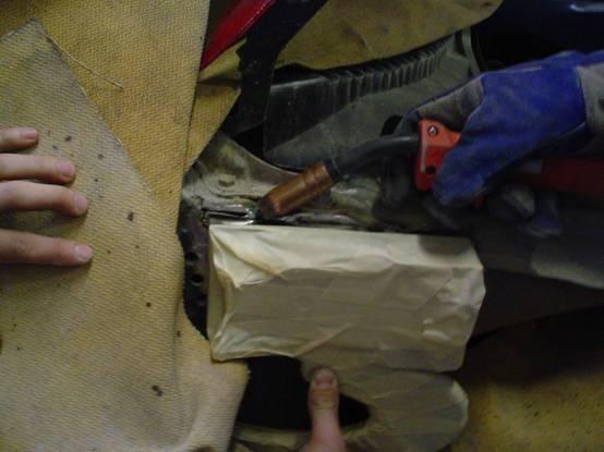
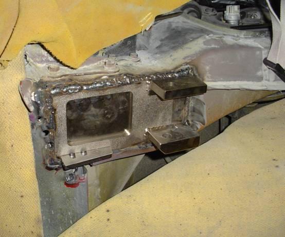
4 5. AGrind the installation placement of the chassis or hammer any extrusions that may hinder the base plates from sitting flat. You may also grind and cut the base plate and door plate as needed.

5 B. After grinding the installation placement, test the proper distance with the shield and check and observe any places that may prevent the base plate and the swing arm from moving. In this situation you must draw a line around the base plate when it is in the proper, and then cut or hammer along the perimeter till not to hinder. C. In cars with small spaces between the chassis surface and the fender there will not be sufficient room to install. It can be solved as follows: with the position of the base plate determined, draw a line around the base plate when it is in the proper position, and then cut along the perimeter to allow the base plate to slide below the surface.


6 6. Determine the holding position and space. Draw the position of the safety arch on the base plate and cut it. Cut a slot in the chassis to accommodate the arch, and if the base plate is below the chassis surface for your application make additional space for adjustment with a hex key.

7 7. Next you should cover the base plate, door, and the rest parts of the door mechanism in welding defletion paper with the exception of the surface of the surface that will get welded for the surface protection.

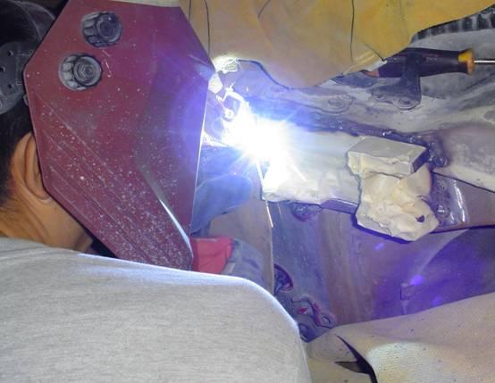
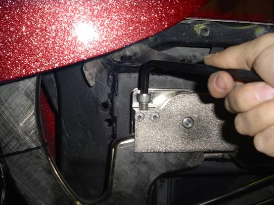
8 8. When the door mechanism clings to the chassis, door place, and moves smoothly and is proper in both horizontal and vertical direction after testing again, weld spots around the perimeter of the base plate and the door plate. When you feel the welds are sturdy enough, remove the down door hinge. You may observe and test whether the door is in the correct motion and position by swinging it out and up manually. Now you can make adjustments at the door outward motion screws, safety set screw and door height screws etc. on the door mechanism.
9
10
11

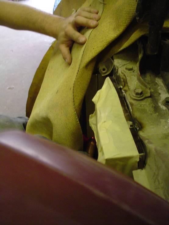
12 9. Determine and draw on the shield or fender the position space of the swing arm s motion and cut it. Test it again and cut the inner lip to provide clearance for the swing arm.
")
13 10. Once you are satisfied with the operation and placement like opening, closing, lifting and falling of the door and door mechanism, hammer the hinge center axis of the mechanism from top to bottom and then remove the door. Make a strong weld around the entire perimeter of the base plate and door plate. (Parts must be prevented from broiling of the high temperature while welding.)
14


15 11. Grind and scuff the welds surface and mask the undercoat paint and top coating to prevent rust.


16 12. Lube the moving surfaces of the door mechanism with heavy waterproof grease and then close the door, align the hinge holes and interpose the center axis to the holes form top to bottom and then hammer it well and smoothly.


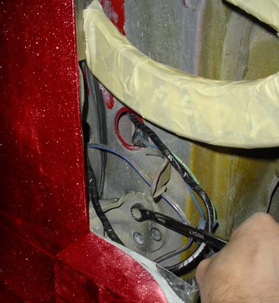
17 13. When the door is open up to the maximum angle, clear up the wires. Measure the wires and connect to the required length with other wires if it is not long enough. Remember to connect with the numbers while cutting and to mask the joints with the insulation tapes. With the wires plaited into cluster, fixed at the bottom of the swing arm with plastic and string.


18 14. Open the door and rotate it to the highest point, screw two ball joints into the swing arm and gas spring connecting plot respectively with gas spring screws and then determine and mark the spot where the ball joint will get mounted on the chassis.

19 15. Put the door down for now and disconnect the gas spring ball screw form the gas spring connecting plot and then hammer or grind the fixed position of the connecting plot and weld it well on the fixed place. Paint for dust prevention. 16. Open the door to the highest point and screw the gas spring ball points into the connecting plot and lock the ball points on the swing arm tightly at the same time. And test the doors motion. The swing arm should be parallel and not interferes with the gas spring or other parts when the door moves up and down.

20 17. With the door closed, test the door s horizontal motion until the door is aligned with the latch and closes perfectly. Adjust the safety arch until the door mechanism no longer interferes with the shield or fender when the door out all the way horizontally. Then set the horizontal motion screws to correspond with the angle that the safety arch rubs the inside of the lifting arm when up. The closer you make these two adjustments, the more sturdy the door will feel going up and resting in the vertical position. Set the vertical height limiter adjustment as high as you wish provided that the door does not hit the shield or other parts.

21

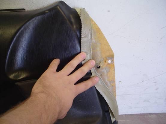
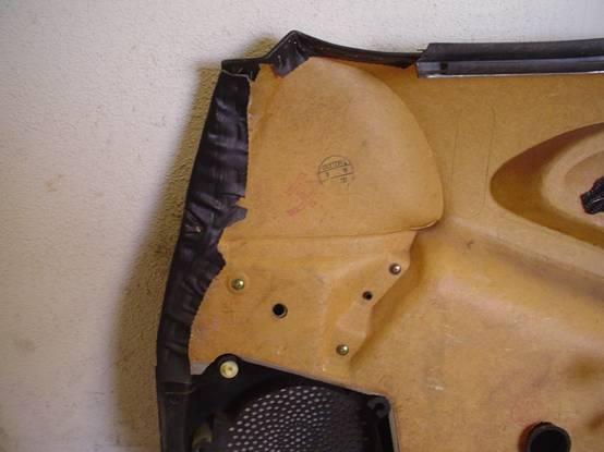
22 18. If the door panel and/or door metal hits the shield or comes too close to the shield on the way up it must be cut. If the door panel must be cut first mark a line that will allow clearance. Then peel back the upholstery, make the cut and wrap the upholstery over the new edge with spray adhesive.
23


24 19.Test it again until no any hinder and satisfied with everything; seal the screw adhesive to all the screw points. 20. Mount the shield, fender etc. and put down the hood. And you are done!
OTHER TOOLS MAY BE NEEDED DEPENDING ON YOUR VEHICLE.
 THIS KIT INCLUDES: 16 M8-1.25X40MM BOLTS WITH WASHERS 2 SHOCKS 720 PSI RIGHT AND LEFT HINGE ASSEMBLY 2 SHOULDER BOLTS 2 PINS TOOLS REQUIRED FOR INSTALLATION: AIR RACHET, GRINDER AND CUTTER. 10MM, 11MM,
TOOLS REQUIRED FOR INSTALLATION: AIR RACHET, GRINDER AND CUTTER.
 THIS KIT INCLUDES: 16 M8-1.25X30MM BOLTS WITH WASHERS 2 SHOCKS 565 PSI RIGHT AND LEFT HINGE ASSEMBLY 2 SHOULDER BOLTS 2 PINS TOOLS REQUIRED FOR INSTALLATION: AIR RACHET, GRINDER AND CUTTER. 7/23, 10MM,
THIS KIT INCLUDES: 8 M8-1.25X40MM BOLTS WITH WASHERS 8 M8-1.25X30MM BOLTS WITH WASHERS RIGHT AND LEFT HINGE
 Sal es@lambodoorscanada. com 2407A Kal adarave,ottawa,on K1V 8B9 THIS KIT INCLUDES: 8 M8-1.25X40MM BOLTS WITH WASHERS 8 M8-1.25X30MM BOLTS WITH WASHERS RIGHT AND LEFT HINGE 2 SHOCKS 565 PSI 2 SHOULDER
Page 1 of 12 GENERAL INSTRUCTIONS KHJKK Installation
 Page 1 of 12 KHJKK PICTURE ABOVE IS THE UNIVERSAL KIT; YOUR KIT MAY BE DIFFERENT. THIS KIT INCLUDES: 8 M8-1.25X30MM BOLTS WITH WASHERS 8 M8-1.25X40MM BOLTS WITH WASHERS 2 PINS RIGHT AND LEFT HINGE ASSEMBLY
WARNING!! DO NOT LIFT DOORS UP WHEN THE HOOD IS OPEN. THE DOORS WILL HIT THE HOOD!
 WARNING!! DO NOT LIFT DOORS UP WHEN THE HOOD IS OPEN. THE DOORS WILL HIT THE HOOD! THIS KIT INCLUDES: 4 M8-1.25X30MM BOLTS WITH WASHERS 12 M8-1.25X40MM BOLTS WITH WASHERS 2 SHOULDER BOLTS WITH RIGHT AND
CORVETTE CORVETTE REV: Made in USA U.S. PATENT #6,808,223; #6,845,547; #7,140,075; #7,059,655 and other patents pending.
 CORVETTE 2005-2006 CORVETTE 2005-2007 REV: 7-2-07 Made in USA U.S. PATENT #6,808,223; #6,845,547; #7,140,075; #7,059,655 and other patents pending. Page 1 of 12 CORVETTE C6 2005-2007 THIS KIT INCLUDES:
2 SHOULDER BOLTS RIGHT AND LEFT HINGE USE 4 EXISITING DOOR BOLTS TOOLS REQUIRED FOR INSTALLATION: AIR RACHET, GRINDER AND CUTTER.
 Page 1 of 12 NISSAN 350Z 2003-2004 THIS KIT INCLUDES: 8 BOLTS WITH WASHERS 2 SHOCKS 780 PSI 2 PINS 2 SHOULDER BOLTS RIGHT AND LEFT HINGE USE 4 EXISITING DOOR ASSEMBLY BOLTS TOOLS REQUIRED FOR INSTALLATION:
Slide the stock rubber tank mount caps onto the ends of the CS-1 tank mount:
 RYCA CS-1 BODY PARTS INSTALLATION GUIDE [The CS-1 installation guides should be used as supplements to the videos found on our Youtube Channel. There is no strict order to the build process, but it is
CORVETTE Page 1 of 12 CORVETTE C
 CORVETTE 2005-2006 Page 1 of 12 CORVETTE C5 1997-2004 THIS KIT INCLUDES: 8 M8-1.25X40MM BOLTS WITH WASHERS 8 M8-1.25X30MM BOLTS WITH WASHERS RIGHT AND LEFT HINGE ASSEMBLY WIRE LOOM 2 SHOCKS 565 PSI 2 SHOULDER
Ford F150 Front Bumper
 2009-2011 Ford F150 Front Bumper Warning! Read the instructions completely before beginning the installation. Before tightening bolts, drilling or cutting where required, check to make sure that there
*Patent Pending. *Trademarked. Series II. Glass Conversion Kit. (888) One-Products (888)
 One-Products (888)") *Patent Pending *Trademarked Series II Glass Conversion Kit www.onepieceproducts.com (888) One-Products (888) 663-7763 Installation Manual Full One Piece Door Glass Conversion Kit Series II 1967-1972 Chevy
*Patent Pending *Trademarked Series II Glass Conversion Kit www.onepieceproducts.com (888) One-Products (888) 663-7763 Installation Manual Full One Piece Door Glass Conversion Kit Series II 1967-1972 Chevy
B A T H R O O M G L A S S
 mistley B A T H R O O M G L A S S vaug16 Page 2 Thank you for purchasing this Trinity shower screen. Please study these instructions carefully before assembly and installation and check all supplied parts
TUBULAR FRONT END KIT INSTALLATION INSTRUCTIONS MUSTANG
 TUBULAR FRONT END KIT INSTALLATION INSTRUCTIONS 1979 2004 MUSTANG Pre-Installation Notes & Recommendations: Before disassembly, remove anything within the engine bay that can be removed; this will give
IMPORTANT: PLEASE RETAIN THIS INSTRUCTION MANUAL FOR FUTURE REFERENCE
 IMPORTANT: PLEASE RETAIN THIS INSTRUCTION MANUAL FOR FUTURE REFERENCE 005-07 Cadillac STS Classic 3D Z, Classic Dual Weave, Classic Mesh & Classic Black Mesh Grilles B 7 HR 3 STS Classic 3D Z Grille Part
Deauville Installation Guide
 vjul16 (for 17 or 24 mm Surface Wall Profiles) DO NOT ASSEMBLE WITHOUT FULLY READING THESE INSTRUCTIONS Page 2 Thank you for purchasing this Deauville shower enclosure. Please study these instructions
Paco Motorsports Strong Arms X
 Paco Motorsports Strong Arms 13-101X Thanks for purchasing our Strong Arms. These braces reinforce the frame horns that support the engine and transfer all of the cornering and road impact loads into the
Please read these Installation Instructions in their entirety prior to installing or operating this equipment.
 2014-2017 Ram 2500 (All beds) Please read these in their entirety prior to installing or operating this equipment. This hitch is rated to 30,000 lbs. Gross Towing Weight and 7,500 lbs. Tongue Weight Bolt
GMC Cut-Out Fender Flares Set of 4
 GMC Cut-Out Fender Flares Set of 4 STEP 1 PRIOR TO INSTALLATION A) Bushwacker only approves installing the fl ares according to these written instructions with the hardware provided. WARNING: Failure to
ZODIAC 601 XL. Outside Flashing 6C3-3. Mark the no rivet zone for Extrusion Handle 6C3-8
 Outside Flashing 6C3-3 Mark the no rivet zone for Extrusion Handle 6C3-8 Cleco the inside and outside flashing to the canopy side frame before the canopy bubble is fitted. Ref. Front edge 50mm back from
GMC Cut-Out Fender Flares Set of 4
 GMC Cut-Out Fender Flares Set of 4 STEP 1 PRIOR TO INSTALLATION A) Bushwacker only approves installing the fl ares according to these written instructions with the hardware provided. WARNING: Failure to
INSTALLATION MANUAL FORTRESS SERIES
 Guardian Security Structures TEL 1-406-212-2334 EMAIL rg@gssdoors.com WEB www.gssdoors.com FORTRESS SERIES GENERAL INSTALLATION GUIDELINES 1. The door frame is installed using 16 bolt screws 7,5 mm in
Chevrolet Cut-Out Fender Flares Set of 4
 Chevrolet Cut-Out Fender Flares Set of 4 STEP 1 PRIOR TO INSTALLATION A) Bushwacker only approves installing the fl ares according to these written instructions with the hardware provided. WARNING: Failure
Portofino Case2 Installation Guide
 Portofino Case2 Installation Guide vjun16 (for 17 or 24 mm Surface Wall Profile) DO NOT ASSEMBLE WITHOUT FULLY READING THESE INSTRUCTIONS Page 2 Thank you for purchasing this Portofino Case 2 shower enclosure.
Jeep Cherokee Door XJ Set Part # Revision J
 Jeep Cherokee 84-96 4 Door XJ Set Part # 10911 Revision J 6-5-06 Step 1: Prior to Installation: A) Fit: Verify the fit of the flares to vehicle. (Some filing, sanding, or cutting may be necessary to ensure
Chevrolet Cut-Out Fender Flares Set of 4
 Chevrolet Cut-Out Fender Flares Set of 4 STEP 1 PRIOR TO INSTALLATION A) Bushwacker only approves installing the fl ares according to these written instructions with the hardware provided. WARNING: Failure
Lumber Smith. Assembly Manual. If you are having problems assembling the saw and need assistance, please contact us at:
 Lumber Smith Assembly Manual If you are having problems assembling the saw and need assistance, please contact us at: 804-577-7398 info@lumbersmith.com 1 Step 1 Safety Carefully read the Owners Manual.
Installation for Full Size Polaris Ranger Crew Doors
 Installation for Full Size Polaris Ranger Crew Doors Order of Installation: Heater Doors Wiper on to Windshield Windshield Top & Back Panel Note: Most of the steps in these instructions need to be repeated
Chevrolet Cut-Out Fender Flares Front Pair
 Chevrolet Cut-Out Fender Flares Front Pair STEP 1 PRIOR TO INSTALLATION A) Bushwacker only approves installing the fl ares according to these written instructions with the hardware provided. WARNING: Failure
Deauville Installation Guide
 vjul16 (for Recessed Wall Profiles) DO NOT ASSEMBLE WITHOUT FULLY READING THESE INSTRUCTIONS Page 2 Thank you for purchasing this Deauville shower enclosure. Please study these instructions carefully before
TOOL LIST FOR TAILGATE HIDDEN LATCH & LINK ASSY FOR FORD FLARESIDE TRUCKS
 TOOL LIST FOR TAILGATE HIDDEN LATCH & LINK ASSY FOR 53-87 FORD FLARESIDE TRUCKS Vise Grip Clamps C-clamps Sharpie Marker Ball Peen Hammer Center Punch 3/8 or 1/2 Drill 5/32, 7/32, 9/32, and 3/8 Drill Bits
Rubber Grommet, 36 pcs. 3/4 Screw, 10 pcs. Nut, 10 pcs
 Jeep Cherokee ZJ Set Part #10916-07 Rev-2 03-11-10 THESE INSTRUCTIONS INVOLVE CUTTING THE FENDERS OF THE VEHICLE. IT IS IMPORTANT TO READ ALL INSTRUCTIONS PRIOR TO THE CUTTING AND INSTALLATION OF THESE
DF Rivet Bit 4.3mm TYX Coated Drill Bit. DF-5125P Self-Centering Rivet Drill. DF Rivet Bit 6.8mm TYX Coated Drill Bit
 DF-51243 Rivet Bit 4.3mm TYX Coated Drill Bit Specialized Self-Centering Rivet Drill Bit DF-5125P Self-Centering Rivet Drill Self-piercing,Blind, Dome, and Drive Pin rivets all need to be removed and our
ASSEMBLY INSTRUCTIONS FOR SL500A AND SL500AL
 ASSEMBLY INSTRUCTIONS FOR SL500A AND SL500AL January 2013 The SL500A is a square upright glass cabinet with a single hinged lockable door. It has five adjustable shelves plus the base. It also has an optional
TOOLS REQUIRED Metal Wood Wood and Metal Screws. #16 Drill #12-24 Tap. 1/8 Drill
 DEVICES COVERED IN THIS DOCUMENT: 4700S Surface Vertical Rod Device 4700SF Fire Exit Surface Vertical Rod Device TOOLS REQUIRED Metal Wood Wood and Metal Screws Sex Bolts #7 Drill ¼ -20 Tap #16 Drill #12-24
CUT OUT FLARES INSTALLATION INSTRUCTIONS FOR 20017, 20018, F100-F150 F250-F350 P.U. & BRONCO CUT OUTS
 20017 04/22/03 REV-A CUT OUT FLARES INSTALLATION INSTRUCTIONS FOR 20017, 20018, F100-F150 F250-F350 P.U. & BRONCO CUT OUTS Tools Required for Installation: (A) 3/16 Drill Bit (B) Pop-Rivet Gun (C) Air
Bolt-On/Rugged Fender Flares Toyota Tundra (14-ON) Important: Please read instructions entirely before installing this product.
 Important: Please read instructions entirely before installing this product.") Important: Please read instructions entirely before installing this product. Hardware Included QTY Hardware Included QTY Bolt Kit Included QTY Extrusion 28.0 ft Short Screw 18 Nuts 42 Alcohol Wipe 4 Long
Important: Please read instructions entirely before installing this product. Hardware Included QTY Hardware Included QTY Bolt Kit Included QTY Extrusion 28.0 ft Short Screw 18 Nuts 42 Alcohol Wipe 4 Long
All Terrain Flares 2014 Chevy Silverado
 Page 1/8 Components: 1. Front Flares (2) 2. Rear Flares (2) Tools required: - Utility knife - #2 Phillips driver - Socket wrench - 13 mm Socket - 6 mm Allen Wrench - T-15 Torx bit - Trim Removal Tool -
Jeep Cherokee 4-Door XJ Set Part # Rev
 Jeep Cherokee 4-Door XJ Set Part # 10911 Rev-14 04-05-10 Step 1: Prior to Installation: A) Bushwacker only approves installing the flares according to these written instructions with the hardware provided.
Portofino Installation Guide
 vjul16 (for 17 or 24 mm Surface Wall Profiles) DO NOT ASSEMBLE WITHOUT FULLY READING THESE INSTRUCTIONS Page 2 Thank you for purchasing this Portofino shower enclosure. Please study these instructions
Chevrolet Cut-Out Fender Flares Set of 4
 Chevrolet Cut-Out Fender Flares Set of 4 STEP 1 PRIOR TO INSTALLATION A) Bushwacker only approves installing the fl ares according to these written instructions with the hardware provided. WARNING: Failure
MantelMount. TM1A Installation Instructions IMPORTANT SAFETY INSTRUCTIONS - SAVE THESE INSTRUCTIONS
 MantelMount TMA Installation Instructions IMPORTANT SAFETY INSTRUCTIONS - SAVE THESE INSTRUCTIONS TM Thank you for choosing the MantelMount television wall mount. Please read this entire manual before
Installation Instructions Universal Crossmember Kit - 60 Track Width BEFORE Measure Twice, Weld Once! II
 Installation Instructions Universal Crossmember Kit - 60 Track Width Please read these instructions completely BEFORE starting your installation. Remember the basic rule for a successful installation:
FlexFrame - Storage Components and Skins
 FlexFrame - Storage Components and Skins 1/4 Square Drive Ball-Point Hex-Bit Socket 1/8 Short Hex, 1-1/2 Overall Length McMaster Part # 54075A44 Table of Contents Topic Page Storage Components 2 General
Installation Instructions for Vista Air Vertically Folding Walls
 Installation Instructions for Vista Air Vertically Folding Walls Use these instructions in conjunction with your shop drawings to see the specifics that are particular to the model you are installing.
Dura-Lock Roof System
 DLR-14 Dura-Lock Roof System Assembly and Installation Instructions Read the instructions before starting the job. They explain the steps required to produce a finished product that will meet factory specifications.
INSTALLATION INSTRUCTIONS FRAMELESS CONTINUOUS HINGE SHOWER ENCLOSURE QCI5233
 INSTALLATION INSTRUCTIONS FRAMELESS CONTINUOUS HINGE SHOWER ENCLOSURE QCI5233 QCI5233 Rev 0 Page 1 Certified 06/20/2016 INSTALLATION NOTES: Unpack your unit carefully and inspect for freight damage. Lay
GMC Cut-Out Fender Flares Front Pair
 STEP 1 PRIOR TO INSTALLATION A) Bushwacker only approves installing the fl ares according to these written instructions with the hardware provided. WARNING: Failure to install according to these instructions
C70 Window Roller Repair Taken from: Heres the problem:
 C70 Window Roller Repair Taken from: http://www.volvospeed.com/vs_forum/topic/115086-how-to-c70-window-rollers-permanent-fix/ Heres the problem: This happened to two separate window assemblys on my c70
8.10 Drill Grinding Device
 8.10 Drill Grinding Device Special Accessories 1. Introduction Device can accurately grind precision drill and tools, this drill grinding machine system consists of a motor and grinding wheel head composed
BILLET SUICIDE HINGE INSTALL INSTRUCTIONS
 BILLET SUICIDE HINGE INSTALL INSTRUCTIONS Note Before Installing Installing suicide hinges is a very involved project. These instructions are general in nature because every car and every install will
Assembly Instructions 10 X 10 Aluminum Frame Building
 Assembly Instructions 10 X 10 Aluminum Frame Building 27 97 9 8 47 36 74 52 10 10 X 10 Square Building W/ Dome Includes: The Steel Entry Door with a Dead Bolt Lock assembly and Aluminum Door Frame. Metal
Jeep. Flat Style Fender Flares Front Pair. Included in Hardware Kit:
 Jeep Flat Style Fender Flares Front Pair STEP 1 PRIOR TO INSTALLATION A) Bushwacker only approves installing the fl ares according to these written instructions with the hardware provided. WARNING: Failure
VACUSEAL MODEL 200. HOT TUB PRODUCTS 233 Carrington Road Bethany CT
 VACUSEAL MODEL 200 J G F G H L HOT TUB PRODUCTS 233 Carrington Road Bethany CT 06524 860-469-2580 www.vacusealcoverlift.com www.hottubproducts.com Made in USA H K E D C I A P B 10 9 8 7 6 5 4 3 2 1 0 SPAS
Chevrolet Cut-Out Fender Flares Front Pair
 STEP 1 PRIOR TO INSTALLATION A) Bushwacker only approves installing the fl ares according to these written instructions with the hardware provided. WARNING: Failure to install according to these instructions
Tech Sheet. T4 Interior conversion kit how to - fitting instructions. 1. Rear seat belts. 2.
 Page 1 of 8 T4 Interior conversion kit how to - fitting instructions Thank you for purchasing our T4 interior conversion kit. This kit will enable you to convert any SWB left hand loading door T4 into
TRUE TECHNICAL SERVICE MANUAL - ALL MODELS. DOORS/DRAWERS/LIDS
 DOORS/DRAWERS/LIDS 55 56 NOTES DOORS/DRAWERS/LIDS Swing s 73 74 NOTES INSTALLATION OF A GDM-SWING DOOR Phillips Head Screwdriver (2) - 1/8" Drift Punches (forged) Top Bracket NOTE: It may be necessary
LED Thin Frame Fixed Frame Screen User Guide
 LED Thin Frame Fixed Frame Screen User Guide INTRODUCTION INTRODUCTION WARNING - Sharp Edges This product may contain sharp edges, please handle with care. Protective gloves are recommended. WARNING -
Heavy-Duty Bypass Track System
 Heavy-Duty Bypass Track System Please Note: This track system must be installed with the screws going into a solid surface such as studs or a header. Due to the spacing of the holes on these Brackets,
Installation Instructions with 90 Degree Return Panel -- Model E-DP9. Model Semi-Frameless Door & Panel
 6//5 Model Semi-Frameless Door & Panel Installation Instructions with 90 Degree Return Panel -- Model E-DP9 IF YOU NEED REPLACEMENT PARTS OR HAVE INSTALLATION QUESTIONS, PLEASE CALL OUR CUSTOMER SERVICE
INSTALL/REMOVAL INSTRUCTIONS: WINDOW REGULATOR
 REMOVAL/INSTALL OF WINDOW REGULATOR (741-768) Jeep Cherokee 1997 2001 General Tech Tips: Use painter s tape rather than duct tape to secure window. It will not damage paint or leave sticky residue. A plastic
MM Strut Tower Brace, Cobra (MMSTB-7)
") The MM strut Tower Brace attaches to each strut tower and to the firewall. 3430 Sacramento Dr., Unit D San Luis Obispo, CA 93401 Telephone: 805/544-8748 Fax: 805/544-8645 www.maximummotorsports.com MM
The MM strut Tower Brace attaches to each strut tower and to the firewall. 3430 Sacramento Dr., Unit D San Luis Obispo, CA 93401 Telephone: 805/544-8748 Fax: 805/544-8645 www.maximummotorsports.com MM
Bushwacker Jeep Flat Style Fender Flares Front Pair
 Bushwacker Jeep Flat Style Fender Flares Front Pair Note: These instructions involve cutting parts of your vehicle. Please read all instructions prior to starting. Installation Time: 3-4 Hours Tools Required:
Assembly Instructions
 Unite Panel System Hinge Door July 2016 #12 x / slotted hex washer head bolt Figure 1 threshold bracket frame Detail F threshold bracket threshold bracket (installed) #12 x / slotted hex washer head bolt
Volvo 240/260 New Face Overlay Installation Models By Dave Barton
 Volvo 240/260 New Face Overlay Installation 1975-80 Models By Dave Barton These custom faces are the product of years of research and experimentation. They are printed with a special printer using waterproof
STYLE BAR & TONNEAU COVER INSTALLATION
 STYLE BAR & TONNEAU COVER INSTALLATION INSTALLATION MANUAL: 2005 to '09 Mustang P/N: 10-8002-C12071B Saleen Performance, Inc. 1225 East Maple Rd., MI 48083 800-888-8945 www.saleen.com 1 IF YOU ARE NOT
Front Armor Fender. Page 1/12. Part # Copyright 2016 Omix-Ada, Inc.
 Page 1/12 Part #11615.01 Page 2/12 1 5 2 3 4 6 7 Components 1. Right Front Fender (1) 2. Left Front Fender (1) 3. Right Front Mounting Bracket (1) 4. Left Front Mounting Bracket (1) 5. Cowl Bracket (2)
INSTALLATION AND CARE INSTRUCTIONS
 INSTALLATION AND CARE INSTRUCTIONS Skylight Manually Operated Honeycomb Shades 20 C8-10-1806 2/15 1 INTRODUCTION Thank you for purchasing our product. Your new shade has been custom built for you from
EASY-IN POOL STEP SYSTEM NE132
 EASY-IN POOL STEP SYSTEM NE132 This instruction manual features multiple guides for the step unit components. 7939 EASY POOL STEP (NE113) FOR USE WITH: EASY-IN POOL STEP (NE126) 6492 PARTS & HARDWARE FOR
Stage 2: Preparing the door (read in conjunction with Hole Drilling Options on back of Template).
.") There are three stages to fitting the CL100 mortise case: Stage 1: Marking out the position of the lock. Stage 2: Preparing the door by mortising and drilling holes. Stage 3: Fitting lock, door furniture,
There are three stages to fitting the CL100 mortise case: Stage 1: Marking out the position of the lock. Stage 2: Preparing the door by mortising and drilling holes. Stage 3: Fitting lock, door furniture,
BioPrism Solid Surface
 Please read all instructions before installing products. These instructions are intended for use with InPro s standard toilet partitions, which include 58 high doors and wall panels, when deviating from
JK Front Crusher Flares
 INSTALLATION INSTRUCTIONS INST-17-03-030_A JK Front Crusher Flares IMPORTANT: Thank you for purchasing this Poison Spyder product. Please read through this entire document before proceeding with installation.
INSTALLATION INSTRUCTIONS FRAMELESS CONTINUOUS HINGE SHOWER ENCLOSURE QCI5232
 INSTALLATION INSTRUCTIONS FRAMELESS CONTINUOUS HINGE SHOWER ENCLOSURE QCI5232 QCI5232 Rev 0 Page 1 Certified 06/20/2016 INSTALLATION NOTES: Unpack your unit carefully and inspect for freight damage. Lay
INSTALLATION INSTRUCTION FOR HIDDEN TAILGATE LATCHES ON GM STEPSIDE TRUCKS
 INSTALLATION INSTRUCTION FOR HIDDEN TAILGATE LATCHES ON 41-87 GM STEPSIDE TRUCKS This instruction covers the installation of the hidden tailgate latches for the 41-87 GM Stepside trucks. Follow along as
Jeep. Cut-Out Fender Flares Set of 4. Included in Hardware Kit: Set Part # Rev-6 7/20/15 For complete fitment info visit :
 Jeep Cut-Out Fender Flares Set of 4 STEP 1 PRIOR TO INSTALLATION A) Bushwacker only approves installing the fl ares according to these written instructions with the hardware provided. WARNING: Failure
Adjusting, Changing and Maintaining The Latches and Catches on Your Airstream
 Adjusting, Changing and Maintaining The Latches and Catches on Your Airstream Hinges,Latches and Catches in your Airstream Bumps, pulling, gravity and time can have an affect on hinges and latches. Adjustments
INSTALLATION INSTRUCTIONS CHEVY C-10 INDEPENDENT FRONT SUSPENSION
 INSTALLATION INSTRUCTIONS 73-87 CHEVY C-10 INDEPENDENT FRONT SUSPENSION Please read these instructions completely before starting your installation. Assemble suspension on vehicle before powder-coating
Interior CHAPTER 21. Phantom Roadster Instruction Manual 273
 CHAPTER 21 Interior When you get to this chapter you are now starting on the finish that will make your car one that will be complete your hard work. This chapter will cover the installation of the door
Alessi Installation Guide - vjun16
 - vjun16 1 Thank you for purchasing this Alessi bath screen. Please study these instructions carefully before assembly and installation. Checking of Parts Parts are listed at the beginning of this guide.
N. 15th Street, Middlesboro, KY FLIP TARP DUMP BODY INSTALLATION INSTRUCTIONS
 1-800-248-7717 1002 N. 15th Street, Middlesboro, KY 40965 FLIP TARP DUMP BODY INSTALLATION INSTRUCTIONS Congratulations on your purchase of a Mountain Flip Tarp Dump Body tarping system. With tarping systems
How To Measure Your Finished Opening
 3000 Series Bifold Doors How To Measure Your Finished Opening MEASURE FROM RIGHT TO LEFT 2 PLACES (WIDTH) MEASURE FROM TOP TO BOTTOM 2 PLACES (HEIGHT) Tools Required for Assembly: Tools Needed: Phillips
Jeep Wrangler JK & 4-Door Front Pair Part # Revision H
 Jeep Wrangler JK 2007 2 & 4-Door Front Pair Part # 10045 Revision H 03-25-09 Step 1: Prior to Installation: A) Bushwacker only approves installing the flares according to these written instructions with
GENERATION II FENDERS
 INSTALLATION INSTRUCTIONS FOR 97-06 JEEP TJ GENERATION II FENDERS *Thank you for your purchase of our Generation II Fenders! We hope that you will love the new look and function of your Jeep with the addition
Jeep. Cut-Out Fender Flares Set of 4. Included in Hardware Kit:
 STEP 1 PRIOR TO INSTALLATION A) Bushwacker only approves installing the fl ares according to these written instructions with the hardware provided. WARNING: Failure to install according to these instructions
Monaco Installation Guide - Surface Profiles
 v1 Page 1 Thank you for purchasing this Monaco shower screen. Please study these instructions carefully before assembly and installation and check all supplied parts immediately upon receipt. These instructions
3 BRACKET TO GUIDE ATTACHMENT. RIGHT END Figure 1. EXTENDED BRACKET (for doors taller than 8-8 ) SERIES 650. RIGHT END COTTER PIN Figure 6
 SERIES 650. RIGHT END COTTER PIN Figure 6") 2 DOOR ARRANGEMENT. A Lay door on a clean floor inside of building and in front of opening (see Figure 1). NOTE: Door can be damaged if laid on unclean surface. B Distribute parts bags, guides, stops and
2 DOOR ARRANGEMENT. A Lay door on a clean floor inside of building and in front of opening (see Figure 1). NOTE: Door can be damaged if laid on unclean surface. B Distribute parts bags, guides, stops and
PRS Retro Z-Axis Installation
 PRS Retro Z-Axis Installation Page -1- PRS Retro Z-Axis Installation This document is a guide to installing the PRS Retro Z-axis on early ShopBot models. It describes installation for PR models with PK299
FOLDING DOOR - FOR FACTORY ASSEMBLED JAMBS WITH APPLIED SILL
 FOLDING DOOR - FOR FACTORY ASSEMBLED JAMBS WITH APPLIED SILL READ SPECIFIC INSTALLATION INSTRUCTIONS COMPLETELY BEFORE STARTING ANY INSTALLATION Failure to install and maintain our product according to
Bolt-On Fender Flares Nissan Titan XD (16-ON) Important: Please read instructions entirely before installing this product.
 Important: Please read instructions entirely before installing this product.") Important: Please read instructions entirely before installing this product. Hardware Included QTY Hardware Included QTY Bolt Kit Included Extrusion 30.5ft (Bolt-On look flare only) QTY U CLIP.6mm 6 Nuts
Important: Please read instructions entirely before installing this product. Hardware Included QTY Hardware Included QTY Bolt Kit Included Extrusion 30.5ft (Bolt-On look flare only) QTY U CLIP.6mm 6 Nuts
Pivot Frame Mounting Instructions
 A D E I J What Is In The Box B C F * Some Pivot Frames include Extra Spring Clips for Mat if spring clips are lost or to flatten mat in frame. G H Description QTY A. Pivot Frame 1 B. Upper Catch Bracket
35. Fitting doors. Overview
 35. Fitting doors Overview In this chapter you will be trimming your doors to fit the openings in the fuselage top, attaching hinges, rubber seal and door latches, bonding the perspex side and front screens
Assembly Instructions 10 X 10 Aluminum Roof Support
 Assembly Instructions 10 X 10 Aluminum Roof Support Aluminum Roof Support Bolt Package 16-5/16 X 2 ¼ SS Bolt 24-5/16 X 1 SS Bolt 40-5/16 SS Nylon Lock Nuts 16-5/16 SS Flat Washers 28-4 ½ Wood Screws 36-1
All Terrain Flares 09+ Ford F150
 Page 1/5 Components: 1. Front Flares (2) 2. Front Flare Inner Pieces (2) 3. Rear Flares (2) Tools required: - Utility knife - Electric Drill - 1/4 Drill Bit - #2 Phillips driver - Socket wrench Hardware
Included in Hardware Kit. Jeep Cut-Out Fender Flare Set of 4 Set Part # Rev STEP 1 PRIOR TO INSTALLATION
 Jeep Cut-Out Fender Flare Set of 4 Set Part #10926-07 Rev-01 09-11-12 STEP 1 PRIOR TO INSTALLATION A) Bushwacker only approves installing the flares according to these written instructions with the hardware
Bolt-On/Rugged Fender Flares GMC Sierra 1500/2500/3500 (14-ON) Important: Please read instructions entirely before installing this product.
 Important: Please read instructions entirely before installing this product.") Important: Please read instructions entirely before installing this product. Hardware Included QTY Hardware Included QTY Bolt Kit Included Extrusion 30.5ft (Bolt-On look flare only) QTY U CLIP.6mm 6 Nuts
Important: Please read instructions entirely before installing this product. Hardware Included QTY Hardware Included QTY Bolt Kit Included Extrusion 30.5ft (Bolt-On look flare only) QTY U CLIP.6mm 6 Nuts
INOVO 4-LITE SLIDING PATIO DOOR ASSEMBLY AND INSTALLATION INSTRUCTIONS
 INOVO 4-LITE SLIDING PATIO DOOR ASSEMBLY AND INSTALLATION INSTRUCTIONS IMPORTANT: READ THE INSTRUCTIONS AND FAMILIARIZE YOURSELF WITH THE DOOR PARTS AND PIECES BEFORE BEGINNING ASSEMBLY AND INSTALLATION.
INSTALLATION INSTRUCTIONS FOR STANDING SHOWER CABIN OWNER'S MANUAL PLEASE READ INSTRUCTIONS BEFORE PROCEEDING Packing List. Door (pc) 2. Hinge (2pc) 3
 2. Hinge (2pc) 3") VIGO INDUSTRIES INSTALLATION GUIDE FOR SHOWER ENCLOSURE ()! SAFETY PRECAUTIONS This Installation Guide uses the following symbols to indicate important information. Always observe the instructions indicated
VIGO INDUSTRIES INSTALLATION GUIDE FOR SHOWER ENCLOSURE ()! SAFETY PRECAUTIONS This Installation Guide uses the following symbols to indicate important information. Always observe the instructions indicated
The Useless Machine. DIY Soldering Edition. Instruction Guide v0004
 The Useless Machine DIY Soldering Edition Instruction Guide v0004 TM For the best outcome, follow each step in order. We recommend reading this guide entirely before you get started. Tools required: Soldering
Z14 MANUAL TÉCNICO TECHNICAL MANUAL
 Z14 MANUAL TÉCNICO TECHNICAL MANUAL Z14 TECHNICAL INSTRUCTIONS CONTENTS: 1.- Opening the machine 2.- Changing the bridge 3.- Checking if cleaning and greasing is needed 4.- Puller runner bolts 5.- Tray
For installation assistance, contact SARGENT at DOORS SHOWN HERE SWING IN FOR ILLUSTRATION PURPOSES ONLY.
 SARGENT Installation Instructions for LP8600 x LR8600 & 12-LP8600 x 12-LR8600 Series Low Profile Panic and Fire Exit Devices on Double Egress & Double Doors or LS8600 & 12-LS8600 Low Profile Exit Device
Ford F150 Rear Flares Set Part # Revision
 Ford F150 Rear Flares Set Part # 20074 Revision 1 04-01-09 Step 1: Prior to Installation: A) Bushwacker only approves installing the flares according to these written instructions with the hardware provided.