GENERATION II FENDERS
|
|
|
- Philomena Violet Gallagher
- 5 years ago
- Views:
Transcription
1 INSTALLATION INSTRUCTIONS FOR JEEP TJ GENERATION II FENDERS *Thank you for your purchase of our Generation II Fenders! We hope that you will love the new look and function of your Jeep with the addition of our product. It is our desire as well that your installation go as smoothly and quickly as possible. Please read through these instructions entirely, and be sure to have the proper tools handy. Also remember, if this is the first time modifying your Jeep, the first cut is the hardest. If you have any questions, please visit our website at or reach us by phone (425) or Safety First!: When cutting sheet metal, make sure to wear eye protection and gloves at the very minimum of Personal Protection Equipment (PPE). Cut metal can be sharp and rough, and be aware that sheet metal can have a small amount of spring to it at the end of the cut. If this is your first time cutting sheet metal, start at a slow pace that you are comfortable with. However, do not fear- with the above PPE and going at your own pace, even your first cuts will look professional. TOOLS REQUIRED: Cutting device for sheet metal (reciprocating saw, cut-off wheel, etc.) Drill Center punch 1/4 drill bit 13MM wrench or socket (for OE fender-grille bolts) 15MM wrench or deep socket (for hood latch) 3/8 wrench or socket (for Nylock nuts) 1/8 Hex wrench (for cap screw) Ink marker (for marking cut lines) 7/16 wrench (for OE flair) Philips driver for drill Now Let s Get Started:

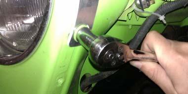
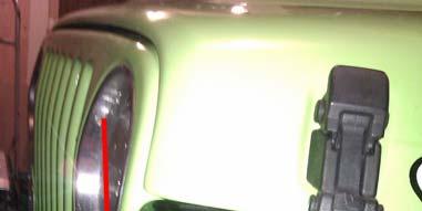
2 1. REMOVE THE OE TRIM, FLAIRS, AND HOOD LATCHES Remove all remnants of the OE plastic flair/marker lights, hood latches, and rubber hood stops. The rubber hood stops will not be reused. The nut-serts on the sides of the Jeep can also be removed if desired. We have had good luck with the removal of the nut-serts by grinding the heads off, and then using a hammer and punch to knock the nut-serts inward, or drill them out. 2. REMOVE THE 3 BOLTS HOLDING THE OE FENDER TO GRILLE Remove the 3 forward bolts that vertically run down the sides of the grille. 3. MARK YOUR TRIM LINE Using a pair of scissors, carefully cut out the paper template on the outside edge of the lines (the lines should still be visible on the template once it is cut out). Once the template is cut out, place it on top of the OE Jeep fender so that the hood latch holes line up. The solid line should be touching, over very close to touching, the ridge of sheet metal that separates the inner and out fender. A few pieces of tape will aid in holding the template in place while tracing. Trace along the dotted line. At the rear of the template, continue drawing the line down to meet the back edge of the wheel well, ending the line at the point where the back edge of the wheel well starts to curve towards the front of the Jeep. Refer to Fig. 1 and note the drawn line to help explain. Fig. 1

3 Also, refer to Fig. 2 for an example of how the cut needs to be made. Fig CUT ALONG YOUR LINES Using a reciprocating saw, cut-off wheel, or any cutting tool of your choice, cut along the lines which you have just drawn. Once completed, we recommend filing any sharp edges and applying primer paint to the exposed metal surfaces. This prevents rust and makes the job more professional. Be conservative with your cutting. Remember, you can always trim more if needed. 5. INSTALL THE RUBBER GROMMET AND SPACER In the large hole towards the bottom of the MCE fender, push the rubber grommet in place. Once the grommet is in place, push the spacer into the hole so that it is flush on the outer surface. 6. MARK AND DRILL HOLE FOR LOWER BRACKET AND FASTENERS Install the angle bracket onto the MCE fender by running the 1 button head fastener through the grommet/spacer, then slotted hole on the bracket, and use a washer and nut. Tighten just so there is no more slop, and make sure the side of the bracket which will attach to the Jeep is flush with the edge of the fender. Place the MCE fender
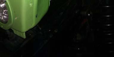
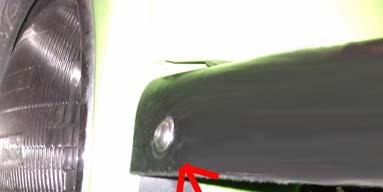
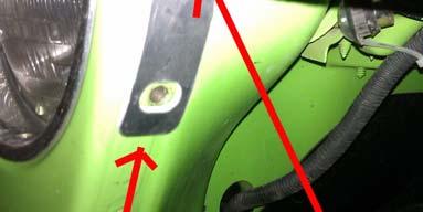
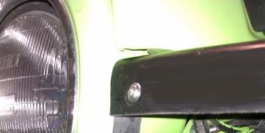
4 onto the OE fender and install the hood latch snugly. Make sure the MCE fender is sitting on the Jeep properly (push inward if needed), then with a pen mark where the hole needs to be drilled. Remove the MCE fender for drilling the hole. However, before removing the fender, mark the rest of the holes. With the fender then removed, center punch the holes and drill to ¼ diameter. Install the angle bracket to the body with a ¾ button head bolt. 7. INSTALL GRILLE BRACKET Place MCE fender back on OE fender, then: Refer to Fig. 3: hold grille bracket so that the large slotted hole at the bottom is centered up and down over the bolt hole on the side of the grille, and the wing of the bracket extends over the front surface of the fender. Next, make sure the wing of the bracket falls on the center of the flat surface of the fender (between bottom of the top radius and bottom edge of fender). Slight downward pressure on the MCE fender may be required, such as in Fig. 3. Mark the center of the slotted hole where it falls on the surface of the MCE fender. Remove the bracket and drill the MCE fender with a ¼ drill bit. (Center punch the hole for accuracy!) Next, refer to Fig. 4: attach the grille bracket to the inside of the front surface of the MCE fender using a ¾ long button head fastener, and use the wing nut to fasten by hand. Next, refer to Fig 4, 5, 6 and 7: with the grille bracket attached to the fender, line it up with the hole on the side of the grille (downward pressure may be required again). Install the OE 13mm bolt, making sure to use caution when tightening that the grille bracket allows the front surface of the fender to fall where it naturally wants to. The grill bracket may hold slight downward pressure on the MCE fender, however, it should not preload the surface in any other way. Doing so will cause the fender to not look right. From the side, look down the front of the fender and there should not be any visual warpage due to the bracket preloading the front surface. Due to tolerances of different Jeeps, the grille bracket is aluminum and the wing can be easily modified with channel locks/hammer/vice in order to conform to the MCE fender properly, if need be. A few minutes of extra time here if need be will ensure a proper looking and functioning fender. (Figures on next page)


5 Fig. 3 Fig. 4 Fig. 5 Fig. 6


6 Fig Install Flare Backing Strip This plastic strip goes on the side of the OE fender, and up against the inside of the MCE flare where it meets the body behind the tire. With the MCE fender sitting on the OE fender, place the backing strip so that it touches the inside of the flare, and slide it down the side of the Jeep until it makes contact with the MCE angle bracket. Mark the location of the backing strip, and remove the MCE fender one last time. With the MCE fender out of the way and the backing strip held in place with your marks, drive in 3 each of the self tapping screws, evenly spaced over the strip. 9. INSTALL FENDER Place the MCE fender back on the OE fender and install the fasteners and hood latch. The longer countersunk fasteners go in the area where the OE fender has a 2 nd layer of sheet metal. We recommend that the fasteners are not tightened fully until all of them are installed, in order to aid in everything lining up. The grille bracket bolts may utilize the wing nuts in order to be quickly removed on the trail for full fender flexibility. If the supplied nylock nuts are used, only tighten to just barely snug.

7 Fig. 8 Move to the next side and install in the same manner. Congratulations, you are done! Thanks again for your business!
YJ DeFenders. These installation instructions apply to the following Poison Spyder products:
 INSTALLATION INSTRUCTIONS INST-13-02-070_A YJ DeFenders IMPORTANT: Thank you for purchasing this Poison Spyder product. Please read through this entire document before proceeding with installation. If
PROVEN WORLDWIDE SNORKEL FOR CHEVY COLORADO NEW PRODUCT
 AEV30272AC Last Updated: 10/09/18 PROVEN WORLDWIDE SNORKEL FOR CHEVY COLORADO NEW PRODUCT Please visit www.aev-conversions.com to view the most current installation guide for this product. This is a new
JK Front Crusher Flares
 INSTALLATION INSTRUCTIONS INST-17-03-030_A JK Front Crusher Flares IMPORTANT: Thank you for purchasing this Poison Spyder product. Please read through this entire document before proceeding with installation.
Jeep Cherokee Door XJ Set Part # Revision J
 Jeep Cherokee 84-96 4 Door XJ Set Part # 10911 Revision J 6-5-06 Step 1: Prior to Installation: A) Fit: Verify the fit of the flares to vehicle. (Some filing, sanding, or cutting may be necessary to ensure
JK Rear Crusher Flares
 INSTALLATION INSTRUCTIONS INST-17-05-010_A JK Rear Crusher Flares IMPORTANT: Thank you for purchasing this Poison Spyder product. Please read through this entire document before proceeding with installation.
Jeep Cherokee 4-Door XJ Set Part # Rev
 Jeep Cherokee 4-Door XJ Set Part # 10911 Rev-14 04-05-10 Step 1: Prior to Installation: A) Bushwacker only approves installing the flares according to these written instructions with the hardware provided.
Installation for Full Size Polaris Ranger Crew Doors
 Installation for Full Size Polaris Ranger Crew Doors Order of Installation: Heater Doors Wiper on to Windshield Windshield Top & Back Panel Note: Most of the steps in these instructions need to be repeated
CUT OUT FLARES INSTALLATION INSTRUCTIONS FOR 20017, 20018, F100-F150 F250-F350 P.U. & BRONCO CUT OUTS
 20017 04/22/03 REV-A CUT OUT FLARES INSTALLATION INSTRUCTIONS FOR 20017, 20018, F100-F150 F250-F350 P.U. & BRONCO CUT OUTS Tools Required for Installation: (A) 3/16 Drill Bit (B) Pop-Rivet Gun (C) Air
BOX-117 E-Z-Go RXV Utility Box Mounting Kit Installation Instructions
 BOX-117 E-Z-Go RXV Utility Box Mounting Kit Installation Instructions Contents of BOX-117 Utility Box Mounting Kit: a (1 ea.) Utility Box Support Frame, Driver Side b (1 ea.) Utility Box Support Frame,
JK Rear Inner Fenders
 INSTALLATION INSTRUCTIONS INST-17-05-080_A JK Rear Inner Fenders IMPORTANT: Thank you for purchasing this Poison Spyder product. Please read through this entire document before proceeding with installation.
Bushwacker Jeep Flat Style Fender Flares Front Pair
 Bushwacker Jeep Flat Style Fender Flares Front Pair Note: These instructions involve cutting parts of your vehicle. Please read all instructions prior to starting. Installation Time: 3-4 Hours Tools Required:
Parts and tools needed for installation- Cleaning and Painting -
 Thank you for the purchase of our JK Rear Trail Doors. We have made these from 6061-T6 aluminum and reinforced them with stiffeners at the top that double as a comfortable armrest and support for Rugged
4-Door Rear XHD Armor Fenders
 Page 1/10 Part #11615.02 Page 2/10 1 4 2 3 5 Components 1. Left Rear Fender (1) 2. Right Rear Fender (1) 3. Left Rear Guard (1) 4. Right Rear Guard (1) 5. License Plate Bracket (1) OMIX-ADA TECHNICAL SUPPORT
JK FRONT FENDER FLARE INSTALLATION INSTRUCTIONS
 JK FRONT FENDER FLARE INSTALLATION INSTRUCTIONS TOOLS NEEDED 3/16 Allen Wrench 1/2 Socket or wrench 10mm Socket Flat head screwdriver HARDWARE 5/16 x 3/4 button heads (14) 5/16 x 1 button heads (8) 5/16
Included in Hardware Kit. Jeep Cut-Out Fender Flare Set of 4 Set Part # Rev STEP 1 PRIOR TO INSTALLATION
 Jeep Cut-Out Fender Flare Set of 4 Set Part #10926-07 Rev-01 09-11-12 STEP 1 PRIOR TO INSTALLATION A) Bushwacker only approves installing the flares according to these written instructions with the hardware
Introduction. Rocky Mountain Westy Swing Away Carrier Kit Installation Instructions
 Rocky Mountain Westy Swing Away Carrier Kit Installation Instructions Introduction Thank you for purchasing the Rocky Mountain Westy Swing Away Carrier Kit. We pride ourselves in the products we develop
JEEP JK ( 3 DOOR ) SLIMLINE II - FULL TRAY EXTREME RACK KIT
 SLIMLINE II - FULL TRAY EXTREME RACK KIT") JEEP JK ( 3 DOOR ) SLIMLINE II - FULL TRAY EXTREME RACK KIT FAJK004 / KRJW016T INSTALL TIME: 2 Hours NOTE: Your Jeep JK (3 Door) Extreme Roof Rack Kit consists of four boxes. (1) the Tray, (2) the Roll
JEEP JK ( 3 DOOR ) SLIMLINE II - FULL TRAY EXTREME RACK KIT FAJK004 / KRJW016T INSTALL TIME: 2 Hours NOTE: Your Jeep JK (3 Door) Extreme Roof Rack Kit consists of four boxes. (1) the Tray, (2) the Roll
Toyota FJ Cruiser 2006-Up Set Part # Revision A
 Toyota FJ Cruiser 2006-Up Set Part # 31924 Revision A 03-31-08 Step 1: Prior to Installation: A) Fit: Verify the fit of the flares to vehicle. (Some filing, sanding, or cutting may be necessary to ensure
BOX-118 E-Z-Go TXT Utility Box Mounting Kit Installation Instructions
 BOX-118 E-Z-Go TXT Utility Box Mounting Kit Installation Instructions Contents of BOX-118 Utility Box Mounting Kit: a (1 ea.) Utility Box Support Frame, Driver Side b (1 ea.) Utility Box Support Frame,
Cut-Out Fender Flares Rear Pair. Jeep. Included in Hardware Kit:
 Jeep Cut-Out Fender Flares Rear Pair STEP 1 PRIOR TO INSTALLATION A) Bushwacker only approves installing the fl ares according to these written instructions with the hardware provided. WARNING: Failure
INSTALLATION INSTRUCTIONS FOR & Chevy CUT OUT FLARE
 40009 7/10/03 REV-A INSTALLATION INSTRUCTIONS FOR 40009 & 40010 Chevy CUT OUT FLARE TOOLS REQUIRED FOR INSTALLATION: Drill Motor Pop Rivet Gun Flat File Hair Dryer or Heat Gun Sawzall Jack and Jack Stands
METRICFATS.COM Thank you for purchasing your new Stealth Rear Turn Signals for your Yamaha Raider.
 METRICFATS.COM Thank you for purchasing your new Stealth Rear Turn Signals for your Yamaha Raider. The instructional sheets that follow are thoroughly detailed and should be studied BEFORE picking up a
FENDER FLARE INSTALLATION
 Customer Support TM FENDER FLARE INSTALLATION TG-FF8C4108 IMPORTANT TYGER only approves the installation according to our instructions with the hardware provided. WARNING Failure to complete the installation
TIRE RACK INSTALLATION INSTRUCTIONS Dodge Sprinter
 Aluminess Products Inc 9402 Wheatlands Ct. #A Santee, CA 92071 619-449-9930 TIRE RACK INSTALLATION INSTRUCTIONS 07-11 Dodge Sprinter Please read before beginning Stainless steel hardware may bind together
2016 Current Toyota Tacoma HoneyBadger Front Bumper Installation Instructions
 2016 Current Toyota Tacoma HoneyBadger Front Bumper Installation Instructions PREPARATION 1. Disconnect the negative terminal on the battery. Park the vehicle on level ground and set the emergency brake.
JK Brawler Rockers. *Includes ONE of the Hardware Kits (not both)
") INSTALLATION INSTRUCTIONS INST-17-08-200_A JK Brawler Rockers IMPORTANT: Thank you for purchasing this Poison Spyder product. Please read through this entire document before proceeding with installation.
INSTALLATION INSTRUCTIONS INST-17-08-200_A JK Brawler Rockers IMPORTANT: Thank you for purchasing this Poison Spyder product. Please read through this entire document before proceeding with installation.
FENDER FLARE INSTALLATION
 TG-FF8T4178: Fit 2014-UP Toyota Tundra PRIOR TO INSTALLATION IMPORTANT Tyger only approves the installation according to our instructions with the hardware provided. WARNING Failure to complete the installation
JEEP JK ( 3 DOOR ) SLIMLINE II - FULL TRAY EXTREME RACK KIT
 SLIMLINE II - FULL TRAY EXTREME RACK KIT") JEEP JK ( 3 DOOR ) SLIMLINE II - FULL TRAY EXTREME RACK KIT FAJK005 / KRJW016T INSTALL TIME: 5 Hours NOTE: Your Jeep JK (3 Door) Extreme Roof Rack Kit consists of four boxes. (1) the Tray, (2) the Roll
JEEP JK ( 3 DOOR ) SLIMLINE II - FULL TRAY EXTREME RACK KIT FAJK005 / KRJW016T INSTALL TIME: 5 Hours NOTE: Your Jeep JK (3 Door) Extreme Roof Rack Kit consists of four boxes. (1) the Tray, (2) the Roll
TOOL LIST FOR TAILGATE HIDDEN LATCH & LINK ASSY FOR FORD FLARESIDE TRUCKS
 TOOL LIST FOR TAILGATE HIDDEN LATCH & LINK ASSY FOR 53-87 FORD FLARESIDE TRUCKS Vise Grip Clamps C-clamps Sharpie Marker Ball Peen Hammer Center Punch 3/8 or 1/2 Drill 5/32, 7/32, 9/32, and 3/8 Drill Bits
Bushwacker Jeep Flat Style Fender Flares Rear Pair (JK Wrangler 2dr)
") Bushwacker Jeep Flat Style Fender Flares Rear Pair (JK Wrangler 2dr) Note: These instructions involve cutting parts of your vehicle. Please read all instructions prior to starting. Installation Time: 3-4
Bushwacker Jeep Flat Style Fender Flares Rear Pair (JK Wrangler 2dr) Note: These instructions involve cutting parts of your vehicle. Please read all instructions prior to starting. Installation Time: 3-4
ASSEMBLY & INSTALLATION GUIDE
 ASSEMBLY & INSTALLATION GUIDE APPLICATION GM Truck (Full-size Trucks) PART # 74805-00A (Silver) 74805-0A(Black) INSTALLATION TIME Hour SKILL LEVEL 2 3 4 = Easy TOOLS REQUIRED Phillips screw driver Torx
INSTALLATION INSTRUCTIONS
 INSTALLATION INSTRUCTIONS SNYPER TUBULAR FENDERS APPLICATION: 2007-2017 Jeep Wrangler JK PART NUMBER: 62-1005, 62-1015 ITEM QUANTITY DESCRIPTION TOOLS NEEDED 1,2 2 FRONT FENDERS, DRIVER (1) AND PASSENGER
Jeep. Cut-Out Fender Flares Set of 4. Included in Hardware Kit: Set Part # Rev-8 06/29/16 STEP 1 PRIOR TO INSTALLATION
 STEP 1 PRIOR TO INSTALLATION A) Bushwacker only approves installing the flares according to these written instructions with the hardware provided. WARNING: Failure to install according to these instructions
Rubber Grommet, 36 pcs. 3/4 Screw, 10 pcs. Nut, 10 pcs
 Jeep Cherokee ZJ Set Part #10916-07 Rev-2 03-11-10 THESE INSTRUCTIONS INVOLVE CUTTING THE FENDERS OF THE VEHICLE. IT IS IMPORTANT TO READ ALL INSTRUCTIONS PRIOR TO THE CUTTING AND INSTALLATION OF THESE
Install. Jeep JK Adventure Tire Carrier. Tools Needed. Hardware
 Jeep JK Adventure Tire Carrier Thank you for purchasing the Adventure upper tire carrier from JcrOffroad! Checkout our website, www.jcroffroad.com for more deals and other great off road products. Please
Drake Off Road Hood Hold Downs Installation Guide
 Installation Time: 30 Minutes Tools Required: Drake Off Road Hood Hold Downs Installation Guide 3/8 drive ratchet 13mm socket 10mm socket (deep-well socket helpful) 13mm wrench (2x) 4mm allen wrench 5mm
Be sure any accessory used will fit with the soft upper doors before installing. Not all accessories will be compatible.
 Company Name: Spike Power Sports Vehicle Name: Polaris General 2P Product Description: Soft Upper Doors Part Number: 58-1600 Revision: R01 09/19/2018 Contents: 655 Elm Ridge Ave, Canal Fulton OH, 44614
Assembly Instructions 10 X 10 Aluminum Roof Support
 Assembly Instructions 10 X 10 Aluminum Roof Support Aluminum Roof Support Bolt Package 16-5/16 X 2 ¼ SS Bolt 24-5/16 X 1 SS Bolt 40-5/16 SS Nylon Lock Nuts 16-5/16 SS Flat Washers 28-4 ½ Wood Screws 36-1
Bolt-On/Rugged Fender Flares Toyota Tundra (14-ON) Important: Please read instructions entirely before installing this product.
 Important: Please read instructions entirely before installing this product.") Important: Please read instructions entirely before installing this product. Hardware Included QTY Hardware Included QTY Bolt Kit Included QTY Extrusion 28.0 ft Short Screw 18 Nuts 42 Alcohol Wipe 4 Long
Important: Please read instructions entirely before installing this product. Hardware Included QTY Hardware Included QTY Bolt Kit Included QTY Extrusion 28.0 ft Short Screw 18 Nuts 42 Alcohol Wipe 4 Long
Installing a genuine HoodLift on a Jeep TJ
 Installing a genuine HoodLift on a Jeep TJ 1997-2006 To print a full-color version of these instructions go to www.hoodlift.com/products.html. Scroll down to the TJ HoodLift and click on the TJ HoodLift
JK Crusher Corners. *Includes ONE of the Hardware Kits (not both)
") INSTALLATION INSTRUCTIONS INST-18-05-020_A JK Crusher Corners IMPORTANT: Thank you for purchasing this Poison Spyder product. Please read through this entire document before proceeding with installation.
INSTALLATION INSTRUCTIONS INST-18-05-020_A JK Crusher Corners IMPORTANT: Thank you for purchasing this Poison Spyder product. Please read through this entire document before proceeding with installation.
Giraud Tool Company, Inc.
 Motor Upgrade for Gracey Trimmer This package is intended to allow the user to upgrade their Gracey trimmer with a higher rpm motor and convenience features not found in the production offering. This upgrade
Jeep. Cut-Out Fender Flares Set of 4. Included in Hardware Kit:
 STEP 1 PRIOR TO INSTALLATION A) Bushwacker only approves installing the fl ares according to these written instructions with the hardware provided. WARNING: Failure to install according to these instructions
Jeep Wrangler JK & 4-Door Front Pair Part # Revision H
 Jeep Wrangler JK 2007 2 & 4-Door Front Pair Part # 10045 Revision H 03-25-09 Step 1: Prior to Installation: A) Bushwacker only approves installing the flares according to these written instructions with
Bulkhead Model Number and
 Bulkhead Model Number 96141-3-01 and 96142-3-01 Installing your ProMaster bulkhead is very clear cut following these instructions. Before cutting or drilling in the floor, verify the location of you gas
GENUINE PARTS INSTALLATION INSTRUCTIONS
 GENUINE PARTS INSTALLATION INSTRUCTIONS DESCRIPTION: APPLICATION: PART NUMBER: REAR SPOILER KIT - CARBON FIBER INFINITI Q60 T99J1 5CH0B KIT CONTENTS: Item Qty. Part Description A 1 Spoiler Assembly B 4
6625 WEST WILSHIRE BLVD. OKLAHOMA CITY, OK (405) FAX (405)
 FAX (405)") INSTALLATION INSTRUCTIONS FOR THE TAILGATE WITH LATCH AND LINK ASSEMBLY 76-87 FORD SHORT & 53-87 FORD LONG FLARESIDES 1. Assemble the bed and make sure the box is square. Measure the distance between the
INSTALLATION INSTRUCTIONS FOR THE TAILGATE WITH LATCH AND LINK ASSEMBLY 76-87 FORD SHORT & 53-87 FORD LONG FLARESIDES 1. Assemble the bed and make sure the box is square. Measure the distance between the
JEEP JK ( 5 DOOR ) SLIMLINE II - FULL TRAY EXTREME RACK KIT
 SLIMLINE II - FULL TRAY EXTREME RACK KIT") JEEP JK ( 5 DOOR ) SLIMLINE II - FULL TRAY EXTREME RACK KIT FAJK001 / KRJW014T INSTALL TIME: 2.5 Hours NOTE: Your Jeep JK (5 Door) Extreme Roof Rack Kit consists of four boxes. (1) the Tray, (2) the Roll
JEEP JK ( 5 DOOR ) SLIMLINE II - FULL TRAY EXTREME RACK KIT FAJK001 / KRJW014T INSTALL TIME: 2.5 Hours NOTE: Your Jeep JK (5 Door) Extreme Roof Rack Kit consists of four boxes. (1) the Tray, (2) the Roll
Rugged Ridge Engine Transmission Skid Plate JK
 Installation Time: 1-2 Hours Tools Required: Rugged Ridge Engine Transmission Skid Plate 2012-2017 JK Sockets: 16mm, 17mm, 18mm deep well Socket Wrench Wrenches: 16mm, 18mm Torque Wrench Drill ½ Drill
INSTALL LOAD BED TRACKS
 Universal LOAD BED TRAY & Load BArs TRBU001 / KRLBUNI1 INSTALL TIME: 2.5 Hours READ ME FIRST: Thank you for purchasing a Front Runner Slimline II Load Bed Rack or Load Bar Kit. Your Kit will contain the
RangerWare Fiberglass Door System Installation Instructions P/N
 Page 1 of 9 RangerWare Fiberglass Door System Installation Instructions P/N 2878016 ORDER OF INSTALLATION Note: To assure proper order, read all Accessory Installation Instructions before beginning. 1.
VACUSEAL MODEL 200. HOT TUB PRODUCTS 233 Carrington Road Bethany CT
 VACUSEAL MODEL 200 J G F G H L HOT TUB PRODUCTS 233 Carrington Road Bethany CT 06524 860-469-2580 www.vacusealcoverlift.com www.hottubproducts.com Made in USA H K E D C I A P B 10 9 8 7 6 5 4 3 2 1 0 SPAS
Master Your Terrain. (307)
") Master Your Terrain (307) 775 9565 www.tntcustoms.com Rear Swing-out Tire Carrier Jeep TJ/LJ Installation Instructions Congratulations for purchasing a T&T Customs, Inc. Rear Swing-out Tire Carrier for
Master Your Terrain (307) 775 9565 www.tntcustoms.com Rear Swing-out Tire Carrier Jeep TJ/LJ Installation Instructions Congratulations for purchasing a T&T Customs, Inc. Rear Swing-out Tire Carrier for
MITSUBISHI PAJERO CK LONG WHEEL BASE 2100 MM TRACKS TRMP001
 MITSUBISHI PAJERO CK LONG WHEEL BASE 2100 MM TRACKS TRMP001 INSTALL TIME: 1.2 Hours IMPORTANT WARNING! IT IS CRITICAL THAT ALL FRONT RUNNER PRODUCTS BE PROPERLY AND SECURELY ASSEMBLED AND ATTACHED TO YOUR
08+ KAWASAKI KLR PD NERF
 08+ KAWASAKI KLR PD NERF 0505-1299 Before you begin, place the bike on a hard level surface where you have room to work. Lay out the parts included in this kit and compare to the parts list on page 5 of
Ford Ranger / Bronco II Set Part # Rev B 5-04
 Ford Ranger / Bronco II Set Part # 21008 Rev B 5-04 Step 1: Prior to Installation: A) Fit: Verify the fit of the flares to vehicle. (Some filing, sanding, or cutting may be necessary to ensure proper fit).
10" E-Series D-Series - Pair. kit includes (14) (4) (4) It is strongly recommended that this product be installed by a professional.
 (4) (4) It is strongly recommended that this product be installed by a professional.") 2014 GMC 1500 grille installation instructions 10" E-Series D-Series - Pair kit includes (14) (14) (4) 5 /16-18x 5 /8 Button Socket 5 /16-18 Low Profile Nylock Nut M6-1.0x30mm Button Head Socket (14) (4)
2014 GMC 1500 grille installation instructions 10" E-Series D-Series - Pair kit includes (14) (14) (4) 5 /16-18x 5 /8 Button Socket 5 /16-18 Low Profile Nylock Nut M6-1.0x30mm Button Head Socket (14) (4)
HDL(M)6 Nut/Screw Assembly
6 Nut/Screw Assembly") HDL(M)6 Nut/Screw Assembly Remove, repair, and reassemble the nut and screw assembly in your HDL series double lock vise. In these instructions when we refer to the front of the vise or nut/screw assembly,
HDL(M)6 Nut/Screw Assembly Remove, repair, and reassemble the nut and screw assembly in your HDL series double lock vise. In these instructions when we refer to the front of the vise or nut/screw assembly,
Otter Pro XT Cottage Installation and Set-Up Instructions
 Otter Pro XT Cottage Installation and Set-Up Instructions Otter Pro XT Cottage Fits Small Ultra-Wide Otter Pro and Otter II Sled Only Parts Identification and Check List MODEL NUMBERS: Complete Pkg Pro
Ford F150 Front Bumper
 2009-2011 Ford F150 Front Bumper Warning! Read the instructions completely before beginning the installation. Before tightening bolts, drilling or cutting where required, check to make sure that there
KAWASAKI KLRE PD NERF HTP4-8-5 & HIGHWAY PEGS HTP4-1-4B
 Thank you for purchasing Happy Trails products. Our products are proudly hand made in Boise Idaho, USA. If you have any questions or concerns about the installation of this product, please contact us directly
Fortress Fe Posts must always be secured to the deck framing. Fortress Fe Posts should never be attached to only the deck boards.
 Installation Instructions for Fortress Horizontal Cable Panel System with UB-05 Brackets and Fe Posts It is the responsibility of the installer to meet all code and safety requirements, and to obtain all
Breathable Wall Light Traps & Blackout Fan & Shutter Kits
 Breathable Wall Light Traps & Blackout Fan & Shutter Kits 2017 Growers Supply All Rights Reserved. Reproduction is prohibited without permission. Maintain controlled airflow without sacrificing blackout
INSTALLATION GUIDE PREMIUM FRONT BUMPER. AEV30103AE Last Updated: 09/08/14 US PATENTS: D683281, D CHINESE PATENT: ZL
 PREMIUM FRONT BUMPER US PATENTS: D683281, D697842 CHINESE PATENT: ZL 2012 3 0026081.4 AEV30103AE Last Updated: 09/08/14 INSTALLATION GUIDE PLEASE READ BEFORE YOU START TO GUARANTEE A QUALITY INSTALLATION,
STYLE BAR & TONNEAU COVER INSTALLATION
 STYLE BAR & TONNEAU COVER INSTALLATION INSTALLATION MANUAL: 2005 to '09 Mustang P/N: 10-8002-C12071B Saleen Performance, Inc. 1225 East Maple Rd., MI 48083 800-888-8945 www.saleen.com 1 IF YOU ARE NOT
Box Track INSTALLATION INSTRUCTIONS
 Box Track INSTALLATION INSTRUCTIONS BOX TRACK Recommended Tools Level Tape Measure Pencil Drill with 1/8, and 1/4, Drill Bits, Phillips Bit and Slotted Bit Socket Wrench with 9/16 Socket 9/16 and 5/8 Wrench
Chevy Colorado. INSTALLATION GUIDE Front Bumper
 Chevy Colorado INSTALLATION GUIDE Front Bumper FIG 1A First, we ll start by removing the small allen bolts from the inside fender wells that hold the stock front bumper in place. FIG 1B You will also need
All Terrain Flares 2014 Chevy Silverado
 Page 1/8 Components: 1. Front Flares (2) 2. Rear Flares (2) Tools required: - Utility knife - #2 Phillips driver - Socket wrench - 13 mm Socket - 6 mm Allen Wrench - T-15 Torx bit - Trim Removal Tool -
BOX-115 Club Car Precedent Utility Box Mounting Kit Installation Instructions
 BOX-115 Club Car Precedent Utility Box Mounting Kit Installation Instructions Contents of BOX-115 Utility Box Mounting Kit: a (1 ea.) Utility Box Support Frame, Passenger Side b (1 ea.) Utility Box Support
Rockwell 4-in-1 Sliding Door
 Rockwell 4-in-1 Sliding Door ASSEMBLY INSTRUCTIONS ROCKWELL 4-IN-1 SLIDING DOOR Recommended Tools Drill with Phillips Bit Socket Wrench with 7/16 Socket Rubber Mallet Adjustable Square ROCKWELL 4-IN-1
Elite Series Fender Flares
 Page 1 of 8 Installation Instructions I - Sheet Number I606RPG Rev.B Important Safety Information Tools Required Contents Elite Series Fender Flares Preparation Before Painting / Installation NOTE Actual
JK TrailGate JK TrailGate
 INSTALLATION INSTRUCTIONS INST-17-66-010_A JK TrailGate IMPORTANT: Thank you for purchasing this Poison Spyder product. Please read through this entire document before proceeding with installation. If
Toyota Tacoma Extended Cab/Standard Cab Set Part # Rev
 Toyota Tacoma Extended Cab/Standard Cab Set Part # 31919 Rev-7 06-23-10 Step 1: Prior to Installation: A) Bushwacker only approves installing the flares according to these written instructions with the
Tools: Sharpie, Square, Vise, Hack saw, Ruler, Punch, Hammer, File. 2. Cut the stock Place stock in vise and cut with hack saw
 Purpose: MAKE CATAPULT ARM Step 1 Tools: Sharpie, Square, Vise, Hack saw, Ruler, Punch, Hammer, File Materials: Flat aluminum ½ inch stock (see picture below) Gloves required 1. Pick up the aluminum ½
SAFETY. Read and understand all safety precautions and instructions before installing this product.
 SAFETY Your safety and the safety of others is very important. In order to help you make informed decisions about safety, we have provided installation instructions and other information. These instructions
SEAT-361 E-Z-Go RXV RHOX Seat Kit Installation Instructions
 SEAT-361 E-Z-Go RXV RHOX Seat Kit Installation Instructions Contents of SEAT-361 RHOX 300 Series Rear Seat Kit: a (1 ea.) Front Seat Back Support, Driver Side b (1 ea.) Front Seat Back Support, Passenger
Assembly Instructions 10 X 10 Aluminum Frame Building
 Assembly Instructions 10 X 10 Aluminum Frame Building 27 97 9 8 47 36 74 52 10 10 X 10 Square Building W/ Dome Includes: The Steel Entry Door with a Dead Bolt Lock assembly and Aluminum Door Frame. Metal
Driver/Left Top. Support Bracket
 PARTS LIST: 1 Grille Guard 8 10mm Lock Washers 1 Driver/Left Frame Bracket 8 10mm Hex Nuts 1 Passenger/Right Frame Bracket 2 8-1.25mm x 25mm Button Head Bolts 1 Driver/Left Bottom Support Bracket 2 8mm
JK Body-Mounted Tire Carrier
 INSTALLATION INSTRUCTIONS INST-17-13-010_A JK Body-Mounted Tire Carrier IMPORTANT: Thank you for purchasing this Poison Spyder product. Please read through this entire document before proceeding with installation.
JK Body-Mounted Tire Carrier
 INSTALLATION INSTRUCTIONS INST-17-13-010_C JK Body-Mounted Tire Carrier IMPORTANT: Thank you for purchasing this Poison Spyder product. Please read through this entire document before proceeding with installation.
JEEP JK ( 5 DOOR ) SLIMLINE II - FULL TRAY EXTREME RACK KIT
 SLIMLINE II - FULL TRAY EXTREME RACK KIT") JEEP JK ( 5 DOOR ) SLIMLINE II - FULL TRAY EXTREME RACK KIT FAJK002 / KRJW014T INSTALL TIME: 5 Hours NOTE: Your Jeep JK (5 Door) Extreme Roof Rack Kit consists of four boxes. (1) the Tray, (2) the Roll
JEEP JK ( 5 DOOR ) SLIMLINE II - FULL TRAY EXTREME RACK KIT FAJK002 / KRJW014T INSTALL TIME: 5 Hours NOTE: Your Jeep JK (5 Door) Extreme Roof Rack Kit consists of four boxes. (1) the Tray, (2) the Roll
General Features. Low Profile. The SMART BOXX stands only 1.5 off of the bed of your truck so cargo space is maximized
 General Features Low Profile. The SMART BOXX stands only 1.5 off of the bed of your truck so cargo space is maximized Two Sizes Short Box :74 L X 47 W X 7 T and Long Box 92 L X 47 W X 7 T All Aluminium
Cellar Hanger ASSEMBLY INSTRUCTIONS
 Cellar Hanger ASSEMBLY INSTRUCTIONS CELLAR HANGER Recommended Tools Drill with 1/8 and 1/4 Drill Bits, 1-1/8 Forstner Bit or 1-1/8 Spade Bit, and Phillips Bit 9/16, 7/16, and 5/8 Combination Wrench Socket
Toyota Cut-Out TM Fender Flares Set of 4
 Toyota Cut-Out TM Fender Flares Set of 4 STEP 1 PRIOR TO INSTALLATION A) Bushwacker only approves installing the fl ares according to these written instructions with the hardware provided. WARNING: Failure
1/4 Rubber Spacer, 26 pcs. M5-.8 Machine Screw, 26 pcs 13. Female Wire Connector, 4 pcs
 97-06 Jeep Wrangler TJ Set Part #10920-07 Rev-3 12-15-08 A) B) C) D) E) F) G) STEP 1 - PRIOR TO INSTALLATION Bushwacker only approves installing the fl ares according to these written instructions with
Pillar Hanger ASSEMBLY INSTRUCTIONS
 Pillar Hanger ASSEMBLY INSTRUCTIONS PILLAR HANGER Recommended Tools Drill with 1/8, 1/4, and 3/8 Drill Bits, 1-1/8 Forstner Bit or 1-1/8 Spade Bit, and Phillips Bit 9/16 and 5/8 Combination Wrench Socket
M10 x 75mm Sockethead Cap Screws. 5mm Fender Washer (12) Included - (8) Required. #10 x 2.5" PH Wood Screws. (30) Included - (24) Required
 Included - (8) Required. #10 x 2.5 PH Wood Screws. (30) Included - (24) Required") Door System Unit - Hardware Tools Included: (2) 2mm Allen Wrenches, (2) 3mm Allen Wrenches, (2) 4mm Allen Wrenches, (2) 6mm Allen Wrenches, and (1) 8mm T-Handle Allen Wrench Tools Required: Phillips Screwdriver,
Door System Unit - Hardware Tools Included: (2) 2mm Allen Wrenches, (2) 3mm Allen Wrenches, (2) 4mm Allen Wrenches, (2) 6mm Allen Wrenches, and (1) 8mm T-Handle Allen Wrench Tools Required: Phillips Screwdriver,
RLP Flat Track Hardware sliding door hardware/ barn door track
 Page 1 of 9 Installation Suggestions for: RLP Flat Track Hardware sliding door hardware/ barn door track Read these instructions to end before starting installation or ordering hardware. Reclaimed Lumber
INSTALLATION INSTRUCTIONS
 INSTALLATION INSTRUCTIONS Trans4mer Grille Guard/Winch Mount Kit 645 For Chevrolet Silverado 500HD & 3500 This WARN Trans4mer system can be customized to give your Chevy Silverado a wide variety of looks,
Jeep. Cut-Out Fender Flares Set of 4. Included in Hardware Kit: Set Part # Rev-6 7/20/15 For complete fitment info visit :
 Jeep Cut-Out Fender Flares Set of 4 STEP 1 PRIOR TO INSTALLATION A) Bushwacker only approves installing the fl ares according to these written instructions with the hardware provided. WARNING: Failure
Fortress Fe Posts must always be secured to the deck framing. Fortress Fe Posts should never be attached to only the deck boards.
 Installation Instructions for FortressCable H-Series Cable Panel System With UB-05 Brackets and Fe Posts It is the responsibility of the installer to meet all code and safety requirements, and to obtain
STEP 1 : DESTROYER FRONT BUMPER INSTALL GATHER YOUR TOOLS AND LAY OUT YOUR PARTS... *shorty bumper to show hardware* Tools Required:
 DESTROYER FRONT BUMPER INSTALL JL STEP 1 : GATHER YOUR TOOLS AND LAY OUT YOUR PARTS... Tools Required: - Utility knife - 11/16 Deep socket - Ratchet - 11/16 Crescent wrench - Ratchet Extension - 1/4 socket
Workbench Instructions for Assembly
 Workbench Instructions for Assembly Technical Electronic Workstations and Industrial Workbenches Includes: Cabinets Privacy Panels Stringers Bottom Shelves Table of Contents Tools Required for Assembly...
Installation Instructions
 For Medium (15-18.5K) + Heavy duty (22-28.5K) Air Conditioner READ BEFORE INSTALLING UNIT To avoid risk of personal injury, property damage, or product damage due to the weight of this device and sharp
JEEP XJ CRUSADER ROCK SLIDERS INSTALL INSTRUCTIONS
 JEEP XJ CRUSADER ROCK SLIDERS INSTALL INSTRUCTIONS Please read the mounting instructions below carefully before attempting to install. Thank you for purchasing your new armor from JcrOffroad! Checkout
MODULAR BUMPER INSTALLATION MANUAL
 MODULAR BUMPER INSTALLATION MANUAL Parts List* 1 Center section 1 Side extension, passenger / right 1 Side extension, driver / left 1 Side cap, passenger / right 1 Side cap, driver / left 1 Brush guard,
INSTALLATION INSTRUCTIONS: ULTRA FRONT FENDER FLARES
 INSTALLATION INSTRUCTIONS: ULTRA FRONT FENDER FLARES Thank you for your purchase of Crawler Conceptz Ultra Series Front Fender Flares. While these flares are easily installed with basic hand tools and
Industrial Hanger ASSEMBLY INSTRUCTIONS
 Industrial Hanger ASSEMBLY INSTRUCTIONS INDUSTRIAL HANGER Recommended Tools Drill with 1/8, 1/4, and 3/8 Drill Bits, 1-1/8 Forstner Bit or 1-1/8 Spade Bit, and Phillips Bit 9/16 and 5/8 Combination Wrench
RH-412 STEEL DOORS INSTALLATION INSTRUCTIONS
 RH-412 STEEL DOORS INSTALLATION INSTRUCTIONS By following the steps outlined below, the assembly, installation and adjustment of the steel doors, will be a simple process. Let s start with the Driver Side.
2010+ Dodge Ram 2500/3500 Front Bumper Install Instructions
 2010+ Dodge Ram 2500/3500 Front Bumper Install Instructions Warning! Read the instructions completely before beginning the installation. Before tightening bolts, drilling or cutting where required, check