Foundations & Installing Tools for Transmission & Substations
|
|
|
- Howard Webb
- 6 years ago
- Views:
Transcription


1 Foundations & Installing Tools for Transmission & Substations 4B Page 4B-1
2 DISCLAIMER The information in this manual is provided as a guide to assist you with your design and in writing your own specifications. Installation conditions, including soil and structure conditions, vary widely from location to location and from point to point on a site. Independent engineering analysis and consulting state and local building codes and authorities should be conducted prior to any installation to ascertain and verify compliance to relevant rules, regulations and requirements. Hubbell, Inc., shall not be responsible for, or liable to you and/or your customers for the adoption, revision, implementation, use or misuse of this information. Hubbell, Inc., takes great pride and has every confidence in its network of dealers/installing contractors. Hubbell, Inc., does NOT warrant the work of its dealers/installing contractors in the installation of CHANCE Civil Construction foundation support products. Page 4B-2
3 TABLE OF CONTENTS SECTION DESCRIPTION PAGE Square Shaft (SS) Products Introduction to Round and Square Shaft 4B-4 Square Shaft (SS) Product Ratings, Section Properties and Mechanical Strength 4B " Round Corner Square Shaft (SS5 Series) 4B " Round Corner Square Shaft (SS150 Series) 4B " Round Corner Square Shaft (SS175 Series) 4B-9 2" Round Corner Square Shaft (SS200 Series) 4B " Round Corner Square Shaft (SS225 Series) 4B-11 Notes: 1 1 4" to 2 1 4" Square Bar Products 4B-12 CHANCE Helical Pulldown Micropiles, Displacement Plates 4B Round Shaft (RS) Products ing System for Helical Round Shaft Foundations 4B-15 Round Shaft (RS) Product Ratings, Section Properties and Mechanical Strength 4B " Round Shaft (RS Series) 4B " Round Shaft (RS Series) 4B " Round Shaft (RS Series) 4B " Round Shaft (RS Series) 4B " Round Shaft (RS Series) 4B " Round Shaft (RS Series) 4B-23 Notes: 2 7 8" to 8 5 8" OD Round (Pipe) Shaft Products 4B-24 Square Shaft & Round Shaft (SS/RS) Combinations 4B-25 Assemblies and Hardware CHANCE Helical New Construction Pile and Rebar Caps 4B-26 Grillages 4B-27 Installation Tools 4B Page 4B-3 Installing Tools Hardware SS/RS Combos Round Shaft Square Shaft
4 CHANCE HELICAL ANCHORS/PILES Square Shaft INTRODUCTION A helical anchor/pile is a segmented deep foundation system with helical bearing plates welded to a central steel shaft. Load is transferred from the shaft to the soil through these bearing plates. Central steel shafts are available in either Type SS (Square Shaft) series or Type RS (Round Shaft) series. The Type SS series are available in 1 1 2" to 2 1 4" square sizes. The Type RS series are available in 2 7 8" to 8 5 8" diameter sizes. Type SS-RS combinations are also available for compression applications in soil conditions where dense/hard soils must be penetrated with softer/loose soils above the bearing strata. The Helical Pulldown Micropile series is also used in applications similar to those requiring the use of the Type SS-RS combinations. Segments or sections are joined with bolted couplings. Installation depth is limited only by soil density and practicality based on economics. A helical bearing plate or helix is one pitch of a screw thread. All helices, regardless of their diameter, have a standard 3" pitch. Being a true helical shape, the helices do not auger into the soil but rather screw into it with minimal soil disturbance. Helical plates are spaced at distances far enough apart that they function independently as individual bearing elements; consequently, the capacity of a particular helix on a helical anchor/pile shaft is not influenced by the helix above or below it. Lead Section and Extensions The first section or lead section contains the helical plates. This lead section can consist of a single helix or up to four helices. Additional helices can be added, if required, with the use of helical extensions. Standard helix sizes are shown in Table 1. The helices are arranged on the shaft such that their diameters increase as they get farther from the pilot point. The practical limits on the number of helices per anchor/pile is four to five if placed in a cohesive soil and six if placed in a cohesionless or granular soil. Plain extensions are then added in standard lengths of 3, 5, 7 and 10 feet until the lead section penetrates into the bearing strata. Standard helix configurations are provided in the product series tables in this section. Note that lead time will be significantly reduced if a standard helix configuration is selected. STANDARD HELIX SIZES Table 1 LEAD SECTION AND EXTENSIONS DIAMETER in (cm) AREA ft 2 (m 2 ) 6 (15) (0.0172) 8 (20) (0.0312) 10 (25) (0.0493) 12 (30) (0.0716) 14 (35) (0.0974) 16 (40) (0.1286) Page 4B-4
5 CHANCE HELICAL ROUND CORNER SQUARE SHAFT PRODUCTS CHANCE Square Shaft (SS) Helical Product Ratings Table 2 Product Series Torque Rating ft-lbs (Nm) Ultimate Tension Strength* kip (kn) Uplift/Compression Capacity Limit** kip (kn) Square Shaft SS5 5,500 (7 500) 70 (312) 55 (245) SS150 7,000 (9 500) 70 (312) 70 (312) SS175 11,000 (14 900) 100 (445) 110 (489) SS200 16,000 (21 700) 150 (668) 150 (668) *** SS225 23,000 (31 200) 200 (890) 200 (890) *** * Based on Mechanical Strength of Coupling ** Based on Torque Rating Uplift/Compression Capacity Limit = Torque Rating x Kt. Default Kt for Type SS = 10 ft-1 (33 m-1) *** Based on Mechanical Strength of Coupling Bolt Higher Compression Capacities Available with Helical Pulldown Micropile CHANCE Square Shaft Helical Cross Sections Figure Page 4B-5
6 Square Shaft CHANCE Square Shaft (SS) Helical Section Properties Table 3 Product Series Shaft Size in (mm) Wall Thickness in (mm) Metal Area in 2 (cm 2 ) Perimeter in (cm) Moment of Inertia in 4 (cm 4 ) I x-x, I y-y, I x-y Section Modulus in 3 (cm 3 ) S x-x S y-y SS5 1.5 (38) solid 2.2 (14.2) 5.6 (14.2) 0.40 (16.5) 0.53 (8.7) 0.42 (6.9) S x-y SS (38) solid 2.2 (14.2) 5.6 (14.2) 0.40 (16.5) 0.53 (8.7) 0.42 (6.9) SS (44) solid 3.1 (19.4) 6.6 (16.7) 0.75 (31.1) 0.85 (13.9) 0.66 (10.8) SS200 2 (51) solid 3.9 (25.3) 7.5 (18.9) 1.26 (52.4) 1.26 (20.6) 0.98 (16.1) SS (57) solid 5.0 (32.1) 8.5 (21.5) 2.04 (84.9) 1.81 (29.7) 1.40 (22.9) CHANCE Square Shaft (SS) Helix Thickness and Mechanical Strength Table 4 Product Series ksi (mpa) DEFAULT (STANDARD) Thickness in (mm) Mechanical Strength kip (kn) ksi (mpa) OPTIONS Thickness in (mm) Mechanical Strength kip (kn) 50 (345) 1 2" (13) 45 (200) SS5 50 (345) 3 8" (9.5) 40 (178) 80 (552) 3 8" (9.5) 40 (178) 80 (552) 1 2" (13) 50 (222) SS (552) 3 8" (9.5) 40 (178) 50 (345) 1 2" (13) 45 (200) SS (552) 3 8" (9.5) 50 (222) 80 (552) 1 2" (13) 60 (267) SS (552) 1 2" (13) 60 (267) SS (552) 1 2" (13) 60 (267) The mechanical strength ratings in Table 4 are minimum values. The helix diameter, grade, and thickness along with the shaft series to which an individual helix is connected effect the mechanical strength rating of a helix. A higher mechanical strength rating of an individual helix is possible depending on the combination of these variables. Page 4B-6
7 CHANCE HELICAL 1 1 2" ROUND CORNER SQUARE SHAFT PRODUCTS (TYPE SS5 SERIES) COMMON LEAD CONFIGURATIONS Effective (See Notes Page 12) A B C D Length (in)* T AE AEJ AEJN T EJ EJN EJNS *Effective length: from leading edge of bottom helix to center of bolt hole. T after plate diameter means 1 2" thick helix. Square Shaft CHANCE HELICAL 1 1 2" ROUND CORNER SQUARE SHAFT PRODUCTS (TYPE SS5 SERIES) COMMON EXTENSION CONFIGURATIONS Plain Extension (See Notes Page 12) A B Effective Length (in)* Coating GALV GALV GALV GALV 12655J GALV 12656N GALV * Effective length: from bolt hole to bolt hole. Page 4B-7
8 CHANCE HELICAL 1 1 2" ROUND CORNER SQUARE SHAFT PRODUCTS (TYPE SS150 SERIES) Square Shaft COMMON LEAD CONFIGURATIONS (See Notes Page 12) A B C D Effective Length (in)* T C C T T C *Effective length: from leading edge of bottom helix to center of bolt hole. COMMON EXTENSION CONFIGURATIONS (See Notes Page 12) A B C Effective Length (in)* C C C C C C C * Effective length: from bolt hole to bolt hole. Page 4B-8
9 CHANCE HELICAL 1 3 4" ROUND CORNER SQUARE SHAFT PRODUCTS (TYPE SS175 SERIES) COMMON LEAD CONFIGURATIONS Square Shaft (See Notes Page 12) A B C D Effective Length (in)* C C C C T *Effective length: from leading edge of bottom helix to center of bolt hole. CHANCE HELICAL 1 3 4" ROUND CORNER SQUARE SHAFT PRODUCTS (TYPE SS175 SERIES) COMMON EXTENSION CONFIGURATIONS (See Notes Page 12) A B C Effective Length (in)* C C C C C C C * Effective length: from bolt hole to bolt hole. Page 4B-9
10 CHANCE HELICAL 2" ROUND CORNER SQUARE SHAFT PRODUCTS (TYPE SS200 SERIES) Square Shaft COMMON LEAD CONFIGURATIONS (See Notes Page 12) A B C D Effective Length (in)* C T 8T 10T C T 8T 10T 12T C T 10T 12T C T 10T 12T 14T C T 14T 14T *Effective length: from leading edge of bottom helix to center of bolt hole. T after plate diameter means 1 2" thick helix. COMMON EXTENSION CONFIGURATIONS (See Notes Page 12) A B C Effective Length (in)* C C C C C T C T 14T C T 14T 14T * Effective length: from bolt hole to bolt hole. T after plate diameter means 1 2" thick helix. Page 4B-10
11 CHANCE HELICAL 2 1 4" ROUND CORNER SQUARE SHAFT PRODUCTS (TYPE SS225 SERIES) COMMON LEAD CONFIGURATIONS Square Shaft (See Notes Page 12) A B C D Effective Length (in)* C T 8T 10T C T 10T 12T C T 10T 12T 14T C T 14T 14T *Effective length: from leading edge of bottom helix to center of bolt hole. T after plate diameter means 1 2" thick helix. COMMON EXTENSION CONFIGURATIONS (See Notes Page 12) A B C Effective Length (in)* C C C T C T 14T * Effective length: from bolt hole to bolt hole. T after plate diameter means 1 2" thick helix. Page 4B-11
12 Square Shaft NOTES: 1 1 2" to 2 1 4" SQUARE BAR PRODUCTS 1. Included Connection Hardware: SS5 and SS " Material: 3 4" diameter bolt per ASTM A325 Type 1 and nut. SS " Material: 7 8" diameter bolt per ASTM A193 Grade B7 and nut. SS200 2" Material: 1 1 8" diameter bolt per ASTM A193 Grade B7and nut. SS " Material: 1 1 4" diameter bolt per ASTM A193 Grade B7 and nut. 2. The letter T after the helix diameter stands for 1 2" thick helix material. 3. All helices are spaced 3 times the diameter of the preceding helix unless otherwise specified by the customer. 4. The standard helix has a sharpened leading edge. 5. All products are hot dip galvanized per ASTM A153. Page 4B-12
13 HELICAL PULLDOWN MICROPILES The Helical Pulldown Micropile is a method used to form a grout column around the shaft of a standard helical anchor/pile. The installation process can employ grout only (see Figure 2) or grout in combination with either steel or PVC casing (see Figure 3). To begin the process, a helical anchor/pile is placed into the soil by applying torque to the shaft. The helical shape of the bearing plates creates a significant downward force that keeps the foundation advancing into the soil. After the Lead Section with the helical plates penetrates the soil, a Lead Displacement Plate and Extension are placed onto the shaft. Resuming torque on the assembly advances the helical plates and pulls the displacement plate downward, forcing soil outward to create a cylindrical void around the shaft. From a reservoir at the surface, a flowable grout immediately fills this void surrounding the shaft. Additional extensions and displacement plates are added until the helical bearing plates reach the minimum depth required or competent load-bearing soil. This displacement pile system does not require removing spoils from the site. Uncased Helical Pulldown Micropile Figure 2 Cased Helical Pulldown Micropile Figure 3 Square Shaft Page 4B-13
 Casing Dia (in) Product Series T1100913 5 4 SS5/SS150 C1100914 7 6")
 Helical Connection T1100917 5 SS5/SS150 C1100918 5 SS175 COMMON LEAD CONFIGURATIONS CHANCE")
 (lb) SS5 C1100921 8 10 12-7 76.2 79 50 SS175 C1100922 8 10 12-7 76.")
14 Displacement Plates for Cased Grout Columns Square Shaft Lead Displacement Plates Plate Dia (in) Casing Dia (in) Product Series T SS5/SS150 C SS175 Extension Displacement Plates Plate Dia (in) Casing Dia (in) Product Series T SS5/SS150 C SS175 Displacement Plates for Uncased Grout Columns Lead Displacement Plates Plate Dia (in) Product Series T SS5/SS150 C SS175 Extension Displacement Plates Plate Dia (in) Helical Connection T SS5/SS150 C SS175 COMMON LEAD CONFIGURATIONS CHANCE Helical Round-Cornered Square Shaft Leads used with HELICAL PULLDOWN Micropile (1) Type Helix (in) A B C D Length (ft) (1) HELICAL PULLDOWN Micropiles use Standard Extensions. Effective Length (in) (lb) SS5 C SS175 C Page 4B-14
15 Helical Round Shaft Foundations ing System NOTICE: CHANCE can custom design a helical foundation for given loads and soil conditions, and is not limited to the options shown below. For more information, please contact your Hubbell Power Systems representative. C R S X X X X X X X X X X X X Position 4: Type L = Lead Section E = Extension Section B = Baseplate Foundation T = Baseplate Foundation Extension Position 5: Pipe Dia. x Wall thickness A = 2.875" od x.203" B = 2.875" od x.276" C = 3.5" od x.300" D = 4.5" od x.337" E = 6.625" od x.280" F = 8.625" od x.25" G = 10.75" od x.25" Positions 6, 7, 8 & 9: Helix Diameter A = 8" B = 10" C = 12" D = 14" E = 16" F = None Positions 10 & 11: Length (feet) 03 = 3.5' 05 = 5' 07 = 7' 10 = 10' Round Shaft Notes 1. All catalog number combinations are subject to factory approval. 2. Baseplate models do not include Bolts and Nuts. 3. Torque ratings may be limited by baseplate design. Position 12: Baseplate Type Blank = No Baseplate A = Square & Slotted B = Square & Drilled C = Round & Slotted D = Round & Drilled Positions 13 & 14: Bolt Circle Maximum Blank = No Baseplate 06 = 6" 08 = 8" 10 = 10" 12 = 12" 14 = 14" Position 15: Bolt Diameter Blank = No Baseplate A = 1/2" B = 3/4" C = 1" Example: CRSBECFFF10B08B = Baseplate Foundation with Helix: on Pipe Shaft of 6.625" Diameter with.280" Wall thickness; 1 Helix of 12" Diameter; 10 feet Long; Square & Drilled Baseplate with 8" Maximum Bolt Circle for use with 3/4" Bolts. Page 4B-15
16 Product Series CHANCE HELICAL ROUND SHAFT PRODUCTS CHANCE Round Shaft (RS) Helical Product Ratings Table 5 Torque Rating ft-lbs (Nm) Ultimate Tension Strength* kip (kn) Uplift/Compression Capacity Limit** kip (kn) RS ,500 (7 500) 60 (267) 49.5 (220) RS ,000 (10 846) 90 (400) 72 (320) RS ,000 (17 600) 120 (534) 91 (405) RS ,000 (31 200) 140 (623) 138 (614) RS ,000 (54 233) 200 (890) 200 (890) Round Shaft RS ,000 (81 349) 300 (1 334) 300 (1 334) * Based on Mechanical Strength of Coupling ** Based on Torque Rating Uplift/Compression Capacity Limit = Torque Rating x K t Default K t for Type RS2875 Series = 9 ft -1 (30 m -1 ); for Type RS = 7 ft -1 (23 m -1 ); for Type RS = 6 ft -1 (20 m -1 ); for Type RS = 5 ft -1 (13 m -1 ); for Type RS = 4 ft -1 (13 m -1 ); CHANCE Round Shaft Helical Cross Sections Figure 4 Page 4B-16
17 CHANCE Round Shaft (RS) Helical Section Properties Table 6 Product Series Shaft Size in (mm) Wall Thickness in (mm) Metal Area in 2 (cm 2 ) Perimeter in (cm) Moment of Inertia in 4 (cm 4 ) I x-x, I y-y, I x-y S x-x S y-y Section Modulus in 3 (cm 3 ) S x-y RS (73) (5.2) 1.7 (11.0) 9.0 (22.9) 1.53 (63.7) 1.06 (17.4) 1.06 (17.4) RS (73) (7.0) 2.3 (14.8) 9.0 (22.9) 1.92 (79.4) 1.34 (22.0) 1.34 (22.0) RS (89) (7.6) 3.0 (19.5) 11.0 (27.9) 3.89 (162) 2.23 (36.5) 2.23 (36.5) RS (114) (8.6) 4.4 (28.4) 14.1 (35.9) 9.61 (400.0) 4.27 (70.0) 4.27 (70.0) RS (168) 0.28 (7) 5.58 (36.0) 20.8 (52.8) 28.1 (1,168) 8.5 (139) 8.5 (139) RS (219) 0.25 (6) 6.58 (42.5) 27.1 (68.8) 57.7 (2,400) (219) (219) CHANCE Round Shaft (RS) Helix Thickness and Mechanical Strength Table 7 Product Series DEFAULT (STANDARD) ksi (mpa) Thickness in (mm) Mechanical Strength kip (kn) ksi (mpa) OPTIONS Thickness in (mm) Mechanical Strength kip (kn) Round Shaft RS (345) 3 8 (9.5) 40 (178) 50 (345) 1 2 (13) 50 (222) RS (552) 3 8 (9.5) 60 (267) 50 (345) 1 2 (13) 50 (222) RS (345) 1 2 (13) 60 (267) 50 (345) 3 8 (9.5) 50 (222) RS (552) 1 2 (13) 60 (267) 50 (345) 1 2 (13) 60 (267) The mechanical strength ratings in Table 7 are minimum values. The helix diameter, grade, and thickness along with the shaft series to which an individual helix is connected effect the mechanical strength rating of a helix. A higher mechanical strength rating of an individual helix is possible depending on the combination of these variables. Page 4B-17
18 CHANCE HELICAL 2 7 8" DIAMETER ROUND SHAFT PRODUCTS (TYPE RS SERIES) COMMON LEAD CONFIGURATIONS Round Shaft (See Notes Page 24) A B C D Effective Length (in)* CRSLAABFF SLE CRSLAABFF SLE CRSLAABCF SLE CRSLABFFF SLE CRSLABFFF SLE CRSLABCFF SLE CRSLABCFF SLE CRSLABCDF SLE CRSLABCDF SLE CRSLACFFF SLE CRSLACFFF SLE CRSLADFFF SLE CRSLADFFF SLE *Effective length: from leading edge of bottom helix to center of bolt hole. **SLE = Sharpened Leading Edge Helix Edge** COMMON EXTENSION CONFIGURATIONS (See Notes Page 24) A B C Effective Length (in)* CRSEAFFFF CRSEAFFFF CRSEAFFFF CRSEAFFFF CRSEADDFF SLE CRSEADFFF SLE * Effective length: from bolt hole to bolt hole. **SLE = Sharpened Leading Edge Helix Edge** Page 4B-18

19 CHANCE HELICAL 2 7 8" DIAMETER ROUND SHAFT PRODUCTS (TYPE RS SERIES) COMMON LEAD CONFIGURATIONS (See Notes Page 24) A B C D Effective Length (in)* CRSLBBFFF SLE CRSLBBFFF SLE CRSLBBCFF SLE CRSLBABCF SLE CRSLBBCDF SLE CRSLBABCD SLE CRSLBABFF SLE CRSLBBCFF SLE CRSLBBCDD SLE Helix Edge** Round Shaft *Effective length: from leading edge of bottom helix to center of bolt hole. **SLE = Sharpened Leading Edge COMMON EXTENSION CONFIGURATIONS (See Notes Page 24) A B C Effective Length (in)* CRSEBFFFF CRSEBFFFF CRSEBFFFF CRSEBFFFF CRSEBDFFF SLE CRSEBBFFF SLE * Effective length: from bolt hole to bolt hole. **SLE = Sharpened Leading Edge Helix Edge** Page 4B-19
20 CHANCE HELICAL 3 1 2" DIAMETER ROUND SHAFT PRODUCTS (TYPE RS SERIES) COMMON LEAD CONFIGURATIONS (See Notes Page 24) A B C D Effective Length (in)* Helix Edge** CRSLCABFF03 8T 10T BLE CRSLCABCD10 8T 10T 12T 14T BLE Round Shaft CRSLCABCF07 8T 10T 12T BLE CRSLCBBFF07 10T 10T BLE CRSLCBCFF07 10T 12T BLE CRSLCBCFF05 10T 12T BLE CRSLCBCFF10 10T 12T BLE CRSLCBCDF07 10T 12T 14T BLE CRSLCBCDD10 10T 12T 14T 14T BLE CRSLCCDFF05 12T 14T BLE CRSLCCDDF10 12T 14T 14T BLE CRSLCCDDD10 12T 14T 14T 14T BLE *Effective length: from leading edge of bottom helix to center of bolt hole. **BLE = Blunt Leading Edge COMMON EXTENSION CONFIGURATIONS (See Notes Page 24) A B C Effective Length (in)* Helix Edge** CRSECFFFF CRSECFFFF CRSECFFFF CRSECCDFF07 12T 14T BLE CRSECDFFF03 14T BLE CRSECDDFF07 14T 14T BLE CRSECDDDF10 14T 14T 14T BLE * Effective length: from bolt hole to bolt hole. T after plate diameter means 1 2" thick helix. **BLE = Blunt Leading Edge Page 4B-20
21 CHANCE HELICAL 4 1 2" DIAMETER ROUND SHAFT PRODUCTS (TYPE RS SERIES) COMMON LEAD CONFIGURATIONS (See Notes Page 24) A B C D Effective Length (in)* Helix Edge** CRSLDAFFF07 8T SLE CRSLDAFFF10 8T SLE CRSLDAAFF10 8T 8T SLE CRSLDABCF07 8T 10T 12T SLE CRSLDABBF07 8T 10T 10T SLE CRSLDABCD10 8T 10T 12T 14T SLE Round Shaft CRSLDBCDD10 10T 12T 14T 14T SLE CRSLDBCDF10 10T 12T 14T SLE CRSLDDFFF10 14T SLE *Effective length: from leading edge of bottom helix to center of bolt hole. **SLE = Sharpened Leading Edge COMMON EXTENSION CONFIGURATIONS (See Notes Page 24) A B C D Effective Length (in)* Helix Edge** CRSEDFFFF CRSEDFFFF CRSEDFFFF CRSEDFFFF CRSEDBCDD10 10T 12T 14T 14T SLE CRSEDCCDF07 12T 12T 14T SLE CRSEDDFFF05 14T SLE CRSEDDFFF07 14T SLE * Effective length: from bolt hole to bolt hole. T after plate diameter means 1 2" thick helix. **SLE = Sharpened Leading Edge Page 4B-21
22 CHANCE HELICAL 6 5 8" DIAMETER ROUND SHAFT PRODUCTS (TYPE RS SERIES) COMMON LEAD CONFIGURATIONS Description A B C D Helix Grade Helix Edge** Coating CRSLECFFF07 ANCHOR, LEAD, LDPP (1) 12" x 7', 6" PIPE SLE GALV Round Shaft CRSLEDFFF15 CRSLEEFFF10 C ANCHOR, LEAD, LDPP (1) 14" x 15', 6" PIPE ANCHOR, LEAD, LDPP (1)16" x 10', 6" PIPE ANCHOR, INSTALLING TOOL, LDPP, 6" SLE GALV SLE GALV PAINTED * Effective length: from bolt hole to end of shaft. **SLE = Sharpened Leading Edge COMMON EXTENSION CONFIGURATIONS CRSEEFFFF05 CRSEEFFFF07 CRSEEFFFF10 Description ANCHOR, EXT, LDPP, 5', 6" PIPE, GALV ANCHOR, EXT, LDPP, 7', 6" PIPE, GALV ANCHOR, EXT, LDPP, 10' x 6" PIPE, GALV * Effective length: from bolt hole to bolt hole. A B C D Coating GALV GALV GALV Page 4B-22
23 CHANCE HELICAL 8 5 8" DIAMETER ROUND SHAFT PRODUCTS (TYPE RS SERIES) COMMON LEAD CONFIGURATIONS Description A B C D Helix Grade Helix Edge** Coating CRSLFDFFF07 ANCHOR, LEAD, LDPP (1) 14" x 7', 8" PIPE SLE GALV CRSLFEFFF15 CRSLFEEEF10 ANCHOR, LEAD, LDPP (1) 16" x 15', 8" PIPE ANCHOR, LEAD, LDPP (3) 16" x 10', 8" PIPE * Effective length: from bolt hole to end of shaft. **SLE = Sharpened Leading Edge SLE GALV SLE GALV Round Shaft CHANCE HELICAL 8 5 8" DIAMETER ROUND SHAFT PRODUCTS (TYPE RS SERIES) COMMON EXTENSION CONFIGURATIONS Description A B C D Helix Grade Helix Edge** Coating CRSEFEFFF10 CRSEFEEFF10 CRSEFFFFF20 CRSEFFFFF05 CRSEFFFFF07 C ANCHOR, EXT, LDPP (1) 16" x 10', 8" PIPE ANCHOR, EXT, LDPP 10', 8" PIPE, GALV ANCHOR, EXT, LDPP 20', 8" PIPE GALV ANCHOR, EXT, LDPP 5, 8" PIPE, GALV ANCHOR, EXT, LDPP 7', 8" PIPE, GALV ANCHOR, INSTALLING TOOL, LDPP 8" SLE GALV SLE GALV GALV GALV GALV PAINTED * Effective length: from bolt hole to bolt hole. **SLE = Sharpened Leading Edge Page 4B-23
24 NOTES: 2 7 8" to 8 5 8" OD ROUND (PIPE) SHAFT PRODUCTS 1. Included Connection Hardware: RS " Diameter Material: (2) 3 4" x 4 1 4" bolt per SAE J429 Grade 5 and nuts. RS " Diameter Material: (2) 3 4" x 4 1 4" bolt per SAE J429 Grade 5 and nuts. RS " Diameter Material: (3) 3 4" x 5 3 4" bolt per SAE J429 Grade 5 and nuts. RS " Diameter Material: (2) 1" x 5 1 2" bolt per SAE J429 Grade 8 and nuts. RS " Diameter Material: (4) 1" x 8" Threaded Stud and nuts. Round Shaft RS " Diameter Material: (4) 1 1 4" x " Threaded Stud and nuts. 2. The letter T after the helix diameter stands for 1 2" thick helix material. 3. All helices are spaced 3 times the diameter of the preceding helix unless otherwise specified by the Customer. 4. All products are Hot Dip Galvanize per ASTM A153. Page 4B-24
25 CHANCE HELICAL SQUARE AND ROUND SHAFT COMBINATIONS TYPE SS/RS COMBINATION HELICAL PILES CHANCE Helical Transition Coupler Adapts Type SS to Type RS Pile Shafts The Type SS/RS Combination Pile is used mainly in compression applications in areas where soft/loose soils are located above the bearing strata (hard/dense soils) for the helices. The Type RS material with a much greater section modulus will resist columnar buckling in the soft/loose soil. The Type SS material will allow adequate penetration of the helices into the hard/dense material without spin-out, i.e., loss of thrust of the helices in the soft/loose material. The transition section (see Figure 5) adapts Type SS helical lead sections to Type RS plain extensions. Installation of this combination pile is the same as a standard helical pile. Table 8 provides the various standard transition couplers that are available along with their ratings. Special transition couplers, such as RS2875 to RS4500, are also available. The design should be prepared by a Registered Professional Engineer with suitable soil information. Pile Assembly with RS Transition Coupler Figure 5 Transition Couplers Table 8 Description Torque Ratings ROUND SHAFT EXTENSION C T T C SS5/SS150 square shaft to a RS round shaft SS175 square shaft to a RS dia round shaft SS200 square shaft to a RS dia round shaft SS5/SS150 square shaft to a RS dia round shaft 5,500 ft-lbs 11,000 ft-lbs 13,000 ft-lbs 7,000 ft-lbs SS/RS Combos SQUARE SHAFT TO ROUND SHAFT TRANSITION SQUARE SHAFT FORGED INTEGRAL COUPLING AND BOLT SQUARE SHAFT LEAD SECTION Page 4B-25

26 ASSEMBLIES AND HARDWARE ACCESSORIES AND TERMINATION DEVICES FOR CHANCE HELICAL ANCHORS/PILES Specifying exactly what you need is easy with CHANCE Helical Foundation Support Products. CHANCE offers a variety of standard accessories and special termination devices depending on the project and application. This section illustrates some of our standard termination devices along with their mechanical ratings. If your project requires a special termination device, please contact factory. BOLT HOLE FOR UPLIFT New Construction Pile Cap for Compression and Uplift Hardware CHANCE Helical New Construction Pile Caps Fits Shaft Size Plate Dimensions (inches) Working Rating (kip) Length Width of Holes Galvanized Compession Tension C square shaft No C square shaft No C square shaft No C square shaft No C G 1.50 square shaft Yes C G 1.75 square shaft Yes C G 2.00 square shaft Yes C G 2.25 square shaft Yes C pipe shaft No C pipe shaft No C pipe shaft No C G pipe shaft Yes C G 3.5 pipe shaft Yes C G 4.5 pipe shaft Yes Page 4B-26


27 ASSEMBLIES AND HARDWARE GRILLAGES AND OTHER TERMINATIONS FOR CHANCE HELICAL ANCHORS/PILES Grillages are used to attach helical piles to structure bases or tower legs. Grillages can be designed to fit various possible combinations of piles and structure designs. Please contact factory for additional information about specific projects. Tripod Grillage Quadrupod Grillage Tower Leg Adapters Page 4B-27 Hardware Stub Angle


28 INSTALLATION TOOLS INSTALLING TOOLS FOR HELICAL ANCHORS AND PILES! WARNING Do not weld, cut, alter or modify any of the equipment shown in this Bulletin. Doing so will void all warranties and could create hazardous conditions for anyone in the vicinity of the equipment when in use. Portable Anchor Installers for small foundations 2,500 ft.-lb. torque capacity hydraulic power drive Economical manual operation and portability for remote sites, common anchor installations For most shaft-driven guy anchors and smaller screw foundations, these compact drivers get into areas where large equipment cannot go or is impractical. Operator does not need to resist the torque generated by anchor installation. Counter torque transmits through a torque bar from the drive head to the earth or other restraint. This frees the operator for the task of guiding the anchor path. Built-in bypass valve limits output to 2,500-ft.-lb. maximum, two-way foot pedal gives operator direct control over drive and reverse directions, hoses (two 12-ft. and two 25-ft.) come with quick couplers for all connections from power supply to foot control to drive head. Pivoting drive-head yoke connects with bent-arm pin to square-tubular torque bar which telescopes from 8 feet to 10 feet as needed. C Medium-Duty Installer requires 1550 psi at 8 gpm flow rate to deliver 2,500 ft.-lb. maximum torque. Installing Tools C Heavy-Duty Installer requires 1900 psi at 8 gpm flow rate to deliver 2,500 ft.-lb. maximum torque. Page 4B-28

 to install anchors other than 1 1 2\" square 1 1 4\" round shaft.")

29 2,500 FT-LB PORTABLE ANCHOR INSTALLERS ORDERING INFORMATION Medium Duty C Grease filled gear case. Single above includes all items below. Each item also may be ordered by separate number. *Hydraulic Control Valve Two 25-ft. Hydraulic Hoses *Hydraulic Drive Head Yoke Assembly *Two 12-ft. Hydraulic Hoses Square Torque Bar Assembly C C (each) C E E (pair) E Output shaft is 1 1 2" square socket. Requires C and flanged drive tool (order separately) to install anchors other than 1 1 2" square 1 1 4" round shaft. * Note: Hydraulic components are not interchangeable between C and C Heavy Duty C Sealed oil-filled gear case. Single above includes all items below. Each item also may be ordered by separate number. *Hydraulic Control Valve Anchor Drive Tools See page 68 for details on tools to drive specific anchor types. C Two 25-ft. Hydraulic Hoses C (each) *Hydraulic Drive Head Yoke Assembly *Two 12-ft. Hydraulic Hoses Square Torque Bar Assembly C E E (pair) E Output shaft is 2" Hex. Requires Kelly Bar Adapter P and flanged drive tool (order separately) to install all anchors. * Note: Hydraulic components are not interchangeable between C and C Adapter Tool C Note that all 5 1 4" bolt-circle tools may be connected directly to Heavy Duty Portable Anchor Installer C Adapter Tool C is required to connect 5 1 4" bolt-circle tools to Medium Duty Portable Anchor Installer C If needed, order Adapter C as a separate item. Optional Hydraulic Power Unit C For easy wheeling to worksite, hydraulic drive head and foot control secure by rubber strap included to angle braces atop the cart frame and hoses ride on handles. Cart-mounted on 5 8" -diameter axle with two 4.80 x 8 inflatable (30psi) tires; " wide x " high x 36" long; shipping weight with oil: 275 lb. Hydraulic Pump with fan cooling system: Typical output pressure 2500psi Pump displacement rpm Reservoir capacity 5 gallons US (shipping cap and vented fill cap provided) Gasoline Engine System: 16hp Briggs & Stratton Industrial/Commercial Model , Type Volt pushbutton start, 3600rpm (maximum) Operating instructions are included with anchor installer and hydraulic power unit. Drive head and foot control shown in photo are not included with C Page 4B-29 Installing Tools


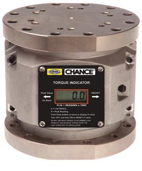
30 TORQUE INDICATORS WIRELESS TORQUE INDICATOR Using the Wireless Chance Torque Indicator, you can install screw anchors to a pre-determined torque value, which gives a positive indication of anchor holding capacity in any soil type. The handheld Wireless Data Logger gives real time information on torque while storing for easy download. The Indicator mounts between the Kelly bar adapter and drive tool (or locking dog assembly). The LCD display is easy to read in full daylight and gives the operator a direct readout of installation torque at all times. Operational temperature range: -30 to 80 C (-22 to 175 F) Accuracy: ±500ft-lb at any reading Torque is measured using strain gauges No shear pins to replace Powered by a standard 9V battery Base unit with wireless display Torque is displayed on Base Unit and on Wireless Display Multiple Wireless Display units can be linked to Base Unit Solid one-piece spool design to withstand bending loads. Top and bottom flange, each provides six holes tapped on a bolt circle and twelve holes tapped on a bolt circle. Data Logger Torque displayed on Data Logger Torque and GPS data recorded and saved on Data Logger Data downloadable from Data Logger to computer spreadsheet C C C C Description Base Indicator with Wireless Display Screen Data Logger Wireless Display Screen Indicator Kit (Base Indicator with Wireless Display Screen and Data logger Installing Tools SHEAR PIN TORQUE LIMITER C for installing torques up to 10,000 ft.-lb. Ordering Information Description 5 1 4" to 7 5 8" Bolt Circle Adapter For installing torques up to 10,000 ft.-lb. This adapter is used to connect two tools having incompatible bolt circles: One with a 5 1 4" bolt circle and one with a 7 5 8" bolt circle. Description T C Shear Pin Torque Limiter 54 *C *T Carton of Shear Pins (Approx pins) Box of Shear Pins (Approx. 510 pins) *Each Shear Pin provides 500 ft.-lb. of torque Advantages: Protection for anchors and installing tools by disconnecting the power when the installing torque reaches a preselected level. Usable in very rocky soil. Durable does not require special storage or handling. Bolt circle adapter with one 1 2" x 5 1 4" bolt circle and one 5 8" x 7 5 8" bolt circle Top and bottom each has six holes tapped 1 2" - 13 on a 5 1 4" bolt circle. 18 Page 4B-30


31 KELLY BAR ADAPTERS Selecting the correct Kelly Bar Adapter is key to building a proper Drive String. Follow these two easy steps: X X Remove the auger from the driver and carefully measure the X and Y dimensions of the Kelly Bar. Match the shape of the Kelly Bar and the X and Y dimensions with the Kelly Bar Adapter charts below. The Y dimension on the Kelly Bar Adapter must be equal to or greater than the Y dimension on the intended Kelly Bar. Y KELLY BAR Y Z Bolt Circle Maximum Torque (6) 1 2" Grade 5 bolts on 5 1 4" Bolt Circle 10,000 ft.-lb. (12) 5 8" Grade 2 bolts on 7 5 8" Bolt Circle 20,000 ft.-lb. A Note about Bolt Circles CHANCE anchor installing tools are provided with appropriate bolt circles for the expected service. The torque limitations for the two standard bolt circles are given below. Never exceed the rated torque of any CHANCE installing tool "-Bolt-Circle Kelly Bar Adapters for 10,000 ft.-lb. Maximum Installing Torque Each of these Kelly Bar Adapters has six holes for 1 2" bolts on a 5 1 4" bolt circle and comes with six 1 2" Grade 5 bolts, nuts & lock washers, Bent-Arm Pin with Coil Lock. Kelly Bar Shape Kelly Bar Dimension X Y Z Square 2 1 4" 2 1 4" 3 1 2" Square 2 1 2" 2 1 4" 3 1 2" Hex " A Hex " 6 1 8" HD Hex 2 5 8" 4 1 4" 8 1 8" HD Hex 2 1 2" 4 1 4" 8 1 8" "-Bolt-Circle Kelly Bar Adapters for 20,000 ft.-lb. Maximum Installing Torque Each of these Kelly Bar Adapters has twelve holes for 5/8 bolts on a 7 5 8" bolt circle and comes with twelve 5 8" Grade 2 bolts, nuts & lock washers, Bent-Arm Pin with Coil Lock. Kelly Bar Shape Kelly Bar Dimension X Y Z C Hex 2 1 2" 4 3 8" 8 1 4" 23 C Hex 2 5 8" 4 3 8" 8 1 4" 23 C Hex 3" 3 1 2" 8" 27 C Hex 2 1 2" 2 1 4" 7" 22 C Square 3" 3 1 2" & " 7" 23 Page 4B-31 Installing Tools


32 BENT-ARM PINS To retain Kelly Bar Adapters and drive tools for Bumper Posts and SS Anchors Each CHANCE plated-steel Bent Arm Pin is designed to attach a Kelly bar adapter to a Kelly bar. The pin also is used to secure SS Anchors and Bumper Posts to their drive tools. Bent Arm pins are included with new tools as required. Order replacement pins for existing tools as listed at right. Dimensions Bent Arm Pin and Coil Lock Assembly Size C " x 5 8" C " x 3 4" C " x 3 4" C " x 1 2" SHOWN HERE AS USED WITH A KELLY BAR ADAPTER. C " x 5 8" BENT ARM PIN *COIL LOCK WARNING: The CHANCE Bent Arm Pin and Coil Lock are the only tested and approved means for through-pin attachment of drive tools. Do not use any other means of attachment. Kelly Bar Adapter Bent Arm Pin and Coil Lock Assembly Kelly Bar Adapter Bent Arm Pin and Coil Lock Assembly HD C C C HD C C C C C C A C C C C C C C Installing Tools SS Anchor Series Tool *Each new Kelly Bar Adapter or Anchor Drive Tool listed above includes a bent-arm pin with coil lock. For Coil Lock only, order Part No. P P. Bent Arm Pin and Coil Lock Assembly C C C C C Bumper Post Tool C Bent Arm Pin and Coil Lock Assembly C Page 4B-32


 5 8\" holes 30 *Coupling to a Kelly bar adapter with a 5 1 4\" bolt circle requires use of T3030166 adapter and limits tool s")


33 SS Helical Pier Anchors Drive Tools ANCHOR DRIVE TOOLS These tools include our proprietary Alignment Window that helps reduce chance of finger pinch when anchor is inserted into tool. Alignment Window also makes it faster and easier to line up the anchor and anchor tool. These drive tools require the appropriate Kelly bar adapter, sold separately. Each comes with bolts, nuts and lockwashers. SS Anchor Series Tool Bolt Circle, Holes Approx SS5/SS ", (6) 1 2" holes 7 C * SS ", (12) 5 8" holes 18 C * SS ", (12) 5 8" holes 30 C * SS ", (12) 5 8" holes 30 *Coupling to a Kelly bar adapter with a 5 1 4" bolt circle requires use of T adapter and limits tool s maximum torque rating to 10,000 ft.-lb. These tools slide into locking dog adapter and are retained by spring loaded dogs. Each of these drive tools includes an integral set of locking dogs that attach the drive tool to the anchor. There is no need to use bent arm pin and coil lock to attach these tools to an anchor. These drive tools require the appropriate Kelly bar adapter, sold separately. Each comes with bolts, nuts and lockwashers. RS278 Helical Pile Anchors Drive Tools Each comes with bolts, nuts and lockwashers. Description Bolt Circle, Holes Approx. C * 5 1 4", (6) 1 2" holes 19 *Maximum torque rating10,000 ft.-lb. Unit fits: Approx. C SS5/SS150/RR STANDARD Locking Dog Assembly 8 C Drive Tool Tough One Locking Dog Assembly 11 T SS175 Drive Tool 26 Tough One Locking Dog Assembly C SS200 Drive Tool 23 SS Anchor Series Tool Bolt Circle, Holes Approx. C SS5/SS ", (6) 1 2" holes 10 C SS ", (12) 5 8" holes C C C Each Drive Tool comes with one set of pins, bolts, nuts and lockwashers. Bolt Circle, Holes Approx. C * 7 5 8", (8) 5 8" holes 44 C RS two-pin set only 5 *Drive Tool maximum torque rating13,000 ft.-lb. C C Page 4B-33 Installing Tools


 5 8\" holes 46 C3031620 RS3500 three-pin set only 6 *Drive Tool maximum torque")

 5 8\" holes 90 RS8625 C3031508 7 5 8\", (12) 5 8\" holes 96 *Maximum torque rating")


34 ANCHOR DRIVE TOOLS RS3500 Helical Pier Anchors Drive Tools Each comes with bolts, nuts and lock washers. Bolt Circle, Holes Approx. C * 7 5 8", (6) 5 8" holes 27 *Coupling to a Kelly bar adapter with a 5 1 4" bolt circle requires use of T adapter and limits tool s maximum torque rating to 10,000 ft.-lb. Each Drive Tool comes with one set of pins, bolts, nuts and lockwashers. RS4500 Drive Tool Each comes with bolts, nuts and lockwashers. Bolt Circle, Holes Approx. C * 7 5 8", (12) 5 8" holes 30 *Maximum torque rating 20,000 ft.-lb. Bolt Circle, Holes Approx. C * 7 5 8", (8) 5 8" holes 46 C RS3500 three-pin set only 6 *Drive Tool maximum torque rating13,000 ft.-lb. C C C C RS6625 and RS8625 Drive Tools Model Bolt Circle, Holes Base Plate Drive Tool Approx. RS6625 C ", (12) 5 8" holes 90 RS8625 C ", (12) 5 8" holes 96 *Maximum torque rating 20,000 ft.-lb. Fits on 10"-Square Base Plate Foundations for *20,000 ft.-lb. Maximum Installing Torque This tool weighs approx. 60 lbs. and has 12 holes on a 7 5 / 8" bolt circle, tapped for 5 / 8" bolts furnished with compatible Kelly Bar adapters. C C *Coupling to a Kelly Bar adapter with a 5 1 / 4"bolt circle requires use of T adapter and limits tool s maximum torque rating to 10,000 ft.-lb. C Universal Tools for Base Plate Foundations These tools fit Foundation Anchors with 9 to " bolt circles. C connects direct to a Kelly bar adapter with (6) 1 2" furnished bolts. C includes (12) 5 8" bolts. Installing Tools Bolt Circle, Holes Approx. C * 5 1 4", (6) 1 2" tapped holes 18 C ", (6) 5 8" drilled holes 49 *Maximum torque rating for C : 10,000 ft.-lb. Maximum torque rating for C : 20,000 ft.-lb. Coupling C to a Kelly bar adapter with a 5 1 4" bolt circle requires use of T adapter and limits tool s maximum torque rating to 10,000 ft.-lb. C C Page 4B-34
35 NOTES Page 4B-35
36 NOTES Page 4B-36

37 210 N. Allen St. Centralia, MO (573) NOTICE: For the latest revision of our and Literature, click here or visit our web site: NOTE: Hubbell has a policy of continuous product improvement. We reserve the right to change design and specifications without notice. Copyright 2014 Hubbell Incorporated NEVER COMPROMISE 4B Page 4B-37
CIVIL CONSTRUCTION PRODUCT CATALOG VOL. I
 CIVIL CONSTRUCTION PRODUCT CATALOG VOL. I Table of Contents Section Description A page CHANCE Helical Round Corner Square Shaft Products Introduction to Round and Square Shaft 3 Square Shaft (SS) Product
STABILITY. SECURITY. INTEGRITY.
 MODEL 150 HELICAL ANCHOR SYSTEM PN #MBHAT STABILITY. SECURITY. INTEGRITY. 150 Helical Anchor System About Foundation Supportworks is a network of the most experienced and knowledgeable foundation repair
Helical Pier Frequently Asked Questions
 Helical Pier Basics Q: What is a Helical Pier? A: A helical pier or pile is an extendable deep foundation system with helical bearing plates welded to a central steel shaft. Load is transferred from the
1. ANSI/ASME Standard B , Square and Hex Bolts and Screws, Inch Series
 SECTION 31 66 13 HELICAL PILES AND HELICAL ANCHORS PART 1 - GENERAL 1.1 DESCRIPTION A. This work pertains to furnishing and installing Helical Piles and Bracket Assemblies shown in the Contract in accordance
5/16" Flange nut. Bolt Keeper Plate (8" Sq. SYS.) (3) 1/2" x 3" Hex head connector zinc plated bolt w/ washers and nut. Anchor 3" sq. 7 Ga.
 (3) 1/2 x 3 Hex head connector zinc plated bolt w/ washers and nut. Anchor 3 sq. 7 Ga.") 2 1/2" x 2 1/2" x 10 Ga. 6" 5" 4" Variable Slipbase (8" Sq. SYS.) 5/16 Corner Bolt W/ nut 5/16" Flange nut Stub Insert (8" Sq. SYS.) Bolt Keeper Plate (8" Sq. SYS.) (3) 1/2" x 3" Hex head connector zinc
2 1/2" x 2 1/2" x 10 Ga. 6" 5" 4" Variable Slipbase (8" Sq. SYS.) 5/16 Corner Bolt W/ nut 5/16" Flange nut Stub Insert (8" Sq. SYS.) Bolt Keeper Plate (8" Sq. SYS.) (3) 1/2" x 3" Hex head connector zinc
Stainless Steel Bench Stand
 Installation Manual Stainless Steel Bench Stand Product(s): 29600 29601 51229 2016 by Fairbanks Scales, Inc. Revision 2 02/16 All rights reserved. Amendment Record STAINLESS STEEL BENCH STAND Document
TABLE OF CONTENTS DESCRIPTION. Safety Instructions Assembly Operation... 7
 TABLE OF CONTENTS DESCRIPTION PAGE Warranty... 1 Safety Instructions... 2 Assembly... 3 Operation... 7 #360 Grain Cleaner Drawings... 8 #360 Grain Cleaner Parts List... 10 Utility Auger Option Drawing...
Transmission Line Support Systems
 Antenna Support Bracket for transmission line The Antenna Support Bracket angle mounts directly to a 4-1/2" (114 mm) OD antenna pipe mount or tower leg. This is ideal for supporting transmission line runs
OWNER'S MANUAL TIE ROD, WALL & FLOOR MOUNTED JIBS. Model JIB-HC, JIB-LC, JIB-FM
 Vestil Manufacturing Company 999 N. Wayne Street, P.O. Box 507 Angola, IN 6703 USA Phone (60) 665-7586 Fax (60) 665-339 sales@vestil.com www.vestil.com Revised 09-0 A company dedicated to solving ergonomic
CONTROLS KIT FOR ALL # & # HARLEY DAVIDSON SPORTSTER MODELS
 INSTALLATION INSTRUCTIONS TC BROS. CHOPPERS PART #0-0075 & #0-0076 (No Pegs) FORWARD CONTROLS KIT FOR ALL 00-0 HARLEY DAVIDSON SPORTSTER MODELS If downloading & printing these instructions online, be sure
MATERIAL COMBINATION NUMBER 2: Corrosive environment requiring harder, wear-resistant seating faces and resistance to dezincification.
 Cast Iron Slide Gates Spec Sheet General The contractor shall furnish and install the following cast iron slide gate assemblies as listed on the Gate Schedule and detailed on the manufacturer s drawings.
Midwest Roadside Safety Facility
 B 64" 1626 602'-8 1/16" 183695 548'-0" 167030 1 2 3 4 5 6 7 8 9 10 11 12 14 15 16 17 18 20 21 22 23 24 25 26 27 28 29 30 31 32 33 34 35 36 373839 40 25 IMPACT 1500A 48" 12 27'-5" 8355 [] 3x7 CL A Galvanized
AUXILIARY FRAMING AND ACCESSORIES
 CUSTOM CABINETS & RACKS STRUT AND ACCESSO- RIES JUNCTION KITS ANGLE AND BRACE KITS SPLICE KITS BRACE KITS INSTALLATION KITS WALL ANGLE KITS RUBBER END CAPS SUPPORT INSTALLATION AND SUPPORT KITS STANCHION
TABLE OF CONTENTS DESCRIPTION. Safety Instructions Assembly Operation... 7
 TABLE OF CONTENTS DESCRIPTION PAGE Warranty... 1 Safety Instructions... 2 Assembly... 3 Operation... 7 #360 Grain Cleaner Drawings... 8 #360 Grain Cleaner Parts List... 10 Utility Auger Option Drawing...
Foundation Specifications for 5.6-Meter Modular Earth Station Antennas
 Installation Instructions Bulletin 237029 Foundation Specifications for 5.6-Meter Modular Earth Station Antennas Revision A Introduction This document specifies typical foundation characteristics, designs,
The MUELLER method of making a main to service connection using the MUELLER E-5 Small Drilling Machine. Hand or power. kpa/34.
 MUELLER SMALL DRILLING MACHINES 2.1 Shaded area indicates change Rev. 9-09 MUELLER Co. manufactures several different small drilling machines for drilling holes from 7/16" to 2" in all types of pipe. Machines
B " 787
 175'0" 53339 3H:1V S.B.P. 25" 635 3H:1V Slope 100'0" 30480 Soil Cut 3H:1V Slope 58" 1474 75" 05 1 2 3 4 5 6 7 8 9 10 11 12 13 25 14 15 16 17 18 20 21 22 23 24 25 2270P Impact 243 60 12 Spaces @ 75" [05]
Foundation Specifications for 7.6-Meter Modular Earth Station Antennas
 Installation Instructions Foundation Specifications for 7.6-Meter Modular Earth Station Antennas Bulletin 237186A Revision A Introduction This document specifies typical foundation characteristics, designs,
Click Here To View Item at
 Click Here To View Item at www.gappower.com (Parts Pages Follow) ATTENTION If you need an Owner s/operator s Manual and/or safety signs (decals), then please contact Danuser. Provide your Model Number
Block Foundation. From the 1950s through the 80s. Hydraulically driven. piers provide bearing. for a settling foundation
 RESCUING FIXING A A Block Foundation Hydraulically driven piers provide bearing for a settling foundation From the 1950s through the 80s before poured concrete became the norm many homes in northern New
The MUELLER method of making a main to service connection using the MUELLER E-5 Small Drilling Machine. The main is drilled out under pressure.
 MUELLER SMALL DRILLING MACHINES 2.1 Rev. 9-09 MUELLER Co. manufactures several different small drilling machines for drilling holes from 7/16" to 2" in all types of pipe. Machines are available in hand
ROUND STEEL POLE STRAIGHT
 PROJECT NAME: CATALOG NUMBER: NOTES: FIXTURE SCHEDULE: Page: 1 of 7 ROUND STEEL POLE SPECIFICATIONS: Pole Shaft The pole shaft is fabricated from hot rolled steel tubing of onepiece construction with a
MSR/MSB Mechanical Setting Tool
 Tech Unit No: 0620000004 Revision: B Approved By: Quality Engineer Date: 2014-12-16 MSR/MSB Mechanical Setting Tool FEATURES: Special designed Bow Spring provides positive control and allows one size Mechanical
USER MANUAL MODEL MZ-100 BOLT TENSION CALIBRATOR
 USER MANUAL MODEL MZ-100 BOLT TENSION CALIBRATOR 442 SOUTH GREEN ROAD SOUTH EUCLID, OHIO 44121 USA VOICE: 216-481-4774 FAX: 216-481-2427 www.skidmore-wilhelm.com TABLE OF CONTENTS Introduction... 2 Typical
1369 & 1379 MOUNT KITS
 November 15, 2014 Lit. No. 64573, Rev. 01 1369 & 1379 MOUNT KITS 1369 Ford Bronco, F 150 4X4 1992-96 1379 Ford F 250/350 4X4 1992-97 Ford F 250 2WD (over 8,500 GVWR) 1992-97 Ford F 350 2WD (over 10,000
RBP-1215B-RX DODGE RAM QUAD CAB RX3
 RBP-1215B-RX3 2002-2017 DODGE RAM 15-3500 QUAD CAB RX3 Passenger side RX-3 Side Step Drill Template Passenger side rear Modular Bracket (6) L Support Brackets Driver side rear Modular Bracket Driver side
INDEX PAGE RELEASE SECTION NUMBER DATE
 INSTALLATION INSTRUCTIONS For Wind Zone 1 (other Wind Zones available on request) Version 11/20/2002 INDEX PAGE RELEASE SECTION NUMBER DATE Approval INTRODUCTION 2 2/26/2001 GENERAL INSTALLATION 3 2/26/2001
Underwater Tool Section
 Underwater Tool Section Tools for Underwater Construction, Salvage and Demolition Stanley Hydraulic Tools is a leading worldwide provider of underwater hydraulic tools to professional divers, marine maintenance,
PARTS LIST COMMANDER 20 VAC-TRAC COMMANDER 27 VAC-TRAC FH 541V
 PARTS LIST COMMANDER 20 VAC-TRAC COMMANDER 27 VAC-TRAC FH 541V UPPER ASSEMBLY 101 6190481 THROTTLE CABLE FOR MODELS WITH ADDITIONAL CHOKE CABLE 1 101 6190751 THROTTLE CABLE FOR MODELS WITH OUT ADDITIONAL
Precision Split Parts Manual
 Precision Split Parts Manual Models 9700 7-Ton Log Splitter 9700 -Ton Log Splitter 086000B /09 Printed in USA THE MANUAL Before you operate your unit, carefully and completely read manuals supplied with
H8508 Impact Wrench SERVICE MANUAL. Model (Serial Code FWN) Model (Serial Code FWP)
 Model (Serial Code FWP)") SERVICE MANUAL H8508 Impact Wrench Model 48755 (Serial Code FWN) Model 48760 (Serial Code FWP) Read and understand all of the instructions and safety information in this manual before operating or servicing
SERVICE MANUAL H8508 Impact Wrench Model 48755 (Serial Code FWN) Model 48760 (Serial Code FWP) Read and understand all of the instructions and safety information in this manual before operating or servicing
Form No Assembly & Operating Instructions for: SAFETY PRECAUTIONS
 Form No. 0230 Assembly & Operating Instructions for: 833 20300 83 2220 837 0-0008 078 SHOP PRESS Max. Capacity: 2 Ton These instructions are intended for various shop presses. Some models are shipped assembled
Wrenches. Wrenches. F o r P. r o f e. s s i o. n a l s. .. S i. n c e 1
 F o r P r o f e Klein s line of wrenches are forged from the finest steel and are designed to deliver great strength, and long working life. Regardless of the job type, Klein has a wrench that will help
Agri-Fab OWNERS MANUAL MODEL NO CU. FT. FARM/YARD CART. CAUTION: Read Rules for Safe Operation and Instructions Carefully
 Agri-Fab OWNERS MANUAL MODEL NO. 45-01772 CAUTION: Read Rules for Safe Operation and Instructions Carefully 14 CU. FT. FARM/YARD CART Safety Assembly Operation Maintenance Parts the fastest way to purchase
400A 40113V, 401A 40120V, & 401AL 40120VL ALUMINUM VERTICAL 4000 LB LIFT INCLUDES SCREW LEG ASSEMBLY INSTRUCTIONS
 12/11/07 PAGE 1 OF 12 400A 40113V, 401A 40120V, & 401AL 40120VL ALUMINUM VERTICAL 4000 LB LIFT INCLUDES SCREW LEG ASSEMBLY INSTRUCTIONS Thank you for purchasing our product! *Please read these instructions
FORD MOUNT INSTALLATION INSTRUCTIONS
 WESTERN PRODUCTS, P.O. BOX 245038, MILWAUKEE, WI 53224-9538 Lit. No. 64289 June 1, 2003 FORD MOUNT INSTALLATION INSTRUCTIONS Bronco (4X4 only) F-150 (4X4 only), F-250/350 Super Duty 1980 1991 Model No.
baseplate GMC Adadia & Buick Enclave
 , Rev 5 07/16 baseplate 9518214 GMC Adadia & Pin Height: 18 Centers: 24 5 8 10 6 11 7 2 4 9 3 1 ITEM PART # QTY DESCRIPTION 1 02990 2.3125NC X 1 HEX BOLT GR.5 2 00036 2.3125 LOCKWASHER 3 00007 2.3125NC
Hex Head Bolt Set N - Includes lock nut. Used to connect male and female T connectors. Galvanized. 3/4" x 3-1/2". Standard Grade (f) Part #24279
 Part #24279") a Standard Grade (3/16 ) and Commercial Grade(1/4 ) Tie Down Is designed for use with 1-1/2" thick lumber (minimum width 6"). All hardware is mounted with 3/8" carriage bolts. All male and female dock
a Standard Grade (3/16 ) and Commercial Grade(1/4 ) Tie Down Is designed for use with 1-1/2" thick lumber (minimum width 6"). All hardware is mounted with 3/8" carriage bolts. All male and female dock
OPERATIONS MANUAL. Port-O-Slitter
 Tapco Products Company The World Leader in Specialty Tools for the Professional Port-O-Slitter OPERATIONS MANUAL General instructions, set up, accessories and guide to using your portable precision slitting,
MSR/MSB Mechanical Setting Tool
 Tech Unit No: 0620000004 Revision: C Approved By: Quality Engineer Date: 201-1-9 MSR/MSB Mechanical Setting Tool FEATURES: Special designed Bow Spring provides positive control and allows one size Mechanical
WAL-MART SUPERCENTER # ; Milwaukie, OR: SPECIFICATIONS. Revisions to Specification Fence
 MILWAUKIE OR #3144-00 ADDENDUM #5 NARRATIVE: 11-08-12 WAL-MART SUPERCENTER #3144-00; Milwaukie, OR: SPECIFICATIONS SPECIFICATIONS Revisions to Specification 02822 Fence Spec division 02822 has been revised
LPK1550 Hydraulic Crimping Tool 15-ton
 SERVICE MANUAL LPK1550 Hydraulic Crimping Tool 15-ton Serial Code FYF Read and understand all of the instructions and safety information in this manual before operating or servicing this tool. Register
PART MATERIALS. Section Fencing Materials. Description
 PART 03000 - MATERIALS Section 03010 - Fencing Materials Description 03010.00 Scope - This section consists of the test requirements, specifications and tolerances for barbed wire, woven wire and chain
ShorePort PWC Lift Instructions " x 138" Sandstone ShorePort " x 138" White ShorePort " x 138" Tan ShorePort
 ShorePort PWC Lift Instructions 00-8" x 8" Sandstone ShorePort 009-8" x 8" White ShorePort 090-8" x 8" Tan ShorePort....... - PUT SAFETY FIRST To avoid the risk of personal injury or death, study and fully
Gared Pro-S Portable Backstop
 Models: 9616 & 9618 Installation, Operation and Maintenance Instructions Please read all instructions before attempting installation or operation of these units SAVE THESE INSTRUCTIONS FOR FUTURE USE PUBLICATION
OPERATION, SERVICE AND PARTS INSTRUCTION MANUAL 1813 BENDING TABLE FOR 881 HYDRAULIC BENDER
 OPERATION, SERVICE AND PARTS INSTRUCTION MANUAL 1813 BENDING TABLE FOR 881 HYDRAULIC BENDER Read and understand this material before operating or servicing this bender. Failure to understand how to safely
MM750 Installation Instructions
 MM750 Installation Instructions IMPORTANT SAFETY INSTRUCTIONS - SAVE THESE INSTRUCTIONS Please read this entire manual before you begin. Do not unpack any contents until you verify all requirements on
installation guide 1 GUIDE#: pwb-wwtowv1-pol-003
 g300 WAKEBOARD tower installation guide INSTALLATION SUPPORT 1 important information This WakeWorks wakeboard tower fits motor boats with 76-108 inch wide beam widths. This measurement is taken from the
HYDRAULIC MOWER AHRM4H, HRM48H Parts Catalog INDEX HOME TRACTOR ATTACHMENTS APPLICATION CHART
 R Ingersoll HYDRAULIC MOWER AHRM4H, HRM48H Parts Catalog 8-3091 HOME TRACTORS ATTACHMENTS PAINT GENERAL INFO INDEX Deck. Belt and Idler Pulley...5 Mounting Bracket...7 Rear Wheels...7 Hydraulic Drive...9-13
Technologies, Inc. Installation Instructions for Anchors & Components. Rev PAGE 1 / 11
 Installation Instructions for Anchors & Components PAGE 1 / 11 GROUND ANCHOR INSTALLATION INSTRUCTIONS NOTE: 1) The tensioning bolt can be inserted in the head from either side. 2) In areas of severe cold
MM540 Installation Instructions IMPORTANT SAFETY INSTRUCTIONS - SAVE THESE INSTRUCTIONS
 MM50 Installation Instructions IMPORTANT SAFETY INSTRUCTIONS - SAVE THESE INSTRUCTIONS Please read this entire manual before you begin. Do not unpack any contents until you verify all requirements on PAGE.
Swivel Hoist Ring RIGGING ACCESSORIES. Color coded to distinguish between UNC (Red) and Metric (Silver) thread types.
 and Metric (Silver) thread types.") RIGGING ACCESSORIES Color coded to distinguish between UNC (Red) and Metric (Silver) thread types. Available in UNC and Metric thread sizes. UNC threads available in sizes from 800 pounds to 100,000 pounds,
RIGGING ACCESSORIES Color coded to distinguish between UNC (Red) and Metric (Silver) thread types. Available in UNC and Metric thread sizes. UNC threads available in sizes from 800 pounds to 100,000 pounds,
Star Trac Turbo Trainer Assembly & Setup
 Star Trac Turbo Trainer Use the following procedures to unpack and assemble your Turbo Trainer manufactured by Star Trac. UNPACKING AND PARTS LIST Position the shipping carton so the Heavy End logo is
B32157 UNDERCARRIAGE KIT. Jeep Cherokee Jeep Wagoneer Jeep Comanche Parts List and Installation Instructions CAUTION
 October 15, 2007 Lit. No. B64110, Rev. 01 B32157 UNDERCARRIAGE KIT Jeep Cherokee 1984-01 Jeep Wagoneer 1984-93 Jeep Comanche 1986-92 Parts List and Installation Instructions Read this document before installing
One Piece LSD/Vector Pads from TIE DOWN ENGINEERING Easier installation with 70% fewer parts Lower cost with competitive pricing
 NEW! One Piece SD/ector Pads from TIE DOWN ENGINEERING Easier installation with 70% fewer parts ower cost with competitive pricing Do the Math! Compare material and labor cost with the New SD and ector
Available in high-capacity. and assembled by hand for smooth operation. Durable chrome-plated finish. Heat-treated for long life.
 Klein s line of wrenches are forged from the finest steel and are designed to deliver great strength and long working life. Regardless of the job type, Klein has a wrench that will help the professional
FASTENERS, MEASUREMENTS AND CONVERSIONS
 FASTENERS, MEASUREMENTS AND CONVERSIONS Bolts, Nuts and Other Threaded Retainers Although there are a great variety of fasteners found in the modern car or truck, the most commonly used retainer is the
Heartland Perma-Column 1841 E 1450 Rd. Lawrence, KS (785)
") 141 E 1450 Rd. Lawrence, KS 66044 (75) 594-5696 Perma-Column Installation Instructions i Unlike any other concrete post-frame foundation system, Perma-Column Precast Concrete Piers use 10,000 psi concrete
141 E 1450 Rd. Lawrence, KS 66044 (75) 594-5696 Perma-Column Installation Instructions i Unlike any other concrete post-frame foundation system, Perma-Column Precast Concrete Piers use 10,000 psi concrete
MAST ARMS & POLES. Ornamental Pole Top & Bases
 Ornamental Pole Top & Bases Pelco s decorative pole top and bases make the traffic signal aesthetically pleasing to the eye. In addition to the standar 4-piece, Pelco also manufactures the bases with an
WARNING. BX Ford Explorer With Adaptive Cruise Control & Eco Boost Installation Instructions
 Please read BOTH these and the General Instructions before attempting to install or operate this equipment. 1. Blue Ox towing products and accessories are intended to be installed by Blue Ox Dealers who
Water Rocket Launcher
 Rocket Activity Water Rocket Launcher Objective Construct a launch platform for launching water rockets. National Science Content Standards Physical Science Position and motion of objects Motions and forces
767, 777, DC-10, L-1011, MD-11 Tow Bar Equipment Manual
 514 MECKLEM LANE, ELLWOOD CITY, PENNSYLVANIA 16117 www.hallindustries.com E-mail: service@hallindustries.com 767, 777, DC-10, L-1011, MD-11 Tow Bar Equipment Manual Use This Manual for 1. Operating Procedures
M-6 CORE BORE DRILLING MACHINE PARTS LIST. September 18, Part #
 M-6 CORE BORE DRILLING MACHINE PARTS LIST September 8, 0 Part # 8008 Proposition 6 State of California Warning! Engine exhaust and some its constituents are known to the State of California to cause cancer,
Wheeler Rex Ashtabula, Ohio Tel: Fax:
 Wheeler Rex Ashtabula, Ohio Tel: 800 321 7950 Fax: 440 992 2925 wheeler@wheelerrex.com www.wheelerrex.com December 2012 There are three different types of shell cutters. Nominal Hole Size Part No. 4" 3395
Blizzard, PO Box , Milwaukee, WI UNDERCARRIAGE KIT
 Blizzard, PO Box 245038, Milwaukee, WI 53224-9538 www.blizzardplows.com December 1, 2013 Lit. No. 95041, Rev. 01 33887-1 UNDERCARRIAGE KIT Dodge Ram 2500/3500 Gasoline 2010 - Dodge Ram 2500/3500 Diesel
installation guide 1 GUIDE#: pwb-assault-001
 assault WAKEBOARD tower installation guide INSTALLATION SUPPORT 1 important information This Aerial wakeboard tower fits motor boats with 76-108 inch wide beam widths. This measurement is taken from the
Assembly Instructions
 page 1 Serious personal-injury to the operator or bystanders, as well as damage to equipment or property, can occur, if all safety and assembly instructions, provided with this product, are not followed.
Rodney Hunt. A GA Industries Company Glydaseal Gates
 Rodney Hunt A GA Industries Company Glydaseal Gates GUIDE BRONZE GUIDE BAR FRAME NUT POCKET SEAT FACING RESILIENT INVERT SEAT DISC GUIDE BAR ADJUSTMENT BOLT WITH LOCK NUT GUIDE BAR ATTACHING BOLT The Glydaseal
TK 1014 A POWER SHEAR
 TIN KNOCKER TK 1014 A POWER SHEAR Parts Diagram & Operating Instructions TAAG INDUSTRIES CORP. 1550 SIMPSON WAY, ESCONDIDO, CA 92029 Tel: (800) 640-0746 Fax: (760) 727-9948 Website: www.tinknocker.com
SECTION 9: PARTS Main
 SECTION 9: PARTS Main 58 63 67 66 65 67 66 59 58 49 58 48 49 61A 61 64 62 55 50 35-3 34 35-1 57 56 41 42 151 51 50 33A 35-2 30A 30A-1 35 38 39 31 32 18 40 43 44 68 51 41 45 46 57 56 55 47 152 153 20 21
DIAMOND MODEL CC1900 EARLY ENTRY CONCRETE SAW PARTS LIST P R O D U C T S. (March 2012) Part #
 Part #") DIAMOND P R O D U C T S EARLY ENTRY CONCRETE SAW PARTS LIST MODEL CC1900 (March 2012) Part #1801617 (Intentionally Blank) TABLE OF CONTENTS Description Page No. Frame Assembly....4-5 Engine Assembly......6
DIAMOND P R O D U C T S EARLY ENTRY CONCRETE SAW PARTS LIST MODEL CC1900 (March 2012) Part #1801617 (Intentionally Blank) TABLE OF CONTENTS Description Page No. Frame Assembly....4-5 Engine Assembly......6
The DeltaGrip System. Safety and Operating Instructions. Trigger. Air Supply Connection. Handle Assembly. Air Line Assembly.
 The DeltaGrip System Safety and Operating Instructions Trigger Air Supply Connection Handle Assembly Air Line Assembly Punch Die Pneumatic Diaphragm Assembly Shackle, Pin & Jam Nut Jaw Frame Shoulder Screw
INSTALLATION INSTRUCTIONS
 INSTALLATION INSTRUCTIONS R5 STEP BOARD APPLICATION: 2009-2017 Dodge Ram 1500 Quad / Crew Cab 2010-2017 Dodge Ram 2500/3500 Crew Cab PART NUMBER: 28-51040, 28-51045, 28-51050, 28-51055 ITEM QUANTITY DESCRIPTION
Please read BOTH these Installation Instructions and the General Instructions prior to installing or operating this equipment.
 Attachment Tab Height: 24-3/4 Attachment Tab Width: 21 Serial Number Please read BOTH these and the General Instructions prior to installing or operating this equipment. 1. Blue Ox towing products and
Power Train Lift Max. Capacity: 1,250 lbs.
 655 EISENHOWER DRIVE OWATONNA, MN 55060 USA PHONE: (507) 455-7000 TECH. SERV.: (800) 533-6127 FAX: (800) 955-8329 ORDER ENTRY: (800) 533-6127 FAX: (800) 283-8665 INTERNATIONAL SALES: (507) 455-7223 FAX:
FORD MOUNT INSTALLATION INSTRUCTIONS
 WESTERN PRODUCTS, P.O. BOX 245038, MILWAUKEE, WI 53224-9538 Lit. No. 67449 FORD MOUNT INSTALLATION INSTRUCTIONS Bronco, F-150/250/350 4X4 1992-1996 and Ford F-250 2WD (over 8,500 GVWR) Ford F-350 2WD (over
Please read BOTH these Installation Instructions and the General Instructions prior to installing or operating this equipment.
 Attachment Tab Height: 16-1/2 Serial Number Attachment Tab Width: 24 Please read BOTH these and the General Instructions prior to installing or operating this equipment. 1. Blue Ox towing products and
WARNING BX Dodge Ram 1500 (2/4WD, Include Sport, No Mega Cab) 2008 Dodge Ram 1500 Quad St/Slt Installation Instructions.
 2008 Dodge Ram 1500 Quad St/Slt Installation Instructions.") Please read BOTH these and the General Instructions before attempting to install or operate this equipment. 1. Blue Ox towing products and accessories are intended to be installed by Blue Ox Dealers who
Please read BOTH these and the General Instructions before attempting to install or operate this equipment. 1. Blue Ox towing products and accessories are intended to be installed by Blue Ox Dealers who
M-5 PRO CORE BORE PARTS LIST DRILLING MACHINE. (March 2017) Part #
 Part #") M- PRO CORE BORE DRILLING MACHINE PARTS LIST (March 07) Part #809 Table of Contents Description Page No. Carriage Assembly....... - Combo Base Assembly....... - 7 Anchor Base Assembly........8 Anchor
M- PRO CORE BORE DRILLING MACHINE PARTS LIST (March 07) Part #809 Table of Contents Description Page No. Carriage Assembly....... - Combo Base Assembly....... - 7 Anchor Base Assembly........8 Anchor
VIEWING OPTIONS: In Adobe PDF Viewer, from the main toolbar choose View, then Page Display, turn on Two-Up and Show Cover Page During Two-Up
 VIEWING OPTIONS: To make our catalog easier to read we recommend using a two page display, as some sections have one page for the exploded view and one for the parts listing. Changing these settings will
WARNING Honda CR-V Honda Element Installation Instructions BX2232. Serial Number
 Please read BOTH these and the General Instructions before attempting to install or operate this equipment. 1. Blue Ox towing products and accessories are intended to be installed by Blue Ox Dealers who
HR24TS Rotary Rake. Serial Numbers less than Illustrated Parts Breakdown. Curtain & Guards, Front
 HRTS Rotary Rake Serial Numbers less than 00 Illustrated Parts Breakdown Page Page Page Page Page Page Page Page Page Page Page Page Tongue Front Frame Front Axle Curtain & Guards, Front Front Pivot Bridge
Precision Split Parts Manual
 Precision Split Parts Manual Model 917001 7-Ton Log Splitter 0860400 /09 Printed in USA THE MANUAL Before you operate your unit, carefully and completely read manuals supplied with the unit. The contents
INSTALLATION INSTRUCTIONS, AND PARTS LIST
 INSTALLATION INSTRUCTIONS, AND PARTS LIST LB20 SERIES RAMPS Link Mfg. Ltd. 223 15th St. N.E. Sioux Center, IA USA 51250-2120 (712) 722-4868 Fax (712) 722-4779 QUESTIONS? CALL CUSTOMER SERVICE 1-800-248-3057
1-CYLINDER TORNADO LIFT INSTALLATION MANUAL
 1-CYLINDER TORNADO LIFT INSTALLATION MANUAL Model: TORNADO LIFT 2K 2018 Edition PROVIDED FOR ASSEMBLY Foot Pads 12 sq. Square Tube Legs (optional) Cross Beams Side Beams 2.5 Dia. Cylinders (with hoses
RTI TECHNOLOGIES, INC.
 RTI TECHNOLOGIES, INC. BRC500 & BRC550 Arbor/Spindle Mechanism Adjustment & Service Technical Instructions The arbor/spindle mechanism of the BRC500/550 is designed to be robust for long life. Occasionally
MODEL NO OWNER S MANUAL ASSEMBLY & OPERATING INSTRUCTIONS
 COMPACT POST HOLE DIGGER MODEL NO. 24045000 OWNER S MANUAL ASSEMBLY & OPERATING INSTRUCTIONS THIS SAFETY ALERT SYMBOL IDENTIFIES IMPORTANT SAFETY MESSAGES IN THIS MANUAL. FAILURE TO FOLLOW THIS IMPORTANT
MODEL NO (S ) POST HOLE DIGGER OWNER S MANUAL
 POST HOLE DIGGER OWNER S MANUAL") MODEL NO. 2100220 (S24045500) POST HOLE DIGGER OWNER S MANUAL ASSEMBLY & OPERATING INSTRUCTIONS THIS SAFETY ALERT SYMBOL IDENTIFIES IMPORTANT SAFETY MESSAGES IN THIS MANUAL. FAILURE TO FOLLOW THIS IMPORTANT
MODEL NO. 2100220 (S24045500) POST HOLE DIGGER OWNER S MANUAL ASSEMBLY & OPERATING INSTRUCTIONS THIS SAFETY ALERT SYMBOL IDENTIFIES IMPORTANT SAFETY MESSAGES IN THIS MANUAL. FAILURE TO FOLLOW THIS IMPORTANT
Installation Instructions Kit, Base Rail Bracket Part # 31413
 Installation Instructions Kit, Base Rail Bracket Part # 31413 Dealer / Installer: End User: Provide a copy of these Instructions to the end user of this product. These Instructions provide important operating
KOLO SHELTER Installation Instructions Parts List
 Parts List Roof Cap Rafter Upright Polycarbonate Polycarbonate Drop Polycarbonate Flange Center Weldment (Short length shown above) Polycarbonate Edge Bolt.25 x 6.5 Bolt.625 x 7.5 Threaded Rod.75 x 14
Blizzard, PO Box , Milwaukee, WI UNDERCARRIAGE KIT. Dodge Ram 2500/3500. Installation Instructions CAUTION
 Blizzard, PO Box 245038, Milwaukee, WI 53224-9538 www.blizzardplows.com November 1, 2011 Lit. No. 41415, Rev. 01 33885 UNDERCARRIAGE KIT Dodge Ram 2500/3500 2010 - Installation Instructions Read this document
Lumber Smith. Assembly Manual. If you are having problems assembling the saw and need assistance, please contact us at:
 Lumber Smith Assembly Manual If you are having problems assembling the saw and need assistance, please contact us at: 804-577-7398 info@lumbersmith.com 1 Step 1 Safety Carefully read the Owners Manual.
CAT-350 Product Manual
 CAT-350 Product Manual Release 01/17 www.ingalcivil.co.nz CAT-350 NZ Assembly Manual Ingal Civil Products NZ 40 Tironui Road, Auckland 2112 www.ingalcivil.co.nz Important: These instructions are for standard
CertainTeed INSTALLATION GUIDE SIMTEK FENCE PRODUCTS. Fence Installation Guide 3', 4' & 6' High
 CertainTeed INSTALLATION GUIDE SIMTEK FENCE PRODUCTS Fence Installation Guide 3', 4' & 6' High INSTALLATION GUIDE These instructions are designed to assist both professional installers and do-it-yourselfers
Operating Instructions and Parts Manual. 10 x 16 Horizontal Band Saw Models J-7020, J-7040
 Operating Instructions and Parts Manual 10 x 16 Horizontal Band Saw Models J-7020, J-7040 JET 427 New Sanford Road LaVergne, Tennessee 37086 Part No. M-414472 Ph.: 800-274-6848 Revision C2 03/2014 www.jettools.com
Installation. Loader Arm Wear Strip Kit TX 1000 Compact Tool Carrier WARNING. Loose Parts. Installation Instructions
 Loader Arm Wear Strip Kit TX 1000 Compact Tool Carrier Model No. 133-0241 Form No. 3406-164 Rev B Installation Instructions WARNING CALIFORNIA Proposition 65 Warning This product contains a chemical or
Assmann Corporation of America TANK INSTALLATION AND USE GUIDELINES FOR BULK STORAGE TANKS
 Assmann Corporation of America TANK INSTALLATION AND USE GUIDELINES FOR BULK STORAGE TANKS General Information Assmann polyethylene storage tanks are manufactured to give you the toughest, most reliable
MOUNT KIT. Dodge Ram 2500/3500 (All) Dodge Ram 2500/3500 (Gasoline only) Installation Instructions CAUTION
 Dodge Ram 2500/3500 (Gasoline only) Installation Instructions CAUTION") November 15, 2014 Lit. No. 41376, Rev. 05 33884 MOUNT KIT Dodge Ram 2500/3500 (All) 2010-12 Dodge Ram 2500/3500 (Gasoline only) 2013 - Installation Instructions Read this document before installing the
November 15, 2014 Lit. No. 41376, Rev. 05 33884 MOUNT KIT Dodge Ram 2500/3500 (All) 2010-12 Dodge Ram 2500/3500 (Gasoline only) 2013 - Installation Instructions Read this document before installing the
Oxford Stalls Installation Instructions
 Oxford Stalls Installation Instructions RAMM Horse Fencing and Stalls 13150 Airport Hwy. Swanton, OH 43558-9615 1-800-434-8456 Rev. 8/15/17 Before You Start Typical stall sizes are 10 x 10, 12 x 12 or
IN-BED FRAME MOUNT INSTALLATION INSTRUCTIONS
 Lit. No. 13666, Rev. 05 December 5, 2005 IN-BED FRAME MOUNT INSTALLATION INSTRUCTIONS FOR SINGLE-STAGE AND TWO-STAGE TAILGATE SPREADERS Read Owner's Manual before operating or servicing spreader. Empty