Kee Pallet Gate Operation and Maintenance Manual
|
|
|
- Suzan Lloyd
- 6 years ago
- Views:
Transcription


1 R E L I B L E S F E C C E S S Kee Pallet Gate Operation and Maintenance Manual
2 2

.")


3 Kee Pallet Gate System Overview PLLET SFETY GTES KEE PLLET GTES are a range of pallet/mezzanine gates designed specifically to provide permanent hazard protection when moving goods between different working levels. KEE PLLET GTES can provide permanent protection for any openings where material/pallet access is required. The gates have been specifically designed to provide a retro-fit solution to existing guardrails where opening protection is required. PPLICTION The KEE PLLET GTE range has been designed to be fully adjustable in width and can accommodate openings up to 1.8m (6 ). Connecting the KEE PLLET GTE to the supporting structure is simple using KEE KLMP fittings which are directly fixed to the existing guardrail or mechanically/chemical fixed to the masonry or concrete structure DURBILITY KEE PLLET GTES are available in a range of high quality finishes. Galvanised: components are supplied with a galvanised finish to BS EN ISO 1461 and STM 53: Hot Dip Galvanised Coatings Specification and Testing Methods, giving an average coating of between microns. COMPONENT BSED SYSTEMS ll products consist of high quality tubing and cast clamps that seamlessly compliment the Company s safety portfolio. KEE PLLET GTE is easily installed to existing and new structures using all variants of the KEE KLMP range to provide a safe compliant solution. 3


4 Kee Pallet Gate System Overview TESTING & CERTIFICTION Tested in accordance with the following (See Specification Section for full details) :- EN ISO Part 3 & Part 4 OSH NSI Ontario Building Code, NBC and British Columbia Building Code Canadian Standards ssociation Canada Occupational Health and Safety LIFE CYCLE TESTING - BS :2009 Clause Opening and closing of the hinge mechanism. SLT SPRY TESTING - STM B over 200 hours to assess performance of coating to resist corrosion. OFFICIL DOCUMENTTION ll Systems comply with the following:- Work at Height Regulations. European Union Directives together with requirements of CDM Regulations. US & Canada. ESTHETICS The smooth lines of the standard galvanised finish can be further enhanced by the application of powder coating to EN US-M SYSTEMS DISTRIBUTORS KEE PLLET GTE is available as a supply and installation service or component supply only. Products are available from one of Kee Safety s licensed distributors. 4
5 Kee Pallet Gate Compliance PRODUCT SPECIFICTION EUROPEN US - CNDIN FETURES:- Manually operated balanced safety pallet gate. GENERL KEE PLLET GTE requires physical fixing to the buildings structure. MTERILS EUROPEN Steel tubing to EN mm diameter tube x 3.2mm wall thickness. 48.3mm diameter tube x 3.2mm wall thickness ll steel components galvanised to BS EN ISO ll fixings are hot dipped galvanised to BS EN ISO ll cast clamps have THREDKOT applied to all tapped holes. ll grub screws are carbon steel and have KEE KOT protection applied to ensure minimal maintenance. Where tubing is cut on site zinc rich paint is applied to the cut end of the tube. Powder Coating to EN US & CND ll steel components galvanised steel to STM 53. ll fixings are hot dipped galvanised to STM 53. Powder Coating to US-M LYOUT EUROPE & CND Recommended installed height of a KEE PLLET GTE is 1.1m in Europe and Canada depending on the structure it is fixed to and National Regulations. Standard pallet gate width 1.4m. Internal gap between top and bottom guardrail 466mm. Guardrail centre to centre 500mm TESTING EN ISO Part 3 & Part 4 OSH 200 lb applied to the top rail of the gate and 150 lb on the mid-rail of the gate NSI The gate must comply with the same loading requirements as the structure to which it is attached. IBC designed to resist linear load of 50 lb/ft Ontario Building Code, NBC and British Columbia Building Code Handrails and any building element that could be used as handrail shall be designed and attached in such a manner to resist, (a) a concentrated load at any point of not less than 0.9 kn (202 lb) and a uniformly distributed load of 0.7 kn/m (48 lb/ft). OBC and NBC state all other guards 0.75 kn/m (52 lb/ft) or concentrated load of 1.0 kn (224 lb) applied at any point on top of the guard Evenly distributed vertical load on top of the guard 1.5 kn/m (103 lb/ft) Canadian Standards ssociation 0.9 kn (202 lb), 0.7 kn/m (48 lb/ft) states Guard a protective barrier around an opening in a floor or at the open side of stairs, a landing, balcony, mezzanine, gallery, raised walkway or other location; used to prevent accidental falls from one level to another; such a barrier may or may not have openings through it. Canada Occupational Health and Safety 890N applied along top rail (200 lb) LIFE CYCLE TESTING - BS :2009 Clause Opening and closing of the hinge mechanism. SLT SPRY TESTING - STM B over 200 hours to assess performance of coating to resist corrosion. LYOUT US Recommended installed height of KEE PLLET GTE is 42 in the US depending on the structure it is fixed to and National Regulations. Standard Type, B and C gate width is 1.6m, Type D gate features 1.8m opening. Internal gap between top and bottom guardrails is


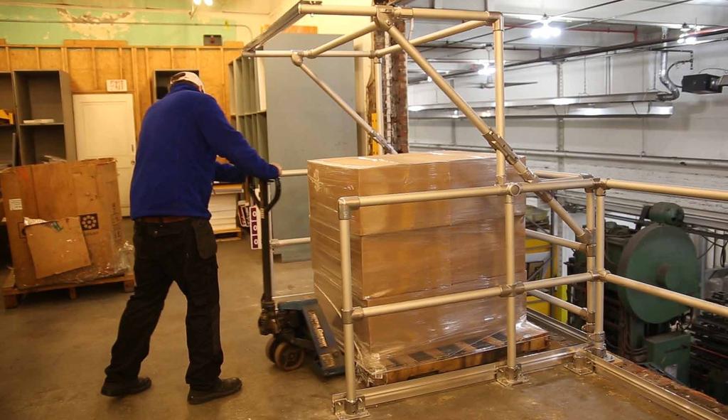
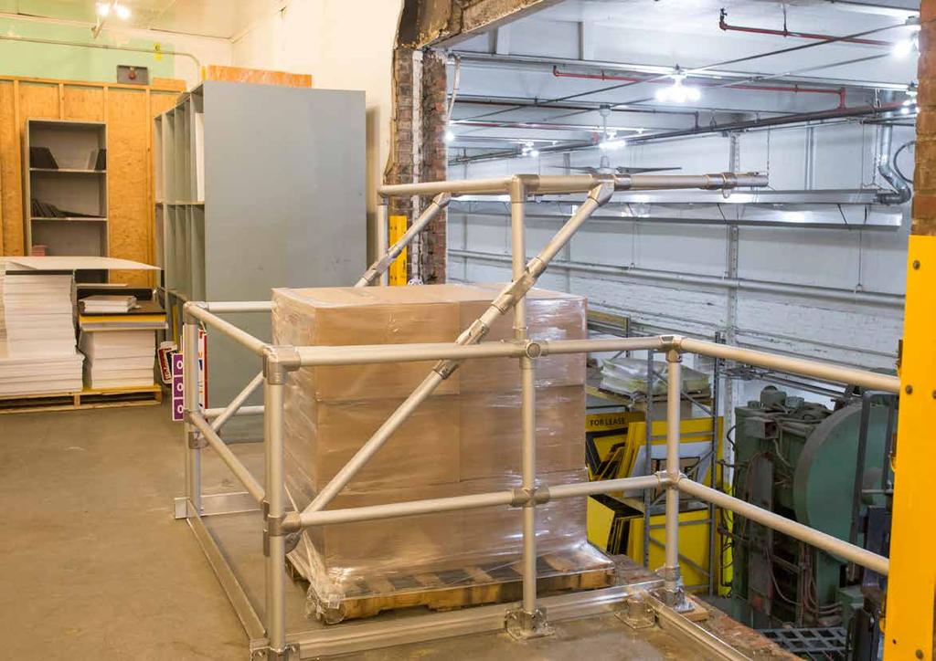
6 Kee Pallet Gate Models TYPE STNDRD PLLET GTE - SGPGTYGV Type gate is balanced for a positive open and close action. This gate accepts pallets up to 1.4m x 1.48m with a maximum height capacity of 1.6m. Toe-board mounted on mezzanine edge side to protect workers below. Manufactured from steel to EN dia. x 3.2mm wall thickness tube and 33.7 dia. x 3.2mm wall thickness tube to meet requirements of EN Net Weight 95kg. TYPE B NRROW PLLET GTE - SGPGTYBGV The Type B narrow frame pallet gate is perfect for use on mezzanines where space is limited. The design of this gate means less floorspace is required to load and unload. Balanced for a positive open and close action. This gate accepts pallets up to 1.4m x 1.48m with a maximum height capacity of 1.8m. Manufactured from steel to EN of 48.3 dia. x 3.2mm wall thickness tube and 33.7 dia. x 3.2mm wall thickness to meet requirements of EN Toe-board mounted on mezzanine edge side. Net Weight 95kg. TYPE C TLL PLLET GTE - SGPGTYCGV The Type C gate offers the tallest capacity of the Kee Pallet Gates. The cantilever design of this gate provides maximum height with minimal ceiling height requirement. Balanced for a positive open and close action. This gate accepts pallets up to 1.4m x 1.48m with a maximum height capacity of 2.2m. Manufactured from steel to EN dia. x 3.2mm wall thickness tube and 33.7 dia. x 3.2mm wall thickness tube to meet requirements of EN Toe-board mounted on mezzanine edge side. Net Weight 105kg. 6 TYPE D PREMIUM WIDE PLLET GTE - SGPGTYDL The Type D gate offers the widest load capacity of the Kee Pallet Gates. The design of this gate provides maximum load width, whilst also offering 2m head clearance for workers. Made from luminium and balanced for a positive open and close action. This gate accepts pallets up to 1.4m x 1.95m with a maximum height capacity of 1.6m. Manufactured from Grade 6082 T6 luminum 48.3mm dia. x 4mm wall thickness tube to meet requirements of EN Toe-board mounted on all sides to protect gates from pallet contact. Net Weight 75kg.

7 Colour coded diagram of components Carefully take all the components out of the packaging and ensure all components listed on the next page have arrived. Components for a Type gate 7
8 Components for a Type gate G B x1 C x4 F x4 D E x1 Fixing items 4no. M10 x 50mm Bolts 4no. M10 Plain nuts 4no. M10 Plain washers 12no. Plastic end caps ll measurements are shown in mm

9 Building and mounting Type gate TOOLS REQUIRED You will need the following in order to install the Kee Pallet Gate: Marker Pen Tape Measure 2No. 30mm Ring Spanners 1No. 17mm Ring Spanner 1/4 Hex Key/Socket 5/16 Hex Key/Socket Torque Wrench Nm approx Small Magnetic Level Floor fixings to suit surface D F 1. Using the above guide mark the position of the holes. Carefully drill a 12mm hole on each mark. Remove any debris using suitable extraction equipment. 2. Build 2No frames using 2No. (F) uprights, 1No. (D) horizontal per frame. Once tubes are fully inserted tighten grub screws using 5/16 hex key. 3. lign each frame to the pre-drilled holes. Slight adjustment of the fittings may be necessary to centre correctly with the holes. 4. Using the 4No (62-8) castings at the base of the frame legs mount all 4No. feet to the floor. Ensure fixings are torqued as per suppliers guidelines. 5. Take part () with hinge arm and mount wide size 8 (48.3mm dia) tube to frame with gate rail on inner side. Repeat this step for other frame. NB. Slight loosening of the frame may be required to allow the horizontal to be inserted into the frame. 9
 horizontal tubes on mezzanine edge end and add part (G) upright tubes as above onto parts (C)")
 horizontal tubes to upper and lower cantilever tubes.")
 part to the (G) uprights by sliding 4No.")


10 Building and mounting Type gate G c c G B G E 6. Rotate cantilever part () so this is as above. dd 2no. part (C) horizontal tubes on mezzanine edge end and add part (G) upright tubes as above onto parts (C) during the process. Tighten using 1/4 hex key. 7. On opposite end to mezzanine edge add 2no. part (C) horizontal tubes to upper and lower cantilever tubes. Then add part (B) onto ends of lower cantilever tubes. Tighten using 1/4 hex key. 8. Mount toe-board (E) part to the (G) uprights by sliding 4No. bolt heads into the track along the back of the toe-board. Carefully align 2No. bolts so they fit through each of the M51-6 fitting. dd the washer and nut and loosely tighten to permit movement within the toe-board for adjustment in next step. 9. Check toe-board is central within the frame and tighten nuts to 15Nm to ensure it is held securely in place. 10. Ensure all fittings are correctly torqued to 39Nm and all tubes are level. Ensure gate operates smoothly and opens and closes positively Place plastic end caps on all exposed tube ends. These may need to be tapped into place using a rubber mallet. Note:- Installing Kee Pallet Gate Ensure gate fittings are correctly torqued. Establish that the gate will close correctly. Failure to do so could result in death or serious injury.
11 Colour coded diagram of components Carefully take all the components out of the packaging and ensure all components listed on the next page have arrived. Components for a Type B Gate 11
12 Components for a Type B Gate F G H B C x1 I D x1 E x4 dditional items 4no. M10 x 50mm Bolts 4no. M10 Plain nuts 4no. M10 Plain washers 12no. Plastic end caps ll measurements are shown in mm

13 Mounting and building Type B gate TOOLS REQUIRED You will need the following in order to install the Kee Pallet Gate: Marker Pen Tape Measure 2No. 30mm Ring Spanners 1No. 17mm Ring Spanner 1/4 Hex Key/Socket 5/16 Hex Key/Socket Torque Wrench Nm approx Small Magnetic Level Floor fixings to suit surface I B H Establish that the gate will close correctly!! Failure to do so could result in Death or serious injury. 1. Using the above guide mark the position of the holes. Carefully drill a 12mm hole on each mark. Remove any debris using suitable extraction equipment. 2. Build 2No frames using 1No. (H) upright, 1No. (I) upright and 2No. (B) horizontal parts per frame. Once tubes are fully inserted tighten grub screws using 5/16 hex key. 3. lign each frame to the pre-drilled holes. Slight adjustment of the fittings may be necessary to centre correctly with the holes. 4. Using the 4No (62-8) castings at the base of the frame legs mount all 4No. feet to the floor. Ensure fixings are torqued as per suppliers guidelines. 5. Take part () with bearing attached and with gate rail on inner side mount to the vertical tube of the frame. Ensure bearing is facing mezzanine edge side as per diagram above. Repeat this step for other frame. 13
 horzontal tubes through the cantilever tube ends. During this process add 2no.")
 horizontal through cantilever tube ends. dd 2no. (F) uprights onto ends of horizontal tubes.")
14 Mounting and building Type B gate G E G G 6. Ensure frame is parallel. If not, the gate will not operate smoothly. djust this if necessary by rotating the fittings. Note location of hinge mechanism as mentioned in previous step. 7. On Mezzanine leading edge slide 2no. part (E) horzontal tubes through the cantilever tube ends. During this process add 2no. part (G) vertical uprights with toe-board brackets onto horizontal tubes part (E). 8. Slide part (G) vertical uprights to the left and right hand side of horizontals as shown above. Tighten using 1/4 hex key. E F G D 9. On opposite end to mezzanine edge slide 2no. part (E) horizontal through cantilever tube ends. dd 2no. (F) uprights onto ends of horizontal tubes. Tighten using 1/4 hex key. 10. Mount toe-board (D) part to the I uprights by sliding 4No. bolt heads into the track along the back of the toe-board. Carefully align 2No bolts so they fit through each of the M51-6 fitting. dd the washer and nut and loosely tighten to permit movement within the toe-board for adjustment in next step. 11. Check toe-board is central within the frame and tighten nuts to 15Nm to ensure it is held securely in place. 14
15 Mounting and building Type B gate C 12. On opposite end to mezzanine edge insert part (C) horizontal tube by sliding tube 100mm up the vertical posts. Tighten using 1/4 hex key. 13. Ensure all fittings are correctly torqued to 39Nm and all tubes are level. Ensure gate operates smoothly and opens and closes positively. 14. Place plastic end caps on all exposed tube ends. These may need to be tapped into place using a rubber mallet. 15 Note:- Installing Kee Pallet Gate Ensure gate fittings are correctly torqued. Establish that the gate will close correctly. Failure to do so could result in death or serious injury.

16 Colour coded diagram of components Carefully take all the components out of the packaging and ensure all components listed on the next page have arrived. Components for a Type C gate 16
17 Components for a Type C gate B I J x4 H C D x1 K E F x1 G x1 L x1 Small items 4no. M10 x 50mm Bolts 4no. M10 Plain nuts 4no. M10 Plain washers 10no. Plastic end caps ll measurements are shown in mm 17
18 Building and mounting Type C gate TOOLS REQUIRED You will need the following in order to install the Kee Pallet Gate: Marker Pen Tape Measure 2No. 30mm Ring Spanners 1No. 17mm Ring Spanner 1/4 Hex Key/Socket 5/16 Hex Key/Socket Torque Wrench Nm approx Small Magnetic Level Floor fixings to suit surface Establish that the gate will close correctly!! Failure to do so could result in Death or serious injury. 1. Using the above guide mark the position of the holes. Carefully drill a 12mm hole on each mark. Remove any debris using suitable extraction equipment. 2. Build 2 frames using 2no. (J) uprights, 1no. (E) horizontal for the lower horizontal and 1no. (K) for the upper horizontal per frame. Once tube is fully inserted tighten grub screws using 5/16 hex key. E J K I 3. lign each frame to the pre-drilled holes. Slight adjustment of the fittings may be necessary to centre correctly with the holes. 4. Using the 4No (62-8) castings at the base of the frame legs mount all 4No. feet to the floor. Ensure fixings are torqued as per suppliers guidelines. 5. Slide part (I) upright rail through fittings on each frame. Tighten grub screws. Repeat for other frame. 18
 onto part (I) and mount fitting at this mark, ensuring bearing is on the inside of the frame then tighten grub screw.")
 to part (I) mouting the fitting to this mark ensuring bearing is facing same direction and tighten grub screw.")
 upright by sliding fitting onto end of part (B) on mezzanine leading edge end of the gate and tighten grub screw.")

 and connect into fitting on part ().")
19 Building and mounting Type C gate B Mezzanine Edge I B 6. Carefully measure and mark 310mm from top of frame as shown above. Slide part (B) onto part (I) and mount fitting at this mark, ensuring bearing is on the inside of the frame then tighten grub screw. Measure and mark 240mm from top of fitting on part (B). dd part () to part (I) mouting the fitting to this mark ensuring bearing is facing same direction and tighten grub screw. Repeat process for other frame. G 9. dd part (H) upright by sliding fitting onto end of part (B) on mezzanine leading edge end of the gate and tighten grub screw. Then linking part (G) horizontal tube to exposed tube ends on part (H) and part (B). Tighten fittings using 1/4 hex key. B H 7. Ensure frame is parallel. If not, the gate will not operate smoothly. djust as necessary by rotating the fittings. C 10. dd 1no. part (C) horizontal tube to mezzanine floor edge end as in diagram above. Tighten using 1/4 hex key. 8. Connect cantilever tube link post form part (B) and connect into fitting on part (). This will link the two tubes and allow the concertina action. B C F 11. On opposite end to mezzanine edge mount horizontal tube part (C) to upper cantilever rails (). Slide part (F) 150mm up part (B) cantilever tubes and tighten using 1/4 hex key. Mount horizontal tube part (D) to lower cantilever rails (B). Tighten fittings using 1/4 hex key. D 19

20 Building and mounting Type C gate H L 12. Mount toe-board (L) to part (H) uprights by sliding 4no. bolt heads along back of toe-board and then inserting 2no. bolts into each fitting. Loosely add washer and nut allowing movement within the toe-board for adjustment in next step. 13. Check part (H) toe-board is central within the frame and tighten nuts to 15Nm to ensure it is held securely in place. 14. Ensure all fittings are correctly torqued to 39Nm and all tubes are level. Ensure gate operates smoothly and is balanced. 15. Place plastic end caps on all exposed tube ends. These may need to be tapped into place using a rubber mallet. 20 Note:- Installing Kee Pallet Gate Ensure gate fittings are correctly torqued. Establish that the gate will close correctly. Failure to do so could result in death or serious injury.

21 Components for a Type D gate Colour coded diagram of components Carefully take all the components out of the packaging and ensure all components listed on the next page have arrived. 21
22 Components for a Type D gate E x5 C D B F G H I J ll measurements are shown in mm K 22 Small items 10no. M10 x 80mm bolts 10no. M10 Plain nuts 10no. M10 Plain washers 4no. Plastic end caps

23 Building and mounting Type D gate TOOLS REQUIRED You will need the following in order to install the Kee Gate Pallet Gate: Marker Pen Tape Measure 2No. 30mm Ring Spanners 1No. 17mm Ring Spanner 5/16 Hex Key/Socket Torque Wrench Nm approx Small Magnetic Level Floor fixings to suit surface Establish that the gate will close correctly!! Failure to do so could result in Death or serious injury. 1. Lay components on safe flat working area. Using adiquate fall protection device drill 12mm holes to allow feet to be attached using the above guide. G H F 2. Build 2 frames using 1no. (D) part, 1no. (F), 1no. (G) per frame as above. Link upright posts using 1no. part (H) and 1 no. part (I) per frame and tighten grub screws using 5/16 hex key. Repeat process to make second frame. I D 3. lign each frame to the pre-drilled holes. Slight adjustment of the fittings may be necessary to centre correctly with the holes. s per drawing, the frame uprights are off centre, so the centre post should be closer to the leading edge of the mezzanine. 4. Mount each of the six (L69-8) feet on frame using suitable floor fixings. Ensure fixings are torqued as per suppliers guidelines. 5. dd part () cantilever arms onto the frame, ensuring that the arm is positioned on the inside of pallet gate. Repeat for opposite frame. 23
 uprights into end of part () with fittings pointing inwards towards")
 upright tubes onto opposite end of part (), insert tubes into fittings")
 horizontal tube to link up left and right hand cantilever sections.")
 horizontal tubes.")
 toe-board onto both left and right hand side frames using M10 nuts and")
24 Building and mounting Type D gate B C C E 6. dd part (C) uprights into end of part () with fittings pointing inwards towards each other and tighten grub screws. 7. dd part (B) upright tubes onto opposite end of part (), insert tubes into fittings as per above and tighten grub screws using hex key. 8. Insert 2no. part (E) horizontal tube to link up left and right hand cantilever sections. Tighten grub screws using hex key. E J K C 9. Repeat process for other side of gate using 3no. part (E) horizontal tubes. Once tubes have been inserted tighten grub screws and torque to 39Nm. 10. dd part (J) toe-board onto both left and right hand side frames using M10 nuts and bolts provided. 11. dd 1no. part (K) toe-board to part (C) uprights. Thread M10 bolt through hole in upright and add nut and washer. Tighten to 15Nm. 24

25 Building and mounting Type D gate K B 12. dd 1no. part (K) toe-board to part (B) uprights. Thread M10 bolt through hole in upright and add nut and washer. Tighten to 15Nm. 13. Ensure to fittings are torqued to 39Nm, that the pallet gate operates smoothly and is balanced. 25 Note:- Installing Kee Pallet Gate Ensure gate fittings are correctly torqued. Establish that the gate will close correctly. Failure to do so could result in death or serious injury.
26 Kee Gate Pallet Gate Recertification Periodic inspections by a competent person are recommended by the manufacturer. In UK/Europe these are required under Regulation 5 of the Workplace (Health, Safety & Welfare) Regulations, the Work at Height Regulations and Provision and Use of Work Equipment Regulations. The frequency will depend upon the environment, location and usage but should be at least every 12 months. Visually inspect the complete installed product in relation to the general client s needs. Establish if any modifications and/or additional products are required to reflect any refurbishment requirements or additional plant & equipment which have been installed and require material access. Check installation configuration is complete as per the original installation drawing/plan. Ensure the product has not been modified or tampered with by unauthorised persons. Check the functionality of the product. Check all fixings are in place and sufficiently torqued. Check the general height and level of the product. ny galvanised components showing signs of corrosion should be wire brushed thoroughly and galvanised spray/paint applied as appropriate. If rusted significantly, take digital photographs and include these in the inspection report. Inspect aluminium/stainless steel and powder coated product surfaces and note any imperfections or general degradation. Check fixings to walls/structures and sufficiently torqued. Check system plaque position & mark up to reflect date of the next required inspection. Establish if additional plaques are required due to any refurbishment works. 26
27 27

")

28 Kee Safety Limited Cradley Business Park Overend Road, Cradley Heath West Midlands B64 7DW United Kingdom Phone: +44 (0) Fax: +44 (0)
Kee Gate Operation & Maintenance Manual
 R E L I A B L E S A F E A C C E S S Kee Gate Operation & Maintenance Manual 2 Kee Gate System Overview KEE SAFETY S SAFETY GATES KEE GATE is a complete range of safety gates designed specifically to provide
Single and Double Gates Operation & Maintenance Manual
 R E L I A B L E S A F E A C C E S S Single and Double Gates Operation & Maintenance Manual System Overview SAFETY GATES KEE GATE is a complete range of safety gates designed specifically to provide permanent
Single and Double Gates Operation & Maintenance Manual
 R E L I A B L E S A F E A C C E S S Single and Double Gates Operation & Maintenance Manual 2 System Overview SAFETY GATES KEE GATE is a complete range of safety gates designed specifically to provide permanent
Single and Double Gates Operation & Maintenance Manual
 R E L I A B L E S A F E A C C E S S Single and Double Gates Operation & Maintenance Manual System Overview SAFETY GATES KEE GATE is a complete range of safety gates designed specifically to provide permanent
Wooden Frame Type Instruction Manual
 Wooden Frame TypeInstruction Manual Thank you for selecting our product. Before starting installation, please read this manual thoroughly to ensure correct installation. Please keep this manual at hand
Fortress Fe Posts must always be secured to the deck framing. Fortress Fe Posts should never be attached to only the deck boards.
 Installation Instructions for FortressCable H-Series Stair Panels with Simplified Stair Bracket SSB-05 and Fe Posts It is the responsibility of the installer to meet all code and safety requirements, and
Fortress Fe Posts must always be secured to the deck framing. Fortress Fe Posts should never be attached to only the deck boards.
 Installation Instructions for Fortress Horizontal Cable Panel System with UB-05 Brackets and Fe Posts It is the responsibility of the installer to meet all code and safety requirements, and to obtain all
Freestanding Guardrail System. Operation & Maintenance Manual
 Freestanding Guardrail System Operation & Maintenance Manual Specification Free Standing Edge Protection - System Specification General Description Our freestanding edge protection system is a cantilevered
Fortress Fe Posts must always be secured to the deck framing. Fortress Fe Posts should never be attached to only the deck boards.
 Installation Instructions for FortressCable H-Series Cable Panel System With UB-05 Brackets and Fe Posts It is the responsibility of the installer to meet all code and safety requirements, and to obtain
Aluminum Frame Type Instruction Manual
 Aluminum Frame TypeInstruction Manual Thank you for selecting our product. Before starting installation, please read this manual thoroughly to ensure correct installation. Please keep this manual at hand
ASSEMBLY AND CARE INSTRUCTIONS JUST FOR KIDS 355
 ASSEMBLY AND CARE INSTRUCTIONS VERSION: 8920100 (Revised 06/16) JUST FOR KIDS 355 SALES AND SERVICE spiethamerica.com Canada and International 135 Forestview Road, PO Box 40 Orillia, Ontario, Canada L3V
Sales & Service. JFK - Just For Kids. sasportonline.com. 135 Forestview Road 7879 Will Rogers Blvd.
 Sales & Service sasportonline.com SA Sport (Canada) SA Sport (U.S.A.) 135 Forestview Road 7879 Will Rogers Blvd. P.O. Box 40 Fort Worth, Texas Orillia, Ontario USA 76140 Canada L3V 6H9 Telephone: (705)
MAG-CONV Basic, 48, 48R & Midline Front Mount
 Parts Required: Tools Used: Mag Wheels Brakes Brake Rods Mounting Bracket Anti Tippers 7/16" Wrench Screw Driver Rubber Mallet 5/8 Wrench 5mm Allen Wrench Step Execution Figures 1 Remove front 5" total
MODEL T28173/T28174 ROLLER TABLES INSTRUCTIONS
 MODEL T28173/T28174 ROLLER TABLES INSTRUCTIONS FOR MODELS MFD. SINCE 10/17 For questions or help with this product contact Tech Support at (570) 546-9663 or techsupport@grizzly.com Rails Rollers Reversible
Aluminium Walkways. For Standing Seam Roofing Systems
 For Standing Seam Roofing Systems Safety Fabrications has a long history of working within the construction industry providing permanent safe access walkways for inspection, repair and maintenance on pitched
Evorail Guardrail has Evolved
 Evorail Guardrail has Evolved Introduction o About Evorail o Legislation & Hierarchy of Fall Protection o Evorail The Systems Evorail Standard Evorail Radius Evorail Collapsible Evorail Top Fixed Evorail
Fig. 2 DORMA-Glas Stand/Issue 02/03 Seite/Page 1/7
 FSW Installation instructions Track rail 75 x 72 mm 1. Ceiling substructure and installation of the track rail (Fig. 1): The track rail must be bolted over its entire length (including the stacking track
Wildeck Overhead Safety Gate. General
 Wildeck Overhead Safety Gate General Safe and efficient movement of palleted material to and from your mezzanine is a requirement, and the Wildeck Overhead Safety Gate delivers every time. Workers on the
Assembly Instructions for model: VMPR1
 Assembly Instructions for model: VMPR1 Congratulations on your purchase! The VMPR1 ceiling mount provides a unique, simplified method of ceiling mounting inverted LCD/DLP projectors. Its low profile design
ASSEMBLY GUIDE. Mia Narrow Bookcase
 ASSEMBLY GUIDE Mia Narrow Bookcase Components: Upon unpacking your bookcase from it s delivery box, you should have the pieces shown. Follow the steps on the next pages to assemble your new bookcase. Step
SAFE RAPID ACCESS. Board-Walk Assembly Instructions
 SAFE RAPID ACCESS Board-Walk Assembly Instructions Board-Walk Assembly Instructions IMPORTANT NOTE: Before assembling the Board-Walk for the first time, it is highly recommended that Installers familiarise
Fortress Al HOME posts must always be secured to the deck framing. Fortress Al HOME posts should never be attached to only the deck boards.
 Installation Instructions for Fortress Al HOME Traditional Adjustable Panels with Simplified and Al HOME Posts It is the responsibility of the installer to meet all code and safety requirements, and to
STOP. V00029AC Rev. 04 READ ALL OF THE FOLLOWING INSTRUCTIONS BEFORE REMOVING CABINET FROM SKID TOOL LIST. NET-ACCESS S-Type Network Cabinets
 Rev. 04 STOP READ ALL OF THE FOLLOWING INSTRUCTIONS BEFORE REMOVING CABINET FROM SKID NET-ACCESS S-Type Network Cabinets -Phillips screwdriver -Flatblade screwdriver -22mm socket wrench -15mm socket wrench
CV1B Sliding Table Installation and Setup Guide
 CV1B Sliding Table Installation and Setup Guide Tech Mark, Inc 7901 Industry Drive North Little Rock, AR 72117 tel (501) 945-9393 fax (501) 945-0312 www.tech-mark.com email: info@tech-mark.com The CV1B
Fortress Fe Posts must always be secured to the deck framing. Fortress Fe Posts should never be attached to only the deck boards.
 Installation Instructions for FortressCable V-Series Cable Stair Panel System with UB-05 With ngle dapter and Fe Posts It is the responsibility of the installer to meet all code and safety requirements,
ATI Evaluation Service A Division of Architectural Testing Certification Services
 ATI Evaluation Service A Division of Architectural Testing Certification Services Subject to Renewal: 10/13/2016 Issued: 12/17/2014 Visit www.ati-es.com for current status Revised: 06/05/2015 Page 1 of
INSTALLATION INSTRUCTIONS VENETIAN 84" SLIDING SHOWER DOOR SYSTEM (180º INSTALLATION)
") INSTALLATION INSTRUCTIONS VENETIAN 84" SLIDING SHOWER DO SYSTEM (180º INSTALLATION) 28539 Industry Drive, Valencia, CA 91355 Toll Free Phone: (877) 728-3874 Toll Free Fax: (888) 440-9567 Phone: (661) 775-1675
INSTALLATION INSTRUCTIONS VENETIAN 84" SLIDING SHOWER DO SYSTEM (180º INSTALLATION) 28539 Industry Drive, Valencia, CA 91355 Toll Free Phone: (877) 728-3874 Toll Free Fax: (888) 440-9567 Phone: (661) 775-1675
LEG CURL IP-S1315 INSTALLATION INSTRUCTIONS
 LEG CURL IP-S35 INSTALLATION INSTRUCTIONS Copyright 2009. Star Trac by Unisen, Inc. All rights reserved, including those to reproduce this book or parts thereof in any form without first obtaining written
Fixings & Fastenings. Bright Zinc Plated, Galvanised & Stainless Steel. Lockinex. ea i, ea u i
 Fixings & Fastenings Bright Zinc Plated, Galvanised & Stainless Steel Lockinex ea i, ea u i INTRODUCTION The Lockinex Range of Fixings & Fastenings are manufactured in Bright Zinc Plate, Hot dipped galvanised
TABLE OF CONTENTS REQUIRED TOOLS
 TABLE OF CONTENTS SECTION SECTION TITLE PAGE NO. 1 2 3 4 5 Assembling Mounting Structure Installing Bicycle Supports Mounting Rack to Wall Adding Sections Customizing Rack Configuration REQUIRED TOOLS
Spiral Slide
 IMPORTANT Page 1 PLEASE READ THESE INSTRUCTIONS BEFORE COMMENCING ASSEMBLY. All equipment must be installed in accordance with these instructions. Check your shipment against Bill of Lading and Parts list.
Pickup Box Utility Rack Package Installation (Instruction ID: )
") 017 Chevrolet Colorado Pickup - WD (VIN S) Canyon, Colorado Accessory Installation Manual N America Document ID: 3966961 Pickup Box Utility Rack Package Installation (Instruction ID:3144879) Installation
017 Chevrolet Colorado Pickup - WD (VIN S) Canyon, Colorado Accessory Installation Manual N America Document ID: 3966961 Pickup Box Utility Rack Package Installation (Instruction ID:3144879) Installation
TZ-RD-1740 Rotary Dipole Instruction Manual
 TZ-RD-1740 17/40m Rotary Dipole Instruction Manual The TZ-RD-1740 is a loaded dipole antenna for the 40m band and a full size rotary dipole for the 17m band. The antenna uses an aluminium radiating section
Pathway Stair System For use with the Pathway Modular Ramp System, as freestanding stair, or with other structures.
 Assembly Manual Pathway Stair System For use with the Pathway Modular Ramp System, as freestanding stair, or with other structures. Manufactured in the USA LIFETIME WARRANTY. Please register at www.ezaccess.com/warranty-satisfaction.
Page 1. SureMotion Quick-Start Guide: LACPACC_QS 1st Edition - Revision A 03/15/16
 R K C T I Repair Kit Product Compatibility Repair Kit # Linear Actuator Assembly # LACPACC-002 LACPACC-003 LACP-16TxxLP5 (0.5-in lead screw pitch) LACP-16TxxL1 (1-in lead screw pitch) C P I R K 4 ea Flanged
Sunrise Deck Assembly Instructions for Kingston Left
 Sunrise Deck Assembly Instructions for Kingston Left It s easiest to build the deck frame first like it will be lying on its back and then after all 4 legs and horizontals are in place, tip the deck toward
STRATUS SHELTER. Take bike parking to new heights
 Take bike parking to new heights The Stratus Shelter is a striking bike shelter option for any transit station, university campus, or multi-family residential building project. It is constructed of American
SawStop. T-GlideTM. Fence System- Professional Series II OWNER S MANUAL
 SawStop T-GlideTM Fence System- Professional Series II OWNER S MANUAL Warranty SawStop warrants to the original retail purchaser of a new T-Glide Fence System - Professional Series II from an authorized
ATLANTIS RAIL Contact Information
 ATLANTIS RAIL Contact Information Customer Service (800) 541-6829 (508) 732-9191 Spectrum System Installation Instructions Atlantis Rail s Spectrum System is an easy to install, universal cable railing
Continuous Handrail Kit Installation Instructions
 Continuous Handrail Kit Installation Instructions ALUMINUM RAILING SYSTEM Canadian Version Wall Application (see page 2) Railing Application (see page 7) Wall anchors not provided Hardware included: 1x
RAPID-EPS SAFETY INSTRUCTIONS AND INSTALLATION GUIDE. American Standard OSHA
 RAPID-EPS QUICK REFERENCE GUIDE SAFETY INSTRUCTIONS AND INSTALLATION GUIDE Standards Tested and Certificated British Standard BS EN 13374:2013 CLASS A American Standard OSHA - 1926.502 Canadian/Ontario
CAB END BEDTRAX (SIDE VIEW)
") Supplied Hardware: (8-14) 1/4-20 Allen head bolts, (12-18) UHMW mount blocks, (4) D-ring tie downs Tools Needed: Allen head wrench GET TO IT. INSTALLATION INSTRUCTIONS STEP 1. INSERT (2) MOUNT BLOCKS INTO
Supplied Hardware: (8-14) 1/4-20 Allen head bolts, (12-18) UHMW mount blocks, (4) D-ring tie downs Tools Needed: Allen head wrench GET TO IT. INSTALLATION INSTRUCTIONS STEP 1. INSERT (2) MOUNT BLOCKS INTO
southpaw enterprises, inc.
 southpaw enterprises, inc. Store these instructions with the enclosed maintenance checklist in a safe place. You may also access them on our website. Instruction Sheet Wood Joist 2-1/2 Ft. Drop Ceiling
Pergola Installation Instructions
 Pergola Installation Instructions TOOLS REQUIRED HAMMER DRILL 1/2 MASONRY BIT PENCIL DRILL 3/16 DRILL BIT LEVEL SQUARE LADDER WRATCHET & SOCKETS RUBBER MALLET 2 TAPE MEASURE Column/Post Placement Table
ETX Powered Loudspeaker Accessories
 ETX Powered Loudspeaker Accessories ETX-BRKT10, ETX-BRKT12, ETX-BRKT15, ETX-TCA-S, ETX-TCA-L, and ETX-BRKT35 en Installation Guide en 3 Table of contents 1 Safety 4 2 Installation 6 2.1 Wall mount bracket
MPA-9000 Universal Ceiling Projector Mount Kit
 I N S T R U C T I O N M A N U A L Universal Ceiling Projector Mount Kit The Universal Ceiling Projector Mount provides a unique, simplified method of ceiling mounting your inverted projector. This low
installation guide 1 GUIDE#: pwb-assault-001
 assault WAKEBOARD tower installation guide INSTALLATION SUPPORT 1 important information This Aerial wakeboard tower fits motor boats with 76-108 inch wide beam widths. This measurement is taken from the
400A 40113V, 401A 40120V, & 401AL 40120VL ALUMINUM VERTICAL 4000 LB LIFT INCLUDES SCREW LEG ASSEMBLY INSTRUCTIONS
 12/11/07 PAGE 1 OF 12 400A 40113V, 401A 40120V, & 401AL 40120VL ALUMINUM VERTICAL 4000 LB LIFT INCLUDES SCREW LEG ASSEMBLY INSTRUCTIONS Thank you for purchasing our product! *Please read these instructions
INSTALLATION MANUAL FRONT. See pages 2 and 3 of this manual for configuration options. Level of Difficulty. Product Photo (center section only)
") INSTALLATION MANUAL FRONT Level of Difficulty Moderate Product Photo (center section only) All hardware listed below will be provided with the bumpers center section. Additional hardware will be supplied
INSTALLATION MANUAL FRONT Level of Difficulty Moderate Product Photo (center section only) All hardware listed below will be provided with the bumpers center section. Additional hardware will be supplied
Constable Oak Extension Dining Table
 Constable Oak Extension Dining Table Assembly Instructions - Please keep for future reference 176/0325 Dimensions Width - 160/ 200cm Depth - 90cm Height - 75cm Important - Please read these instructions
ULTRA SPACE SAVER SQUARED Installation Instructions
 Installation Instructions The Ultra Space Saver Squared has several steps for installation. Note that the single and double sided setups and parts are different. Make sure you follow the instructions according
PEMBRIDGE PICNIC TABLE INSTRUCTIONS MANUAL
 PEMBRIDGE PICNIC TABLE INSTRUCTIONS MANUAL IMPORTANT NOTE: ENSURE THAT ALL RELEVANT PERSONNEL READ THESE INSTRUCTIONS PRIOR TO USE Please also refer to the Manual Handling Operations Regulations 1992 during
Fortress Fe Posts must always be secured to the deck framing. Fortress Fe Posts should never be attached to only the deck boards.
 Installation Instructions for Fortress Vertical Cable Panel System with Brackets and Fe Posts It is the responsibility of the installer to meet all code and safety requirements, and to obtain all required
INSTALLATION INSTRUCTIONS
 Tools required for the installation. A. Core Drill 87mm Drill bit B. Tape measure C. Spirit Level D. Marking pen E. Caulking gun F. Cutting Pliers G. Cordless Drill and Philips head bit, 5mm Drill bit.
Qwik-Fence Installation Instructions
 Qwik-Fence Installation Instructions 1 Tools Required The following installation instructions should be used as a guide for installing Folding Guard Qwik-Fence Partitions. Good common sense and appropriate
GroundControl. Follow instructions contained in this manual. Incorrect installation could result in serious injury or damage to property.
 GroundControl TM use supplied hardware Use only hardware supplied in your GroundControl kit or supplied by an authorized YAKIMA dealer. Use of unauthorized parts in the GroundControl system could result
installation guide 1 GUIDE#: pwb-assault-004
 assault WAKEBOARD tower installation guide INSTALLATION SUPPORT 1 important information This Aerial wakeboard tower fits motor boats with 76-108 inch wide beam widths. This measurement is taken from the
KD Table Base Assembly and Top Attachment Instructions
 KD Table Base Assembly and Top Attachment Instructions 4011xx 5000xx 7014xx 8001xx 8206xx Congratulations on the purchase of your Tropitone furniture. Read through all steps before starting assembly. CAUTION:
US RACK, Inc Falcon Drive, Madera, CA
 US RACK, Inc - 2850 Falcon Drive, Madera, CA 93637-559-661-3050 INSTALLATION AND USE INSTRUCTIONS for Long-John Extension Ladder Rack WARNING: Do NOT attempt to install or use this rack without following
INSTALLATION INSTRUCTIONS
 Tools required for the installation. A. Core Drill 87mm Drill bit B. Tape measure C. Spirit Level D. Marking pen E. Caulking gun F. Cutting Pliers G. Cordless Drill and Philips head bit, 5mm Drill bit.
Installation Instructions
 Installation Instructions Ceiling Mount Bracket for DLP Based Projectors (for High Ceilings) Model No. ET-PKD100H Contents Important Safety Notice.................. 2 For DLP Based Projector: PT-D10000
SAM. Model: STV-C65 LCD Mobile Visualized Stand Instruction Manual. Weight Capacity: 1251bs / 56.7kg Suits LCD Flat Panel Display: 42"-55" Page 20
 SAM Model: STV-C65 LCD Mobile Visualized Stand Instruction Manual Weight Capacity: 1251bs / 56.7kg Suits LCD Flat Panel Display: 42"-55" 20 Step 6 LCD Mobile Lift Stand Model: STV-C65 Cable management
Downtown Rack. Custom logo option available
 Custom logo option available Downtown Rack The Downtown Rack uses thick, square-tube construction that can t be cut with a pipe cutter. The extended width of the Downtown Rack makes for easy bike parking
Leveling Feet, Base Plates and Casters
 Leveling Feet, Base Plates and Casters 77 Leveling Foot 1 1 Fastening to profile end Fastening in T-slot of profile For leveling tables and light equipment. Ratchet-type height adjustment requires no tools.
F-150 Structural Holding System
 F-150 Structural Holding System Users Manual December 2013 by Vehicle Service Group. All rights reserved. CO8812.2 502073 Rev. - 12/11/2013 CHIEF'S LIMITED ONE-YEAR WARRANTY & LIABILITY Chief Automotive
UNIVERSAL DOUBLE BAR SAFETY GATE
 N. Unit 5 Stour Valley Business Centre, Brundon Lane, Sudbury CO0 7GB Tel: 0787 377 322 - Fax: 0787 377 433 UNIVERSAL DOUBLE BAR SAFETY GATE Reversible Hinge Design EASY INSTALLATION Universal hinge design
ULTRA SPACE SAVER Installation Instructions
 Installation Instructions The Ultra Space Saver has several steps for installation. Note that the single and double sided setups and parts are different. Make sure you follow the instructions according
MM540 Installation Instructions IMPORTANT SAFETY INSTRUCTIONS - SAVE THESE INSTRUCTIONS
 MM50 Installation Instructions IMPORTANT SAFETY INSTRUCTIONS - SAVE THESE INSTRUCTIONS Please read this entire manual before you begin. Do not unpack any contents until you verify all requirements on PAGE.
LAD-TRS Series Mobile Ladder Stands with Straddle Base Instruction Manual
 Rev..3.08 LAD-TRS, MANUAL Vestil Manufacturing Corp. 999 North Wayne Street, P.O. Box 507, Angola, IN 6703 Telephone: (60) 665-7586 -or- Toll Free (800) 38-0868 Fax: (60) 665-339 Web: www.vestilmfg.com
MODEL 200/220 ASSEMBLY INSTRUCTIONS
 V-Twin MFG. Coats Tire Changer VT Part No. 16-0510 This tool should only be used by a knowledgeable and trained motorcycle technician V-Twin Mfg. accepts no responsibility for improper use. MODEL 200/220
GlideRite Retractable Cover System For HotSpring & Tiger River Spas (except Classic & pre-2000 Landmark Spas)
") List of Contents Quantity Description 12 #10 x 1 ½ Flat Head Phillips Screw (see pg. 2) 2 #10 x ½ Pan Head Phillips Screw (see pg. 2) 8 ¼ x 2 ½ Lag Bolt (see pg. 2) 7 ¼ 20 x 5 / 8 Hex Head Bolt (see pg.
List of Contents Quantity Description 12 #10 x 1 ½ Flat Head Phillips Screw (see pg. 2) 2 #10 x ½ Pan Head Phillips Screw (see pg. 2) 8 ¼ x 2 ½ Lag Bolt (see pg. 2) 7 ¼ 20 x 5 / 8 Hex Head Bolt (see pg.
ULT R A S PACE SAV E R SQ UA R E D
 ULT R A S PACE SAV E R SQ UA R E D Hip to be Square Dero s Ultra Space Saver Squared offers high-security, vertical bike parking. Adjustable sliding arms make it easy for customers to best utilize their
installation guide 1 GUIDE#: pwb-wwtowv1-pol-003
 g300 WAKEBOARD tower installation guide INSTALLATION SUPPORT 1 important information This WakeWorks wakeboard tower fits motor boats with 76-108 inch wide beam widths. This measurement is taken from the
Q-Zone Hoop-Frame. Assembly Instructions. Copyright July 11, 2018 Grace Company (Reproduction Prohibited) Version 1.8
 Version 1.8") Q-Zone Hoop-Frame Assembly Instructions Copyright July 11, 2018 Grace Company (Reproduction Prohibited) Version 1.8 Table of Contents Table of Contents... i Warranty... ii Parts List Box 1...iii Box 2...
Q-Zone Hoop-Frame Assembly Instructions Copyright July 11, 2018 Grace Company (Reproduction Prohibited) Version 1.8 Table of Contents Table of Contents... i Warranty... ii Parts List Box 1...iii Box 2...
PORTABLE BULLET TRAP ASSEMBLY & OPERATION/MAINTENANCE MANUAL REVISION 2.0. ACTION TARGET 3411 Mountain Vista Pkwy Provo, UT 84606, USA
 PORTABLE BULLET TRAP ASSEMBLY & OPERATION/MAINTENANCE MANUAL REVISION 2.0 ACTION TARGET 3411 Mountain Vista Pkwy Provo, UT 84606, USA PORTABLE BULLET TRAP ASSEMBLY & OPERATION/MAINTENANCE MANUAL COPYRIGHT
Loading Dock Safety Gate
 Installation Instructions/Operation and Maintenance Manual Models LDSG-120-PCY LDSG-144-PCY Table of Contents Product Information...2 Parts List...3 Installation Instructions...5 Operation...13 Inspection
BMW E46 Coupe 3dr MP Bolt in (BMW Race Days Only) Roll Cage (B045) Fitting Instructions
 Roll Cage (B045) Fitting Instructions") BMW E46 Coupe 3dr MP Bolt in (BMW Race Days Only) Roll Cage (B045) Fitting Instructions Unwrap the mounting points/ends of the roll cage and unpack the individual fitting kits. Try to leave wrapping on
BMW E46 Coupe 3dr MP Bolt in (BMW Race Days Only) Roll Cage (B045) Fitting Instructions Unwrap the mounting points/ends of the roll cage and unpack the individual fitting kits. Try to leave wrapping on
Mobile Cart for Flat Panel Display MSP-SPTC42 (PTC-2000 Series)
") INSTALLATION INSTRUCTIONS Mobile Cart for Flat Panel Display (PTC-2000 Series) The Mobile Cart for Flat Panel Display is designed to assist the presenter in showrooms, boardrooms, and trade show exhibits.
INSTALLATION INSTRUCTIONS Mobile Cart for Flat Panel Display (PTC-2000 Series) The Mobile Cart for Flat Panel Display is designed to assist the presenter in showrooms, boardrooms, and trade show exhibits.
LOCKN LOAD FIRST TIME INSTALLATION
 LOCKN LOAD TM TRACK MOUNTING KIT NISSAN NAVARA D40 2004-2015 2 BAR TRACK HEAVY DUTY ROOF RACK SYSTEM MAX VEHICLE ROOF LOAD RATING: 100KG TOTAL LOAD EQUALS WEIGHT OF ROOF RACKS + ACCESSORIES + CARGO FIRST
MODULAR BUMPER INSTALLATION MANUAL
 MODULAR BUMPER INSTALLATION MANUAL Parts List* 1 Center section 1 Side extension, passenger / right 1 Side extension, driver / left 1 Side cap, passenger / right 1 Side cap, driver / left 1 Brush guard,
AGILITY. ROTA WEB CLIMBER 3.3m PROD. CODE SIZE AGE RANGE F/ FALL HEIGHT HEAVIEST PART TOTAL WEIGHT ROTAWEB33. 8 TO mm 73kg 115kg
 AGILITY ROTA WEB CLIMBER.m PROD. CODE SIZE AGE RANGE F/ FALL HEIGHT HEAVIEST PART TOTAL WEIGHT Dia. m x.m High 8 TO 4 00mm 7kg 5kg SPECIFICATION Centre Upright: Made from 6" diameter aluminium tube to
IDR assembly instructions:
 IDR assembly instructions: Required Tools: 2 X 12mm Open End Wrench 14mm open end wrench #2 Phillips Head Screw Driver (Drill with adjustable torque clutch recommended) 8mm nut driver (Supplied in IDR-AK)
SHELTON THERMOSTATIC SHOWER PANEL
 SKU(s): 413241 BEFORE YOU BEGIN We recommend consulting a professional if you are unfamiliar with installing plumbing fixtures. Signature Hardware accepts no liability for any damage to the plumbing, floor,
RELINER INSIDE DROP SYSTEM SPECIFICATIONS
 1. PRODUCT NAME RELINER INSIDE DROP SYSTEM U.S. Patent 6074130 Canadian Patent # 2269565 All RELINER Products are proudly made in the U.S.A. 2. MANUFACTURER RELINER /Duran Inc. 53 Mount Archer Rd. Lyme
TIRE RACK INSTALLATION INSTRUCTIONS Dodge Sprinter
 Aluminess Products Inc 9402 Wheatlands Ct. #A Santee, CA 92071 619-449-9930 TIRE RACK INSTALLATION INSTRUCTIONS 07-11 Dodge Sprinter Please read before beginning Stainless steel hardware may bind together
Side-of-Pole Mount for 4 Modules (SPM4) For Module Type B ASSEMBLY INSTRUCTIONS. step-by-step assembly and installation
 For Module Type B ASSEMBLY INSTRUCTIONS. step-by-step assembly and installation") Side-of-Pole Mount for 4 Modules (SPM4) For Module Type B ASSEMBLY INSTRUCTIONS step-by-step assembly and installation Version 1, Rev A SP3358-2 PCN 060712-5 Side-of-Pole Mount for 4 Modules (SPM4) For
Side-of-Pole Mount for 4 Modules (SPM4) For Module Type B ASSEMBLY INSTRUCTIONS step-by-step assembly and installation Version 1, Rev A SP3358-2 PCN 060712-5 Side-of-Pole Mount for 4 Modules (SPM4) For
Warnings. Description. Prior to Installation Tools Needed
 Warnings Failure to act in accordance with the following may result in death or personal injury. The JT Strong Arm Stabilizer System is intended to eliminate chassis movement in travel trailers and fifth
Supplement. Assembly and Maintenance Guide Titan Series Commercial Step System. Manufactured in the USA
 Supplement Assembly and Maintenance Guide Titan Series Commercial Step System Manufactured in the USA IMPORTANT! Read and follow all labels and assembly instructions including warnings and cautions prior
YGR-LO-8 GUARD RAILING YGR-TP18 & YGR-TP42 POSTS Installation Manual
 VESTIL MANUFACTURING CORP. 2999 North Wayne Street, P.O. Box 507, Angola, IN 46703 Telephone: (260) 665-7586 -or- Toll Free (800) 348-0868 Fax: (260) 665-1339 www.vestilmfg.com e-mail: sales@vestil.com
Fortress Railing Overview ACTUAL FREIGHT CHARGES APPLY TO ALL FORTRESS RAIL ORDERS
 Fortress Railing Overview 4 3 1 Fe 26 Iron Railing Systems Fortress Use the steps below for the following pages to complete your rail Vertical Cable and Glass Options Available Fortress Iron Railing System
Framing Table INSTRUCTIONAL MANUAL KFT4X8. 5/2018 CT6071 Rev D
 Framing Table INSTRUCTIONAL MANUAL KFT4X8 5/2018 CT6071 Rev D 1. Table of Contents Thank you for your purchase! Kreg Tool Company is proud to manufacture top quality machines that are surpassed only by
User Instructions Multiline Otter Scoreboard Caddy Assembly
 List of parts: User Instructions Multiline Otter Scoreboard Caddy Assembly Single Caddy Double Caddy 1 1 Base assembly with attached wheels 2 4 1 1 2 4 4 8 10 20 12 Uprights (60 or 74 aluminum extrusion)
INSTALL INSTRUCTIONS WELCOME TO THE NEWAGE PERFORMANCE CABINETRY SERIES NEWAGE STEEL WELDED CABINETRY
 NEWAGE STEEL WELDED CABINETRY WELCOME TO THE NEWAGE PERFORMANCE CABINETRY SERIES ALL CABINETS MUST BE MOUNTED TO STUDS ON A SECURE WALL, AS PER THESE INSTRUCTIONS. FAILURE TO DO SO MAY RESULT IN SERIOUS
MM750 Installation Instructions
 MM750 Installation Instructions IMPORTANT SAFETY INSTRUCTIONS - SAVE THESE INSTRUCTIONS Please read this entire manual before you begin. Do not unpack any contents until you verify all requirements on
Full Height Ladder Safety Gate
 Full Height Ladder Safety Gate Installation Instructions/Operation and Maintenance Manual Models Powder Coat Yellow (PCY) 304 Stainless Steel (SS) Hot Dipped Galvanized (GAL) Table of Contents Product
Privacy Wall Glass Selections - Polished Edge Slider Door
 Privacy Wall Glass Selections - Polished Edge Slider Door 3/6" HEX BIT PUTTY KNIFE #2 ACR BIT SUCTION CUP HOLDERS DOOR LEAF: Satin Tempered Clear Tempered LOCTITE 425 SIDE LIGHT ETCHED GLASS STYLES: Satin
MM340 Installation Instructions IMPORTANT SAFETY INSTRUCTIONS - SAVE THESE INSTRUCTIONS
 MM30 Installation Instructions IMPORTANT SAFETY INSTRUCTIONS - SAVE THESE INSTRUCTIONS Please read this entire manual before you begin. Do not unpack any contents until you verify all requirements on PAGE.
ALUMINUM POLE VAULT STANDARDS SPECIFICATIONS
 SPECIFICATIONS Specifications: All aluminum construction for superior corrosion resistance. Dual height scales provide English and Metric measurements ranging from 7' to 8'. Wide stance base for improved