Translation of the Original Operating Manual. AutoCUT 500
|
|
|
- Buddy Peters
- 5 years ago
- Views:
Transcription

1 Translation of the Original Operating Manual
2 Contents Page Original operating instructions... 3
3 Table of Contents Foreword... 4 Instructions for use Copyright Safety warning structure...5 Intended use...6 Liability disclaimer Safety Fundamental safety precautions Danger of electric shock...8 Risk of injury...9 Avoiding damage Transporting the machine...11 Safety installations...12 Personal protective equipment...12 Components/delivery contents Machine overview...13 Accessories Operating elements Before using for the first time Transport inspection...16 Rotation direction of the milling motor..16 Dressing with the machine Installing Safety measures Checking the properties of the workpiece...18 Setting up the machine...19 Assembling the guide rails...20 Aligning the guide rails...21 Setting the milling head Setting the cutting depth...22 Changing tools Using Switching the machine ON/OFF...26 Setting the feed Setting the swarf guard Assembling the swarf bin...29 Chamfer width/milling angle ratio...30 Eliminating blockages Cleaning After using Maintenance Setting the v-belt tension Replacing the v-belt Customer service/service...34 Troubleshooting Faults - causes and remedies Storage/disposal Storage...36 Disposal Appendix Technical data EC Declaration of Conformity
4 Foreword Foreword By purchasing this this machine, you have decided in favour of a quality product whose engineering and sturdiness have been designed to meet the high demands of day-to-day professional use. Read all the information contained here to quickly familiarise yourself with the machine and to make full use of its functions. This machine will serve you for many years to come if you handle and treat it properly. Instructions for use These operating instructions are part of the welding edge milling machine (hereinafter referred to as the machine) and contains important instructions for setup, safety, intended use an care of the machine. These operating instructions must always be kept in the vicinity of the machine. They must be read and observed by all persons entrusted with operation, troubleshooting and/or cleaning of the machine. Keep these operating instructions and pass them onto the next owner of the machine. Copyright This document is protected by copyright. Any duplication or reprinting, in whole or in part, as well as reproduction of the illustrations, even in modified form is only permitted with the written approval of the manufacturer. 4
5 Instructions for use Safety warning structure The following warnings are used in these operating instructions: Danger A warning of this category indicates an impending dangerous situation. If the dangerous situation is not avoided, it may lead to serious injury or even death. Follow the instructions in this warning to avoid the danger of serious injury or even death. WARNING A warning of this category indicates a potentially dangerous situation. If the dangerous situation is not avoided, it may lead to injuries. Follow the instructions in this warning to avoid the risk of injury. CAUTION A warning of this category indicates potential material damage. If the situation is not avoided, it may lead to material damage. Follow the instructions in this warning to avoid material damage. NOTE A note indicates additional information that simplifies the use of the machine. 5
6 Instructions for use Intended use The machine is only intended for milling welded edges. The machine may only be operated in a horizontal position. Any use other than previously stated is considered as improper use. WARNING Danger from use for other than the intended purpose! If not used for its intended purpose and/or used in any other way, the machine may be or become a source of danger. Use the machine only for its intended purpose. Observe the procedures described in these operating instructions. No claims of any kind will be accepted for damage or injury resulting from use of the machine for other than its intended purpose. The risk must be borne solely by the machine owner. NOTE If used commercially, pay attention to compliance with the accident prevention and occupational safety regulations. Liability disclaimer All technical information, data and instructions for commissioning, operation and maintenance of the machine contained in these operating instructions represent the latest status at the time of printing. The manufacturer assumes no liability for damage or injury resulting from failure to observe the operating instructions, use for other than the intended purpose, unprofessional repairs, unauthorised modifications or use of non-approved spare parts and accessories, tools and lubricants. 6
7 Safety Safety CAUTION When using electrical tools, the following fundamental precautions must be taken to protect against electric shock and the risk of injury and fire! Fundamental safety precautions Do not use the machine in flammable or potentially explosive environments. Persons who are unable to operate the appliance due to their physical, mental or motor response abilities may only use the appliance under supervision or instruction by a responsible person. Children must not be allowed to use the machine. Inspect the machine for visible signs of damage before use. Do not use a damaged machine. Before beginning work, check the function of the switches on the machine. Repairs to the mains cable may only be carried out by a qualified electrician. Repairs to the machine may only be carried out by an authorised specialist workshop or by the works after-sales service. Unqualified repairs can lead to considerable danger for the user. Repairs to the machine during the warranty period may only be carried out by a service centre authorised by the manufacturer otherwise the guarantee will be invalidated. Defective parts may only be replaced with original spare parts. Only original spare parts guarantee that the safety requirements are met. 7
8 Safety Do not leave the machine unsupervised during operation. Store the machine in a dry, temperate location out of the reach of children. Do not leave the machine standing outdoors and do not expose it to moisture. Make sure that your work area is sufficiently lit (>300 Lux). Do not use low power machines for heavy working. Make sure that your workplace is clean. Keep the machine clean, dry and free of oil and grease. Danger of electric current Danger Danger from electric current! Contact with live wires or components could lead to serious injury or even death! Observe the following safety precautions to avoid any danger from electric current: Do not open the housing of the machine. Risk of electric shock if live terminals are touched. Never immerse the machine or the plug into water or other liquids. Only use extension leads or cable drums with a cable crosssection of 1.5 mm². Only use extension leads that are approved for the place of work. Check the condition of the extension lead regularly and replace if damaged. Avoid direct body contact with grounded parts (e.g., tubes, radiators, steel girders) to reduce the risk of electric shock in the event of a defect. 8
9 Safety Risk of injury WARNING Improper handling of the machine increases the risk of injury! Observe the following safety precautions to avoid injuring yourself and/or others: Operate the machine only with the protective equipment stipulated in these operating instructions (see section Personal protective equipment). Remove loose jewellery before beginning work. Wear a hair net if you have long hair. Always switch off the machine before changing tools, performing maintenance or cleaning. Wait until the machine has come to a complete standstill. Always remove the plug from the mains socket before changing tools, cleaning or performing maintenance work, in order to avoid unintentional starting of the machine. Do not put your hand into the machine while it is in operation. Remove swarf only when the machine is at a standstill. Do not allow the connecting cable to hang over edges (trip wire effect). 9
10 Safety Preventing damage CAUTION Potential damage to property if the machine is improperly used! Observe the following instructions to avoid damage: Before connecting the machine, compare the connection data (voltage and frequency) on the rating plate with those of your mains power supply. The data must correspond in order to avoid damage to the machine. Always use the handles to carry the machine and not the connecting cable. Do not pull the mains cable to remove the plug from the mains socket. Do not crush the connecting cable. Do not expose the connecting cable to heat or chemical liquids. Do not pull the connecting cable across sharp edges or hot surfaces. Lay the connecting cable in such a way that it cannot be caught by the running machine. 10
11 Safety Transporting the machine WARNING Danger resulting from the heavy weight of the machine! Due to the heavy weight of the machine, observe the following instructions Only transport the machine with a suitable means of transport. Lifting the machine manually should be carried out by two persons. When transporting the machine with a crane, use suitable lifting equipment. Pay attention to the carrying capacity of the lifting equipment. The machine is equipped with carrying handles (4 and 10) for transporting. Loop the sling lifting gear through the carrying handle (4) at the milling motor to transport with a crane. 11


12 Safety Safety equipment Overload protection Setting the swarf guard A motor circuit breaker protects the feed motor from overloading. The machine is equipped with a swarf guard that prevents swarf from spinning out. Personal protective equipment Wear the following protective equipment at all times when operating the machine: Symbol Meaning Close-fitting work protection clothing with a low tear strength Goggles for protecting eyes against flying parts and liquids Safety shoes for protecting feet against falling objects. Working gloves for protection against injury Wear the following additional protective equipment during special operations: Symbol Meaning Ear protection in areas with high noise emission > 80 db(a) 12
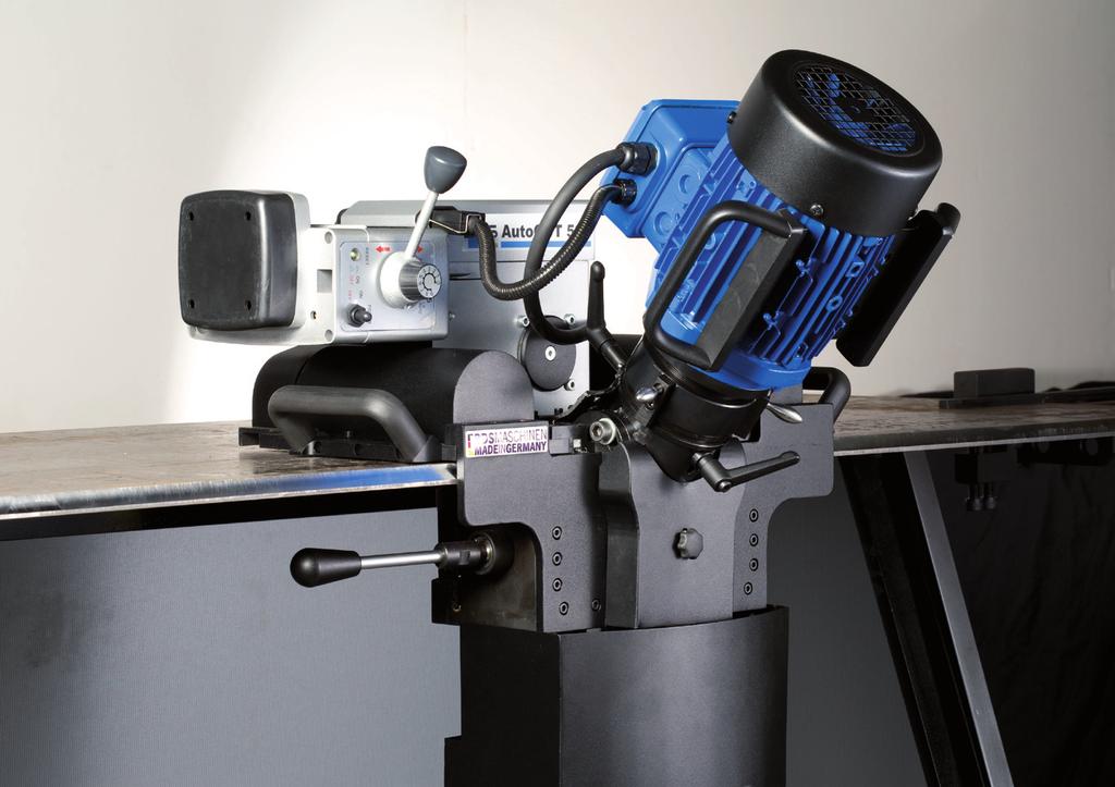
13 Components / delivery contents Components / delivery contents Machine overview Feed unit 6 Swarf guard 2 Milling head locking mechanism 7 Swarf bin 3 Milling motor 8 Milling angle setting 4 Milling motor carrying handle 9 Switch lever for the guide roller 5 Setting the cutting depth 10 Carrying handle 13
14 Components / delivery contents Accessories A A Left guide rail Torx pin spanner (not illustrated) Right guide rail (not illustrated) Transport case (not illustrated) Retaining pin (not illustrated) Operating instructions (not illustrated) 14

15 Components / delivery contents Operating elements RESET: reset after triggering of the circuit breaker 31 Milling motor on/off switch 22 Feed direction switchover 9 23 Feed motor rotation speed setting 24 Feed motor on/off switch 9 Switch lever for the guide roller 15
16 Before using for the first time Before using for the first time Transport inspection As standard, the machine is supplied with the components indicated in the section "Components/delivery contents". NOTE Check for visible signs of damage or missing items on delivery. Report an incomplete or damaged delivery to your supplier/retailer immediately. Checking the rotation direction of the milling motor The machine may only be operated with a clockwise rotating field. To check, proceed as follows: Insert the plug into the mains socket. Switch on the machine briefly, see section Switching the machine on/off. Check the rotation direction (clockwise) of the milling motor Danger Danger from electric current! Contact with live wires or components could lead to serious injury or even death! Observe the following safety precautions to avoid any danger from electric current: Ask a qualified electrician to check that the mains socket is able to supply a clockwise rotating field. 16
17 Milling with the machine Milling with the machine For milling, proceed as follows: Align the workpiece to be processed horizontally and secure it. CAUTION Potential damage to property if the machine is improperly used! Observe the following instructions to avoid damage: Lay the connecting cable in such a way that it cannot be caught by the running machine. Position the machine at the workpiece, see section Positioning the machine. Mount the guide rails, see section Mounting the guide rails. Set the milling angle and the cutting depth, see section Setting the milling angle and Setting the cutting depth. Set the feed, see section Setting the feed. Set the swarf guard and mount the swarf bin, see section Setting the swarf guard and Setting the swarf bin. Switch on the machine, see section Switching the machine on/off. NOTE Observe the following instructions: Pay attention to the production of swarf. Empty and clean the swarf bin regularly. The feed motor switches itself off after reaching the end position. Switch off the machine, see section Switching the machine on/off. NOTE Observe the following instructions: The chamfer width is dependent on the chamfer angle and the cutting depth set. Refer to the table on page 30 for setting values. 17
18 Setting up Setting up Safety measures This section contains important instructions on required preparation before starting setup work. WARNING Risk of injury from a falling machine. Observe the following safety instructions to avoid any danger. The machine may only be operated in a horizontal position. Secure the workpiece. Checking the properties of the workpiece The surface of the workpiece must meet the following requirements: The surface must be smooth and may not have any burn points, slag, welding joints or similar. NOTE Before beginning with milling, remove surface unevenness. 18

19 Setting up Positioning the machine WARNING Danger resulting from the heavy weight of the machine! Due to the heavy weight of the machine, observe the following instructions Only transport the machine with a suitable means of transport. Lifting the machine manually should be carried out by two persons. When transporting the machine with a crane, use suitable lifting equipment. Pay attention to the carrying capacity of the lifting equipment Move the milling head to the upper end position, see section Resetting the milling head. Loosen the lock nut (4) and the thumb screw (3). Position the machine at the edge of the workpiece (6) and push the stop plate (2) up to the working edge. Turn the thumb screw (3) until the castors (6) touch the workpiece and then make a further half turn. Secure the thumb screw with the lock nut (4). Check for free movement of the guide roller (5) switch lever. If necessary, loosen the thumb screw (3) slightly. 19

20 Setting up Mounting the guide rails NOTE Mount the left guide rail on the left side of the workpiece and the right guide rail on the right side of the workpiece Mount the guide rails onto the workpiece. Switch on the feed and move the machine to the end position. The guide rails are then automatically aligned. Align the guide rail so that the rail (3) is in line with the guide (2) of the machine. Tighten both fastening screws (1) until they touch the workpiece. The rail should still be movable. Switch on the feed, move the machine away from the guide rail and switch off the feed. Pay attention to the position of the guide roller (8) switch lever, see section Setting the feed. Check whether the guide rail is at the side of the workpiece edge. Tighten both fastening screws (1). If the guide rail is not at the same height as the workpiece surface, align it, see section Aligning the guide rail. Repeat the procedure for the other guide rail. 20
21 Setting up Aligning the guide rail 1 Remove each of the 2 fastening screws (1) on both sides of the guide rail. Adjust the height of the guide rail to the height of the workpiece surface. Tighten the 4 fastening screws (1). Setting the milling head 1 Move the milling head to the upper end position, see section Resetting the milling head. Move the swarf guard to the lower position. Remove the locking mechanism (1) on both sides of the milling unit. Set the desired milling angle. Tighten the locking mechanism (1) on both sides of the milling unit. 21
 clockwise (A) up the stopper.")
22 Setting up Setting the cutting depth Resetting the milling head Remove both clamping levers (1) on the upper and lower side of the milling unit. 2 A B Turn the setting ring (2) clockwise (A) up the stopper. 22
23 Tool change Setting the cutting depth Turn the setting ring (2) anticlockwise (B) until the milling head touches the workpiece. Switch on the feed and move the machine to the left end position. Set the desired cutting depth by turning the setting ring (2) anticlockwise (B). NOTE A complete turn corresponds to a setting of 1.5 mm. Tighten both clamping levers on the upper and lower side of the milling unit. Tool change WARNING Risk of injury! Do not use damaged, soiled or worn tools. Only perform tool changing when the machine is switched off and not moving. Pull the plug out of the mains socket. Only use tools, adapter and accessories that match the machine. 23

 upwards and pull the plug out.")


24 Tool change Dismantle the milling unit NOTE Dismantling the milling head is not necessary when changing or turning the reverse plates. Move the swarf guard to the lower position. Press the spring bracket (1) upwards and pull the plug out Unscrew the four fastening screws (2). Remove the milling unit from above. 3 Insert the retaining pin into the opening (3) to lock the spindle. Turn the shaft until the retaining pin snaps into the shaft. 4 5 Remove the fastening screws (5) and remove the milling head (4). 24
, turn the reversing plate (1) and tighten the fastening screw (2).")
25 Tool change Turning the reversing plates 1 Replacing the reversing plate Mounting the milling unit 2 Dismantle the milling unit, see section Dismantling the milling unit. Turn back the setting ring until you can remove the reversing plates with a Torx pin spanner. Remove the fastening screws (2), turn the reversing plate (1) and tighten the fastening screw (2). Repeat this work step for all reversing plates of the milling head. When the reversing plate is completely worn, it must be replaced by a new one: Unscrew the fastening screw (2) and remove the reversing plate. Insert the reversing plate and tighten the fastening screws again. Pull out the retaining pin Insert the milling unit into the machine and tighten the four fastening screws. 25
 to position 1 to switch on the machine. Move the on/off switch (31) to position 0 to switch off the machine.")
 forwards or backwards according to the desired feed direction: feed direction from left to right = position A (front)")
26 Operation Operation Switching the machine ON/OFF CAUTION Before switching on, check whether the retaining pin has been removed. Move the on/off switch (31) to position 1 to switch on the machine. Move the on/off switch (31) to position 0 to switch off the machine. Setting the feed Feed direction 9 A B Push the lever (22) on the feed unit to the left or to the right to set the corresponding feed unit on the drive. Push the guide roller switch lever (9) forwards or backwards according to the desired feed direction: feed direction from left to right = position A (front) feed direction from right to left = position B (back) 26
 and increase stepwise as necessary, depending on the cutting depth. Processing always takes place from left to right.")
27 Operation Feed rate Set the desired feed rate by turning the regulator (23):clockwise: increase rate, anticlockwise: decrease rate NOTE Switch feed motor on/off Resetting the feed motor Begin the milling procedure with a low feed rate (stage 2) and increase stepwise as necessary, depending on the cutting depth. Processing always takes place from left to right. The return takes place without infeed. Move the on/off switch (24) to the ON position to switch on the feed motor. Move the on/off switch (24) to the OFF position to switch off the feed motor. Press the RESET button (21) to reset the feed motor controller, e.g., after triggering the motor circuit breaker. 27
.")
28 Operation Setting the swarf guard WARNING Risk of injury from swarf spinning out. Only operate the machine with correctly mounted swarf guard. 1 2 Remove the rotary knob (2). Push the swarf guard (1) upwards to the stopper. Tighten the rotary knob (2). 28

29 Operation Mounting the swarf bin WARNING Risk of injury from swarf spinning out. Only operate the machine with a correctly mounted swarf bin. 1 Insert both pins (1) into the holes on the underneath of the milling unit. 29
30 Eliminating blockages Chamfer width/milling angle ratio A B C Chamfer width B [mm] Milling angle A Cutting depth C [mm] Eliminating blockages WARNING Put protective gloves on before starting work. Switch off the machine and pull the plug out of the mains socket. Release the workpiece from the machine. Remove swarf and check the milling head. 30
31 Cleaning Cleaning WARNING Switch off the machine and pull the plug out of the mains socket before starting maintenance and cleaning. Due to the risk of injury to persons or damage to the machine, cleaning with compressed air is prohibited. CAUTION Never immerse the machine in water or other liquids. After every use Remove the swarf bin. Empty and clean the swarf bin Remove swarf on the machine. Clean the tools and the brushes on the underneath of the milling unit. Move the milling head to the upper end position, see section Resetting the milling head. Tighten both clamping levers on the upper and lower side of the milling unit. Clean the guide rollers. Put the machine and accessories into the transport case. 31

32 Maintenance Maintenance WARNING Danger caused by unqualified repairs! Unqualified repairs can lead to considerable danger for the user and cause damage to the machine. Repairs to electrical appliances may only be carried out by the works customer service or by specialists trained by the manufacturer. Check the following machine parts regularly for wear: Milling head and reversing plates Castors Brushes Pressure plates on the front stopping plate Feed unit v-belt; re-tension, if necessary. Setting the v-belt tension Remove the v-belt cover To remove the v-belt cover, proceed as follows Remove the fastening screws (1). Remove the cover (2). 32
33 Maintenance 1 1 To set the v-belt tension, proceed as follows: Remove the fastening screws (1) of the counter-pressure rollers for the left or right v-belt. Set to the desired v-belt tension by raising or lowering the counter roller. Tighten the fastening screw (1) again. Fix the cover with both fastening screws. 33
34 Troubleshooting Replacing the v-belt To replace the v-belt, proceed as follows: Remove the v-belt cover, see section Removing the v-belt cover Remove the fixing screw (1) for the counter-pressure rollers for both v-belts and move the counter-pressure rollers to the lower position. Unscrew the fastening screw (2) and both grub screws (6). Remove the five fastening screws (4) and take off the guide rail (5). Customer service/service Pull off the three drive rollers (3). Remove the old v-belt and put in a new v-belt. Attach the drive rollers (3). Mount the guide rail (5) and tighten the fastening screws (4). Screw in the grub screws (6) and the fastening screws (2). Set the v-belt tension, see section Setting the v-belt tension. If you have any questions for customer service/service, please contact BDS. 34
35 Troubleshooting Troubleshooting Fault causes and remedies Fault Possible cause Remedy The milling motor does not start after the on/off switch is pressed or stops during operation. Plug not inserted into socket. Automatic circuit breaker tripped. Insert the plug. Switch on the automatic circuit breaker again. The automatic circuit breaker in the electrical distribution board trips The feed does not work. Too many devices connected to the same power circuit. The machine is defective. Cutting depth is too large. The feed motor plug is not inserted. The feed motor circuit breaker was tripped. V-belt tension too low. V-belt is damaged. Reduce the number of devices on the power circuit. Contact customer service. Reduce the cutting depth Insert the feed motor plug. Eliminate the cause for overloading of the feed motor and press the RESET button (21). Increase the v-belt tension. Replace the v-belt. NOTE If you cannot resolve the problem with the steps described above, please contact customer service. 35

36 Storage/disposal Storage/disposal Storage If you do not intend to use the machine for a longer period of time, clean it as described in the section Cleaning. Store the machine and all its accessories in the transport case at a dry, clean and frost-free location. Disposal Disposal of the packaging The packaging protects the machine against damage during transit. The packaging materials were selected according to environmental and waste disposal aspects and can therefore be recycled. Recycling the packaging material for further use saves raw materials and reduces waste. When no longer required, dispose of the packaging materials in accordance with the local regulations. Disposal of the old machine This product may not be disposed of in the domestic refuse within the European Union. Dispose of the machine in accordance with the EC Directive 2002/96/EC-WEEE (Waste Electrical and Electronic Equipment). Should you have any questions, please contact your local authority responsible for waste disposal. 36
37 Appendix Appendix Technical data Model Dimensions (L x W x H) Net weight, approx. Operating voltage Power Noise emission Rotating speed Feed Chamfer angle Chamfer width Cutting tool Thermal protection Workpiece thickness, max. Connecting cable length Protection class 600 x 500 x 540 mm 50 kg 400 VAC / 50 Hz 1100 W db(a) 2750 rpm Automatic, continuously variable up to max. 500 mm/min 15 to 60 (continuously variable) max. 30 mm Face milling head with hard metal cutting inserts Yes 40 mm 2.8 m I 37
38 Appendix EC Declaration of Conformity Name/address of the manufacturer: BDS Maschinen GmbH Martinstraße 108 D Mönchengladbach We hereby declare that the product Model: Welding edge milling machine Type: conforms to the following relevant regulations: EC Directive 2006/42/EC on machinery EU Directive 2004/108/EU on Electromagnetic Compatibility. The following harmonised standards were applied in whole or in part: DIN EN ISO DIN EN ISO DIN EN DIN EN DIN EN DIN EN DIN EN DIN EN Responsible person for documentation according to EC Directive 2006/42/EC - Annex II Pt.A.2. was: (Surname, forename, position in company of the manufacturer) Mönchengladbach, 3rd May, 2011 Wolfgang Schröder, Technical Director (Legally binding signature of the issuer) 38
39
40 BA_AUTOCUT500_0111_A BDS Maschinen GmbH BDS Maschinen GmbH Martinstraße 108 D Mönchengladbach Fon: +49 (0) 2161 / Fax: +49 (0) 2161 / Internet: info@bds-maschinen.de
Tube Facing Tool.
 www.swagelok.com Tube Facing Tool This manual contains important information for the safe and effective operation of the Swagelok TF72 series tube facing tool. Users should read and understand its contents
Knife grinding machine K3 H/K
 Knife grinding machine K3 H/K 01.11.2010 GS-Schleiftechnik, Leyher Str. 61 a, D-90431 Nürnberg Phone 0049/9193/4404, Fax 0049/9193/4391 e-mail: info@gs-de.eu 1 Table of Contents A. SAFETY... 3 A.1 THE
GENERAL OPERATIONAL PRECAUTIONS PRECAUTIONS ON USING DISC GRINDER
 GENERAL OPERATIONAL PRECAUTIONS WARNING! When using electric tools, basic safety precautions should always be followed to reduce the risk of fire, electric shock and personal injury, including the following.
Auto Feed Screwdriver
 ENGLISH Auto Feed Screwdriver MODEL 6833 MODEL 6834 MODEL 6836 002607 DOUBLE INSULATION I N S T R U C T I O N M A N U A L WARNING: For your personal safety, READ and UNDERSTAND before using. SAVE THESE
INSTRUCTION BOOKLET AND WARRANTY INFORMATION 6 BENCH GRINDER
 INSTRUCTION BOOKLET AND WARRANTY INFORMATION 6 BENCH GRINDER Part No.: SW1250 PLEASE READ CARE AND SAFETY INSTRUCTIONS BEFORE USE SPECIFICATIONS Part No.: SW1250 Input Voltage: 240V Frequency: 50Hz Rated
Recipro Saw MODEL JR3020. WARNING: For your personal safety, READ and UNDERSTAND before using. SAVE THESE INSTRUCTIONS FOR FUTURE REFERENCE.
 ENGLISH Recipro Saw MODEL JR3020 002479 DOUBLE INSULATION I N S T R U C T I O N M A N U A L WARNING: For your personal safety, READ and UNDERSTAND before using. SAVE THESE INSTRUCTIONS FOR FUTURE REFERENCE.
VARIABLE SPEED WOOD LATHE
 MODEL MC1100B VARIABLE SPEED WOOD LATHE INSTRUCTION MANUAL Please read and fully understand the instructions in this manual before operation. Keep this manual safe for future reference. Version: 2015.02.02
OPERATOR S MANUAL DRILLING MACHINE WITH ELECTROMAGNETIC BASE
 OPERATOR S MANUAL DRILLING MACHINE WITH ELECTROMAGNETIC BASE UNIT 30 NEWHALLHEY BUSINESS PARK, NEWHALLHEY RD, RAWTENSTALL, ROSSENDALE, LANCASHIRE BB4 6HR Tel. +44 1706 229490, fax. +44 1706 830496 www.jeiuk.com
Drill INSTRUCTION MANUAL. WARNING: For your personal safety, READ and UNDERSTAND before using. SAVE THESE INSTRUCTIONS FOR FUTURE 1 REFERENCE.
 ENGLISH (Original instructions) INSTRUCTION MANUAL Drill 6411 6412 6413 007894 DOUBLE INSULATION WARNING: For your personal safety, READ and UNDERSTAND before using. SAVE THESE INSTRUCTIONS FOR FUTURE
 GENERAL OPERATIONAL PRECAUTIONS WARNING! When using electric tools, basic safety precautions should always be followed to reduce the risk of fire, electric shock and personal injury, including the following.
GENERAL OPERATIONAL PRECAUTIONS PRECAUTIONS ON USING CUT-OFF MACHINE
 GENERAL OPERATIONAL PRECAUTIONS WARNING! When using electric tools, basic safety precautions should always be followed to reduce the risk of fire, electric shock and personal injury, including the following.
VARIABLE SPEED WOOD LATHE. Model DB900 INSTRUCTION MANUAL
 VARIABLE SPEED WOOD LATHE Model DB900 INSTRUCTION MANUAL 1007 TABLE OF CONTENTS SECTION...PAGE Technical data.. 1 General safety rules....1-3 Specific safety rules for wood lathe.....3 Electrical information.4
Bending Roll Machine 4126
 Bending Roll Machine 4126 Operating Instructions Table of contents Main components...4 Operation...5 Safety...7 Service and maintenance... 12 Machine plates and stickers... 13 Dismantling the bending
Nibbler MODEL JN1601. WARNING: For your personal safety, READ and UNDERSTAND before using. SAVE THESE INSTRUCTIONS FOR FUTURE REFERENCE.
 ENGLISH Nibbler MODEL JN60 00477 DOUBLE INSULATION I N S T R U C T I O N M A N U A L WARNING: For your personal safety, READ and UNDERSTAND before using. SAVE THESE INSTRUCTIONS FOR FUTURE REFERENCE. SPECIFICATIONS
Quick Set Dovetail Jig
 Quick Set Dovetail Jig FOR HELP OR ADVISE ON THIS PRODUCT PLEASE CALL OUR CUSTOMER SERVICE HELP LINE : 01509 500359 THE MANUFACTURER RESERVES THE RIGHT TO ALTER THE DESIGN OR SPECIFICATION TO THIS PRODUCT
Operator Manual. Booklet Maker BM 60. Doc No. T10171
 Booklet Maker BM 60 Operator Manual Doc No. T10171 Morgana Systems Limited United Kingdom www.morgana.co.uk Telephone: ( 01908 ) 608888 Facsimile: ( 01908 ) 692399 Part no: 60249 Doc no: T10171 Rev. date:
Cut-Off Machine Model CC 14SE
 Cut-Off Machine Model CC 14SE Handling instructions NOTE: Before using this Electric Power Tool, carefully read through these HANDLING INSTRUCTIONS to ensure efficient, safe operation. It is recommended
CHAINSAW SHARPENER MODEL: ECSS-1
 CHAINSAW SHARPENER MODEL: ECSS-1 Part No: 3402075 ASSEMBLY & INSTRUCTION MANUAL LS0409 INTRODUCTION Thank you for purchasing this CLARKE product Before attempting to use the product, it is essential that
Tapping Screw (W/Flange) 46 Cord Armor 47 Tube (D) 48 Cord. 45 Cord Clip. Tapping Screw (W/Flange) 10 Gear Cover Ass'y. 12 Socket (B) Ass'y
 46 Cord Armor 47 Tube (D) 48 Cord. 45 Cord Clip. Tapping Screw (W/Flange) 10 Gear Cover Ass'y. 12 Socket (B) Ass'y") W8VB The exploded assembly drawing should be used only for authoized service center. W8VB Item No. Part time 1 Magnetic Hex. Socket 2 Sub Stopper 3 O-Ring (S-16) 4 Locator (A) 5 Lock Sleeve (A) 6 O-Ring
W8VB The exploded assembly drawing should be used only for authoized service center. W8VB Item No. Part time 1 Magnetic Hex. Socket 2 Sub Stopper 3 O-Ring (S-16) 4 Locator (A) 5 Lock Sleeve (A) 6 O-Ring
ENGLISH (Original instructions) INSTRUCTION MANUAL. Drill DS4012 DOUBLE INSULATION. IMPORTANT: Read Before Using.
 INSTRUCTION MANUAL. Drill DS4012 DOUBLE INSULATION. IMPORTANT: Read Before Using.") ENGLISH (Original instructions) INSTRUCTION MANUAL Drill DS402 05402 DOUBLE INSULATION IMPORTANT: Read Before Using. ENGLISH (Original instructions) SPECIFICATIONS Model DS402 Capacities Steel 3 mm Wood
ENGLISH (Original instructions) INSTRUCTION MANUAL Drill DS402 05402 DOUBLE INSULATION IMPORTANT: Read Before Using. ENGLISH (Original instructions) SPECIFICATIONS Model DS402 Capacities Steel 3 mm Wood
ENGLISH (Original instructions) INSTRUCTION MANUAL. Drill DOUBLE INSULATION. IMPORTANT: Read Before Using.
 INSTRUCTION MANUAL. Drill DOUBLE INSULATION. IMPORTANT: Read Before Using.") ENGLISH (Original instructions) INSTRUCTION MANUAL Drill 64 642 643 007894 DOUBLE INSULATION IMPORTANT: Read Before Using. ENGLISH (Original instructions) SPECIFICATIONS Model 64 642 643 Capacities Steel
ENGLISH (Original instructions) INSTRUCTION MANUAL Drill 64 642 643 007894 DOUBLE INSULATION IMPORTANT: Read Before Using. ENGLISH (Original instructions) SPECIFICATIONS Model 64 642 643 Capacities Steel
Electric Chainsaw Sharpener
 FPP CHAINSS Electric Chainsaw Sharpener Instruction Manual For your own safety, please ensure you have read these instructions before use and have fully understood all the safety guidelines. Specifications
Radio System Strobe Wizard Plus Freemask
 Radio System Strobe Wizard Plus Freemask User manual Translation of the original German user manual Doc. No.: 900.0509.00 Version: 09/2017 Contents Information about this manual and about the manufacturer...
UNIVERSAL WORKSTATION
 ASSEMBLY AND OPERATING INSTRUCTIONS UNIVERSAL WORKSTATION FOX Model F50-179 1 Universal Workstation FOX MODEL F50-179 TABLE OF CONTENTS Safety instructions Page 3 Specific safety instructions for workbenches..
18 GAUGE ELECTRIC METAL SHEAR
 241-9895 18 GAUGE ELECTRIC METAL SHEAR Operator s Manual SAVE THIS MANUAL You will need this manual for safety instructions, operating procedures and warranty. Put it and the original sales receipt in
Top spin Nr /
 Top spin Nr. 1840 0000 / 1840 1000 Bedienungsanleitung 21-6680 28052014 / A Made in Germany Ideas for dental technology Top spin Nr. 1840 0000 / 1840 1000 Contents 1. Introduction...2 1.1 Symbols...2 2.
ENGLISH (Original instructions) INSTRUCTION MANUAL. Drill MT600 MT601 DOUBLE INSULATION. IMPORTANT: Read Before Using.
 INSTRUCTION MANUAL. Drill MT600 MT601 DOUBLE INSULATION. IMPORTANT: Read Before Using.") ENGLISH (Original instructions) INSTRUCTION MANUAL Drill MT600 MT60 003635 DOUBLE INSULATION IMPORTANT: Read Before Using. ENGLISH (Original instructions) SPECIFICATIONS Model MT600 MT60 Capacities Steel
ENGLISH (Original instructions) INSTRUCTION MANUAL Drill MT600 MT60 003635 DOUBLE INSULATION IMPORTANT: Read Before Using. ENGLISH (Original instructions) SPECIFICATIONS Model MT600 MT60 Capacities Steel
Impact Wrench MODEL 6905B MODEL 6906
 ENGLISH Impact Wrench MODEL 6905B MODEL 6906 005305 DOUBLE INSULATION I N S T R U C T I O N M A N U A L WARNING: For your personal safety, READ and UNDERSTAND before using. SAVE THESE INSTRUCTIONS FOR
12mm (Max) 6mm (Max) 82mm (Max) 12mm (Max) 6mm (Max)
 6mm (Max) 82mm (Max) 12mm (Max) 6mm (Max)") 1 1 2 2 3 3 82mm (Max) 12mm (Max) 12mm (Max) 6mm (Max) 4 4 5 6 8 6mm (Max) 0.5 0mm 1 5 6 7 7 8 9 9 A = B 10 11 12 D B 1 13 14 15 0 C A D E 16 17 18 F G D B N H J G I K 19 A 20 G L 21 C K 1mm L M 1mm 22
1 1 2 2 3 3 82mm (Max) 12mm (Max) 12mm (Max) 6mm (Max) 4 4 5 6 8 6mm (Max) 0.5 0mm 1 5 6 7 7 8 9 9 A = B 10 11 12 D B 1 13 14 15 0 C A D E 16 17 18 F G D B N H J G I K 19 A 20 G L 21 C K 1mm L M 1mm 22
Operating Instructions K-POWERgrip EWL Always on the safe site.
 Operating Instructions K-POWERgrip EWL 4941. Always on the safe site. KaVo Elektrotechnisches Werk GmbH Wangener Straße 78 D-88299 Leutkirch A 1 User information...2 A 1.1 Meaning of the pictograms...2
GENERAL OPERATIONAL PRECAUTIONS
 GENERAL OPERATIONAL PRECAUTIONS WARNING! When using electric tools, basic safety precautions should always be followed to reduce the risk of fire, electric shock and personal injury, including the following.
GEARED HEAD DRILL / MILL MACHINE INSTRUCTION MANUAL
 www.industrialtool.com.au GEARED HEAD DRILL / MILL MACHINE INSTRUCTION MANUAL READ CAREFULLY AND UNDERSTAND THESE INSTRUCTIONS BEFORE USE. LIMITED WARRANTY Industrial Tool & Machinery Sales (hereinafter
High Speed Drill MODEL WARNING: For your personal safety, READ and UNDERSTAND before using. SAVE THESE INSTRUCTIONS FOR FUTURE REFERENCE.
 ENGLISH High Speed Drill MODEL 6501 003002 DOUBLE INSULATION I N S T R U C T I O N M A N U A L WARNING: For your personal safety, READ and UNDERSTAND before using. SAVE THESE INSTRUCTIONS FOR FUTURE REFERENCE.
ENGLISH (Original instructions) INSTRUCTION MANUAL. Shear Wrench 6922NB DOUBLE INSULATION. IMPORTANT: Read Before Using.
 INSTRUCTION MANUAL. Shear Wrench 6922NB DOUBLE INSULATION. IMPORTANT: Read Before Using.") ENGLISH (Original instructions) INSTRUCTION MANUAL Shear Wrench 69NB 00498 DOUBLE INSULATION IMPORTANT: Read Before Using. ENGLISH (Original instructions) SPECIFICATIONS Model 69NB Bolt size M6, M0, M
ENGLISH (Original instructions) INSTRUCTION MANUAL Shear Wrench 69NB 00498 DOUBLE INSULATION IMPORTANT: Read Before Using. ENGLISH (Original instructions) SPECIFICATIONS Model 69NB Bolt size M6, M0, M
Power Planer 1900B/N1900B/1902
 Power Planer 1900B N1900B 1902 SPECIFICATIONS Model 1900B/N1900B/1902 Planing width... 82 mm Planing depth... 1 mm Shiplapping depth... 9 mm No load speed (min -1 )...16,000 Overall length... 290 mm Net
Angle Grinder MODEL 9553B MODEL 9555B
 ENGLISH Angle Grinder MODEL 9553B MODEL 9555B 006649 DOUBLE INSULATION I N S T R U C T I O N M A N U A L WARNING: For your personal safety, READ and UNDERSTAND before using. SAVE THESE INSTRUCTIONS FOR
ROTARY HAMMER OWNER'S MANUAL
 ROTARY HAMMER OWNER'S MANUAL WARNING: Read carefully and understand all INSTRUCTIONS before operating. Failure to follow the safety rules and other basic safety precautions may result in serious personal
- 4 - Fig. 3b. Fig. 1b. Fig. 2. Fig. 2b MT 300
 MP 00 Manual 1 7 6 9 8 5 1 1 10 11 1 Fig. 1a Fig. 1b MT 00 Breite Buche Erle Pappel Balsa 0 0,5 0,8 0,8 0,8 max. Zustellung mm 0 0, 0,6 0,8 0,8 60 0, 0, 0, 0,8 80 0,1 0,1 0, 0,6 n Messerwelle = 6.000/min
ATBG280/6 Bench Grinder Bench Grinder ATBG280/6 230V-50Hz 280 Watt 150mm x 25mm Wheel size
 Bench Grinder ATBG280/6 230V-50Hz 280 Watt 150mm x 25mm Wheel size SPECIFICATIONS Model Number : ATBG280/6 Nominal Voltage Power Consumption No load speed Wheel size Weight 230Volt 50Hz 280 Watts 2880
Auto Feed Screwdriver
 ENGLISH (Original instructions) INSTRUCTION MANUAL Auto Feed Screwdriver 684 6843 6844 6846 0080 DOUBLE INSULATION IMPORTANT: Read Before Using. ENGLISH (Original instructions) SPECIFICATIONS Model 684
GENERAL OPERATIONAL PRECAUTIONS
 GENERAL OPERATIONAL PRECAUTIONS WARNING! When using electric tools, basic safety precautions should always be followed to reduce the risk of fire, electric shock and personal injury, including the following.
Subject to change. USERS MANUAL Art.nr. PRM6006 PBF-1050N
 UK Subject to change UK USERS MANUAL Art.nr. PRM6006 PBF-1050N 0406-14 EXPLODED VIEW Fig. D Fig. A Fig. E Fig. B Fig. F Fig. C Fig. G 2 Powercraft Powercraft 11 SPARE PARTS LIST PBF-1050N REF NR DESCRIPTION
Hammer Drill MODEL HP1500 MODEL HP1501 MODEL HP1510
 ENGLISH Hammer Drill MODEL HP500 MODEL HP50 MODEL HP50 002395 DOUBLE INSULATION I N S T R U C T I O N M A N U A L WARNING: For your personal safety, READ and UNDERSTAND before using. SAVE THESE INSTRUCTIONS
Operator's manual. TruTool N 200 (1A1) english
 english") Operator's manual TruTool N 200 (1A1) english Table of contents 1. Safety...3 2. Description...5 2.1 Correct use...6 2.2 Technical data...7 3. Tool assembly...8 3.1 Changing the stroke rate...8 4. Operation...10
Operator's manual TruTool N 200 (1A1) english Table of contents 1. Safety...3 2. Description...5 2.1 Correct use...6 2.2 Technical data...7 3. Tool assembly...8 3.1 Changing the stroke rate...8 4. Operation...10
Operating Instructions
 02 ENG 28.01.2008 9:14 Uhr Seite 11 Contents 1 Declaration of Compliance 2 Proper Use 3 Overview 4 General Safety Rules 5 Specific Safety Rules 6 Operation 6.1 Switching the paint remover On/Off 6.2 Locking
Operating manual. TruTool N 500 (1A1) english
 english") Operating manual TruTool N 500 (1A1) english Table of Contents 1. Safety...4 1.1 General safety information...4 1.2 Specific safety information...5 2. Description...6 2.1 Correct use...7 2.2 Technical
Operating manual TruTool N 500 (1A1) english Table of Contents 1. Safety...4 1.1 General safety information...4 1.2 Specific safety information...5 2. Description...6 2.1 Correct use...7 2.2 Technical
Instruction Manual 13MM DRILL PRESS. Model SROM1199. Our tool range has you covered for DIY. Whatever the job, make light work of it with MAKO tools.
 Instruction Manual 13MM DRILL PRESS Model SROM1199 Our tool range has you covered for DIY. Whatever the job, make light work of it with MAKO tools. PRODUCT FEATURES: 1. Pulley Cover 9. Feed Handle 2. Motor
OPERATION AND MAINTENANCE MANUAL fervi.com Riveter for threaded inserts Art ORIGINAL INSTRUCTIONS
 OPERATION AND MAINTENANCE MANUAL Riveter for threaded inserts Art. 0469 ORIGINAL INSTRUCTIONS FOREWORD Read this manual before operation ORIGINAL INSTRUCTIONS Before starting any operation it is compulsory
ATD AMP Variable Speed Reciprocating Saw Owner s Manual
 ATD-10535 7 AMP Variable Speed Reciprocating Saw Owner s Manual Manufactured in China To ATD Tools, Inc. Specifications TECHNICAL SPECIFICATIONS Voltage: 120V Frequency: 60Hz Power input: 7 Amps No load
Operation Manual ARTICEL 51251
 Operation Manual ARTICEL 51251 Read and follow the operating instructions and safety information before using for the first time. Technical changes reserved! Due to further developments, illustrations,
Electric Log Splitter 9241
 Electric Log Splitter 9241 Instructions Contents Before you start 1 Proper use of the product 1 What are the meanings of the symbols used? 1 An overview of your machine 2 Protective mechanisms 2 Assembling
KR703-XE KR704-XE KR705-XE KR753-XE KR754-XE KR755-XE Australia New Zealand
 6 5 4 www.blackanddecker.com.au 3 7 2 1 8 KR703-XE KR704-XE KR705-XE KR753-XE KR754-XE KR755-XE Australia New Zealand 7 8 A 12 13 10 9 10 B C 11 7 8 D E 2 Intended use Your Black & Decker hammer drill
Drill MODEL 6013B MODEL 6013BR. WARNING: For your personal safety, READ and UNDERSTAND before using. SAVE THESE INSTRUCTIONS FOR FUTURE REFERENCE.
 ENGLISH Drill MODEL 6013B MODEL 6013BR 004618 DOUBLE INSULATION I N S T R U C T I O N M A N U A L WARNING: For your personal safety, READ and UNDERSTAND before using. SAVE THESE INSTRUCTIONS FOR FUTURE
Table of contents. 2 Safety E517EN_03.DOC. 1. Safety Description Correct use Technical data F Lock seams...
 Table of contents 1. Safety...3 2. Description...5 2.1 Correct use...6 2.2 Technical data F 300-2...7 2.3 Lock seams...8 3. Tool assembly...10 3.1 Setting the tool...10 3.2 Machining of inner radiuses...11
S E L E C T I O N. Upper Back. User manual
 and S E L E C T I O N T H E S T R E N G T H E V O L U T I O N User manual and and The identification plate of the and manufacturer, affixed to the frame on the side opposite the padded rest, gives the
Angle Drill MODEL DA3000R MODEL DA3000V
 ENGLISH Angle Drill MODEL DA3000R MODEL DA3000V 003004 DOUBLE INSULATION I N S T R U C T I O N M A N U A L WARNING: For your personal safety, READ and UNDERSTAND before using. SAVE THESE INSTRUCTIONS FOR
S E L E C T I O N. Arm Curl. User manual
 S E L E C T I O N T H E S T R E N G T H E V O L U T I O N User manual The identification plate of the and manufacturer, affixed behind the seat, gives the following details: A Name and address of the manufacturer
ENGLISH (Original instructions) INSTRUCTION MANUAL. Drill MDP303 MDP304 DOUBLE INSULATION. IMPORTANT: Read Before Using.
 INSTRUCTION MANUAL. Drill MDP303 MDP304 DOUBLE INSULATION. IMPORTANT: Read Before Using.") ENGLISH (Original instructions) INSTRUCTION MANUAL Drill MDP303 MDP304 0876 DOUBLE INSULATION IMPORTANT: Read Before Using. ENGLISH (Original instructions) SPECIFICATIONS Model MDP303 MDP304 Capacities
ENGLISH (Original instructions) INSTRUCTION MANUAL Drill MDP303 MDP304 0876 DOUBLE INSULATION IMPORTANT: Read Before Using. ENGLISH (Original instructions) SPECIFICATIONS Model MDP303 MDP304 Capacities
Originalbetriebsanleitung 6. Original operating manual 11 Notice d utilisation d origine 16. Originele gebruiksaanwijzing 31 Originalbruksanvisning 36
 Festool Group GmbH & Co. KG Wertstraße 0 D-7340 Wendlingen Tel.: +49 (0)704/804-0 Telefax: +49 (0)704/804-0608 www.festool.com Originalbetriebsanleitung 6 Original operating manual Notice d utilisation
Cut-Off Machine CC 14SF. Read through carefully and understand these instructions before use. Handling instructions
 Cut-Off Machine CC 14SF Read through carefully and understand these instructions before use. Handling instructions GENERAL OPERATIONAL PRES WARNING! When using electric tools, basic safety precautions
planer/thicknesser 200 x 120mm
 instructions for planer/thicknesser 200 x 120mm model no: sm1311 Thank you for purchasing a Sealey product. Manufactured to a high standard, this product will, if used according to these instructions,
Operator's manual. TruTool TKF 1100 (1A1) TruTool TKF 1101 (1A1)
 TruTool TKF 1101 (1A1)") Operator's manual TruTool TKF 1100 (1A1) TruTool TKF 1101 (1A1) Table of contents 1 Safety 3 1.1 General safety information 3 1.2 Specific safety information for beveler 3 2 Description 5 2.1 Intended
Operator's manual TruTool TKF 1100 (1A1) TruTool TKF 1101 (1A1) Table of contents 1 Safety 3 1.1 General safety information 3 1.2 Specific safety information for beveler 3 2 Description 5 2.1 Intended
Operating Manual 6 Industrial Bench Grinder ATBG280/
 Operating Manual 6 Industrial Bench Grinder ATBG280/6 804531 40 Year Australian Heritage The reputable name in bench grinders for 40 years Protect yourself and others by observing all safety information,
Mortising Attachment
 Mortising Attachment Owner s Manual WARNING: Read carefully and understand all ASSEMBLY AND OPERATION INSTRUCTIONS before operating. Failure to follow the safety rules and other basic safety precautions
COJSAWBX Electric Jig Saw Assembly & Operating Instructions
 COJSAWBX Electric Jig Saw Assembly & Operating Instructions READ ALL INSTRUCTIONS AND WARNINGS BEFORE USING THIS PRODUCT. This manual provides important information on proper operation and maintenance.
Operator's manual TruTool PN 130 (1A1)
") Operator's manual TruTool PN 130 (1A1) english TruTool PN 130 (1A1) Table of Contents Table of Contents 1. Safety...4 1.1 1.2 General safety information...4 Specific safety information...5 2. Description...6
Operator's manual TruTool PN 130 (1A1) english TruTool PN 130 (1A1) Table of Contents Table of Contents 1. Safety...4 1.1 1.2 General safety information...4 Specific safety information...5 2. Description...6
BB Inch Double Cut Saw Assembly & Operating Instructions READ ALL INSTRUCTIONS AND WARNINGS BEFORE USING THIS PRODUCT.
 BB07552 5 Inch Double Cut Saw Assembly & Operating Instructions READ ALL INSTRUCTIONS AND WARNINGS BEFORE USING THIS PRODUCT. This manual provides important information on proper operation & maintenance.
Safety instructions and installation
 1 Safety instructions and installation Thank you for deciding to purchase the innovative Frama Starter / Matrix F10 / Matrix F12 franking system. The information below in this operating manual is intended
Dust Collector. Model No: DC2200 (FM300S)
") Dust Collector Model No: DC2200 (FM300S) GENERAL SAFETY INSTRUCTIONS Before attempting to operate this machine, it is important that you read, understand and follow these instructions very carefully. They
Dust Collector Model No: DC2200 (FM300S) GENERAL SAFETY INSTRUCTIONS Before attempting to operate this machine, it is important that you read, understand and follow these instructions very carefully. They
STEB 70 Quick STEB 80 Quick
 STEB 70 Quick STEB 80 Quick en Original instructions 9 www.metabo.com 15 16 17 14 13 12 11 10 30 mm 9 8 7 6 5 4 3 2 1 2 13. STEB 70 Quick STEB 80 Quick M Nm (inlbs) 6 (53.1) 6 (53.1) T 1 mm (in) 70 (2
SAFETY AND OPERATING MANUAL
 SAFETY AND OPERATING MANUAL BladeRunner X2 WX572 9 10 8 11 5 7 12 6 20 1 2 4 3 14 13 15 A2 A1 17 18 B2 B1 1 2 1 2 19 B3 3 4 2 C 1 D1 D1 C 2 1 E1 D2 1 2 E2 1 2 F G1 G1 F OFF ON G2 G3 H1 H2 I1 I2 I1 I2 J
2-Speed Hammer Drill HP2000 HP2020
 2-Speed Hammer Drill HP2000 HP2020 SPECIFICATIONS Model HP2000 HP2020 Speed High Low High Low Capacities Concrete 20 mm 20 mm Steel 6.5 mm 13 mm 6.5 mm 13 mm No load speed (min 1 ) 0 2,300 0 900 2,300
Operating Instructions PALLMANN Cobra II Sanding Machine
 Operating Instructions PALLMANN Cobra II Sanding Machine PALLMANN 14509 E. 33rd Place, Unit G Aurora CO 80011 720.374.4810 Fax 720.374.2113 www.pallmann.us Reproduction in whole or in part requires written
GMR 1 PROFESSIONAL. ÁU~²Ýœ ÈULM¼« Àπ ß Õ ŸË Õ Èß π Petunjuk-Petunjuk untuk Penggunaan HıÎng dõn s dùng Instructions d emploi. Operating Instructions
 609 40 44 - Buch Seite Dienstag,. Juni 004 :5 5 GMR PROFESSIONAL * Des idées en action. Operating Instructions Àπ ß Õ ŸË Õ Èß π Petunjuk-Petunjuk untuk Penggunaan HıÎng dõn s dùng Instructions d emploi
Impact Wrench WR 22SA HANDLING INSTRUCTIONS. Read through carefully and understand these instructions before use.
 Impact Wrench WR 22SA HANDLING INSTRUCTIONS Read through carefully and understand these instructions before use. 1 1 2 2 3 4 5 3 6 7 8 9 5 3 4 kg-m 80 N m 800 M22 70 (F 10T) 0 C 70 700 60 50 600 500 40
Operator's manual. TruTool N 1000 (1B1) english
 english") Operator's manual TruTool N 1000 (1B1) english Table of contents 1. Safety...4 1.1 General safety information...4 1.2 Specific safety information...5 2. Description...6 2.1 Intended use...7 2.2 Technical
Operator's manual TruTool N 1000 (1B1) english Table of contents 1. Safety...4 1.1 General safety information...4 1.2 Specific safety information...5 2. Description...6 2.1 Intended use...7 2.2 Technical
ANGLE GRINDER STAND USER GUIDE AFTER SALES SUPPORT
 ANGLE GRINDER STAND USER GUIDE Important: retain for future reference - please read carefully. Now you have purchased a WORKZONE product you can rest assured in the knowledge that as well as your 1 year
UK Subject to change PAG-125/1020 Angle Grinder
 Subject to change www.servotool.nl 0511-09 USERS MANUAL Art.nr.AGM6010 PAG-125/1020 Angle Grinder 3 6 5 2 4 1 Fig. A 8 7 12 2 6 Fig. B Fig. D Fig. C Fig. E 2 Powercraft EXPLODED VIEW Powercraft 15 SPARE
WARNING! Read and understand the entire instruction manual before attempting set-up or operation of this machine!
 ! WARNING! Read and understand the entire instruction manual before attempting set-up or operation of this machine! 1. This machine is designed and intended for use by properly trained and experienced
PAG-230/2100K Angle Grinder
 UK Subject to change UK USERS MANUAL Art.nr. AGM6011 PAG-230/2100K Angle Grinder Servotool Lingenstraat 6 8028 PM Zwolle NL www.ferm.com UK-0507-05 3 5 6 EXPLODED VIEW 4 2 8 1 Fig.1 7 12 11 + 4 10 9 8
MANUAL BEVELLING AND DEBURRING SYSTEM B10 ELECTRA
 MANUAL BEVELLING AND DEBURRING SYSTEM B10 ELECTRA Ord. no. 25300 (1 Phase 220V) 25301 (1 Phase 110V) Operation manual for the device SUBJECT TO CHANGE MAQUINARIA NOGVAL S.L. C. Borges Blanques nº 38 P.I.
ENGLISH (Original instructions) INSTRUCTION MANUAL. Curved Planer 1002BA DOUBLE INSULATION. IMPORTANT: Read Before Using.
 INSTRUCTION MANUAL. Curved Planer 1002BA DOUBLE INSULATION. IMPORTANT: Read Before Using.") ENGLISH (Original instructions) INSTRUCTION MANUAL Curved Planer 00BA 0059 DOUBLE INSULATION IMPORTANT: Read Before Using. ENGLISH (Original instructions) SPECIFICATIONS Model 00BA Planing width 0 mm Planing
ENGLISH (Original instructions) INSTRUCTION MANUAL Curved Planer 00BA 0059 DOUBLE INSULATION IMPORTANT: Read Before Using. ENGLISH (Original instructions) SPECIFICATIONS Model 00BA Planing width 0 mm Planing
Hedge Trimmer Attachment HA110 HA850 Complément Taille-haie HA110 HA850 Tijeras cortasetos (suplemento) HA110 HA850
 HA110 HA850") Operator s manual Manual d utalisation Manual de instrucciones Hedge Trimmer Attachment HA110 HA850 Complément Taille-haie HA110 HA850 Tijeras cortasetos (suplemento) HA110 HA850 GB FR ES KEY TO SYMBOLS
Operator s manual Manual d utalisation Manual de instrucciones Hedge Trimmer Attachment HA110 HA850 Complément Taille-haie HA110 HA850 Tijeras cortasetos (suplemento) HA110 HA850 GB FR ES KEY TO SYMBOLS
WUKO-SEAM HAMMER MODEL 1002B
 O P E R A T I N G I N S T R U C T I O N S for WUKO-SEAM HAMMER MODEL 1002B 1 0 0 2 B TABLE OF CONTENTS: Safety Instructions Page 3 General Technical Data Page 4 Pre-Fabrication Page 4 Before operation
Hinge Boring/Insertion Machine Set Up And Operation Instructions
 Hinge Boring/Insertion Machine Set Up And Operation Instructions Manufactured In The USA By: Thompson Industries, Inc. 1018 Crosby Avenue, Sycamore, IL. 60178-0127 Ph:815-899-6670 Fax:815-899-1918 Thank
MODEL 83 Pail Handler
 MORSE MFG. CO., INC. 727 West Manlius Street P.O. Box 518 East Syracuse, NY 13057-0518 Phone: 315-437-8475 Fax: 315-437-1029 Email: service@morsemfgco.com Website: www.morsemfgco.com COPYRIGHT 2005 MORSE
General Machine Instructions
 General Machine Instructions Cyclone Cyclone Plus Storm Storm Plus Note these instructions are based on the Cyclone machines, But the Cylinder Section is the same on the Storm Machines Tempest Tempest
Impact Wrench 6904VH 6905H INSTRUCTION MANUAL
 ENGLISH (Original instructions) INSTRUCTION MANUAL Impact Wrench 6904VH 6905H 005299 DOUBLE INSULATION WARNING: For your personal safety, READ and UNDERSTAND before using. SAVE THESE INSTRUCTIONS FOR FUTURE
Instruction manual for STA 1 sectional door operator
 Instruction manual for STA 1 sectional door operator Sectional door operator STA 1 / Rev. 0.3 1 GB 1. Contents 3. General safety instructions 1. Contents 2 2. Key to symbols 2 3. General safety instructions
EID~100-2RE IMPACT DRILL OWNER'SOPERATINGMANUAL
 EID~100-2RE IMPACT DRILL OWNER'SOPERATINGMANUAL CE @] - ----- -::.- - D K :)>OJ \ I I A E J ) \ I I L o A I I-c. I I )9.31 I I I Fig.4 '.\ ". I mmm mmm \ ---- L I I Fig. 5 I I Ma; H Fig.2 Fig.8 English
Rotary hammer WD WD W/1500W
 Rotary hammer WD011330030 WD011320036 1250W/1500W WD011330030/WD011320036 Thank you for purchasing a WIDO product. We are confident that you will appreciate the quality of the product and you will be entirely
PS /8 Inch Electric Drill Assembly & Operating Instructions
 PS07216 3/8 Inch Electric Drill Assembly & Operating Instructions READ ALL INSTRUCTIONS AND WARNINGS BEFORE USING THIS PRODUCT. This manual provides important information on proper operation & maintenance.
Recipro Saw MODEL JR3000V. WARNING: For your personal safety, READ and UNDERSTAND before using. SAVE THESE INSTRUCTIONS FOR FUTURE REFERENCE.
 ENGLISH Recipro Saw MODEL JR3000V 00477 DOUBLE INSULATION I N S T R U C T I O N M A N U A L WARNING: For your personal safety, READ and UNDERSTAND before using. SAVE THESE INSTRUCTIONS FOR FUTURE REFERENCE.
Cordless Power Planer
 ENGLISH Cordless Power Planer MODEL 050D 00540 I N S T R U C T I O N M A N U A L WARNING: For your personal safety, READ and UNDERSTAND before using. SAVE THESE INSTRUCTIONS FOR FUTURE REFERENCE. SPECIFICATIONS
PAG-230/2100K Angle Grinder
 Subject to change USERS MANUAL Art.No. AGM6015 10/06 PAG-230/2100K Angle Grinder www.servotool.nl /IRE-0705-15 3 5 6 Exploded view 4 2 8 1 7 Fig.1 12 11 + 4 10 9 8 3 Fig.2 Fig.4 14 13 7 Fig.3 Fig.5 02
x 43 Wood Lathe
 Please dispose of packaging for the product in a responsible manner. It is suitable for recycling. Help to protect the environment, take the packaging to the local amenity tip and place into the appropriate
OPERATING INSTRUCTIONS
 GB OPERATING INSTRUCTIONS Automatic Wedge Welding Machine Please read operating instructions carefully before use and keep for further reference. APPLICATION The is an automatic wedge welding machine for
OPERATING INSTRUCTIONS 5-AXIS CLAMPING SYSTEM + ACCESSORIES
 OPERATING INSTRUCTIONS 5-AXIS CLAMPING SYSTEM + ACCESSORIES 1 Contents 1. Introduction 2. Safety instructions and precautions 3 Operating the clamp 3.1 Clamp set up 3.2 Sequence for clamp set up 3.3 Adjusting
VARIABLE SPEED LATHE
 VARIABLE SPEED LATHE Model No CWL325V Part No 6501660 OPERATING & MAINTENANCE INSTRUCTIONS GC0214 INTRODUCTION Thank you for purchasing this CLARKE Wood Lathe. Before attempting to operate the machine,
Handling instructions
 Hand Shear Model CE 16SA Handling instructions Note: Before using this Electric Power Tool, carefully read through these HANDLING INSTRUCTIONS to ensure efficient, safe operation. It is recommended that