G.W. Lisk Co., Inc. Workmanship Manual DOC Rev 3
|
|
|
- Donald Malone
- 5 years ago
- Views:
Transcription
1 G.W. Lisk Co., Inc. Workmanship Manual DOC Rev 3 PURPOSE: This documentation establishes the G.W. Lisk definitions, requirements, and inspection criteria for workmanship of machined parts and assemblies. This standard is intended to serve as a consistent guide for determination of questionable flaws that arise during the course of visual examination. All standards within this document are applied to G.W. Lisk and its suppliers. SCOPE: The intent of this standard is to define defects or flaws, eliminate judgments, and establish accept / reject criteria for all components and assemblies using the unaided eye. The document provides the inspector with information in terms of sketches, photographs, and definitions necessary to evaluate conditions which may not be clearly defined on the engineering drawings, work instructions, or other documentation. 1.0 DEFINITIONS: This section defines each possible type of defect. Should you encounter a defect which you believe is not represented in this documentation, please contact a Quality Engineer. Burr: A rough edge or a sharp protrusion on the edge of surface of the parent material. Reference EPS-805-STD for further definition and acceptance criteria. (Figure and 1.2.2) Chatter/Chatter Marks: A pattern of undulations introduced on a machined surface by intermittent loading as a result of vibration on the work piece, cutting tool, grinding wheel, etc. (Figure 1.4) Crack: A linear imperfection as a narrow break or fissure resulting in a partial/complete parting of the material. (Figure 1.1) Ding/Dent: A completely smooth surface depression caused by pressure or impact from another object. The parent material is displaced, but usually none is separated. (Figure 1.3 and 1.5) External Features: Feature on the part being delivered to a Lisk customer which is visible without disassembly. Flash: excess material which has flowed out of the mold at the parting line and is still attached to a molded part. Flow Line: linear or circular grooving on the surface of a part from the flow of material within the mold. Gouge: A wide, rough scratch or group of scratches, usually with one or more sharply impressed corners, and frequently accompanied by deformation or removal of parent material. Imperfection: Unintentional and unexpected interruptions in the part surface texture. Not all imperfections are FLAWS; for example, a surface specified as a 63 Ra, and is generally manufactured as an 8 Ra, except in small zones that are a 60 surface texture. Thus some imperfections are NOT drawing violations. Internal Feature: A feature on the part that is not visible to the customer without disassembly. Nick: A surface impression with sharp corners or bottom, usually caused by pressure or impact from a sharp-edged foreign body. The parent material is displaced, but usually none is separated. Pinched: Distortion of one or more surfaces of the parent material, caused by pressure. Pitting: Small crater looking appearance typically caused by oxidation of the base material. (Figure 1.8.3) Raised Material: Any material that protrudes above the parent surface or pad. Scratch: A long, narrow, sharp cornered impression caused by the movement of a sharp object across the surface of the parent material. (Figure 1.5) Sealing Surface: Features generally with 63 Ra or better surface texture are used for sealing purposes (Exception: 63 Ra used for reamed holes). Therefore, FLAWS (chatter, dings/dents, nicks, scratches, etc.) that would cause a leak path or shear an O-ring, are not allowed on features with 63 Ra surface texture or better. Short Shot: Incomplete fill of mold for molded plastic or rubber which results in an incomplete or deformed part.
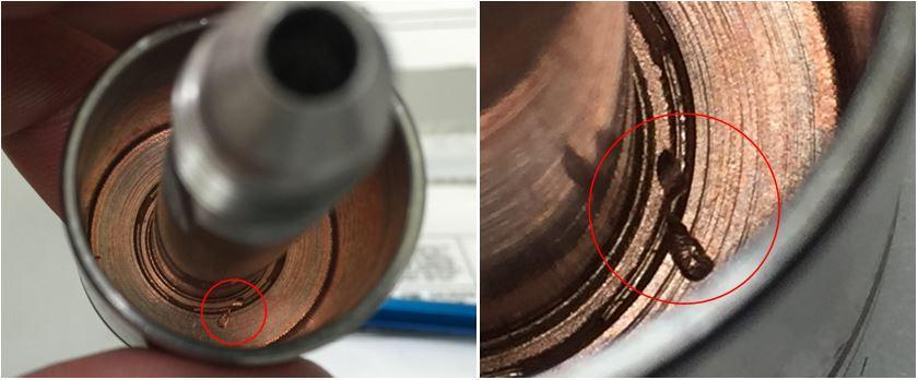
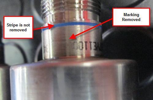
2 Thread Damage: Threads shall be free from flaws that would affect run-on torque with a free running mating thread. Flaws which result in incomplete thread are acceptable providing they are not so deep as to cross the pitch line of the thread. There should be no more than three imperfections per unit length equal to thread O.D. Void: A gap or air bubble in a molded material resulting in loss of structural integrity. 2.0 REQUIREMENTS (ACCEPTANCE INSTRUCTIONS) The following is an overview of the defects which may or may not be acceptable based on the requirements of G.W. Lisk and their customers. 2.1 Internal Feature (Cannot be seen on full assembly): The following features (Chatter/Chatter Marks, Ding/Dent, Gouge, Nick, Scratch) are acceptable as long as: There is no raised material The flaw does not impact other features The flaw does not create a thin wall condition The flaw is not on a sealing surface The surface continues to meet surface finish requirement Above flaws are NOT ACCEPTABLE if they are on a sealing surface. All other listed flaws (Burr, Pinched, Pitting, Raised Material) are NOT ACCEPTABLE. 2.2 External Feature (Seen by G.W. Lisk Customer): The following features (Chatter/Chatter Marks, Ding/Dent, Gouge, Thread defects, Damage, Burr) are unacceptable, with the following specifications or exceptions: Chatter/Chatter Marks: Acceptable on a non-sealing surface provided it does not violate the surface finish requirements. Thread Damage: Reference EPS-805-S for burrs on threads. Threads shall be free from flaws that would affect run-on torque with a free running mating thread. Nicks and other flaws which result in incomplete thread are acceptable providing they are not so deep as to cross the pitch line of the thread, and providing there are no more than three imperfections per unit length equal to thread O.D. Shrink Sleeve Damage: There shall be no splits, cracks in the sleeving which would expose the lead wires. Wire Damage: An area on the insulation of a wire that has been reduced by either a gouge or dent is unacceptable as gouges or dents can affect the insulating properties of the wire. Damage to lead wires is unacceptable. (Figure 1.9.4) Molding Defects: (voids, short shot, flow lines, flash) are not acceptable on rubber or plastic parts. (Figure and 1.9.3) 2.3 Additional Defect Information Connectors: The connector marking shall remain in the same condition as received from the supplier. There shall be no loss of marking information or circular (red/blue) stripe around the circumference of the connector. (Figure 1.9.3) Lockwiring: The lockwiring shall have positive pull, correct twists per inch, pulled tight, and correct pigtail length. The lockwiring shall conform to the requirements of AS567 and NASM Plating: The plating shall be uniform in appearance and shall be free of pits, roughness, cracks, and nodules and show no signs of lack of adhesion such as; flaking peeling or blistering. The coating shall not be stained or discolored. However, staining as a result of rinsing or slight discoloration as a result of drying or baking is not cause for rejection. Refer to the specific EPS-500 series document called out on the drawing for workmanship criteria. (Figure and 1.7.2) Screws: Screws shall be flush to the surface and must have no gap between the head of the screw and mating part. Use of a feeler gauge is required if there is a visible gap between the head of the screw and surface of the part. There shall be no gap greater than.003. (Figure 1.9.6) Epoxy Workmanship: There shall be no excess epoxy exposed from the assembly. This is considered FOD and is not acceptable. (Figure 1.9.7) Please see below examples as referenced in definitions. Additional undefined and unacceptable defects are provided in the examples or can be requested from a quality engineer. 3.0 PACKAGING NOTIFICATION: External Suppliers are responsible for packaging material in order to best protect parts from these defects. If there are questions or concerns regarding appropriate packaging, suppliers should contact their SQE. Internal operations are responsible for appropriately packaging materials to move between operations. If there are questions or concerns regarding operation to operation packaging, the QE should be contacted.


3 Figure Example of Cracked Material Figure Examples of Unacceptable Burrs

4 Figure Examples of Unacceptable Burrs


5 Figure Examples of Dings/Dents Figure Example of Unacceptable Chatter

6 Figure Damage, Dings, and Scratches

7 Figure 1.6.1

8 Figure Casting Defects


9 Figure Damage to Plating Figure Examples of Unacceptable Plating Adhesion from Tape Test


10 Figure Figure Example of Unacceptable Surface Figure Examples of Pitting


11 Figure Example of a Flow Line Figure Examples of Voids Figure Examples of Process Defects


12 Figure Unacceptable Wire Damage


13 Figure Internal, Assembly Only Figure Unacceptable Screw Condition Figure Unacceptable Epoxy
EXTERNAL FEATURE: Feature on the part being delivered to a Lisk customer which is visible without disassembly.
 1.0 Purpose: 1.1 This procedure establishes the Engineering, Manufacturing and Quality definitions, requirements, and inspection criteria for workmanship of machined parts and assemblies. This standard
PAGE 12 : THREAD MEASUREMENT TECHNIQUE (Plated and unplated thread gauges)
") 40-60 Delaware St. MACHINING Part No. PR301 - INDEX- MACHINING SECTION Revision: 01/12/2012 PAGE 1 This Quality Standard applies to all metallic parts unless otherwise specified by drawing or specification.
40-60 Delaware St. MACHINING Part No. PR301 - INDEX- MACHINING SECTION Revision: 01/12/2012 PAGE 1 This Quality Standard applies to all metallic parts unless otherwise specified by drawing or specification.
ARTICLE 28 VISUAL EXAMINATION STANDARDS
 ARTICLE 28 VISUAL EXAMINATION STANDARDS Specification for Classifying Visual Defects in Glass-Reinforced Laminates and [ASTM D 2563-70 Parts Made Therefrom... 639 (1977)] 637 ARTICLE 28 VISUAL EXAMINATION
Manufacturing and Cosmetic Inspection Specification
 Document Reference: MISB-MACIS-Rev (1) Page 1 of 13 Manufacturing and Cosmetic Inspection Specification Revision Change History Rev No. Effective Date Affected Page Change Descriptions Prepared by Reviewed
Quality Assurance Supplier Reference Guide
 Quality Assurance Supplier Reference Guide Tel: (561) 840-1800 * Fax: (561) 844-8551 www.svmicrowave.com Table of Contents Page 1.0 Introduction 1 2.0 SV Drawing Format Interpretation 2 3.0 Inspection
MIL-STD-1580B REQUIREMENT 11 DETAILED REQUIREMENTS FOR CONNECTORS
 DETAILED REQUIREMENTS FOR CONNECTORS 11. General. This section describes detailed requirements for a DPA of commonly used connectors. These requirements supplement the general requirements in section 4.
Quality Assurance Supplier Reference Guide
 Quality Assurance Supplier Reference Guide Tel: (561) 840-1800 * Fax: (561) 844-8551 www.svmicrowave.com 7/20/2015 Table of Contents Page 1.0 Introduction 1 2.0 SV Drawing Format Interpretation 2 3.0 Inspection
REVISIONS. Do not reproduce or share without prior written approval of RAM Company Page 2 of 20 REV DATE BY CHANGE PAGES AFF.
 written approval of RAM Company Page 2 of 20 REVISIONS REV DATE BY CHANGE PAGES AFF. N/C 3/27/91 DMA Original release ALL A 12/21/16 HMF Reactivated this specification number from the cancelled original
YAZAKI SPECIFICATION YNA-IS-001
 YAZAKI SPECIFICATION YNA-IS-001 YNA Inspection Standard for Instrument Panel Cosmetic Components 1. General This Cosmetic Inspection Standard describes the inspection criteria and methodology of cosmetic
Inspection Method Sheet
 Inspection Method Sheet Part Number: Generic Part Name: PCB Filters Drawing Number: Generic Operation: In Process / Final Page 1 of 10 Written By: Myra Cope Doc. #: TT-PC-0378 Rev. 14 Date: 10-15-08 Applicable
Workmanship Standards
 Workmanship Standards Q-50 1 rev 11/30/04 1.0 PURPOSE The purpose of this document is to achieve uniformity in the quality and appearance of each product produced by ADTRAN and ADTRAN suppliers and subcontractors.
WORKMANSHIP MANUAL A A
 Revision Record (only the last 25 records are listed in this page. See Doc. History for more information): Rev. Description By Date 1 Update label specifications clarify visual inspection DCR#16458 M.A.
COSMETIC SPECIFICATIONS
 FINISHES COSMETIC SPECIFICATIONS Unless otherwise specified, dimensions of a part or thread to which finishes are applied such as plating, oxides, powder/wet paint coatings, or other similar finishes,
PAGE 4 : VISUAL AIDS OF WORKMANSHIP STANDARDS
 Quality Approval: Quality Standards ISSUE 2 KIreland 7/24/14 - INDEX- SPECIAL PRODUCTS SECTION Revision: 07/24/14 PAGE 1 This Quality Standard applies unless otherwise specified by drawing or specification.
BAE SYSTEMS PROPRIETARY
 DATE: 14 November 2016 This document contains PROPRIETARY INFORMATION of BAE SYSTEMS and is to be used only by the Party it has been provided to and only for the purpose for which it has been supplied.
SUPERSEDED REVISION. Reasons for reissue of this instruction sheet are provided in Section 7, REVISION SUMMARY.
 PRO BEAM Jr. EB cable plug connectors are designed to be installed onto jacketed fiber optic cable with KEVLAR strength members. The connector must be assembled using a cable plug connector shell kit,
MILITARY SPECIFICATION
 MIL-R-47196A(MI) 6 September 1977 SUPERSEDING MIL-R-46196(MI) 12 July 1974 MILITARY SPECIFICATION RIVETS, BUCK TYPE, PREPARATION FOR AND INSTALLATION OF This specification is approved for use by US Army
Manufacturing Workmanship Standards. KSO Rev 1
 Manufacturing Workmanship Standards KSO Rev 1 This document is a statement to the quality and workmanship by Kso Metalfab, Inc. The definitions, procedures, and responsibilities contained in this Workmanship
Quality Procedure QP159 General Requirements for Machined Parts
 1. PURPOSE 1.1. This procedure provides general product fabrication requirements. It also provides interpretation of certain requirements specified on product drawings, models, and electronic files. 2.
Wiring Repair WIRING REPAIR
 20-10-00 Wiring Repair WIRING REPAIR 1. GENERAL This section contains procedures applicable to the fabrication and repair of wire harness assemblies, cables, and wires. All wiring repairs of wire harness
Workmanship Standards Manual Mechanical Fabrication, Fasteners, & Finishes
 Workmanship Standards Manual Mechanical Fabrication, Fasteners, & Finishes Prototek Sheetmetal Fabrication, LLC 244 Burnham Intervale Rd Contoocook, NH 03229 Section V -- Mechanical Fabrication, Fasteners,
SUBSTRATE APPEARANCE STANDARD
 1. PURPOSE The purpose of this standard is to describe appearance requirements for components that will be painted. These requirements, with regard to appearance attributes and blemishes, are outlined
Specification for Threading, Gauging and Thread Inspection of Casing, Tubing, and Line Pipe Threads
 Standard. It shall not be reproduced or circulated or quoted, in whole or in part, outside of API committee activities except with the approval of the Chairman of the committee having jurisdiction and
- Flash. A very thin gage, sometimes film-like material, which extends from the parting line projection, shall be removed.
 SEALING ELEMENTS 15. Tolerances and Surface Imperfections Size tolerances and surface imperfections on O-rings are influenced by the tolerance, finish, and cleanliness of the mold cavities from which they
Downloaded From JFETC.COM Sat, 21 Apr :39: * valid at time of download *
 FOX-TP-M-101 FILD INSPCTION OF FOX THRAD Downloaded From JFTC.COM January 2008 JF STL CORPORATION HUNTING OILFILD SRVICS INTRNATIONAL FOX-TP-M-101 Page-1 1. SCOP This describes the field inspection of
THROUGH-HOLE SOLDER JOINT WORKMANSHIP STANDARDS CLASS 2 TRAINING CERTIFICATION TEST (DVD-PTH-E) v.1
 v.1") This test consists of thirty multiple-choice questions. All questions are from the video: Through- Hole Solder Joint Workmanship Standards (DVD-PTH-E). Use the supplied Answer Sheet and circle the letter
This test consists of thirty multiple-choice questions. All questions are from the video: Through- Hole Solder Joint Workmanship Standards (DVD-PTH-E). Use the supplied Answer Sheet and circle the letter
Cosmetic Inspection Guidelines for Mechanical Components
 Table of Contents 1.0 Purpose/Scope/Timing... 2 1.1 Responsible Roles... 2 1.2 Communication... 2 1.3 Compliance Date... 2 2.0 Procedure/Quality Recd Requirements... 3 2.1 Global ppearance Guidelines...
NAVSEA STANDARD ITEM
 NAVSEA STANDARD ITEM FY-19 DATE: 01 OCT 2017 CATEGORY: I 1. SCOPE: 1.1 Title: Threaded Fastener Requirements; accomplish 2. REFERENCES: 2.1 Standard Items 2.2 S9086-CJ-STM-010/075, Fasteners 3. REQUIREMENTS:
Workmanship Manual A AH. Revision Record (only the last 25 records are listed in this page. See Doc. History for more information):
:") Revision Record (only the last 25 records are listed in this page. See Doc. History for more information): Rev. Description By Date Checked L Inc. DCR L C. B. 9/23/98 M Inc. DCR M C.B. 9/5/00 Bruce Scharf
Revision Record (only the last 25 records are listed in this page. See Doc. History for more information): Rev. Description By Date Checked L Inc. DCR L C. B. 9/23/98 M Inc. DCR M C.B. 9/5/00 Bruce Scharf
SYGEF Standard SYGEF Plus PVDF Flanges
 Installation Instructions 2009 Volume, Rev 02 PM451 SYGEF Standard SYGEF Plus PVDF Flanges Please read all instructions before attempting to install flanges. Introduction When to Use a Flange Flanges may
AFB (AIR FAN BEARING) INSTALLATION GUIDE
 INSTALLATION GUIDE") 654 AFB (AIR FAN BEARING) INSTALLATION GUIDE AFB PARTS Bearing Housing - Secured together with two 3/8 x 1.25 in. Cap Screws Black Wiper Seals - Secured together with O-ring cord (Subsequently depicted
654 AFB (AIR FAN BEARING) INSTALLATION GUIDE AFB PARTS Bearing Housing - Secured together with two 3/8 x 1.25 in. Cap Screws Black Wiper Seals - Secured together with O-ring cord (Subsequently depicted
Manufacturing Workmanship Standards Implemented November 2011
 Manufacturing Implemented November 2011 ~ 1 ~ This document is a statement to the quality and workmanship by York Haven Fabricators, Inc., henceforth referred to as YHF. The definitions, procedures, and
Sea Doo Spark Engine Access Kit
 Sea Doo Spark Engine Access Kit PART# - RS4-130-EAK APPLICATION(S): Sea Doo Spark. 2up & 3up Models. We strongly recommend the use of a service manual to familiarize yourself with the various components
WOOD WOOD
 12655 - WOOD 12655-1 Part One - General WOOD 1.0 All materials used in the finishing shall be of the highest grade of their respective kinds. Materials shall be evenly and smoothly applied by skilled mechanics.
Specification
 Specification 2018-04 Class: Test Instruction, Conditions of delivery Class No.:61 Technical conditions of delivery for elastomer parts JED 220 Previous Edition Part name (for databases) 2015-06 Elastomer,
Manufacturing Workmanship Standards YHF-WS Rev 2
 Manufacturing YHF-WS Rev 2 Approved by & date: 02/25/16 Approved by & date: 02/25/16 This document is a statement to the quality and workmanship of York Haven Fabricators, Inc., henceforth referred to
Downloaded From JFETC.COM Fri, 27 Apr :37: * valid at time of download *
 JFBAR-TP-M-101 (RV.3) FILD INSPCTION OF JFBAR THRAD Downloaded From JFTC.COM JUN 2017 JF STL CORPORATION JFBAR-TP-M-101 (RV.3) Page-1 1 SCOP This procedure describes the field inspection for JFBAR. 2 PIN
UNSIGNED HARDCOPY NOT CONTROLLED
 SUBJECT: APPROVED BY STATUS PURPOSE AFFECTED FUNCTIONS REFERENCES DEFINITIONS Painting Manager, Hardware Engineering Maintenance Revision Establish painting and inspection requirements for organic finishes
IX. FLARED JOINTS IX. FLARED JOINTS
 IX. FLARED JOINTS IX. FLARED JOINTS While copper tube is usually joined by soldering or brazing, there are times when a mechanical joint may be required or preferred. Flared fittings (Figures 28 and 29)
Visual Testing of Pipe Threads
 From NDT Technician, Vol. 10, No. 1, pp: 1 5. Copyright 2011 The American Society for Nondestructive Testing, Inc. The American Society for Nondestructive Testing www.asnt.org FOCUS AAs an oil well is
To define minimum workmanship standards for cartons and related items produced by Warneke Paper Box Company.
 Page 1 of 5 1.0 PURPOSE 2.0 SCOPE To define minimum workmanship standards for cartons and related items produced by Warneke Paper Box Company. Applies to all items produced by Warneke Paper Box Company.
FLEXIAL QUALITY PROCEDURE
 FLEXIAL QUALITY PROCEDURE QP159 Change History: See DCN for Details Rev Change DCN Number Date Initial Release A 08/12/04 DCN03633 B 9/30/13 DCN10841 C 1/20/2015 DCN12541 D 4/7/2015 DCN12791 Current Revision
Sealing Elements. Technical Handbook O-rings. 15. Tolerances and Surface Imperfections
 15. Tolerances and Surface Imperfections Size tolerances and surface imperfections on O-rings are influenced by the tolerance, finish, and cleanliness of the mold cavities from which they are produced.
I-W07/W77. Couplings DETAIL A WARNING. Photo Showing Pipe with Weld Seam Ground 6 inches/152 mm Back from Pipe End and an AGS Groove
 WARNING Read and understand all instructions before attempting to install any Victaulic piping products. These products must be used only on pipe that is prepared to Victaulic Advanced Groove System (AGS)
FAA APPROVED AIRPLANE MAINTENANCE MANUAL SUPPLEMENT. Eyebrow Window Replacement
 FAA APPROVED AIRPLANE MAINTENANCE MANUAL SUPPLEMENT AIRPLANE MAKE: Boeing AIRPLANE MODEL: 737-100, -200, -200C, -300, -400, -500, -600, -700, -700C, -800, -900 TO BE ADDED TO AMM CHAPTER 56-11-XX This
[QUALITY MANAGEMENT SYSTEM - GLASS STANDARDS] 1.0 Scope
![[QUALITY MANAGEMENT SYSTEM - GLASS STANDARDS] 1.0 Scope](/thumbs/75/71913237.jpg "[QUALITY MANAGEMENT SYSTEM - GLASS STANDARDS] 1.0 Scope") 1.0 Scope 1.1 This document defines the methods and quality criteria in which AMI establishes a common basis for inspection that exceeds the industry s and major manufacturers standards (ASTM C1036 Reference
1.0 Scope 1.1 This document defines the methods and quality criteria in which AMI establishes a common basis for inspection that exceeds the industry s and major manufacturers standards (ASTM C1036 Reference
Termination Procedure
 Connector Piece Parts Contact/Connector Head Twist On Nut MX MX Boot Procedure Chart Procedure Tool Required Tool Part Number Cable Preparation & Fiber Cleaning Jacket Stripper 86710-0004 Cable Preparation
Catalog October Speedi-Sleeve The quickest and most economical way to repair worn shafts
 Catalog 457027 October 2005 Speedi-Sleeve The quickest and most economical way to repair worn shafts Table of Contents The Speedi-Sleeve concept...3 SPEEDI-SLEEVE, the quickest and most sensible way to
Do-it-yourself plastic repair kit by Jaeger Aviation
 Do-it-yourself plastic repair kit by Jaeger Aviation If your aircraft is adorned by yellowed, cracked and broken window trim, side panels or headliner there is something you can do about it! In the past,
Through-Hole Solder Joint Evaluation
 Through-Hole Solder Joint Evaluation Training & Reference Guide IPC-DRM-PTH-G Association Connecting Electronics Industries IPC-A-610 Rev. G OCT 2017 Table of Contents Dimensional Criteria Solder Destination
Rigid Fluid Lines Tubing Materials Material Identification 7-1
 Aircraft fluid lines are usually made of metal tubing or flexible hose. Metal tubing (also called rigid fluid lines) is used in stationary applications and where long, relatively straight runs are possible.
METAL FABRICATION SECTION 8: METAL FABRICATION SCOPE MATERIAL.
 METAL FABRICATION SCOPE This specification applies to all metal intended to be rubber lined. Metals furnished must conform to this specification with respect to suitability for rubber lining or covering.
Dicing Through Hard and Brittle Materials in the Micro Electronic Industry By Gideon Levinson, Dicing Tools Product Manager
 Dicing Through Hard and Brittle Materials in the Micro Electronic Industry By Gideon Levinson, Dicing Tools Product Manager A high percentage of micro electronics dicing applications require dicing completely
Metal & Vinyl, Flush Mount and Recessed Fin Windows Recommended Installation Instructions
 PO Box 480 Ph: 417-235-7821 Monett, MO 65708 Fax: 417-737-7140 Metal & Vinyl, Flush Mount and Recessed Fin Windows Recommended Installation Instructions These installation instructions are recommendations
3 Emergency Breakaway Coupling
 SM64227 July 2008 Applicable addition manuals: N/A Aerospace Group Conveyance Systems Division Carter Ground Fueling Maintenance & Repair Manual 3 Emergency Breakaway Coupling Model 64227 Table of Contents
Technical Specification TS ZSO 003 c. Reconditioning Service-Quality criteria: Technical condition framed panels
 Page: 1 / 10 1 Description Description of all relevant quality criteria for frame formwork elements. The Reconditioning Service-Quality criteria are simplified summaries of the Reconditioning Service working
INSTALLATION MANUAL FOR STAINLESS STEEL, GROOVE-END, FLEXIBLE COUPLINGS
 PIEDMONT PACIFIC CORPORATION INSTALLATION MANUAL FOR STAINLESS STEEL, GROOVE-END, FLEXIBLE COUPLINGS 4703 Tidewater Ave., Suite G Oakland. CA, 94601, USA Ph: +1 510 434 0990 / Fax: +1 510 436 0990 www.piedmontpacific.com
Manufacturing Sun Cartridge Cavities
 Manufacturing Sun Cartridge Cavities The following Technical Tip discusses a variety of points that should be considered when manufacturing a Sun cavity. Many of the items discussed could be classified
For board-to-fpc. Narrow pitch connectors (0.4mm pitch)
") Automation Controls Catalog For board-to-fpc Narrow pitch connectors (0.4mm pitch) F4 Series 5.0mm 4.1mm RoHS compliant FEATURES 1. 0.9 mm mated height low profile two-piece type connectors 2. Strong resistance
Automation Controls Catalog For board-to-fpc Narrow pitch connectors (0.4mm pitch) F4 Series 5.0mm 4.1mm RoHS compliant FEATURES 1. 0.9 mm mated height low profile two-piece type connectors 2. Strong resistance
EastRising LCD Panel Quality Criteria
 EastRising Technology Co.,Ltd. EastRising LCD Panel Quality Criteria ISO9001 Registered Company sira CERTIFICATION 011 REV Descriptions Release Date 1.0 Preliminay Release Nov-24-2009 2.0 Add more Precaution
Read and understand the requirements of this procedure Assist students with installation as needed
 1. PROCEDURE OVERVIEW This procedure is to be used for installation of bonded strain gages on reinforcing bars. It includes necessary materials and a recommended practice for surface preparation, installation,
MATERIALS & TOOLS REQUIRED INTRODUCTION. Before you start turning, read and understand this entire procedure.
 INTRODUCTION This set of instructions shows one method to turn mills.there are many other possible variations and techniques. NOTE: These instructions are specific to 'Chef Specialties' mechanism. For
REVISION LIST CHAPTER 25: AFT WINDOWS. The following list of revisions will allow you to update the Legacy construction manual chapter listed above.
 REVISION LIST CHAPTER 25: The following list of revisions will allow you to update the Legacy construction manual chapter listed above. Under the Action column, R&R directs you to remove and replace the
UNSIGNED HARDCOPY NOT CONTROLLED
 Subject: APPROVED BY STATUS PURPOSE AFFECTED FUNCTIONS s Manager, Hardware Engineering Maintenance Revisioin Establishes requirements for the manufacture and inspection of pipe threads. L-3 Communications
D. Thermally Sprayed Metallic Coating (Flame Spray): STD SPEC
: STD SPEC") STANDARD SPECIFICATION SECTION 05121 MISCELLANEOUS METALWORK PART 1 - GENERAL 1.01 DESCRIPTION This section includes materials, fabrication, and installation of structural steel, connecting bolts, pipes,
STANDARD SPECIFICATION SECTION 05121 MISCELLANEOUS METALWORK PART 1 - GENERAL 1.01 DESCRIPTION This section includes materials, fabrication, and installation of structural steel, connecting bolts, pipes,
- INSTALLATION INSTRUCTIONS -
 . Supercharger Shaft Upgrade Kit PART# - RY17040-UK-6S5-2 APPLICATION(S): Yamaha FX-SHO, FZR & FZS Required tools Part# IN LB Electronic Torque Wrench N/A T-30 Torx Bit Socket N/A 3mm Allen Wrench N/A
Fortress Fe Posts must always be secured to the deck framing. Fortress Fe Posts should never be attached to only the deck boards.
 Installation Instructions for Fortress Horizontal Cable Panel System with UB-05 Brackets and Fe Posts It is the responsibility of the installer to meet all code and safety requirements, and to obtain all
Figure 1 Photograph of a strain gage on a helical wire
 1. PROCEDURE OVERVIEW This procedure is to be used for installation of bonded strain gages on prestressing strand. It includes necessary materials and a recommend practice for surface preparation, installation,
Installation and Specification Manual December 2012
 Installation and Specification Manual December 2012 APOLLOXPRESS TM fittings are a heat-free method for joining copper tube and provide a clean, easy to use joining method designed to save time and money
Machine Shop Processes
 Machine Shop Processes 100-1122-00 Owner 1 of 6 Approvals: Department Approved. Date Engineering D. Scott Timms 11/7/17 Manufacturing D. Scott Emond 11/7/17 Quality Andrew Ware 11/7/17 Change History Rev
Fuel - Defuel Valve. Model Maintenance & Repair Manual. SM61499 Issued: February 1996 Applicable additional manuals: NONE
 Aerospace Group Conveyance Systems Divison Carter Brand Ground Fueling Equipment SM61499 Issued: February 1996 Applicable additional manuals: NONE Maintenance & Repair Manual Fuel - Defuel Valve Model
Repair Instructions. Durametallic PSS III. Experience In Motion. Split Seal
 Repair Instructions Durametallic PSS III Split Seal Experience In Motion PSS III seal reference Gland Gland Gasket Split Joint gasket Coil Spring Seal Drive Sleeve Gasket Split Joint Gasket Rotating Face
DVD-PTH-C Through-Hole Solder Joint Workmanship Standards
 DVD-PTH-C Through-Hole Solder Joint Workmanship Standards Below is a copy of the narration for the DVD-PTH-C video presentation. The contents for this script were developed by a review group of industry
METAL METAL
 12654 - METAL 12654-1 PART ONE: GENERAL METAL 1.1 Architectural metals shall be of the best commercial quality and their various forms shall be straight and true. There shall be no scratches, scars or
PROPELLER SHAFT GROUP CONTENTS GENERAL INFORMATION SPECIAL TOOLS SERVICE SPECIFICATIONS PROPELLER SHAFT...
 25-1 GROUP 25 CONTENTS GENERAL INFORMATION........ 25-2 SERVICE SPECIFICATIONS....... 25-2 LUBRICANTS.................. 25-2 SEALANT...................... 25-2 SPECIAL TOOLS................ 25-2.............
CIRRUS AIRPLANE MAINTENANCE MANUAL
 FASTENER AND HARDWARE GENERAL REQUIREMENTS 1. DESCRIPTION This section contains general requirements for common hardware installation. Covered are selection and installation of cotter pins, installation
. Recommended guidelines for the field inspection of TenarisHydril connections, FSOG Wedge 513. Handling Plugs TN 9906.
 Wedge 513 / 511 Connections Scope These guidelines apply specifically to the use of Wedge 513 and Wedge 511 connections. This document should be used in conjunction with the Running Manual which is the
Assembly instructions
 Assembly instructions Important notes on VOSS assembly instructions In order to ensure maximum performance and functional reliability of VOSS products, the respective assembly instructions, operating conditions
1/6 PA-25 PAWNEE. *Specifications are subject to change without notice.*
 1/6 PA-25 PAWNEE INSTRUCTION MANUAL [ A335 Kit ] Wing Span : 72 in / 1830 mm Wing Area : 736 sq in / 47.5 sq dm Flying Weight : 6.6 lbs / 3000 g Fuselage Length : 48 in / 1220 mm Requires : "Glow Power"
HBS-AP ASSEMBLING INSTRUCTIONS
 ALUMINIUM PIPEWORK - ALUMINIUM PIPEWORK - ALUMINIUM PIPEWORK 97 HBS-AP ASSEMBLING INSTRUCTIONS 1. INTRODUCTION 1.1. This manual is very easy to consult and we recommend reading it before starting work,
Termination for M29504/4, /5, /6 & /7, Style 2 (Tight)
") Ξ XiOptics Optical fiber termination is a very process dependent operation. Consideration of the optical terminus, adhesive system and the optical cable/fiber must all be taken into consideration. XiOptics,
Ξ XiOptics Optical fiber termination is a very process dependent operation. Consideration of the optical terminus, adhesive system and the optical cable/fiber must all be taken into consideration. XiOptics,
TEST PROCEDURE FOR DYNAMIC PULL-THROUGH PERFORMANCE OF ROOFING MEMBRANES OVER FASTENER HEADS OR FASTENERS WITH METAL BEARING PLATES
 TESTING APPLICATION STANDARD (TAS) 117(B)-95 TEST PROCEDURE FOR DYNAMIC PULL-THROUGH PERFORMANCE OF ROOFING MEMBRANES OVER FASTENER HEADS OR FASTENERS WITH METAL BEARING PLATES 1. Scope 1.1 This Protocol
API Buttress Connections
 IDM Code GDL00382/2 / March 2018 API Buttress Connections Scope These guidelines apply specifically to the use of API Buttress connections. This document is based on API 5C1 standard which is the main
Section 914. JOINT AND WATERPROOFING MATERIALS
 914.01 Section 914. JOINT AND WATERPROOFING MATERIALS 914.01. General Requirements. Joint and waterproofing material for use in concrete construction must meet the requirements of this section. 914.02.
It s been said before, and we ll say it
 Wood NOFMA Tip Sheet by MICKEY MOORE Trouble with Refinishing a Wood Floor It s been said before, and we ll say it again; It all begins with customer expectations. What the customer expects the final product
Customer Manual
 03APR2013 Rev. F 1. PRODUCT NAME AND MODEL NUMBER This product is called the Mini Multi Lock Connector (temporary name), which consists of the components shown in Tables 1 and 2. 1.1 Housing Model No.
Installation Instructions
 www.marlite.com Effective Date 03/01/2018 ARTIZAN FRP, SYMMETRIX FRP, ENVUE FRP, STANDARD FRP Installation Instructions Statements expressed in this technical bulletin are recommendations for the application
ProLine PL60 HEAVY FRAMELESS BYPASS BATH ENCLOSURE
 INSTALLATION INSTRUCTIONS ProLine PL60 HEAVY FRAMELESS BYPASS BATH ENCLOSURE Copyright Alumax Bath Enclosures 2013. All rights reserved. G03980847 5-1-13 !WARNINGS! INSTALLATION WARNINGS a) Alumax Bath
EXPENDABLES: Hook Fastener Tape, 2 in, P/N: A-A-55126, CAGE: 58536, NIIN: , (McMurdo PLB s only)
") 1 406 PLB INSP/ACCEPT REFERENCES: NONE TOOLS/TEST EQUIPMENT: NONE EXPENDABLES: Hook Fastener Tape, 2 in, P/N: A-A-55126, CAGE: 58536, NIIN: 010331734, (McMurdo PLB s only) CONSUMABLES: Marker, Paint, P/N:
1 406 PLB INSP/ACCEPT REFERENCES: NONE TOOLS/TEST EQUIPMENT: NONE EXPENDABLES: Hook Fastener Tape, 2 in, P/N: A-A-55126, CAGE: 58536, NIIN: 010331734, (McMurdo PLB s only) CONSUMABLES: Marker, Paint, P/N:
SPECIFICATIONS FOR 3M TM PRESTIGE SUN CONTROL WINDOW FILMS
 SPECIFICATIONS FOR 3M TM PRESTIGE SUN CONTROL WINDOW FILMS 1.0 Scope This specification is for an abrasion resistant solar control window film which when applied to the interior window surface will reduce
Troubleshooting Conventional Burnout Phosphate Bonded Investments
 Troubleshooting Conventional Burnout Phosphate Bonded Investments Phosphate investments are affected by many variables, but the following generalizations can be made: Thorough mixing insures complete reaction
Block and Ball Inspection Checklist
 Block and Ball Inspection Checklist 01/16 P/N 67688 Rev. 1 Page 2 of 8 Block and Ball Inspection Checklist The purpose for the inspection check list is to provide a quick reference for checking the integrity
INSTRUCTIONS FOR AIRFLEX 36WCBEP/36WCSEP WEAR PLATE REPLACEMENT USING GASKET SEALING TAPE
 INSTRUCTIONS FOR AIRFLEX 36WCBEP/36WCSEP WEAR PLATE REPLACEMENT USING GASKET SEALING TAPE The material included in this kit is to be used for WC styles of brakes that are designed or upgraded to the EP
VANITY INSTALLATION INSTRUCTIONS
 VANITY INSTALLATION INSTRUCTIONS Congratulations and thank you for your purchase. These cabinets have been designed and assembled to a very high standard and if installed correctly will provide you with
INSTALLATION MANUAL Sluice Gates, Stop-logs & Screens
 INSTALLATION MANUAL Sluice Gates, Stop-logs & Screens INTRODUCTION During manufacture and assembly of equipment great care is taken to ensure accuracy in mating the sealing faces on frame and doors, especially
3Insert the second rod no. 4
 Yamato: Step-by-step 37 The stern block and searchlight control towers a b c d e f Recommended tools and materials Wood glue Sandpaper (no. 800 grain) Metal file Putty Craft knife For metal: Super Glue
Kestrel Aluminium Systems Limited. Product Manual Section 11 Thermal Framing System - Fabrication. Manual Version
 Limited Product Manual Section 11 - Fabrication Manual Version 23.0.1 Section 11.01 Fabrication 11.01.01 sheet 1 General guidelines for cutting and bar preparation Section 11 Contents Section 11.02 Fabrication
RIGHT ABRASIVE DETERMINING THE BEST ABRASIVE POST-PROCESSING WELD GRINDING STARTS BY UNDERSTANDING THE FAMILY OF ABRASIVE PRODUCTS.
 The RIGHT ABRASIVE DETERMINING THE BEST ABRASIVE by Terry Tupper, senior engineer, materials joining group, Fanuc FOR POST-PROCESSING WELD GRINDING STARTS BY UNDERSTANDING THE FAMILY OF ABRASIVE PRODUCTS
VISUAL INSPECTION GUIDE FOR ALL-RUBBER GLOVES EXCEPT SURGICAL
 SUPERSEDING MIL-STD-168A 31 December 1957 MILITARY STANDARD VISUAL INSPECTION GUIDE FOR ALL-RUBBER GLOVES EXCEPT SURGICAL FSC 8415 DEPARTMENT OF DEFENSE WASHINGTON, D. C. 20301 VISUAL INSPECTION GUIDE
ESCONDIDO FIRE DEPT TRAINING MANUAL Section Engine Module Page 1 of 9 Wildland Tool Maintenance Revised
 Engine Module Page 1 of 9 HANDTOOL CARE AND MAINTENANCE Hand tools must be sharp and stored in a clean, safe location and ready to use at all times. No hand tools may be carried in the same compartment