Lead from lead-based paints. Crystalline silica from bricks, cement, and other masonry products. Arsenic and chromium from chemically treated lumber.
|
|
|
- Ashlee Moody
- 5 years ago
- Views:
Transcription
1
2 Some dust created by power sanding, sawing, grinding, drilling, and other construction activities contains chemicals known to the State of California to cause cancer, birth defects or other reproductive harm. Some examples of these chemicals are: Lead from lead-based paints. Crystalline silica from bricks, cement, and other masonry products. Arsenic and chromium from chemically treated lumber. Your risk from these exposures varies, depending on how often you do this type of work. To reduce your exposure to these chemicals: work in a well ventilated area, and work with approved safety equipment, such as those dust masks that are specially designed to filter out microscopic particles.
3 Woodstock Technical Support... 3 About Your New 13½" x 40" Gear Head Lathe... 3 Machine Specifications... 4 Standard Safety Instructions... 6 Additional Safety Instructions for Metal Lathes... 8 Avoiding Potential Injuries V Operation Extension Cords Grounding Unpacking Items Needed for Set Up Inventory Cleaning Machine Machine Placement Handwheel Handles Mounting to Shop Floor General Turning On Power Three-Jaw Direct Mount Scroll Chuck Reversing Jaws Four-Jaw Direct Mount Independent Chuck Faceplate Tailstock Cutting Shallow Tapers with Tailstock Tailstock Alignment Centers Steady Rest Follow Rest Setting Compound Slide Four-Way Tool Post Gap Removal Manual Feed Setting RPM Start Up and Spindle Break-in Procedures Power Feed Setting Feedrate Thread Settings Changing Gears for Metric Threads Threading Operation... 35
4 General Cleaning Lubrication Maintenance Schedule Maintenance Notes General Cross Feed Backlash Gibs Replacing V-Belt Troubleshooting Gearbox Assembly Gearbox Breakdown Selector Lever Assembly Change Gear Assembly Gearbox Parts Gearbox Case Headstock Gear Breakdown Headstock Gear Breakdown Headstock Parts List Lathe Bed Lathe Bed Apron Assembly Apron Gears Thread Dial Assembly Apron Parts Carriage Assembly Cross Slide Assembly Carriage Parts Tailstock Assembly Tailstock Lock Assembly Tailstock Parts Follow and Steady Rest Assemblies Follow and Steady Rest Parts Stand Parts, Electrical, and Accessories... 69
5 We stand behind our machines! In the event that questions arise about your machine, parts are missing, or a defect is found, please contact Woodstock International Technical Support at (360) or send to:. Our knowledgeable staff will help you troubleshoot problems and send out parts for warranty. If you need the latest edition of this manual, you can download it from. If you still have questions after reading the latest manual, or if you have comments please contact us at: Your new 13½" x 40" Gear Head Lathe has been specially designed to provide many years of trouble-free service. Close attention to detail, ruggedly built parts and a rigid quality control program assure safe and reliable operation. This Model M ½" x 40" Gear Head Lathe has 8 speed settings 78 RPM through 2100 RPM powered by a 2 HP motor and delivered through a precision gear head system. The combination of cast iron construction, quick-change gear box, flame-hardened headstock gears, and precision-ground induction hardened bedways provide a solid lathe for any machinist. The Model M1019 also comes with a 6" 3-jaw chuck, an 8" 4-jaw chuck, a 4-way turret tool post, plus steady and follow rests. The Model M1019 also includes a 12" faceplate, and MT#3 live and dead centers. Woodstock International, Inc. is committed to customer satisfaction in providing this manual. It is our intent to make sure all the information necessary for safety, ease of assembly, practical use and durability of this product is included. -3-
6 Design Type... Floor Model Gear Head Lathe Type... TEFC Capacitor Start Induction Horsepower... 2 HP Phase/Voltage... Single-Phase, 220V Amps...12A Cycle and RPM...60Hz/1725 RPM Power Transfer... V-Belt Drive Overall Dimensions...71½"L X 26"D X 52½"H Height of Center Line... 45½" Footprint... 71" x 22" Lathe Weight (Shipping) lbs. Lathe Weight (Net) lbs. Swing Over Bed... 13½" Swing Over Gap... 19" Swing Over Saddle...8" Distance Between Centers... 40" Spindle Bore " Spindle Nose...D1 4 Cam-Lock Spindle Nose Taper... #5 Morse Taper Carriage Travel... 35" Cross Slide Travel... 6¼" Compound Slide Travel " Maximum Tool Size... ½" x ½" Lead Screw " x 8 TPI Longitudinal Feedrate Range " " Inches/Rev Cross Feedrate Range " " Inches/Rev Tailstock Barrel Taper... #3 Morse Taper Tailstock Barrel Travel... 3½" 8 Spindle Speeds... 78, 128, 210, 330, 510, 830, 1360, 2100 RPM Thread Range TPI Thread Range Metric mm Stand, Headstock, and Body... Cast Iron Bed Ways...Induction Hardened Head Stock Gears...Flame Hardened... 6" 3-Jaw Chuck with 2-Piece Jaws & an 8" 4-Jaw Chuck... 12" Faceplate... Steady Rest & Follow Rest... 4-Way Turret Tool Post...MT#3 Live Center & Two MT#3 Dead Centers -4-

7 Please take time to become familiar with the location of the controls and features on this machine. These controls and features will be mentioned throughout the manual and knowing them is essential to understanding the instructions, safety, and operations described in this manual.. Headstock Spindle Speed Selection Levers Power Indicator Light Emergency Stop Switch Jog Button Spindle Three-Jaw Chuck Steady Rest Four-Way Tool Post Compound Slide Backsplash Cross Slide Carriage Live Center Quill Quill Lock Tailstock Tailstock Handwheel Bed Ways Lead Screw Feed Rod Spindle FORWARD/REVERSE Rod Thread Dial Spindle FORWARD/REVERSE Lever Half-Nut Lever Feed Selector Lever Carriage Apron Cross Feed Handwheel Longitudinal Feed Handwheel Feed/Lead Selector Knob Feed Speed Selection Levers Feed Direction Selector -5-
8 Learn the applications, limitations and potential hazards of this machine. Keep the manual in a safe and convenient place for future reference. Clutter and inadequate lighting invite potential hazards. If a machine is equipped with a three-prong plug, it must be plugged into a threehole grounded electrical receptacle or grounded extension cord. If using an adapter to aid in accommodating a two-hole receptacle, ground using a screw to a known ground. Use safety glasses with side shields or safety goggles that meet the appropriate standards of the American National Standards Institute (ANSI). Do not operate this machine in wet or open flame environments. Airborne dust particles could cause an explosion and severe fire hazard. and in working condition. before connecting power to machine. free of clutter, grease, etc. Indicates an imminently hazardous situation which, if not avoided, WILL result in death or serious injury. Indicates a potentially hazardous situation which, if not avoided, COULD result in death or serious injury. Indicates a potentially hazardous situation which, if not avoided, MAY result in minor or moderate injury. This symbol is used to alert the user to useful information about proper operation of the equipment, and/or a situation that may cause damage to the machinery. Visitors must be kept at a safe distance while operating unit. with padlocks, master switches or by removing starter keys. -6-
9 The machine will do a safer and better job at the rate for which it was designed. Do not force machine or attachment to do a job for which it was not designed. Do not wear loose clothing, neck ties, gloves, jewelry, and secure long hair away from moving parts. Before turning the machine on, make it a habit to check that all chuck keys and wrenches have been removed. But if you must use one, examine the extension cord to ensure it is in good condition. Immediately replace a damaged extension cord. Always use an extension cord that uses a ground pin and connected ground wire. Use an extension cord that meets the amp rating on the motor nameplate. If the motor is dual voltage, be sure to use the amp rating for the voltage you will be using. If you use an extension cord with an undersized gauge or one that is too long, excessive heat will be generated within the circuit, increasing the chance of a fire or damage to the circuit. at all times.. Wait until it comes to a complete stop before leaving the area. Follow lubrication and accessory attachment instructions in the manual. Operating machines near pilot lights or open flames creates a high risk if dust is dispersed in the area. Dust particles and an ignition source may cause an explosion. Do not operate the machine in high-risk areas, including but not limited to, those mentioned above. difficulties performing the intended operation, stop using the machine! Then contact our technical support or ask a qualified expert how the operation should be performed. Develop good habits in your shop and safety will become second-nature to you. in people and animals, especially when cutting fumes can be inhaled. Make sure you know what type of metal and cutting fluid you will be exposed to and how to avoid contamination. -7-
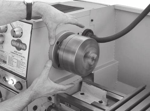
10 Always use a brush to clear chips. Never clear chips when the chuck is moving. Always select the right cutter for the job, and make sure it is sharp. The right tool decreases strain on the lathe components and provides a better finish. Always remove chuck key. Never let go of the chuck key while it is still in the chuck. Make sure workpiece is properly held in chuck before starting lathe. A workpiece thrown from the chuck may severely injure you or a bystander. Turn lathe and allow the spindle to completely stop before changing speeds. Large lathe chucks are very heavy and sometimes awkward to hold. Get assistance when installing large chucks. Protect your hands and the precision ground ways by using a chuck cradle or piece of plywood over the ways of the lathe when installing chucks. Make sure workpiece has adequate clearance before starting machine. Check tool and tool post clearance, and chuck and saddle clearance before starting the lathe. Always use the appropriate feed and speed rates. Using the correct speed increases operator control, which decreases the possibility of operator injury. Never attempt to slow or stop the lathe chuck by using your hand. Always shut the lathe before you leave it unattended. An unsupervised lathe that is running invites accidents. Tie up long hair or ponytails, and secure or remove loose clothing to avoid entanglement with moving parts. Make sure no part of the tool, tool holder, compound slide, cross slide, or carriage will contact the chuck during operation. Release automatic feeds after completing a job. Automatic feeds left engaged leave little time for an unsuspecting operator to avoid a "crash" after turning the lathe. -8-


11 Protecting the bed ways and working safely with electricity. Always wear safety glasses. Never use hands to stop spindle. Never take your hand off of the chuck key when inserted in spindle or chuck. -9-
12 The Model M1019 is prewired for 220 volt, single-phase operation. You will need a NEMA-style 6-15 plug and outlet (see ). The motor supplied with this gear head lathe is rated at 2 HP and will draw approximately 12 amps during 220 volt operation. For 220V operation, only connect your machine to a circuit that is protected by a 15 amp circuit breaker. Using a circuit breaker rated higher than 15 amps will increase the risk of fire! Keep in mind that a circuit being used by other machines or tools at the same time will add to the total load being applied to the circuit. Add up the load ratings of all machines on the circuit. If this number exceeds the rating of the circuit breaker or fuse, use a different circuit. We do not recommend using an extension cord for 220V equipment. Instead, arrange the placement of your machinery and installed wiring to eliminate the need for extension cords. If you must use an extension cord, please use the following guidelines: Typical 220V 15 Amp 3-prong plug and outlet. Use cords rated for Standard Service Never exceed a length of 50 feet Use cords with 12 ga. wire or bigger Ensure cord has a ground wire and pin Do not use cords in need of repair This machine must be grounded! The electrical cord supplied with this machine does not come with a 220 volt plug. Use a plug with a ground pin. If your outlet does not accommodate a ground pin, have it replaced by a qualified electrician or have an appropriate adapter installed and grounded properly. An adapter with a grounding wire does not guarantee the machine will be grounded. A ground source must be verified. -10-
13 The Model M1019 has been carefully packaged for safe transporting. If you notice the machine has been damaged, please contact your authorized dealer immediately. The following items are needed, but not included, to setup your machine: Fork Lift or other power lifting equipment Webbing Slings (Minimum of 1500 lb lifting capacity) Precision Level Safety Glasses (for each person) Solvent for cleaning Shop Rags for cleaning -11-
...1 Follow Rest (Not Shown)...1 Kick Plate and Support Brackets...1 12\" Faceplate...1 8\" Four-Jaw Universal Chuck with Key...1 Camlock Studs with Set Screws.")

14 The following is a description of the main components shipped with the Model M1019. Lay the components out to inventory them. A C Model M1019 Gear Head Lathe...1 Base (In their own boxes)...2 Steady Rest (Mounted on Lathe)...1 Follow Rest (Not Shown)...1 Kick Plate and Support Brackets " Faceplate...1 8" Four-Jaw Universal Chuck with Key...1 Camlock Studs with Set Screws...3 Chip Tray...1 Backsplash...1 B Main contents. E B Handwheel Handles...3 Oiler...1 Drill Chuck with Key B Live Center...1 Wrench for Tool Post with Handle...1 Large Chuck Key with Handle...1 Spindle Sleeve Adapter...1 Drill Chuck Arbor B16 X MT3...1 #3 Morse Taper Dead Centers...2 Phillips and Flat Head Screwdrivers...1 Ea Hex Wrenches 2.5, 3, 4, 5, 6, & 8 mm...1 Ea Open-End Wrenches... 9/11, 10/12, 12/14, & 17/19mm...1 Ea Chuck Key (3-jaw & spindle)...1 Gear, Metric Threading...1 Brass Dowel...2 Hardware Bag...1 Flat Washers 12mm...6 Hex Bolts M x Phillips Head Screws M6-1 x Lock Washers 6mm...4 Hex Nuts M If any parts appear to be missing, check the packaging to be sure the parts are not in the packing materials. If any parts are missing, find the part number in the back of this manual and contact Woodstock International, Inc. at (360) or at. H Loose items and small wooden box contents. J U K T G L S V M Tool box contents. I R Q N W P X F Y O -12-

15 The table and other unpainted parts of your lathe are coated with a waxy grease that protects them from corrosion during shipment. Clean this grease off with a solvent cleaner or citrus-based degreaser. DO NOT use chlorine-based solvents such as brake parts cleaner or acetone if you happen to splash some onto a painted surface, you will ruin the finish. Your lathe weighs 1261 lbs. distributed in a 71" x 22" footprint. We recommend placing this machine on concrete floors only. Consider existing and anticipated needs, size of material to be processed through the machine, and space for auxiliary stands, work tables or other machinery when establishing a location for your gear head lathe (see ). Minimum wall clearances. Lighting should be bright enough to eliminate shadow and prevent eye strain. Electrical circuits must be dedicated or large enough to handle amperage requirements. Outlets must be located near each machine, so power or extension cords are clear of high-traffic areas. Follow local electrical codes for proper installation of new lighting, outlets, or circuits. -13-


16 Remove the stands from their box and place them on the floor close to the final location of the lathe. Attach the kick plate brackets to the stand with the M6-1 x 10 Phillips head screws and attach the kick plate to the brackets with the remaining Phillips head screws and hex nuts. Place the chip tray on top of the stands. Line up the holes in the tray with the holes on top of the stands. Assembled lathe. Thread the slings behind all rods and around the bedway casting as shown in to avoid damaging the lead screw, feed rod, or ON/OFF rod. Move the carriage to adjust the lathe balance. Use a fork lift or an overhead crane to raise the lathe off of the crate and move it over the stands. Line up the holes in the base of the lathe with the stand holes and slowly lower the lathe into place. Thread M X 45 hex bolts with washers through the holes in the lathe, chip tray, and the stand. Attach the backsplash to the lathe using the fasteners already in the lathe. Move the lathe to its final location using the lifting method pictured in. Lifting method for lathe. Crossfeed Handwheel Using a screwdriver, thread the tailstock and longitudinal handles () into the handwheels. Thread the crossfeed handle into the handwheel and tighten with an 11mm wrench. Longitudinal Handwheel Longitudinal and crossfeed handle locations. -14-


17 Although not required, we recommend that you mount your new machine to the floor. Because this is an optional step and floor materials may vary, floor mounting hardware is not included. Generally, you can either bolt your machine to the floor or mount it on machine mounts. Both options are described below. Whichever option you choose, it will be necessary to level your machine with a precision level. Lag shield anchors with lag bolts () and anchor studs () are two popular methods for anchoring an object to a concrete floor. We suggest you research the many options and methods for mounting your machine and choose the best that fits your specific application. Typical lag shield anchor and lag bolt. Using machine mounts, shown in, gives the advantage of fast leveling and vibration reduction. The large size of the foot pads distributes the weight of the machine to reduce strain on the floor. Typical anchor stud. Machine mount example. -15-

18 The Model M1019 will perform many types of operations that are beyond the scope of this manual. Many of these operations can be dangerous or deadly if performed incorrectly. The instructions in this section are written with the understanding that the operator has the necessary knowledge and skills to operate this machine. If you are an inexperienced operator, we strongly recommend that you read books, trade articles, or seek training from an experienced lathe operator before performing any unfamiliar operations. Once plugged in, the lathe always has power. The green "Power" light shown in will be lit to indicate a live connection. If you depress the EMERGENCY STOP button, the power light will go out and cut power to machine operations only. Twisting the EMERGENCY STOP button clockwise and letting it pop out will restore power to machine operations. To cut power to the machine entirely, you will need to unplug or disconnect the lathe from the power source. Power Light Emergency Stop Power light and emergency stop locations. -16-

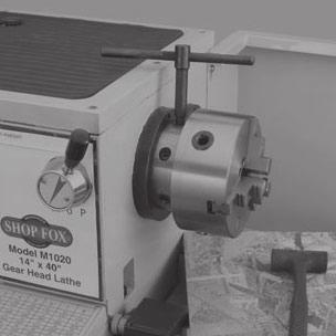
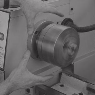
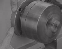
19 Three-jaw scroll chucks feature hardened steel jaws that self-center the workpiece within 0.002"-0.003". These jaws are reversible for chucking large diameter workpieces. The three-jaw direct mount scroll chuck featured in these instructions has three cam-lock studs that mount directly to the chuck and hold the chuck tight to the spindle nose. Chuck Key Dead Blow Hammer A Chuck Cradle or a piece of plywood large enough to span the bedways and support the weight of the chuck Breaker Bar (optional) Lay a chuck cradle or protective layer of plywood over the bedways to protect the precision ground surfaces from damage and to prevent fingers from being pinched (see ).. Loosen the 3 cam-locks by turning the chuck key counterclockwise until the mark on the cam-lock aligns with the single mark on the spindle nose in This will be approximately one-third of a turn. If you look carefully, you will see the cam-lock rise up out of the spindle nose. If the cam-lock stud does not freely release from the cam-lock, wiggle the cam-lock until the cam-lock stud releases. Simple chuck cradle made of scrap lumber. These cam-locks may be very tight. A breaker bar may be used to add leverage. Indicator arrows. -17-
. Spindle Nose Taper Installing and removing a small chuck.")


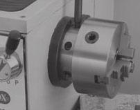
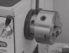
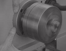
20 Using a dead blow hammer or other soft mallet, lightly tap around the outer circumference of the chuck body to break the chuck free from the camlocks and from the spindle nose taper. With a rocking motion, carefully remove the chuck from the spindle nose (see ). Spindle Nose Taper Installing and removing a small chuck. Lay a chuck cradle or protective layer of plywood over the bedways to protect the precision ground surfaces from damage and to prevent fingers from being pinched. If the three-jaw scroll chuck does not have the camlock studs assembled, screw the cam-lock studs into the chuck body. Using your calipers, measure the height of the camlock studs from the previously installed chuck (see ). Adjust the cam-lock studs in the three-jaw chuck to match the measurement from the previous chuck. Measuring height of cam-lock studs. Trial-and-error adjustment will be needed if you do not have a previous cam-lock stud to reference. Once the proper length is obtained, thread in the cap screws to lock the cam-lock studs into position. Lift the chuck, and insert the studs onto the spindle nose (see ). Tighten each cam-lock clockwise until you feel the cam-lock engage the cam-lock stud. Continue to turn until you can't turn any further. You will see the chuck body draw-up to the spindle nose. Ideally the cam-lock mark will fall between the two pointed arrows on the spindle nose (see ). Tightening the cam-locks. -18-


21 With the chuck key, open the jaws so the workpiece lays flat against the chuck face and jaw step, or fits in the through hole. For jaw and work holding options, see. Turn each jaw until it makes contact with the workpiece. Turn the chuck by hand to make sure you have even contact with all three jaws and the workpiece is centered. If the workpiece is off center, loosen the jaws and adjust the workpiece. If the workpiece is centered, tighten the jaws. Loading a workpiece. The three-jaw chuck on the Model M1019 comes with twopiece hardened-steel jaws. When in the outside configuration, the jaws are used to hold the workpiece from the outer diameter. The inside jaw configuration is for holding larger work from the inside diameter. The inside jaw configuration can also hold a workpiece from the outside when held in the central position (see ). Cap screws securing the 3-jaw chuck. Remove the cap screws shown in with an 8mm hex wrench, and remove the jaw. Reverse one jaw at a time to prevent mixing up the order. Rotate the jaw 180 and replace it as shown in. Reversing the chuck jaws. Replace the cap screws. Make sure the longer cap screw remains in the thicker part of the jaw. -19-

22 Four-jaw chucks feature hardened steel jaws that are adjusted independently. Each jaw can be removed from the chuck body and reversed. Independent jaw adjustment and re versal allows for a wide range of work holding versatility. The four-jaw direct mount independent chuck featured in these instructions mounts the same way as the three-jaw chuck. Refer to the three-jaw chuck instructions beginning on. With the chuck key, open each jaw so the workpiece will lay flat against the chuck face. Support the workpiece. Lock the tailstock and then turn the tailstock quill so the dead center makes contact with the center point of your workpiece. Turn each jaw until it just makes contact with the workpiece. Tighten each jaw in small increments. After you have adjusted the first jaw, continue tightening in opposing sequence (see &). Check frequently to make sure you have not wandered off your center point due to applying too much pressure to a single jaw. Centering workpiece. Jaw tightening sequence. -20-


23 After the workpiece is held in place, back the tailstock away and rotate the chuck by hand. The center point will move if the workpiece is out of center (see). Make fine adjustments by slightly loosening one jaw and tightening the opposing jaw until the workpiece is precisely aligned. Use a lower RPM when machining heavy eccentric workpieces. The faceplate is used to turn non-cylindrical parts and for off-center turning. Install the faceplate according to the instructions for three-jaw chucks found on. Properly held workpiece for offset machining at low RPM.. Support the workpiece and slide the dead center, installed in the tailstock, to the workpiece. Lock the tailstock and turn the tailstock quill so the dead center applies enough pressure to the center point of your workpiece to hold it in place. For more information refer to on Lock the tailstock quill when sufficient pressure is applied to hold the workpiece in place. Additional support may be needed, depending on the workpiece. Faceplate with properly clamped eccentric in four locations. Secure the workpiece with a minimum of three independent clamping devices (see ). Failure to follow this step may lead to deadly injury to yourself or bystanders. Take into account rotation and the cutting forces applied to the workpiece when clamping to the faceplate. Use a lower RPM when machining heavy eccentric workpieces. -21-


24 The tailstock () of the Model M1019 lathe can be used to support workpieces with the use of a live or dead center. It can drill or bore holes in the center of a part with a #3 tapered shank drill, or using a drill chuck fitted with a #3 taper and a drill. It can also be used for cutting shallow tapers by using the offset adjustment. Slide the tailstock to the desired position. Pull up on the tailstock lock handle to lock the tailstock in place. Quill Feed Tailstock Lock Quill Lock With the tailstock locked, push down the quill lock handle to unlock. Tailstock and quill lock handles in locked position. Turn the quill feed handle clockwise to feed/move the quill towards the spindle, or counterclockwise to move it away from the spindle. Pull up on the quill lock handle to lock the quill in place. With the tailstock locked, push down to unlock the quill lock handle. Turn the quill feed handle clockwise to extend the quill about one inch. Setting up tailstock for drilling. Insert tapered drill arbor (), or a tapered shank drill (), into the quill until the taper is firmly seated. The matching tapers hold the arbor. Turn the quill feed handle clockwise to feed the drill bit into the rotating workpiece. To remove the chuck taper, turn the quill feed handle counterclockwise until the chuck is pushed out from the tailstock taper. Tapered shank drill fitting into quill taper. -22-
.")

25 The tailstock can be offset to cut a shallow taper on a part. Lock the tailstock in position. Set Screw Loosen the set screw located on the end of the tailstock (see ). Alternately loosen and tighten the two side adjustment screws until desired offset is indicated on the offset scale (see ). Tighten the set screw located on the end of the tailstock to lock the setting. Tailstock off-set adjustments. To return the tailstock back to original position, repeat the process until the centered position is indicated on the scale. The tailstock on the Model M1019 is aligned at the factory with the headstock. We recommend that you take the time to ensure that the tailstock is aligned to your own desired tolerances. Using an engineer's precision level on the bedways, make sure the lathe is level side-to-side and frontto-back. If the lathe is not level, correct this condition before proceeding. Adjustment Screw Off-Set Scale Off-set scale. Get two pieces of steel round stock, 2.00" in diameter x 6.00" long. Center drill both ends of one piece of the round stock. Set it aside for use in Using the other piece of stock, make a dead center by turning a shoulder to make a shank. Flip the piece over in the chuck and turn a 60º point (see ) Continued on next page Tailstock centering dead center. -23-

26 As long as the dead center remains in the chuck, the point of your center will remain true to the spindle axis. Keep in mind that the point will have to be refinished whenever it is removed and returned to the chuck. For more information refer to on. Place the live center in the tailstock. Attach a lathe dog to the bar stock and mount it between centers (see ) Turn approximately 0.010" off the diameter. Measure the stock with a micrometer. If the stock is fat at the tailstock end, the tailstock needs to be moved toward the operator half the distance of the amount of the taper (see ). Checking tailstock alignment. Move tailstock in half the distance of the taper. If the stock is thinner at the tailstock end, the tailstock needs to be moved away from the operator half the distance of the amount of the taper (see ). Mount a dial indicator so the dial plunger is on the tailstock barrel before making adjustments to the tailstock. Refer to on for making adjustments to the tailstock center. Turn another 0.010" off of the diameter and check for a taper. Repeat this process as necessary until the desired amount of accuracy is achieved. Viewed From Above Tailstock adjustment option #1. Move tailstock out half the distance of the taper. Viewed From Above Tailstock adjustment option #

. Matching tapers provide the locking action. Inserting dead center. Move the tailstock into position and lock in place.")
27 The Model M1019 lathe is supplied with a live center, a HSS MT#3 dead center, and an MT#3 dead center that is carbide tipped. The supplied MT#5-#3 sleeve fits into the spindle taper to hold an MT#3 center. The dead center is used in the tailstock to support workpieces. When used in the tailstock, make sure to keep the dead center tip and workpiece lubricated. Feed the quill out about 1" so that the dead center can be inserted. Insert the dead center into the quill opening (see ). Matching tapers provide the locking action. Inserting dead center. Move the tailstock into position and lock in place. Feed the quill into the workpiece. Make sure there is a center drilled hole in the end of workpiece for the dead center. Lock the quill into place once the live center and the part rotate together. The quill may need to be adjusted during operation. To remove the dead center, retract the quill until the dead center pops free. The dead center can also be used in the spindle. The most common application is when using the faceplate (see ). Remove the chuck from the spindle. Typical faceplate and dead center setup. Install the dead center in the spindle sleeve. Install the sleeve into the spindle opening. Attach the faceplate to the spindle. When using the dead center in the spindle, use a lathe dog so that your part will rotate with the spindle and not spin on the dead center tip. -25-


28 The steady rest serves as a support for long shafts (l/d ratio of 3:1 or greater). The steady rest can be placed anywhere along the length of the part. Set Screws Place the steady rest on the lathe bedways so the triangular notch fits over the angled portion of the rear bedway. Loosen the three set screws so the finger position can be adjusted (see ). Loosen the knurled screw and open the steady rest so a workpiece can fit inside (see ). Steady rest adjustments. Position the steady rest where desired. Tighten the bolt at base of the steady rest to secure in place. Close the steady rest so that the workpiece is inside the fingers and tighten the knob. Set the fingers snug to the workpiece and secure by tightening the set screws. Fingers should be snug and allow rotational movement of the workpiece. Lubricate the finger tips with an anti-seize grease during operation. After prolonged use, the fingers will show wear. Either mill or file the tips for a new contact surface. The follow rest in is mounted on the saddle and follows the movement of the tool. It can be attached/removed by two cap screws located at the base of the follow rest. The follow rest requires only two fingers as the cutting tool acts as the third. The follow rest is used on long, slender parts to prevent flexing of the workpiece from the pressure of the cutting tool. Finger Adjustment Knobs Positioning workpiece in steady rest. The sliding fingers are set similar to those of the steady rest, free of play but not binding. Always lubricate during operation. Remove the follow rest from the saddle when not in use. After prolonged use, the fingers will need to be milled or filed to cleanup the contact surface. Follow rest attachment. -26-


29 The compound slide is used to cut tapers on parts or to set the proper infeed angle when threading. It may also be used to cut specific lengths longitudinally, when set parallel to the spindle axis. Compound Slide The compound slide handwheel has a graduated dial for precise inch feed increments. The base of the compound slide has a graduated scale for angular setup. Loosen the two hex nuts, one on each side of the compound slide (see ). Rotate the compound slide to the desired angular position. Use the scale at the base of the slide and the indicator marks on the carriage to set the position. Tighten the two hex nuts. Be sure to not overtighten, as you may strip threads. Compound slide set at an angle. Tool Post Bolts Hex Nuts The four-way tool post is mounted on top of the compound slide, and allows a maximum of four tools to be loaded simultaneously. The four-way tool post allows for quick indexing to new tools. This is accomplished by rotating the top handle counterclockwise and then rotating the tool post to the desired position. Rotate the top handle clockwise to lock the tool into position. Tool holder and tool post. Choose the desired cutting tool. Loosen the tool post bolts so that the cutting tool can fit underneath the tool post bolts. Use a minimum of two tool post bolts to hold down the cutting tool and tighten firmly (see ). Repeat for the three remaining openings, as needed. -27-

30 The Model M1019 comes equipped with a gap section below the spindle that can be removed for turning large diameter parts or when using a large diameter faceplate. Taper Pins The gap is installed, then ground, at the factory during lathe assembly for precise fit and alignment. Factors during the remaining assembly apply additional forces to the gap; therefore, replacing the gap to the original position will be very difficult. Find the two taper pin nuts located on the bed of the gap (see ). Lathe gap. Using an open-ended wrench, tighten the nut. This will cause the taper pin to release. Remove the taper pin and repeat for the second nut. Remove the four cap screws and tap the outside of the gap with a dead blow hammer to loosen, and remove the gap section. This section will review the individual controls on the carriage and provide descriptions of their uses (see ). The longitudinal handwheel moves the carriage left or right along the bed. This handwheel is used when setting up the machine or when manual control is desired during turning operations. Compound Slide Handwheel Cross Feed Handwheel The cross feed handwheel moves the top slide toward and away from the work. Turning the dial clockwise moves the slide toward the workpiece. Longitudinal Handwheel Carriage Controls. The compound slide handwheel controls the position of the cutting tool relative to the workpiece. The compound slide is adjustable for any angle within its range. Angle adjustment is controlled by cap screws on the base of the compound slide. -28-
31 Use the table in to determine the cutting speed required for the material of your workpiece. Determine the final diameter, in inches, for the cut you are about to take. For this step you will need to average out the diameters or work with the finish diameter for your calculations. Use the following formula to determine the needed RPM for your operation: With the calculated RPM, examine the spindle speed chart on the front of the headstock to find the closest match. In most cases the calculated RPM will be in between the available spindle RPMs and you will need to use your judgement about choosing a higher or lower spindle RPM. Workpiece Material Cutting Speed (sfm) Aluminum & alloys 300 Brass & Bronze 150 Copper 100 Cast Iron, soft 80 Cast Iron, hard 50 Mild Steel 90 Cast Steel 80 Alloy Steel, hard 40 Tool Steel 50 Stainless Steel 60 Titanium 50 Plastics Wood For carbide cutting tools, double the cutting speed. These values are a guideline only. Refer to the for more detailed information. Cutting speed table for HSS cutting tools. Make sure the spindle is completely stopped before proceeding.. Move the HIGH/LOW lever shown in to the appropriate setting for the RPM that you are selecting. Speed Selection Lever High/Low Lever. Move the speed selection lever to the desired RPM setting. You may need to rotate the spindle by hand to get the levers to properly engage. Spindle speed selectors. -29-

32 It is essential to closely follow the proper break-in procedures to ensure trouble free performance. Complete this process once you have familiarized yourself with all instructions in this manual. Check oil levels in headstock and apron. Follow all lubrication procedures highlighted in on of this manual. Make sure there are no obstructions around or underneath the spindle. Set the spindle speed to the lowest RPM, refer to section on Turn the spindle ON/OFF switch shown in to the right and up for clockwise spindle rotation, and to the right and down for counterclockwise rotation. Turn the lathe and let it run for a minimum of 10 minutes in the clockwise direction and another 10 minutes in the counterclockwise direction. Turn the lathe, change gears to the next highest RPM and repeat this step for each RPM setting. Spindle ON/OFF switch. -30-

33 The carriage has longitudinal and cross slide power feed capabilities. The carriage can feed right or left, and the cross slide can also feed in or out. Turn the spindle and wait until it comes to a complete stop before making any gear changes. Move the feed direction lever to the desired setting. The arrow above the screw thread icon indicates the direction of longitudinal feed. Cross feed directions are as follows: when the arrow points left, the cross feed is away from the spindle axis; when arrow points right, the cross feed is towards the spindle axis (see ). Feed direction selector. These instructions are valid with a counterclockwise rotation of the spindle. All directions reverse when spindle rotation is reversed. Set the Feed Rod/Lead Screw selector shown in to Feed Rod. Feed Rod Lead screw Push the power feed lever shown in to the left and up to engage the cross feed. Pull the power feed lever to the right and down to engage the longitudinal feed. Return the lever to the center position to disengage the power feed.. Feed Rod/Lead Screw Selector. Cross Feed Longitudinal Feed Cross/Longitudinal Feed Selector. -31-
34 Feedrate is determined by the machined material, the type of tooling used, and by the desired finish. Refer to the for further information. Letters Numbers Turn the spindle and wait until it comes to a complete stop before making any gear changes. Set the power feed as described on. Use the feedrate chart ( ) to determine the lever combination for the desired feedrate. The upper value in each cell of the feedrate chart is for the longitudinal feed. The lower value is for the cross feed. Feed Rod/Lead Screw Feedrate control levers. To set the lathe to the slowest cross feedrate of " per inch, locate on the chart. The lever combination on the chart is E and 8. Change the feedrate using the levers shown in. The left lever is for letters, and the right is for numbers. Pull the knob on the lever and rotate it down. Line up the lever with the desired character, rotate the lever up, and allow the pin to engage in the hole. You may need to rotate the chuck by hand or move the longitudinal handwheel to get levers and gears to engage Feedrate Chart in IPR. -32-

35 The Model M1019 lathe is capable of cutting inch threads without changing gears but metric threads require a gear change. This will be explained in the next sub-section. Letters Numbers Turn the spindle and wait until it comes to a complete stop before making any gear changes. Find the desired metric thread pitch from or the desired TPI for inch threads from. Work to the left and up to determine the correct lever settings.these charts are also on the front of the headstock. To cut 20 TPI thread, the handle combination would be C and 3. Move the Feed Rod/Lead Screw selector to the lead screw position and move the feed direction selector to the desired thread direction (see ). You may need to rotate the spindle by hand or move the apron for the gears to engage. Move the same levers used for feedrate to the appropriate letter/number setting by pulling the knob on the lever and rotating it down. Line up the lever with the desired character, rotate the lever up, and allow the pin to engage in the hole. 40T x 127T x 40T A / /2 5 3 / /2 7 B / C D E " Feed Rod/Lead Screw. Feedrate control levers.. Inch thread chart. (23T) 8 TPI 40T 127T 120T X 40T 30T 120T X 127T 40T mm (23T) 8 TPI Feed right to left to turn a right-handed thread. Feed left to right to turn a left-handed thread Left/right hand threads The thread pitch listed in the upper right of each cell corresponds to the gear combination on the right of the top of the chart. The thread pitch in the lower left of the cell corresponds to the gear combination on the left. Metric thread chart. -33-
.")
36 The gears can be reconfigured to machine metric threads by installing a 30T gear or rearranging the existing gears depending on the desired thread. A B Remove the end cover door to expose the gears. To set the gears in the 30T/127T X 120T/40T configuration, remove the hex nut and the slot head screw (Items A and C shown in ). C F Loosen the hex nuts, Items G & E, and the cap screw, Item F, shown in and drop the large gear set out of its mesh. E Remove the 40T gear, Item B in, and replace it with the 30T gear. Remove the 40T gear, Item D, turn it around, and put it back on the shaft. To set the gears in the 40T/127T X 120T/40T configuration, remove the slot head screw shown in, Item C. Loosen hex nuts, Items G & E, and the cap screw, Item F, shown in and drop the large gear set out of its mesh. G Gear change locations. D Remove the 40T gear, Item D, turn it around, and put it back on the shaft. Replace the fasteners that hold the gears in place. DO NOT overtighten. Overtightening will make them difficult to remove. Move the large gears until they mesh with the smaller gears. Make sure there is a backlash of 0.002" " between gears and tighten the cap screw and hex nut to hold the gears in place. Setting the gears too tight will cause excessive wear and noise, setting the gears too loose may cause slippage and possibly break gear teeth. Close the end cover door and connect the power. -34-
is engaged with the lead screw.")
37 Set the compound rest to the appropriate angle for the given thread you want to cut. For a Unified National Series (UNF) thread, this is 29º off of vertical to the spindle axis. Set the tool tip perpendicular to the workpiece and center it vertically. Half Nut Lever Thread Dial Make sure the thread dial ()is engaged with the lead screw. If not, use a hex wrench to loosen the screw and rotate the thread dial until the gear engages with the lead screw, then tighten the screw to hold the dial in place. Select the RPM you want to use. A slower RPM will give you more time to react, especially if threading over a short distance or threading up to a shoulder. Half nut and thread dial locations. Indicator Scale Examine the thread charts (inch or metric) and set the feedrate selectors as explained on. Turn the spindle to verify settings. Check to see that the lead screw is turning and verify that the carriage moves in the correct direction by engaging the half nut lever shown in. Once you are confident the settings are correct, disengage the half nut and turn the spindle. Examine the thread dial chart to determine which numbers on the thread dial will engage the half nut. To maintain accuracy and consistency, engage the half nut on the same mark on each pass. Failure to start on the same number each time may lead to cutting off the thread made in the previous pass. If cutting metric threads, you will not use the thread dial. Once the half nut is engaged, you must leave it engaged until the threads are complete. TPI Scale TPI Scale / or / or / or or / or / or or or Thread dial chart. -35-


38 Regular periodic maintenance on your Model M1019 will ensure its optimum performance. Make a habit of inspecting your machine each time you use it. Loose mounting bolts. Worn switch or safety features. Worn or damaged cords and plugs. Damaged V-belt. Any other condition that could hamper the safe operation of this machine. Make sure to disconnect the lathe before cleaning it. Clean your machine every day or more often as needed. Remove chips as they accumulate. Chips left on the machine soaked with water based coolant will invite oxidation and gummy residue to build up around moving parts. Preventative measures like this will help keep your lathe running smoothly. Always be safe and responsible with the use and disposal of cleaning products. The headstock and apron use SAE 20W or an ISO 68 nondetergent gear oil or an equivalent lubricant. The oil level should be kept at the indicator mark in the sight glasses, as shown in. After three months of operation, drain the oil completely and refill. After the initial complete oil change, change the headstock oil on an annual basis or more frequently if heavier machine use requires it. Headstock Oil Sight Glass Headstock Oil Drain Headstock oil sight, filler, and drain locations. Apron Oil Fill A Lubricate all ball fittings. Clean and wipe down lathe. Replace headstock and apron gear oil. Inspect V-Belt and replace if needed Apron Oil Sight Glass Apron oil sight, filler, and drain locations.

.")
. Carriage ball fittings. Lubricate three oil ports (see ). Lubricate two oil ports. One of the ports is on top of the longitudinal handwheel (see ).")
39 Ball fittings are responsible for the majority of the machine lubrication. To lubricate ball fittings, clean the outside of the ball fitting, depress the ball with the tip of the oil can nozzle and squirt a little oil inside the fitting. Wipe off the oil port before and after oiling to keep out contaminants. Oil the areas listed below with one to two shots of SAE 20W non-detergent oil or equivalent. Some areas may require fewer or more shots depending on use. These areas include:. Quick change gearbox cover. Remove end access panel and oil the gearbox input shaft (see ). F D Remove the gearbox cover plate as shown in and oil each recessed hole (five to six drops). E Lubricate two oil ports on apron top (see ). G C Lubricate three oil ports (see ). H Lubricate one oil port (see ). Carriage ball fittings. Lubricate three oil ports (see ). Lubricate two oil ports. One of the ports is on top of the longitudinal handwheel (see ). Lubricate one oil port (see ). I J Lubricate three oil ports (see ). Lubricate two oil ports (see ). Coat the chuck scroll and chuck jaw scroll teeth with #2 lithium grease. Apply a light film of 20W oil to the spindle camlocks and chuck body. DO NOT apply any lubrication to the clamping surfaces. Tailstock ball fittings. -37-
 734-3482 or send e-mail to.")

40 This section covers the most common service adjustments or procedures that may need to be made during the life of your machine. If you require additional machine service not included in this section, please contact Woodstock International Technical Support at (360) or send to. Backlash is the amount of play found in a lead screw. It can be found by turning the cross slide handwheel in one direction, and then turning the handwheel the other direction. When the cross slide begins to move, the backlash has been taken up. Cap Screw for Securing Leadscrew Feed the cross slide toward the operator until it reaches the end of its travel. Remove the cap screw that secures the cross slide leadscrew nut (see ). Rotate the cross slide handle to feed the leadscrew nut out from under the cross slide as shown in. Tighten the backlash adjustment cap screw shown in in small increments. Test after each adjustment until the backlash amount is acceptable. Cap screw for securing the leadscrew. Leadscrew Nut Avoid overtightening the backlash adjustment cap screw. Overtightening will cause excessive wear to the sliding block and lead screw. Feed the leadscrew nut back under the cross slide and replace the cap screw removed in. Backlash Adjustment Cap Screw Leadscrew nut. -38-

. Saddle gib adjustments.")

41 The saddle, cross feed, compound rest, and tailstock lock can all be adjusted on the Model M1019 lathe. When adjusting gibs, keep in mind that the goal of gib adjustment is to remove sloppiness without causing the slides to bind. Loose gibs may cause poor finishes on the workpiece and may cause undue wear on the slide. Over-tightening may cause premature wear on the slide, lead screw, and nut. Hold the set screws with a hex wrench and then loosen the four hex nuts found at the bottom rear of the cross slide. Back each hex nut off one full turn (see ). Saddle gib adjustments. Turn the set screws with a hex wrench until a slight resistance is felt. DO NOT overtighten. Move the carriage with the handwheel to feel the current drag. Adjust the set screws until the desired drag is achieved. Overtightening will cause excessive premature wear on the gibs. Hold the set screws in place and tighten the hex nuts. Loosen the rear gib screw approximately one turn. (see ). Tighten the front gib screw a quarter turn (see ). Rear cross feed gib screw. Front Compound Rest Gib Screw Rear Gib Screw Turn the cross feed handwheel to feel the current drag and adjust the front screw until the desired drag is achieved. Loosen the rear gib screw approximately one turn. Front Cross Slide Gib Screw Tighten the front gib screw a quarter turn. Turn the cross feed handwheel to feel the current drag and adjust the front screw until the desired drag is achieved Front cross feed gib screw.
. Hex Nut is Under Tailstock Tailstock nut and gib adjustment.")
 and sliding the motor up. Remove the old belts and install the new ones. Always replace these belts in pairs.")
42 Move the tailstock lock handle to the unlocked position. Slide the tailstock to an area that will allow access to the hex nut under the tailstock block. Tighten the tailstock hex nut 1 /4 turn. Test to see that sufficient clamping pressure is applied so the tailstock will not move. Repeat as necessary (see ). Hex Nut is Under Tailstock Tailstock nut and gib adjustment. Pulley Remove the backsplash from the back of the lathe. Remove the end cover on the headstock and the pulley cover. Remove the tension off the old V-belts by loosening the motor mount bolts () and sliding the motor up. Remove the old belts and install the new ones. Always replace these belts in pairs. Pull down on the motor and tighten the motor mount bolts. Press ¾" Motor Pulley Belt Motor Mount Hex Nuts Test the V-belt tension by applying approximately 8 lbs. of force to the belts. When correctly tensioned this will cause approximately 3 4" of deflection. Replace the pulley cover, the end cover, and the backsplash. Then reconnect the machine to its power source. Motor V-belt adjustments. -40-


43 Jog Button Power Button Motor Direction Contactor A Emergency Stop Button Motor Direction Contactor B Transformer 220/110V Direction Selection Contactor Terminal Bar M1019 Electrical panel. Motor Direction Contactor A Motor Direction Contactor B Emergency Stop Button Jog Button Spindle ON/OFF Switch Direction Selection Contactor Power Button Transformer 220/110V M1019 Electrical schematic. M1019 Motor wiring diagram. -41-
44 This section covers the most common lathe problems. DO NOT make any adjustments until the lathe is unplugged and moving parts have come to a complete stop. Motor will not start. 1. Low voltage. 2. Open circuit in motor or loose connections. 3. Faulty start capacitor. 1. Check power supply for proper voltage. 2. Inspect all lead connections on motor and magnetic switch for loose or open connections. 3. Replace start capacitor. Fuses or circuit breakers trip open. Motor overheats. Carriage hard to move. Loud, repetitious noise coming from machine. Machine is loud when cutting. Overheats or bogs down in the cut. Tailstock quill will not feed out of tailstock. Bad surface finish. Gear change levers will not shift into position. Can't remove tapered tool from quill. 1. Short circuit in line cord or plug. 2. Short circuit in motor or loose connections. 3. Incorrect fuses or circuit breakers in power supply. 1. Motor overloaded. 2. Air circulation through the motor restricted. 1. Carriage lock is tightened down. 2. Chips have loaded up on bedways. 3. Bedways are dry and in need of lubrication. 4. Longitudinal stops are interfering. 5. Gibs are too tight. 1. Chuck is hitting the carriage or tool post. 1. Excessive depth of cut. 2. RPM or Feedrate wrong for operation. 3. Dull cutters. 1. Quill lock is tightened down. 1. Unlock. 1. Wrong RPM or feedrate. 2. Dull tooling or poor tool selection. 3. Too much play in gibs. 1. Inspect cord or plug for damaged insulation and shorted wires and replace extension cord. 2. Inspect all connections on motor for loose or shorted terminals or worn insulation. 3. Install correct fuses or circuit breakers. 1. Reduce load on motor. 2. Clean out motor to provide normal air circulation. 1. Check to make sure table locks are fully released. 2. Frequently clean away chips that load up during turning operations. 3. Lubricate bedways and handles. 4. Check to make sure that stops are floating and not hitting the center stop. 5. Loosen gib screw(s) slightly. 1. Shut lathe Hit emergency stop button or step on foot pedal. 1. Decrease depth of cut. 2. Refer to RPM Feedrate chart for appropriate rates. 3. Sharpen or replace cutters. 1. Adjust for appropriate RPM and feedrate. 2. Sharpen tooling or select a better tool for the intended operation. 3. Tighten gibs. 1. Gears not aligned in headstock. 1. Rotate spindle by hand until gear falls into place. 1. Quill had not retracted all the way back into the tailstock. 2. Debris was not removed from taper before inserting into quill. 1. Turn the quill handwheel until it forces taper out of quill. 2. Always make sure that taper surfaces are clean. -42-
45 -43-
46 -44-
47 -45-
48 -46-
49 REF PART # DESCRIPTION REF PART # DESCRIPTION 1 XM GEARBOX CASTING 51 XM HANDLE 2 XM LOCK COLLAR 52 XM GEAR 30T 3 XM COLLAR 53 XM PLATE W/FEED CHART 4 XM COVER 54 XM COLLAR 5 XM BEARING CAP 56 XM STUD M X 60 6 XM BRACKET 58 XPW04M FLAT WASHER 10MM 7 XM LEVER ARM 62 XM COVER SLEEVE 8 XM GEARBOX COVER 63 XM COLLAR 9 XM HANDLE BODY 64 XM BUSHING 10 XM HANDLE BODY 65 XM SLIP FITTING 11 XM LEVER SHAFT 66 XM COLLAR 12 XM GEAR III 28T 67 XM COLLAR 13 XM GEAR II 26T 69 XM TAPER PIN 3 X XM GEAR I 70 XM HANDLE 15 XM GEAR VI 23T 73 XM COVER 16 XM GEAR IV 22T 75 XM PLUG 17 XM GEAR III 20T 76 XPB04M HEX BOLT M6-1 X XM GEAR II 18T 77 XPN02M HEX NUT M XM GEAR I 16T 78 XPN02M HEX NUT M XM GEAR 16T 79 XPN01M HEX NUT M XM GEAR 32/16T 80 XPSB02M CAP SCREW M6-1 X XM COVER 81 XPSB01M CAP SCREW M6-1 X XM GEAR 16T 82 XPSB40M CAP SCREW M X XM SHAFT 84 XPSS07M SET SCREW M5-.8 X 5 25 XM SHAFT 85 XPSS31M SET SCREW M5-.8 X 8 26 XM GEAR 32/16T 86 XPFH05M FLAT HD SCREW M5-.8 X XM COVER 87 XPW01M FLAT WASHER 8MM 28 XM GEAR 82/16T 88 XPW04M FLAT WASHER 10MM 29 XM SHAFT 89 XPRP52M ROLL PIN 6 X XM SHAFT 91 XPRP70M ROLL PIN 5 X XM GEAR 40T 92 XPRP27M ROLL PIN 5 X XM BEARING BRIDGE 93 XPRP45M ROLL PIN 5 X XM COLLAR 94 XPRP28M ROLL PIN 5 X XM GEAR 40T 96 XPR23M INT RETAINING RING 40MM 35 XM COLLAR 97 XM EXT RETAINING RING 55MM 36 XM SHAFT COVER 99 XPK05M KEY 4 X 4 X XM COLLAR 100 XPK47M KEY 4 X 4 X XM SPECIAL SCREW 101 XPK68M KEY 4 X 4 X XM COLLAR 102 XM KEY 4 X 4 X XM GEAR 120T 103 XPK20M KEY 5 X 5 X XM GEAR 127T 104 XM KEY 6 X 6 X XM LEVER 105 XP8103 THRUST BEARING XM GEAR 24T 106 XP6002 BALL BEARING 2G XM SHAFT 107 XP6003 BALL BEARING XM GEAR 24T 108 XP6203 BALL BEARING XM SHAFT 109 XM COMPRESSION SPRING 47 XM GEAR 32T 110 XM EXTENSION SPRING 48 XM SHAFT 111 XM STEEL BALL 5MM 49 XM SHAFT 112 XM OILER 6MM 50 XM THREADED PIN 113 XPSS05M SET SCREW M5-.8 X
50 -48-
51 -49-
52 -50-
53 REF PART # DESCRIPTION REF PART # DESCRIPTION 201 XM COLLAR 235 XM GEAR 46T 202 XM COLLAR 236 XM GEAR 38T 203 XM REAR COVER 237 XM COLLAR 204 XM REAR COVER 238 XM GEAR 26T 205 XM PULLEY 239 XM GEAR 34T 206 XM PLUG 240 XM GEAR 53T 207 XM MAIN CASTING 241 XM PLUG 208 XM FRONT COVER 242 XM GEAR 74T 209 XM SHIFT LEVER 243 XM GEAR 37T 210 XM SHAFT HOUSING 244 XM SPINDLE 211 XM COVER 245 XM COMPRESSION SPRING 212 XM HANDLE BODY 246 XM LOCKING PIN 213 XM SHAFT COLLAR 247 XM CAM 214 XM HANDLE BODY 248 XM SHAFT 215 XM HANDLE BLOCK 249 XM GEAR FEED CHART 216 XM HUB 250 XM GEAR 51T 217 XM GEAR 37T 251 XM COLLAR 218 XM SPACER 252 XM SHAFT 219 XM SPACER 253 XM GEAR 30T 220 XM SPACER 254 XM SHAFT 221 XM GEAR 40T 255 XM SHAFT 222 XPW06M FLAT WASHER 12MM 256 XM FLAT WASHER 30MM 223 XM GEAR 37T 257 XM GEAR SHAFT 224 XM ROUND NUT 259 XPSB31M CAP SCREW M X XM GEAR 43T 264 XM HANDLE 226 XM GEAR 51T 265 XM HANDLE 227 XM SPACER 266 XM HANDLE SHAFT 228 XM GEAR SHAFT 16T 267 XM COLLAR 229 XM COVER 268 XM SHIFT FORK 230 XM SPACER 269 XM SHIFT FORK 231 XM SHAFT 273 XM GASKET 232 XM SPACER 274 XM GASKET 233 XM COLLAR W/GEAR 21T 275 XM GASKET 234 XM GEAR 29T -51-
54 REF PART # DESCRIPTION REF PART # DESCRIPTION 276 XM GASKET 320 XPR43M EXT RETAINING RING 50MM 277 XM GASKET 321 XPR44M EXT RETAINING RING 72MM 278 XM GASKET 322 XM E-CLIP 42MM 279 XM OIL SEAL 323 XM BALL BEARING 7004ZZ 280 XM OIL SEAL 324 XP6204 BALL BEARING 6204ZZ 282 XM OIL SIGHT GLASS 325 XP6203 BALL BEARING 6203ZZ 284 XPSB23M CAP SCREW M4-.7 X XP6204 BALL BEARING 6204ZZ 285 XPSB24M CAP SCREW M5-.8 X XM BEARING 7210ZZ 286 XPSB26M CAP SCREW M6-1 X XM BEARING 7212D 287 XPSB14M CAP SCREW M X XM STEEL BALL 5MM 288 XPSB02M CAP SCREW M6-1 X XM STEEL BALL 6MM 289 XPSB06M CAP SCREW M6-1 X XM O-RING 2.4 X XPSS04M SET SCREW M6-1 X XM O-RING 2.4 X XPSS20M SET SCREW M X XM O-RING 2.4 X XPSS16M SET SCREW M X XM O-RING 3.1 X XPSS14M SET SCREW M X XM O-RING 3.1 X XPSS06M SET SCREW M X XM O-RING 3.1 X XPSB45M CAP SCREW M X XM COMPRESSION SPRING 300 XPS07M PHLP HD SCR M4-.7 X XM COMPRESSION SPRING 302 XPN09M HEX NUT M XM COMPRESSION SPRING 303 XPK20M KEY 5 X 5 X XM SHIFT HUB 304 XPK14M KEY 5 X 5 X XM BRASS PIPE (NOT SHOWN) 305 XPK36M KEY 5 X 5 X XM LEVER SLEEVE 306 XPK11M KEY 6 X 6 X XM V-BELT VB-A XPK44M KEY 6 X 6 X XM MOTOR 308 XPK49M KEY 6 X 6 X XM MOTOR FAN COVER 309 XPK50M KEY 6 X 6 X XM MOTOR FAN 310 XPK51M KEY 8 X 8 X XM START CAPACITOR 200MF 250V 311 XPK34M KEY 5 X 5 X XM RUN CAPACITOR 20MF 440V 313 XPRP44M ROLL PIN 3 X XM CAPACITOR COVER 314 XPRP01M ROLL PIN 4 X XM MOTOR ELECTRICAL BOX 316 XPRP45M ROLL PIN 5 X XM MOTOR PULLEY 317 XPR09M EXT RETAINING RING 20MM 358 XM MOTOR MOUNT 319 XPEC11M EXT RETAINING RING 35MM -52-
55 -53-
56 REF PART # DESCRIPTION REF PART # DESCRIPTION 403 XM BED 441 XM PLUG 404 XM GAP 442 XM PLUG 406 XM BRACKET 443 XM THREADED SHAFT 407 XM BRACKET 444 XM COVER 409 XM COLLAR 445 XM LOCK KNOB M XM HANDLE BODY 446 XPSS31M SET SCREW M5-.8 X XM RACK 447 XPSS06M SET SCREW M X XM RACK 449 XPSB47M CAP SCREW M X XM LEAD SCREW 451 XPSB02M CAP SCREW M6-1 X XM FEED ROD 452 XPSB60M CAP SCREW M X XM SHAFT 453 XPN03M HEX NUT M XM COLLAR 454 XPSS19M SET SCREW M X XM SHAFT 455 XPB38M HEX BOLT M X XM HANDLE SHAFT 459 XM ROUND PIN 6 X XM BRAKE RING 461 XPRP46M ROLL PIN 6 X XM COLLAR 462 XPRP34M ROLL PIN 6 X XM SPECIAL KEY 4 X XM COMPRESSION SPRING 439 XM ROUND KNOB M XM OIL PORT 8MM 440 XM PLUG -54-
57 -55-
58 -56-
59 -57-
60 REF PART # DESCRIPTION REF PART # DESCRIPTION 501 XM APRON CASTING 553 XM HANDLE 502 XM HANDWHEEL 554 XM PLUG "A" 503 XM BOX 555 XM PLUG "B" 504 XM COVER 556 XM HANDLE 505 XM THREADING DIAL BODY 557 XM COMPRESSION SPRING 506 XM SPACER 558 XM COMPRESSION SPRING 507 XM GIB 559 XPK15M KEY 5 X 5 X XM HANDLE BODY 560 XPSB33M CAP SCREW M5-.8 X XM HANDLE SHAFT 561 XM HUB 510 XM INDEX RING 562 XPSB26M CAP SCREW M6-1 X XM COVER 563 XPSB01M CAP SCREW M6-1 X XM SHAFT 564 XPSB06M CAP SCREW M6-1 X XM GEAR PIN 60T 565 XPSB13M CAP SCREW M X XM GEAR SHAFT 18T 566 XPSB05M CAP SCREW M X XM GEAR 60T 567 XPSB24M CAP SCREW M5-.8 X XM SHAFT 568 XPSB26M CAP SCREW M6-1 X XM COVER 569 XPSB04M CAP SCREW M6-1 X XM GEAR 30T 570 XPSS26M SET SCREW M5-.8 X XM GEAR 46T 571 XPSS02M SET SCREW M6-1 X XM GEAR 63T 572 XPSS01M SET SCREW M6-1 X XM SHIFT FORK 573 XPSS34M SET SCREW M5-.8 X XM SHIFT LEVER 574 XPSS29M SET SCREW M6-1 X XM SHIFT HANDLE 575 XPSS01M SET SCREW M6-1 X XM GEAR 40T 576 XM BRACKET 528 XM BRACKET 577 XPSB26M CAP SCREW M6-1 X XM HALF NUT 578 XPRP16M ROLL PIN 3 X XM WORM 579 XPRP03M ROLL PIN 5 X XM GEAR 22T 580 XPRP05M ROLL PIN 5 X XM SHAFT 581 XPRP45M ROLL PIN 5 X XM GEAR 18T 582 XPRP49M ROLL PIN 5 X XM SHAFT 583 XM ROLL PIN 8 X XM THREADING DIAL SHAFT 584 XM OILER 8MM 538 XM GEAR 32T 586 XPLW04M LOCK WASHER 8MM 539 XM SPACER 587 XPN06M HEX NUT M XM BAR 588 XPN01M HEX NUT M XM SPECIAL BOLT M X XPN03M HEX NUT M XPW03M FLAT WASHER 6MM 591 XM RIVET 3 X XPW03M FLAT WASHER 6MM 592 XM O-RING 20 X XPW03M FLAT WASHER 6MM 595 XPK14M KEY 5 X 5 X XM OIL SIGHT COLLAR 596 XM STEEL BALL 5MM 551 XM OIL SIGHT COLLAR 597 XPW04M FLAT WASHER 10MM 552 XM OIL SIGHT 598 XM PLUG M X 1-58-
61 -59-
62 -60-
63 REF PART # DESCRIPTION REF PART # DESCRIPTION 601 XM SADDLE 643 XM THRUST BEARING XM CROSS SLIDE 644 XPS02M PHLP HD SCR M4-.7 X XM SWIVEL SLIDE 646 XPB09M HEX BOLT M X XM TOP SLIDE 647 XPB09M HEX BOLT M X XM COLLAR 648 XPSB01M CAP SCREW M6-1 X XM GIB 649 XPSB02M CAP SCREW M6-1 X XM HUB 650 XPSB06M CAP SCREW M6-1 X XM STRIP 652 XPSB11M CAP SCREW M X XM GIB 653 XPSS02M SET SCREW M6-1 X XM STRIP 654 XPSS03M SET SCREW M6-1 X XM FRONT STRIP 655 XPSS01M SET SCREW M6-1 X XM SPECIAL T-BOLT 656 XPSS11M SET SCREW M6-1 X XM HANDLE BASE 657 XPSS20M SET SCREW M X XM HANDLE SHAFT 658 XPSS16M SET SCREW M X XM STOP 659 XPN01M HEX NUT M XM LEAD SCREW 661 XPW01M FLAT WASHER 8MM 617 XM INDEX RING 662 XM TOOL LOCK SCR M X XM HANDCRANK 663 XM COMPRESSION SPRING 619 XM HANDLE 664 XM OILER 8MM 620 XM COLLAR 666 XPRP02M ROLL PIN 3 X XPN09M HEX NUT M XM GEAR 624 XM INDEX RING 669 XP51101 THRUST BEARING XM PLATE 670 XPSB11M CAP SCREW M X XM PLATE 671 XM HANDLE 628 XM LEAD SCREW 672 XM COMPOUND HANDWHEEL 629 XM BEVELED COLLAR 673 XM SPACER 630 XM POST BASE 674 XPK48M KEY 4 X 4 X XM GIB ADJUSTING SCREW 675 XPSS45M SET SCREW M3-.5 X XM GIB ADJUSTING SCREW 676 XPK12M KEY 5 X 5 X XM GIB STRIP 677 XP51101 THRUST BEARING XM T-BOLT M8-1 X XM BEARING HOUSING 636 XM BLOCK 679 XM BEARING DUST COVER 637 XM LEADSCREW NUT 680 XM SPACER 638 XM HANDLE 681 XM TAB WASHER 639 XM WIPER 682 XM SPANNER NUT 640 XM WIPER 683 XPSB31M CAP SCREW M X
64 -62-
65 -63-
66 REF PART # DESCRIPTION REF PART # DESCRIPTION 701 XM TAILSTOCK CASTING 723 XM PIVOT BLOCK 702 XM FLANGE COVER 726 XM HANDLE 703 XM HANDWHEEL 729 XM HANDLE M XM CLAMP PLATE 730 XM HANDLE M XM BASE 731 XPSB17M CAP SCREW M4-.7 X XM QUILL 732 XPSB01M CAP SCREW M6-1 X XM LEADSCREW 733 XPSS57M SET SCREW M5-.8 X XPW03M FLAT WASHER 6MM 734 XPSS01M SET SCREW M6-1 X XM BTN HD CAP SCR M X XM SET SCREW M X XM SPECIAL SCREW M X XM SET SCREW M X XM HANDLE SHAFT 737 XPN03M HEX NUT M XM LOCKING SHAFT 738 XPN09M HEX NUT M XM THREADED STOP PIN M XPK47M KEY 4 X XM COLLAR 740 XPW06M FLAT WASHER 12MM 716 XM CAMSHAFT 741 XPRP06M ROLL PIN 5 X XM SHAFT 742 XP8102 THRUST BEARING XM HANDLE SHAFT 746 XM OILER 8MM 721 XM LEADSCREW NUT 747 XM COMPLETE TAILSTOCK ASSY 722 XM INDEX RING -64-
67 -65-
68 REF PART # DESCRIPTION REF PART # DESCRIPTION 801 XPSW03-1 KNOB 817 XM CLAMP PAD 802 XPRP64M ROLL PIN 3 X XM CLAMP SCREW 803 XM BUSHING 819 XM TOP CASTING 804 XM SPECIAL SCREW 820 XM KNOB 805 XM SLEEVE 821 XPRP64M ROLL PIN 3 X XM BRASS FINGER 822 XM BUSHING 807 XM LOCK KNOB M XM SPECIAL SCREW 808 XPN01M HEX NUT M XM SLEEVE 809 XPSS25M SET SCREW M6-1 X XM BRASS FINGER 810 XPN01M HEX NUT M XPSS02M SET SCREW M6-1 X XPS62M PHLP HD SCR M6-1 X XPN01M HEX NUT M XM PIVOT BOLT 828 XPSS25M SET SCREW M6-1 X XM BASE CASTING 829 XM BASE CASTING 814 XPN09M HEX NUT M XPSB45M CAP SCREW M X XPW06M FLAT WASHER 12MM 831 XM COMPLETE FOLLOW REST 816 XPSS02M SET SCREW M6-1 X XM COMPLETE STEADY REST -66-
69 -67-


70
WARNING! Read and understand the entire instruction manual before attempting set-up or operation of this machine!
 ! WARNING! Read and understand the entire instruction manual before attempting set-up or operation of this machine! 1. This machine is designed and intended for use by properly trained and experienced
VARIABLE SPEED WOOD LATHE
 MODEL MC1100B VARIABLE SPEED WOOD LATHE INSTRUCTION MANUAL Please read and fully understand the instructions in this manual before operation. Keep this manual safe for future reference. Version: 2015.02.02
PM-1440HD LATHE OPERATION MANUAL
 PM-1440HD LATHE OPERATION MANUAL WARNING! 1. Read and understand the entire instruction manual before attempting assembly or operation. 2. These lathes are designed and intended for use by properly trained
GH-1340B(C6232B2) GH-1440B(C6236B2) GEARED HEAD PRECISION LATHE
 GH-1440B(C6236B2) GEARED HEAD PRECISION LATHE") GH-1340B(C6232B2) GH-1440B(C6236B2) GEARED HEAD PRECISION LATHE OPERATOR S MANUAL WARNING! 1. Read and understand the entire instruction manual before operating machine. 2. Always wear approved safety
GH-1340B(C6232B2) GH-1440B(C6236B2) GEARED HEAD PRECISION LATHE OPERATOR S MANUAL WARNING! 1. Read and understand the entire instruction manual before operating machine. 2. Always wear approved safety
VARIABLE SPEED WOOD LATHE. Model DB900 INSTRUCTION MANUAL
 VARIABLE SPEED WOOD LATHE Model DB900 INSTRUCTION MANUAL 1007 TABLE OF CONTENTS SECTION...PAGE Technical data.. 1 General safety rules....1-3 Specific safety rules for wood lathe.....3 Electrical information.4
Woodstock Technical Support... 3 About Your New 13 x 40 Gear Head Lathe... 3 Specifications... 4
 Woodstock Technical Support... 3 About Your New 13 x 40 Gear Head Lathe... 3 Specifications... 4 Standard Safety Instructions... 6 Additional Safety Instructions for Gear Head Lathes... 8 Avoiding Potential
Grizzly Drill Press SOP
 Grizzly Drill Press SOP Drill Press is wired to run on 0V. Drill Press has a built in light with a ON/OFF switch. Never hold a workpiece by hand while drilling. Clamp it down or hold it in a vice. Never
READ THIS FIRST. Phone #: (360) Tech Support: Web:
 Tech Support: Web:") READ THIS FIRST Model M1018 ***IMPORTANT UPDATE*** Applies to Models Mfd. Since 11/13 and Owner's Manual Revised 03/09 Phone #: (360) 734-3482 Tech Support: techsupport@woodstockint.com Web: www.woodstockint.com
READ THIS FIRST Model M1018 ***IMPORTANT UPDATE*** Applies to Models Mfd. Since 11/13 and Owner's Manual Revised 03/09 Phone #: (360) 734-3482 Tech Support: techsupport@woodstockint.com Web: www.woodstockint.com
Product Brochure For L682D. Description. Features. Auckland: (09)
") AL-336D DELUXE - Centre Lathe 300 x 900mm Turning Capacity Includes Digital Readout, Quick Change Toolpost, Leadscrew Covers, Foot Brake & Cabinet Stand Ex GST Inc GST $5,200.00 $5,980.00 ORDER CODE: MODEL:
AL-336D DELUXE - Centre Lathe 300 x 900mm Turning Capacity Includes Digital Readout, Quick Change Toolpost, Leadscrew Covers, Foot Brake & Cabinet Stand Ex GST Inc GST $5,200.00 $5,980.00 ORDER CODE: MODEL:
AL Centre Lathe 300 x 900mm Turning Capacity Includes Cabinet Stand
 AL-336 - Centre Lathe 300 x 900mm Turning Capacity Includes Cabinet Stand Ex GST Inc GST $4,150.00 $4,565.00 ORDER CODE: MODEL: L682 AL-336 Swing Over Bed (mm): 300 Distance Between Centres (mm): 900 Spindle
PS /8 Inch Electric Drill Assembly & Operating Instructions
 PS07216 3/8 Inch Electric Drill Assembly & Operating Instructions READ ALL INSTRUCTIONS AND WARNINGS BEFORE USING THIS PRODUCT. This manual provides important information on proper operation & maintenance.
TB & SB Series Drill Presses
 TB & SB Series Drill Presses OWNERS MANUAL BENCH AND FLOOR DRILL PRESS TB-16 Series & SB-16-25-32-Series FOR YOUR OWN SAFETY AND OPTIMUM OPERATION READ INSTRUCTION MANUAL BEFORE OPERATING DRILL PRESS RETAIN
TM-1960G - Centre Lathe 480 x 1500mm Turning Capacity - 80mm Spindle Bore Includes Digital Readout
 TM-1960G - Centre Lathe 480 x 1500mm Turning Capacity - 80mm Spindle Bore Includes Digital Readout Ex GST Inc GST $23,900.00 $27,485.00 ORDER CODE: MODEL: Swing Over Bed (mm): Distance Between Centres
BB Inch Double Cut Saw Assembly & Operating Instructions READ ALL INSTRUCTIONS AND WARNINGS BEFORE USING THIS PRODUCT.
 BB07552 5 Inch Double Cut Saw Assembly & Operating Instructions READ ALL INSTRUCTIONS AND WARNINGS BEFORE USING THIS PRODUCT. This manual provides important information on proper operation & maintenance.
HAFCO METALMASTER AL-335F. Centre Lathe. 300 x 910mm Turning Capacity. Product Brochure
 Product Brochure L681 HAFCO METALMASTER AL-335F Centre Lathe 300 x 910mm Turning Capacity Page 1 of 6 Front View Left View Headstock Spindle Speed Levers Control Panel Switches Feed and Thread Gearbox
& Drill Press Owner s Manual
 10060.001 & 10061.0001 Drill Press Owner s Manual Oliver Machinery M-10060/61 11/2018 Seattle, WA Copyright 2003-2018 info@olivermachinery.net www.olivermachinery.net SAFETY INSTRUCTION READ BEFORE OPERATION
HAMMER DRILL OWNER S MANUAL
 HAMMER DRILL OWNER S MANUAL WARNING: Read carefully and understand all ASSEMBLY AND OPERATION INSTRUCTIONS before operating. Failure to follow the safety rules and other basic safety precautions may result
SECTION 9: PARTS. Accessories
 SECTION 9: PARTS Accessories 2 1 1-1 1-2 3 4 39 138 35 135 40 34 33 7 6 401V2 36 36-3 36-2 28 29 30 27 26 31 32 25 22 24 23 16-21 15 14 10 11 9 13 12 36-1 37 38 1 P4003G0001 4-JAW INDEPENDENT CHUCK ASSEMBLY
SECTION 10: PARTS. Headstock
 33 32 31 30 7 SECTION 10: PARTS 34 23 36 22 15 14 12 35 37 48 39 41 42 50 40 25 38 38 26 39 42 44 41 25 26 40 51 43 52 10 5 53 9 4 1 27 2 21 19 20 Headstock 8 16 11 17 18 14 13 7 6 45 47 46 3 1 P0768001
Motor Power (kw / hp): Voltage / Amperage (V / amp): Shipping Dimensions (L x W x H) (cm): Nett Weight (kg): Features
: Voltage / Amperage (V / amp): Shipping Dimensions (L x W x H) (cm): Nett Weight (kg): Features") AL-356V - Centre Lathe 356 x 1000mm Turning Capacity - 51mm Spindle Bore Includes Digital Readout, Quick Change Toolpost & Electronic Variable Speed With Digital Readout Ex GST Inc GST $7,150.00 $7,865.00
AL-356V - Centre Lathe 356 x 1000mm Turning Capacity - 51mm Spindle Bore Includes Digital Readout, Quick Change Toolpost & Electronic Variable Speed With Digital Readout Ex GST Inc GST $7,150.00 $7,865.00
TurncrafterPlus. Variable Speed Mini Wood Lathe. User s Manual #TCLPLUS PRODUCT NO.
 TurncrafterPlus Variable Speed Mini Wood Lathe PRODUCT NO. #TCLPLUS User s Manual SPECIFICATIONS OF TURNCRAFTER PLUS MINI LATHE Model number:..............................................#tclplus Motor:......................................0V
CX704 7 x 12 MINI METAL LATHE User Manual
 CX704 7 x 12 MINI METAL LATHE User Manual TABLE OF CONTENTS General Safety Instructions... 3 Specific Safety Instructions... 4 Features... 5 Physical Features... 6 Set-Up... 7 Un-Packing... 7 Proper Grounding...
Operating Instructions ZX Series Lathes
 Operating Instructions ZX Series Lathes Models GH-1440ZX/1460ZX GH-1640ZX/1660ZX GH-1840ZX/1860ZX/1880ZX GH-2280ZX WMH TOOL GROUP 2420 Vantage Drive Elgin, Illinois 60123 Part No. M-321910 Ph.: 800-274-6848
SECTION 9: PARTS. Headstock A 126A 127A-1 REF PART # DESCRIPTION REF PART # DESCRIPTION
 SECTION 9: PARTS Headstock 120 121 113 115 112 111 110 109 108 105 106 107 135 101 119A 121 120 118 114 115 107 106 104 123 122 118 114 126A 105 126 103 102 126B 127A-1 131 127A 124 133 134 126C 129 130
CL-38A - Centre Lathe 410 x 1000mm Turning Capacity - 52mm Spindle Bore Includes Digital Readout & Quick Change Toolpost
 CL-38A - Centre Lathe 410 x 1000mm Turning Capacity - 52mm Spindle Bore Includes Digital Readout & Quick Change Toolpost Ex GST Inc GST $9,490.00 $10,439.00 ORDER CODE: MODEL: Swing Over Bed (mm): Distance
Inventory (Figure 2)
") MODEL T10127 12" SPIRAL CUTTERHEAD INSTRUCTIONS The Model T10127 indexable insert spiral cutterhead is designed to replace the straightknife cutterhead from the Grizzly jointer Model G0609. The total procedure
MODEL T10127 12" SPIRAL CUTTERHEAD INSTRUCTIONS The Model T10127 indexable insert spiral cutterhead is designed to replace the straightknife cutterhead from the Grizzly jointer Model G0609. The total procedure
HAFCO METALMASTER AL-336. Centre Lathe. 300 x 900mm Turning Capacity. Product Brochure
 Product Brochure L682 HAFCO METALMASTER AL-336 Centre Lathe 300 x 900mm Turning Capacity Page 1 of 5 Specifications & Prices are subject to change without notification - 2018-10-08 L682.pdf Headstock Metric
HAFCO METALMASTER AL-335. Centre Lathe. 300 x 910mm Turning Capacity. Product Brochure
 Product Brochure L183 HAFCO METALMASTER AL-335 Centre Lathe 300 x 910mm Turning Capacity Page 1 of 5 Specifications & Prices are subject to change without notification - 2018-10-08 L183.pdf Headstock Speed
Trade of Toolmaking Module 2: Turning Unit 1: Machine Controls and Operations Phase 2
 Trade of Toolmaking Module 2: Turning Unit 1: Machine Controls and Operations Phase 2 Published by SOLAS 2014 Unit 1 1 Table of Contents Document Release History... 3 Unit Objective... 4 Introduction...
7 X 12 mini lathe. Model Due to continuing improvements, actual product may differ slightly from the product described herein.
 7 X 12 mini lathe Model 93799 ASSEMBLY AND OPERATING INSTRUCTIONS Due to continuing improvements, actual product may differ slightly from the product described herein. 3491 Mission Oaks Blvd., Camarillo,
SECTION 9: PARTS. Accessories
 SECTION 9: PARTS Accessories 2 1 1-1 1-2 3 4 39 138 35 135 40 34 33 7 6 5 401V2 36 36-3 36-2 28 29 30 27 26 31 32 25 22 24 23 16-21 15 14 10 11 9 13 12 36-1 37 38 1 P4003G0001 4-JAW INDEPENDENT CHUCK ASSEMBLY
AL-960B - Centre Lathe 305 x 925mm Turning Capacity Includes Digital Readout & Cabinet Stand
 AL-960B - Centre Lathe 305 x 925mm Turning Capacity Includes Digital Readout & Cabinet Stand Ex GST Inc GST $5,690.00 $6,259.00 ORDER CODE: MODEL: Swing Over Bed (mm): Distance Between Centres (mm): Spindle
QLD Schools / TAFE - AL-356 Centre Lathe with Digital Readout - Includes Tooling Package 356 x 1000mm
 QLD Schools / TAFE - AL-356 Centre Lathe with Digital Readout - Includes Tooling Package 356 x 1000mm Please Call ORDER CODE: K8710D NSW Contract No.: ~ QLD Contract No.: MODEL: Digital Readout: ~ Schools/TAFE
AL-960B - Centre Lathe 305 x 925mm Turning Capacity Includes Cabinet Stand
 AL-960B - Centre Lathe 305 x 925mm Turning Capacity Includes Cabinet Stand Ex GST Inc GST $4,690.00 $5,159.00 ORDER CODE: MODEL: Swing Over Bed (mm): Distance Between Centres (mm): Spindle Bore (mm): Swing
MODEL G0791 COMBINATION GUNSMITHING LATHE/MILL
 MODEL G0791 COMBINATION GUNSMITHING LATHE/MILL OWNER'S MANUAL (For models manufactured since 9/15) COPYRIGHT MAY, 2015 BY GRIZZLY INDUSTRIAL, INC., REVISED MAY, 2017 (BL) WARNING: NO PORTION OF THIS MANUAL
SECTION 10: PARTS. Headstock
 33 32 31 30 7 SECTION 10: PARTS 34 23 36 22 15 14 12 35 37 48 39 41 42 50 40 25 38 38 26 39 42 44 41 25 26 40 51 43 52 10 5 53 9 4 1 27 2 21 19 20 Headstock 8 16 11 17 18 14 13 7 6 45 47 46 3 1 P0768001
MODEL H " BYRD SHELIX CUTTERHEAD INSTRUCTIONS
 MODEL H9291 12" BYRD SHELIX CUTTERHEAD INSTRUCTIONS The Model H9291 12" Byrd Shelix cutterhead is designed to replace the straight-knife cutterhead on the Grizzly jointer Model G0609. The total procedure
Manual Insert GEARBOXES MUST BE FILLED WITH OIL! NO OIL SHIPPED WITH MACHINE! Requires ISO 68 or Non-Detergent SAE 30W Motor Oil.
 MODEL G4002/G4003 GEAR HEAD METAL LATHE Manual Insert The Model G4002/G4003 lathe is shipped without oil. You must fill the headstock and apron with oil, and complete the Lubrication procedures outlined
# x 12 Wood Turner s Lathe
 #86892 8 x 12 Wood Turner s Lathe Please read and understand all instructions before using this tool. Note: These instructions will show you how to assemble this machine, work its controls and maintain
TU-3008G-16M - Opti-Turn Lathe & Mill Drill Combination Package Deal 300 x 700mm Included BF-16AV Mill Head
 TU-3008G-16M - Opti-Turn Lathe & Mill Drill Combination Package Deal 300 x 700mm Included BF-16AV Mill Head Package Deal Ex GST Inc GST $3,980.00 $4,577.00 Package Contents - SAVE $402.50 (Inc) 1 x L691
TU-3008G - Opti-Turn Bench Lathe 300 x 700mm Turning Capacity Geared Head-Stock & Enclosed Gearbox
 TU-3008G - Opti-Turn Bench Lathe 300 x 700mm Turning Capacity Geared Head-Stock & Enclosed Gearbox Ex GST Inc GST $3,460.00 $3,979.00 ORDER CODE: MODEL: Swing Over Bed (mm): Distance Between Centres (mm):
16" X 60" EVS TOOLROOM LATHES
 16" X 60" EVS TOOLROOM LATHES MODEL SB1014-220V MODEL SB1015-440V SPECIFICATIONS Hundreds of Thousands of Lathes Sold With a Tradition of Quality Since 1906! March, 2010 by South Bend Lathe Co. For Machines
x 43 Wood Lathe
 Please dispose of packaging for the product in a responsible manner. It is suitable for recycling. Help to protect the environment, take the packaging to the local amenity tip and place into the appropriate
SECTION 9: PARTS. Accessories 2-1
 SECTION 9: PARTS Accessories 2-2 3 1 1-3 1-1 2 2-1 5 12 1-2 13 11 31 10 9 7 6 4 15 8 14 19 20 21 23 24 28 29 30 18 17 16 25 27 1 P0750G0001 3-JAW CHUCK ASSEMBLY 6" D1-5 SCROLL 13 P0750G0013 DRL CHK KEY
SECTION 9: PARTS. Headstock
 SECTION 9: PARTS We do our best to stock replacement parts when possible, but we cannot guarantee that all parts shown are available for purchase. Call (800) 52-4777 or visit www.grizzly.com/parts to check
3-1/4 HP VARIABLE SPEED PLUNGE ROUTER
 IMPORTANT INFORMATION 2-YEAR LIMITED WARRANTY FOR THIS PLUNGE ROUTER KING CANADA TOOLS OFFERS A 2-YEAR LIMITED WARANTY FOR NON-COMMERCIAL USE. 3-1/4 HP VARIABLE SPEED PLUNGE ROUTER PROOF OF PURCHASE Please
MI MI OPERATING MANUAL
 MODEL NO.: MI-76100 MI-76150 OPERATING MANUAL RULES for SAFE OPERATION MAGNUM INDUSTRIAL MI-76100 and MI 76150 DRILL PRESSES To help ensure safe operation, please take a moment to learn the how to operate
ROTARY HAMMER OWNER S MANUAL
 ROTARY HAMMER OWNER S MANUAL WARNING: Read carefully and understand all ASSEMBLY AND OPERATION INSTRUCTIONS before operating. Failure to follow the safety rules and other basic safety precautions may result
EllisSaw.com. EllisSaw.com P.O. Box Verona, WI
 P.O. Box 9019 Verona, WI 9-019 GENERAL OPERATING & SAFETY INSTRUCTIONS * READ INSTRUCTIONS BEFORE USE * CAUTION: Disconnect power supply cord from power source when doing repair work or changing belt.
Lathe. A Lathe. Photo by Curt Newton
 Lathe Photo by Curt Newton A Lathe Labeled Photograph Description Choosing a Cutting Tool Installing a Cutting Tool Positioning the Tool Feed, Speed, and Depth of Cut Turning Facing Parting Drilling Boring
MODEL M1015 INSTRUCTION MANUAL (FOR MODELS MANUFACTURED SINCE 9/08)
") MODEL M1015 6" x 10" Mini-Lathe INSTRUCTION MANUAL (FOR MODELS MANUFACTURED SINCE 9/08) Phone: (360) 734-3482 On-Line Technical Support: tech-support@shopfox.biz COPYRIGHT JANUARY, 2005 BY WOODSTOCK INTERNATIONAL,
MODEL M1015 6" x 10" Mini-Lathe INSTRUCTION MANUAL (FOR MODELS MANUFACTURED SINCE 9/08) Phone: (360) 734-3482 On-Line Technical Support: tech-support@shopfox.biz COPYRIGHT JANUARY, 2005 BY WOODSTOCK INTERNATIONAL,
TU-3008G-20M - Opti-Turn Lathe & Mill Drill Combination Package Deal 300 x 700mm Included BF-20AV Mill Head
 TU-3008G-20M - Opti-Turn Lathe & Mill Drill Combination Package Deal 300 x 700mm Included BF-20AV Mill Head Package Deal Ex GST Inc GST $3,850.00 $4,235.00 Package Contents - SAVE $209.00 (Inc) 1 x L691
MODEL SB " 4-JAW INDEPENDENT CHUCK
 MODEL SB1227 10" 4-JAW INDEPENDENT CHUCK Instruction Sheet PHONE: (360) 734-1540 www.southbendlathe.com Chucks are heavy! Get assistance when installing or removing the chuck from the lathe. Wear heavy
HAFCO METALMASTER AL-960B. Centre Lathe. 305 x 925mm Turning Capacity. Product Brochure
 Product Brochure L237 HAFCO METALMASTER AL-960B Centre Lathe 305 x 925mm Turning Capacity Page 1 of 5 Specifications & Prices are subject to change without notification - 2018-09-19 L237.pdf Head Stock
Machining. Module 6: Lathe Setup and Operations. (Part 2) Curriculum Development Unit PREPARED BY. August 2013
 Curriculum Development Unit PREPARED BY. August 2013") Machining Module 6: Lathe Setup and Operations (Part 2) PREPARED BY Curriculum Development Unit August 2013 Applied Technology High Schools, 2013 Module 6: Lathe Setup and Operations (Part 2) Module Objectives
Machining Module 6: Lathe Setup and Operations (Part 2) PREPARED BY Curriculum Development Unit August 2013 Applied Technology High Schools, 2013 Module 6: Lathe Setup and Operations (Part 2) Module Objectives
HAFCO METALMASTER AL-960B. Centre Lathe. 305 x 925mm Turning Capacity. Product Brochure
 Product Brochure L237D HAFCO METALMASTER AL-960B Centre Lathe 305 x 925mm Turning Capacity Page 1 of 5 Specifications & Prices are subject to change without notification - 2018-09-19 L237D.pdf 2 Axis DRO
OPERATOR S MANUAL BENCH LATHE MODEL: BT1337G BOLTON TOOLS 1136 SAMUELSON ST. CITY OF INDUSTRY, CA 91748
 OPERATOR S MANUAL BENCH LATHE MODEL: BT1337G BOLTON TOOLS 1136 SAMUELSON ST. CITY OF INDUSTRY, CA 91748 Many thanks for purchasing our BT1337G - Bench Lathe. Before operating, make sure you study the manual
HOLE CUTTER SHARPENER ASSEMBLY & SERVICE MANUAL
 HOLE CUTTER SHARPENER ASSEMBLY & SERVICE MANUAL WARNING You must thoroughly read and understand this manual before operating the equipment, paying particular attention to the Warning & Safety instructions.
MODEL G0759 MILL/DRILL w/stand & DRO MANUAL INSERT
 MODEL G0759 MILL/DRILL w/stand & DRO MANUAL INSERT The Model G0759 is the same machine as the Model G0704 except the Model G0759 has a 3-axis DRO. Besides the differences noted in this insert, all other
x 36 Wood Lathe
 Please dispose of packaging for the product in a responsible manner. It is suitable for recycling. Help to protect the environment, take the packaging to the local amenity tip and place into the appropriate
# R8 Mill Instruction Manual. Please read and understand all instructions before using this tool.
 #8460 R8 Mill Instruction Manual Please read and understand all instructions before using this tool. Note: These instructions will show you how to assemble this machine, work its controls and maintain
Precision & Heavy Duty Machining
 High Speed Precision Lathes Large capacity, Powerful, Universal & Precision ATRUMP 18, 21 and 25" Series Lathes have just the right amount of engineering to afford simplicity of operation, coupled with
MODEL T1184/T1185/T1186
 MODEL T1184/T1185/T1186 RATCHETING ARBOR PRESS INSTRUCTIONS For questions or help with this product contact Tech Support at (570) 546-9663 or techsupport@grizzly.com Introduction This machine is designed
01950 Heavy Duty Floor Standing Morticer with Cabinet
 Please dispose of packaging for the product in a responsible manner. It is suitable for recycling. Help to protect the environment, take the packaging to the local amenity tip and place into the appropriate
VARIABLE SPEED BECH LATHE
 VARIABLE SPEED BECH LATHE Instruction Manual Please read this instruction manual thoroughly and follow all directions carefully. 1 Important Safety Instructions READ ALL INSTRUCTIONS AND WATNINGS BEFORE
AL-320G - Bench Lathe, Stand & Tooling Package Deal 320 x 600mm Turning Capacity
 AL-320G - Bench Lathe, Stand & Tooling Package Deal 320 x 600mm Turning Capacity Ex GST Inc GST $3,200.00 $3,680.00 ORDER CODE: MODEL: Swing Over Bed (mm): Distance Between Centres (mm): Spindle Bore (mm):
MODEL T10809 WOOD LATHE CHUCK SET INSTRUCTIONS
 MODEL T10809 WOOD LATHE CHUCK SET INSTRUCTIONS For questions or help with this product contact Tech Support at (570) 546-9663 or techsupport@grizzly.com Introduction The T10809 3 3 4" Wood Lathe Chuck
Home Workshop System WARNING. MARK V Model 500. Summary Manual. Designed and Built in Dayton, Ohio.
 Shopsmith Mark V Home Workshop System MARK V Model 500 Summary Manual Designed and Built in Dayton, Ohio. WARNING Read the SAFETY information in the Introduction section and complete the ASSEMBLY AND ALIGNMENT
MULTI-PURPOSE MACHINE 8-IN-3. Model 40102
 MULTI-PURPOSE MACHINE 8-IN-3 Model 40102 ASSEMBLY AND OPERATING INSTRUCTIONS 3491 Mission Oaks Blvd., Camarillo, CA 93011 Visit our Web site at: http://www.harborfreight.com Copyright 2002 by Harbor Freight
Precision made in Germany. As per DIN The heart of a system, versatile and expandable.
 1 Precision made in Germany. As per DIN 8606. The heart of a system, versatile and expandable. Main switch with auto-start protection and emergency off. Precision lathe chuck as per DIN 6386 (Ø 100mm).
MODEL G " X 37" BELT DRIVE GAP BED LATHE OWNER'S MANUAL
 MODEL G9249 12" X 37" BELT DRIVE GAP BED LATHE OWNER'S MANUAL COPYRIGHT MAY, 2008 BY GRIZZLY INDUSTRIAL, INC., REVISED MARCH, 2011 (TS) WARNING: NO PORTION OF THIS MANUAL MAY BE REPRODUCED IN ANY SHAPE
MODEL M " X 36" GUNSMITHING LATHE OWNER'S MANUAL (FOR MODELS MANUFACTURED SINCE 1/15)
") MODEL M1112 12" X 36" GUNSMITHING LATHE Phone: (360) 734-3482 Online Technical Support: tech-support@shopfox.biz COPYRIGHT NOVEMBER 2007 BY WOODSTOCK INTERNATIONAL, INC., REVISED SEPTEMBER, 2017 (MN) WARNING:
MODEL M1112 12" X 36" GUNSMITHING LATHE Phone: (360) 734-3482 Online Technical Support: tech-support@shopfox.biz COPYRIGHT NOVEMBER 2007 BY WOODSTOCK INTERNATIONAL, INC., REVISED SEPTEMBER, 2017 (MN) WARNING:
MODEL M1023 QUICK CHANGE COLLET ATTACHMENT INSTRUCTION MANUAL. Phone: On-Line Technical Support:
 MODEL M1023 QUICK CHANGE COLLET ATTACHMENT INSTRUCTION MANUAL Phone: 1-360-734-3482 On-Line Technical Support: tech-support@shopfox.biz #6727BL COPYRIGHT JANUARY, 2005 BY WOODSTOCK INTERNATIONAL, INC.
OPTIMUM TU-3008G. Opti-Turn Bench Lathe. 300 x 700mm Turning Capacity. Product Brochure
 Product Brochure L691 OPTIMUM TU-3008G Opti-Turn Bench Lathe 300 x 700mm Turning Capacity Page 1 of 5 Specifications & Prices are subject to change without notification - 2018-10-30 L691.pdf Right Front
MODEL T " HELICAL CUTTERHEAD INSTALLATION INSTRUCTIONS
 MODEL T27696 12" HELICAL CUTTERHEAD INSTALLATION INSTRUCTIONS For questions or help with this product contact Tech Support at (570) 546-9663 or techsupport@grizzly.com Introduction The Model T27696 indexable
Cross Peen Hammer. Introduction. Lesson Objectives. Assumptions
 Introduction In this activity plan students will develop various machining and metalworking skills by building a two-piece steel hammer. This project will introduce basic operations for initial familiarization
INSTRUCTION MANUAL. Lathe Duplicator MODEL North Glenn Road, Casper, Wyoming woodworker.com
 140-069LatheDuplictr(1/12) 10/30/06 8:20 AM Page 1 INSTRUCTION MANUAL Lathe Duplicator MODEL 140-069 1108 North Glenn Road, Casper, Wyoming 82601 1-800-645-9292 woodworker.com 140-069LatheDuplictr(1/12)
Cyclone Upcut Cut off saw
 Cyclone Upcut Cut off saw Operation manual WARNING The operator must thoroughly read and understand this manual before operating the cut off saw or starting any servicing. All safety and warning instructions
SECTION 9: PARTS Main
 -64- Model G0765 (Mfd. Since 5/15) 1 2 3 4 5 6 7 8 9 9 10 10 11 11 12 12 13 14 15 16 17 18 19 20 21 21 22 23 23 24 25 26 27 28 29 30 31 32 33 35 36 37 38 39 40 41 42 43 44 44 45 157 46 47 48 49 50 50 51
SB-32V Drill Press OWNERS MANUAL
 724 Robbins Road, Grand Haven, MI 49417 Phone: 616-842-7110 800-937-3253 Fax: 616-842-0859 800-846-3253 Web: www.dakecorp.com E-mail: customerservice@dakecorp.com SB-32V Drill Press OWNERS MANUAL FOR YOUR
MODEL T /2-TON ARBOR PRESS INSTRUCTIONS
 MODEL T27033 1/2-TON ARBOR PRESS INSTRUCTIONS For questions or help with this product contact Tech Support at (570) 546-9663 or techsupport@grizzly.com Introduction This arbor press is designed to perform
Metals can be bought from suppliers in standardized forms and sizes, such as round,
 1.4 METAL CUTTING BAND SAWS: Metals can be bought from suppliers in standardized forms and sizes, such as round, rectangular or square bar stock or in the form of large sheets (plates). Bar stock normally
The premier source of parts and accessories for mini lathes and mini mills. Mini Lathe User s Guide. from LittleMachineShop.com
 The premier source of parts and accessories for mini lathes and mini mills. Mini Lathe User s Guide from LittleMachineShop.com Copyright 2002, LittleMachineShop.com All rights reserved. Some photos Copyright
INSTRUCTION MANUAL TAPER ATTACHMENT MODEL M1022. Phone: (360) On-Line Technical Support: FOR USE WITH MODEL M1019
 On-Line Technical Support: FOR USE WITH MODEL M1019") MODEL M1022 TAPER ATTACHMENT FOR USE WITH MODEL M1019 INSTRUCTION MANUAL Phone: (360) 734-3482 On-Line Technical Support: tech-support@shopfox.biz #6809BL COPYRIGHT DECEMBER, 2004 BY WOODSTOCK INTERNATIONAL,
MODEL M1022 TAPER ATTACHMENT FOR USE WITH MODEL M1019 INSTRUCTION MANUAL Phone: (360) 734-3482 On-Line Technical Support: tech-support@shopfox.biz #6809BL COPYRIGHT DECEMBER, 2004 BY WOODSTOCK INTERNATIONAL,
Technical T-A & GEN2 T-A GEN3SYS APX. Revolution & Core Drill. ASC 320 Solid Carbide. AccuPort 432. Page CONTENTS. Set-up Instructions 256
 Technical ASC 0 Solid Carbide CONTENTS Page Set-up Instructions 6 AccuPort 4 Recommended Speeds & Feeds 60 Guaranteed Application Request Form 99 +44 (0)84 400 900 +44 (0)84 400 0 enquiries@alliedmaxcut.com
ROTARY HAMMER OWNER'S MANUAL
 ROTARY HAMMER OWNER'S MANUAL WARNING: Read carefully and understand all INSTRUCTIONS before operating. Failure to follow the safety rules and other basic safety precautions may result in serious personal
! WARNING. Contents of the Shipping Container. Read and understand the entire contents of this manual before attempting set-up or operation!
 ! WRNING Read and understand the entire contents of this manual before attempting set-up or operation! Failure to comply may cause serious injury! Contents of the Shipping Container 1 1 1 1 1 1 1 1 Lathe
OPERATOR'S MANUAL ROUTER MOUNTING KIT
 OPERATOR'S MANUAL MOUNTING KIT 4950301 (FOR USE WITH BT3000 AND BT3100 TABLE SAWS) Your new router mounting kit has been engineered and manufactured to Ryobi's high standard for dependability, ease of
INSTRUCTION BOOKLET AND WARRANTY INFORMATION 6 BENCH GRINDER
 INSTRUCTION BOOKLET AND WARRANTY INFORMATION 6 BENCH GRINDER Part No.: SW1250 PLEASE READ CARE AND SAFETY INSTRUCTIONS BEFORE USE SPECIFICATIONS Part No.: SW1250 Input Voltage: 240V Frequency: 50Hz Rated
Drill Press Owner s Manual
 10062.0001 Drill Press Owner s Manual Oliver Machinery M-10062 11/2018 Seattle, WA Copyright 2003-2018 info@olivermachinery.net www.olivermachinery.net SAFETY INSTRUCTION READ BEFORE OPERATION To help
GENERAL OPERATIONAL PRECAUTIONS PRECAUTIONS ON USING DISC GRINDER
 GENERAL OPERATIONAL PRECAUTIONS WARNING! When using electric tools, basic safety precautions should always be followed to reduce the risk of fire, electric shock and personal injury, including the following.
ALUMA-CLASSIC FENCE W1716 & W1720 INSTRUCTION MANUAL
 ALUMA-CLASSIC FENCE W1716 & W1720 INSTRUCTION MANUAL Phone: Phone: 1-360-734-3482 On-Line On-Line Technical Technical Support: Support: tech-support@woodstockint.com tech-support@shopfox.biz COPYRIGHT
Pro Lift Instructions
 Pro Lift Instructions Effective January 2018 Review full manual instructions prior to use for important safety information. Always check Rockler.com to confirm that you are using the most recent manual
MODEL T26413, T26414, & T26415 ARBOR PRESS INSTRUCTIONS
 MODEL T26413, T26414, & T26415 ARBOR PRESS INSTRUCTIONS For questions or help with this product contact Tech Support at (570) 546-9663 or techsupport@grizzly.com Introduction This arbor press is designed
 Customer Service #: (570) 546-9663 To Order Call: (800) 523-4777 Fax #: (800) 438-5901 Weight... 1261 lbs. Length/Width/Height...71-1/2 x 26 x 52-1/2 in. Foot Print (Length/Width)... 71 x 22 in. Type...
Operating Instructions and Parts Manual SR-2024M and SR-2236M Slip Rolls
 Operating Instructions and Parts Manual SR-2024M and SR-2236M Slip Rolls JET 427 New Sanford Road LaVergne, Tennessee 37086 Part No. M-756020 Revision A1 05/2014 Copyright 2014 JET Warranty and Service
COMBINATION LATHE/MILL MODEL G9729 INSTRUCTION MANUAL
 COMBINATION LATHE/MILL MODEL G9729 INSTRUCTION MANUAL COPYRIGHT MAY, 2005 BY GRIZZLY INDUSTRIAL, INC. REVISED SEPTEMBER, 2013 (ST) WARNING: NO PORTION OF THIS MANUAL MAY BE REPRODUCED IN ANY SHAPE OR FORM
MODEL G4017 G4020 ARBOR PRESS INSTRUCTIONS
 MODEL G4017 G4020 ARBOR PRESS INSTRUCTIONS For questions or help with this product contact Tech Support at (570) 546-9663 or techsupport@grizzly.com Introduction This arbor press is designed to perform
SECTION 9: PARTS Stand/Brake/Coolant Pump
 SECTION 9: PARTS Stand/Brake/Coolant Pump 8-1 18 3 4 2 8 7 20 6 5 19 7 1 17 23 42 22 21 25 24 31 62 26 27 29 28 30 55 5 56 57 32 33 66 60 61 63 64 22 9 54 53 2 10 10 2 11 10 16 9 58 10 67 10 34 65 35 36
Lathe Authorization:( Authorization will take 2.5 hours- 3 hours depending on the person) 1 1/2 hours of demo /2 hours of hands on.
 1 1/2 hours of demo /2 hours of hands on.") DISCLAIMER: I am giving this instruction for free. It is not a comprehensive treatment of the subject matters being discussed. Although I do my best to be as accurate and complete as possible, I may leave
DISCLAIMER: I am giving this instruction for free. It is not a comprehensive treatment of the subject matters being discussed. Although I do my best to be as accurate and complete as possible, I may leave