FCC Test Report. Part 15 subpart C. Shenzhen Home Smart Tech Co., Ltd. No.82 Qijinglongji Building Xinanwulu Road, Baoan District, Shenzhen, China
|
|
|
- Robert Day
- 5 years ago
- Views:
Transcription
1 Page 1 of 80 FCC Test Report Part 15 subpart C Client Information: Applicant: Applicant add.: Shenzhen Home Smart Tech Co., Ltd No.82 Qijinglongji Building Xinanwulu Road, Baoan District, Shenzhen, China Product Information: EUT Name: Model No.: Brand Name: FCC ID: Wireless WIFI Smart switch & Plug PS-16-MA-TSA,PS-16-MA-SA,PS-16-MA-ESA,PS-16-MA,PS-16-NA,PS-16-WSA, PS-16-WPA, PS-16-LS, PS-16- DZ, PS-16-LT, PS-1601,PS-1602,PS-1603, PS-1604,PS-1605,PS-1606,PS-1607,PS-1608,PS-1609,PS-1610, PS-1611,PS-1612 SM HomeLin 2AMPTPS-16-MA Standards: FCC PART 15 Subpart C: 2017 section Prepared By: Add. : second road, Baoan district, Shenzhen city, China Date of Receipt: Jul. 01, 2017 Date of Test: Jul. 01~10, 2017 Date of Issue: Jun. 11, 2017 Test Result: Pass This device described above has been tested by, and the test results show that the equipment under test (EUT) is in compliance with the FCC requirements. And it is applicable only to the tested sample identified in the report. *This test report must not be used by the client to claim product endorsement by any agency of the U.S. government. Reviewed by: Nancy Xu Approved by: kelly Jiang
2 Page 2 of 80 1 Contents COVER PAGE Page 1 CONTENTS 2 2 TEST SUMMARY COMPLIANCE WITH FCC PART 15 SUBPART C MEASUREMENT UNCERTAINTY TEST LOCATION 4 3 GENERAL INFORMATION GENERAL DESCRIPTION OF EUT EUT PERIPHERAL LIST TEST PERIPHERAL LIST 7 4 EQUIPMENTS LIST FOR ALL TEST ITEMS 8 5 TEST RESULT DESCRIPTION OF TEST CONDITIONS ANTENNA REQUIREMENT CONDUCTION EMISSIONS MEASUREMENT RADIATED EMISSIONS MEASUREMENT DB BANDWIDTH MAXIMUM PEAK OUTPUT POWER PEAK POWER SPECTRAL DENSITY BAND EDGES REQUIREMENT CONDUCTED SPURIOUS EMISSIONS 55 6 PHOTOGRAPHS RADIATED SPURIOUS EMISSION TEST SETUP CONDUCTED EMISSION TEST SETUP 75 7 APPENDIX-PHOTOGRAPHS OF EUT CONSTRUCTIONAL DETAILS 76
3 Page 3 of 80 2 Test Summary 2.1 Compliance with FCC Part 15 subpart C TEST TEST REQUIREMENT TEST METHOD RESULT Antenna Requirement FCC PART 15 C section (c) and Section FCC PART 15 C section (c) and Section PASS Conducted Emissions at Mains Terminals FCC PART 15 C section ANSI C63.10: Clause 6.2 PASS Radiated Spurious Emission (30 MHz to 25 GHz) FCC PART 15 C section &15.247(d) ANSI C63.10: Clause 6.4, 6.5 and 6.6 PASS 6 db Bandwidth FCC PART 15 C section (a)(2) ANSI C63.10: Clause PASS Maximum Peak Output Power FCC PART 15 C section (b)(3) FCC/KDB D01 v04 Clause PASS Peak Power Spectral Density FCC PART 15 C section (e) ANSI C63.10: Clause PASS Band Edges Measurement FCC PART 15 C section (d) & FCC/KDB D01 v04 Clause PASS Remark: N/A: not applicable. Refer to the relative section for the details. EUT: In this whole report EUT means Equipment Under Test. Tx: In this whole report Tx (or tx) means Transmitter. Rx: In this whole report Rx (or rx) means Receiver. RF: In this whole report RF means Radio Frequency. ANSI C63.10: the detail version is ANSI C63.10:2013 in the whole report.
4 Page 4 of Measurement Uncertainty All measurements involve certain levels of uncertainties, the following measurements uncertainty Levels have estimated based on standards, the maximum value of the uncertainty as below: No. Item Uncertainty 1 Conducted Emission Test 1.20dB 2 Radiated Emission Test 3.30dB 2.3 Test Location All tests were performed at: Dongguan Yaxu (AiT) Technology Limited No.22, Jinqianling Third Street, Jitigang, Huangjiang,Dongguan, Guangdong, China Tel.: Fax.: The FCC Registration No. of Dongguan Yaxu (AiT) Technology Limited is
5 Page 5 of 80 3 General Information 3.1 General Description of EUT Manufacturer: Manufacturer Address: EUT Name: Model No: Brand Name: Derivative model No.: Model description: Operation frequency: Number of Channels: Modulation Technology: Transmit Data Rate: Channel Separation: Antenna Type: Antenna Gain: H/W No.: WENZHOU TRUST MOULD FACTORY No.214 Zhenxing West Road, Hongqiao Town, Yueqing, Zhejiang, China Wireless WIFI Smart switch & Plug PS-16-MA SM HomeLin PS-16-MA-TSA,PS-16-MA-SA,PS-16-MA-ESA, PS-16-NA,PS-16-WSA,PS-16-WPA, PS-16-LS, PS-16- DZ, PS-16-LT, PS-1601,PS-1602,PS-1603,PS-1604, PS-1605,PS-1606,PS-1607,PS-1608,PS-1609,PS-1610,PS-1611,PS-1612 Only the model name is different MHz to 2462 MHz for b/g/n(HT20) 11 Channels for b/g/n(HT20) b: CCK/QPSK/BPSK g/n: OFDM b :1/2/5.5/11 Mbps g :6/9/12/18/24/36/48/54 Mbps n(HT20): 6.5/13/19.5/26/39/52/58.8/65/72.2 Mbps 5 MHz PCB antenna maximum 0 dbi DLX_S20_EU_V1.3 S/W No.: V1.0 Power Supply Range: Power Supply: Power Cord: AC V~50/60Hz AC 120V/60Hz N/A Note: 1. For a more detailed features description, please refer to the manufacturer s specifications or the User's Manual.
6 Page 6 of 80 EUT channels and frequencies list: 1. Test frequencies are lowest channel: 2412 MHz, middle channel: 2437 MHz and highest channel: 2462 MHz for b/g/n(HT20) Channel Frequency (MHz) Channel Frequency (MHz)
7 Page 7 of EUT Peripheral List No. Equipment Manufacturer Model No. Serial No. Power cord signal cable 1 N/A N/A N/A N/A N/A N/A 3.3 Test Peripheral List No. Equipment Manufacturer Model No. Serial No. Power cord signal cable 1 Lap top ASUS N/A X401A X N/A 2 Adapter (laptop) ASUS N/A EXA0703YH N/A 1.8m/unshielded /detachable 3 SPI cable N/A N/A N/A N/A 4 USB cable N/A N/A N/A N/A Provided by client 5 WiFi transform board N/A N/A N/A N/A
8 Page 8 of 80 4 Equipments List for All Test Items No Test Equipment Manufacturer Model No Serial No Cal. Date Cal. Due Date 1 Spectrum Analyzer ADVANTEST R EMI Measuring Receiver R&S ESR Low Noise Pre Amplifier Tsj MLA-10K01-B Low Noise Pre Amplifier Tsj MLA-0120-A A TRILOG Super Broadband test SCHWARZBECK VULB Antenna 6 Broadband Horn Antenna SCHWARZBECK BBHA9120D SHF-EHF Horn SCHWARZBECK BBHA9170 BBHA Ω Coaxial Switch Anritsu MP59B EMI Test Receiver R&S ESCI LISN Kyoritsu KNW LISN Kyoritsu KNW Ω Coaxial Switch Anritsu MP59B Loop Antenna ETS Radiated Cable 1# (30MHz- 1GHz ) Radiated Cable 2# (1GHz - 25GHz ) Conducted Cable 1#(9KHz-30MHz) FUJIKURA 5D-2W FUJIKURA 10D2W FUJIKURA 1D-2W Power Meter Anritsu ML2495A N/A Power sensor Anritsu MA2411B N/A SMA Antenna connector Dosin Dosin-SMA N/A N/A N/A Note: The SMA antenna connector is soldered on the PCB board in order to perform conducted tests and this SMA antenna connector is listed in the equipment list.
9 Page 9 of 80 5 Test Result 5.1 Description of Test conditions (1) EUT was tested in normal configuration (Please See following Block diagram) 1. Block diagram of EUT configuration(tx Mode) EUT SPI cable Test Board USB Line Laptop Note: 1. The EUT was programmed to be in continuously transmitting mode and the transmit duty cycle is not less than 98%. 2.Using the laptop and the transform board to control the fixed transmitting power index (0-25): 15, frequency, data rate and other test mode. After finishing the test setting, the notebook and the transform board will be removed during measurements. (2) E.U.T. test conditions: 15.31(e): For intentional radiators, measurements of the variation of the input power or the adiated signal level of the fundamental frequency component of the emission, as appropriate, shall be performed with the supply voltage varied between 85% and 115% of the nominal rated supply voltage. For battery operated equipment, the equipment tests shall be performed using a new battery : Power supplies and CPU boards used with personal computers and for which separate authorizations are required to be obtained shall be tested as follows: Testing shall be in accordance with the procedures specified in Section of this part. (3) Test frequencies: According to the 15.31(m) Measurements on intentional radiators or receivers, other than TV broadcast receivers, shall be performed and. If required reported for each band in which the device can be operated with the device operating at the number of frequencies in each band specified in the following table: Frequency range over Number of Location in which device operates frequencies the range of operation 1 MHz or less 1 Middle 1 to 10 MHz 2 1 near top and 1 near bottom 1 near top, 1 near middle and More than 10 MHz 3 1 near bottom (4) Frequency range of radiated measurements: According to the 15.33, the test range will be up to the tenth harmonic of the highest fundamental frequency. (5) Pre-test the EUT in all transmitting mode at the lowest, middle and highest channel with different data rate and conducted to determine the worst-case mode, only the worst-case results are recorded in this report. (6) The radiation measurements are performed in X, Y, Z axis positioning. And found the X axis positioning which it is worse case, only the test worst case mode is recorded in the report.
10 Page 10 of Antenna Requirement Standard requirement requirement: For intentional device, according to : an intentional radiator shall be designed to ensure that no antenna other than that furnished by the responsible party shall be used with the device (c) (1)(i) requirement: (i) Systems operating in the MHz band that is used exclusively for fixed. Point-to-point operations may employ transmitting antennas with directional gain greater than 6dBi provided the maximum conducted output power of the intentional radiator is reduced by 1 db for every 3 db that the directional gain of the antenna exceeds 6dBi EUT Antenna The antenna is an PCB antenna and no consideration of replacement. Antenna gain is maximum 0 dbi from 2.4GHz to 2.5GHz.
11 Page 11 of Conduction Emissions Measurement Test Requirement: FCC Part 15 C section Test Method: ANSI C63.10: Clause 6.2 Frequency Range: Detector: 150 khz to 30 MHz Peak for pre-scan (9kHz Resolution Bandwidth) Test Limit Limits for conducted disturbance at the mains ports of class B Frequency Range Class B Limit (dbuv) (MHz) Quasi-peak Average 0.15 to to to to to NOTE 1 The limit decreases linearly with the logarithm of the frequency in the range 0,15 MHz to 0,50 MHz. EUT Operation: Test in normal operating mode. For intentional radiators, measurements of the variation of the input power or the radiated signal level of the fundamental frequency component of the emission, as appropriate, shall be performed with the supply voltage varied between 85% and 115% of the nominal rated supply voltage. Pre-Scan has been conducted to determine the worst-case mode from all possible combinations between available modulations, data rates and antenna ports (if EUT with antenna diversity architecture). Test procedure 1. The mains terminal disturbance voltage test was conducted in a shielded room. 2. The EUT was connected to AC power source through a LISN 1 (Line Impedance Stabilization Network) which provides a 50Ω/50µH + 5Ω linear impedance. The power cables of all other units of the EUT were connected to a second LISN 2, which was bonded to the ground reference plane in the same way as the LISN 1 for the unit being measured. A multiple socket outlet strip was used to connect multiple power cables to a single LISN provided the rating of the LISN was not exceeded. 3. The tabletop EUT was placed upon a non-metallic table 0.8m above the ground reference plane. And for floor-standing arrangement, the EUT was placed on the horizontal ground reference plane, but separated from metallic contact with the ground reference plane by 0.1m of insulation. 4. The test was performed with a vertical ground reference plane. The rear of the EUT shall be 0,4 m from the vertical ground reference plane. The vertical ground reference plane was bonded to the horizontal ground reference plane. The LISN 1 was placed 0,8 m from the boundary of the unit under test and bonded to a ground reference plane for LISNs mounted on top of the ground reference plane. This distance was between the closest points of the LISN 1 and the EUT. All other units of the EUT and associated equipment was at least 0,8 m from the LISN 2.
12 Page 12 of 80 Test setup 40cm V.C.P. EUT 80cm Pulse Limiter Test Receiver H.C.P. LISN

13 Page 13 of Test results EUT : WIRELESS WIFI SMART PLUG Model Name. : Temperature : 26 Relative Humidity : PS-16-MA Pressure : 1010hPa Test Date : Test Mode : Test Voltage : TX b (11Mbps) CH1 (worst case) AC 120V/60Hz Phase : 54% Line Remark: Factor = LISN factor + Cable Loss + Pulse limiter factor.
14 Page 14 of 80 EUT: WIRELESS WIFI SMART PLUG Model Name. : PS-16-MA Temperature: 26 Relative Humidity: 54% Pressure: 1010hPa Test Date : Test Mode: TX b (11Mbps) CH1 (worst case) Phase : Neutral Test Voltage : AC 120V/60Hz Remark: Factor = LISN factor + Cable Loss + Pulse limiter factor.
15 Page 15 of Radiated Emissions Measurement Test Requirement: FCC Part 15 C section (d) In any 100 khz bandwidth outside the frequency band in which the spread spectrum or digitally modulated intentional radiator is operating. The radio frequency power that is produced by the intentional radiator shall be at least 20 db below that in the 100 khz bandwidth within the band that Contains the highest level of the desired power, based on either an RF conducted or a radiated measurement, and provided the transmitter demonstrates compliance with the peak conducted power limits. Test Method: ANSI C63.10: Clause 6.4, 6.5 and 6.6 Test Status: Pre-Scan has been conducted to determine the worst-case mode from all possible combinations between available modulations, data rates and antenna ports (if EUT with antenna diversity architecture). Following channel(s) was (were) selected for the final test as listed below. Detector: For PK value: RBW = 1 MHz for f 1 GHz, 100 khz for f < 1 GHz VBW RBW Sweep = auto Detector function = peak Trace = max hold For AV value: RBW = 1 MHz for f 1 GHz, 100 khz for f < 1 GHz VBW =10Hz Sweep = auto Detector function = peak Trace = max hold Limit: 40.0 db V/m between 30MHz & 88MHz 43.5 db V/m between 88MHz & 216MHz 46.0 db V/m between 216MHz & 960MHz 54.0 db V/m above 960MHz
 9 khz")

16 Page 16 of 80 Test Configuration: 1) 9 khz to 30 MHz emissions: 2) 30 MHz to 1 GHz emissions:

17 Page 17 of 80 3) 1 GHz to 40 GHz emissions:
18 Page 18 of 80 Test procedure: Test site with RF absorbing material covering the ground plane that met the site validation criterion called out in CISPR :2007 was used to perform radiated emission test above 1 GHz. The receiver was scanned from 30MHz to 25GHz.When an emission was found, the table was rotated to produce the maximum signal strength. An initial pre-scan was performed for in peak detection mode using the receiver. The EUT was measured for both the Horizontal and Vertical polarities and performed a pre-test three orthogonal planes. For intentional radiators, measurements of the variation of the input power or the radiated signal level of the fundamental frequency component of the emission, as appropriate, shall be performed with the supply voltage varied between 85% and 115% of the nominal rated supply voltage. The worst case emissions were reported. From 30MHz to 1GHz, read the Quasi-Peak field strength of the emissions with receiver QP detector RBW=120KHz. Above 1GHz, read the Peak field strength and Average field strength. Read the Peak field strength through RBW=1MHz,VBW=3MHz in spectrum analyzer setting; Read the Average field strength through RBW=1MHz,VBW=10Hz in spectrum analyzer setting; For measurement at frequency above 1GHz Place the measurement antenna away from each area of the EUT determined to be a source of emissions at the specified measurement distance, while keeping the measurement antenna aimed at the source of emissions at each frequency of significant emissions, with polarization oriented for maximum response. The measurement antenna may have to be higher or lower than the EUT, depending on the radiation pattern of the emission and staying aimed at the emission source for receiving the maximum signal. The final measurement antenna elevation shall be that which maximizes the emissions. The measurement antenna elevation for maximum emissions shall be restricted to a range of heights of from 1 m to 4 m above the ground or reference ground plane. While maintaining all of the other instrument settings. This peak level, once corrected, must comply with the limit specified in Section If the dwell time per channel of the hopping signal is less than 100 ms, then the average field strength reading obtained with the 10 Hz VBW may be further adjusted by a "duty cycle correction factor", derived from 20log(dwell time/100 ms), in an effort to demonstrate compliance with the limit.
19 Page 19 of Test Result Radiated Emissions Test Data Below 30MHz EUT : WIRELESS WIFI SMART PLUG Model Name : PS-16-MA Temperature : 25 Test Data Pressure : 1005 hpa Relative Humidity : Test Mode : TX Test Voltage : 60% AC 120V/60Hz Measurement Distance 3 m Frenqucy Range 9KHz to 30MHz RBW/VBW 9KHz~150KHz/RB 200Hz for QP, 150KHz~30MHz/RB 9KHz for QP No emission found between lowest internal used/generated frequencies to 30MHz.
20 Page 20 of Radiated Emissions Test Data 30MHz-1000MHz EUT : WIRELESS WIFI SMART PLUG Model Name : PS-16-MA Temperature : 25 Test Data Pressure : 1010 hpa Relative Humidity : Test Mode : TX:802.11b GHz-1Mbps (worst-case) Test Voltage : AC 120V/60Hz Measurement Distance 3 m Frenqucy Range 30MHz to 1GHz RBW/VBW 100KHz / 300KHz for spectrum, RBW=120KHz for receiver. 60% 30 MHz~1 GHz Spurious Emissions.Quasi-Peak Measurement Vertical: Peak scan Level (dbμv/m) Quasi-peak measurement
21 Page 21 of 80 Horizontal: Peak scan Level (dbμv/m) Quasi-peak measurement
22 Page 22 of Radiated Emissions Test Data above 1GHz b mode with 11Mbps data rate EUT : WIRELESS WIFI SMART PLUG Model Name : PS-16-MA Temperature : 25 Test Data Pressure : 1010 hpa Relative Humidity : Test Mode : TX:802.11b GHz Test Voltage : 60% AC 120V/60Hz Measurement Distance 3 m Frenqucy Range 1GHz to 25GHz RBW/VBW Spurious emission: 1MHz/3MHz for Peak, 1MHz/10Hz for Average. non-restricted band: 100KHz/300KHz for Peak. 1~25 GHz Harmonics & Spurious Emissions. Peak & Average Measurement (a) Antenna polarization: Horizontal Frequency (MHz) Reading Level (dbuv) Correct Factor (db) Measure Level (dbuv/m) Limit (dbuv/m) Margin (db) Detector Type PEAK AVERAGE PEAK AVERAGE (b) Antenna polarization: Vertical Frequency Reading Correct Measure Limit Margin Detector (MHz) Level Factor Level (dbuv/m) (db) Type (dbuv) (db) (dbuv/m) PEAK AVERAGE PEAK AVERAGE
23 Page 23 of 80 EUT : WIRELESS WIFI SMART PLUG Model Name : PS-16-MA Temperature : 25 Test Data Pressure : 1010 hpa Relative Humidity : Test Mode : TX:802.11b GHz Test Voltage : 60% AC 120V/60Hz Measurement Distance 3 m Frenqucy Range 1GHz to 25GHz RBW/VBW Spurious emission: 1MHz/3MHz for Peak, 1MHz/10Hz for Average. non-restricted band: 100KHz/300KHz for Peak. 1~25 GHz Harmonics & Spurious Emissions. Peak & Average Measurement (a) Antenna polarization: Horizontal Frequency (MHz) Reading Level (dbuv) Correct Factor (db) Measure Level (dbuv/m) Limit (dbuv/m) Margin (db) Detector Type PEAK AVERAGE PEAK AVERAGE (b) Antenna polarization: Vertical Frequency Reading Correct Measure Limit Margin Detector (MHz) Level Factor Level (dbuv/m) (db) Type (dbuv) (db) (dbuv/m) PEAK AVERAGE PEAK AVERAGE
24 Page 24 of 80 EUT : WIRELESS WIFI SMART PLUG Model Name : PS-16-MA Temperature : 25 Test Data Pressure : 1010 hpa Relative Humidity : Test Mode : TX:802.11b GHz Test Voltage : 60% AC 120V/60Hz Measurement Distance 3 m Frenqucy Range 1GHz to 25GHz RBW/VBW Spurious emission: 1MHz/3MHz for Peak, 1MHz/10Hz for Average. non-restricted band: 100KHz/300KHz for Peak. 1~25 GHz Harmonics & Spurious Emissions. Peak & Average Measurement (a) Antenna polarization: Horizontal Frequency (MHz) Reading Level (dbuv) Correct Factor (db) Measure Level (dbuv/m) Limit (dbuv/m) Margin (db) Detector Type PEAK AVERAGE PEAK AVERAGE (b) Antenna polarization: Vertical Frequency Reading Correct Measure Limit Margin Detector (MHz) Level Factor Level (dbuv/m) (db) Type (dbuv) (db) (dbuv/m) PEAK AVERAGE PEAK AVERAGE The field strength is calculated by adding the Antenna Factor. Cable Factor & Preamplifier. The basic equation with a sample calculation is as follows: Final Test Level =Receiver Reading + Antenna Factor + Cable Loss Preamplifier Factor. As shown in Section, for frequencies above 1000 MHz. the above field strength limits are based on average limits. However, the peak field strength of any emission shall not exceed the maximum permitted average limits specified above by more than 20 db under any condition of modulation. No any other emissions level which are attenuated less than 20dB below the limit. According to 15.31(o), The amplitude of spurious emissions from intentional radiators and emissions from unintentional radiators which are attenuated more than 20 db below the permissible value need not be reported unless specifically required elsewhere in this Part. Hence there no other emissions have been reported.
25 Page 25 of g mode with 54Mbps data rate EUT : WIRELESS WIFI SMART PLUG Model Name : PS-16-MA Temperature : 25 Test Data Pressure : 1010 hpa Relative Humidity : Test Mode : TX:802.11g GHz Test Voltage : 60% AC 120V/60Hz Measurement Distance 3 m Frenqucy Range 1GHz to 25GHz RBW/VBW Spurious emission: 1MHz/3MHz for Peak, 1MHz/10Hz for Average. non-restricted band: 100KHz/300KHz for Peak. 1~25 GHz Harmonics & Spurious Emissions. Peak & Average Measurement (a) Antenna polarization: Horizontal Frequency (MHz) Reading Level (dbuv) Correct Factor (db) Measure Level (dbuv/m) Limit (dbuv/m) Margin (db) Detector Type PEAK AVERAGE PEAK AVERAGE (b) Antenna polarization: Vertical Frequency (MHz) Reading Level (dbuv) Correct Factor (db) Measure Level (dbuv/m) Limit (dbuv/m) Margin (db) Detector Type PEAK AVERAGE PEAK AVERAGE
26 Page 26 of 80 EUT : WIRELESS WIFI SMART PLUG Model Name : PS-16-MA Temperature : 25 Test Data Pressure : 1010 hpa Relative Humidity : Test Mode : TX:802.11g GHz Test Voltage : 60% AC 120V/60Hz Measurement Distance 3 m Frenqucy Range 1GHz to 25GHz RBW/VBW Spurious emission: 1MHz/3MHz for Peak, 1MHz/10Hz for Average. non-restricted band: 100KHz/300KHz for Peak. 1~25 GHz Harmonics & Spurious Emissions. Peak & Average Measurement (a) Antenna polarization: Horizontal Frequency (MHz) Reading Level (dbuv) Correct Factor (db) Measure Level (dbuv/m) Limit (dbuv/m) Margin (db) Detector Type PEAK AVERAGE PEAK AVERAGE (b) Antenna polarization: Vertical Frequency (MHz) Reading Level (dbuv) Correct Factor (db) Measure Level (dbuv/m) Limit (dbuv/m) Margin (db) Detector Type PEAK AVERAGE PEAK AVERAGE
27 Page 27 of 80 EUT : WIRELESS WIFI SMART PLUG Model Name : PS-16-MA Temperature : 25 Test Data Pressure : 1010 hpa Relative Humidity : Test Mode : TX:802.11g GHz Test Voltage : 60% AC 120V/60Hz Measurement Distance 3 m Frenqucy Range 1GHz to 25GHz RBW/VBW Spurious emission: 1MHz/3MHz for Peak, 1MHz/10Hz for Average. non-restricted band: 100KHz/300KHz for Peak. 1~25 GHz Harmonics & Spurious Emissions. Peak & Average Measurement (a) Antenna polarization: Horizontal Frequency (MHz) Reading Level (dbuv) Correct Factor (db) Measure Level (dbuv/m) Limit (dbuv/m) Margin (db) Detector Type PEAK AVERAGE PEAK AVERAGE (b) Antenna polarization: Vertical Frequency (MHz) Reading Level (dbuv) Correct Factor (db) Measure Level (dbuv/m) Limit (dbuv/m) Margin (db) Detector Type PEAK AVERAGE PEAK AVERAGE The field strength is calculated by adding the Antenna Factor. Cable Factor & Preamplifier. The basic equation with a sample calculation is as follows: Final Test Level =Receiver Reading + Antenna Factor + Cable Factor Preamplifier Factor. As shown in Section, for frequencies above 1000 MHz. the above field strength limits are based on average limits. However, the peak field strength of any emission shall not exceed the maximum permitted average limits specified above by more than 20 db under any condition of modulation. No any other emissions level which are attenuated less than 20dB below the limit. According to 15.31(o), The amplitude of spurious emissions from intentional radiators and emissions from unintentional radiators which are attenuated more than 20 db below the permissible value need not be reported unless specifically required elsewhere in this Part. Hence there no other emissions have been reported.
28 Page 28 of n(HT20) mode with 72.2Mbps data rate EUT : WIRELESS WIFI SMART PLUG Model Name : PS-16-MA Temperature : 25 Test Data Pressure : 1010 hpa Relative Humidity : Test Mode : TX:802.11n(HT20) GHz Test Voltage : 60% AC 120V/60Hz Measurement Distance 3 m Frenqucy Range 1GHz to 25GHz RBW/VBW Spurious emission: 1MHz/3MHz for Peak, 1MHz/10Hz for Average. non-restricted band: 100KHz/300KHz for Peak. 1~25 GHz Harmonics & Spurious Emissions. Peak & Average Measurement (a) Antenna polarization: Horizontal Frequency (MHz) Reading Level (dbuv) Correct Factor (db) Measure Level (dbuv/m) Limit (dbuv/m) Margin (db) Detector Type PEAK AVERAGE PEAK AVERAGE (b) Antenna polarization: Vertical Frequency (MHz) Reading Level (dbuv) Correct Factor (db) Measure Level (dbuv/m) Limit (dbuv/m) Margin (db) Detector Type PEAK AVERAGE PEAK AVERAGE
29 Page 29 of 80 EUT : WIRELESS WIFI SMART PLUG Model Name : PS-16-MA Temperature : 25 Test Data Pressure : 1010 hpa Relative Humidity : Test Mode : TX:802.11n(HT20) GHz Test Voltage : 60% AC 120V/60Hz Measurement Distance 3 m Frenqucy Range 1GHz to 25GHz RBW/VBW Spurious emission: 1MHz/3MHz for Peak, 1MHz/10Hz for Average. non-restricted band: 100KHz/300KHz for Peak. 1~25 GHz Harmonics & Spurious Emissions. Peak & Average Measurement (a) Antenna polarization: Horizontal Frequency (MHz) Reading Level (dbuv) Correct Factor (db) Measure Level (dbuv/m) Limit (dbuv/m) Margin (db) Detector Type PEAK AVERAGE PEAK AVERAGE (b) Antenna polarization: Vertical Frequency (MHz) Reading Level (dbuv) Correct Factor (db) Measure Level (dbuv/m) Limit (dbuv/m) Margin (db) Detector Type PEAK AVERAGE PEAK AVERAGE
30 Page 30 of 80 EUT : WIRELESS WIFI SMART PLUG Model Name : PS-16-MA Temperature : 25 Test Data Pressure : 1010 hpa Relative Humidity : Test Mode : TX:802.11n(HT20) GHz Test Voltage : 60% AC 120V/60Hz Measurement Distance 3 m Frenqucy Range 1GHz to 25GHz RBW/VBW Spurious emission: 1MHz/3MHz for Peak, 1MHz/10Hz for Average. non-restricted band: 100KHz/300KHz for Peak. 1~25 GHz Harmonics & Spurious Emissions. Peak & Average Measurement (a) Antenna polarization: Horizontal Frequency (MHz) Reading Level (dbuv) Correct Factor (db) Measure Level (dbuv/m) Limit (dbuv/m) Margin (db) Detector Type PEAK AVERAGE PEAK AVERAGE (b) Antenna polarization: Vertical Frequency (MHz) Reading Level (dbuv) Correct Factor (db) Measure Level (dbuv/m) Limit (dbuv/m) Margin (db) Detector Type PEAK AVERAGE PEAK AVERAGE The field strength is calculated by adding the Antenna Factor. Cable Factor & Preamplifier. The basic equation with a sample calculation is as follows: Final Test Level =Receiver Reading + Antenna Factor + Cable Loss Preamplifier Factor. As shown in Section, for frequencies above 1000 MHz. the above field strength limits are based on average limits. However, the peak field strength of any emission shall not exceed the maximum permitted average limits specified above by more than 20 db under any condition of modulation. No any other emissions level which are attenuated less than 20dB below the limit. According to 15.31(o), The amplitude of spurious emissions from intentional radiators and emissions from unintentional radiators which are attenuated more than 20 db below the permissible value need not be reported unless specifically required elsewhere in this Part. Hence there no other emissions have been reported. Test result: The unit does meet the FCC requirements.
31 Page 31 of Radiated Emissions which fall in the restricted bands Test Requirement: FCC Part 15 C section (d) In addition, radiated emissions which fall in the restricted bands, as defined in Section (a), must also comply with the radiated emission limits specified in Section (a) (see Section (c)). Test Method: ANSI C63.10: Clause 6.4, 6.5 and 6.6 Test Status: Pre-Scan has been conducted to determine the worst-case mode from all possible combinations between available modulations, data rates and antenna ports (if EUT with antenna diversity architecture). Following channel(s) was (were) selected for the final test as listed below. Test site: Measurement Distance: 3m (Semi-Anechoic Chamber) Limit: 40.0 db V/m between 30MHz & 88MHz; 43.5 db V/m between 88MHz & 216MHz; 46.0 db V/m between 216MHz & 960MHz; Detector: 54.0 db V/m above 960MHz. For PK value: RBW = 1 MHz for f 1 GHz, 100 khz for f < 1 GHz VBW RBW Sweep = auto Detector function = peak Trace = max hold For AV value: RBW = 1 MHz for f 1 GHz, 100 khz for f < 1 GHz VBW =10Hz Sweep = auto Detector function = peak Trace = max hold
32 Page 32 of 80 Section Restricted bands of operation. (a) Except as shown in paragraph (d) of this section. only spurious emissions are permitted in any of the frequency bands listed below: MHz MHz MHz GHz
33 Page 33 of 80 Test Result: b mode with 11Mbps data rate Reading Act Limit Freq. Ant.Pol. Ant/CF Peak AV Peak AV Peak AV (MHz) H/V CF(dB) (dbuv) (dbuv) (dbuv/m) (dbuv/m) (dbuv/m) (dbuv/m) Note H CH V CH H CH V CH g mode with 54Mbps data rate Reading Act Limit Freq. Ant.Pol. Ant/CF Peak AV Peak AV Peak AV (MHz) H/V CF(dB) (dbuv) (dbuv) (dbuv/m) (dbuv/m) (dbuv/m) (dbuv/m) Note H CH V CH H CH V CH n(HT20) mode with 72.2Mbps data rate Reading Act Limit Freq. Ant.Pol. Ant/CF Peak AV Peak AV Peak AV (MHz) H/V CF(dB) (dbuv) (dbuv) (dbuv/m) (dbuv/m) (dbuv/m) (dbuv/m) Note H CH V CH H CH V CH11
34 Page 34 of db Bandwidth Test Requirement: FCC Part 15 C section (a)(2)systems using digital modulation techniques may operate in the MHz, MHz, and MHz bands. The minimum 6 db bandwidth shall be at least 500 khz. Test Method: ANSI C63.10: Clause Test Status: Pre-Scan has been conducted to determine the worst-case mode from all possible combinations between available modulations, data rates and antenna ports (if EUT with antenna diversity architecture). Following channel(s) was (were) selected for the final test as listed below. Test Configuration: Test Procedure: 1. Remove the antenna from the EUT and then connect a low attention attenuation RF cable (cable loss =1.5dB) from the antenna port to the spectrum. 2. Set the spectrum analyzer: Sweep = auto; Detector Function = Peak; ace = Max Hold RBW: 1%~5% OBW; VBW: 3*RBW Span: two times and five times the OBW. 3. Mark the peak power frequency and -6dB (upper and lower) power frequency. 4. Repeat until all the test status is investigated. 5. Report the worse case.
35 Page 35 of 80 Channel No. Frequency (MHz) Mode Data Rate Measured 6dB bandwidth (MHz) Limit Result Mbps Pass b 11 Mbps KHz Pass Mbps Pass Mbps Pass g 54 Mbps KHz Pass Mbps Pass Mbps Pass n Mbps KHz Pass (HT20) Mbps Pass Test result: The unit does meet the FCC requirements.
36 Page 36 of 80 Result plot as follows: b mode with 11Mbps data rate Channel 1: 2.412GHz: Channel 6: 2.437GHz:
37 Page 37 of 80 Channel 11: 2.462GHz: g mode with 54Mbps data rate Channel 1: 2.412GHz:
38 Page 38 of 80 Channel 6: 2.437GHz: Channel 11: 2.462GHz:
39 Page 39 of n(HT20) mode with 72.2Mbps data rate Channel 1: 2.412GHz: Channel 6: 2.437GHz:
40 Page 40 of 80 Channel 11: 2.462GHz:

41 Page 41 of Maximum Peak Output Power Test Requirement: FCC Part 15 C section (b)(3) For systems using digital modulation in the MHz, MHz, and MHz bands: 1 Watt. Except as shown in paragraph (c) of this section, if transmitting antennas of directional gain greater than 6 dbi are used, the conducted output power from the intentional radiator shall be reduced below the stated values in paragraphs (b) (1), (b) (2), and (b) (3) of this section, as appropriate, by the amount in db that the directional gain of the antenna exceeds 6 dbi. Test Method: FCC/KDB D01 v Measurement using an RF peak power meter Test Status: Pre-Scan has been conducted to determine the worst-case mode from all possible combinations between available modulations, data rates and antenna ports (if EUT with antenna diversity architecture). Following channel(s) was (were) selected for the final test as listed below. Test Configuration:
42 Page 42 of 80 Test Procedure: 1. Remove the antenna from the EUT and then connect a low attention attenuation RF cable (Cable loss =0.5dB) from the antenna port to the power meter. 2. Measurement using an RF peak power meter. 3. Report the worse case. Test result: Channel No. Frequency (MHz) Mode Data Rate Measured Power (dbm) Limit Result Mbps Pass b 11 Mbps Pass Mbps Pass Mbps Pass g 54 Mbps W(30dBm) Pass Mbps Pass Mbps Pass n Mbps Pass (HT20) Mbps Pass Remark: Level = Read Level + Cable Loss. The unit does meet the FCC requirements.
43 Page 43 of Peak Power Spectral Density Test Requirement: FCC Part 15 C section (e) For digitally modulated systems, the power spectral density conducted from the intentional radiator to the antenna shall not be greater than 8 dbm in any 3 khz band during any time interval of continuous transmission. This power spectral density shall be determined in accordance with the provisions of paragraph (b) of this section. The same method of determining the conducted output power shall be used to determine the power spectral density. Test Method: ANSI C63.10: Clause Test Status: Pre-Scan has been conducted to determine the worst-case mode from all possible combinations between available modulations, data rates and antenna ports (if EUT with antenna diversity architecture). Following channel(s) was (were) selected for the final test as listed below. Test Configuration:
44 Page 44 of 80 Test Procedure: 1. Remove the antenna from the EUT and then connect a low attention attenuation RF cable (cable loss =1.0 db) from the antenna port to the spectrum analyzer or power meter. 2. Set the spectrum analyzer: a) Set CENTER FREQUENCY = Frequency from Power Spectral Density Test Matrix (see ) b) Set SPAN = 20 MHz (For devices with a nominal 40 MHz BW, 50 MHz span will be needed) c) Set REFERENCE LEVEL = 20 dbm d) Set ATTENUATION = 0 db (add internal attenuation, if necessary) e) Set SWEEP TIME = Coupled f) Set RBW = 3 khz g) Set VBW = 10 khz h) Set DETECTOR = Peak i) Set MKR = Center Frequency j) Set TRACE = CLEAR WRITE Place the radio in continuous transmit mode. Set the TRACE to MAX HOLD, and after the trace stabilizes, the TRACE to VIEW. Set the marker on the peak of the signal and then adjust the center frequency of the spectrum analyzer to the marker frequency. 3. Measure the Power Spectral Density of the test frequency with special test status. 4. Repeat until all the test status is investigated. 5. Report the worse case.
45 Page 45 of 80 Channel No. Frequency (MHz) Mode Data Rate Measured Peak Power Spectral Density (dbm/3khz) Limit Result Mbps Pass b 11 Mbps Pass Mbps Pass Mbps Pass g 54 Mbps dBm/3KHZ Pass Mbps Pass Mbps Pass n Mbps Pass (HT20) Mbps Pass Test result: Level = Read Level + Cable Loss. The unit does meet the FCC requirements.
46 Page 46 of 80 Result plot as follows: b mode with 11Mbps data rate Channel 1: 2.412GHz: Channel 6: 2.437GHz:
47 Page 47 of 80 Channel 11: 2.462GHz: g mode with 54Mbps data rate Channel 1: 2.412GHz:
48 Page 48 of 80 Channel 6: 2.437GHz: Channel 11: 2.462GHz:
49 Page 49 of n(HT20) mode with 72.2Mbps data rate Channel 1: 2.412GHz: Channel 6: 2.437GHz:
50 Page 50 of 80 Channel 11: 2.462GHz:
51 Page 51 of Band Edges Requirement Test Requirement: FCC Part 15 C section (d) In any 100 khz bandwidth outside the frequency band in which the spread spectrum or digitally modulated intentional radiator is operating. The radio frequency power that is produced by the intentional radiator shall be at least 20 db below that in the 100 khz bandwidth within the band that contains the highest level of the desired power. Based on either an RF conducted or a radiated measurement. Provided the transmitter demonstrates compliance with the peak conducted power limits. Frequency Band: 2400 MHz to MHz Test Method: FCC/KDB D01 v04 Clause Test Status: Pre-Scan has been conducted to determine the worst-case mode from all possible combinations between available modulations, data rates and antenna ports (if EUT with antenna diversity architecture). Following channel(s) was (were) selected for the final test as listed below. Test Configuration: Test Procedure: 1. Remove the antenna from the EUT and then connect a low RF cable from the antenna port to the spectrum analyzer or power meter. 2. Set instrument center frequency to the frequency of the emission to be measured(must be within 2MHz of the authorized band edge). 3. Set span to 2MHz, 4. RBW=100kHz, 5. VBW 3 RBW 6. Detector=peak 7. Sweep time =auto, 8. Trace mode=max hold. 9. Allow sweep to continue until the trace stabilizes(required measurement time may increase for low duty cycle applications) 10. Compute the power by integrating the spectrum over 1MHz using the analyzer s band power measurement function with band limits set equal to the emission frequency(f emission )±0.5MHz.If the instrument does not have a band power function,the sum the amplitude levels(in power units) at 100kHz intervals extending across the 1MHz spectrum defined by femission±0.5mhz.
52 Page 52 of 80 Test result with plots as follows: Compare with the output power of the lowest frequency, the Lower Edges attenuated more than 20dB Compare with the output power of the highest frequency, the Upper Edges attenuated more than 20dB b mode with 11 Mbps data rate Channel1: GHz b mode with 11 Mbps data rate Channel11: GHz
53 Page 53 of g mode with 54 Mbps data rate Channel1: GHz g mode with 54 Mbps data rate Channel11: GHz
54 Page 54 of n(HT20) mode with 72.2Mbps data rate Channel1: GHz n(HT20) mode with 72.2Mbps data rate Channel11: GHz
 In any 100 khz bandwidth outside the frequency band in which the spread spectrum or digitally modulated intentional radiator is operating.")
55 Page 55 of Conducted Spurious Emissions Test Requirement: FCC Part 15 C section (d) In any 100 khz bandwidth outside the frequency band in which the spread spectrum or digitally modulated intentional radiator is operating. the radio frequency power that is produced by the intentional radiator shall be at least 20 db below that in the 100 khz bandwidth within the band that contains the highest level of the desired power. Based on either an RF conducted or a radiated measurement. Provided the transmitter demonstrates compliance with the peak conducted power limits. Test Method: ANSI C63.10: Clause 6.7 Test Status: Pre-Scan has been conducted to determine the worst-case mode from all possible combinations between available modulations, data rates and antenna ports (if EUT with antenna diversity architecture). Following channel(s) was (were) selected for the final test as listed below. Pre-test the EUT under 2 modes: power-supplied by using the AC adapter and power-supplied by using internal battery. After pre-testing, we found the worst case is the test mode of EUT power-supplied by using internal battery. Test Configuration: Test Procedure: 1. Remove the antenna from the EUT and then connect a low RF cable from the antenna port to the spectrum analyzer or power meter. 2. Set the spectrum analyzer: RBW=100 KHz, VBW = 300KHz. Sweep = auto; Detector Function = Peak. Trace = Max Hold, Scan up through 10th harmonic. 3. Measure the Conducted Spurious Emissions of the test frequency with special test status. 4. Repeat until all the test status is investigated. 5. Report the worse case.
56 Page 56 of 80 Result plot as follows: b mode with 11Mbps data rate Channel 1: 2.412GHz: 30 MHz to 1 GHz 1 G to 3 GHz
57 Page 57 of 80 3 G to 13 GHz 13 G to 25 GHz
58 Page 58 of 80 Channel 6: 2.437GHz: 30 MHz to 1 GHz 1 G to 3 GHz
59 Page 59 of 80 3 G to 13 GHz 13 G to 25 GHz
60 Page 60 of 80 Channel 11:2.462 GHz 30 MHz to 1 GHz 1 G to 3 GHz
61 Page 61 of 80 3 G to 13 GHz 13 G to 25 GHz
62 Page 62 of g mode with 54Mbps data rate Channel 1: 2.412GHz: 30 MHz to 1 GHz 1 G to 3 GHz
63 Page 63 of 80 3 G to 13 GHz 13 G to 25 GHz
64 Page 64 of 80 Channel 6: 2.437GHz: 30 MHz to 1 GHz 1 G to 3 GHz
65 Page 65 of 80 3 G to 13 GHz 13 G to 25 GHz
66 Page 66 of 80 Channel 11:2.462 GHz 30 MHz to 1 GHz 1 G to 3 GHz
67 Page 67 of 80 3 G to 13 GHz 13 G to 25 GHz
68 Page 68 of n(HT20) mode with 72.2Mbps data rate Channel 1: 2.412GHz: 30 MHz to 1 GHz 1 G to 3 GHz
69 Page 69 of 80 3 G to 13 GHz 13 G to 25 GHz
70 Page 70 of 80 Channel 6: 2.437GHz: 30 MHz to 1 GHz 1 G to 3 GHz
71 Page 71 of 80 3 G to 13 GHz 13 G to 25 GHz
72 Page 72 of 80 Channel 11:2.462 GHz 30 MHz to 1 GHz 1 G to 3 GHz
73 Page 73 of 80 3 G to 13 GHz 13 G to 25 GHz


74 Page 74 of 80 6 Photographs 6.1 Radiated Spurious Emission Test Setup Below 1GHz Above 1GHz

75 Page 75 of Conducted Emission Test Setup
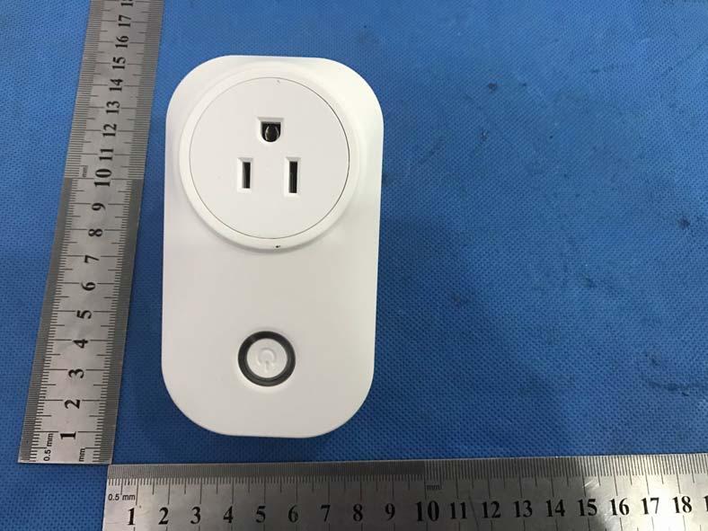
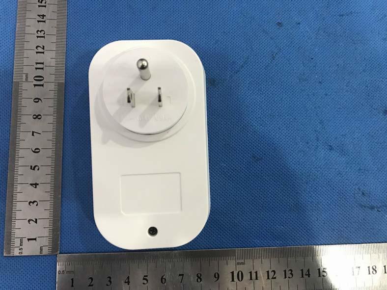
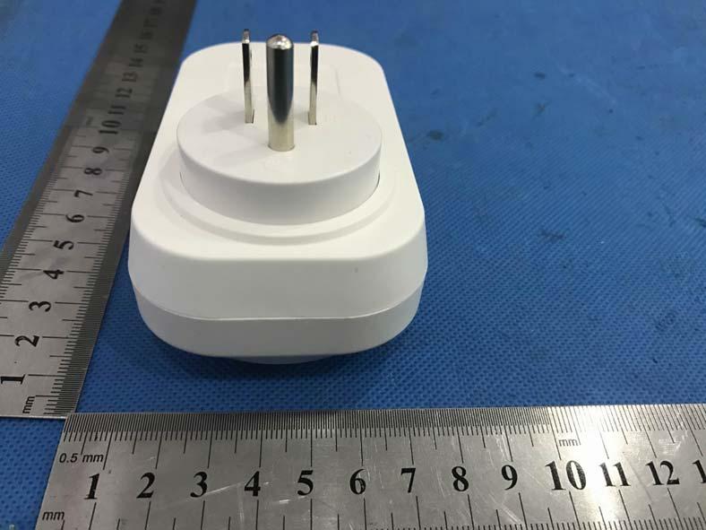
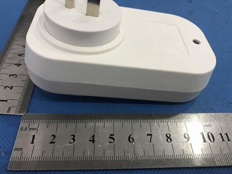
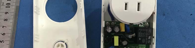
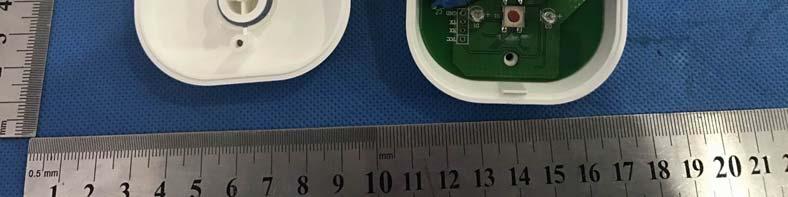
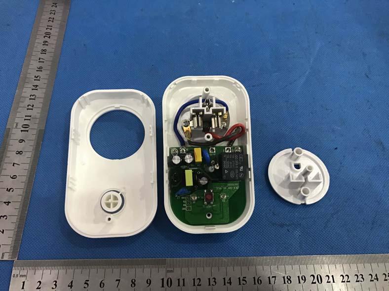
76 Page 76 of 80 7 APPENDIX-Photographs of EUT Constructional Details

77 Page 77 of 80

78 Page 78 of 80

79 Page 79 of 80


80 Page 80 of 80 ANT **End of report**
FCC Test Report. Part 15 subpart C. Prepared By: Shenzhen ECT Testing Technology Co., Ltd.
 Page 1 of 79 Client Information: FCC Test Report Part 15 subpart C Applicant : China Electronics Shenzhen Company Applicant add. : 33/F, BLOCK A, ELECTRONICS SCIENCE & TECHNOLOGY BUILDING, 2070 SHENNAN
Page 1 of 51 Report No.: T TEST REPORT FCC ID: 2AGJ5WAP-30. In Accordance with: FCC PART 15, SUBPART C : 2015 (Section 15.
 Page 1 of 51 Report No.: T1851663 01 TEST REPORT FCC ID: 2AGJ5WAP-30 Applicant Address : Gonsin Conference Equipment Co., Ltd : No.401-406,Block C, Idea Industry Park, No.41 Fengxiang Road, Shunde, Foshan,
TEST REPORT FCC ID: 2ADMF-HC06. : bluetooth module keyes HC-06, keyes hc-05, FUNDUINO HC-06, FUNDUINO hc-05
 Shenzhen Certification Technology Service Co., Ltd. 2F, Building B, East Area of Nanchang Second Industrial Zone, Gushu 2 nd Road, Bao'an District, Shenzhen 518126, P.R. China TEST REPORT FCC ID: 2ADMF-HC06
7. Transmitter Radiated Spurious Emissions and Conducted Spurious Emission
 7. Transmitter Radiated Spurious Emissions and Conducted Spurious Emission 7.1 Test Setup Refer to the APPENDIX I. 7.2 Limit According to 15.247(d), in any 100 khz bandwidth outside the frequency band
Table of Contents 1. GENERAL INFORMATION SYSTEM TEST CONFIGURATION CONDUCTED EMISSIONS TEST RADIATED EMISSION TEST...
 Table of Contents 1. GENERAL INFORMATION... 4 1.1 PRODUCT DESCRIPTION FOR EQUIPMENT UNDER TEST... 4 1.2 RELATED SUBMITTAL(S) / GRANT (S)... 7 1.3 TEST METHODOLOGY... 7 1.4 EQUIPMENT MODIFICATIONS... 7
FCC ID: B4OCC264BPA-S
 FCC TEST REPORT FCC ID: B4OCC264BPA-S Product : Bluetooth LE Module Model Name : CC264BPA-S, CC265BPA-S, CC26xBPA Brand : GT-tronics Report No. : PTC801181160622E-FC01 Prepared for GT-tronics HK Ltd Unit
FCC Test Report. Report No.: PTCDQ FC01
 Page 1 of 63 FCC Test Report Report No.: PTCDQ04170450501-FC01 FCC ID : 2AL2XW801 APPLICATION PURPOSE : Original Equipment PRODUCT DESIGNATION : WIFI DoorBell BRAND NAME : EASTIC MODEL NAME : W801, W802,
ITL Page 2 of 71 Report No.:
 ITL Page 1 of 71 Report No.: 12092752 TEST REPORT Applicant: Address of Applicant: Harman International Industries, Incorporated 8500 Balboa Blvd, Northridge, CA 91329, United States Manufacturer: Address
FCC Part 15C Test Report FCC ID: 2AK8V-WF8300
 FCC Part 15C Test Report FCC ID: 2AK8V-WF8300 Product Name: Trademark: USB type wireless WIFI signal amplifier N/A Model Name : WF8300 Prepared For : Address : Shenzhen Elicks Technology Co., Ltd. No.18
FCC ID: 2ALT5-GW6088
 TEST REPORT FCC ID: 2ALT5-GW6088 For GREAT WORLD LTD Electric Heater Model No. : GW-6078TBT, GW-6088TBT, GW-5088C-AMBT, GW-6088TMBT Trade Name : N/A Prepared for : Address : GREAT WORLD LTD 406 Room 1,
FCC REPORT. Dongguan Hele Electronics Co.,Ltd. * In the configuration tested, the EUT complied with the standards specified above.
 Report No.: GTS201708000040F02 FCC REPORT Applicant: Address of Applicant: Manufacturer: Dongguan Hele Electronics Co.,Ltd. Dalingya Industrial Zone,Daojiao Town,Dongguan City,Guangdong,China Dongguan
FCC CERTIFICATION TEST REPORT
 Report No:DDT-RE120176 Issued Date: 2013/01/05 FCC CERTIFICATION TEST REPORT FOR Applicant : AliMed Inc. Address : 297 High St Dedham Ma 02026 Equipment under Test : Alert transmitter Model No : #712716
For. Unit D16/F. should not use it to claim FCC ID: 2AAIN-MNGLOS
 Page 1 of 49 TESTT REPORT For Applicant : ACOUSTMAX INTERNATIONAL CO.., LTD Unit D16/F Cheuk Nang Plaza 250 Hennessy Road Address : WanchaiHongKong Product Name : Monster GLO Model Name : MNGLO-S, MNGLO-L,MNGLO-M,MNGLO-Mini
FCC REPORT. Dongguan Hele Electronics Co.,Ltd. * In the configuration tested, the EUT complied with the standards specified above.
 + Applicant: Address of Applicant: Manufacturer: FCC REPORT Dongguan Hele Electronics Co.,Ltd. Report No.: GTS201708000040F01 Dalingya Industrial Zone,Daojiao Town,Dongguan City,Guangdong,China Dongguan
FCC TEST REPORT (WIFI) for. TeVii Technology Co., Ltd. wireless HDMI receiver. Model Number: G201RX. Series models:g200rx, VS200VR(RX)
 for. TeVii Technology Co., Ltd. wireless HDMI receiver. Model Number: G201RX. Series models:g200rx, VS200VR(RX)") FCC TEST REPORT (WIFI) for TeVii Technology Co., Ltd. wireless HDMI receiver Model Number: G201RX Series models:g200rx, VS200VR(RX) FCC ID:2ALU5G201RX Prepared for : TeVii Technology Co., Ltd. Address
FCC TEST REPORT (WIFI) for TeVii Technology Co., Ltd. wireless HDMI receiver Model Number: G201RX Series models:g200rx, VS200VR(RX) FCC ID:2ALU5G201RX Prepared for : TeVii Technology Co., Ltd. Address
TABLE OF CONTENTS 1. GENERAL INFORMATION... 4
 TABLE OF CONTENTS 1. GENERAL INFORMATION... 4 1.1. EUT DESCRIPTION... 4 1.2. TEST STANDARDS AND RESULTS... 5 1.3. FACILITIES AND ACCREDITATIONS... 6 1.3.1. FACILITIES... 6 1.3.2. TEST ENVIRONMENT CONDITIONS...
TEST REPORT : 2AIB7MGS. TEST DATE : to
 TEST REPORT APPLICANT : Hohem Technology Co.,Ltd PRODUCT NAME : 3-Axis Stabilizing Gimbal for Smartphone MODEL NAME BRAND NAME FCC ID STANDARD(S) : isteady Mobile : Hohem : 2AIB7MGS : 47 CFR Part 15 Subpart
FCC REPORT. 570 E1 Camino Real #200, Redwood City, CA 94063, United Manufacturer:
 FCC REPORT Applicant: Address of Applicant: Manufacturer: Striiv Inc. 570 E1 Camino Real #200, Redwood City, CA 94063, United States Striiv Inc. Address of 570 E1 Camino Real #200, Redwood City, CA 94063,
TEST REPORT. Issued for: ShenZhen MYGT Co.,LTD D3 Tongfuyu Industrial Area Community of Shajing Town, Baoan, Shenzhen, China.
 TEST REPORT FCC ID: 2AMKEMY-C11 Product: Wireless Gamepad Model No.: MY-C11 Additional Model No.: TKGC01 Trade Mark: N/A Issued Date: Oct. 16, 2017 Issued for: ShenZhen MYGT Co.,LTD D3 Tongfuyu Industrial
FCC PART 15C TEST REPORT FOR CERTIFICATION On Behalf of. Trade Name : Activision. Model Number: / FCC ID: XLU
 FCC PART 15C TEST REPORT FOR CERTIFICATION On Behalf of Activision Publishing, Inc USB Wireless Receiver for Wii & USB Wireless Receiver for PS3 Trade Name : Activision. Model Number: 83973791/84148791
For. Tzone FCC ID: FCC Part Description: Product TZ-BT04. Report to Tested By: Manager STR I
 FCCC Part 15C Measurement and Test For Report Tzone Digitall Technology Co.., LTD 16D, Haiying Building, South of Caitian Road, Futiann District, Shenzhen China FCC ID: 2AKSQTZBT04 FCC Rule(s): Product
RADIO TEST REPORT. For Shenzhen ZD Intelligent Technology Co., Ltd.
 RADIO TEST REPORT For Shenzhen ZD Intelligent Technology Co., Ltd. Product Name: WIFI Camera Model : WXHI130W-V11 WXHI100W-V8 WXHI100W-V9 WXHI100W-V10 ZD-CHI130B-F3 Series Model: ZD-HGM130B-F2 ZD-CHI130B-F4
FCC TEST REPORT. For EASYACC TECHNOLOGY CO., LIMITED Wireless speaker
 FCC ID: 2AJUJ-DP300 Page1 of 46 Report No.: R0217060058W FCC TEST REPORT For EASYACC TECHNOLOGY CO., LIMITED Wireless speaker Model No.: DP300 Prepared For : EASYACC TECHNOLOGY CO., LIMITED Address : UNIT
FCC Part 15C Test Report
 FCC Part 15C Test Report FCC ID: 2AL5W-DFIT Product Name: Trademark: Model Name : Prepared For : Address : Prepared By : smart watch N/A Dfit D8, D8S, D21, DF23, DF30, DB01, DB02, DB03, DB04, DB05, DB06,
FCC Test Report. Report No.: AGC FE08. Attestation of Global Compliance (Shenzhen) Co., Ltd
 Co., Ltd") Page 1 of 27 FCC Test Report Report No.: AGC01039170608FE08 FCC ID : PODTYT-X1U TYPE OF AUTHORIZATION : Certification APPLICATION PURPOSE : Original Equipment PRODUCT DESIGNATION : Analog Transceiver BRAND
Page 1 of 27 FCC Test Report Report No.: AGC01039170608FE08 FCC ID : PODTYT-X1U TYPE OF AUTHORIZATION : Certification APPLICATION PURPOSE : Original Equipment PRODUCT DESIGNATION : Analog Transceiver BRAND
REPORT REVISION HISTORY...
 Reference No.: WTS17S0579239E Page 2 of 39 2 Contents Page 1 COVER PAGE... 1 2 CONTENTS... 2 3 REPORT REVISION HISTORY... 3 4 GENERAL INFORMATION... 4 4.1 GENERAL DESCRIPTION OF E.U.T.... 4 4.2 DETAILS
FCC Part 15C Test Report FCC ID: 2ANYRCBAR-25
 FCC Part 15C Test Report FCC ID: 2ANYRCBAR-25 Product Name: Bluetooth Module Trademark: Model Name : Prepared For : Address : CBAR-25 PT. Eyro Digital Teknologi Jl, Amir Mahmud IX/23 Gunung Anyar, Surabaya
TEST REPORT. Issued for: TICATAG 4 rue Louis de Broglie LANNION FRANCE. Issued By:
 TEST REPORT FCC ID: 2ANX5TIBE Product: Bluetooth Tracker Model No.: Tibe connect Additional Model No.: N/A Trade Mark: N/A Report No.: TCT171018E015 Issued Date: Oct. 27, 2017 Issued for: TICATAG 4 rue
Report No.: BST Y ER 2 RADIO TEST REPORT. For Shenzhen sinocam Technology Co.,LTD.
 RADIO TEST REPORT For Shenzhen sinocam Technology Co.,LTD. Product Name: WIFI IP CAMERA Model : Series Model: FCC ID: SN IPC HW01 SN IPC HW01, SN IPC HW02, SN IPC HW03, SN IPC HW04, SN IPC HW05, SN IPC
SHENZHEN LCS COMPLIANCE TESTING LABORATORY LTD. FCC ID: 2ADPC-G6 Report No.: LCS E
 2) Sequence of testing 30 to 1 GHz Setup: --- The equipment was set up to simulate a typical usage like described in the user manual or described by manufacturer. --- If the EUT is a tabletop system, a
FCC Test Report. Report No.: AGC FE03. MODEL NAME : Ci3, Ti3, CB3, AO, UI, Vinyl I, Vinyl B, M2
 Page 1 of 51 FCC Test Report FCC ID : VO8CI3 APPLICATION PURPOSE : Original Equipment PRODUCT DESIGNATION : Bluetooth headset BRAND NAME : Bluedio MODEL NAME : Ci3, Ti3, CB3, AO, UI, Vinyl I, Vinyl B,
TEST REPORT. Reference No... : WTS16S E FCC ID... : SJ8-UDR777HD. Applicant... : RDI Technology Shenzhen Co., Ltd.
 TEST REPORT Reference No.... : WTS16S0449305E FCC ID... : SJ8-UDR777HD Applicant... : RDI Technology Shenzhen Co., Ltd. Address... : Building C1, Xintang Industrial Park East Baishixia, Fuyong, Baoan,
FCC Test Report. Report No.: AGC FE03. : Shenzhen Liangzi Zhineng Technology Co., Ltd. Attestation of Global Compliance (Shenzhen) Co.
 Co.") Page 1 of 70 FCC Test Report Report No.: AGC06913160501FE03 FCC ID APPLICATION PURPOSE PRODUCT DESIGNATION BRAND NAME : 2AIM7JAZZ6 : Original Equipment : Bluetooth Headset : BlueFit, Kavoxii MODEL NAME
Page 1 of 70 FCC Test Report Report No.: AGC06913160501FE03 FCC ID APPLICATION PURPOSE PRODUCT DESIGNATION BRAND NAME : 2AIM7JAZZ6 : Original Equipment : Bluetooth Headset : BlueFit, Kavoxii MODEL NAME
FCC REPORT. Dongguan Hele Electronics Co., Ltd. J11, J12, J13, Q7, Q28, Q26, Q29
 FCC REPORT Applicant: Dongguan Hele Electronics Co., Ltd. Address of Applicant: Dalingya Industrial Zone, Daojiao Town, Dongguan City, Guangdong China Equipment Under Test (EUT) Product Name: Model No.:
FCC PART 15C TEST REPORT FOR CERTIFICATION On Behalf of. Sony Corporation. Wireless Speaker SRS-XB10 FCC ID: AK8SRSXB10
 FCC ID: AK8SRSXB10 FCC PART 15C TEST REPORT FOR CERTIFICATION On Behalf of Sony Corporation Wireless Speaker SRS-XB10 FCC ID: AK8SRSXB10 Prepared for : Sony Corporation 1-7-1 Konan Minato-ku Tokyo, 108-0075
FCC PART 15C TEST REPORT FOR CERTIFICATION On Behalf of. Sony Corporation. Home Audio System GTK-XB90 FCC ID: AK8GTKXB90
 FCC ID:AK8GTKXB90 FCC PART 15C TEST REPORT FOR CERTIFICATION On Behalf of Sony Corporation Home Audio System GTK-XB90 FCC ID: AK8GTKXB90 Prepared for : Sony Corporation 1-7-1 Konan Minato-ku Tokyo, 108-0075
FCC & RSS-216 (Class II Permissive Change) Wireless Power Transfer Report. for A Acer Incorporated
 Wireless Power Transfer Report. for A Acer Incorporated") Page 1 of 17 FCC 15.209 & RSS-216 (Class II Permissive Change) Wireless Power Transfer Report for A Acer Incorporated 8F., No.88, Sec. 1, Xintai 5th Rd., Xizhi, New Taipei City 22181, Taiwan (R.O.C) Product
Page 1 of 17 FCC 15.209 & RSS-216 (Class II Permissive Change) Wireless Power Transfer Report for A Acer Incorporated 8F., No.88, Sec. 1, Xintai 5th Rd., Xizhi, New Taipei City 22181, Taiwan (R.O.C) Product
Test Report Version. Test Report No. Date Description. DRTFCC Sep. 12, 2014 Initial issue
 DEMC1407-02828 FCC ID: 2AAAQH660W Test Report Version Test Report No. Date Description DRTFCC1409-1165 Sep. 12, 2014 Initial issue Page 2 DEMC1407-02828 FCC ID: 2AAAQH660W Table of Contents 1. EUT DESCRIPTION...
FCC PART 15C TEST REPORT FOR CERTIFICATION On Behalf of. Proware Technologies Co., Ltd. Wireless High Gain USB Adapter. Model No.
 FCC PART 15C TEST REPORT FOR CERTIFICATION On Behalf of Proware Technologies Co., Ltd. Wireless High Gain USB Adapter Model No.: PW-DN4210D FCC ID: WWMDN4210DV1 Prepared for : Proware Technologies Co.,
FCC REPORT. 2AKQO-Q740 FCC CFR Title 47 Part 15 Subpart C. * In the configuration tested, the EUT complied with the standards specified above.
 FCC REPORT Applicant: Address of Applicant: Manufacturer/Factory: Address of Manufacturer/Factory: Guangzhou Smamao Electronic Technology Co.,Ltd Room 811, Building 8, No.315, Central City, Middle Road,
FCC Test Report. Report No.: AGC FE04. Attestation of Global Compliance (Shenzhen) Co., Ltd
 Co., Ltd") Page 1 of 74 FCC Test Report Report No.: AGC07248170302FE04 FCC ID : TV7WBM APPLICATION PURPOSE : Original Equipment PRODUCT DESIGNATION : Woobm-USB BRAND NAME : N/A MODEL NAME : Woobm-USB CLIENT : Mikrotikls
Page 1 of 74 FCC Test Report Report No.: AGC07248170302FE04 FCC ID : TV7WBM APPLICATION PURPOSE : Original Equipment PRODUCT DESIGNATION : Woobm-USB BRAND NAME : N/A MODEL NAME : Woobm-USB CLIENT : Mikrotikls
FCC RF TEST REPORT No SHA-001
 Page 1 of 41 FCC RF TEST REPORT No. 180300344SHA-001 Applicant : Stanley Black & Decker, Inc. 400 Executive Blvd S, Southington, CT 06489 USA Manufacturer : Northwest Instrument Inc. 330 Waterloo Valley
FCC Part 15C Test Report FCC ID: 2ALQA-LIVE
 FCC Part 15C Test Report FCC ID: 2ALQA-LIVE Product Name: Wifi video doorbell Trademark: Model Name : Prepared For : DB-HD-LIVE DB-HD-PRO, DB-HDL, DB-HDX2, DB-HDX3, DB-HDX4, DB-HDX5, DB-CAM-L, DB-CAM-X2,
APPLICATION FOR CERTIFICATION On Behalf of Futaba Corporation Radio Control Model No.:T10CG-2.4G FCC ID:AZPT10CG-24G Brand : Futaba
 FCC ID. AZPT10CG-24G Page 1 of 56 APPLICATION FOR CERTIFICATION On Behalf of Futaba Corporation Radio Control Model No.:T10CG-2.4G FCC ID:AZPT10CG-24G Brand : Futaba Prepared for : Futaba Corporation 1080
RSS-247 TEST REPORT FOR CERTIFICATION On Behalf of. Sony Corporation. Home Audio System. Model No.: GTK-XB7 IC: 409B-GTKXB7
 IC:409B-GTKXB7 RSS-247 TEST REPORT FOR CERTIFICATION On Behalf of Sony Corporation Home Audio System Model No.: GTK-XB7 IC: 409B-GTKXB7 Prepared for : Sony Corporation 1-7-1 Konan, Minato-ku, Tokyo 108-0075
FCC 47 CFR PART 15 SUBPART C INDUSTRY CANADA RSS-210 ISSUE 8 BLUETOOTH LOW ENERGY CERTIFICATION TEST REPORT FOR. 2.4GHz LE MODULE MODEL NUMBER: RN4020
 FCC 47 CFR PART 15 SUBPART C INDUSTRY CANADA RSS-210 ISSUE 8 BLUETOOTH LOW ENERGY CERTIFICATION TEST REPORT FOR 2.4GHz LE MODULE MODEL NUMBER: RN4020 REPORT NUMBER: 14U17191-1 ISSUE DATE: MARCH 21, 2014
TEST REPORT. Shenzhen, PRC.
 TEST REPORT Reference No.... : WTS16S0449309E FCC ID... : SJ8-UDRC57 Applicant... : RDI Technology Shenzhen Co., Ltd. Address... : Building C1, Xintang Industrial Park East Baishixia, Fuyong, Baoan, Shenzhen,
RADIO TEST REPORT. Report No: STS F01. Issued for KINGFISH ELECTRONICS CO., LIMITED. Bluetooth headset
 S T S RADIO TEST REPORT Report No: STS1701097F01 Issued for KINGFISH ELECTRONICS CO., LIMITED 207-216 rooms, Huachuangda commercial building, Cuizu Rd, 46 area bao'an, shenzhen, China L Product Name: Bluetooth
FCC REPORT. Lightcomm Technology Co., Ltd.
 FCC REPORT Report No.: GTS201608000267E01 Applicant: Lightcomm Technology Co., Ltd. Address of Applicant: RM 1808 18/F FO TAN INDUSTRIAL CENTRE NOS. 26-28 AU PUI WAN STREET FO TAN SHATIN NEW TERRITORIES
9. MAXIMUM CONDUCTED OUTPUT POWER SPECTRAL DENSITY
 9. MAXIMUM CONDUCTED OUTPUT POWER SPECTRAL DENSITY 9.1. MEASUREMENT PROCEDURE (1). Connect EUT RF output port to the Spectrum Analyzer through an RF attenuator (2). Set the EUT Work on the top, the middle
FCC PART 15C TEST REPORT FOR CERTIFICATION On Behalf of. ION Audio, LLC. Portable Karaoke PA speaker with vocal effects
 FCC PART 15C TEST REPORT FOR CERTIFICATION Behalf of ION Audio, LLC Portable Karaoke PA speaker with vocal effects Model Number: ipk3 KARAOKE STAR PLUS FCC ID: 2AB3E-IPK3 Prepared for: Prepared By: ION
Description of Test Facility
 Description of Test Facility Name: Address: Intertek Testing Services Limited Shanghai Building No.86, 1198 Qinzhou Road(North), Shanghai 200233, P.R. China FCC Registration Number: 236597 IC Assigned
RF TEST REPORT for Intentional Radiator No SHA-001
 RF TEST REPORT for Intentional Radiator No. 160600514SHA-001 Applicant : Shanghai Ruipai Intelligent Technology Co.,Ltd. B105, Building 9, Wusong Science Park, No.69 Tieshan Rd., Baoshan District, Shanghai,
Table of Contents 1. GENERAL INFORMATION SYSTEM TEST CONFIGURATION CONDUCTED EMISSIONS TEST... 12
 Table of Contents 1. GENERAL INFORMATION... 5 1.1 PRODUCT DESCRIPTION FOR EQUIPMENT UNDER TEST... 5 1.2 RELATED SUBMITTAL(S) / GRANT (S)... 8 1.3 TEST METHODOLOGY... 8 1.4 EQUIPMENT MODIFICATIONS... 8
TEST REPORT. Issued for: RUIMA INTERNATIONAL(HK)INDUSTRIAL CO.,LIMITED NO.19 Ruixiang Road, Xinhua Industrial Zone, Huadu District, Guangzhou China
INDUSTRIAL CO.,LIMITED NO.19 Ruixiang Road, Xinhua Industrial Zone, Huadu District, Guangzhou China") TEST REPORT FCC ID: 2AHSJRM-626B Product: Boombox Speaker Model No.: RM-626 Additional Model: STREET HOPPER 6, CANNON 6 Trade Mark: RUIMA Issued Date: Aug. 04, 2016 Issued for: RUIMA INTERNATIONAL(HK)INDUSTRIAL
TEST REPORT FCC ID: 2AHSJRM-626B Product: Boombox Speaker Model No.: RM-626 Additional Model: STREET HOPPER 6, CANNON 6 Trade Mark: RUIMA Issued Date: Aug. 04, 2016 Issued for: RUIMA INTERNATIONAL(HK)INDUSTRIAL
FCC PART 15C TEST REPORT FOR CERTIFICATION On Behalf of. DEI Sales Inc. dba Definitive Technology. Model Number: STUDIO SLIM SUBWOOFER
 FCC PART 15C TEST REPORT FOR CERTIFICATION On Behalf of DEI Sales Inc. dba Definitive Technology 3.1 Home Theater Sound Bar and Wireless Subwoofer System Model Number: STUDIO SLIM SUBWOOFER FCC ID: IPUSTUSLIMSUB
Revision history. Revision Date of issue Test report No. Description KES-RF-14T0042 Initial
 Page (2 ) of (34) Revision history Revision Date of issue Test report No. Description - 2014.08.25 Initial Page (3 ) of (34) TABLE OF CONTENTS 1. General information... 4 1.1. EUT description... 4 1.2.
TEST REPORT. For. Model Name : Maestro T4HU1608, Maestro T4HUXXXX (X is 0 to 9) Issued by : Most Technology Service Co., Limited.
 Issued by : Most Technology Service Co., Limited.") TEST REPORT For Applicant : Address : Product Name : Tech4home, Lda Rua de Fundoes, No.151, 3700-121 Sao Joao da Madeira, Portugal Remote Control Unit Model Name : Maestro T4HU1608, Maestro T4HUXXXX (X
TEST REPORT For Applicant : Address : Product Name : Tech4home, Lda Rua de Fundoes, No.151, 3700-121 Sao Joao da Madeira, Portugal Remote Control Unit Model Name : Maestro T4HU1608, Maestro T4HUXXXX (X
FCC Test Report. Report No.: AGC FE03. Attestation of Global Compliance (Shenzhen) Co., Ltd
 Co., Ltd") Page 1 of 55 FCC Test Report FCC ID : XELA01 APPLICATION PURPOSE : Original Equipment PRODUCT DESIGNATION : Bluetooth Headset BRAND NAME : ORiCORE MODEL NAME : A01 CLIENT : DATE OF ISSUE : Nov.30, 2016
Page 1 of 55 FCC Test Report FCC ID : XELA01 APPLICATION PURPOSE : Original Equipment PRODUCT DESIGNATION : Bluetooth Headset BRAND NAME : ORiCORE MODEL NAME : A01 CLIENT : DATE OF ISSUE : Nov.30, 2016
ELECTROMAGNETIC EMISSIONS COMPLIANCE REPORT
 Page: 1 of 57 ELECTROMAGNETIC EMISSIONS COMPLIANCE REPORT INTENTIONAL RADIATOR CERTIFICATION TO FCC PART 15 SUBPART C REQUIREMENT OF Product name: Brand Name: Model Name: FCC ID: REPORT NO: Bluetooth Headset
FCC TEST REPORT. SHENZHEN MORLAB COMMUNICATIONS TECHNOLOGY Co., Ltd.
 FCC TEST REPORT APPLICANT : GN Netcom Inc PRODUCT NAME : Bluetooth Headsets MODEL NAME : HSC040W TRADE NAME : N/A BRAND NAME : Jabra FCC ID : BCE-HSC040W STANDARD(S) : 47 CFR Part 15 Subpart B TEST DATE
Ave output power ANT 1(dBm) Ave output power ANT 2 (dbm)
 Ave output power ANT 2 (dbm)") Page 41 of 103 9.6. Test Result The test was performed with 802.11b Channel Frequency (MHz) power ANT 1(dBm) power ANT 2 (dbm) power ANT 1(mW) power ANT 2 (mw) Limits dbm / W Low 2412 7.20 7.37 5.248 5.458
Page 41 of 103 9.6. Test Result The test was performed with 802.11b Channel Frequency (MHz) power ANT 1(dBm) power ANT 2 (dbm) power ANT 1(mW) power ANT 2 (mw) Limits dbm / W Low 2412 7.20 7.37 5.248 5.458
ELECTROMAGNETIC EMISSIONS COMPLIANCE REPORT
 Page: 1 of 54 ELECTROMAGNETIC EMISSIONS COMPLIANCE REPORT INTENTIONAL RADIATOR CERTIFICATION TO FCC PART 15 SUBPART C REQUIREMENT FULL MODULE APPROVE OF Product Name: Brand Name: Model Name: Model Differences:
Test Report FCC ID: 2APBP-CS10. Date of issue: Apr. 10, 2018 CS10, CS10A, CS10B, CS10C, CS10D, CS10E, CS10F, CS11, CS12, CS13
 Test Report FCC ID: 2APBP-CS10 Date of issue: Apr. 10, 2018 Report Number: MTi180416E035 Sample Description: Smart POS Payment Terminal Model(s): CS10, CS10A, CS10B, CS10C, CS10D, CS10E, CS10F, CS11, CS12,
INDEX. Table of contents. 1. General information
 Report Number: F690501/RF-RTL009892-1 Page: 2 of 72 INDEX Table of contents 1. General information -------------------------------------------------------------------------------------- 3 2. Transmitter
FCC Part 15C Test Report FCC ID: 2AFKNE100W
 FCC Part 15C Test Report FCC ID: 2AFKNE100W Product Name: Trademark: Wireless DoorBell Spigen Model Name : E100W Prepared For : Address : Prepared By : Spigen Korea Co., Ltd. N0. 1709 STX-V Tower, 371-37,
Version TEST REPORT NO. DATE DESCRIPTION
 Version NO. DATE DESCRIPTION HCTR1302FR13 February 14, 2013 - First Approval Report - Additional Model Name Page 2 of 25 Table of Contents 1. GENERAL INFORMATION... 4 2. EUT DESCRIPTION... 4 3. TEST METHODOLOGY...
TEST REPORT WTN16S E 2AFOYL654UCNN
 TEST REPORT Reference No.... : FCC ID... : Applicant... : Address... : Manufacturer... : Address... : Product Name... : Model No..... : Brand.... WTN16S0754892-1E 2AFOYL654UCNN Le Shi Zhi Xin Electronic
TEST REPORT. Issued for:
 TEST REPORT FCC ID: 2ALPZ- AA00277W Product: Handsfree car kit with FM Transmitter Model No.: AA00277W Additional Model: AA00277G Trade Mark: N/A Report No.: TCT170331E007 Issued Date: Apr. 14, 2017 Issued
Title: Test on 5.8 GHz Band Outdoor WiFi (802.11b/g) Wireless Base Station
 Wireless Base Station") Page 20 of 51 Pages 7.5. Conducted spurious emission 7.5.1. Requirements: Clause 15.247(d). In any 100 khz bandwidth outside the frequency band in which the spread spectrum or digitally modulated intentional
Page 20 of 51 Pages 7.5. Conducted spurious emission 7.5.1. Requirements: Clause 15.247(d). In any 100 khz bandwidth outside the frequency band in which the spread spectrum or digitally modulated intentional
FCC AND IC CERTIFICATION TEST REPORT
 Issued Date: Mar. 8, 205 FCC AND IC CERTIFICATION TEST REPORT FOR Applicant : Harman International Industries, Incorporated Address : 8500 Balboa Blvd, Northridge, CA 9329, UNITED STATES Equipment under
FCC TEST REPORT. According to. FCC Rules and Regulations Part 15 Subpart C
 FCC TEST REPORT According to FCC Rules and Regulations Part 15 Subpart C Applicant : Billion Electric Co., Ltd. Address : 8F., No. 192, Sec. 2, Zhongxing Road, Xindian Dist., New Taipei City, Taiwan Equipment
ELECTROMAGNETIC EMISSIONS COMPLIANCE REPORT INTENTIONAL RADIATOR CERTIFICATION TO FCC PART 15 SUBPART C REQUIREMENTS. LIFX GU10 Wi-Fi Downlight
 ELECTROMAGNETIC EMISSIONS COMPLIANCE REPORT INTENTIONAL RADIATOR CERTIFICATION TO FCC PART 15 SUBPART C REQUIREMENTS OF LIFX GU10 Wi-Fi Downlight MODEL No.: BUL-11-GU10-G FCC ID: 2AA53-LIFX02 Trade Mark:
RADIO TEST REPORT. Report No: STS W02. Issued for. OBDSTAR Technology Co., Ltd. Key Master DP PLUS N/A DP80 2AJ2DDP80
 S T S RADIO TEST REPORT Report No: STS1708081W02 Issued for OBDSTAR Technology Co., Ltd West Block 4 floor,no. 8 building of Xinwu industrial areas, Taoyuan street, Nanshan District, Shenzhen, China L
TEST REPORT. For RFID READER/WRITER. In conformity with. FCC CFR 47 Part15 Subpart C
 TEST REPORT For RFID READER/WRITER In conformity with FCC CFR 47 Part15 Subpart C Model: TR3XM-SD01 / TR3XM-SU01 / TR3XM-SN01 FCC ID: MK4TR3XM-SX01 Test Item: RFID READER/WRITER Report No: RY1203Z12R1
FCC RADIO TEST REPORT FCC ID: 2AML6BB898
 1 of 41 - FCC RADIO TEST REPORT FCC ID: 2AML6BB898 Product: Bluetooth earphone Trade Name: KINGRAY Model Name: BB898 Addition Model: MG0478,BB897,BB890,BB491,BB497,BB498, KR166,KR600,KR658,KR385,KR875,BB959,
IC Test Report. : 3147A-BT900US : Intelligent BT4.0 Dual Mode USB Dongle
 IC Test Report IC Equipment Model No. Brand Name Applicant : 3147A-BT900US : Intelligent BT4.0 Dual Mode USB Dongle : BT900-US : Laird Technologies : Laird Technologies Address : 11160 Thompson Ave., Lenexa,
FCC Test Report. Wayne Hsu / Assistant Manager
 FCC Test Report Equipment : Wireless Pedometer/Tracker Brand Name : ASE Group Model No. : M903 Standard : 47 CFR FCC Part 15.247 Operating Band : 2400 MHz 2483.5 MHz FCC Classification : DTS Applicant
FCC 47 CFR PART 15 SUBPART C
 FCC 47 CFR PART 15 SUBPART C Product Type Applicant Address Trade Name Model Number : Wink Relay : Quirky, Inc. : 606 W 28th St, Floor 7 New York NY 10001 United States : Wink : PRLAY-WH01 Test Specification
No. 620 HuaYuan Commercial Center, No. 347 XiXiang Road,XiXiang Town, Bao An District, ShenZhen City Tel : Fax:
 No. 620 HuaYuan Commercial Center, No. 347 XiXiang Road,XiXiang Town, Bao An District, ShenZhen City Tel : +86-755-27912080 Fax: +86-755-27916936 FCC TEST REPORT Product name : 7PORT DUAL SUPPLY POE SWITCH
FCC TEST REPORT. According to CFR
 FCC TEST REPORT According to CFR47 15.247 Applicant : IFLYTEK CO.,LTD Address : West Wangjiang Rd.666,Hefei,Anhui, China Manufacturer : IFLYTEK CO.,LTD Address : West Wangjiang Rd.666,Hefei,Anhui, China
FCC PART MEASUREMENT AND TEST REPORT FOR. Guangzhou Walkera Technology CO., LTD
 FCC PART 15.249 MEASUREMENT AND TEST REPORT FOR Guangzhou Walkera Technology CO., LTD Taishi Industrial Park, Yuwoto Town, Panyu District, 511475 Guangzhou, China. FCC ID: S29WK-2801PRO Report Concerns:
FCC TEST REPORT. For Fusion Sport Proprietary Limited Smartspeed PT Model No.: Smartspeed PT 1.00
 FCC ID: 2AQJC-PT100 Page 1 of 64 Report No.: SZAWW180703002-01 FCC TEST REPORT For Fusion Sport Proprietary Limited Smartspeed PT Model No.: Smartspeed PT 1.00 Prepared For : Fusion Sport Proprietary Limited
FCC CFR47 PART 15 SUBPART C INDUSTRY CANADA RSS-GEN AND RSS-210 CERTIFICATION TEST REPORT FOR BROADCOM BLUETOOTH MODULE MODEL NUMBER: BCM92046MD
 FCC CFR47 PART 15 SUBPART C INDUSTRY CANADA RSS-GEN AND RSS-210 CERTIFICATION TEST REPORT FOR BROADCOM BLUETOOTH MODULE MODEL NUMBER: BCM92046MD IC #: 4324A-BRCM1029 REPORT NUMBER: 07U11199-1C ISSUE DATE:
FCC TEST REPORT. For Shenzhen Qinps Technology Co., Ltd Soundcircularbluetooth speaker
 FCC ID: 2ANLQ-BTSC001 Page 1 of 61 Report No.: R0217080079W1 FCC TEST REPORT For Shenzhen Qinps Technology Co., Ltd Soundcircularbluetooth speaker Model No.: BTSC001, BTSC Prepared For : Shenzhen Qinps
IC Test Report. : 3147A-BT800 : BTv4.0 Dual Mode USB HCI Module : BT800 refer to item for more details
 IC Test Report IC Equipment Model No. Brand Name Applicant : 3147A-BT800 : BTv4.0 Dual Mode USB HCI Module refer to item 1.1.1 for more details : BT800 refer to item 1.1.1 for more details : Laird Technologies
MEASUREMENT REPORT FCC PART & IC RSS-247 Bluetooth v4.1
 MRT Technology (Suzhou) Co., Ltd Report No.: 1512RSU00101 Phone: +86-512-66308358 Report Version: V03 Fax: +86-512-66308368 Issue Date: 04-21-2016 Web: www.mrt-cert.com MEASUREMENT REPORT FCC PART 15.247
FCC RADIO TEST REPORT FCC ID: 2ACNAKBT10
 FCC RADIO TEST REPORT FCC ID: 2ACNAKBT10 Product: BLUE TOOTH KEYBOARD AND BAG Trade Name: / Model Name: KBT10 Serial Model: KBT8 Prepared for AHCOF INTERNATIONAL DEVELOPMENT CO.LTD 11-14FL SUNON PLAZA
FCC Test Report. : 2ACKD-WIM : Wireless access point module
 FCC Test Report FCC ID Equipment Model No. Brand Name Applicant Address : 2ACKD-WIM1200-20 : Wireless access point module : WIM1200-20 : SKSPRUCE : SKSpruce Technologies Inc. : 1885 Lundy Ave. Suite 270,
FCC 47 CFR PART 15 SUBPART C AND ANSI C63.10:2013 TEST REPORT
 FCC 47 CFR PART 15 SUBPART C AND ANSI C63.10:2013 TEST REPORT For ZigBee Module Model: MD1000 Trade Name: Billion Issued for Billion Electric Co., Ltd. 8F., No.192, Sec. 2, Zhongxing Rd., Xindian Dist.,
FCC PART 15C TEST REPORT FOR CERTIFICATION On Behalf of. Bang & Olufsen a/s. Bluetooth Speaker. Model Number: Beolit 17 FCC ID: TTUBEOLIT17
 FCC PART 15C TEST REPORT FOR CERTIFICATION On Behalf of Bang & Olufsen a/s Bluetooth Speaker Model Number: Beolit 17 FCC ID: TTUBEOLIT17 Prepared for : Bang & Olufsen a/s Peter Bangs Vej 15, 7600 Struer,
IC Test Report. : 3147A-BT850 : Bluetooth 4.2 Dual Mode USB HCI Module (Refer to item for more details) (Refer to item for more details)
 (Refer to item for more details)") IC Test Report IC Equipment Model No. Brand Name Applicant Address : 3147A-BT850 : Bluetooth 4.2 Dual Mode USB HCI Module (Refer to item 1.1.1 for more details) : BT850-SA (Refer to item 1.1.1 for more
IC Test Report IC Equipment Model No. Brand Name Applicant Address : 3147A-BT850 : Bluetooth 4.2 Dual Mode USB HCI Module (Refer to item 1.1.1 for more details) : BT850-SA (Refer to item 1.1.1 for more
Test Report. Applicant ASUSTeK COMPUTER INC. 4F, No. 150, Li-Te Rd., Peitou, Taipei, Taiwan. Date of Receipt Jan. 28, Issued Date Mar.
 Test Report Product Name Model No. FCC ID. IC ID. WPC Qi 1.1/1.0 compliance wireless charging micro-usb box Wireless Charger MSQ-ASUSWLCHARGER 3568A-ASWLCHARGER Applicant ASUSTeK COMPUTER INC. Address
FCC TEST REPORT FCC ID: 2ALCFXO-9319
 Product : Bluetooth Speaker FCC TEST REPORT FCC ID: 2ALCFXO-9319 Model Name : XO-9319 Brand : N/A Report No. : PTCDQ01170710302-FC01 Prepared for Dongguan Xing Yue Electronic co., Ltd #98 LiWu Swan Industrial
ELECTROMAGNETIC EMISSIONS COMPLIANCE REPORT
 Page: 1 of 53 ELECTROMAGNETIC EMISSIONS COMPLIANCE REPORT INTENTIONAL RADIATOR CERTIFICATION TO FCC PART 15 SUBPART C REQUIREMENT FULL MODULAR APPROVAL OF Product Name: Brand Name: Model Name: Model Difference:
Jul. 16, Jun. 04, Shenzhen. Tel:(86-755)
") Test Report FCC ID.: MTi160413E004 Date of issue: Jul. 16, 2016 Sample Description: Wireless POS Terminal Model(s): G3 Applicant: Shenzhen Xinguodu Technology Co., Ltd. Address: 17/A, Jinsong Building
Test Report FCC ID.: MTi160413E004 Date of issue: Jul. 16, 2016 Sample Description: Wireless POS Terminal Model(s): G3 Applicant: Shenzhen Xinguodu Technology Co., Ltd. Address: 17/A, Jinsong Building
FCC Test Report. : abgn M.2 module w/usb interface
 FCC Test Report FCC ID Equipment Model No. Brand Name Applicant : SQG-M2US50NBT : 802.11abgn M.2 module w/usb interface : M2US50NBT : Laird Technologies : Laird Technologies Address : 11160 Thompson Ave.,
ACCORDING TO: FCC part 15 subpart C, and subpart B FOR:
 Electrical Hermon Laboratories Ltd. P.O.Box 23, Binyamina 30500, Israel Tel. +972 4628 8001 Fax. +972 4628 8277 E-mail: mail@hermonlabs.com TEST REPORT ACCORDING TO: FCC part 15 subpart C, 15.247 and subpart
TEST REPORT. Issued for: Marvelmind Robotics Lugovaya str., 4 bld 5 room 17, Skolkovo Innovation Center, Moscow, , Russian Federation
 TEST REPORT FCC ID: 2AL2L915MHZM Product: Modem 915MHz v4.95 Model No.: 915MHz Additional Model No.: N/A Trade Mark: N/A Report No.: TCT170720E008 Issued Date: Aug. 31, 2017 Issued for: Marvelmind Robotics
King Pigeon Communication Co., Limited
 APPLICATION FOR ELECTROMAGNETIC COMPATIBILITY DIRECTIVE On Behalf of King Pigeon Communication Co., Limited Remote Controller RTU Model No.: S130, S140, S150, S180, S25x, S26x, S27x, RTU501x, RTU502x,