TEST REPORT. Issued for: Marvelmind Robotics Lugovaya str., 4 bld 5 room 17, Skolkovo Innovation Center, Moscow, , Russian Federation
|
|
|
- Alfred Alexander
- 5 years ago
- Views:
Transcription
1 TEST REPORT FCC ID: 2AL2L915MHZM Product: Modem 915MHz v4.95 Model No.: 915MHz Additional Model No.: N/A Trade Mark: N/A Report No.: TCT170720E008 Issued Date: Aug. 31, 2017 Issued for: Marvelmind Robotics Lugovaya str., 4 bld 5 room 17, Skolkovo Innovation Center, Moscow, , Russian Federation Issued By: Shenzhen Tongce Testing Lab. 1B/F., Building 1, Yibaolai Industrial Park, Qiaotou, Fuyong, Baoan District, Shenzhen, Guangdong, China TEL: FAX: Note: This report shall not be reproduced except in full, without the written approval of Shenzhen Tongce Testing Lab. This document may be altered or revised by Shenzhen Tongce Testing Lab. personnel only, and shall be noted in the revision section of the document. The test results in the report only apply to the tested sample.
2 TABLE OF CONTENTS Report No.: TCT170720E Test Certification Test Result Summary EUT Description Genera Information Test environment and mode Description of Support Units Facilities and Accreditations Facilities Location Measurement Uncertainty Test Results and Measurement Data Antenna requirement Conducted Emission Conducted Output Power dB Occupy Bandwidth Carrier Frequencies Separation Hopping Channel Number Dwell Time Pseudorandom Frequency Hopping Sequence Conducted Band Edge Measurement Conducted Spurious Emission Measurement Radiated Spurious Emission Measurement Appendix A: Photographs of Test Setup Appendix B: Photographs of EUT Page 2 of 45
3 1. Test Certification Report No.: TCT170720E008 Product: Modem 915MHz v4.95 Model No.: Additional Model: Trade Mark: Applicant: Address: 915MHz N/A N/A Marvelmind Robotics Lugovaya str., 4 bld 5 room 17, Skolkovo Innovation Center, Moscow, , Russian Federation Manufacturer: Marvelmind Robotics Address: Lugovaya str., 4 bld 5 room 17, Skolkovo Innovation Center, Moscow, , Russian Federation Date of Test: Jul. 20 Aug. 30, 2017 Applicable Standards: FCC CFR Title 47 Part 15 Subpart C Section The above equipment has been tested by Shenzhen Tongce Testing Lab. and found compliance with the requirements set forth in the technical standards mentioned above. The results of testing in this report apply only to the product/system, which was tested. Other similar equipment will not necessarily produce the same results due to production tolerance and measurement uncertainties. Tested By: Date: Aug. 30, 2017 Jin Wang Reviewed By: Date: Aug. 31, 2017 Joe Zhou Approved By: Date: Aug. 31, 2017 Tomsin Page 3 of 45
4 2. Test Result Summary Report No.: TCT170720E008 Requirement CFR 47 Section Result Antenna Requirement / (c) PASS AC Power Line Conducted Emission PASS Conducted Peak Output Power 20dB Occupied Bandwidth (b)(2) (a)(1) PASS PASS Carrier Frequencies Separation (a)(1) PASS Hopping Channel Number (a)(1) PASS Dwell Time (a)(1) PASS Radiated Emission Band Edge / , (d) , PASS PASS Note: 1. PASS: Test item meets the requirement. 2. Fail: Test item does not meet the requirement. 3. N/A: Test case does not apply to the test object. 4. The test result judgment is decided by the limit of test standard. Page 4 of 45
5 3. EUT Description Report No.: TCT170720E008 Product Name: Modem 915MHz v4.95 Model : Additional Model: Trade Mark: Operation Frequency: 915MHz N/A N/A 903MHz~927MHz Number of Channel: 25 Modulation Type: Antenna Type: Antenna Gain: Power Supply: GFSK External Antenna 2.0dBi DC5.0V from USB Port of Notebook Operation Frequency each of channel for GFSK Channel Frequency Channel Frequency Channel Frequency Channel Frequency 1 903MHz 8 910MHz MHz MHz 2 904MHz 9 911MHz MHz MHz 3 905MHz MHz MHz MHz 4 906MHz MHz MHz MHz 5 907MHz MHz MHz 6 908MHz MHz MHz 7 909MHz MHz MHz Remark: Channel 0, 13 &25 have been tested for GFSK modulation mode. Page 5 of 45
6 4. Genera Information 4.1. Test environment and mode Report No.: TCT170720E008 Operating Environment: Temperature: 25.0 C Humidity: Atmospheric Pressure: 56 % RH 1010 mbar Test Mode: Engineering mode: Keep the EUT in continuous transmitting by select channel and modulations with Fully-charged battery The sample was placed 0.8m & 1.5m for the measurement below & above 1GHz above the ground plane of 3m chamber. Measurements in both horizontal and vertical polarities were performed. During the test, each emission was maximized by: having the EUT continuously working, investigated all operating modes, rotated about all 3 axis (X, Y & Z) and considered typical configuration to obtain worst position, manipulating interconnecting cables, rotating the turntable, varying antenna height from 1m to 4m in both horizontal and vertical polarizations. The emissions worst-case are shown in Test Results of the following pages Description of Support Units The EUT has been tested as an independent unit together with other necessary accessories or support units. The following support units or accessories were used to form a representative test configuration during the tests. Equipment Model No. Serial No. FCC ID Trade Name Notebook G485 / / Lenove Note: 1. All the equipment/cables were placed in the worst-case configuration to maximize the emission during the test. 2. Grounding was established in accordance with the manufacturer s requirements and conditions for the intended use. 3. For conducted measurements (Output Power, 20dB Occupied Bandwidth, Carrier Frequencies Separation, Hopping Channel Number, Dwell Time, Spurious Emissions), the antenna of EUT is connected to the test equipment via temporary antenna connector, the antenna connector is soldered on the antenna port of EUT, and the temporary antenna connector is listed in the Test Instruments. Page 6 of 45
7 5. Facilities and Accreditations 5.1. Facilities Report No.: TCT170720E008 The test facility is recognized, certified, or accredited by the following organizations: FCC - Registration No.: Shenzhen Tongce Testing Lab The 3m Semi-anechoic chamber has been registered and fully described in a report with the (FCC) Federal Communications Commission. The acceptance letter from the FCC is maintained in our files. IC - Registration No.: 10668A-1 The 3m Semi-anechoic chamber of Shenzhen TCT Testing Technology Co., Ltd. has been registered by Certification and Engineering Bureau of Industry Canada for radio equipment testing 5.2. Location Shenzhen Tongce Testing Lab Address: 1B/F., Building 1, Yibaolai Industrial Park, Qiaotou, Fuyong, Baoan District, Shenzhen, Guangdong, China Tel: Measurement Uncertainty The reported uncertainty of measurement y ± U, where expended uncertainty U is based on a standard uncertainty multiplied by a coverage factor of k=2, providing a level of confidence of approximately 95 %. No. Item MU 1 Conducted Emission ±2.56dB 2 RF power, conducted ±0.12dB 3 Spurious emissions, conducted ±0.11dB 4 All emissions, radiated(<1g) ±3.92dB 5 All emissions, radiated(>1g) ±4.28dB 6 Temperature ±0.1 C 7 Humidity ±1.0% Page 7 of 45
8 6. Test Results and Measurement Data Report No.: TCT170720E Antenna requirement Standard requirement: FCC Part15 C Section /247(c) requirement: An intentional radiator shall be designed to ensure that no antenna other than that furnished by the responsible party shall be used with the device. The use of a permanently attached antenna or of an antenna that uses a unique coupling to the intentional radiator, the manufacturer may design the unit so that a broken antenna can be replaced by the user, but the use of a standard antenna jack or electrical connector is prohibited (c) (1)(i) requirement: (i) Systems operating in the MHz band that is used exclusively for fixed. Point-to-point operations may employ transmitting antennas with directional gain greater than 6dBi provided the maximum conducted output power of the intentional radiator is reduced by 1 db for every 3 db that the directional gain of the antenna exceeds 6dBi. E.U.T Antenna: The antenna is an external antenna which antenna is R-SMA connector, and the best case gain of the antenna is 2.0dBi. Antenna Page 8 of 45
9 6.2. Conducted Emission Test Specification Test Requirement: FCC Part15 C Section Test Method: Frequency Range: Receiver setup: Limits: ANSI C63.10: khz to 30 MHz RBW=9 khz, VBW=30 khz, Sweep time=auto Frequency range Limit (dbuv) (MHz) Quasi-peak Average to 56* 56 to 46* Test Setup: Test Mode: Refer to item 4.1 Test Procedure: Test Result: 1. The E.U.T is connected to an adapter through a line impedance stabilization network (L.I.S.N.). This provides a 50ohm/50uH coupling impedance for the measuring equipment. 2. The peripheral devices are also connected to the main power through a LISN that provides a 50ohm/50uH coupling impedance with 50ohm termination. (Please refer to the block diagram of the test setup and photographs). 3. Both sides of A.C. line are checked for maximum conducted interference. In order to find the maximum emission, the relative positions of equipment and all of the interface cables must be changed according to ANSI C63.10:2013 on conducted measurement. PASS Page 9 of 45
10 Test Instruments Conducted Emission Shielding Room Test Site (843) Equipment Manufacturer Model Serial Number Calibration Due Test Receiver R&S ESPI Jun. 12, 2018 LISN Schwarzbeck NSLK Oct. 13, 2017 Coax cable (9KHz-30MHz) EMI Test Software TCT CE-05 N/A Oct. 13, 2017 Shurple Technology EZ-EMC N/A N/A Note: The calibration interval of the above test instruments is 12 months and the calibrations are traceable to international system unit (SI). Page 10 of 45
11 Test data Please refer to following diagram for individual Conducted Emission on Line Terminal of the power line (150 khz to 30MHz) Note: Freq. = Emission frequency in MHz Reading level (dbµv) = Receiver reading Corr. Factor (db) = Antenna factor + Cable loss Measurement (dbµv) = Reading level (dbµv) + Corr. Factor (db) Limit (dbµv) = Limit stated in standard Margin (db) = Measurement (dbµv) Limits (dbµv) Q.P. =Quasi-Peak AVG =average * is meaning the worst frequency has been tested in the frequency range 150 khz to 30MHz Page 11 of 45
12 Conducted Emission on Neutral Terminal of the power line (150 khz to 30MHz) Note1: Freq. = Emission frequency in MHz Reading level (dbµv) = Receiver reading Corr. Factor (db) = Antenna factor + Cable loss Measurement (dbµv) = Reading level (dbµv) + Corr. Factor (db) Limit (dbµv) = Limit stated in standard Margin (db) = Measurement (dbµv) Limits (dbµv) Q.P. =Quasi-Peak AVG =average * is meaning the worst frequency has been tested in the frequency range 150 khz to 30MHz. Note2: Measurements were conducted in all three channels (high, middle, low), and the worst case Mode (Lowest channel) was submitted only. Page 12 of 45
13 6.3. Conducted Output Power Report No.: TCT170720E Test Specification Test Requirement: Test Method: Limit: FCC Part15 C Section (b)(2) ANSI C63.10:2013 Section (b) The maximum peak conducted output power of the intentional radiator shall not exceed the following: (2) For frequency hopping systems operating in the MHz band: 1 watt for systems employing at least 50 hopping channels; and, 0.25 watts for systems employing less than 50 hopping channels, but at least 25 hopping channels, as permitted under paragraph (a)(1)(i) of this section. Test Setup: Test Mode: Test Procedure: Test Result: Transmitting mode with modulation Use the following spectrum analyzer settings: Span = approximately 5 times the 20 db bandwidth, centered on a hopping channel RBW > the 20 db bandwidth of the emission being measured VBW RBW Sweep = auto Detector function = peak Trace = max hold Allow the trace to stabilize. Use the marker-to-peak function to set the marker to the peak of the emission. PASS Test Instruments Equipment Manufacturer Model Serial Number Calibration Due Spectrum Analyzer R&S FSU Oct. 13, 2017 RF Cable (9KHz-26.5GHz) TCT RE-06 N/A Oct. 13, 2017 Antenna Connector TCT RFC-01 N/A Oct. 13, 2017 Note: The calibration interval of the above test instruments is 12 months and the calibrations are traceable to international system unit (SI). Page 13 of 45
14 Test Data Report No.: TCT170720E008 GFSK mode Test channel Peak Output Power (dbm) Limit (dbm) Result Lowest PASS Middle PASS Highest PASS Test plots as follows: Page 14 of 45
15 GFSK Modulation Lowest channel Report No.: TCT170720E008 * RBW 1 MHz * VBW 3 MHz Ref 20 dbm * Att 20 db * SWT 40 ms Marker 1 [T1 ] 8.69 dbm MHz Offset 1 db 1 A 1 PK MAXH 0 LVL DB Center 903 MHz 300 khz/ Span 3 MHz Date: 10.JUL :20:13 Middle channel * RBW 1 MHz * VBW 3 MHz Ref 20 dbm * Att 20 db * SWT 40 ms Marker 1 [T1 ] 8.45 dbm MHz 20 Offset 1 db 10 1 A 1 PK MAXH 0 LVL DB Center 915 MHz 300 khz/ Span 3 MHz Date: 10.JUL :21:01 Highest channel * RBW 1 MHz * VBW 3 MHz Ref 20 dbm * Att 20 db * SWT 40 ms Marker 1 [T1 ] 8.20 dbm MHz 20 Offset 1 db 10 1 A 1 PK MAXH 0 LVL DB Center 927 MHz 300 khz/ Span 3 MHz Date: 10.JUL :21:42 Page 15 of 45
16 dB Occupy Bandwidth Test Specification Test Requirement: Test Method: Limit: FCC Part15 C Section (a)(1) ANSI C63.10: kHz~500kHz Test Setup: Test Mode: Test Procedure: Test Result: Transmitting mode with modulation 1. The testing follows ANSI C63.10:2013 Measurement Guidelines. 2. The RF output of EUT was connected to the spectrum analyzer by RF cable and attenuator. The path loss was compensated to the results for each measurement. 3. Set to the maximum power setting and enable the EUT transmit continuously. 4. Use the following spectrum analyzer settings for 20dB Bandwidth measurement. Span = approximately 2 to 5 times the 20 db bandwidth, centered on a hopping channel; 1% RBW 5% of the 20 db bandwidth; VBW 3RBW; Sweep = auto; Detector function = peak; Trace = max hold. 5. Measure and record the results in the test report. PASS Test Instruments Equipment Manufacturer Model Serial Number Calibration Due Spectrum Analyzer R&S FSU Oct. 13, 2017 RF Cable (9KHz-26.5GHz) TCT RE-06 N/A Oct. 13, 2017 Antenna Connector TCT RFC-01 N/A Oct. 13, 2017 Note: The calibration interval of the above test instruments is 12 months and the calibrations are traceable to international system unit (SI). Page 16 of 45
17 Test data Report No.: TCT170720E008 Test channel 20dB Occupy Bandwidth (khz) GFSK Limit Conclusion Lowest ~500 PASS Middle ~500 PASS Highest ~500 PASS Test plots as follows: Page 17 of 45
18 GFSK Modulation Lowest channel Report No.: TCT170720E008 1 PK MAXH * RBW 10 khz * VBW 30 khz * Ref 20 dbm Att 20 db * SWT 40 ms 20 Offset 1 db 10 D dbm 0 Delta 2 [T1 ] 0.04 db khz Marker 1 [T1 ] dbm MHz A LVL D dbm DB Center 903 MHz 100 khz/ Span 1 MHz Date: 10.JUL :16:41 Middle channel 1 PK MAXH * RBW 10 khz * VBW 30 khz * Ref 20 dbm Att 20 db * SWT 40 ms 20 Offset 1 db 10 D dbm 0 Delta 2 [T1 ] db khz Marker 1 [T1 ] dbm MHz A LVL D dbm DB Center 915 MHz 100 khz/ Span 1 MHz Date: 10.JUL :07:27 Highest channel 1 PK MAXH * RBW 10 khz * VBW 30 khz * Ref 20 dbm Att 20 db * SWT 40 ms 20 Offset 1 db 10 D1 6.4 dbm 0 Delta 2 [T1 ] db khz Marker 1 [T1 ] dbm MHz A LVL D dbm DB Center 927 MHz 100 khz/ Span 1 MHz Date: 10.JUL :02:11 Page 18 of 45
19 6.5. Carrier Frequencies Separation Test Specification Test Requirement: Test Method: Limit: FCC Part15 C Section (a)(1) ANSI C63.10:2013 Frequency hopping systems shall have hopping channel carrier frequencies separated by a minimum of 25 khz or the 20 db bandwidth of the hopping channel, whichever is greater. Test Setup: Test Mode: Test Procedure: Test Result: Hopping mode 1. The testing follows ANSI C63.10:2013 Measurement Guidelines. 2. The RF output of EUT was connected to the spectrum analyzer by RF cable and attenuator. The path loss was compensated to the results for each measurement. 3. Set to the maximum power setting and enable the EUT transmit continuously. 4. Enable the EUT hopping function. 5. Use the following spectrum analyzer settings: Span = wide enough to capture the peaks of two adjacent channels; RBW is set to approximately 30% of the channel spacing, adjust as necessary to best identify the center of each individual channel; VBW RBW; Sweep = auto; Detector function = peak; Trace = max hold. 6. Use the marker-delta function to determine the separation between the peaks of the adjacent channels. Record the value in report. PASS Test Instruments Equipment Manufacturer Model Serial Number Calibration Due Spectrum Analyzer R&S FSU Oct. 13, 2017 RF Cable (9KHz-26.5GHz) TCT RE-06 N/A Oct. 13, 2017 Antenna Connector TCT RFC-01 N/A Oct. 13, 2017 Note: The calibration interval of the above test instruments is 12 months and the calibrations are traceable to international system unit (SI). Page 19 of 45
20 Test data GFSK mode Test channel Carrier Frequencies Separation (khz) Limit (khz) Result Lowest PASS Middle PASS Highest PASS Test plots as follows: Page 20 of 45
21 GFSK Modulation Lowest channel Report No.: TCT170720E008 * RBW 100 khz * VBW 300 khz Ref 20 dbm * Att 20 db * SWT 40 ms Delta 2 [T1 ] db MHz Offset 1 db 1 2 Marker 1 [T1 ] 8.35 dbm MHz A 1 PK MAXH 0 LVL DB Center MHz 300 khz/ Span 3 MHz Date: 10.JUL :23:42 Middle channel * RBW 100 khz * VBW 300 khz Ref 20 dbm * Att 20 db * SWT 40 ms Delta 2 [T1 ] db khz Offset 1 db 1 2 Marker 1 [T1 ] 8.09 dbm MHz A 1 PK MAXH 0 LVL DB Center MHz 300 khz/ Span 3 MHz Date: 10.JUL :24:51 Highest channel * RBW 100 khz * VBW 300 khz Ref 20 dbm * Att 20 db * SWT 40 ms Delta 2 [T1 ] 0.02 db MHz Offset 1 db 1 2 Marker 1 [T1 ] 7.90 dbm MHz A 1 PK MAXH 0 LVL DB Center MHz 300 khz/ Span 3 MHz Date: 10.JUL :25:46 Page 21 of 45
22 6.6. Hopping Channel Number Test Specification Test Requirement: Test Method: Limit: FCC Part15 C Section (a)(1) ANSI C63.10:2013 The 20 db bandwidth of the hopping channel is 250 khz or greater, the system shall use at least 25 hopping frequencies Test Setup: Test Mode: Test Procedure: Test Result: Hopping mode 1. The testing follows ANSI C63.10:2013 Measurement Guidelines. 2. The RF output of EUT was connected to the spectrum analyzer by RF cable and attenuator. The path loss was compensated to the results for each measurement. 3. Set to the maximum power setting and enable the EUT transmit continuously. 4. Enable the EUT hopping function. 5. Use the following spectrum analyzer settings: Span = the frequency band of operation; set the RBW to less than 30% of the channel spacing or the 20 db bandwidth, whichever is smaller; VBW RBW; Sweep = auto; Detector function = peak; Trace = max hold. 6. The number of hopping frequency used is defined as the number of total channel. 7. Record the measurement data in report. PASS Test Instruments Equipment Manufacturer Model Serial Number Calibration Due Spectrum Analyzer R&S FSU Oct. 13, 2017 RF Cable (9KHz-26.5GHz) TCT RE-06 N/A Oct. 13, 2017 Antenna Connector TCT RFC-01 N/A Oct. 13, 2017 Note: The calibration interval of the above test instruments is 12 months and the calibrations are traceable to international system unit (SI). Page 22 of 45
23 Test data Mode Hopping channel numbers Limit Result GFSK PASS Test plots as follows: GFSK * RBW 100 khz * VBW 300 khz Ref 20 dbm * Att 20 db * SWT 40 ms 20 Offset 1 db 1 10 Delta 2 [T1 ] db MHz Marker 1 [T1 ] 8.34 dbm MHz 2 A 1 PK MAXH 0 LVL DB Start 902 MHz 2.6 MHz/ Stop 928 MHz Date: 10.JUL :32:54 Page 23 of 45
24 6.7. Dwell Time Test Specification Test Requirement: Test Method: Limit: FCC Part15 C Section (a)(1) ANSI C63.10:2013 The average time of occupancy on any frequency shall not be greater than 0.4 seconds within a 10 second period Test Setup: Test Mode: Test Procedure: Test Result: Hopping mode 1. The testing follows ANSI C63.10:2013 Measurement Guidelines. 2. The RF output of EUT was connected to the spectrum analyzer by RF cable and attenuator. The path loss was compensated to the results for each measurement. 3. Set to the maximum power setting and enable the EUT transmit continuously. 4. Enable the EUT hopping function. 5. Use the following spectrum analyzer settings: Span = zero span, centered on a hopping channel; RBW shall be channel spacing and where possible RBW should be set >> 1 / T, where T is the expected dwell time per channel; VBW RBW; Sweep = as necessary to capture the entire dwell time per hopping channel; Detector function = peak; Trace = max hold. 6. Measure and record the results in the test report. PASS Test Instruments Equipment Manufacturer Model Serial Number Calibration Due Spectrum Analyzer R&S FSU Oct. 13, 2017 RF Cable (9KHz-26.5GHz) TCT RE-06 N/A Oct. 13, 2017 Antenna Connector TCT RFC-01 N/A Oct. 13, 2017 Note: The calibration interval of the above test instruments is 12 months and the calibrations are traceable to international system unit (SI). Page 24 of 45
25 Test Data Mode Package Transfer Time (ms) Dwell time (second) Limit (second) Result GFSK PASS Test plots as follows: 1 PK * CLRWR Ref 20 dbm * Att 20 db 20 Offset 1 db GFSK RBW 1 MHz * VBW 1 MHz SWT 500 ms Marker 1 [T1 ] 8.15 dbm ms Delta 2 [T1 ] db ms Delta 3 [T1 ] 0.10 db ms Delta 4 [T1 ] db ms A SGL LVL DB Center 915 MHz 50 ms/ Date: 10.JUL :35:15 1 PK * CLRWR Ref 20 dbm * Att 20 db Offset 1 db RBW 1 MHz * VBW 1 MHz SWT 500 ms 12 Delta 2 [T1 ] db ms Marker 1 [T1 ] 8.23 dbm ms A SGL LVL DB Center 915 MHz 50 ms/ Date: 10.JUL :35:43 Page 25 of 45


26 Page 26 of 45
27 6.8. Pseudorandom Frequency Hopping Sequence Test Requirement: FCC Part15 C Section (a)(1) requirement: Frequency hopping systems shall have hopping channel carrier frequencies separated by a minimum of 25 khz or the 20 db bandwidth of the hopping channel, whichever is greater. Alternatively. Frequency hopping systems operating in the MHz band may have hopping channel carrier frequencies that are separated by 25 khz or two-thirds of the 20 db bandwidth of the hopping channel, whichever is greater, provided the systems operate with an output power no greater than 125 mw. The system shall hop to channel frequencies that are selected at the system hopping rate from a Pseudorandom ordered list of hopping frequencies. Each frequency must be used equally on the average by each transmitter. The system receivers shall have input bandwidths that match the hopping channel bandwidths of their corresponding transmitters and shall shift frequencies in synchronization with the transmitted signals. EUT Pseudorandom Frequency Hopping Sequence The pseudorandom sequence may be generated in a nine-stage shift register whose 5th and 9th stage outputs are added in a modulo-two addition stage. And the result is fed back to the input of the first stage. The sequence begins with the first one of 9 consecutive ones; i.e. the shift register is initialized with nine ones. Number of shift register stages: 9 Length of pseudo-random sequence: = 511 bits Longest sequence of zeros: 8 (non-inverted signal) An example of Pseudorandom Frequency Hopping Sequence as follow: Each frequency used equally on the average by each transmitter. The system receivers have input bandwidths that match the hopping channel bandwidths of their corresponding transmitters and shift frequencies in synchronization with the transmitted signals. Page 27 of 45
28 6.9. Conducted Band Edge Measurement Test Specification Test Requirement: Test Method: Limit: FCC Part15 C Section (d) ANSI C63.10:2013 In any 100 khz bandwidth outside the intentional radiation frequency band, the radio frequency power shall be at least 20 db below the highest level of the radiated power. In addition, radiated emissions which fall in the restricted bands must also comply with the radiated emission limits. Test Setup: Test Mode: Test Procedure: Test Result: Transmitting mode with modulation 1. The testing follows the guidelines in Band-edge Compliance of RF Conducted Emissions of ANSI C63.10:2013 Measurement Guidelines. 2. Set to the maximum power setting and enable the EUT transmit continuously. 3. Set RBW = 100 khz ( 1% span=10mhz), VBW = 300 khz ( RBW). Band edge emissions must be at least 20 db down from the highest emission level within the authorized band as measured with a 100kHz RBW. The attenuation shall be 30 db instead of 20 db when RMS conducted output power procedure is used. 4. Enable hopping function of the EUT and then repeat step 2 and Measure and record the results in the test report. PASS Test Instruments Equipment Manufacturer Model Serial Number Calibration Due Spectrum Analyzer R&S FSU Oct. 13, 2017 RF Cable (9KHz-26.5GHz) TCT RE-06 N/A Oct. 13, 2017 Antenna Connector TCT RFC-01 N/A Oct. 13, 2017 Note: The calibration interval of the above test instruments is 12 months and the calibrations are traceable to international system unit (SI). Page 28 of 45
29 Test Data Report No.: TCT170720E008 GFSK Modulation Test channel: Lowest channel * RBW 100 khz Marker 1 [T1 ] * RBW 100 khz Marker 1 [T1 ] * VBW 300 khz dbm * VBW 300 khz dbm Ref 20 dbm * Att 20 db SWT 10 ms MHz Ref 20 dbm * Att 20 db SWT 10 ms MHz 20 Offset 1 db 20 Offset 1 db 10 D dbm A 10 D dbm A 1 PK MAXH 0 LVL 1 PK MAXH 0 LVL -10 D dbm -10 D dbm DB 3DB F1-80 F1 Start 880 MHz 2.5 MHz/ Stop 905 MHz Start 880 MHz 2.5 MHz/ Stop 905 MHz Date: 11.JUL :08:25 Test channel: No-hopping mode Date: 11.JUL :10:07 Highest channel Hopping mode * RBW 100 khz Marker 1 [T1 ] * RBW 100 khz Marker 1 [T1 ] * VBW 300 khz dbm * VBW 300 khz dbm Ref 20 dbm * Att 20 db SWT 10 ms MHz Ref 20 dbm * Att 20 db SWT 10 ms MHz 20 Offset 1 db 20 Offset 1 db 1 PK MAXH 10 0 D dbm A LVL 1 PK MAXH 10 0 D dbm A LVL -10 D dbm -10 D dbm DB 3DB F1-80 F1 Start 925 MHz 2.5 MHz/ Stop 950 MHz Start 925 MHz 2.5 MHz/ Stop 950 MHz Date: 11.JUL :11:26 Date: 11.JUL :13:53 No-hopping mode Hopping mode Page 29 of 45
30 6.10. Conducted Spurious Emission Measurement Test Specification Test Requirement: Test Method: Limit: FCC Part15 C Section (d) ANSI C63.10:2013 In any 100 khz bandwidth outside the intentional radiation frequency band, the radio frequency power shall be at least 20 db below the highest level of the radiated power. In addition, radiated emissions which fall in the restricted bands must also comply with the radiated emission limits. Test Setup: Test Mode: Test Procedure: Test Result: Transmitting mode with modulation 1. The testing follows the guidelines in Spurious RF Conducted Emissions of ANSI C63.10:2013 Measurement Guidelines 2. The RF output of EUT was connected to the spectrum analyzer by RF cable and attenuator. The path loss was compensated to the results for each measurement. 3. Set to the maximum power setting and enable the EUT transmit continuously. 4. Set RBW = 100 khz, VBW = 300kHz, scan up through 10th harmonic. All harmonics / spurs must be at least 20 db down from the highest emission level within the authorized band as measured with a 100 khz RBW. 5. Measure and record the results in the test report. 6. The RF fundamental frequency should be excluded against the limit line in the operating frequency band. PASS Test Instruments Equipment Manufacturer Model Serial Number Calibration Due Spectrum Analyzer R&S FSU Oct. 13, 2017 Spectrum Analyzer RF Cable (9KHz-26.5GHz) ROHDE&SCH WARZ FSQ Oct. 13, 2017 TCT RE-06 N/A Oct. 13, 2017 Antenna Connector TCT RFC-01 N/A Oct. 13, 2017 Note: The calibration interval of the above test instruments is 12 months and the calibrations are traceable to international system unit (SI). Page 30 of 45
31 Test Data Report No.: TCT170720E008 GFSK mode Lowest Channel * RBW 100 khz Marker 1 [T1 ] * VBW 300 khz dbm Ref 20 dbm * Att 20 db SWT 1 s MHz 20 Offset 1 db 10 D1 8 dbm A 1 PK MAXH 0 LVL -10 D2-12 dbm DB Start 30 MHz 997 MHz/ Stop 10 GHz Date: 11.JUL :19:43 Middle Channel * RBW 100 khz Marker 1 [T1 ] * VBW 300 khz dbm Ref 20 dbm * Att 20 db SWT 1 s MHz 20 Offset 1 db 1 PK MAXH 10 0 D dbm A LVL -10 D dbm DB Start 30 MHz 997 MHz/ Stop 10 GHz Date: 11.JUL :17:32 Highest Channel * RBW 100 khz Marker 1 [T1 ] * VBW 300 khz dbm Ref 20 dbm * Att 20 db SWT 1 s MHz 20 Offset 1 db 1 PK MAXH 10 0 D dbm A LVL -10 D dbm DB Start 30 MHz 997 MHz/ Stop 10 GHz Date: 11.JUL :18:36 Page 31 of 45
32 6.11. Radiated Spurious Emission Measurement Test Specification Test Requirement: FCC Part15 C Section Test Method: ANSI C63.10:2013 Frequency Range: 9 khz to 10 GHz Measurement Distance: 3 m Antenna Polarization: Horizontal & Vertical Receiver Setup: Limit: Frequency Detector RBW VBW Remark 9kHz- 150kHz Quasi-peak 200Hz 1kHz Quasi-peak Value 150kHz- Quasi-peak 9kHz 30kHz Quasi-peak Value 30MHz 30MHz-1GHz Quasi-peak 100KHz 300KHz Quasi-peak Value Above 1GHz Peak 1MHz 3MHz Peak Value Peak 1MHz 10Hz Average Value Frequency Field Strength Measurement (microvolts/meter) Distance (meters) /F(KHz) /F(KHz) Above Frequency Above 1GHz Field Strength (microvolts/meter) Measurement Distance (meters) Detector Average Peak For radiated emissions below 30MHz Test setup: Page 32 of 45

33 30MHz to 1GHz Report No.: TCT170720E008 Above 1GHz Test Mode: Test Procedure: Transmitting mode with modulation 1. The testing follows the guidelines in Spurious Radiated Emissions of ANSI C63.10:2013 Measurement Guidelines. 2. For the radiated emission test below 1GHz: The EUT was placed on a turntable with 0.8 meter above ground. The EUT was set 3 meters from the interference receiving antenna, which was mounted on the top of a variable height antenna tower. The EUT was arranged to its worst case and then tune the antenna tower (from 1 m to 4 m) and turntable (from 0 degree to 360 degrees) to find the maximum reading. A pre-amp and a high PASS filter are used for the test in order to get better signal level. For the radiated emission test above 1GHz: Place the measurement antenna on a turntable with 1.5 meter above ground, which is away from each area of the EUT determined to be a source of emissions at the specified measurement distance, while keeping the measurement antenna aimed at the source of emissions at each frequency of significant emissions, with polarization oriented for maximum response. The measurement antenna Page 33 of 45
34 Test results: Report No.: TCT170720E008 may have to be higher or lower than the EUT, depending on the radiation pattern of the emission and staying aimed at the emission source for receiving the maximum signal. The final measurement antenna elevation shall be that which maximizes the emissions. The measurement antenna elevation for maximum emissions shall be restricted to a range of heights of from 1 m to 4 m above the ground or reference ground plane. 3. Set to the maximum power setting and enable the EUT transmit continuously. 4. Use the following spectrum analyzer settings: (1) Span shall wide enough to fully capture the emission being measured; (2) Set RBW=100 khz for f < 1 GHz, RBW=1MHz for f>1ghz ; VBW RBW; Sweep = auto; Detector function = peak; Trace = max hold for peak (3) For average measurement: use duty cycle correction factor method per 15.35(c). Duty cycle = On time/100 milliseconds On time =N1*L1+N2*L2+...+Nn-1*LNn-1+Nn*Ln Where N1 is number of type 1 pulses, L1 is length of type 1 pulses, etc. Average Emission Level = Peak Emission Level + 20*log(Duty cycle) Corrected Reading: Antenna Factor + Cable Loss + Read Level - Preamp Factor = Level PASS Page 34 of 45
35 Test Instruments Name of Equipment Test Receiver Spectrum Analyzer Pre-amplifier Radiated Emission Test Site (966) Manufacturer ROHDE&SCHW ARZ ROHDE&SCHW ARZ EM Electronics Corporation CO.,LTD Model Serial Number Calibration Due ESVD Oct. 13, 2017 FSQ Oct. 13, 2017 EM Oct. 13, 2017 Pre-amplifier HP 8447D 2727A05017 Oct. 13, 2017 Loop antenna ZHINAN ZN30900A Oct. 13, 2017 Broadband Antenna Schwarzbeck VULB Oct. 13, 2017 Horn Antenna Schwarzbeck BBHA 9120D 631 Oct. 13, 2017 Horn Antenna Schwarzbeck BBH Jun. 07, 2018 Antenna Mast Keleto CC-A-4M N/A N/A Coax cable (9KHz-1GHz) Coax cable (9KHz-40GHz) Coax cable (9KHz-1GHz) Coax cable (9KHz-40GHz) TCT RE-low-01 N/A Oct. 13, 2017 TCT RE-high-02 N/A Oct. 13, 2017 TCT RE-low-03 N/A Oct. 13, 2017 TCT RE-high-04 N/A Oct. 13, 2017 EMI Test Software Shurple Technology EZ-EMC N/A N/A Note: The calibration interval of the above test instruments is 12 months and the calibrations are traceable to international system unit (SI). Page 35 of 45

36 Test Data Horizontal: Below 1GHz Report No.: TCT170720E008 Fundamental Frequency Page 36 of 45
 was not reported 2. Measurements were conducted in all three channels (high, middle, low) and the worst case Mode (Lowest channel) was submitted only.")
37 Vertical: Fundamental Frequency Note: 1.The low frequency, which started from 9KHz~30MHz, was pre-scanned and the result which was 20dB lower than the limit line per 15.31(o) was not reported 2. Measurements were conducted in all three channels (high, middle, low) and the worst case Mode (Lowest channel) was submitted only. Page 37 of 45
38 Modulation Type: GFSK Low channel: 903 MHz Frequency (MHz) Above 1GHz Report No.: TCT170720E008 Ant. Pol. Peak AV Correction Emission Level Peak limit AV limit Margin H/V reading reading Factor Peak AV (dbµv) (dbuv) (db/m) (dbµv/m) (dbµv/m) (db) (dbµv/m) (dbµv/m) 1063 H H H H V V V V Middle channel: 915 MHz Frequency Ant. Pol. Peak AV Correction Emission Level Peak limit AV limit Margin (MHz) H/V reading reading Factor Peak AV (dbµv) (dbµv) (db/m) (dbµv/m) (dbµv/m) (db) (dbµv/m) (dbµv/m) 1063 H H H H V V V V High channel: 927 MHz Frequency Ant. Pol. Peak AV Correction Emission Level Peak limit AV limit Margin (MHz) H/V reading reading Factor Peak AV (dbµv) (dbµv) (db/m) (dbµv/m) (dbµv/m) (db) (dbµv/m) (dbµv/m) 1063 H H H H V V V V Note: 1. Emission Level=Peak Reading + Correction Factor; Correction Factor= Antenna Factor + Cable loss Pre-amplifier 2. Margin (db) = Emission Level (Peak) (dbµv/m)-average limit (dbµv/m) 3. The emission levels of other frequencies are very lower than the limit and not show in test report. 4. Measurements were conducted from 1 GHz to the 10th harmonic of highest fundamental frequency. 5. Data of measurement shown --- in the above table mean that the reading of emissions is attenuated more than 20 db below the limits or the field strength is too small to be measured. Page 38 of 45
39 Appendix A: Photographs of Test Setup Product: Modem 915MHz v4.95 Model: 915MHz Radiated Emission Page 39 of 45
40 Conducted Emission Page 40 of 45


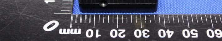
41 Appendix B: Photographs of EUT Product: Modem 915MHz v4.95 Model: 915MHz External Photos Page 41 of 45


42 Page 42 of 45


43 Page 43 of 45
44 Product: Modem 915MHz v4.95 Model: 915MHz Internal Photos Page 44 of 45
45 *****END OF REPORT***** Page 45 of 45
TEST REPORT. Issued for: ShenZhen MYGT Co.,LTD D3 Tongfuyu Industrial Area Community of Shajing Town, Baoan, Shenzhen, China.
 TEST REPORT FCC ID: 2AMKEMY-C11 Product: Wireless Gamepad Model No.: MY-C11 Additional Model No.: TKGC01 Trade Mark: N/A Issued Date: Oct. 16, 2017 Issued for: ShenZhen MYGT Co.,LTD D3 Tongfuyu Industrial
TEST REPORT. Issued for: RUIMA INTERNATIONAL(HK)INDUSTRIAL CO.,LIMITED NO.19 Ruixiang Road, Xinhua Industrial Zone, Huadu District, Guangzhou China
INDUSTRIAL CO.,LIMITED NO.19 Ruixiang Road, Xinhua Industrial Zone, Huadu District, Guangzhou China") TEST REPORT FCC ID: 2AHSJRM-626B Product: Boombox Speaker Model No.: RM-626 Additional Model: STREET HOPPER 6, CANNON 6 Trade Mark: RUIMA Issued Date: Aug. 04, 2016 Issued for: RUIMA INTERNATIONAL(HK)INDUSTRIAL
TEST REPORT FCC ID: 2AHSJRM-626B Product: Boombox Speaker Model No.: RM-626 Additional Model: STREET HOPPER 6, CANNON 6 Trade Mark: RUIMA Issued Date: Aug. 04, 2016 Issued for: RUIMA INTERNATIONAL(HK)INDUSTRIAL
TEST REPORT. Issued for: TICATAG 4 rue Louis de Broglie LANNION FRANCE. Issued By:
 TEST REPORT FCC ID: 2ANX5TIBE Product: Bluetooth Tracker Model No.: Tibe connect Additional Model No.: N/A Trade Mark: N/A Report No.: TCT171018E015 Issued Date: Oct. 27, 2017 Issued for: TICATAG 4 rue
TEST REPORT. Issued for:
 TEST REPORT FCC ID: 2ALPZ- AA00277W Product: Handsfree car kit with FM Transmitter Model No.: AA00277W Additional Model: AA00277G Trade Mark: N/A Report No.: TCT170331E007 Issued Date: Apr. 14, 2017 Issued
TEST REPORT. Issued for: SHENZHEN HAYNIE TECHNOLOGY CO., LTD 6TH FLOOR, EAST PART, CAO WEI 1ST INDUSTRIAL AREA, XIXIANG, BAO AN, SHENZHEN, China
 TEST REPORT FCC ID: 2AITSHAYNIE Product: BLUETOOTH SPEAKER Model No.: PN-19 Additional Model: UN-01, UN-02, UN-03, UN-05, UN-06, UN-07, UN-08, UN-09, UN-11, UN-12, UN-13, UN-15, UN-16, UN-17, UN-18, UN-19,
TEST REPORT. Issued for: RUIMA INTERNATIONAL(HK)INDUSTRIAL CO.,LIMITED NO.19 Ruixiang Road, Xinhua Industrial Zone, Huadu District, Guangzhou China
INDUSTRIAL CO.,LIMITED NO.19 Ruixiang Road, Xinhua Industrial Zone, Huadu District, Guangzhou China") TEST REPORT FCC ID: HSJRM-66B Product: Boombox Speaker Model No.: RM-66 dditional Model: STREET HOPPER 6, CNNON 6 Trade Mark: RUIM Issued Date: ug. 4, 6 Issued for: RUIM INTERNTIONL(HK)INDUSTRIL CO.,LIMITED
TEST REPORT FCC ID: HSJRM-66B Product: Boombox Speaker Model No.: RM-66 dditional Model: STREET HOPPER 6, CNNON 6 Trade Mark: RUIM Issued Date: ug. 4, 6 Issued for: RUIM INTERNTIONL(HK)INDUSTRIL CO.,LIMITED
TEST REPORT. Issued for:
 TEST REPORT FCC ID: 2AG5B-WD03 Product: WiFi hotspot + Power bank Model No.: WD03 Additional Model No.: MIFI 3G MOBILE WIFI ROUTER Trade Mark: Unitone/alldayinternet/wolder/ekko/HTM Report No.: TCT151225E011
TEST REPORT. Issued for:
 TEST REPORT FCC ID: 2ACJAPLT76XXG Product: TABLET PC Model No.: PLT7650G, PLT7649G, PLT76XXG ( XX can be replaced by digital from 00 to 99 ) Trade mark: N/A Report No.: TCT150721E012 Issued Date: Aug.
Page 1 of 51 Report No.: T TEST REPORT FCC ID: 2AGJ5WAP-30. In Accordance with: FCC PART 15, SUBPART C : 2015 (Section 15.
 Page 1 of 51 Report No.: T1851663 01 TEST REPORT FCC ID: 2AGJ5WAP-30 Applicant Address : Gonsin Conference Equipment Co., Ltd : No.401-406,Block C, Idea Industry Park, No.41 Fengxiang Road, Shunde, Foshan,
Revision history. Revision Date of issue Test report No. Description KES-RF-14T0042 Initial
 Page (2 ) of (34) Revision history Revision Date of issue Test report No. Description - 2014.08.25 Initial Page (3 ) of (34) TABLE OF CONTENTS 1. General information... 4 1.1. EUT description... 4 1.2.
Table of Contents 1. GENERAL INFORMATION SYSTEM TEST CONFIGURATION CONDUCTED EMISSIONS TEST RADIATED EMISSION TEST...
 Table of Contents 1. GENERAL INFORMATION... 4 1.1 PRODUCT DESCRIPTION FOR EQUIPMENT UNDER TEST... 4 1.2 RELATED SUBMITTAL(S) / GRANT (S)... 7 1.3 TEST METHODOLOGY... 7 1.4 EQUIPMENT MODIFICATIONS... 7
FCC Verification TEST REPORT
 FCC Verification TEST REPORT Product: 5 in 1 Environment Meter Model no.: ET-965 Trade Mark: N/A Report No.: TCT140915E005 Issued Date: Sep. 22, 2014 Issued for: Shenzhen Flus Technology Co., Ltd 3rd Floor,
FCC ID: B4OCC264BPA-S
 FCC TEST REPORT FCC ID: B4OCC264BPA-S Product : Bluetooth LE Module Model Name : CC264BPA-S, CC265BPA-S, CC26xBPA Brand : GT-tronics Report No. : PTC801181160622E-FC01 Prepared for GT-tronics HK Ltd Unit
TEST REPORT FCC ID: 2ADMF-HC06. : bluetooth module keyes HC-06, keyes hc-05, FUNDUINO HC-06, FUNDUINO hc-05
 Shenzhen Certification Technology Service Co., Ltd. 2F, Building B, East Area of Nanchang Second Industrial Zone, Gushu 2 nd Road, Bao'an District, Shenzhen 518126, P.R. China TEST REPORT FCC ID: 2ADMF-HC06
FCC REPORT. 570 E1 Camino Real #200, Redwood City, CA 94063, United Manufacturer:
 FCC REPORT Applicant: Address of Applicant: Manufacturer: Striiv Inc. 570 E1 Camino Real #200, Redwood City, CA 94063, United States Striiv Inc. Address of 570 E1 Camino Real #200, Redwood City, CA 94063,
FCC REPORT. Dongguan Hele Electronics Co.,Ltd. * In the configuration tested, the EUT complied with the standards specified above.
 Report No.: GTS201708000040F02 FCC REPORT Applicant: Address of Applicant: Manufacturer: Dongguan Hele Electronics Co.,Ltd. Dalingya Industrial Zone,Daojiao Town,Dongguan City,Guangdong,China Dongguan
FCC REPORT. Dongguan Hele Electronics Co.,Ltd. * In the configuration tested, the EUT complied with the standards specified above.
 + Applicant: Address of Applicant: Manufacturer: FCC REPORT Dongguan Hele Electronics Co.,Ltd. Report No.: GTS201708000040F01 Dalingya Industrial Zone,Daojiao Town,Dongguan City,Guangdong,China Dongguan
FCC REPORT. Dongguan Hele Electronics Co., Ltd. J11, J12, J13, Q7, Q28, Q26, Q29
 FCC REPORT Applicant: Dongguan Hele Electronics Co., Ltd. Address of Applicant: Dalingya Industrial Zone, Daojiao Town, Dongguan City, Guangdong China Equipment Under Test (EUT) Product Name: Model No.:
FCC CERTIFICATION TEST REPORT
 Report No:DDT-RE120176 Issued Date: 2013/01/05 FCC CERTIFICATION TEST REPORT FOR Applicant : AliMed Inc. Address : 297 High St Dedham Ma 02026 Equipment under Test : Alert transmitter Model No : #712716
7. Transmitter Radiated Spurious Emissions and Conducted Spurious Emission
 7. Transmitter Radiated Spurious Emissions and Conducted Spurious Emission 7.1 Test Setup Refer to the APPENDIX I. 7.2 Limit According to 15.247(d), in any 100 khz bandwidth outside the frequency band
TABLE OF CONTENTS 1. GENERAL INFORMATION... 4
 TABLE OF CONTENTS 1. GENERAL INFORMATION... 4 1.1. EUT DESCRIPTION... 4 1.2. TEST STANDARDS AND RESULTS... 5 1.3. FACILITIES AND ACCREDITATIONS... 6 1.3.1. FACILITIES... 6 1.3.2. TEST ENVIRONMENT CONDITIONS...
FCC PART TEST REPORT. Weccan Industrial Limited
 FCC PART 15.249 TEST REPORT For Weccan Industrial Limited Rm209, 2/F, Building W1-A, No.34 Gaoxin South 4th St Hi-Tech Industrial Park, Nanshan District, Shenzhen China FCC ID: Z3CWECCANDRONE Report Type:
REPORT REVISION HISTORY...
 Reference No.: WTS17S0579239E Page 2 of 39 2 Contents Page 1 COVER PAGE... 1 2 CONTENTS... 2 3 REPORT REVISION HISTORY... 3 4 GENERAL INFORMATION... 4 4.1 GENERAL DESCRIPTION OF E.U.T.... 4 4.2 DETAILS
FCC REPORT. 2AKQO-Q740 FCC CFR Title 47 Part 15 Subpart C. * In the configuration tested, the EUT complied with the standards specified above.
 FCC REPORT Applicant: Address of Applicant: Manufacturer/Factory: Address of Manufacturer/Factory: Guangzhou Smamao Electronic Technology Co.,Ltd Room 811, Building 8, No.315, Central City, Middle Road,
Shenzhen Hong Puya Technology Co., Ltd.
 Shenzhen United Testing Technology Co., Ltd. Report No.: UNI-1410102-01 FCC TEST REPORT Prepared For : Product Name: Model : Prepared By : Shenzhen Hong Puya Technology Co., Ltd. Bluetooth stereo4.0 S7720;
FCC REPORT. Lightcomm Technology Co., Ltd.
 FCC REPORT Report No.: GTS201608000267E01 Applicant: Lightcomm Technology Co., Ltd. Address of Applicant: RM 1808 18/F FO TAN INDUSTRIAL CENTRE NOS. 26-28 AU PUI WAN STREET FO TAN SHATIN NEW TERRITORIES
FCC Part 15B Measurement and Test Report. For. GlobTek, Inc. 186 Veterans Dr. Northvale, NJ USA. FCC Part 15 Subpart B.
 Test Standards: FCC Part 15B Measurement and Test Report Product Description: Tested Model: Report No.: For GlobTek, Inc. 186 Veterans Dr. Northvale, NJ 07647 USA FCC Part 15 Subpart B Power Supply GT-93020-0324
Pass* * In the configuration tested, the EUT complied with the standards specified above.
 No. 1 Workshop, M-10, Middle section, Science & Technology Park, Shenzhen, Guangdong, China 518057 Telephone: +86 (0) 755 2601 2053 Fax: +86 (0) 755 2671 0594 Email: ee.shenzhen@sgs.com Page: 1 of 41 Application
TEST REPORT. Reference No... : WTS16S E FCC ID... : SJ8-UDR777HD. Applicant... : RDI Technology Shenzhen Co., Ltd.
 TEST REPORT Reference No.... : WTS16S0449305E FCC ID... : SJ8-UDR777HD Applicant... : RDI Technology Shenzhen Co., Ltd. Address... : Building C1, Xintang Industrial Park East Baishixia, Fuyong, Baoan,
TEST REPORT. Shenzhen, PRC.
 TEST REPORT Reference No.... : WTS16S0449309E FCC ID... : SJ8-UDRC57 Applicant... : RDI Technology Shenzhen Co., Ltd. Address... : Building C1, Xintang Industrial Park East Baishixia, Fuyong, Baoan, Shenzhen,
FCC TEST REPORT. For EASYACC TECHNOLOGY CO., LIMITED Wireless speaker
 FCC ID: 2AJUJ-DP300 Page1 of 46 Report No.: R0217060058W FCC TEST REPORT For EASYACC TECHNOLOGY CO., LIMITED Wireless speaker Model No.: DP300 Prepared For : EASYACC TECHNOLOGY CO., LIMITED Address : UNIT
TEST REPORT. Issued for:
 TEST REPORT FCC ID: 2ALGRPLX-XWV70 Product: Cell phone signal booster Model No.: PLX-XWV70 Additional Model No.: PLX-XWV70, PLX-XWV70A Trade Mark: N/A Report No.: TCT170321E005 Issued Date: Apr. 24, 2017
TEST REPORT SZEM CR
 No. 1 Workshop, M-10, Middle section, Science & Technology Park, Shenzhen, Guangdong, China 518057 Telephone: +86 (0) 755 2601 2053 Fax: +86 (0) 755 2671 0594 Email: ee.shenzhen@sgs.com Application No.:
FCC ID: 2ALT5-GW6088
 TEST REPORT FCC ID: 2ALT5-GW6088 For GREAT WORLD LTD Electric Heater Model No. : GW-6078TBT, GW-6088TBT, GW-5088C-AMBT, GW-6088TMBT Trade Name : N/A Prepared for : Address : GREAT WORLD LTD 406 Room 1,
TRANSMITTER MODEL: KAS-2030M
 Page 1 of 16 FCC PART 15, SUBPART B and C TEST REPORT for TRANSMITTER MODEL: KAS-2030M Prepared for WILDLIFE TECHNOLOGIES 115 WOLCOTT STREET MANCHESTER, NEW HAMPSHIRE 03103 Prepared by: KYLE FUJIMOTO Approved
FCC Test Report. Report No.: PTCDQ FC01
 Page 1 of 63 FCC Test Report Report No.: PTCDQ04170450501-FC01 FCC ID : 2AL2XW801 APPLICATION PURPOSE : Original Equipment PRODUCT DESIGNATION : WIFI DoorBell BRAND NAME : EASTIC MODEL NAME : W801, W802,
APPLICATION FOR CERTIFICATION On Behalf of Futaba Corporation Radio Control Model No.:T10CG-2.4G FCC ID:AZPT10CG-24G Brand : Futaba
 FCC ID. AZPT10CG-24G Page 1 of 56 APPLICATION FOR CERTIFICATION On Behalf of Futaba Corporation Radio Control Model No.:T10CG-2.4G FCC ID:AZPT10CG-24G Brand : Futaba Prepared for : Futaba Corporation 1080
TEST REPORT : 2AIB7MGS. TEST DATE : to
 TEST REPORT APPLICANT : Hohem Technology Co.,Ltd PRODUCT NAME : 3-Axis Stabilizing Gimbal for Smartphone MODEL NAME BRAND NAME FCC ID STANDARD(S) : isteady Mobile : Hohem : 2AIB7MGS : 47 CFR Part 15 Subpart
FCC 47 CFR PART 15 SUBPART C CERTIFICATION TEST REPORT FOR. Bluetooth Remote Control for Video Set Top Box MODEL NUMBER: IPRC1000 FCC ID: 2ABTE-L3YJC9
 FCC 47 CFR PART 15 SUBPART C CERTIFICATION TEST REPORT FOR Bluetooth Remote Control for Video Set Top Box MODEL NUMBER: IPRC1000 REPORT NUMBER: 15U22448-E1V4 ISSUE DATE: 3/7/2016 Prepared for Verizon Online
FCC PART MEASUREMENT AND TEST REPORT FOR. Guangzhou Walkera Technology CO., LTD
 FCC PART 15.249 MEASUREMENT AND TEST REPORT FOR Guangzhou Walkera Technology CO., LTD Taishi Industrial Park, Yuwoto Town, Panyu District, 511475 Guangzhou, China. FCC ID: S29WK-2801PRO Report Concerns:
For. Tzone FCC ID: FCC Part Description: Product TZ-BT04. Report to Tested By: Manager STR I
 FCCC Part 15C Measurement and Test For Report Tzone Digitall Technology Co.., LTD 16D, Haiying Building, South of Caitian Road, Futiann District, Shenzhen China FCC ID: 2AKSQTZBT04 FCC Rule(s): Product
FCC Part 15C Test Report
 FCC Part 15C Test Report FCC ID: 2AL5W-DFIT Product Name: Trademark: Model Name : Prepared For : Address : Prepared By : smart watch N/A Dfit D8, D8S, D21, DF23, DF30, DB01, DB02, DB03, DB04, DB05, DB06,
FCC CFR47 PART 15 SUBPART C INDUSTRY CANADA RSS-GEN AND RSS-210 CERTIFICATION TEST REPORT FOR BROADCOM BLUETOOTH MODULE MODEL NUMBER: BCM92046MD
 FCC CFR47 PART 15 SUBPART C INDUSTRY CANADA RSS-GEN AND RSS-210 CERTIFICATION TEST REPORT FOR BROADCOM BLUETOOTH MODULE MODEL NUMBER: BCM92046MD IC #: 4324A-BRCM1029 REPORT NUMBER: 07U11199-1C ISSUE DATE:
FCC & RSS-216 (Class II Permissive Change) Wireless Power Transfer Report. for A Acer Incorporated
 Wireless Power Transfer Report. for A Acer Incorporated") Page 1 of 17 FCC 15.209 & RSS-216 (Class II Permissive Change) Wireless Power Transfer Report for A Acer Incorporated 8F., No.88, Sec. 1, Xintai 5th Rd., Xizhi, New Taipei City 22181, Taiwan (R.O.C) Product
Page 1 of 17 FCC 15.209 & RSS-216 (Class II Permissive Change) Wireless Power Transfer Report for A Acer Incorporated 8F., No.88, Sec. 1, Xintai 5th Rd., Xizhi, New Taipei City 22181, Taiwan (R.O.C) Product
ITL Page 2 of 71 Report No.:
 ITL Page 1 of 71 Report No.: 12092752 TEST REPORT Applicant: Address of Applicant: Harman International Industries, Incorporated 8500 Balboa Blvd, Northridge, CA 91329, United States Manufacturer: Address
Jul. 16, Jun. 04, Shenzhen. Tel:(86-755)
") Test Report FCC ID.: MTi160413E004 Date of issue: Jul. 16, 2016 Sample Description: Wireless POS Terminal Model(s): G3 Applicant: Shenzhen Xinguodu Technology Co., Ltd. Address: 17/A, Jinsong Building
Test Report FCC ID.: MTi160413E004 Date of issue: Jul. 16, 2016 Sample Description: Wireless POS Terminal Model(s): G3 Applicant: Shenzhen Xinguodu Technology Co., Ltd. Address: 17/A, Jinsong Building
FCC & IC TEST REPORT for Bluetooth Device No SHA-001
 Page 1 of 41 FCC & IC TEST REPORT for Bluetooth Device No. 161100632SHA-001 Applicant : Manufacturer : Product Name : SHENZHEN DNS INDUSTRIES CO., LTD. 23/F Building A, Shenzhen International Innovation
For. Unit D16/F. should not use it to claim FCC ID: 2AAIN-MNGLOS
 Page 1 of 49 TESTT REPORT For Applicant : ACOUSTMAX INTERNATIONAL CO.., LTD Unit D16/F Cheuk Nang Plaza 250 Hennessy Road Address : WanchaiHongKong Product Name : Monster GLO Model Name : MNGLO-S, MNGLO-L,MNGLO-M,MNGLO-Mini
Shenzhen Hong Puya Technology Co., Ltd.
 FCC TEST REPORT Prepared For : Product Name: Model : Prepared By : Shenzhen Hong Puya Technology Co., Ltd. Bluetooth stereo4.0 S7720; S111; S222; S7730; S777 Shenzhen United Testing Technology Co., Ltd.
FCC PART 15C TEST REPORT FOR CERTIFICATION On Behalf of. DEI Sales Inc. dba Definitive Technology. Model Number: STUDIO SLIM SUBWOOFER
 FCC PART 15C TEST REPORT FOR CERTIFICATION On Behalf of DEI Sales Inc. dba Definitive Technology 3.1 Home Theater Sound Bar and Wireless Subwoofer System Model Number: STUDIO SLIM SUBWOOFER FCC ID: IPUSTUSLIMSUB
FCC Test Report. Report No.: AGC FE03. MODEL NAME : Ci3, Ti3, CB3, AO, UI, Vinyl I, Vinyl B, M2
 Page 1 of 51 FCC Test Report FCC ID : VO8CI3 APPLICATION PURPOSE : Original Equipment PRODUCT DESIGNATION : Bluetooth headset BRAND NAME : Bluedio MODEL NAME : Ci3, Ti3, CB3, AO, UI, Vinyl I, Vinyl B,
No. 620 HuaYuan Commercial Center, No. 347 XiXiang Road,XiXiang Town, Bao An District, ShenZhen City Tel : Fax:
 No. 620 HuaYuan Commercial Center, No. 347 XiXiang Road,XiXiang Town, Bao An District, ShenZhen City Tel : +86-755-27912080 Fax: +86-755-27916936 FCC TEST REPORT Product name : 7PORT DUAL SUPPLY POE SWITCH
FCC TEST REPORT. ADDRESS: #2 Creation Rd. 4, Science-Based Ind. Park Hsinchu Taiwan, R.O.C.
 FCC TEST REPORT REPORT NO.: RF991014E04 MODEL NO.: M-R0018 FCC ID: JNZMR0018 RECEIVED: Oct. 14, 2010 TESTED: Oct. 19, 2010 ISSUED: Oct. 22, 2010 APPLICANT: LOGITECH FAR EAST LTD. ADDRESS: #2 Creation Rd.
Description of Test Facility
 Description of Test Facility Name: Address: Intertek Testing Services Limited Shanghai Building No.86, 1198 Qinzhou Road(North), Shanghai 200233, P.R. China FCC Registration Number: 236597 IC Assigned
FCC AND IC CERTIFICATION TEST REPORT
 Issued Date: Mar. 8, 205 FCC AND IC CERTIFICATION TEST REPORT FOR Applicant : Harman International Industries, Incorporated Address : 8500 Balboa Blvd, Northridge, CA 9329, UNITED STATES Equipment under
Report No.: TRE Page: 21 of 40 Issued: No Plot 8DPSK - Report Template Version: H00 ( )
") Report No.: TRE1705022404 Page: 21 of 40 Issued: 2017-06-20 GFSK π/4dqpsk No Plot 8DPSK - Report No.: TRE1705022404 Page: 22 of 40 Issued: 2017-06-20 5.6. Hopping Channel Number LIMIT FCC CFR Title 47
Report No.: TRE1705022404 Page: 21 of 40 Issued: 2017-06-20 GFSK π/4dqpsk No Plot 8DPSK - Report No.: TRE1705022404 Page: 22 of 40 Issued: 2017-06-20 5.6. Hopping Channel Number LIMIT FCC CFR Title 47
Title: Test on 5.8 GHz Band Outdoor WiFi (802.11b/g) Wireless Base Station
 Wireless Base Station") Page 20 of 51 Pages 7.5. Conducted spurious emission 7.5.1. Requirements: Clause 15.247(d). In any 100 khz bandwidth outside the frequency band in which the spread spectrum or digitally modulated intentional
Page 20 of 51 Pages 7.5. Conducted spurious emission 7.5.1. Requirements: Clause 15.247(d). In any 100 khz bandwidth outside the frequency band in which the spread spectrum or digitally modulated intentional
FCC PART 15C TEST REPORT FOR CERTIFICATION On Behalf of. Trade Name : Activision. Model Number: / FCC ID: XLU
 FCC PART 15C TEST REPORT FOR CERTIFICATION On Behalf of Activision Publishing, Inc USB Wireless Receiver for Wii & USB Wireless Receiver for PS3 Trade Name : Activision. Model Number: 83973791/84148791
FCC Test Report. Report No.: AGC FE03. : Shenzhen Liangzi Zhineng Technology Co., Ltd. Attestation of Global Compliance (Shenzhen) Co.
 Co.") Page 1 of 70 FCC Test Report Report No.: AGC06913160501FE03 FCC ID APPLICATION PURPOSE PRODUCT DESIGNATION BRAND NAME : 2AIM7JAZZ6 : Original Equipment : Bluetooth Headset : BlueFit, Kavoxii MODEL NAME
Page 1 of 70 FCC Test Report Report No.: AGC06913160501FE03 FCC ID APPLICATION PURPOSE PRODUCT DESIGNATION BRAND NAME : 2AIM7JAZZ6 : Original Equipment : Bluetooth Headset : BlueFit, Kavoxii MODEL NAME
HID GLOBAL CORPORATION
 HID GLOBAL CORPORATION RFID READER, OPERATING ON 125 KHZ AND 13.56 MHZ Model: ERP40C 12 January 2010 Report No.: SL09050401-HID-011_ERP40C (15.225 & RSS-210) (This report supersedes None)) Modifications
FCC PART MEASUREMENT AND TEST REPORT
 FCC PART 15.109 MEASUREMENT AND TEST REPORT FOR ThinNetworks IT products Limited SAAN 02 #260- Industrial Zone Brasilia- DF, Brazil- 70.632-200 FCC ID: WQ3CF-000585 Report Concerns: Original Report Equipment
RADIO TEST REPORT. For Shenzhen ZD Intelligent Technology Co., Ltd.
 RADIO TEST REPORT For Shenzhen ZD Intelligent Technology Co., Ltd. Product Name: WIFI Camera Model : WXHI130W-V11 WXHI100W-V8 WXHI100W-V9 WXHI100W-V10 ZD-CHI130B-F3 Series Model: ZD-HGM130B-F2 ZD-CHI130B-F4
FCC PART 15C TEST REPORT FOR CERTIFICATION On Behalf of. Sony Corporation. Wireless Speaker SRS-XB10 FCC ID: AK8SRSXB10
 FCC ID: AK8SRSXB10 FCC PART 15C TEST REPORT FOR CERTIFICATION On Behalf of Sony Corporation Wireless Speaker SRS-XB10 FCC ID: AK8SRSXB10 Prepared for : Sony Corporation 1-7-1 Konan Minato-ku Tokyo, 108-0075
FCC C2PC Test Report
 FCC C2PC Test Report FCC ID Equipment Model No. Brand Name Applicant : SQGBT800 : BTv4.0 Dual Mode USB Dongle : BT820 : Laird Technologies : Laird Technologies Address : 11160 Thompson Ave. / Lenexa, Kansas
King Pigeon Communication Co., Limited
 APPLICATION FOR ELECTROMAGNETIC COMPATIBILITY DIRECTIVE On Behalf of King Pigeon Communication Co., Limited Remote Controller RTU Model No.: S130, S140, S150, S180, S25x, S26x, S27x, RTU501x, RTU502x,
Test Report. Applicant ASUSTeK COMPUTER INC. 4F, No. 150, Li-Te Rd., Peitou, Taipei, Taiwan. Date of Receipt Jan. 28, Issued Date Mar.
 Test Report Product Name Model No. FCC ID. IC ID. WPC Qi 1.1/1.0 compliance wireless charging micro-usb box Wireless Charger MSQ-ASUSWLCHARGER 3568A-ASWLCHARGER Applicant ASUSTeK COMPUTER INC. Address
Version TEST REPORT NO. DATE DESCRIPTION
 Version NO. DATE DESCRIPTION HCTR1302FR13 February 14, 2013 - First Approval Report - Additional Model Name Page 2 of 25 Table of Contents 1. GENERAL INFORMATION... 4 2. EUT DESCRIPTION... 4 3. TEST METHODOLOGY...
OUTDOOR SOUND MODULE/TRANSMITTER MODEL: THE BANDIT
 Page 1 of 16 FCC PART 15, SUBPART B and C TEST REPORT for OUTDOOR SOUND MODULE/TRANSMITTER MODEL: THE BANDIT Prepared for MINASKA OUTDOORS 6517 PLATTE AVENUE LINCOLN, NEBRASKA 68507 Prepared by: KYLE FUJIMOTO
Pico 900MHz 1W FHSS Module Model: p900 FCC ID: NS913P900. Applicant:
 Pico 900MHz 1W FHSS Module Model: p900 Applicant: Microhard Systems Inc. 150 Country Hills Landing NW Calgary, Alberta Canada T3K 5P3 In Accordance With Federal Communications Commission (FCC) Part 15,
FCC 15B Test Report. : BTv4.0 Dual Mode USB Dongle. Address : Thompson Ave. / Lenexa, Kansas / / USA
 FCC 15B Test Report Equipment Model No. Brand Name Applicant : BTv4.0 Dual Mode USB Dongle : BT820 : Laird Technologies : Laird Technologies Address : 11160 Thompson Ave. / Lenexa, Kansas / 66219 / USA
FCC 47 CFR PART 15 SUBPART C INDUSTRY CANADA RSS-210 ISSUE 8 BLUETOOTH LOW ENERGY CERTIFICATION TEST REPORT FOR. 2.4GHz LE MODULE MODEL NUMBER: RN4020
 FCC 47 CFR PART 15 SUBPART C INDUSTRY CANADA RSS-210 ISSUE 8 BLUETOOTH LOW ENERGY CERTIFICATION TEST REPORT FOR 2.4GHz LE MODULE MODEL NUMBER: RN4020 REPORT NUMBER: 14U17191-1 ISSUE DATE: MARCH 21, 2014
FCC Part 15C Test Report FCC ID: 2ANYRCBAR-25
 FCC Part 15C Test Report FCC ID: 2ANYRCBAR-25 Product Name: Bluetooth Module Trademark: Model Name : Prepared For : Address : CBAR-25 PT. Eyro Digital Teknologi Jl, Amir Mahmud IX/23 Gunung Anyar, Surabaya
FCC Test Report. Report No.: AGC FE02 CLIENT : INNOVATIVE CONCEPTS AND DESIGN LLC. Attestation of Global Compliance (Shenzhen) Co., Ltd.
 Co., Ltd.") Page 1 of 43 FCC Test Report Report No.: AGC03588150607FE02 FCC ID : 2AE6GUHF 6000HHM APPLICATION PURPOSE : ORIGINAL EQUIPMENT PRODUCT DESIGNATION : Wireless Microphone BRAND NAME : Gemini MODEL NAME :
Page 1 of 43 FCC Test Report Report No.: AGC03588150607FE02 FCC ID : 2AE6GUHF 6000HHM APPLICATION PURPOSE : ORIGINAL EQUIPMENT PRODUCT DESIGNATION : Wireless Microphone BRAND NAME : Gemini MODEL NAME :
TEST REPORT. For. Model Name : Maestro T4HU1608, Maestro T4HUXXXX (X is 0 to 9) Issued by : Most Technology Service Co., Limited.
 Issued by : Most Technology Service Co., Limited.") TEST REPORT For Applicant : Address : Product Name : Tech4home, Lda Rua de Fundoes, No.151, 3700-121 Sao Joao da Madeira, Portugal Remote Control Unit Model Name : Maestro T4HU1608, Maestro T4HUXXXX (X
TEST REPORT For Applicant : Address : Product Name : Tech4home, Lda Rua de Fundoes, No.151, 3700-121 Sao Joao da Madeira, Portugal Remote Control Unit Model Name : Maestro T4HU1608, Maestro T4HUXXXX (X
Report Number: F690501/RF-RTL Page : 2 of 48 INDEX
 Report Number: F690501/RF-RTL007686-1 Page : 2 of 48 INDEX Table of Contents Page 1. General Information --------------------------------------------------------------------------------- 3 2. Transmitter
Table of Contents 1. GENERAL INFORMATION SYSTEM TEST CONFIGURATION CONDUCTED EMISSIONS TEST... 12
 Table of Contents 1. GENERAL INFORMATION... 5 1.1 PRODUCT DESCRIPTION FOR EQUIPMENT UNDER TEST... 5 1.2 RELATED SUBMITTAL(S) / GRANT (S)... 8 1.3 TEST METHODOLOGY... 8 1.4 EQUIPMENT MODIFICATIONS... 8
FCC PART 15 SUBPART C TEST REPORT FCC PART
 FCC PART 15 SUBPART C TEST REPORT FCC PART 15.249 Shenzhen CTL Testing Technology Co., Ltd. Tel: +86-755-89486194 Fax: +86-755-26636041 Report Reference No.: CTL1508212421-WF Compiled by: ( position+printed
FCC TEST REPORT. For Shenzhen Qinps Technology Co., Ltd Soundcircularbluetooth speaker
 FCC ID: 2ANLQ-BTSC001 Page 1 of 61 Report No.: R0217080079W1 FCC TEST REPORT For Shenzhen Qinps Technology Co., Ltd Soundcircularbluetooth speaker Model No.: BTSC001, BTSC Prepared For : Shenzhen Qinps
FCC Part 15C Test Report FCC ID: 2AK8V-WF8300
 FCC Part 15C Test Report FCC ID: 2AK8V-WF8300 Product Name: Trademark: USB type wireless WIFI signal amplifier N/A Model Name : WF8300 Prepared For : Address : Shenzhen Elicks Technology Co., Ltd. No.18
FCC PART TEST REPORT BEYOND RADIO TECHNOLOGY LIMITED
 FCC PART 15.247 TEST REPORT For BEYOND RADIO TECHNOLOGY LIMITED Room 11, 20/F, Grandtech Centre No.8 On Ping Street Shatin, NT, Hong Kong FCC ID: 2AFV9FX100SERIES Report Type: Original Report Product Type:
Report No.: BST Y ER 2 RADIO TEST REPORT. For Shenzhen sinocam Technology Co.,LTD.
 RADIO TEST REPORT For Shenzhen sinocam Technology Co.,LTD. Product Name: WIFI IP CAMERA Model : Series Model: FCC ID: SN IPC HW01 SN IPC HW01, SN IPC HW02, SN IPC HW03, SN IPC HW04, SN IPC HW05, SN IPC
TEST REPORT. For RFID READER/WRITER. In conformity with. FCC CFR 47 Part15 Subpart C
 TEST REPORT For RFID READER/WRITER In conformity with FCC CFR 47 Part15 Subpart C Model: TR3XM-SD01 / TR3XM-SU01 / TR3XM-SN01 FCC ID: MK4TR3XM-SX01 Test Item: RFID READER/WRITER Report No: RY1203Z12R1
Report Number: F690501/RF-RTL Page: 2 of 72 INDEX
 Report Number: F690501/RF-RTL007164-1 Page: 2 of 72 INDEX Table of Contents Page 1. General Information --------------------------------------------------------------------------------- 3 2. Transmitter
Report Number : F690501/RF-RTL Page: 2 of 62
 Report Number : F690501/RF-RTL011830-1 Page: 2 of 62 Table of Contents Page 1. General Information --------------------------------------------------------------------------------- 3 2. Transmitter Radiated
EMC Test Report. Tested by: Jeremy O. Pickens, Senior EMC Engineer. Reviewed by: David Schramm, EMC/RF/SAR/HAC Manager
 Page: 1 of 24 EMC Test Report Project Number: 4104971 Report Number: 4104971EMC01 Revision Level: 0 Client: Tier One, Inc. Equipment Under Test: GEN4 Glock Sensor Model Number: BA10232 FCC ID: 2AJ3810232
FCC PART 15C TEST REPORT FOR CERTIFICATION On Behalf of. ION Audio, LLC. Portable Karaoke PA speaker with vocal effects
 FCC PART 15C TEST REPORT FOR CERTIFICATION Behalf of ION Audio, LLC Portable Karaoke PA speaker with vocal effects Model Number: ipk3 KARAOKE STAR PLUS FCC ID: 2AB3E-IPK3 Prepared for: Prepared By: ION
FCC ID: 2AAYYBM1. Equipment Type: Outdoor Bluetooth speaker. This Report Concerns: Original Report
 FCC PART 15.249 EMI MEASUREMENT AND TEST REPORT For shenzhen Aicheng Technology Co.,Ltd Unit 1202, West Tower, Nanshan Digital Culture Industrial Base,Nan Shan District, Shenzhen, Guangdong, China September
Ave output power ANT 1(dBm) Ave output power ANT 2 (dbm)
 Ave output power ANT 2 (dbm)") Page 41 of 103 9.6. Test Result The test was performed with 802.11b Channel Frequency (MHz) power ANT 1(dBm) power ANT 2 (dbm) power ANT 1(mW) power ANT 2 (mw) Limits dbm / W Low 2412 7.20 7.37 5.248 5.458
Page 41 of 103 9.6. Test Result The test was performed with 802.11b Channel Frequency (MHz) power ANT 1(dBm) power ANT 2 (dbm) power ANT 1(mW) power ANT 2 (mw) Limits dbm / W Low 2412 7.20 7.37 5.248 5.458
TEST REPORT To: - ABO ELECTRONICS (SHENZHEN) CO., LTD Block B3, Haocheng Industrial Park, Hexiu West Rd, Heping Village, Fuyong, Baoan, Shenzhen
 CO., LTD Block B3, Haocheng Industrial Park, Hexiu West Rd, Heping Village, Fuyong, Baoan, Shenzhen") To: TEST REPORT No.: (5216)033-0360(A) PARTICLE INDUSTRIES, INC TEST REPORT To: - Attn: Eric Attn: - Address: 1400 Tennessee St, #4 San Francisco, CA Address: - 94107 Fax: -- Fax: - E-mail: -- E-mail:
To: TEST REPORT No.: (5216)033-0360(A) PARTICLE INDUSTRIES, INC TEST REPORT To: - Attn: Eric Attn: - Address: 1400 Tennessee St, #4 San Francisco, CA Address: - 94107 Fax: -- Fax: - E-mail: -- E-mail:
REVISION HISTORY. The revision history for this document is shown in table. HCT-EM-1801-FC037 January 22, 2018 Initial Release
 REVISION HISTORY The revision history for this document is shown in table. Version Issue Date Description HCT-EM-1801-FC037 January 22, 2018 Initial Release HCT-EM-1801-FC037-R1 January 26, 2018 Revision
FCC CFR47 PART 15 SUBPART C CERTIFICATION TEST REPORT FOR DUAL RADIO OUTDOOR ACCESS POINT MODEL NUMBER: AP-ONE FCC ID: SWX-AP1R2
 FCC CFR47 PART 15 SUBPART C CERTIFICATION TEST REPORT FOR DUAL RADIO OUTDOOR ACCESS POINT MODEL NUMBER: AP-ONE REPORT NUMBER: 04U3091-1 ISSUE DATE: JANUARY 07, 2005 Prepared for UBIQUITI NETWORKS 1111
TEST REPORT WTN16S E 2AFOYL654UCNN
 TEST REPORT Reference No.... : FCC ID... : Applicant... : Address... : Manufacturer... : Address... : Product Name... : Model No..... : Brand.... WTN16S0754892-1E 2AFOYL654UCNN Le Shi Zhi Xin Electronic
TEST REPORT. Building 6, XinXinTian Industrial Park, XinSha Road, ShaJing, Baoan District, ShenZhen, China. Shenzhen Innokin Technology Co.
 TEST REPORT Applicant Address Shenzhen Innokin Technology Co., Ltd Building 6, XinXinTian Industrial Park, XinSha Road, ShaJing, Baoan District, ShenZhen, China Manufacturer or Supplier Address Product
TEST REPORT FCC PART Jacky Chen (File administrators) Allen Wang (Test Engineer) Tracy Qi (Manager)
 Allen Wang (Test Engineer) Tracy Qi (Manager)") TEST REPORT FCC PART 15.249 Shenzhen CTL Testing Technology Co., Ltd. Tel: +86-755-89486194 Fax: +86-755-26636041 Report Reference No.... : CTL1606222365-WF Compiled by: ( position+printed name+signature)
TEST REPORT FCC PART 15.249 Shenzhen CTL Testing Technology Co., Ltd. Tel: +86-755-89486194 Fax: +86-755-26636041 Report Reference No.... : CTL1606222365-WF Compiled by: ( position+printed name+signature)
FCC PART 15C TEST REPORT FOR CERTIFICATION On Behalf of. Sony Corporation. Home Audio System GTK-XB90 FCC ID: AK8GTKXB90
 FCC ID:AK8GTKXB90 FCC PART 15C TEST REPORT FOR CERTIFICATION On Behalf of Sony Corporation Home Audio System GTK-XB90 FCC ID: AK8GTKXB90 Prepared for : Sony Corporation 1-7-1 Konan Minato-ku Tokyo, 108-0075
TEST REPORT To: - ABO ELECTRONICS (SHENZHEN) CO., LTD Block B3, Haocheng Industrial Park, Hexiu West Rd, Heping Village, Fuyong, Baoan, Shenzhen
 CO., LTD Block B3, Haocheng Industrial Park, Hexiu West Rd, Heping Village, Fuyong, Baoan, Shenzhen") To: TEST REPORT No.: (5216)033-0357(A) PARTICLE INDUSTRIES, INC TEST REPORT To: - Attn: Eric Attn: - Address: 1400 Tennessee St, #4 San Francisco, CA Address: - 94107 Fax: -- Fax: - E-mail: -- E-mail:
To: TEST REPORT No.: (5216)033-0357(A) PARTICLE INDUSTRIES, INC TEST REPORT To: - Attn: Eric Attn: - Address: 1400 Tennessee St, #4 San Francisco, CA Address: - 94107 Fax: -- Fax: - E-mail: -- E-mail:
FCC Test Report. Report No.: AGC FE04. Attestation of Global Compliance (Shenzhen) Co., Ltd
 Co., Ltd") Page 1 of 74 FCC Test Report Report No.: AGC07248170302FE04 FCC ID : TV7WBM APPLICATION PURPOSE : Original Equipment PRODUCT DESIGNATION : Woobm-USB BRAND NAME : N/A MODEL NAME : Woobm-USB CLIENT : Mikrotikls
Page 1 of 74 FCC Test Report Report No.: AGC07248170302FE04 FCC ID : TV7WBM APPLICATION PURPOSE : Original Equipment PRODUCT DESIGNATION : Woobm-USB BRAND NAME : N/A MODEL NAME : Woobm-USB CLIENT : Mikrotikls
1/41 IC: 109U-89FT7100
 SAMM No.0825 MOTOROLA PENANG ADV. COMM. LABORATORY FCC / IC TEST REPORT Motorola Solutions Malaysia Sdn. Bhd. Report Revision : Rev.A Innoplex Plot 2A Medan Bayan Lepas, Mukim 12, S.W.D. 11900 Bayan Lepas,
RF TEST REPORT for Intentional Radiator No SHA-001
 RF TEST REPORT for Intentional Radiator No. 160600514SHA-001 Applicant : Shanghai Ruipai Intelligent Technology Co.,Ltd. B105, Building 9, Wusong Science Park, No.69 Tieshan Rd., Baoshan District, Shanghai,
FCC PART TEST REPORT. invoixa
 FCC PART 15.247 TEST REPORT For invoixa 2 rue Maurice Hartman Issy-Les-Moulineaux France FCC ID: ZVS-KTP1 Report Type: Original Report Product Type: KTP1 Test Engineer: Mike Hu Report Number: RSZ150717005-00B