How it works... 3 Key features... 3 Specifications... 3
|
|
|
- Maximillian Ellis
- 5 years ago
- Views:
Transcription


1
2 How it works... 3 Key features... 3 Specifications... 3 Programming of user time for selected position... 5 Programming of max/min servo lever position... 5
3 RC F1H was designed to replace mechanical timers in free flight models. It was designed for F1H category. This electronic timer provides precise timing to activate dethermalization. For advance users each preset time can be preprogramed on field and also servo min/max position can be programmed. On RC F1H, there is a rotary switch with 16 positions. After power ON, servo lever goes to start (max) position, beeper makes a short beep and starts to count down time until it runs out. User can select one of pre-programmed times with rotation of rotary switch and that time will start to count down after reset button is pressed. Each time reset button is pressed, the count down time will reset and a short beep will be heard. Device will wait until reset button is released and then it will start count down again from beginning. After time out, servo lever goes to end (min) position and waits there until reset button is pressed. All that time beeper makes beeping sound for easier location of the plane if it is lost. When reset button is pressed, servo lever goes to start (max) position again and selected time starts to count down again. Small and lightweight at only 1 gram. 16 pre-programmed times. Precise timing. Low price. Low input current Onboard beeper for easier search of the plane. Board Dimensions Weight Input Current (without servo motor) Temperature Range 1 Input Voltage Range 15 mm x 8 mm x 7 mm 0.55 x 0.35 x gram ~5 milliamps, 55 milliamps when beeping -10 C ~ +60 C volts DC 1 Specifications are taken from component ratings and system limits and may not have been tested to the full extent of the specified ranges.


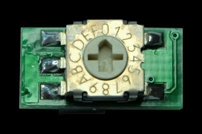
4 Figure 1 shows how to connect the RC F1H module. Figure 1: The RC F1H module. If not pre-programed by user, following times can be selected. 0: 15s 8: 140s 1: 30s 9: 180s 2: 50s A: 200s 3: 60s B: 240s 4: 80s C: 260s 5: 90s D: 300s 6: 110s E: 320s 7: 120s F: 360s
5 To enter programming mode, press and hold down reset button while powering the module ON. Three normal beeps will be heard indicating programming mode. If there is no operation for 2s, module will exit programming mode and will go into normal countdown mode. User has 2 different programming mode to select. To select them use reset button to change between modes. Mode is indicated with number of beeps: 1 normal beep: - programming of user time for selected position 2 normal beeps: programming of max/min servo lever position To enter specific programming mode just wait for 2s after number of beeps are heard. Enter into programming mode is indicated with 2 short beeps. To program new time for selected position on rotary switch, please select position on rotary switch first, then power on module and enter into the programming mode (hold down switch, power module on, press switch once and wait for 2s) Now enter new time simply as a result of A x B = time (in seconds). To enter new time of 15s you can select different options: 1 x 15, 3 x 5, 5 x 3, 15 x 1 With pressing of reset button, first A number is entered. Each press will indicate beep and will increase A number by 1. When you have finished entering number A wait for 2 s and 2 short beeps will indicate start of B number. After B number is entered, wait for 2s and a long 4s beep will indicate save of new time and exit from programming mode. Normal mode is active after that. If you do not wish to save new time simply turn off module before finishing with B number and old time will still be inside memory. To program new max/min servo position power on module and enter into the programming mode (hold down switch, power module on, press switch twice and wait for 2s) Now servo will go-to center position (1700us servo pulse) and with each press of reset button, servo pulse time will increase for 50us until 2200us is reached, then it will go to circle mode from 1500us 2200us. Changing servo pulse will change servo lever position. When user is happy with max position, wait for 2s and min position can be set the same way as max. On min position servo pulse time is being changed in range from 1500us 800us. Once finished, wait for 2s and long 4s beep will indicate save of new max/min and exit to normal mode. If you do not wish to save new servo lever positions simply turn off module before finishing with min position and old values will still remain in memory.
Height Limited Switch
 Height Limited Switch Manual version: 1.0 Content Introduction...3 How it works...3 Key features...3 Hardware...4 Motor cut-off settings...4 Specification...4 Using the RC HLS #1 module...5 Powering the
RC Altimeter #2 BASIC Altitude data recording and monitoring system 3/8/2009 Page 2 of 11
 Introduction... 3 How it works... 3 Key features... 3 System requirements... 3 Hardware... 4 Specifications... 4 Using the RC Altimeter #2 BASIC module... 5 Powering the module... 5 Mounting the module...
Rx62H Linear 5 Channel Brick
 Rx62H Linear 5 Channel Brick (DSM 2 Compatible) DOWN Elevator Servo MicronWings Website Features Product: DSM2 receiver with 2 onboard linear servos Channels: 5 Size: 23.0 x 24.0 x 8.0mm Weight: 3.48grams
Channel Remote Programming: For the (35R Motor with or without a Plug) LEFT SIDE AND RIGHT SIDE MOTORS
 LEFT SIDE AND RIGHT SIDE MOTORS") 2016 15 Channel Remote Programming: For the (35R Motor with or without a Plug) LEFT SIDE AND RIGHT SIDE MOTORS Right Side Worms FRONT REMOTE CONTROL BACK Left Side Worms Channel Display Up Stop Down Channel
2016 15 Channel Remote Programming: For the (35R Motor with or without a Plug) LEFT SIDE AND RIGHT SIDE MOTORS Right Side Worms FRONT REMOTE CONTROL BACK Left Side Worms Channel Display Up Stop Down Channel
Detrum GAVIN-8C Transmitter
 Motion RC Supplemental Guide for the Detrum GAVIN-8C Transmitter Version 1.0 Contents Review the Transmitter s Controls... 1 Review the Home Screen... 2 Power the Transmitter... 3 Calibrate the Transmitter...
The Smallest, Quietest & Safest Garage Door Operator in the World!
 ZAP Technical Instruction The Smallest, Quietest & Safest Garage Door Operator in the World! Function Programming Series controller applicable to: 800 II G, 800 II, 8800 II, 8800 II HP, 8850 These functions
DM-46 Instruction Manual
 Test Equipment Auto Meter Products Inc. 413 West Elm Street Sycamore, IL 60178 Service (815) 899-0801 Toll Free (866) 883-TEST (8378) www.autometer.com/test DM-46 Instruction Manual Automotive Multimeter
What to do if you buy a model with a Magic Timer. Preliminary Version 0.8
 What to do if you buy a model with a Magic Timer Preliminary Version 0.8 December 2012 Page 1 Table of Contents Page 2 1. Purpose The purpose of this document is to help people get started when they buy
Agilent U1273A/U1273AX Handheld Digital Multimeter. Quick Start Guide
 Agilent U1273A/U1273AX Handheld Digital Multimeter Quick Start Guide Verify that you received the following items in the shipment of your multimeter: One pair of red and black test leads One pair of 4
Wholesale Chess Basic Digital Chess Timer with Bonus and Delay. User Manual
 Wholesale Chess Basic Digital Chess Timer with Bonus and Delay User Manual [1] Wholesale Chess Basic Digital Chess Timer with Bonus and Delay The Wholesale Chess Basic Digital Timer with bonus and delay
MW3105 DIGITAL CLAMP MULTIMETER
 MW3105 DIGITAL CLAMP MULTIMETER 2 M MW3105 A 01 INTRODUCTION 1.1 - Unpacking and inspection Upon removing your new Digital Clamp Meter from its packing, you should have the following items: 1. Digital
Electrical Multimeter
 113 Electrical Multimeter Instruction Sheet Safety Information A Warning statement identifies hazardous conditions and actions that could cause bodily harm or death. A Caution statement identifies conditions
Blue Point Engineering
 Blue Point Engineering Instruction I www.bpesolutions.com Pointing the Way to Solutions! Puppet - II+ Controller (BPE No. PCA-0001) Servo Position Adjustment EEPROM Digital Button Power 5 Vdc Playback
TROUBLE SHOOTING FOR 1001-A SERIES REMOTES
 TROUBLE SHOOTING FOR 1001-A SERIES REMOTES is within the 20 25 range of the receiver. 1001-A 1001T/LCD-A &1001TH-A 1001-A Series Transmitter Battery location Transmitter Battery location Receiver Battery
ENGLISH Table of Contents
 ENGLISH Table of Contents DGT 3000 Display and buttons... 5 Introduction... 6 Timing methods... 6 Time... 6 Fischer Bonus... 7 US Delay... 7 Delay... 7 Byo-yomi... 7 Canadian Byo-yomi... 8 Upcount... 8
Robotic Navigation Distance Control Platform
 Robotic Navigation Distance Control Platform System Block Diagram Student: Scott Sendra Project Advisors: Dr. Schertz Dr. Malinowski Date: November 18, 2003 Objective The objective of the Robotic Navigation
TOP SERVO SIGNAL 5 SERVO SIGNAL 3 SERVO SIGNAL 4 SERVO SIGNAL 6 T B T B T B T B T B SERVO TRIGGER 1 BOTTOM
 Micro Miniatures Servo Controller Channel Location of connections and switches TOP SERVO SIGNAL SERVO SIGNAL 7 SERVO SIGNAL 6 SERVO SIGNAL 5 SERVO SIGNAL SERVO SIGNAL SERVO SIGNAL SERVO SIGNAL SIGNAL COMMON
Digital Multifunctional RC-Soundmodule TBS Mini V2
 Digital Multifunctional RC-Soundmodule TBS Mini V2 Important notes about changes on the NEW TBS Mini V2!!! MUST BE READ!!! New connector: External amplifier Volume Unchanged connectors (same as old TBS
Lab 8. Stepper Motor Controller
 Lab 8. Stepper Motor Controller Overview of this Session In this laboratory, you will learn: To continue to use an oscilloscope How to use a Step Motor driver chip. Introduction This lab is focused around
RC Servo Interface. Figure Bipolar amplifier connected to a large DC motor
 The bipolar amplifier is well suited for controlling motors for vehicle propulsion. Figure 12-45 shows a good-sized 24VDC motor that runs nicely on 13.8V from a lead acid battery based power supply. You
INCLINED PLANE RIG LABORATORY USER GUIDE VERSION 1.3
 INCLINED PLANE RIG LABORATORY USER GUIDE VERSION 1.3 Labshare 2011 Table of Contents 1 Introduction... 3 1.1 Remote Laboratories... 3 1.2 Inclined Plane - The Rig Apparatus... 3 1.2.1 Block Masses & Inclining
Jet Central Sequencer Plus
 Jet Central Sequencer Plus Features The Jet Central Sequencer Plus is a multipurpose electronic device, the capabilities of the unit include: Three part sequencer, operating landing gear and two independent
1) Press the Connect button to establish communication with NS300 or NS500.
 Press the Connect button to establish communication with NS300 or NS500.") ENGINEERING PUBLICATION MOTION CONTROL DIVISION PRODUCT:NSXXX CATEGORY: TECH NOTE ENGINEER: Chris Knudsen SUBJECT: NSXXX EXAMPLE CONFIGURATION DISTRIBUTION: MCD NSxxx Configuration Guide NSxxx software
ENGINEERING PUBLICATION MOTION CONTROL DIVISION PRODUCT:NSXXX CATEGORY: TECH NOTE ENGINEER: Chris Knudsen SUBJECT: NSXXX EXAMPLE CONFIGURATION DISTRIBUTION: MCD NSxxx Configuration Guide NSxxx software
Wireless Copilot. Safe2Fly - Height Only Version. Page NanoQuip Ltd
 Wireless Copilot Safe2Fly - Height Only Version Page Contents Warnings... 3 Features... 4 Specifications... 5 Installation... 6-8 Receiver Battery... 6 Transmitter Installation... 7-8 How to Use This Manual...
AC Clamp Meter + Phase Rotation Tester
 User's Manual AC Clamp Meter + Phase Rotation Tester Model 380974 Hz Introduction Congratulations on your purchase of the Extech 380974 AC Clamp Meter + Phase Rotation Tester. This professional 1000A Clamp
2016 Motorized Shades Basic Programming
 About Motorized Shades: 2016 Motorized Shades Basic Programming A. THE (DUAL VOLTAGE) TWO WIRE 25TE MOTOR REQUIRES 120V AC OR 240V AC. B. BATTERIES ARE (NOT INCLUDED) FOR 12V 25CE BATTERY MOTORS. EACH
DIY KIT 141. Multi-Mode Timer
 INTRODUCTION No one can call themselves an electronics hobbyist unless they have built a timer. There are many tens of designs using a variety of new and sometimes old circuits. Witness the longest surviving
TEAM DIGITAL. Servette TM Single Servo Controller
 12 7 Summary of Configuration Variables CV# Function/Default Value CV# Function/Default Value 1 Servo Address 1 43 reserved - 2 reserved - 44 Sec Input Control 26 3 Servo Move Range 15 45 reserved - 4
Electrical Multimeter
 113 Electrical Multimeter Instruction Sheet Safety Information A Warning statement identifies hazardous conditions and actions that could cause bodily harm or death. A Caution statement identifies conditions
Smart Bus RRS. Quick Start Guide
 Smart Bus RRS Quick Start Guide Thank you for your purchase of the Advance Radio Smart Bus. In this quick start guide we will show you how to connect your new Smart Bus, General use and Set Up. Please
DPC-10. DPC-10 Software Operating Manual. Table of Contents. Section 1. Section 2. Section 3. Section 4. Section 5
 Table of Contents Section 1 Section 2 Section 3 Section 4 Section 5 About the Software Test Function Programming Functions Connections Basic Mode Connection RC Mode Connection Using the DPC-10 Test Functions
Manual BC20 Control Service Guide
 Manual BC20 Control Service Guide To Access the following menus, with the in the OFF mode, press and hold the upper encoder (Timer Knob) until "0000" appears. Then turn the encoder till the first number
2017 CASIO COMPUTER CO., LTD.
 MA1710-E 2017 ASIO OMPUTER O., LT. Operation Guide 5535 ongratulations upon your selection of this ASIO watch. ENGLISH To ensure that this watch provides you with the years of service for which it is designed,
MS8268 HANDHELD DIGITAL MULTIMETER OPERATOR S INSTRUCTION MANUAL
 MS8268 HANDHELD DIGITAL MULTIMETER OPERATOR S INSTRUCTION MANUAL Table of Contents TITLE PAGE 1. GENERAL INSTRUCTIONS 1 1.1 Precaution safety measures 1 1.1.1 Preliminary 1 1.1.2 During use 2 1.1.3 Symbols
CL900. True RMS 1000V 2000A 60MΩ ENGLISH. INSTRUCTION MANUAL 2000A Digital Clamp Meter. Measurement Technology
 ENGLISH INSTRUCTION MANUAL 2000A Digital Clamp Meter True RMS Measurement Technology NON-CONTACT VOLTAGE TESTING INRUSH CURRENT LOW IMPEDANCE DATA HOLD RANGE HOLD AUDIBLE CONTINUITY DIODE TEST CAPACITANCE
USER GUIDE. IR Thermal Scanner. Model IRT500
 USER GUIDE IR Thermal Scanner Model IRT500 Introduction Thank you for selecting the Extech Model IRT500. The IRT500 Dual Laser IR Thermal Scanner is designed with a dual laser, an audible/visual alarm,
DXXX Series Servo Programming...9 Introduction...9 Connections HSB-9XXX Series Servo Programming...19 Introduction...19 Connections...
 DPC-11 Operation Manual Table of Contents Section 1 Introduction...2 Section 2 Installation...4 Software Installation...4 Driver Installastion...7 Section 3 Operation...9 D Series Servo Programming...9
EXMITTER -- Professional Remote Control Products Expert
 EXMITTER -- Professional Remote Control Products Expert WARNING The following terms are used throughout the product literature to indicate various levels of potential harm when operating this product.
Instruction Manual. B Series Program Mode (BLDC Servos)
") Introduction Instruction Manual Congratulations on the purchase of the HFP-30. The HFP-30 is designed to program all Hitec Digital Programmable Servos (D Series, 5xxx/7xxx, and Brushless) as well as test
Introduction Instruction Manual Congratulations on the purchase of the HFP-30. The HFP-30 is designed to program all Hitec Digital Programmable Servos (D Series, 5xxx/7xxx, and Brushless) as well as test
UR200SI / UR200WE ENGLISH
 ENGLISH Hersteller Wörlein GmbH Tel.: +49 9103/71670 Gewerbestrasse 12 Fax.: +49 9103/716712 D 90556 Cadolzburg Email. info@woerlein.com GERMANY Web: www.woerlein.com UR200SI / UR200WE ENVIRONMENTAL PROTECTION
Exercise 10. Linear Slides EXERCISE OBJECTIVE
 Exercise 10 Linear Slides EXERCISE OBJECTIVE In this exercise, you will learn to use a linear slide. You will learn how to use the Linear Slide, Model 5209, to extend the work envelope of the Servo Robot.
In this project you ll learn how to create a times table quiz, in which you have to get as many answers correct as you can in 30 seconds.
 Brain Game Introduction In this project you ll learn how to create a times table quiz, in which you have to get as many answers correct as you can in 30 seconds. Step 1: Creating questions Let s start
LE-40MTA / LE-40MTB type full automatic tension controller
 LE-40MTA / LE-40MTB type full automatic tension controller LE-40MTA / LE-40MTB type full automatic tension controller is used with the LX-TD / LX-TD-928 form fine excursion-type tension detector, and unwinding
Technical data. General specifications. Measurement range min max. 360
 Model Number Features Very small housing High climatic resistance 12 Bit singleturn Analog output Surge and reverse polarity protection Description This absolute rotary encoder with internal magnetic sampling
Blinky Box TG2122 Optically Isolated Impulse Distributor User s Manual
 Blinky Box TG2122 Optically Isolated Impulse Distributor User s Manual RoHS Compliant & Pb Free* Disclaimer Information in this document is subject to change without notice and does not represent a commitment
DragonLink Advanced Transmitter
 DragonLink Advanced Transmitter A quick introduction - to a new a world of possibilities October 29, 2015 Written by Dennis Frie Contents 1 Disclaimer and notes for early release 3 2 Introduction 4 3 The
DM-46 Instruction Manual
 Auto Meter Products Inc. Test Equipment DM-46 Instruction Manual Automotive Multimeter and Inductive Amp Probe The DM-46 is the auto industry s answer to pocket portability in a 20 2650-1552-00 3/8/11
 CHATTANOOGA GROUP, INC. 4. Press the FREQUENCY button and verify that 1 MHz and 3 MHz LEOs are illuminated. Leave 1 MHz selected. 5. Press DUTY CYCLE until Continuous is illuminated, noting that each LED
System Handling Manual
 Hitec Optic 6 Radio Tutorial For ACRO functions Table of Contents System Modes MODEL SELECTION MODEL NAME MODEL TYPE COPY TRANSMIT SHIFT DIRECTION MODULATION MODE I or MODE II STICK STYLE TIMER SETUP RESET
WATCH COLLECTION NG751 SERIES INSTRUCTION MANUAL
 WTH OLLETION NG751 SERIES INSTRUTION MNUL 1. Modes TIME 1 MOE TE MOE WEEK MOE LRM MOE HRONO MOE THOMETER MOE 1 TIME 2 MOE TIME 3 MOE TIMER MOE SEONS MOE 2 1.1 Push buttons Push button (crown) - Press
INSTALLATION & PROGRAMMING MANUAL PROGRAMMABLE TIMER (MODEL LP-2)
") INSTALLATION & PROGRAMMING MANUAL PROGRAMMABLE TIMER (MODEL LP-2) Copyright Lencore Acoustics Corp. All rights reserved. April 2000 CONTENTS Introduction 3 Display 3 Keyboard 4 Installation 4 Set Up 4
INSTALLATION & PROGRAMMING MANUAL PROGRAMMABLE TIMER (MODEL LP-2) Copyright Lencore Acoustics Corp. All rights reserved. April 2000 CONTENTS Introduction 3 Display 3 Keyboard 4 Installation 4 Set Up 4
Operating Handbook For FD PILOT SERIES AUTOPILOTS
 Operating Handbook For FD PILOT SERIES AUTOPILOTS TRUTRAK FLIGHT SYSTEMS 1500 S. Old Missouri Road Springdale, AR 72764 Ph. 479-751-0250 Fax 479-751-3397 Toll Free: 866-TRUTRAK 866-(878-8725) www.trutrakap.com
Measuring Distance Using Sound
 Measuring Distance Using Sound Distance can be measured in various ways: directly, using a ruler or measuring tape, or indirectly, using radio or sound waves. The indirect method measures another variable
Figure 1. DMC 60 components.
 1300 Henley Court Pullman, WA 99163 509.334.6306 www.digilentinc.com DMC 60 Reference Manual Revised November 15, 2016 This manual applies to the DMC 60 rev. A Overview The DMC 60 is an electronic speed
Instruction manual. For the. MultiCam LEI Infrared remote. Long exposure / Intervalometer. Canon Nikon Olympus* Pentax Samsung Sony
 Instruction manual For the MultiCam LEI Infrared remote Long exposure / Intervalometer Canon Nikon Olympus* Pentax Samsung Sony * Long exposure mode not available for Olympus If you need help contact me
MKS Closed loop motor Manual
 广州谦辉信息科技有限公司 Guangzhou Qianhui Information Technology Co.,Ltd. MKS Closed loop motor Manual MAKER BASE QQ Discussion Group:489095605 232237692 E-mail:Huangkaida@makerbase.com.cn Document Version:1.0 Release
DIGITAL DUAL DISPLAY AC/DC CLAMP METER MODEL-860A OPERATION MANUAL
 DIGITAL DUAL DISPLAY AC/DC CLAMP METER MODEL-860A OPERATION MANUAL DIGITAL DUAL DISPLAY AC/DC CLAMP METER MODEL-860A TABLE OF CONTENTS TITLE PAGE Safety Information Safety Symbols... 1 Meter Description...
Rangefinder Servo and LED Controller Board Hyperdyne Labs, 2001
 Rangefinder Servo and LED Controller Board Hyperdyne Labs, 2001 http://www.hyperdynelabs.com *** DO NOT HOOK UP THE SERVO INCORRECTLY. READ BELOW FIRST *** Overview The rangefinder servo and LED board
ServoDMX OPERATING MANUAL. Check your firmware version. This manual will always refer to the most recent version.
 ServoDMX OPERATING MANUAL Check your firmware version. This manual will always refer to the most recent version. WORK IN PROGRESS DO NOT PRINT We ll be adding to this over the next few days www.frightideas.com
Intelligent Systems Design in a Non Engineering Curriculum. Embedded Systems Without Major Hardware Engineering
 Intelligent Systems Design in a Non Engineering Curriculum Embedded Systems Without Major Hardware Engineering Emily A. Brand Dept. of Computer Science Loyola University Chicago eabrand@gmail.com William
TEAM DIGITAL. SMC4 Servo & Motor Controller
 16 CV# Function/Default Value CV# Function/Default Value 28 reserved - 73 Servo 3 Behavior 0 29 Decoder Configuration 0 74 Servo 4 Behavior 0 30 reserved - 75 Output Flash 0 31 Ops Mode Loco Address 1
ICS REPEATER CONTROLLERS
 ICS REPEATER CONTROLLERS SINGLE M USER MANUAL INTEGRATED CONTROL SYSTEMS 1613 Bonnie Avenue Dixon, IL 61021 Voice 815-284-6963 Fax 815-288-0718 Website www.ics-ctrl.com Last updated 01/08/2005 Single M
Long Loopstick Antenna
 Long Loopstick Antenna Wound on a 3 foot length of PVC pipe, the long loopstick antenna was an experiment to try to improve AM radio reception without using a long wire or ground. It works fairly well
Operator Manual 1.4 FRACSIM MINI
 FracSim Meters FracSim Meters was founded with the intention of providing specifically designed tools for the well service industry. Our goal is to provide quality tools with a robust design to meet the
Keycards come with an imbedded RFID chip and antenna, there is no battery in the keycards. The keycards are encrypted and only
 Index Keycards 02 The following is a description of the type of Keycards and function 03 Programming and Initialization of the RFID Lock 04 Procedure for Initialization 05 Programming- Adding Keycards
Caution Notes. Features. Specifications. Installation. A3-L 3-axis Gyro User Manual V1.0
 Caution Notes Thank you for choosing our products. If any difficulties are encountered while setting up or operating it, please consult this manual first. For further help, please don t hesitate to contact
Arkbird Hummingbird BNF Version Airplane User Manual Caution
 Arkbird Hummingbird BNF Version Airplane User Manual Caution 1) Please abide by relevant laws: No flying in populated area, no flying in airport clearance area (10km away from both sides of the runway,
Magic Timers Tech Note 20.1
 Magic Timers Tech Note 20.1 Connecting the Airtek or Aeris RDT to a Black Magic Universal Timer Connection Connect the Airtek RDT to the Timer as in the picture. This picture shows the back view of an
MP3300 Demo Project Reference
 MP3300 Demo Project Reference Version 2 July 3, 2018 Demo Configuration The demo project is written for the controller at 192.168.1.1 (turn on E-INIT switch) and the VIPA at 192.168.1.2 (turn on ADR switch
COD GB / 1.0 RBAND/UMS - RBAND/CSM
 INTRODUCTION DESCRIPTION The RadioBand system is designed of Industrial, Commercial and Domestic door and gate applications where a safety edge is used. The system provides a wireless system replacing
What s in the pack? Getting Started - Initial Setup of Head Unit. Pairing a Remote
 V0.02 What s in the pack? Remote Key: 1 - Menu 6 - Station Right 2 - Add/Delete 7 - Preset Down 3 - Preset Up 8 - Scan 4 - Station Left 9 - On/Off 5 - OK Getting Started - Initial Setup of Head Unit On
83 Series - Modular timers 16 A. Features
 Features 83 Series - Modular timers 16 A 83.11 Multi-function and mono-function timer range - Multi-function & multi-voltage 83.11 - delay, multi-voltage 22.5 mm wide Six time scales from 0.1s to 20h High
USER MANUAL. Model No.: DB-230
 USER MANUAL Model No.: DB-230 1 Location of controls 1. UP Press the button to select the different DAB station under DAB mode or press and hold to quick scan the FM station in upward frequency under FM
Sonesse 30 Programming & Operation Instructions
 Before you begin Motors are shipped without limit switch settings and ID s Steps (1-6) must be completed to ensure proper shade programming and functionality. It may be necessary to disconnect shades from
OPERATING GUIDE OPERATING GUIDE FOR IC-F3160/F4160 SERIES BIIS 1200/MDC 1200 SYSTEM/ LTR /IDAS NXDN OPERATION
 OPERATING GUIDE OPERATING GUIDE FOR IC-F160/F4160 SERIES BIIS 100/MDC 100 SYSTEM/ LTR /IDAS NXDN OPERATION IMPORTANT Thank you for purchasing this Icom transceiver. The BIIS 100/MDC 100 system/ltr /IDAS
ATS-01 Ver1.2 AUTOMATIC TRANSFER SWITCH CONTROL UNIT OPERATOR S MANUAL
 ATS-01 Ver1.2 AUTOMATIC TRANSFER SWITCH CONTROL UNIT OPERATOR S MANUAL Headquarters : No.3, Lane 201, Chien Fu ST., Chyan Jenn Dist., Kaohsiung, TAIWAN Tel : + 886-7-8121771 Fax : + 886-7-8121775 URL :
Detrum MSR66A Receiver
 Motion RC User Guide for the Detrum MSR66A Receiver Version 1.0 Contents Review the Receiver s Features... 1 Review the Receiver s Ports and Connection Orientation... 2 Bind the Receiver to a Transmitter
A3 Pro INSTRUCTION MANUAL. Oct 25, 2017 Revision IMPORTANT NOTES
 A3 Pro INSTRUCTION MANUAL Oct 25, 2017 Revision IMPORTANT NOTES 1. Radio controlled (R/C) models are not toys! The propellers rotate at high speed and pose potential risk. They may cause severe injury
OPERATING GUIDE VHF DIGITAL TRANSCEIVERS. if1000d. series UHF DIGITAL TRANSCEIVERS. if2000d series. The photo shows the VHF transceiver.
 OPERATING GUIDE VHF DIGITAL TRANSCEIVERS if1000d UHF DIGITAL TRANSCEIVERS series if2000d series The photo shows the VHF transceiver. TABLE OF CONTENTS 1. PANEL DESCRIPTION Front, top and side panels 1-2
ENGLISH ANALOG INSTRUCTIONS DATE MODELS. Time Setting
 ENGLISH ANALOG INSTRUCTIONS Time Setting 1. Pull the crown out to position 2. 2. Turn the crown to set the hour and minute hands to the desired time. 3. Return the crown to position 1. DATE MODELS CLOSED
Brain Game. Introduction. Scratch
 Scratch 2 Brain Game All Code Clubs must be registered. Registered clubs appear on the map at codeclubworld.org - if your club is not on the map then visit jumpto.cc/ccwreg to register your club. Introduction
Simple Servo USER Instructions
 Simple Servo USER Instructions Version 1V2 Copyright 2003-2007 Active Robots Limited 10A New Rock Ind. Est., Newrock, Chilcompton, Somerset BA3 4JE UK Tel: +44(0)1761 239 267 Fax: +44(0)176 123 3162 www.active-robots.com
Quick Reference Guide
 Combination Timer S1DC8M3 ELECTRONIC AUTOMATION (P) LTD P. B. # 6414, Yelahanka, Bangalore - 560064 Phones: 0091-080 - 8567561 / 8567562 Fax : 9180-8567129 E-mail : eaplindia@vsnl.com URL : www.eaplindia.com
Agilent U1271A/U1272A Handheld Digital Multimeter. Quick Start Guide
 Agilent U1271A/U1272A Handheld Digital Multimeter Quick Start Guide Verify that you received the following items in the shipment of your multimeter: One pair of red and black test leads One pair of 4 mm
PIECAL 820 Multifunction Process Calibrator
 PIECAL 820 Multifunction Process Calibrator ma V TC Hz Operating Instructions 99 Washington Street Melrose, MA 02176 800.517.8431 TestEquipmentDepot.com Contents General Operations Field & Bench Use, Changing
Heliotrack Programmable Wind Alarm Switch V1.0 Developed in partnership with Inspeed.com, LLC
 Heliotrack Programmable Wind Alarm Switch V1.0 Developed in partnership with Inspeed.com, LLC IMPORTANT DISCLAIMER: Niether Heliotrack,LLC nor Inspeed assume any responsibility for damages caused by the
WATCH COLLECTION NG752 SERIES INSTRUCTION MANUAL
 WTH OLLETION NG752 SERIES INSTRUTION MNUL 1. Modes TIME 1 MOE TE MOE WEEK MOE LRM MOE HRONO MOE THOMETER MOE 1 TIME 2 MOE TIME 3 MOE TIMER MOE SEONS MOE OMPSS MOE 2 1.1 Push uttons Push button (crown)
User guide. Revision 1 January MegaPoints Controllers
 MegaPoints Servo 4R Controller A flexible and modular device for controlling model railway points and semaphore signals using inexpensive R/C servos and relays. User guide Revision 1 January 2018 MegaPoints
THE IMPORTANCE OF PLANNING AND DRAWING IN DESIGN
 PROGRAM OF STUDY ENGR.ROB Standard 1 Essential UNDERSTAND THE IMPORTANCE OF PLANNING AND DRAWING IN DESIGN The student will understand and implement the use of hand sketches and computer-aided drawing
The Perception. Is Reality. Test Bench
 Test Bench The Perception Y ou would be hard-pressed to find an automotive technician who has not used an oscilloscope to diagnose a particular problem. Most technicians either own a scope or are planning
Digiflight II SERIES AUTOPILOTS
 Operating Handbook For Digiflight II SERIES AUTOPILOTS TRUTRAK FLIGHT SYSTEMS 1500 S. Old Missouri Road Springdale, AR 72764 Ph. 479-751-0250 Fax 479-751-3397 Toll Free: 866-TRUTRAK 866-(878-8725) www.trutrakap.com
Modular timers A
 Modular timers 1-6 - 8-16 A Building automation Elevators and lifts 80 SЕRIES Automation for blinds, grilles and shutters oists and cranes Panels for electrical distribution Door and gate openers FINDER
Electronic Components
 Electronic Components Arduino Uno Arduino Uno is a microcontroller (a simple computer), it has no way to interact. Building circuits and interface is necessary. Battery Snap Battery Snap is used to connect
Lab Exercise 9: Stepper and Servo Motors
 ME 3200 Mechatronics Laboratory Lab Exercise 9: Stepper and Servo Motors Introduction In this laboratory exercise, you will explore some of the properties of stepper and servomotors. These actuators are
400Amp True RMS AC/DC Clamp Meter Model EX613
 User's Guide 400Amp True RMS AC/DC Clamp Meter Model EX613 Introduction Congratulations on your purchase of this Extech EX613 True RMS Clamp Meter. This meter measures AC Current, DC Current, AC/DC Voltage,
CLAMP-ON METER 670. User Manual
 CLAMP-ON METER 670 675 E N G L I S H User Manual Certificate of Compliance Chauvin Arnoux, Inc. d.b.a. AEMC Instruments certifies that this instrument has been calibrated using standards and instruments
User s Guide. Model Dual Input Type J/K Digital Thermometer INTRODUCTION
 User s Guide 99 Washington Street Melrose, MA 02176 Fax 781-665-0780 TestEquipmentDepot.com Model 421502 Dual Input Type J/K Digital Thermometer Dual input T1 / T2 / T1 T2 displays Maximum temperature
True-RMS Digital Multimeter User Manual
 True-RMS Digital Multimeter User Manual Please read this manual before switching the unit on. Important safety information inside. Contents 1. Introduction... 4 2.Safety... 4 3.Safety Instructions...
Soundmodule TBS Micro V2.0 Page:1 RC - Soundunit TBS Micro V2.0 PWM2 PWM1 A9 A8 A7 A6 NC A1 A2
 Soundmodule TBS Micro V2.0 Page:1 RC - Soundunit TBS Micro V2.0 RC Connection Speaker Prop 1 Prop 2 Prop 3 PWM2 PWM1 A9 A8 A7 A6 A5 A4 A3 Solderpads Speaker Ground Prop1 Prop2 Prop3 +5V Polarity: - + Sinal
How to Pair AbiBird Sensor with App and Account
 How to Pair AbiBird Sensor with App and Account By pairing your AbiBird sensor with your AbiBird app and account, you make it posible for signals to pass from the sensor, via the Cloud, to the AbiBird