COLLINS. Broadcast Equipment
|
|
|
- Gwenda Houston
- 5 years ago
- Views:
Transcription


1 COLLINS Broadcast Equipment


2 Collins Broadcast Equipment CONTENTS Collins Radio Company I Disc Equipment 79 AM Transmitters 3 Tape Audio 84 Phasing 12 Microphones 93 FM Transmitters 17 Audio Accessories 98 Antennas 32 Measuring, Monitoring 108 Towers 35 Remote Control 112 Transmission Lines and Accessories.. 38 Tables, Charts, Graphs 115 Audio Facilities 70 Indices 134 Sales Policy is found on page 140 of this catalog. Equipment descriptions in this catalog were condensed so that the complete line of broadcast units supplied by Collins Radio Company could be shown. For more information on any of these units, you are invited to contact your Collins Broadcast Sales Engineer or Collins Radio Company, Broadcast Communication Division, Dallas, Texas. Customers in countries other than the United States are invited to contact the nearest International Sales Office or Collins International Division, Dallas, Texas.


3 Cedar Rapids, Iowa R Toronto, Ontario, Canada Collins Radio Company I


4 Dallas, Texas Newport Beach, California Collins Radio Company produces more than 1,000 products for communication, computation and control at manufacturing facilities in Dallas, Texas; Cedar Rapids, Iowa; Newport Beach, California; and Toronto, Ontario. Collins is a communications -oriented company with laboratory, manufacturing, administrative and sales facilities occupying more than three million square feet of floor space. Employing more than 20,000 engineers, scientists, manufacturing and support personnel, the Company applies approximately 20% of its effort to research and development. Company activities include research, development, manufacture and product support in the areas of avionics, space tracking and communication, broadcasting, microwave /scatter, high frequency long -range equipment, specialized military tactical equipment, antennas, components, and computer and data transmission systems. II


 is a major user of Collins systems.")
5 { --! «i --, ` :... Communication /Navigation /Identification System Collins Data Central All- Weather Flight System ' COLLINS The Collins trademark is well known to the broadcast industry. For years, the symbol has stood for the finest, most reliable, and most advanced broadcast equipment available. Collins is universally recognized in other fields. Examples: SPACE. The voice of every orbiting American astronaut has reached earth via Collins equipment. AVIATION ELECTRONICS. More than 75% of the free world's commercial airlines use Collins avionics equipment. TELECOMMUNICATIONS AND DATA. Collins developed and installed a complex ground -based system known as Short Order for the U. S. Strategic Air Command (SAC). The system gives the SAC commander instantaneous global contact with his aircraft. The White Fox system provides NATO forces in the North Atlantic with reliable voice and teletype communications. Aeronautical Radio Company, Incorporated (ARINC) is a major user of Collins systems. As one of the world's largest specialized communication companies, ARINC furnishes air - to- ground and point -to -point communication for airlines and corporate aircraft flying in the United States. Collins houses another of the world's most advanced message processing centers at its European headquarters in London. Early in 1965 this center began handling British Overseas Airways Corporation (BOAC) traffic with a capacity of more than 250 thousand messages daily. Ill


6 Transportable Scatter System Space Tracking Antenna A Mexican Pipeline Microwave System Tactical Communication Another commercial application is the Collins- developed Data Central of the New York Central Railroad. A single network serving all departments and permitting full interchange of information, Data Central was the first computer -controlled system to assemble, store and distribute message and car - reporting data on a priority basis automatically. MICROWAVE AND SCATTER. Collins microwave installations are providing reliable communication throughout the free world in diverse applications ranging from the relaying of signals for remote control of pipeline pumping stations to the simultaneous transmission of voice and data. Projects include some of the world's largest privately -owned microwave systems: large government systems in many countries, including Thailand, Syria, and Korea; systems for remote radar relay for the U. S. Federal Aviation Agency; video transmission systems for color television, educational TV and communication TV antenna systems; systems for telephone companies; pipeline systems; railroad communication systems; hydroelectric systems and transportable systems. Collins' efforts in all phases of communication have resulted in significant contributions toward advanced and reliable systems. The design and performance of these systems are a direct result of Collins' depth of experience and broad diversification in the field of communication. This design and performance is inherent in every piece of equipment and every communication system. The crossing of related technologies in areas of communication, computation and control is adapted and applied to the design of advanced broadcast equipment. IV

7 AM Transmitters and Phasing

8 AM TRANSMITTERS COLLINS 20V -3 1,000 /500 /250 -WATT AM TRANSMITTER The Collins 20V -3 1,000 /500 /250 -watt AM transmitter, designed for reliable. high fidelity broadcasting at any specified frequency from 5-10 to 1600 kc or in any of the high frequency broadcast bands up to 12 mc, has many features that make it one of the most advanced transmitters on the market. The bold, clean -cut styling of the cabinet is in keeping with the modern design of the transmitter circuitry. Streamlined. brushed chrome trim and white meters add to the attractive appearance of the cabinet. which is finished in a high gloss gray, blue -gray and off -white baked enamel. The cabinet and circuitry provide unparalleled accessibility for operation. maintenance and inspection. The RF and audio chassis swing out and the power supply tilts up so that all components are exposed. Mounted on the RF and audio chassis are quiet, high capacity blowers which force air directly on the tubes to give an extra assurance of long tube life. Pushbutton control of filament and plate power is pro - vided and may be extended to a remote position. Automatic sequencing of the power control circuits is incorporated. Filament voltage control and power circuit controls may be adjusted while the transmitter is operating. A typical stability of ±2 cps is attained by using a highly perfected oscillator design in conjunction with very stable, low temperature coefficient crystals -a concept pioneered by Collins to eliminate the troublesome crystal oven. Thermal time delay circuitry selects the optimum time interval before the transmitter can be returned to the air after a power line failure. After an instantaneous power interruption the carrier can be returned to the air 3


9 immediately, cutting off -the -air time to a minimum. Overload relays are adjustable and are provided for the RF driver, audio driver, power amplifier and modulator stages. These relays are connected so that an overload removes plate power and the equipment must be re -energized manually. The 20V -3 power supplies are heavy duty and conservative. One high voltage power supply is used for the modulator and final amplifier. A separate low voltage supply feeds the modulator screen grids, as well as the plates and screen grids of the other RF and audio tubes. Bias supply provides voltages for the modulator, power amplifier and other biasing throughout the transmitter. The Collins 20V -3 uses four, Type 4-400A tetrodes in the modulator and final amplifier. The use of the 4-400A tetrodes is another concept pioneered by Collins and now widely accepted as the best in transmitter design. Frequency Range: kc standard. Frequencies to 12 me available. Power Output: 1,000/500/250 watts. Frequency Stability: Better than ±5 cps. (Typical -Better than ±2 cps.) Audio Frequency Response: Within ±2 db, cps. Audio Frequency Distortion: Less than 3%, cps up to 95% modulation level. (Typical - Less than 3%, cps.) Residual Noise Level: 60 db or better below 100% modulation. Carrier Shift: Less than 3%, 0-100% modulation. (Typical - Less than 2%.) RF Output Impedance: ohms unbalanced. Others, including balanced, available on order. Audio Input Impedance: 150/600 ohms balanced. Audio Input Level: + 10 dbm. ±2 db. Pourer Source: v ac, single phase 50/60 cps. HIGH EFFICIENCY TETRODE TUBES HIGH EFFICIENCY TETRODE TUBES SWING-OUT RF CHASSIS SWING -OUT AUDIO CHASSIS HIGH CAPACITY BLOWERS EXTREMELY STABLE CRYSTALS ELIMINATE CRYSTAL OVEN TILT-UP LOW VOLTAGE POWER SUPPLY AND HIGH VOLTAGE RECTIFIERS THERMAL TIME DELAY CIRCUITRY 4
10 l 1 AM TRANSMITTERS XTAL OSC 6AU6 BUFFER AMPL 6SJ7 DRIVER AMPL 807 POWER AMPL (2) 4-400A TANK AND OUTPUT CIRCUIT RF OUTPUT - AUDIO INPUT O AUDIO DRIVER (2) 6SJ7 MOD (2) 4-400A BIAS SUPPLY 5U4G LOW VOLTAGE SUPPLY (2) 866A HIGH VOLTAGE SUPPLY (2) 575A BLOCK DIAGRAM 20V -3 Power Demand (at 1,000 Filaments 0% modulation 30% modulation 100% modulation Tube Complement: A SJ7 1 6AU A 2 866A 1 5U4G watts output) : 660 watts 85% pf 2,950 watts 80% pf 3,250 watts 83% pf 4,150 watts 83% pf 2 - Final Amplifier 2 - Modulator Driver Amplifier 1- Buffer Amplifier 2 - Audio Amplifier Crystal Oscillator High Voltage Rectifier Low Voltage Rectifier Bias Rectifier Ambient Temperature Range: +15 C to +45 C. Size: 38" W, 76" H. 27" D (96.52 cm W, cm H, cm D). Weight: Approx. 1,295 lbs ( kg). Part No Includes one set of tubes, one crystal and one instruction book. No Part Number Complete set of spare tubes. No Part Number FCC set of spare tubes. No Part Number Factory short wave conversion, I.6 me -I2 mc. No Part Number Spare crystal for 20V and 550A transmitters. 5


11 I COLLINS 820E /F -1 5/10 KW AM TRANSMITTER It's the most extensively transistorized transmitter in the 5-10 kw power range. It features solid state devices in the low -level audio and driver, the power supply circuits and the r -f exciter. This new exciter has a highly stable ovenless crystal operating in the 2.1 to 4.3 me range, with division to standard broadcast frequency by thin -film components. The 10 kw model, shown above, uses six tetrode vacuum tubes in the r -f driver, power amplifier and modulator circuits, but requires only two tube types. The 5 kw model uses one less tube in final r -f amplifier. Tuning of Collins' new 820E /F -1 is automatic. A phase - comparator circuit in the power amplifier stage automatically controls the PA tuning as loading is adjusted. Since the tuning capacitor is at a higher network impedance point and since it requires less padding capacitance than the loading capacitor, tuning correction is fast enough to take place well within the time required for loading changes. Collins designed this new transmitter for easy, space - saving installation, as well as extended reliability. It measures just 69" high x 67-7/16" wide and 32" deep. All power supply components are completely self- contained. 6


12 A TRANSMITTERS R -F EXCITER An all solid state unit, the type 310W -1 exciter otters increased frequency stability through operation of the oscillator at two or four times the output frequency. Division to standard broadcast frequencies is obtained by digital circuitry employing thin -film components. The exciter is normally located externally to the transmitter and supplies drive through a coaxial cable. Fifty feet of interconnecting cable is furnished with the exciter, but the unit may be located up to 250 feet from the transmitter if desired. HIGH VOLTAGE POWER SUPPLY AND MAIN BLOWER For attended operation such as a combination station, all metering and control of the transmitter is accomplished from a separate extended control panel, which requires no remote control authorization. All meters, controls and status indicators necessary for monitoring performance of the transmitter are housed at the extended control panel. When operating rules permit completely unattended operation without transmitter log, the 820E /F -1 will be immediately adaptable to that concept without rebuilding or modification. It is truly the transmitter for both the present and the future. EXTENDED CONTROL PANEL: The transmitter is suitable for installation at an unattended site, and may be remotely controlled from a distant studio location in the conventional manner. As a convenience for attended operation and maintenance, all meters, operating controls, and status indications are grouped on a 1214" x 19" extended control panel supplied with 50 feet of multiconductor shielded cable for connection to the transmitter. All controls necessary for normal operation of the transmitter can be made from the extended control panel. EXTENDED CONTROL PANEL AND CRYSTAL OSCILLATOR EXCITER R -F DRIVER The r -f driver uses two 6146B tubes in parallel, operating Class C. Tuned -grid, tuned -plate circuits are used, with the frequency monitor sample derived from the plate tank coil. Driver modulation is not employed except for the partial modulation which occurs due to changes in the PA grid impedance over the audio cycle. :sa11wmqli ilm!uium1st~ > tFMi_ OUTPUT NETWORK COMPARTMENT OUTPUT NETWORK Conventional low -pass L- sections transform the 50 ohm nominal output impedance to 1,000 ohms plate impedance for the 10 kw transmitter, and to 2,000 ohms for the 5 kw version. The combined network consists of three series inductances and three shunt capacitances, plus a second harmonic shunt trap to ground. Over -all phase shift through the networks is -360, giving a favorable plate impedance characteristic when operating into loads within the EIA limit for "normal" loads. Motor -driven variable vacuum capacitors are provided in the PA tuning and loading positions -controllable from switches on the extended control panel. PA loading is used to adjust transmitter power output and is normally extended to the remote point in remotely controlled installations. A phase -comparator circuit is used in the PA stage to automatically control the PA tuning motor as loading is adjusted. Since the tuning capacitor is at a higher network impedance point and requires less padding capacitance than does the loading capacitor, tuning correction will 7
13 occur at a more rapid rate, and within the time required for loading changes. The tuning function is not normally extended to the remote control point, and to assure fail - safe operation, the automatic tuning adjustment is disabled until loading changes take place. A Manual /Automatic Tuning switch is provided on the extended control panel to disable the automatic mode during maintenance checks. TECHNICAL CHARACTERISTICS Frequency Range: 540 to 1600 kc Power Output: 820E watts (1100 watts reduced power) 820F -1 10,600 watts (5500 watts reduced power). Frequency Stability: ±5 cps, 0 to +35 C ( +32 to +95 F) ±10 cps. -10 to +45 C ( +14 to +203 F) ±20 cps, -25 to +45 C ( -13 to +113 F) Output Impedance: 50 ohms, unbalanced. Audio Input Impedance: 150/600 ohms, balanced. Audio Input Level: +10 dbm ±2 db. Audio Frequency Response: ±1 db, 100 to 7500 cps -± 2 db, 50 to 10,000 cps Audio Harmonic Distortion: Less than 3%, 50 to cps. Carrier Shift: Less than 3 %, 0 to 100% modulation. Residual Noise Level: 60 db below 100% modulation. Modulation Type: High -level plate. Ambient Temperature Range: -25 to +45 C. Ambient Humidity Range: Up to 95%. Altitude Range: Up to 7000 feet. Power Source: 208/240 volts, 3- phase, 50/60 cps. Combined Voltage Variation and Regulation Tolerance: ±5%. Power Requirement at 5500 Watts, 100% Modulation: 18.5 kw, 0.98 power factor. Power Requirement at 10,600 Watts, 100% Modulation: 32 kw, 0.97 power factor. Size: 69 inches by 67-7/16 inches wide by 32 inches deep (175 cm. X 171 cm. X 81 cm.). Total Weight Including Transformers: 820E -1, 2,000 lbs. (910 Kg.) ; 820F -1, 2,450 lbs. (1115 Kg.). Part No (Type 820E -1) Includes one set of tubes, one crystal and one instruction book. No Part Number Complete set of spare tubes for 820E -1. No Part Number FCC set of spare tubes for 820E -1. Part No (Type 820F -1) Includes one set of tubes, one crystal and one instruction book. No Part Number Complete set of spare tubes for 820F -1. No Part Number 7500 FCC set of spare tubes for 820F. No Part Number Spore crystal for 820E /F -1. RF EXCITER Solid State S RF DRIVER TWO P.A. TWO 4CX5000A OUTPUT NETWORK AUDIO INPUT AUDIO DRIVER Solid State i MODULATOR TWO 4CX5000A EXTENDED CONTROL PANEL 208/240V 3 50/60A. POWER SUPPLIES Solid State CONTROL BLOCK DIAGRAM 820F -I o

14 AM TRANSMITTERS U ARTIST'S CONCEPTION OF 821A -2 9
 multiplex control system.")

15 COLLINS 821A -2 POWER AMPLIFIER The 821A -2 is a 250 -kw AM power amplifier designed for high frequency broadcast and communication service. Any frequency in the to mc band is tuned within 20 seconds. Direct digital control and monitoring of the amplifier is accomplished by the CCCS (Communication, Computation and Control System) multiplex control system. Through this multiplex control system a station processor ( digital computer and associated peripheral devices) transmits control commands such as turn -on, turn -off, frequency change, etc., to the power amplifier and to other equipment in the station complex such as exciters, rf and af switching matrices, test equipment, etc. Monitor information such as fault indications, current and voltage values is returned to the station processor over the multiplex control system. Thus, the processor can automatically control and monitor the station complex as well as display the operational status of all equipment. The power amplifier is also provided with complete fault, overload, and tune -cycle protection independent of the control /monitor processor. The 821A -2 consists of four major free -standing subunits, which are completely factory assembled and tested. The major sub -units (rf, af, power, and cooling) require little disassembly for shipping. This feature results in rapid on -site reassembly and minimizes installation costs. All interconnections between sub -units are overhead. Less than 400 square feet (37 square meters) including access area of indoor floor space is required. An outdoor metal - clad fully enclosed power unit provides component protection, personnel safety protection, and access for servicing the primary power distribution, high -voltage power supply, and oil -filled modulation components. Solid -state circuitry is used on both the rf and af amplifier chains to the maximum feasible level. Tetrodes provide all remaining power amplification. All power supplies utilize silicon solid -state devices. Filament voltages are regulated within 1 percent for long tube life. Over -all efficiency of the power amplifier is 55 percent. The need for rf spectrum conservation was a major consideration in the selection of the bandpass output network. Rf cross modulation output below the carrier frequency is reduced by the bandpass network to a degree comparable to spurious radiation reduction above the carrier. Fixed -tuned TVI filters suppress radiation of spurious above the to mc band. Thirty -seven plug -in modules are used in the power amplifier. Twenty -six of these modules are interchangeable with at least one other module within the power amplifier. This modular concept results in the rapid replacement of a faulted module as well as a convenient method of spare parts storage. The modules, common to 10 hf and mf power amplifiers, are produced by an automated planar process to insure consistent high quality as well as quick factory response for replacement of spare parts. SPECIFICATIONS Electrical RF Input: 100 mw, 50 ohms. RF Output: 250 kw into 75 ohms unbalanced, or 300 ohms balanced with vswr of 2:1 maximum. Emission.: AM (A3), Harmonics: 80 db below carrier. Frequency Range: 3.95 me to 26.5 me Frequency Stability: Same as exciter. Tuning Time: 20 seconds maximum. FSK (F1), AM/FSK multiplex. Audio Input: -2 to +12 dbm, 600/150 ohms, balanced or unbalanced. Response: 100 to 7500 cps; ±1 db of 1000 cps. 50 to 10,000 cps; ±2 db of 1000 cps. 5% max overshoot or droop on the flat -top of a 100 -cps sine wave clipped 9 db. Distortion: 100 to 5000 cps; 4% max. 50 to 7500 cps; 5% max. Carrier Shift: Less than 5% exclusive of power- source regulation. Hum and Noise: 50 db below 100% modulation. Primary Power Disconnect: 250 mva short circuit interrupting capacity. Environmental Temperature: Indoor : +1 to +50 C at sea level; +1 to +30 C at 10,000 ft. Outdoor: -35 to ±50 C at sea level; -30 to +30 C at 10,000 ft. 50 C linearly derated to 30 C from 0 to 10,000 ft. Relative Humidity: 0 to 95%. Altitude: 0 to 6000 ft.: 250 -kw carrier output; 6000 to 10,000 ft.: 200 -kw carrier output. Power Primary Source Option: 3- phase, 4160 volts, to 13.8 kv, 50 or 60 cps. Duty Cycle: Continuous 100% sine -wave modulation. Primary Power Input: Standby Carrier 95% Sine Modulation KW Eff Auxiliary Sources: Convenience outlets and cabinet lighting; 115 volts, single -phase, 15 amp. No -break power : -48 volts dc, 7 amp. 10

 One bowl and fittings, 101/4\" stud. Part No. 097 6673 000 (Type 135-15 -3) Two bowls and fittings, 16\" stud for walls up to 4\" thick. Part No. 099 1170 000 (Type 135-15-4) Two bowls and fittings, 24\" hollow stud I.")

16 AM TRANSMITTERS JOHNSON FEED -THROUGH BOWL INSULATORS Designed to carry RF transmission line through a wall. Assembly includes glass bowls, cork gasket, steel mounting with six 3/16" mounting holes. Bowl is 6 15/16" max. diameter and 4%" high. Mounting flange: 73/4" diameter. Fittings include spun aluminum corona shield, 1/2 " -13 threaded stud except which has 5/18 " -18 threaded stud (hollow), washers, and nuts. Part No (Type ) One bowl and fittings, 101/4" stud. Part No (Type ) Two bowls and fittings, 16" stud for walls up to 4" thick. Part No (Type ) Two bowls and fittings, 24" hollow stud I.D. 7/16" for walls up to 12" thick. Part No (Type ) Two bowls and fittings, 24" stud for walls up to 12" thick. v ac, single phase. Provided with mounting brackets and standoff insulators for mounting in 42E -7/8 antenna coupling units. Part No Unhoused, 2 -wire, 2,000 watts. Part No Unhoused, 3 -wire, 2,000 watts. COLLINS 42E ANTENNA COUPLING UNITS COLLINS 172G DUMMY ANTENNA This air -cooled unit provides a load to dissipate transmitter output for off - the -air testing. Consisting of 8 ferrule type, non -inductive resistors, with insulated end brackets and clips, it may be mounted on the transmitter or adjacent wall. The 172G -1 has an impedance of 52 ohms; the 172G -2, 73 ohms. Power Rating: 1 kw. Size: Approx. 6" W, 9" H, 121/2" D (15.24 cm W, cm H, cm D). Weight: 5 lbs. (2.27 kg). Part No Part No (Type 172G -1) (Type 172G -2) STATES WG -52 DUMMY ANTENNA An air -cooled dummy load to dissipate output of the Collins 21E AM Transmitter. The WG -52 has an impedance of 52 ohms and a peak of 7.5 kw. Part No COLLINS TOWER LIGHTING FILTER CHOKES These solenoid wound 2- and 3 -wire chokes provide high impedance throughout the broadcast band for isolation of the ac power lines from the antenna. Coils are wound of #10 wire and are rated at 2,000 watts, 120 These specially constructed units match a series -fed vertical radiator to an unbalanced transmission line. Intended for continuous, unattended duty in conjuction with transmitters having emission type AO, Al, A2 or A3, the 42E -7 operates with transmitters of carrier power output of 250-1,000 watts. The 42E -8A operates with transmitters of 5,000 watts and the 42E -8B operates with transmitters of 10,000 watts. The electrical circuit of the 42E Antenna Coupling Units is a low -pass "T" network with good harmonic attenuating properties. A three -wire or two -wire tower lighting filter choke and remote antenna current sampling transformer may be mounted in the cabinet, and an antenna current meter and line current meter jack are provided. A horn gap furnishes lightning protection. The antenna connection is made by an insulated feed -through bushing on the side of the cabinet and the bushing has a hollow stud for the lighting circuit. The transmission line comes through the base of the cabinet. Gray weatherproof aluminum housing. Remote antenna current metering kit and antenna current transformer 11
. Weight: 124 lbs. (56.25 kg). Part No. 522 1028 (Type 42E -7) Part No. 522 1029 (Type 42E -8A) Part No.")

17 for remote reading of antenna current up to 25 amps available for all Collins AM Transmitters. Size: 42E -7-29" W, 28" H, 18" D (73.66 cm W, cm H, cm D). Weight: 64 lbs. (29.03 kg). Size: 42E -8A /B - 36" W, 28" H, 22" D (91.44 cm W, cm H, cm D). Weight: 124 lbs. (56.25 kg). Part No (Type 42E -7) Part No (Type 42E -8A) Part No (Type 42E -8B) PHASING COLLINS REMOTE ANTENNA METERING KIT The Collins remote antenna current metering kit is designed for the Collins series of AM transmitters. The kit for the 20V -3 includes RF transformer, thermocouple, remote meter and meter mounting bracket. Specify type of tuner, base current of tower, base resistance or complete description of antenna system. The kit for the 21E and 21M transmitters includes RF' transformer and thermocouple. (Remote meter is included in transmitter.) Specify type of tuner, base current of tower, base resistance or complete description of antenna system. Na Part Number For 20V -3 Transmitters. No Part Number For 20V -3 Transmitters. Same as above but with expanded scale and matching thermocouple. No Part Number For 21E/M Transmitters. COLLINS ANTENNA CURRENT TRANSFORMER Used with remote thermocouple and meter for remote monitoring of antenna current. For currents up to 25 amps. Thermocouple not included. Part No COLLINS 81 M PHASOR Collins Radio Company maintains a research and development staff which devotes its full efforts to custom design and manufacture of phasing and tuning equipment that will meet critical operating parameters with a minimum of maintenance and adjustment. By instituting its own design and construction, Collins can offer fastest possible delivery, maintain its famous standard of quality and sell at the lowest possible cost. Engineered into each installation are easily- adjusted networks, highest stability, adequate voltage and current safety factors and maximum economy. A customer's requirements, as specified by his consulting engineer, are strictly adhered to and designs are submitted for approval before construction is started. After the consulting engineer has made channel studies for an available frequency, he will design an array to fit the location, frequency and other requirements. He will 12
, the proper size, shape, height, spacing, and orientation of the antenna towers, and the phase relationships and amplitude ratios of the radiation fields of the individual")

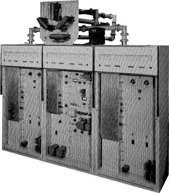
18 PHASING determine the pattern shape and size in both the vertical and horizontal planes, the maximum expected operating values of fields in both the nulls (minimum signal areas) and the lobes (maximum signal areas), the proper size, shape, height, spacing, and orientation of the antenna towers, and the phase relationships and amplitude ratios of the radiation fields of the individual antennas. This information is then submitted to the FCC with the application for a construction permit. A Collins 81M directional antenna phasing and branching system consists of : a branching circuit in which the power is divided in precisely the amounts of power necessary to give the proper ratio of fields from the individual antennas; an impedance matching circuit to match the power divider input impedance to the common point impedance at which the power input is measured; phase shifting networks in series with each of the transmission lines going to the individual antenna towers; the transmission lines themselves; and the impedance matching network between each of the transmission lines and its associated antenna tower. The power divider in Collins 81M equipment is usually 820 Series Cabinet. Available in I, 2 or 3 bays; depending upon Phasor requirements. 13
19 INPUT 1 I I a resonant tank circuit consisting of a large fixed coil tapped with smaller variable coils for power adjustment. An alternate design uses a group of variable coils, each one feeding a tower ; this group then becomes the tank coil of the circuit. For 1 kw or lower, the capacitive arm of the tank circuit is a capacitor and variable coil connected in series. The variable coil provides tuning adjustment by varying the over -all negative reactance in this branch of the tank. In higher powers, the tank capacitance is usually a variable vacuum capacitor in parallel with one or more fixed capacitors. INPUT I I POWER I PHASE I XMSN I ANTENNA I ANT. MATCHING (DIVIDER( SHIFTING I LINES I MATCHING NETWORKS( (NETWORKS' (NETWORKS T I I I I "w NET NET TYPICAL PHASING SYSTEM NET _L_ ±;: T.. NET T NET ( [. NET T.. NET NET v O v Phase shifting networks are "T" designed, with variable coils mechanically connected in tandem for the series arms and a coil and capacitor in series for a shunt arm. Wherever possible, 90 networks - capable of being adjusted ±300 from the design value - are supplied. Wherever a phase shift network is not required, a series variable coil and capacitor are used to supply variation of ±200 around a 0 setting. They are used for trimming phase shift of current in the towers in which they are used. "T" networks are also used for impedance matching at the tower base. The network has sufficient latitude of adjustment to match the transmission line impedance to any expected base operating impedance and still permit adjustment of phase shift. Switching of circuits for day and night operation or directional and non -directional operation is accomplished by impulse -type, toggle- operated RF relays, energized by pushbutton switches on the front panel. The pushbutton automatically removes the plate voltage of the transmitter before pattern switching and restores it when switching is completed. Interlocks on the cabinet doors also remove the plate voltage when doors are opened. Amplitude and phase controls have counters to assure accurate resetability. In complex arrays requiring additional controls, the controls and counters are behind the tilt -out panel in the lower half of the cabinet. Power dividing circuits and phase shift networks utilize heavy edge -wound copper ribbon inductors and ceramic cased mica capacitors. Vacuum capacitors are used where made necessary by high circulating currents. Plated 5/16" copper tubing is used for all RF busses and insulation is steatite or Mycalex. Input and output connections are provided at the top of the phasing cabinet unless otherwise specified. Special terminations are provided for solid dielectric cables in both the phasing cabinet and antenna coupling units. An input common point RF ammeter is supplied along with line current meter jacks. Antenna current meters have make -before -break switches, which can be operated without opening the cabinet door on the weatherproof coupling units. SPECIFICATIONS Power: 1, 5 and 10 kw in 2 -, 3 -, 4 -, 5 -, and 6 -tower arrays. Patterns : Directional day and night, same pattern; directional nighttime only; or different pattern day and night. Size: 20V -3 style cabinets measure 38" W, 76" H, 27" D (96.52 cm W, cm H, cm D) complex phasing systems may require two cabinets each identical to the above measurements. 820E /F style cabinets are available in 3 sizes to fit the complexity of the system. 25 7/16" W, 69" H, 32" D (64.59 cm W, cm H, cm D) 47 7/16" W, 69" H, 32" D ( cm W, cm H, cm D) 67 7/16" W, 69" H, 32" D ( cm W, cm H, cm D) COLLINS 564k -1 PHASE SAMPLING LOOP 14


. Weight: 50 lbs. (22.68 kg). Part No.")
20 3 PHASING Designed to sample the relative phase relationship of radio frequency energy from kc antenna towers in directional antenna arrays, the Collins 564A -1 is made of two loops of #10 copper wire which may be connected either in series or in parallel. The wires are contained within a loop of 7/8" painted, copper tubing which serves as an electrostatic shield. COLLINS 144A -1 ISOLATION COIL A universal coupling permits the loop to be connected to any type of pressurized or unpressurized air or solid dielectric transmission line. The loop offers a good match to lines of ohms impedance. A universal mounting bracket allows the loops to be mounted on any part of the antenna structure. Size: Approx. 30" W, 7' 6" H (76.2 cm W, cm H). Weight: 50 lbs. (22.68 kg). Part No Coil provides isolation for the sampling line in directional arrays, presenting a high impedance for the line across the base insulator. Unit consists of a phenolic coil form which will accommodate 37 turns (approx. 100 ft.) of RG8 /U or similar solid dielectric sampling line. May be mounted on wall of tuning shack or in housing similar to that pictured. Inductance: Approx. 180 microhenrys. Size: 10" diameter, 18" L (25.4 cm diameter, cm L). Weight: 6 lbs. (2.7 kg). Part No JOHNSON RF CONTACTORS The and contactors are especially designed for high voltage radio frequency switching and dc voltage switching in high voltage rectifier circuits. They require no "holding" power and will operate with a momentary application of voltage. Standard contactors are supplied with four auxiliary switches: two "normally closed" for control of solenoid voltage and two "normally open" for operation of signal lamps or other related functions. Solenoids are wired for 220 v, cps or 110 y, cps on special order. Part No (Type ) Part No (Type ) Part No (Type ) Part No (Type ) Maximum Type No. Current Contacts amps SPDT amps DPDT amps SPDT amps DPDT Maximum Contact Rating (at 2 mc) 17 kv, 25 amps (20.0 cm W, cm H, cm D) 17 kv, 25 amps (20.0 cm W, cm H, cm D) 22 kv, 25 amps (26.67 cm W, cm H, cm D) 22 kv, 25 amps (26.67 cm W, cm H, cm D) Size 15
21 F\i Transmitters
22 WHAT'S THE MYSTERY ABOUT STEREO? The mystery of stereophonic FM broadcasting is wiped away with the straightforward Collins approach. Not only does Collins equipment faithfully reproduce "live" sound in both direction and dimension, it also assures the stereo broadcaster a stable system of transmission. The Collins method of composite signal generation does away with the costly and unstable equipment needed in conventional double- injection system of stereo broadcasting. Amplitude differences result from the directional characteristics of the human ear and the baffle effect produced by the head. The time differences result from the difference in path length to each ear from a sound source which is off to one side. To provide a realistic stereo effect, the time delay and amplitude differences between the signal received by the left and right ears must be maintained from the original sound source to the ear of the listener. The problem becomes one of maintaining amplitude and phase differences to provide adequate channel separation. Left and right channels must have proper balance to give the listener faithful reproduction of a live presentation. If the source of sound moves to the left on the program stage, the left channel's volume must increase and the right channel's volume decrease proportionately to convey accurately the change of direction of the sound source. Adequate channel separation - at least 30 db - must be maintained. Lack of adequate separation would permit "bleeding" of one channel's sound into the other, thus moving the sound source to an apparent center from the listener's point of view. Finally, compatibility is required. The transmitted stereo signal must be capable of being received not only by the stereo FM receiver, but by existing monaural receivers as well. To comply with FCC requirements, a signal which can be received by monaural receivers must be transmitted. This signal is the combination of the left and right channels, or L + R. To achieve stereo broadcasting, a subcarrier FM signal provides the vehicle for the third dimensional sound. This is the L -R channel. The Collins 786M -1 FM Stereo Multiplex Generator achieves this L -R signal by a mathematical system of F111 TRANSMITTERS time division. More of this later. Basically, then, the stereo FM receiver gets two signals, an L + R and an L- R. To feed the left channel and the receiver's left speaker, the receiver adds the L + R and L -R signals and derives 2L. The same process by subtraction yields 2R in the right speaker. Since the figure 2 represents a volume control setting, the receiver in effect recovers the L and R sound originally produced at the left and right microphones on the program stage. Returning to the time division principle, it is this factor which makes the Collins Stereo Generator a standout unit in operation and maintenance. In the conventional stereo generation system, two channels are required to feed L + R and L -R to the exciter. This technique, known as matrixing, requires gain and phase shift between the two channels be maintained within close tolerances to maintain adequate channel separation throughout the system. Collins' new approach eliminates the need for continual surveillance of time delay shifting between the two channels by eliminating the double- injection system entirely. Instead, the direct FM wide band exciter is fed a single, composite signal on one wire. Any shift in gain or phase will affect both channels equally, thus maintaining the 35 db channel separation. Not only does this assure the broadcaster an inherently stable method of stereo transmission, but greatly simplifies both operation and maintenance. The rather expensive matrix networks needed in the dual channel system are eliminated as are the time delay switches needed to match the channels when a shift in gain or phase occurs. The Collins time division system of stereo signal generation is nothing more than a sampling at a 38 kc rate of left and right audio inputs. The output from the switch is equivalent to L + R plus the L -R double sideband components centered on the switching frequency (38 kc) and its odd harmonics. The composite wide band spectrum accepted by the exciter would include the L + R signal, a 10% 19 kc pilot carrier inserted for phasing reference, the L -R DSB components centered on the 38 kc subcarrier, and the 67 kc SCA channel when an auxiliary SCA generator is installed. DSB SIGNAL (L -R) FM SIGNAL (SCA) MAIN CHANNEL (L AND R) o KC KC KC i 38KC 53KC KC KC STEREO MULTIPLEX SPECTRUM IT
vu L AU010 ADD I0VD 38 KC 05C 75 SIM CARRIER BALANCE e CC-) 38 KC BUE 75 MIN c o STEREO -NON REMOTE CONTROL 38 KC DRIVER 75 MIN 19 KC.")

23 1. L: N1613 r' L1 L qq C: N16í3 :g A 0 C74 a _ 2N1175A L N1285 n o o MK OUTPUT 75 MIN R AUDIO ADD. )vu L AU010 ADD I0VD 38 KC 05C 75 SIM CARRIER BALANCE e CC-) 38 KC BUE 75 MIN c o STEREO -NON REMOTE CONTROL 38 KC DRIVER 75 MIN 19 KC.KD OSC 75 MIN NU75A MON UNE R REMOTE OVER RIDE STEREO ON K ON ï TP7OI TP7 G: 0 CA) OFF LEVEL METER CONTROL CARRIER CHAN SEP LR AMPL 786M -1 FM STEREO MULTIPLEX GENERATOR A stable and reliable method of stereophonic FM broadcasting is now available through the new time division system where both stereo channels are integrated into a composite signal which is fed to a wide band exciter (Collins A830-2) on a single line. The Collins 786M -1 FM Stereo Multiplex Generator does away with the inherent instability of the conventional dual channel method of stereo injection. Instead, the Collins 786M -1 feeds monaural audio and the subchannel, required for stereo operation, to the exciter on a single, composite signal. The time division system eliminates the costly and unstable dual channels which require matrix networks. L + R and L -R outputs of the matrix networks must be compensated to make up time differences in the two channels. Also, accurate amplitude balance between the two channels must be maintained. In the Collins system, this problem is eliminated by using a wide band direct FM exciter. With a system of this type, any gain changes or time delays will affect the main and sub -channels equally. The Collins time division system is nothing more than a sampling at a 38 kc rate of the left and right audio inputs. After transmission, a corresponding component in the FM receiver demodulates the composite signal in synchronism with the sampling, converting it to left and right audio through the respective speakers. The composite stereo signal (L + R and L - R) is achieved by filtering out unwanted harmonics created in the function of the four -diode time division switching circuit. The resulting spectrum shows only the main channel (L + R) which is the monaural signal; a 10% 19 kc pilot carrier; the subchannel (L - R) which is the stereo signal on a 38 kc carrier. An SCA channel may be placed on a 67 kc carrier by addition of an auxiliary SCA generator. Features of the 786M -1 are: SIMPLE CIRCUITS - The single line, time division system eliminates matrixing components, greatly simplifying circuitry. STABLE - All components are temperature- compensated to provide long -term stability. The unit is completely transistorized. SELF -METERED - An audio VU meter monitors both audio inputs and interior circuit points for rapid maintenance. EASILY INSTALLED - The Collins 786M -1 may be installed in the 830B -1A, 830D -1A or 830E -1A FM, 830ElA. 830F -2A, A, 830N -1A. 18
24 FM TRANSMITTERS L AUDIO PRE -EMPHASIS NETWORK HI -PASS FIL XFMR I5KC LP FI LIER EMITTER FOLLOWER R AUDIO PRE- EMPHASIS NETWORK HI- RASS FIL a EMITTER n I5KC LP XMFR FILTER FOLLOWER 38 KC OSCILLATOR 38KC BUFFER 38KC DRIVER SWITCH 53KC LOW -PASS LINEAR PH FIL TP 701 V OUTPUT 50CPS TO 53KC o-z PILOT OFF -ON - PILOT PHASE PILOT AM EMITTER FOLLOWER 19 KC LOCKED OSCILLATOR A TP702 BLOCK DIAGRAM 786M -I Pre -emphasis networks are plug -in type; can be replaced with 20 db flat pad for testing. Hi -pass filter and 600 ohm -600 ohm transformers prevent interference with exciter AFC circuits by any 5 cps components in input. Transformers convert from balanced to unbalanced inputs. 15 kc low pass filters limit bandwidth to 15 kc to prevent cross -talk between main and sub -channels. Filters provide over 60 db attenuation for frequencies above 19 kc. Emitter followers provide isolation between left and right audio inputs and stereo switch. 38 kc oscillator, buffer and driver provide 38 kc drive signal to the stereo switch. When 38 kc carrier goes positive, upper pair of diodes in switch conduct and connect left channel to output; when carrier goes negative, lower pair of diodes connect right channel to output. L + R correction is obtained by feeding left and right signals around switch through two resistors. The 53 kc low pass linear phase filter removes high frequency switching components which would fall outside the assigned bandwidth. The filter meets the requirement of constant time delay for all frequencies up to 53 kc. Main channel audio and sub - channel DSB crossings thus occur simultaneously. The filter also has flat frequency response to 53 kc. These two factors are held to tolerances which provide over 35 db channel separation for 50-15,000 cps audio input frequencies rising to 38 db at 5 kc. The emitter follower and 19 kc locked oscillator provide a 19 kc pilot carrier in phase with the 38 kc subcarrier at the output of the linear phase filter. Distortion (either channel) : Less than 1 %, 50-15,000 cps. Channel Separation: 35 db or greater, rising to 38 db at approx. 5 kc. Pilot Carrier Stability: ±2 cps at 19,000 cps. Output Impedance: 600 ohms unbalanced. Size: 19" W, 834" H, 31/8" D. Weight: 14 lbs. Part No


25 MONO OR STEREO INPUT f MOD DISCR DC CONTROL I4MC AUDIO FEEDBACK BAL MIXER PA IO WATTS - MIN OF RF OUTPUT GATE FILTER 74-94MC OSC 5CPS KEY GATE DISCR AMPL SYNC DET I4MC REF BLOCK DIAGRAM A830-2 COLLINS A WATT DIRECT FM EXCITER An ideal, independent unit that may be used in educational stations or for other similar low power applica- tions, the Collins A830-2 is a 10 -watt direct FM exciter that accepts audio inputs from a monophonic, stereo (see Collins FM Stereo Multiplex Generator description, or SCA source by telephone lines or direct connection and modulates an existing carrier to provide an RF drive signal for direct transmission or further amplification. The unit serves as the exciter portion of the Collins 830BlA and 830E -1A FM Transmitters (see descriptions) and may be rack mounted in 10 -watt installations. Power Source: 117 v ac ±5 %, cps, single phase. Power Supply Voltages: +20 v dc ±0.1 v, regulation ±0.1 v; ripple 0.5 %. -10 v dc ±0.1 v, regulation ±0.1 v; ripple 0.5 % v dc ±5.0 v, regulation ±10 v; ripple 1%. Carrier Frequency Stability: Not more than ±1000 cps. FM Noise Level: 65 db below 100% modulation ( ±75 kc). AM Noise Level (RMS) : 55 db below 100% AM level. Tube Complement (one each): 6U8 6AU6 12AT E26 Size: 19" W, 261/4" H, 33/8" D (48.26 cm W, cm H, 8.57 cm D). Weight: 42 lbs. (19.05 kg). Part No Consists of 10 -watt exciter, set of tubes, transistors, power rectifiers, crystal and instruction book. Rack mounted unit. No Part Number Complete set of spare tubes, plug -in transistors plus power rectifiers for 830A -2. No Part Number FCC set of spare tubes, plug -in transistors plus power rectifiers for 830A -2. No Part Number Spare crystal operating frequency for A waft exciter. Part No Spare 14 me crystal. 20

26 FM TRANSMITTERS COLLINS 830B-1A FM TRANSMITTER Designed for top reliability and superior quality sound, the Collins 830B -1A 250 Watt FM Transmitter not only affords the broadcaster an economical, self- contained unit, but also is readily adaptable to a variety of uses, including stereophonic FM and increased station power. Clean, sharp lines plus "humanized" engineering for both operation and maintenance make the Collins 830BlA an attractive, integrated unit in the most modern broadcast station. Other quality features of the Collins 830B -1A which underscore its superior performance include: SELF -CONTAINED - Transformers for the all solid state power supply as well as the harmonic filter are housed inside the cabinet. Self- contained multiplexing equipment, including the Collins 786M -1 Stereo Generator, also may be installed inside. Space is provided for power transformers when the unit is used as a driver for the 830E - la 5,000 Watt Transmitter. SIMPLE OPERATION - The 830B -1A is pushbutton operated, featuring a "step- start" system in which starting sequences are fully automatic. All RF circuits are tuned from the front panel. Adequate metering is provided for rapid operation analysis. All adjustments can be made while the transmitter is on the air. DEPENDABLE - The compact transmitter uses space - saving silicon rectifiers which generate a minimum of 21


27 A heat. Spurious radiation is minimized and the unit has a high degree of stability. MAINTENANCE EASE - Vertical panel construction eliminates hidden components and allows rapid inspection and maintenance. Cabinet interlocks minimize danger during circuitry inspection and maintenance. A grounded shorting stick is readily accessible to discharge capacitors before transmitter servicing. RIGID TESTING - In accordance with rigid Collins standards, the 830B -1A is tested on the broadcaster's channel under proper load conditions prior to shipment. The 830B -1A can meet a variety of power situations. Only the blower motor need be changed to convert from the nominal 60 cycle to 50 cycle operation. Frequency Range: mc. Power Output: 250 watts. Carrier Frequency Stability: ±1000 cps. Audio Frequency Response: ±1 db, 50-15,000 cps. Distortion: Less than 1%, 50-15,000 cps. FM Noise Level: 65 db below ±75 kc. AM Noise Level: -55 db rms. Harmonic Attenuation: At least -67 db. Modulation Capability: ±100 kc. RF Output Impedance: 50 ohms; SWR not to exceed 2:1. Audio Input Level: +10 dbm, ±2 db. Power Source: 230 v ac nominal, 60 cps, 1 phase (tapped for v in 10 v steps). Input Power Requirement: 860 watts, 90% power factor. Power Line Regulation: 3 %. Variations: Slow line, ±5 %; rapid line, ±3 %. Tube Complement: 2 OD U8 1 2E AT7 1 4CX250B 1 6AÚ6 Temperature Range: C. Humidity: 0% - 95 %. Altitude: 6000 ft. ( m). Size: 38" W, 76" H, 27" D (96.52 cm W, cm H, cm D). Weight: 638 lbs. (2894 kg). Part No W 830B- I 22 FM TRANSMITTER


28 FM TRANSMITTERS COLLINS 830D-1A FM TRANSMITTER Carefully- engineered design, straight- forward circuitry, clean -line cabinetry all make the Collins 830D -1A FM Transmitter a powerful and versatile installation in the most modern station. The self- contained 1,000 watt unit achieves a new degree of reliability and operational ease never before obtainable by the FM broadcaster. The new approach A Watt Exciter is the heart of the 830D -1A. This wide band direct FM unit accepts a composite stereo signal directly without using auxiliary modulators for either the stereo or SCA channels. Operation and maintenance of the Collins 830D -1A is simplicity itself. Fewer components and fewer tuned circuits enhance the dependability and operational ease of the transmitter. Some of its features are: SELF- CONTAINED - Transformers for the all solid state power supply as well as the harmonic filter are enclosed in the cabinet. Self- contained multiplexing equipment, including the Collins 786M -1 Stereo Generator, also may be mounted inside. SIMPLE OPERATION - The 830D -1A is pushbutton operated, featuring a "step- start" system in which starting sequences are fully automatic. All RF circuits are tuned from the front panel. Adequate metering is provided for rapid operational analysis. All adjustments can be made while the transmitter is on the air. DEPENDABLE - Space- saving silicon rectifiers which generate a minimum of heat are employed. A regulated 23


29 filament transformer prolongs tube life. Stability is enhanced through the neutralized final power amplifier. Spurious radiation is held to a minimum; thè entire unit has a high degree of stability. MAINTENANCE EASE - Vertical panel construction eliminates hidden components and allows rapid inspection and maintenance. Cabinet interlocks minimize danger during circuitry inspection and maintenance. A grounded shorting stick is readily accessible to discharge capacitors before transmitter servicing. RIGID TESTING - In accordance with rigid Collins standards, the 830D -1A is tested on the broadcaster's channel under proper load conditions before shipment is made. The 830D -IA can meet a variety of power situations. Not a single component need be changed to convert from nominal 60 cycle operation to 50 cycle. Frequency Range: mc. Power Output: 1000 watts. Carrier Frequency Stability: ±1000 cps. Audio Frequency Response: ±1 db, 50-15,000 cps. Distortion: Less than 1 %, 50-15,000 cps. FM Noise Level: 65 db below ±75 kc. AM Noise Level: -55 db rms. Harmonic Attenuation: -73 db. Modulation Capability: ±100 kc. RF Output Impedance: 50 ohms; SWR not to exceed 2:1. Audio Input Level: + 10 dbm, ±2 db. Power Source: 230 v ac nominal, cps, 1 phase (tapped for AT in 10 v steps). Input Power Requirement: 2300 watts, 90% power factor. Power Line Regulation: 3%. Variations: Slow line, ±5%, rapid Tube Complement: 1 6U AT AU6 1 Temperature Range: C. Humidity: 0% - 95%. Altitude: 6000 ft. ( m). Size: 38" W, 76" H, 27" D ( cm D). Weight: 776 lbs. ( kg). Part No line, ±3% E26 4CX1000A cm W, cm H, 830D -IA FM TRANSMITTER 21

30 Fh1 TRANSMITTERS COLLINS 830E-1A 5,000 WATT FM TRANSMITTER Award -winning design and "humanized" engineering, hallmarks of Collins quality, are reflected in the Collins 830E -1A 5,000 Watt FM Transmitter. One cabinet houses the A830-2 Direct FM Exciter and the 250 watt B830-1 Driver Unit; the other houses the 5,000 watt, single stage transmitter. Features of the Collins 830E -1A are: SELF- CONTAINED - Every component is housed inside the two cabinets, including power transformers, harmonic filter and directional coupler. An optional accessory is the Collins 786M -1 Stereo Generator which fits inside the driver unit cabinet. Installation of the 786M -1 is a matter of minutes. SIMPLE OPERATION - The transmitter is pushbutton operated, featuring a "step- start" system in which starting sequences are fully automatic. Highly stable RF circuits are tuned and metered from the front panel, and all adjustments can be made while the transmitter is on the air. No tuning or trimming of the harmonic filter is required. The PA stage is easily neutralized and is not critical in adjustment. DEPENDABLE -Grounded screen, eliminating the screen bypass capacitor, does away with a common source of failure. Driver power supply uses silicon rectifiers which take little space and generate a minimum of heat. Efficient blowers force air directly on the 4CX250B and 4CX5000A power amplifier tubes. Power supply is all solid state with the exception of the final amplifier plate voltage supply which uses mercury vapor rectifiers. MAINTENANCE EASE - Vertical panel construction eliminates hidden components and allows rapid inspection and maintenance. Cabinet interlocks minimize danger during 25


. Input Power Requirement: 11 kw, 90% power factor. Power Line Regulation: 3%. Variations: Slow line, ±5%; rapid line, ±3%.")
31 circuitry inspection and maintenance. A grounded shorting stick is readily accessible to discharge capacitors before transmitter servicing. RIGID TESTING - In keeping with rigid Collins standards, the 830E -1A is tested on the broadcaster's channel under proper load conditions be /ore the unit is shipped. While the transmitter nominally operates on 60 cycle power, only the two blower motors need be changed to convert to 50 cycle operation. Frequency Range: mc. Power Output: 5000 watts. Carrier Frequency Stability: ±1000 cps. Audio Frequency Response: ±1 db, 50-15,000 cps. Distortion: Less than 1 %, 50-15,000 cps. FM Noise Level: 65 db below ±75 kc. AM Noise Level: -55 db rms. Harmonic Attenuation: -80 db. Modulation Capability: ±100 kc. RF Output Impedance: 50 ohms; SWR not to exceed 2:1. Audio Input Level: + 10 dbm, ±2 db. Power Source: 230 v ac, 60 cps, 3 phase (tapped for IT in 10 v steps). Input Power Requirement: 11 kw, 90% power factor. Power Line Regulation: 3%. Variations: Slow line, ±5%; rapid line, ±3%. Tube Complement: 2 OD3 1 2E26 1 6U8 1 4CX250B 1 12AT A* 1 6AU6 1 4CX5000A Temperature Range: C. Humidity: 0% - 95 %. Altitude: 6000 ft. ( m). Size: 76" W, 76" H, 27" D ( cm W, cm H, cm D). Weight: 1800 lbs. ( kg). *Not used if silicon diode rectifiers are employed. Part No POWER AMPLIFIER REAR VIEW 26 DRIVER REAR VIEW


32 FM TRANSMITTERS POWER AMPLIFIER REAR VIEW COLLINS 830E-1A/10 KW FM TRANSMITTER The Collins 830F -1A 10 KW FM Transmitter assures the broadcaster the clean, strong signal he needs to make his programming outstanding in a highly competitive market area and the extended coverage required to build and maintain an audience. Like all Collins FM transmitters, the two -cabinet 10,000 watt model is carefully engineered and manufactured to a quality level that is a hallmark at Collins. SELF- CONTAINED - Every component is housed within the two cabinets, including power transformers, harmonic filters and directional coupler. An optional feature is the Collins 786M -1 Stereo Generator which mounts in minutes in the 250 watt driver cabinet. EASE OF OPERATION - Pushbutton operated, the transmitter starting sequences are fully automatic by the "step- start" system. RF circuits are tuned and metered at the front panel. All adjustments can be made while the transmitter is on the air. No tuning or trimming of the harmonic filter is required. The PA stage is easily neutralized and is noncritical in adjustment. DEPENDABLE - Grounded screen eliminates the bypass capacitors, doing away with a common source of failure. The driver power supply uses solid state silicon rectifiers which generate little heat and require a minimum of space. The final amplifier plate voltage supply uses mercury vapor tubes or optional silicon diode rectifiers. Efficient blowers force cooling air directly on the power tubes. MAINTENANCE EASE - All components are easily accessible and may be rapidly inspected through the use of 27


33 POWER AMPLIFIER FRONT VIEW vertical panels. All panels are interlocked for safety; a grounded shorting stick is provided. RIGID TESTING - In keeping with rigid Collins standards, the transmitter is tested under actual load conditions on the broadcaster's channel before the unit is shipped. While the transmitter is designed for 60 cycle operation, only the blower motors and plate contactors need be changed for 50 cycle use. Collins also manufactures the 830F -2A transmitter. This unit uses an 830D -1A 1,000 watt driver, required when the additional PA is installed for 20,000 watt operation. If an eventual increase to 20KW is planned, the 830F -2A should be installed initially. Frequency Range: mc. Power Output: 3,000-10,000 watts nominal. Carrier Frequency Stability: ±1,000 cps. Audio Frequency Response: ±1 db, 50-15,000 cps. Distortion: Less than 1 %, 50-15,000 cps. FM Noise Level: 65 db below x-75 kc. AM Noise Level: -55 db rms. Harmonic Attenuation: -80 db. Modulation Capability: ±-100 kc. RF Output Impedance: 50 ohms; SWR not to exceed 2:1. Audio Input Level: +10 dbm, ±2 db. Power Source: 230 v ac, cps (50 cps optional), 3 phase (tapped for v in 10 v steps). Input Power Requirement: 20 kw, 90% power factor. Power Line Regulation: 3%. Variations: Slow line, ±5%; rapid line, ±3 %. Tube Complement: 2 OD3 1 6AÚ6 1 4CX250B 1 6U A* 1 12AT7 1 2E26 1 4CX5000A Temperature Range: C with mercury vapor rectifiers C with silicon diode rectifiers. Humidity: 0% -95%. Altitude: 6,000 ft. ( m). Size: 76" W, 76" H, 27" D (193 cm W, 193 cm H, 68.6 cm D). Weight: 1,900 lbs. (861.8 kg). "Not used if silicon rectifiers are employed. Part No Part No (Type 830F -1A) (Type 830F -2A) 28


34 FM TRANSMITTERS COLLINS 830H -1A /20 KW FM TRANSMITTER For the broadcaster requiring extended coverage in major markets, Collins offers the 830H -1A, a 20,000 watt FM transmitter contained in only three cabinets. Use of a diplexing system assures continuous duty even though one of the two power amplifiers is removed from service for routine maintenance or repair. Careful engineering, use of conservatively -rated components and precision manufacturing techniques assure the broadcaster of quality upon which he can depend. Outstanding benefits of the 830H -1A are: SELF -CONTAINED - Every component, including power transformers, harmonic filters and directional couplers, are housed within the three cabinets. Only the diplexer assembly is mounted on the exterior. While the photograph shows a top mounted diplexer, this assembly may be located anywhere convenient to the broadcaster. An optional accessory is the 786M -1 Stereo Generator, which mounts in minutes inside the driver cabinet. SIMPLE OPERATION -A pushbutton -operated "step - start" system assures automatic starting sequencing. RF circuits, tuned and metered at the front panel, may be adjusted while the transmitter is on the air. The harmonic filter requires no tuning or trimming. The PA stage is neutralized easily and is noncritical in adjustment. DEPENDABLE - In event of a PA outage, the transmitter remains on the air at 6 db lower output until the an- 29


35 tenna is patched to one amplifier to permit half -power ( -3 db) operation while the disabled PA is being restored to service. The transmitter is not off the air during this operation. A grounded screen eliminates the bypass capacitors, common trouble points. Independent driver power supply is solid state, requiring little space and generating little heat. The PA power supply consists of mercury vapor tubes, with a solid state supply an optional feature. Efficient, quiet blowers force air directly on the 4CX1000A and two 4CX5000A power amplifier tubes. MAINTENANCE EASE - All components are easily accessible for inspection and maintenance through vertical panel construction. All cabinet panels are interlocked for safety; a grounded shorting stick is installed in each cabinet to discharge capacitors before servicing. RIGID TESTING - The 830H -1A, like all Collins transmitters, is tested on the broadcaster's channel under actual load conditions before shipment. While the transmitter nominally operates on 60 cycles. only the blower motors and plate contactors need be changed for 50 cycle operation. Frequency Range: mc. Power Output: 6,000-20,000 watts nominal. Carrier Frequency Stability: ± 1,000 cps. Audio Frequency Response: ±1 db, 50-15,000 cps. Distortion: Less than 1%, 50-15,000 cps. FM Noise Level: 65 db below ± 75 kc. AM Noise Level: -55 db rms. Harmonic Attenuation: -80 db. Modulation Capability: ±100 kc. RF Output Impedance: 50 ohms; SWR not to exceed 2:1. Audio Input Level: + 10 dbm, ±2 db. Power Source: 230 v ac, 60 cps (50 cps optional), 3 phase (tapped for v in 10 v steps). Input Power Requirement: 40 kw, 90% power factor. Power Line Regulation: 3 %. Variations: Slow line, ±5%; rapid line, ±3 %. Tube Complement: 1 6U8 1 2E AT7 1 4CX1000A 1 6AU A* CX5000A Temperature Range: C with mercury vapor rectifiers; C with silicon diode rectifiers. Ilunzidity: 0% - 95 %. Altitude: 6,000 ft. ( m). Size: 114" W. 76" H, 27" D (289.6 cm W, 193 cm H cm D). Weight: 2,900 lbs. (1315 kg). *Not used if silicon diode rectifiers are employed. Port No N-1A FM TRANSMITTER For the broadcaster whose market includes extensive mobile reception, Collins sells the 830N -1A, a dual 10,000 watt transmitter. This unit transmits 10,000 watts through vertically polarized antennas for automobile receivers and 10,000 watts to the horizontally -polarized antennas for home receivers. Part No H -IA FM TRANSMITTER


36 Antennas, Towers, Transmission Lines \


37 COLLINS 37M FM ANTENNA A proven design that has been imitated but never duplicated in efficiency during the past decade, the Collins 37M Antenna still maintains its position of leadership in FM broadcasting. The advanced design features of the unit make it an ideal antenna for stereo and multiplex operations. The aerodynamic simplicity and low weight of the 37M provide greater efficiencies and savings in new tower costs, erection time and maintenance expense. These features also eliminate undue oscillating and weaving of the tower and antenna. The Collins 37M Ring Antenna consists of only two basic parts: the radiating ring and the connecting interring transmission line. Any number of rings, either odd or even, may be used to provide maximum flexibility in high power gain. Antenna arrays mounted on 15/8" or 31/8" line are available for handling transmitter powers up to 20 kw. Antenna assemblies on 15/8" line are rated for power inputs at base of antenna up to 2.5 kw for a single ring array; 10 kw for four or more rings. Antenna assemblies on 31/8" line are rated for power inputs up to 2.5 kw per ring at base of antenna with maximum of 20 kw for eight or more rings. Only one inter -element transmission line is required to feed all rings in a multiple element array. The individual radiating rings are identical mechanically and electrically. They are both shunt fed and supported by a single interconnecting feed line, which consists of modified lengths of standard EIA rigid coaxial line insulated with Teflon. The Collins 37M FM Antenna feed system has a stub at the top of the array which is capacitive and ade- quately removes the inductive reactance created by the shunt feed on the ring. The 37M terminates in a standard EIA 50 ohm flange connection on the bottom element of the array for coupling directly to 15/8" or 31/8" transmission line. The horizontal radiation pattern of the Collins 37M FM Antenna is essentially circular for both top mounting and side mounting arrays. The extent of deviation from a circular pattern in the side mounted antenna is dependent on the type and size of tower on which the antenna is mounted. In cases of very large supporting structures and in all cases where guy wires are used, expert recommendations should be requested on spacing of insulators and guy wires and mounting of the antenna. Insulators should be placed where the guys attach to the tower and guys should also be broken with insulators approximately every three feet for 15 feet in the immediate area of the antennas. The voltage standing wave ratio of the Collins 37M Antenna can be maintained at better than 1:15:1 when field tuned due to the inherently high stability of the tuning system. The capacitor plates of the 37M are adjustable for optimum performance and equal power distribution through all rings. These features allow an accurate prediction of the gain from the given number of loops in the array. Adequate bandwidth virtually eliminates detuning effects caused by changes in atmospheric conditions. The bandwidth and linearity of the antenna are more than adequate for multiplexing service. The compactness and simpility of the 37M allow maximum efficiency in ice removal. Each ring may be equipped with an internally mounted, 200 -watt heating unit which consists of a cartridge type element inside each of the tuning capacitor plates and an additional flexible heating element extending the full circumference of the inside of the ring. The simplicity of the heating arrangement makes it possible to replace the elements in the field if necessary. The absence of large masses of metal assures efficient and practical deicing of the antenna and capacitor, which is the most critical part of the antenna when icing occurs. The 37M Antenna is easy and quick to erect. There are no heavy hoisting problems so that many hours of erection time can be saved. Support brackets are specially fabricated for each installation to match the tower and mounting arrangement, thus minimizing erection problems at the site. Either guyed or self- supporting towers will in nearly all cases support the side mounting 37M. Towers which support top mounting television antenna arrays increase their usefulness with the addition of a side mounting 37M Antenna. Top or pole mounting design is available on special order for installation on towers where no TV antenna is present or planned. This type of mounting provides the maximum in height and coverage. The light weight and windloading of the top mounting series allows erection on 32


38 most guyed and self-supporting towers without extensive tower modification. Further information and quotations on the 37M FM Directional Antenna will be supplied upon request. Part No Type and Number of Rings 37M -I 37M -2 37M -3 37M -4 37M -5 Part No Type and Number of Rings 37M -6 37M -7 37M -8 37M M -12 For top mounted, with mast rings mounted on 15/8" Line or We" Line, Part Number remains the same for the specified number of rings. No Part Number 37M FM Antennas for power inputs over 20 kw. Part No Deicer per bay installed at the factory. Part No Replacement heating element. Two required per ring - 60v. Part No Replacement heating element. Two required per ring - 115v. wo CS*WS MOOED GuipE.,MGE MO $OCYEi i09 POLE ON TOWER Ev ANTENNAS COLLINS 37 -M ANTENNA SIDE MOUNTED I Collins No. of Power A ** On 15/8" Line On 31/8" Line Type Rings Gain Field Gain db Gain Feet & Inches B * ** Weight(Ibs.) B * ** Weight(lbs.) 37M -I I ' 5" M M M M M M M M -9* M -I0* M -I2* M -14* M -16* * Antennas of over 8 bays are center fed with even numbers of bays or at 1/2 bay separation below center with odd numbers of bays. ** Computed for 100 Mc. For other frequencies multiply by 100 divided by frequency in Mc /s. * ** Wind loads based on 60 pounds on flat surfaces, 40 pounds per square foot on projected areas of cylindrical surfaces with all sections considered round. COLLINS 37 -M ANTENNA TOP MOUNTED No. On 15/a" Line On 31/e" Line Collins of Pwr. A B C D E F G H Dead D E F G H Dead Type Rgs. Gn. Ft. Ft. Ft. Ft. Dia. Dia. Lbs. Ft. -Lbs. Wt. Ft. Dia. Dia. Lbs. Ft. -Lbs. Wt. 37M -1 I '/ " 3' /e" ' /s" 3' /e" M ± '/2" 4'/3" 239 2, '/ " 4'h" 291 3, M ± s/e" 6V8" 403 5, /e" 6Vs" 486 6, M ± %" 7 %" , %" 7 %" , M ± %" 75/8 " , %" 9 %" , M ± %" 8 %" , '/4" 9 %" 1 31, M ± /4" 8%" , /4" 8%" , M -8* ± /4 " 9 s/b " , /4 " 1 1 3/4 " 1 58, *up to 12 bays on application ANDREW FITTINGS FOR COLLINS 37M -FM ANTENNA The following end terminals and fittings are required for connection of various types of transmission line to Collins 37M FM Antenna. The 37M is supplied with 15/8" or 31/8" line. The following lists only Andrew fittings for antenna end of transmission line to antenna line. Be sure to specify correct fitting for transmitter end. ANDREW H5-50, 7/8" Heliax to 15/8" 37M: 75AR EIA Flange and 1860 Reducer (inner connectors supplied with 75AR and 1860). ANDREW H7-50A, 15/8" Heliax to 15/8" 37M: 87R EIA Flange (with inner connector). ANDREW H7-50A, 15/8" Heliax to 31/8" 37M: 87R EIA Flange (with inner connector) and 1861 Reducer. ANDREW H8-50A, 3" Heliax to 31/8" 37M: 78R EIA. AMPHENOL RG 17U, 7/8" Solid to 15/8" 37M: Plug, Inner Connector and 2361 Adapter. ANDREW 560, 7/8" Rigid to 15/8" 37M: 1860 Reducer (with inner connector). ANDREW 561, 15/8" Rigid to 15/8" 37M: Inner Connector. ANDREW 562A, 31/8" Rigid to 15/8" 37M: 1861 Reducer (with inner connector). ANDREW 562A, 31/8" Rigid to 31/8" 37M: Inner Connector. 33

39 COLLINS 300C VERTICALLY POLARIZED FM ANTENNA Collins 300C vertically polarized FM antenna can significantly improve your FM coverage. Here's how: FCC regulations permit simultaneous FM radiation in both horizontal and vertical planes. For example, if your station is authorized for 5 kw ERP (horizontal), vertical radiation can be added up to the same power. Stations now operating with greater ERP than specified in new FCC rules for their classification may radiate vertically up to the maximum ERP specified in the rules. Two methods are commonly used: (1) A single power amplifier and transmission line to provide power for each antenna. (2) Two power amplifiers fed from a common exciter - driver and two transmission lines. The antennas are fed separately. The preferred method will be dictated by your power situation. If minimum initial investment is your primary concern, the first method is preferred. If redundance is important, the second method permits either amplifier to be operated individually or both simultaneously. The recommended ratio of vertical to horizontal ERP is unity. Collins Type 300C costs no more than your present horizontal bays, can be installed on your present tower and is compatible with your FM transmitter. Vertical polarization with Collins 300C: fills in shadow areas reduces null effects improves fringe area reception vastly improves car FM radio reception maintains FM stereo quality improves SCA operation TYPE 300C ANTENNA SIDE MOUNTED Power Rating Length Type No. of Dipoles Power Gain Field Gain DB Gain On 15/e" Line On 31/a" Line Feet & Inches 300 -I I II * * * I I II * III * I * Type Weight On 15/6" Line On 31/8" Line Wind Load ** On 11/4" Line On 31/3" Line Over Turning Moment * ** On 15 /e" Line On 31/8" Line o o III ,190 1, ,900 4, ,350 10, ,300 17, ,100 27, ,900 38, * ,200 51, * ,100 67, * ,400 84, * , , * , , * , , * Antennas of eight bays and over are center fed with even numbers of bays or at a point 1/2 bay below center with odd numbers of bays. ** Wind load in the direction through the mounting toward the tower computed for 60 lbs. on flat surfaces and 40 lbs. on projected areas of cylindrical surfaces. For 60 lbs. wind loading direction through the mounting toward the tower and referred to the center line of the bottom bay. * * *
40 TOWERS AM AND FM TOWERS Collins furnishes a wide selection of both self- supporting and guyed antenna towers to meet the requirements of any AM or FM installation. Towers are normally supplied with a protective coating of rust inhibitive paint prior to shipment, although they can be supplied with a galvanized finish at a slightly higher price. Galvanized is recommended in locations where the tower will be subjected to salt water spray, extreme humidity or other corrosive conditions. The finish coat is normally supplied by the tower erector and is in keeping with FAA requirement. All hardware, fittings, guy insulators, anchor steel and base insulator (where required) are supplied with each tower. The applicable FCC (FAA) lighting kit and wiring are also provided. UTILITY TOWERS Available in the six basic designs shown, Utility towers meet or exceed EIA specifications. In the five standard models, steel pipe members are welded together in 20- foot sections, except for the top section length which is according to individual specification. The Type 170 KD tower is of bolted angle -iron construction in 10 -foot sections. Anchors are individually designed to meet the requirements of each tower installation. The I -beam used is imbedded in a concrete slab re- inforced with steel rods and with an earth fill on top. Each section receives one coat of rust inhibitive, primer paint. Guy lines are galvanized and have a minimum breaking strength of at least twice the maximum calculated loads. No Part Number Tower Type Maximum Recommended Height Tower Width Weight Per Foot* Type of Base Insulation ft. (146.3 m) 33 in. ( cm) 28 lbs. (12.7 kg) Locke or Lappe ft. ( m) 197/8 in. ( cm) 17 lbs. (7.71 kg) Utility ft. (76.2 m) 19,',; in. (49.37 cm) 121/2 lbs. ( 5.67 kg) Utility ft. (60.96 m) 1671; in. (41.12 cm) 10 lbs. (4.54 kg) Utility ft. (60.96 m) 13V4 in. ( cm) 8 lbs. (3.63 kg) Utility KD 320 ft. (97.54 m) 18 in. (45.72 cm) 17 lbs. (7.71 kg) Utility 3401 *Tower steel only. Weight of guys, insulators, etc., not included. 35
41 FOOTAGE TABLE FOR BROADCAST TOWER HEIGHTS KC METERS KC TO WAVE KC '/2 WAVE /4 WAVE KC METERS I KC TO WAVE KC '/2 WAVE /4 WAVE


42 TOWERS WIND VELOCITIES AND CORRESPONDING PRESSURES TRUE "EXTREME' VELOCITY MILES PER HOUR Va CYLINDRICAL SURFACES Pressure in Lbs. /Sq. Ft. of Projected Area P = 0.002SV2 FLAT SURFACES Pressure in Lbs. /Sq. Ft. of Projected Area P = Va I HUGHEY & PHILLIPS RING TRANSFORMER For use wherever 60 cps energy must be transferred across two points with very low capacitance or at very high voltages. Provides a highly reliable, low capacity means of supplying power across base insulator or insulated radio towers employed as radiators. Their relatively large spacing and low capacity between windings make these isolation transformers desirable for use in directional arrays, and especially with radiators which develop very high voltages across the base insulators. No tuning or RF adjustments are necessary. Available in load capacities of 1750 watts (Model TI 2017) and 3500 watts (Model TI 2035) 115/230 volts. Part No (Type TI 2017) Part No (Type TI 2035) FISHER -PIERCE DB BEACON LIGHT CONTROL COPPER GROUND WIRE Bare #10 copper ground wire is used for dials. Wire attaches to mesh ground screen. Weight: 31.8' per lb. Part No ground ra- COPPER GROUND STRAP This fine quality copper ground strap is available in two sizes: 2" x.032" (4.02' per lb.), and 4" x.032" (2.01' per lb.). Par? No Part No (2" strap) (4" strap) TRUSCON MESH GROUND SCREEN Expanded copper mesh ground screen is for use beneath base of antenna tower to increase soil conductivity. Available in 8' x 24' sheets. Part No Designed to mount in a standard commercial meter socket. The 63305DB will automatically control broadcast tower lights directly or with auxiliary contactors. Adjustable potentiameter allows adjustment for operation from 0 to 50 f.c. Power Requirements: volts, 50/60 cycles. Built -in Load Contactor: Single Pole, Single Throw, Double Break. Load Rating: 3,000 watts. Part No
43 SOLID DIELECTRIC CABLES UHF CABLE PLUG ANDREW (Male), Type PL -259A. Part No TYPE RG -8 /U TYPE RG -17 /U UHF RIGHT ANGLE CONNECTOR ANDREW (Male -Female), M Andrew , Type RG -8 /U - Used for jumper connections between equipment and to HELIAX. Use types N and UHF connectors below. Part No Andrew , Type RG -17 /U - Used for longer jumper connections. Use type LC connectors below. Part No CABLE FITTINGS ADAPTOR UHF Jack ANDREW (Female)- N plug (Male) UG-146A/U. UHF JUNCTION ANDREW (Female both ends), PL Use between two Types N CABLE PLUG ANDREW (Male) Type UG- 21D /U. (NPN) Part No UHF TEE CONNECTOR ANDREW (Female -Male -Female), M -358 N JUNCTION ANDREW (Female both ends). Use between two Types Type UG- 29B /U. (NPN). ADAPTOR UHF Plug ANDREW (Male) - N Jack (Female) UG -83B / U. N RIGHT ANGLE CONNECTOR ANDREW (Male -Female), Type UG- 27B /U. (NPN). LC JUNCTION ANDREW (Female both ends), UG- 215/U. Use between two Types N CABLE JACK ANDREW (Female) Type UG -23/U. (NPN). LC CABLE PLUG ANDREW (Male), UG- 154A /U. N JUNCTION ANDREW (Male both ends), UG- 57B/U. Use between two Types N CABLE PLUG ANDREW (Male), for use with RG -17 /U, UG- 167E /U. N PANEL RECEPTACLE ANDREW (Female), UG- 58A /U. UHF CABLE PLUG ANDREW (Male), for use with RG-17/U. 38


44 TRANSMISSION LINES AIR DIELECTRIC HELIAX ACCESSORIES TYPE N JACK (Female) mates with UG /4" Cable -TYPE 71N. 3 /s" Cable -TYPE 72N. 1/2" Cable -TYPE 74N. These small diameter air dielectric Heliax cables are ideal for use as sampling lines and in phased arrays where stability of electrical characteristics is important. For all uses, the copper inner and outer conductors assure optimum performance. Types H1 and H2 are phase stable cables having coefficients of phase velocity change with temperature on the order of one part per million per degree Fahrenheit. Teflon insulated cables, with 35% higher power ratings are available in the 1/," size; Types HT4-50 (unjacketed) and HTJ4-50 (polyethylene jacketed). Type 74 series connectors are suitable for use with these cables. TYPE N PLUG (Male) mates with UG /4" Cable -TYPE 71W. 3 /e" Cable -TYPE 72W. 1/2" Cable -TYPE 74W. SPLICE 1/4" Cable -TYPE 71Z. 3/e" Cable -TYPE 72Z. 1/2" Cable -TYPE 74Z. CHARACTERISTICS Nominal Size Type Type (Jacketed) 1/4rr H1-50 HJ rr H2-50 HJ2-50 1/2ri H4-50 HJ4-50 END TERMINAL For strap connnection to center conductor. 1/4" Cable -TYPE 71T. 3 /s" Cable -TYPE 72T. 1/2" Cable -TYPE 741. Electrical Nominal Size 1/4" g/8 ri 1/2" Impedance, Ohms Maximum Frequency, Gc Velocity, Percent Peak Power Rating, Kw Mechanical Nominal Size 1/4" 3/8" 1/2" Insulation Polyethylene* Outer Conductor Major Diameter, Inches Diameter over Jacket, Inches Recommended Minimum Bending Radius, Inches Cable Weight, Unjacketed, Pounds per Foot Jacketed, Pounds per Foot INSULATED RIGID HANGER ANDREW Use at 5 foot intervals -for' /2" cable shim for smaller sizes. (NPN). GROUNDING KIT -Designed for 'h" cable, may be shimmed for smaller sizes. Unjacketed -TYPE (NPN). Jacketed -TYPE (NPN). COPPERWELD TIE WIRES ANDREW for 100 ft. of cable. Part No STAINLESS STEEL WRAPLOCK ANDREW Use at 5 foot intervals. Part No

.")
45 7/8" AIR DIELECTRIC HELIAX TYPICAL CONNECTOR CONSTRUCTION OUTER ASSEMBLY INNER CONNECTOR ANCHOR INSULATOR GASKET CLAMPING BODY POLYETHYLENE JACKET.te,, \/ %/r-*r` } Type H5 Heliax is the preferred coaxial cable for low power RF systems. Its low attenuation makes it desirable for long runs in receiving antenna systems. The cable types indicated in the opposite column feature copper conductors for optimum performance. This cable is also available with a corrugated aluminum outer conductor, Type LJ5-50 (jacketed only). Retaining much of the strength and flexibility of the copper cable, the aluminum HELIAX is lighter in weight and lower in cost with a degradation of only 12% in attenuation and 10% in average power ratings. The basic electrical and mechanical data shown below apply to both copper and aluminum versions. Teflon insulated cables with 35% higher power ratings are available in the 50 ohm version; Types HT5-50 (unjacketed) and HTJS -50 (polyethylene jacketed). Type 75 series connectors are suitable for use with these cables. CHARACTERISTICS Impedance 50 Ohms 75 Ohms Andrew Type H5-50 H5-75 Military Number RG-269A/U RG -284/U Andrew Type (Jacketed) HJ5-50 HJ5-75 Military Number RG -318/U ACCESSORIES FOR Vs" HELIAX All flanged items include inner connector, silicone grease and hardware kit. %a" EIA FLANGE For use with copper cable. 50 ohm -TYPE 75AR. 75 ohm -TYPE 75AR -75. For use with aluminum cable. 50 ohm -TYPE 75AR -3. Part No AR 7/e" EIA FLANGE (includes gas barrier). For use with copper cable. 50 ohm -TYPE 75AG. For use with aluminum cable. 50 ohm -TYPE 75AG -3. ring, Electrical Impedance, Ohms Maximum Frequency, Gc Velocity, Percent Peak Power Rating, Kw END TERMINAL, for strap connection to center conductor. For use with copper cable. 50 ohm -TYPE 75AT. 75 ohm -TYPE 75AT -75. For use with aluminum cable. 50 ohm -TYPE 75AT -3. Part No AT Mechanical Impedance, Ohms Insulation Outer Conductor, Polyethylene* Major Diameter, Inches Diameter over Jacket, Inches Recommended Minimum Bending Radius, Inches *Teflon available in 50 ohm version SPLICE. For use with copper cable. 50 ohm -TYPE 75AZ. For use with aluminum cable. 50 ohm -TYPE 75AZ
 mates with UG -23.")
46 TRANSMISSION LINES TYPE N JACK (Female) mates with UG -21. For use with copper cable. 50 ohm -TYPE 75AN. 75 ohm -TYPE 75AN -75. For use with aluminum cable. 50 ohm -TYPE 75AN -3. Part No AN REDUCER, 1%" EIA to %" EIA. 50 ohm -TYPE May be used with either copper or aluminum cable. Part No TYPE N PLUG (Male) mates with UG -23. For use with copper cable. 50 ohm -TYPE 75AW. EIA INNER CONNECTOR 50 ohm -TYPE ohm -TPE May be used with either copper or aluminum cable. Part No Part No TYPE LC JACK (Female) mates with UG For use with copper cable. 50 ohm -TYPE 75AL. ADAPTOR INNER CONNECTOR ohm -TYPE ohm -TYPE May be used with either copper or aluminum cable. Part No TYPE LC PLUG (Male) mates with UG For use with copper cable. 50 ohm -TYPE 75 AM. 75 ohm -TYPE 75AM -75. CABLE GRIP. Unjacketed cable -Type Use at 575 foot intervals. Jacketed cable -TYPE 19256A. Use at 500 foot intervals. May be used with either copper or aluminum cable. UHF JACK (Female) mates with PL 259A. For use with copper cable. 50 ohm -75AU 75 ohm -75AU -75. For use with aluminum cable. 50 ohm -TYPE 75AU -3. INSULATED HANGER ANDREW Use on insulated tower at five foot intervals. May be used with either copper or aluminum cable. 90 EIA MITER ELBOW 50 ohm -TYPE ohm -TYPE May be used with either copper or aluminum cable. Part No Part No STAINLESS STEEL WRAPLOCK ANDREW Use at 5 foot intervals. May be used with either copper or aluminum cable. Part No EIA GAS BARRIER 50 ohm -TYPE May be used with either copper or aluminum cable. Part No GROUNDING KIT. For use with copper cable. Unjacketed -TYPE Jacketed -TYPE For use with aluminum cable. Jacketed -TYPE Part No Part No


47 15/8" AIR DIELECTRIC HELIAX TYPICAL CONNECTOR CONSTRUCTION GASKET OUTER INNER ANCHOR CLAMPING POLYETHYLENE ASSEMBLY CONDUCTOR INSULATOR BODY JACKET - :% + vs e.. v.s. ',"'.," //// '1 // Type H7 Heliax is widely used for medium power HF, AM and FM antenna installations. Its low attenuation also makes it popular at microwave frequencies. Connectors include anchor insulator and feature positive clamping of both conductors, eliminating any possibility of uncertain contact with movement, vibration or time. They are compensated electrically and are suitable for field attachment with ordinary hand tools. The cable types indicated in the opposite column feature copper conductors for optimum performance. This cable is also available with a corrugated aluminum outer conductor, Type I.J7-50 (jacketed only). Retaining much of the strength and flexibility of the copper cable, the aluminum Heliax is lighter in weight and lower in cost with a degradation of only 12% in attenuation and 10% in average power ratings. The basic electrical and mechanical data shown below apply to both copper and aluminum versions. The connectors on the opposite page indicated for use with the aluminum cable are the same as those for copper cable, except plated. CHARACTERISTICS Impedance Andrew Type Military Number Andrew Type (Jacketed) Military Number Electrical Impedance, Ohms Maximum Frequency, Gc Velocity, Percent Peak Power Rating, Kw 50 Ohms 75 Ohms H7-50A H7-75 RG- 270B /U RG -286/U HJ7-50A HJ7-75 RG- 319A /U RG -292/U Mechanical Impedance, Ohms Insulation Polyethylene Outer Conductor, Major Diameter, Inches Diameter over Jacket, Inches Recommended Minimum Bending Radius, Inches ACCESSORIES FOR 15/8" HELIAX All flanged items include inner connector, "0" ring, silicone grease and hardware kit. 1%" EIA FLANGE For use with copper cable. 50 ohm -TYPE 87R. 75 ohm -TYPE 77AR -75. For use with aluminum cable. 50 ohm -TYPE 87R -3. Part No R 13ú" EIA FLANGE (includes gas barrier). For use with copper cable. 50 ohm -TYPE 87G. For use with aluminum cable. 50 ohm -TYPE 87G -3. Part No G REDUCER CONNECTOR (to %a" EIA flange). For use with copper cable. 50 ohm -TYPE 87S. Part No SPLICE. For use with copper cable. 50 ohm -TYPE 87Z. 75 ohm -TYPE 77AZ -75. For use with aluminum cable. 50 ohm -TYPE 87Z
 mates with UG -352. For use with copper cable. 50 ohm -TYPE 87M.")
 mates with UG -21. For use with copper cable. 50 ohm -TYPE 87N. For use with aluminum cable. 50 ohm -TYPE 87N -3. ADAPTOR INNER CONNECTOR 50-51.")


48 TRANSMISSION LINES TYPE LC JACK (Female) mates with UG For use with copper cable. 50 ohm -TYPE 87L. 75 ohm -TYPE 77AL -75. EIA END TERMINAL. 50 ohm -TYPE ohm -TYPE May be used with either copper or aluminum cable. Part No Part No TYPE LC PLUG (Male) mates with UG For use with copper cable. 50 ohm -TYPE 87M. 75 ohm -TYPE 77AM -75. EIA INNER CONNECTOR. 50 ohm -TYPE ohm -TYPE May be used with either copper or aluminum cable. Part No TYPE N JACK (Female) mates with UG -21. For use with copper cable. 50 ohm -TYPE 87N. For use with aluminum cable. 50 ohm -TYPE 87N -3. ADAPTOR INNER CONNECTOR ohm -TYPE ohm -TYPE May be used with either copper or aluminum cable. Part No TYPE UHF JACK (Female) mates with PL259A. For use with copper cable. 50 ohm -TYPE 87U. Part No CABLE GRIP ANDREW Use one per 430 feet of unjacketed cable, or 325 feet of jacketed cable. May be used with either copper or aluminum cable. Part No END TERMINAL for strap connection to center conductor. For use with copper cable. 50 ohm -TYPE 87T. 75 ohm -TYPE 77AT -75. Part No INSULATED RIGID HANGER ANDREW Use on insulated tower at five foot intervals. May be used with either copper or aluminum cable. Part No EIA MITER ELBOW. 50 ohm -TYPE ohm -TYPE May be used with either copper or aluminum cable. Part No Part No STAINLESS STEEL WRAPLOCK ANDREW Use at five foot intervals. May be used with either copper or aluminum cable. Part No EIA GAS BARRIER. 50 ohm -TYPE ohm -TPE May be used with either copper or aluminum cable. Part No GROUNDING KIT. For use with copper cable. Unjacketed -TYPE Jacketed -TYPE For use with aluminum cable. Jacketed -TYPE Part No


 Military Number (Jacketed) 50 ohms H8-50A RG -321/U HJ8-50A RG -322/U 75")
.")
49 3" AIR DIELECTRIC HELIAX TYPICAL CONNECTOR CONSTRUCTION Type 118 Heliax is ideally suited for all high power RF' services and for long runs at lower power where attenuation and efficiency are important. Flexible and easy to install, it is available in long splice -free lengths for one piece connection from transmitter to antenna. Type H8 is lighter than comparable semiflexible aluminum cables, has greater crushing strength and is more highly resistant to impact damage. In addition, the corrugated copper conductors provide a degree of corrosion resistance and electrical efficiency not available in other cable types. Connectors include anchor insulators and feature positive clamping of both conductors, eliminating any possibility of uncertain contact with movement, vibration or time. They are compensated electrically and are suitable for field attachment with ordinary hand tools. 3" COMPONENTS All flanged items include inner connector, silicone grease and hardware kit. 3'13" EIA FLANGE (Male). 50 ohm -TYPE 78R. 75 ohm -TYPE 78R -75. Part No R "0" ring, CHARACTERISTICS Impedance Andrew Type Military Number Andrew Type (Jacketed) Military Number (Jacketed) 50 ohms H8-50A RG -321/U HJ8-50A RG -322/U 75 ohms H8-75A HJ8-75A 31iá" EIA FLANGE (Male) includes gas barrier. 50 ohm -TYPE 78G. 75 ohm -TYPE 78G -75. Electrical Impedance, Ohms Maximum Frequency, Ge Velocity, Percent Peak Power Rating, Kw REDUCER CONNECTOR (to 1543" EIA flange). 50 ohm -TYPE 78S 75 ohm -TYPE 78S -75. Mechanical Impedance, Ohms Insulation Outer Conductor, Maj or Diameter, Inches Diameter over Jacket, Inches Recommended Minimum Bending Radius, Inches Polyethylene REDUCER CONNECTOR (to?é" EIA flange). 50 ohm -TYPE
 mates with UG -154. 50 ohm -TYPE 78L. RIGID HANGER. ANDREW 13927 Use at five foot intervals. Part No. 097 7018 000 90 EIA MITER ELBOW.")


50 TRANSMISSION LINES SPLICE. 50 ohm -TYPE 78Z. 75 ohm -TYPE 78Z -75. ADAPTOR, male to male (31/8" EIA), use between fittings with fixed male inner connectors. 50 ohm -TYPE ohm -TYPE Part No TYPE LC JACK (Female) mates with UG ohm -TYPE 78L. RIGID HANGER. ANDREW Use at five foot intervals. Part No EIA MITER ELBOW. 50 ohm -TYPE ohm -TYPE Part No Part No INSULATED HANGER ANDREW Use on insulated towers at five foot intervals. Par No EIA GAS BARRIER 50 ohm -TYPE ohm -TYPE Part No Part No HANGER ADAPTOR ANDREW Use with rigid or insulated hangers on angular member tower. Part No EIA END TERMINAL 50 ohm -TYPE ohm -TYPE Part No Part No HANGER ADAPTOR ANDREW Use with rigid or insulated hangers on round member towers up to 3" diameter. Part No REDUCER. 31/8" EIA to 15 /e" EIA. 50 ohm -TYPE ohm -TYPE Part No GROUNDING KIT. Unjacketed cable -TYPE Jacketed cable -TYPE EIA INNER CONNECTOR. 50 ohm -TYPE ohm -TYPE ohm ADAPTOR - TYPE CABLE GRIP. ANDREW 26985A. Use one per 425 feet of unjacketed cable or 300 feet of jacketed cable. 45


51 5" AIR DIELECTRIC HELIAX Mechanical Insulation Outer Conductor, Major Diameter, Inches Outer Diameter, (Jacketed) Inches Recommended Minimum Bending Radius, Inches Polyethylene ACCESSORIES FOR 5" HELIAX All flanged items include inner connector, "0" ring, silicone grease and hardware kit. Type 119 Heliax is designed for very high power, low attenuation service and is the largest available flexible coaxial cable. From VLF, LF and HF up through UHF - TV it is being used to replace many 61/8" rigid transmission line installations. The corrugated copper conductors provide a combination of strength, flexibility, corrosion resistance and electrical efficiency not found in any other type of coaxial transmission line. 61/8" EIA FLANGE (Male). 50 ohm -TYPE 79R. 61/2" EIA FLANGE (Male) includes gas barrier. 50 ohm -TYPE 79G. splice. 50 ohm -TYPE 79Z. Installation of cable and connectors requires no special tools or bending fixtures. 90 EIA MITER ELBOW. 50 ohm -TYPE CHARACTERISTICS Type (Unjacketed) H9-50 EIA GAS BARRIER. 50 ohm -TYPE Type (Jacketed) HJ9-50 Military Number (Jacketed) RG -367/U REDUCER. 61/8" EIA to 31/e" EIA. 50 ohm -TYPE Electrical Impedance, Ohms 50 Maximum Frequency, Mc 960 Velocity, Percent 93.0 GROUNDING KIT. Unjacketed cable -TYPE Jacketed cable -TYPE CABLE GRIP. ANDREW Use one per 195 feet of unjacketed or 130 feet of jacketed cable. Peak Power Rating, Kw

52 1/4" AND 3/8" FOAM DIELECTRIC TRANSMISSION LINES Mechanical Nominal Size Insulation Outer Conductor Major Diameter, Inches Diameter over Jacket, Inches Recommended Minimum Bending Radius, Inches 1 /4rr 3 /8rr Foamed Polyethylene ACCESSORIES FOR 1/4" AND 3/8" HELIAX Types FH1 and FH2 Foam Heliax are ideal for all low power coaxial cable application, particularly where space is at a premium. The corrugated copper outer conductors and foamed polyethylene dielectrics result in cables with combina- tions of strength, corrosion resistance, flexibility and electrical efficiency not found in smooth wall aluminum or solid dielectric cables. TYPE UHF JACK (Female) mates with PL -259A. '/4" Cable -TYPE 41U. 3/e" Cable -TYPE 42U. Part No U TYPE UHF PLUG (Male) Mates with SO -239A. 1/4" Cable -TYPE 41P. 3 /a" Cable -TYPE 42P. The "solid" outer conductors assure noise -free characteristics which will not deteriorate with time. The connectors are compensated electrically and are easily attached with ordinary hand tools. TYPE N JACK (Female) mates with UG /4" Cable -TYPE 41N. 3 /s" Cable -TYPE 42N. CHARACTERISTICS Nominal Size Type 1/4" FH /8rr FH2-50 TYPE N PLUG (Male) mates with UG /4" Cable -TYPE 41W. 3/4" Cable -TYPE 42W. Type (Jacketed) FHJ1-50 FHJ2-50 Electrical STAINLESS STEEL WRAPLOCK. ANDREW Use at five foot intervals. Part No Nominal Size 1/4" 3/g r Impedance, Ohms Maximum Frequency, Gc Velocity, Percent COPPERWELD TIE WIRES. ANDREW for 100 feet of cable. Part No Peak Power Rating, Kw


53 1/2" FOAM DIELECTRIC HELIAX TYPICAL CONNECTOR CONSTRUCTION Type FH4 Foam Heliax is designed for fixed station antenna use and other low power applications. The corrugated outer conductor and foam dielectric provide a combination of strength, flexibility, efficiency and permanence not available in semiflexible smooth wall or solid dielectric cables. The cable types listed in the opposite column feature copper conductors for optimum performance. This cable is also available with a corrugated aluminum outer conductor, Type FLJ4-50 (jacketed only). Retaining much of the strength and flexibility of the copper cable, the aluminum Heliax is lighter in weight and lower in cost with a degradation of only 12% in attenuation and 10% in average power ratings. The basic electrical and mechanical data shown below apply to both copper and aluminum versions. The connectors on the opposite page indicated for use with the aluminum cable are the same as those for copper cable, except plated. CHARACTERISTICS Impedance Type Type (Jacketed) Military Number (Jacketed) 50 ohms FH4-50A FHJ4-50A RG -366/U 75 ohms FH4-75 FHJ4-75 ACCESSORIES FOR 1/2" HELIAX All flanged items include inner connector "0" ring, silicone grease and hardware kit. Ç. igier '/s" EIA FLANGE, includes inner connector, "O" ring and hardware. \ r For use with copper cable. 50 ohm -TYPE 44AR. For use with aluminum cable. 50 ohm -TYPE 44AR -3: SPLICE. For use with copper cable. 50 ohm -TYPE 44AZ. Part No Electrical Impedance, Ohms Maximum Frequency, Ge Velocity, Percent Peak Power Rating, Kw TYPE LC PLUG (Male) mates with UG For use with copper cable. 50 ohm -TYPE 44AM. Mechanical Impedance, Ohms Insulation Outer Conductor, Major Diameter, Inches Diameter over Jacket, Inches Recommended Minimum Bending Radius, Inches Foamed Polyethylene TYPE LC JACK (Female) mates with UG For use with copper cable. 50 ohm -TYPE 44AL.
 mates with PL -259A. For use with copper cable. 50 ohm -TYPE 44AU.")
, for connection to antennas or equipment, four feet long with Type \"N\" plugs on each end. TYPE N PLUG (Male) mates with UG -23. For use with copper cable. 50 ohm -TYPE 44AW.")
 mates with UG -21. For use with copper cable. 50 ohm -TYPE 44AN. For use with aluminum cable. 50 ohm -TYPE 44AN -3.")
54 TRANSMISSION LINES TYPE UHF PLUG (Male) mates with SO -239A. For use with copper cable. 50 ohm -TYPE 44AP. For use with aluminum cable. 50 ohm -TYPE 44AP -3. Part No AP GENERAL RADIO ADAPTOR. Mates with GR874BL. For use with copper cable. 50 ohm -TYPE 44AGR. TYPE UHF JACK (Female) mates with PL -259A. For use with copper cable. 50 ohm -TYPE 44AU. For use with aluminum cable. 50 ohm -TYPE 44AU -3. Part No AU SOLID DIELECTRIC JUMPER CABLE. ANDREW (RG8A /U), for connection to antennas or equipment, four feet long with Type "N" plugs on each end. TYPE N PLUG (Male) mates with UG -23. For use with copper cable. 50 ohm -TYPE 44AW. 75 ohm -TYPE 44AW -75. For use with aluminum cable. 50 ohm -TYPE 44AW -3. INSULATED MOUNTING CLAMP. ANDREW Use on insulated towers at five foot intervals. May be used on either copper or aluminum cable. TYPE N JACK (Female) mates with UG -21. For use with copper cable. 50 ohm -TYPE 44AN. For use with aluminum cable. 50 ohm -TYPE 44AN -3. COPPERWELD TIE WIRES. ANDREW for 100 feet of cable. May be used with either copper or aluminum cable. Part No END TERMINAL for strap connection to center conductor. For use with copper cable. 50 ohm -TYPE 44AT. For use with aluminum cable. 50 ohm -TYPE 44AT -3. Part No AT STAINLESS STEEL WRAPLOCK. ANDREW Use at five foot intervals. May be used with either copper or aluminum cable. Part No TYPE HN PLUG (Male) mates with UG -60. For use with copper cable. 50 ohm -TYPE 44AJ. GROUNDING KIT. For use with copper cable. Unjacketed -TYPE Jacketed -TYPE For use with aluminum cable. Jacketed -TYPE

.")

 Military Number 50 ohms FH5-50 RG -324/U FHJ5-50 RG -323/U 75 ohms FH5-75 FHJ5-75 ACCESSORIES FOR 7 /8\" HELIAX All flanged")
55 Vs" FOAM DIELECTRIC HELIAX TYPICAL CONNECTOR CONSTRUCTION SWIVEL OUTER INNER CLAMPING FLANGE BODY CONDUCTOR BODY \\\\ \M -RI i;,,,,,,1 / 1I.ny mom" int. ti.,...\\ Type FH5 Foam Heliax is used extensively for long run fixed station antenna installations and HF receiving systems. This cable outperforms comparable semiflexible smooth wall cables and all solid dielectric cables. The cable types listed in the opposite column feature copper conductors for optimum performance. This cable is also available with a corrugated aluminum outer conductor, Type FLJ5-50 (jacketed only). Retaining much of the strength and flexibility of the copper cable, the aluminum Heliax is lighter in weight and lower in cost with a degradation of only 12% in attenuation and 10% in average power ratings. The basic electrical and mechanical data shown below apply to both copper and aluminum versions. The connectors on the opposite page indicated for use with the aluminum cable are the same as those for copper cable, except plated. CHARACTERISTICS Impedance Andrew Type Military Number Andrew Type (Jacketed) Military Number 50 ohms FH5-50 RG -324/U FHJ5-50 RG -323/U 75 ohms FH5-75 FHJ5-75 ACCESSORIES FOR 7 /8" HELIAX All flanged items include inner connector, "0" ring, silicone grease and hardware kit. 7 /s" EIA FLANGE. For use with copper cable. 50 ohm -TYPE 45AR. For use with aluminum cable. 50 ohm -TYPE 45AR -3. Part No AR SPLICE. For use with copper cable. 50 ohm -TYPE 45AZ. For use with aluminum cable. 50 ohm -TYPE 45AZ -3. Part No AZ Electrical Impedance, Ohms Maximum Frequency, Gc Velocity, Percent Peak Power Rating, Kw TYPE UHF JACK (Female) mates with PL -259A. For use with copper cable. 50 ohm -TYPE 45AU. For use with aluminum cable. 50 ohm -TYPE 45AU -3. Part No AU Mechanical Impedance, Ohms Insulation Outer Conductor, Major Diameter, Inch Outer Diameter, (Jacketed), Inches Recommended Minimum Bending Radius, Inches Foamed Polyethylene TYPE UHF PLUG (Male) mates with SO -239A. For use with copper cable. 50 ohm -TYPE 45AP. For use with aluminum cable. 50 ohm -TYPE 45AP -3.
 mates with UG -23. For use with copper cable. 50 ohm -TYPE 45AW.")

 mates with UG -154. For use with copper cable. 50 ohm -TYPE 45AL. CABLE GRIP.")
 mates with UG -352. For use with copper cable. 50 ohm -TYPE 45AM. ra.r -- tazi COPPERWELD TIE WIRES. ANDREW 27290. 20 for 100 feet of cable.")
56 TRANSMISSION LINES TYPE N JACK (Female) mates with UG -21. For use with copper cable. 50 ohm -TYPE 44AN. 75 ohm -TYPE 44AN -75. For use with aluminum cable. 50 ohm -TYPE 45AN EIA MITER ELBOW. 50 ohm -TYPE May be used with either copper or aluminum cable. Part No TYPE N PLUG (Male) mates with UG -23. For use with copper cable. 50 ohm -TYPE 45AW. For use with aluminum cable. 50 ohm -TYPE 45AW -3. EIA INNER CONNECTOR. ANDREW ohm. Part No ADAPTOR INNER CONNECTOR. ANDREW ohm to 51.5 ohm. May be used with either copper or aluminum cable. Part No END TERMINAL for strap connection to center conductor. For use with copper cable. 50 ohm -TYPE 45AT. For use with aluminum cable. 50 ohm -TYPE 45AT -3. Part No AT rae---"errx INSULATED MOUNTING CLAMP. ANDREW Use on insulated towers at five foot intervals. May be used with either copper or aluminum cable. Part No TYPE LC JACK (Female) mates with UG For use with copper cable. 50 ohm -TYPE 45AL. CABLE GRIP. Unjacketed cable -TYPE Use at 1400 foot intervals. Jacketed cable -TYPE 19256A. Use at 1200 foot intervals. May be used with either copper or aluminum cable. Part No M TYPE LC PLUG (Male) mates with UG For use with copper cable. 50 ohm -TYPE 45AM. ra.r -- tazi COPPERWELD TIE WIRES. ANDREW for 100 feet of cable. May be used with either copper or aluminum cable. Part No TYPE HN JACK (Female) mates with UG -59. For use with copper cable. 50 ohm -TYPE 45AH. STAINLESS STEEL WRAPLOCK. ANDREW Use at five foot intervals. May be used with either copper or aluminum cable. Part No TYPE HN PLUG (Male) mates with UG -61. For use with copper cable. 50 ohm -TYPE 45AJ. GROUNDING KIT. For use with copper cable. Unjacketed -TYPE Jacketed -TYPE For use with aluminum cable. Jacketed -TYPE Part No


57 1s /s" FOAM DIELECTRIC HELIAX TYPICAL CONNECTOR CONSTRUCTION OUTER INNER CLAMPING BODY CONDUCTOR BODY Type FH7 Foam Heliax provides high efficiency and power handling capabilities without the need for pressurization. As with all Heliax sizes, connectors for FH7 are compensated electrically and are suitable for either factory or field installation with ordinary hand tools. The cable types listed in the opposite column feature copper conductors for optimum performance. This cable is also available with a corrugated aluminum outer conductor, Type FLJ7-50 (jacketed only). Retaining much of the strength and flexibility of the copper cable, the aluminum Heliax is lighter in weight and lower in cost with a degradation of only 12% in attenuation and 10% in average power ratings. The basic electrical and mechanical data shown below apply to both copper and aluminum versions. ACCESSORIES FOR 15/4" HELIAX All flanged items include inner connector, "0" ring, silicone grease and hardware kit. 1%" EIA FLANGE. For use with copper cable. 50 ohm -TYPE 47R. For use with aluminum cable. 50 ohm -TYPE 47R -3. Part No R CHARACTERISTICS Impedance Type Type (Jacketed) 50 ohms FH7-50 FHJ7-50 SPLICE. For use with copper cable. 50 ohm -TYPE 47Z. For use with aluminum cable. 50 ohm -TYPE 47Z -3. Electrical Impedance, Ohms Maximum Frequency, Ge Velocity, Percent Peak Power Rating, Kw TYPE LC JACK (Female) mates with UG For use with copper cable. 50 ohm -TYPE 47L. r For use with aluminum cable. 50 ohm -TYPE Mechanical Insulation Foamed Polyethylene Outer Conductor, Major Diameter, Inches Diameter over Jacket, Inches Recommended Minimum Bending Radius, Inches 20 TYPE N JACK (Female) mates with UG -21. For use with copper cable. 50 ohm -TYPE 47N. For use with aluminum cable. 50 ohm -TYPE 47N


58 TRANSMISSION LINES TYPE N PLUG (Male) mates with UG -23. For use with copper cable. 50 ohm -TYPE 47W. For use with aluminum cable. 50 ohm -TYPE 47W -3. EIA INNER CONNECTOR. 50 ohm -TYPE May be used with either copper or aluminum cable. Part No EIA MITER ELBOW. 50 ohm -TYPE May be used with either copper or aluminum cable. Part No ADAPTOR INNER CONNECTOR ohm -TYPE ohm -TYPE May be used with either copper or aluminum cable. Part No EIA GAS BARRIER. 50 ohm -TYPE 1261B. May be used with either copper or aluminum cable. Part No B CABLE GRIP. ANDREW Use one per 430 feet of unjacketed cable, or 325 feet of jacketed cable. May be used with either copper or aluminum cable. Part No EIA END TERMINAL for strap connection to center conductor. 50 ohm -TYPE May be used with either copper or aluminum cable. Part No INSULATED RIGID HANGER. ANDREW Use on insulated tower at five foot intervals. May be used with either copper or aluminum cable. Part No REDUCER. 15 /s" EIA to 7 /s" EIA. 50 ohm -TYPE May be used with either copper or aluminum cable. Part No STAINLESS STEEL WRAPLOCK. ANDREW Use at five foot intervals. May be used with either copper or aluminum cable. Part No REDUCER. 31/8" EIA to 1%" EIA. 50 ohm -TYPE May be used with either copper or aluminum cable. Part No GROUNDING KIT. For use with copper cable. Unjacketed -TYPE Jacketed -TYPE For use with aluminum cable. Jacketed -TYPE cart No


59 3" FOAM DIELECTRIC HELIAX ACCESSORIES For elbows, reducers, hangers, see Page 45, 48R 31/4" EIA FLANGE (Male) includes "O" ring, silicone grease and hardware kit. 48Z SPLICE. Type FH8 is the largest size foam dielectric Heliax available. The use of corrugated copper inner and outer conductors guarantees a flexible cable with extremely low attenuation for long runs or high efficiency systems. As with all Heliax sizes, no special tools or bending fixtures are required to install this cable or its connectors. CHARACTERISTICS Type Type (Jacketed) Electrical Impedance, Ohms Maximum Frequency, Gc FH8-50 FHJ8-50 All flanged items include inner connector, "0" ring, silicone grease and hardware kit. SPECIAL HELIAX CABLES, FITTINGS AND ASSEMBLIES On the preceding pages we have described the standard line of Heliax cables and fittings, the popular sizes, impedances and types which are stocked for quick delivery. Many other types have been or can be designed and made to special order. IMPEDANCE 75 ohm and 100 ohm cables are available or can be designed for all sizes of Heliax. SPECIAL FITTINGS In addition to the large variety shown, Heliax fittings are available to connect to almost all types of connectors. 50 Adaptors to the HN series and the General Radio Type 874BL connector, for instance, are available for most 1.5 cables. Velocity, Percent Peak Power Rating, Kw Mechanical Insulation Outer Conductor, Major Diameter, Inches Diameter over Jacket, Inches Recommended Minimum Bending Radius, Inches ANDREW P PHASE STABLE 320 Heliax is available in several sizes with a negligible coefficient of phase velocity change with temperature for use in phased or sampling arrays PHASE MEASURED Heliax assemblies can be produced and phase with fittings attached to assure stability of arrays. adjustable fittings are available for field tuning lengths. tested Phase cable HIGH TEMPERATURE OR POWER Teflon insulated cables are available in a number of sizes and impedances. Other higher temperature materials 50 have been used, in conjunction with plated conductors. 54
 mates with UG -154. Gas tight with vent plug. Part No. 097 5959 000 SOFT SOLDER FIELD FLANGE KIT.")
60 TRANSMISSION LINES /a" RIGID TRANSMISSION LINES ACCESSORIES All flanged items are EIA standard and include inner connector, "0" ring, silicone grease and hardware kit. ELBOW. ANDREW miter, brass construction with swivel flanges on both ends. Part No ADAPTOR. ANDREW Type LC (Female) mates with UG Gas tight with vent plug. Part No SOFT SOLDER FIELD FLANGE KIT. ANDREW 1560A. Part No Type 560, Rigid Copper Coaxial Transmission Line is supplied in standard 20 ft. sections with EIA flanges on both ends. All flanged sections include EIA inner connector, "0" ring gasket and hardware. Specify operating frequency when ordering lines. Type 560-3, 20 ft. section flanged on one end. Type 560-2, 20 ft. section without flanges. Type 2760, special length flanged, specify length in inches. Type , special length without flanges, specify length in inches. CHARACTERISTICS Electrical Characteristic Impedance, Ohms 50 Frequency Range, Ge Velocity, Percent 99.8 Peak Power Rating, Kw* 43 Mechanical Outer Conductor, Inches Inner Conductor, Inches O.D. x I.D O.D. x I.D. Net Weight, Per Section, Pounds 13 Number of Sections in Crate 12 Shipping Weight, 12 Sections, Pounds 400 Shipping Dimensions, 12 Sections, Inches 14 x 13 x 245 GAS BARRIER. ANDREW 1260A. With fixed male connectors on both ends. Part No ADAPTOR. ANDREW 2260A. Type N (Female), mates with UG -21. Gas tight with vent plug. Part No INNER CONNECTOR. ANDREW ohm with Teflon anchor bead. Part No RIGID HANGER. ANDREW Use at top of tower. Mounts through 16" diameter hole or adaptors. Part No SPRING HANGER. ANDREW Use at 100 ft. intervals. Mounts through 16" diameter hole or adaptors. Part No ANGLE ADAPTOR. ANDREW A galvanized clamp for attaching hangers to angle tower members up to %a" thick. Part No FIXED FLANGE KIT. ANDREW Includes solder and flux. SWIVEL FLANGE KIT. ANDREW Includes fixed and sliding rings, flux and solder. INNER CONNECTOR ADAPTOR. ANDREW ohm ohm. Part No SLIDING HANGER. ANDREW Use at 6 ft. intervals. Mounts through 6' hole or adaptors. Part No diameter HORIZONTAL ANCHOR. ANDREW Attaches line to entry wall at angles up to 45. Includes weatherproof cover. Part No, ROUND MEMBER CLAMP. ANDREW Attaches hangers to tower members up to 3" diameter. Part No

61 13/4" RIGID TRANSMISSION LINES ACCESSORIES All flanged items are EIA standard and include inner connector, "O" ring, silicone grease and hardware kit. ELBOW. ANDREW miter, brass construction flanged both ends. Part No ELBOW. ANDREW miter, no flanges. Requires 4861A couplings. INNER CONNECTOR. ANDREW With teflon anchor bead. Part No Type 561, Rigid Copper Transmission Line is supplied in standard 20 ft. sections with EIA flanges on both ends. All flanged sections include EIA inner connector, ring gasket and hardware. Specify operating frequency when ordering lines. Type , 20 ft. section flanged on one end. Type , 20 ft. section without flanges. Type 2761, special length flanged, specify length in inches. Type , special length with one flange, specify length in inches. Type , special length without flanges, specify length in inches. CHARACTERISTICS Electrical Characteristic Impedance, Ohms 50 Frequency Range, Gc Velocity, Percent 99.8 Peak Power Rating, Kw 140 Mechanical Outer Connector, Inches Inner Conductor, Inches Net Weight, per Section, Pounds Number of Sections in Crate Shipping Weight, 6 Sections, Pounds Shipping Dimensions, 6 Sections, Inches O.D. x I.D O.D. x I.D x 8 x 245 ADAPTOR INNER CONNECTOR. ANDREW Connects 50 ohm to 51.5 ohm line. Part No GAS BARRIER. ANDREW 1261B. With fixed male connectors on both ends. Part No ADAPTOR. ANDREW Type N (Female), mates with Type UG21. Gas tight with vent plug. Part No ADAPTOR. ANDREW Type LC (Female), mates with UG 154. Gas tight with vent. plug. Part No REDUCER. ANDREW /e" EIA to 1%" EIA. Has captivated 31/e" connector. Part No REDUCER. ANDREW /4" EIA to 7 /a" EIA. Part No
62 HANGERS TRANSMISSION LINES END TERMINAL. ANDREW For strap connection. Gas tight with vent plug. Part No FLEXIBLE SECTION. ANDREW Accommodates vibration and angles up to 30 degrees. Maximum offset is 1/ ". Length 10 ". Part No MALE TO MALE ADAPTOR. ANDREW For joining 1%" components with captivated inner connectors. Length 6 ". SOFT SOLDER FIELD FLANGE. ANDREW 1561A. Consists of solder sleeve with fixed ring and sliding ring. Part No UNPRESSURIZED STRAIGHT COUPLING. ANDREW 4861A. Connects unflanged lines and fittings. Includes inner connector and clamps. Part No FIXED FLANGE KIT. ANDREW Consists of flange, alignment pin, silver solder ring and flux. SWIVEL FLANGE KIT. ANDREW Consists of fixed ring, sliding ring, silver solder ring, alignment pin and flux. Part No HARDWARE KIT. ANDREW Consists of four hex head bolts, nuts and lockwashers, for one connection. "O" RING GASKET. ANDREW For 1s /e" ER flange. Part No RIGID HANGER. ANDREW Use one for every 300 ft. of line. Mounts through j6" diameter hole or adaptors. Part No SLIDING HANGER. ANDREW Use at 10 ft. intervals. Mounts through %6" hole or adaptors. Part No INSULATED SLIDING HANGER. ANDREW Similar to except includes insulator and hardware. SPRING HANGER. ANDREW Use at 50 ft. intervals. Accommodates line expansion. Mounts through %6" diameter hole or adaptors. Part No INSULATED SPRING HANGER. ANDREW Similar to except includes insulator and hardware. Part No LATERAL BRACE. ANDREW For bottom of vertical run. Prevents lateral motion. Includes rubber cushion and end fittings for 1/2" conduit. Part No ROUND MEMBER CLAMP. ANDREW Attaches hanger to tower members up to 3" diameter. Part No ANGLE ADAPTOR. ANDREW Attaches hangers to angle tower members up to %a" thick. Part No EXTENSION SPACER. ANDREW Is used to space noninsulated line hangers the same distance from tower as insulated hangers. Part No HORIZONTAL HANGER. ANDREW Permits axial movement caused by expansion. Includes clamps and hardware. Part No HORIZONTAL ANCHOR. ANDREW Attaches line to entry wall at angles up to 45. Includes weatherproof cover. Part No GROUND CLAMP. ANDREW For grounding insulated line to tower. Part No SPARE INSULATOR. ANDREW No hardware included. Shown as part of Type above. 57

63 31/2" RIGID TRANSMISSON LINES ACCESSORIES All flanged items are EIA standard and include inner connector, "0" ring, silicone grease and hardware kit. ELBOW. ANDREW miter, brass construction, flanged on both ends. Part No ELBOW. ANDREW miter, no flanges. Requires 4862A couplings. Part No COATED CONNECTOR. ANDREW Silver plated with dry baked molybdenum compound. Designed to minimize effects of expansion and contraction. Type 562A Rigid Copper Transmission Line is supplied in standard 20 ft. sections with EIA flanges on both ends. All flanged sections include EIA inner connector, "0" ring gasket and hardware. Standard 19' 8" lengths are available for special frequency applications. Specify frequency or channel when ordering lines. Connectors included with straight sections are the coated type as described below. Type 562A -11, 20 ft. section flanged on one end. Type 562A -21, 20 ft. section without flanges. Type 2762A -1, special length flanged, specify length in inches. Type 2762A -11, special length with one flange, specify length in inches. Type 2762A -21, special length without flanges, specify length in inches. CHARACTERISTICS Electrical Characteristic Impedance, Ohms 50 Frequency Range, Gc Velocity, Percent 99.8 Peak Power Rating, Kw 400 Mechanical Outer Conrtector, Inches O.D. x I.D. Inner Conducter, Inches O.D. x I.D. Net Weight, per Section, Pounds 55 Number of Sections in Crate 4 Shipping Weight, 4 Sections, Pounds 425 Shipping Dimensions, 4 Sections. Inches 13 x 14 x 245 ADAPTOR INNER CONNECTOR ANDREW Connects 50 ohm to 51.5 ohm line. Part No INNER CONNECTOR. ANDREW With teflon anchor bead. GAS BARRIER. ANDREW With fixed male connectors on both ends. Part No ADAPTOR. ANDREW Type N (Female) mates with UG -21. Part No REDUCER. ANDREW T /8" EIA to 1%" EIA. Has captivated 3!iá" connector. No REDUCER. ANDREW " EIA to 3V /e" EIA. 58


64 HANGERS TRANSMISSION LINES END TERMINAL. ANDREW For strap connection. Gas tight with vent plug. Part No BREAKAWAY SECTION. ANDREW Permits easy opening of transmission line run. Pressure tight when closed. Length, ". Part No RIGID HANGER. ANDREW Use one for every 300 feet of line. Mounts through 16" diameter hole or adaptors. Part No SPRING HANGER. ANDREW Use at 10 ft. intervals. Accommodates line expansion. Mounts through 16" diameter hole or adaptors. Part No flexible SECTION. ANDREW 19209B. Accommodates vibration and angles up to 30 degrees. Maximum offset is 1/2 ". Length, 18 ". Part No GAS INLET COUPLING. ANDREW Has 1/8" inlet with pipe plug. Part No MALE TO MALE ADAPTOR. ANDREW Joins two components having captivated inner connectors. Length 6 ". Part No INSULATED SPRING HANGER. ANDREW Similar to except includes insulator and hardware. Part No GROUND CLAMP. ANDREW For grounding insulated line to tower. Part No LATERAL BRACE. ANDREW For bottom of vertical run. Includes rubber cushion and end fittings for 1/2" conduit. Part No HORIZONTAL HANGER. ANDREW Permits axial movement caused by expansion. Includes clamps and hardware. Part No UNGASSED COUPLING. ANDREW Connect sections of unflanged line. Includes special connector and clamps. Part No HORIZONTAL ANCHOR. ANDREW Attaches line to entry wall at angles up to 45. Includes weatherproof cover. Part No SOFT SOLDER FIELD FLANGE KIT. ANDREW 1562A. Includes swivel flange with soft solder sleeve. "O" RING GASKET. ANDREW For 31/8" EIA flange. SWIVEL FLANGE KIT. ANDREW Includes fixed, sliding and silver solder rings. Alignment pin and flux. FIXED FLANGE KIT. ANDREW Consists of flange solder ring alignment pin and flux. HARDWARE KIT. ANDREW Consists of 6 bolts, nuts and lockwashers, for one connection. ANGLE ADAPTOR. ANDREW Attaches hangers to angle tower members up to '/s" thickness. Part No ROUND MEMBER CLAMP. ANDREW Attaches hanger to tower members up to 3" diameter. Part No SPARE INSULATOR. ANDREW No hardware included. Shown as part of Type above. Part No EXTENSION SPACER. ANDREW Used to space non -insulated line hangers the same distance from tower as insulated hangers. Part No
 tank and regulator which may be adjusted down to 1.")


65 HEATLESS AUTOMATIC DEHYDRATOR Type Regulating Tank Assembly is used with the 1920 series dehydrators for pressurization of the smaller sizes of Heliax (1/2" and below) and microwave waveguide. The assembly consists of a 10 gal. (approximately 1.5 cu. ft.) tank and regulator which may be adjusted down to 1.5 psig output pressure along with all necessary fittings and tubing to allow connection of the unit between the dehydrator and transmission line or waveguide. The regulator tank assembly prevents excessive cycling when pressurizing small diameter cables. It also provides a convenient means of reducing the output pressure to the 3 psig recommended for waveguide use. HUMIDITY SENSOR CHARACTERISTICS Electrical Power Consumption Fuse Power Cord Safety Mechanical Line Termination Internal Operating Pressure Output Air Line Ambient Inlet Temp. Ambient Humidity Outlet Dew Point Net Weight, Pounds. Dimensions Part No REGULATING TANK 600 watts 20 amps 7 ft., 3 conductors Grounded Chassis 1 /8" M.P.T. 60 psig 1 8 psig. 20 feet, %" O.D. polytubing F 95% Below - 37 F 80 Height 153/8" Width 24" Depth - 141/4" Type Humidity Sensor is designed to activate remote indicators on alarms at the presence of moisture in the output of dehydrators. The unit is factory installed in any of the 1920 series dehydrators and is set for specific values of humidity. The leads are brought to a terminal block installed in the dehydrator for the external connection. Type is the basic unit only for field installation in existing units or systems. PRESSURE SENSOR 60 Type Pressure Sensor is used as either a high or low pressure indicator. SPDT contacts switch at any pre -set pressure in the 0 to 30 psig range to activate remote indicators or alarms. Singly the units provide either low or high pressure indications; in pairs both can be indicated. The sensors are factory installed in any of the 1920 series dehydrators, pre -set for specific pres-


66 TRANSMISSION LINES sure levels and wired to terminal blocks for external connections. Type is the basic sensor unit only for field installation in existing units or systems. GAS DISTRIBUTION MANIFOLD CHARACTERISTICS Output Drying Agent Output Connection Power Input Electrical Connection Weight Mounting Height Capacity DRY AIR HAND PUMP 2.0 psi maximum pressure soya beads, 5 pounds 1/8" female pipe thread 115 volts, 60 cycles, 5 watts Terminal board 10 pounds standard 19" rack 121/4" inches 3/8" Heliax 50 feet WR -137 Waveguide 50 feet Type 6600A Gas Distribution Manifold includes pressure gauges, needle valves, all necessary fittings and 15 feet of 3/8" polyethylene tubing for each outlet. Specify number of outlets required. LOW PRESSURE DEHYDRATOR Type 878 Dry Aid Hand Pump pressurizes up to 1,000 ft. of 7/8" cable and up to 250 ft. of 15/8" line. Supplied with 1 lb. of silica gel and 8 feet of hose. Weight: Net 10.5 lbs., Gross 12 lbs. Part No NITROGEN TANK FITTINGS Type 59060, Low Pressure Dehydrator is ideal for pressurizing microwave waveguide systems or small air dielectric cables. This dehydrator maintains a constant pressure of dry air inside the waveguide or coaxial cable. High reliability is insured by minimizing the number of component parts. The entire unit is assembled on a panel, for easy mounting in a standard rack. Type will maintain dry air pressure inside a nominally pressure tight waveguide or coaxial cable system for several months before reactivation or replacement of the desiccant is required. The desiccant condition is shown by the color indicator on the front panel. Type 858A Nitrogen Tank Fittings includes a pressure regulator, high and low pressure gauges and 10 feet of 3/8" O.D. polyethylene tubing with fittings to fit 1 /8" pipe threads and adaptors to nitrogen tanks. Part No
67 /e" PRESSURIZATION FITTINGS AND ACCESSORIES,; GAS INLET VALVE ANDREW 3017 Has YS" male pipe thread. Part No MALE RUN TEE ANDREW For 3/8" poly tubing, has 1/4" male pipe threads on one outlet. PRESSURE GAUGE ANDREW 3500 Reads 0-20 psi and has 1/4" male pipe thread. Indoor use only. Part No ELBOW ANDREW For 3/8" poly tubing, has 1/4" male pipe threads one end. RELEASE VALVE ANDREW 3027 Has 1/8" male pipe thread on one end. Part No RELEASE VALVE ANDREW 4944 Has 1/4" male pipe threads on both ends. Part No RELEASE VALVE ANDREW 4949 Has 1 pipe threads, male one end, female, other end. Part No MALE CONNECTOR ANDREW For 3'8" poly tubing, has 1/8" male pipe threads one end. MALE CONNECTOR ANDREW For 3'8" poly tubing, has 1/4" male pipe threads one end. MALE BRANCH TEE ANDREW For 3/e" poly tubing, has 1/4" male pipe threads on one outlet. PIPE TEES ANDREW 3016 Part No Has 1/8" female pipe threads each outlet. ANDREW 3022 Part No Has one male and 2 female Vs" pipe thread outlets. PIPE PLUG ANDREW 3018 Port No Has 1/4" male pipe thread. PIPE NIPPLES Threaded entire length. ANDREW 3026 Part No /4" male pipe threads. ANDREW /4" male pipe threads. THREAD LUBRICANT ANDREW 3012 Part No cc. tube. VINYL TAPE ANDREW ft. by 3á" wide. SPARE HOSE ASSEMBLY ANDREW Is 7 ft. long for Type 878 pump. SILICA GEL REFILL ANDREW 210 Part No One pound package. POLYETHYLENE TUBING ANDREW /4" diameter. MOUNTING STRAP ANDREW For 3'8" poly tubing. COPPER TUBING ANDREW /4" diameter, soft temper. COUPLING ANDREW For ',á" tubing, has flared fitting on one end and Ye" male pipe thread on the other end. FLARE COUPLING ANDREW For 1/4" tubing. SPLICING SLEEVE ANDREW Solders to 1/4" tubing. COUPLING ANDREW 4947 Part No Solders to 1iá" tubing, has 1/6" male pipe thread.

68 TRANSMISSION LINES ATTENUATION - HELIAX /AIR DIELECTRIC CABLES 1009 e 7 ó w ; %MEE/ - MEN MEMM/MrÍ1111 Mll// 31 iiirr ' /... " :::. '_ 11!_ 1e Gr ß J FREQUENCY IN MEGACYCLES The attenuation curves above are for 50 ohm copper Heliax at unity VSWR. For 75 ohm copper cables the values shown should be reduced 5 %. For 50 ohm aluminum (outer conductor) cables the values should be increased 12 %. 63
69 POWER RATING - HELIAX /AIR DIELECTRIC CABLES I I 1 1 I 1 I 7 PEAK POWER RATINGS 1-6 These ratings are constant with 5 frequency and are based on unity VSWR, no modulation, and i one atmosphere absolute dry air pressure. I \, 3 r._0 - LINE SIZE, TYPE PEAK POWER 2 INCHES NO. RATING, kw _. 5 H H8-50A 320 lis H7-50A 145 7/8 H T 1/2 H ' F 1/4 H1-50 Nil., I him \I, `, I rya e ti@ I I ow 3 2 IN... 3 o Ír o 109 aim _...I \ e J I 6 Z x.14 =lu big_ 5, II MII111 '1/ o- w Q 1.09 W 7 Q wi. \'munn 1 II.uuuII11E111 I NI II >,0 2 M MEMO 3MMO\ i;;ìn 1... u. MN= MMINEM eh l.l l - F UiiiiiN ' 7/;'e somme 1 II E Ill /v7ig I ' FREQUENCY IN MEGACYCLES The average power ratings shown above are for 50 ohm copper Heliax and are based on unity VSWR and a maximum inner conductor temperature of 212 F at an ambient temperature of 104 F. For 75 ohm copper cables the values shown should be reduced 30%. For 50 ohm aluminum (outer conductor) cables the values should be reduced 10 %. For Teflon insulated cables, average power ratings should be increased by 35 %. 64


70 TRANSMISSION LINES ATTENUATION- HELIAX /FOAM DIELECTRIC CABLES , I FREQUENCY IN MEGACYCLES The attenuation curves above are for 50 ohm copper Heliax at unity VSWR. For 75 ohm copper cables the values shown should be reduced 5 %. For 50 ohm aluminum (outer conductor) cables the values should be increased 12 %. 65


71 1 }III POWER RATING - HELIAX /FOAM DIELECTRIC CABLES 1000, I I ii} PEAK POWER RATINGS These ratings are constant with frequency and are based on unity VSWR, no modulation, and one atmosphere absolute dry air pressure. LINE SIZE, TYPE PEAK POWER INCHES NO. RATING, kw FH FH /8 FH /2 FH /8 FH /4 FH o I 0 9 J8 y 4 ic ry A s Y Z 4 Cr 3 w o 2 a w (Ci 1.09 CC 8 w 7 6 a !I.': 47eim -. /e4 -/ %),,, ' IIIII kihh 4 4 o FREQUENCY IN MEGACYCLES The average power ratings shown above are for 50 ohm copper Heliax and are based on unity VSWR and a maximum inner conductor temperature of 175 F at an ambient temperature of 104 F. For 75 ohm copper cables the values shown should be reduced 30 %. For 50 ohm aluminum (outer conductor) cables the values should be reduced 10 %. 66


72 TRANSMISSION LINES ATTENUATION - RIGID TRANSMISSION LINES 100, a a , a 3 I: Li 2 o N I.0 W d 6 CO Q Z ' 3' Z 2 o Q D 0.1 Z r 8 LLL1 7 6 Q I s I I FREQUENCY IN MEGACYCLES The attenuation curves above are based on unity VSWR. 67

 hull 2 ß.1111I!!IflUIIIIIfl \"III 1 0.,, Ill ó 1009 MEN. S? e\" '9 ',MIIO 7t X MEND h h IM I U. _ U_.. \.")
73 a III 01 POWER RATING - RIGID TRANSMISSION LINES I I I I I 7 MM... PEAK POWER RATINGS 6 MI..u. NEI These ratings are constant with 5 HI Ill III frequency and are based on 4 unity VSWR, no modulation, and absolute dry,,ill Ill ', uiii _,n" -_ uiill 3 III onepaemosphere air 111-,, 2 Ill 1.11"1 LINE SIZE, TYPE PEAK POWER UI"" ". INCHES NO. RATING, kw.,,"'i_`` mo'imicm I1M:II _ l' 1% Se 7/ e IIIIMM 7 MEM IIII IN= uí 4 `AFB ` N M11 III OVA 3 S'3 NO=.i,,1'_ (I) hull 2 ß.1111I!!IflUIIIIIfl "III 1 0.,, Ill ó 1009 MEN. S? e" '9 ',MIIO 7t X MEND h h IM I U. _ U_.. \. _ MOME =. > IMMIl EMI IM 6 g\m s M 5 IuIr! ÍIIIM uinì ui h 4 II ::ii a7mi IIIMZ\e 3 l w!iflfl =!IIIII KINin 2., 111 IiF' IIIÌiIII`s7h 109 minimmume e m- 8 7 I ', Íig!!!... =M OM M... pie. '.,,,,,, \ IO FREQUENCY IN MEGACYCLES The average power ratings shown above are based on unity VSWR and a maximum inner conductor temperature of 216 F at an ambient temperature of 104 F. 68


74 Audio Facilities


75 COLLINS 212S -1 STEREO SPEECH INPUT The Collins 212S-1 Speech Input Console features new concepts and techniques to offer broadcasters, recording studios and television studios quality performance with versatility and adaptability. It's the newest switching technique in speech input consoles. It's noiseless. The switch is made of a photoconductive cell and a lamp in a sealed container. The cell shows a very low resistance when the lamp is on. This makes a switch with no contacts to wear, bounce or become contaminated. A similar device for level control of the program material is also used. The photoconductive cell responds to variable voltages from a potentiometer to control attenuation in the signal path. This control eliminates maintenance time normally required for cleaning and relubrication of mixer controls. Collins' new 212S -1 was designed primarily for stereo, but it can be used for monaural, too. It provides monaural output simultaneously on both program channels from a single input, or you can handle completely separate monaural material from inputs through two program outputs. One switch controls this function. The fact that these photoconductive devices can be remotely controlled by dc voltages makes it possible to mount the switching and attenuating components where they are needed rather than on the front panel. This allows complete physical and electrical separation of the two program channels and elimination of all program audio wiring and components from the front panel. Like all other Collins broadcast equipment, the 212S -1 is easy to install and maintain. Simple removal of a protective cover exposes the input /output terminals on the deck. Cable access ports through this deck permit an installation that's free of the "haywire look "! Removal CONSOLE of another protective cover exposes the wiring to the card box receptacles. And inspection of the cards can be made simply by lifting the hinged card box to the vertical position. An extender card is furnished for troubleshooting at the component level with the cards connected to the rest of the console. The solid -state amplifiers and the control elements are mounted on the plug -in cards which fit in two card boxes, one box for each program channel. The card box provides space and receptacles for six high -level or low -level preamplifiers, one program amplifier, one monitor amplifier and one switch matrix for remote line input switching. Each high -level and low -level card has two balanced inputs selectable from the front panel. Stable, high - quality components and circuits are used throughout the amplifiers to assure reliability and fidelity. The VU meters may be switched to the channels or to external lines. Switching and terminals are also provided for the connection of the Collins type 900C -1 FM Stereo Modulation Monitor outputs to the inputs of monitor amplifiers. The 212S -1 also includes an intercom amplifier that can be switched to one of four stations or to a selected remote line. The speaker is also used for the intercom microphone. Th intercom amplifier can be used as the amplifier for the signals on the cue bus by setting the intercom switch at the cue position. A reverse cue amplifier is also provided so that program material may be sent back to a remote site preceding the start of a remote program. Switching for warning light and speaker muting is provided by a relay unit with a self- contained 12 -volt dc power supply. The power supply is used to power the 70


76 S I I :: AUDIO lamps which illuminate the VU meters. Four relays are included in the unit. A Dual Channel version of the 212S-1 is available without stereo. It has stereo capability, and if desired later, the stereo configuration can be added by the simple addition of cards. 260S -1 MIXER ADD -ON UNITS You can add input capability to the 212S-1 Speech Input Console with the addition of one or more Collins 260S -1 Mixer Add -on Units. You can add two complete stereo input channels for microphones, turntables or tape recorders. Each input amplifier has two selectable inputs. Level and switching control on the 260S-1 units are performed the same as on the 212S -1. The add -on units accommodate either four pre -amplifiers or four high -level input cards, or two pre -amplifiers and two high -level cards - depending upon your needs or sources. SPECIFICATIONS Maximum Number of Channels: Five stereo inputs from local sources plus one of four remote stereo inputs or one network stereo input. Each local stereo input may have two selectable sources. With each Add -On Unit 260S -1, two additional local stereo inputs may be used, each having two selectable sources. Power Source: 115 v or 230 v AC ±10 %, cps, single phase. Input Impedance: Lower level - 30/150/250/600 ohms, balanced or unbalanced. Net /Remote ohms balanced. Medium level ohms balanced or unbalanced. Output Impedance: Line ohms. 150 ohms on special order. Monitor 8 ohms. Input Level: Low dbm nominal. Medium dbm. Net /Remote - +8 dbm. Gain: Low level to program output at least 100 db. Output Level: Program - +8 dbm. Monitor -10 watts. Frequency Respoîise: ±1 db, 30-15,000 cps (ref. 1 kc) on both program and monitor outputs. Harmonic Distortion: Less than 1% at max. program level or max. monitor level. Noise: -120 dbm or less equivalent input noise. Size: 10-1/8" (25.7 cm.) High X 37-3/16" (94.5 cm.) Wide X 18-3/8" (46.7 cm.) Deep. Weight: 114 lbs. (51.71 kg.) Color: White and dark gray front panel; terra cotta accent strip. Light gray cabinet. Part No (2125-1) Part No (Dual Channel) Part No (2605-1) LEFT CHANNEL INPUTS 356T PREAMP OR 356V HI LEVEL PROD B AUD US CJ EUS TYP 7-` TYP TYP 356T 1 PREAMP OR 356V 1 HI LEVEL NET -10 DBM PREAMP REMOTE YfY 384D I SWITCH MATRIX 45 DB -45 DB DIRECT I 1 MASTER CH. I 356 P.I PROGRAM AMPLIFIER CH. I LI.14 DBM +8 DOM PAD VU EX EXT < VU IN (1) PROGRAM LEFT AB A r AB A8 AB P INTERCOM CUES_ REM" ÌG,'OPF D 4 SIMUL DUAL STEREO PAD 11 PAD IGHT 0 HEAD SET { 356 M -I MONITOR HEFT) MONITOR our (LEFT) CUE SW CUE SW CUE SW CUE SW CUE SW OFF IC REM CA 2CH.1 CFI HEAD SET CH. L 2 MON CH2 OFF AUD b MON GAIN 356 M-1 MONITOR (RIGHT) MONITOR OUT (RIGHT) CU BL AU BUS 45 OBM 3 6 P -1 PRCÇ 45 DBM PROGRAM AMPLIFIER 14 CON,,.,, t8 DBM PROGRAM RIGHT CH I REAMP OR 35 V 4 TYP TYP TYP 3561 R AMP OR 356V 356V 1 LEVEL 384 I SW ICH M TRI MASTER CH 2 <VIXÑ 121 HI LEVEL HI LEVEL R 8 A B Z 3 á D Cw Á REMOTE INTERCIBOM v RIGHT CHANNEL INPUTS BLOCK DIAGRAM I 71


77 1 I I I RwEM r COLLINS 212M -1 SPEECH INPUT CONSOLE The 212M -1 is the monaural equivalent of the 212S -1 Stereo Console. Utilizing the source modules in a lesser quantity, the broadcaster can realize the sanie reliability, fidelity and operational features as described above by the 212S -1. SPECIFICATIONS Maximum Number of Channels: Five mono inputs from local sources plus one of four remote inputs or one network input. Each local input may have two selectable sources. With each Add -On Unit 260A -1, two additional local inputs may be used, each having two selectable sources. Power Source: 115 v or 230 single phase. Input Impedance: Low level - 30/150/250/600 ohms, Net /Remote ohms v AC ±10 %, cps. balanced or unbalanced. balanced. Medium level ohms balanced or unbalanced. Output Impedance: Line ohms. 150 ohms on special order. Monitor -8 ohms. Input Level: Low dbm nominal. Medium dbm. Net /Remote - +8 dbm. Gain: Low level to program output at least 100 db. Output Level: Program - +8 dbm. Monitor -10 watts. Frequency Response: ±1 db, 30-15,000 cps (ref. 1 kc) on both program and monitor outputs. Harmonic Distortion: Less than 1% at max. program level or max. monitor level. Noise: -120 dbm or less equivalent input noise. Size: 101/8" (25.7 cm.) High x 37-3/16" (94-5 cm.) Wide x 18%" (46.7 cm.) Deep. Color: White and dark gray front panel; terra cotta accent strip. Light gray cabinet. Weight: 107 lbs. (48.53 kg.) Part No INPUTS f CUE St. A B O r A 1 O A B PREAMP. OR 356V á NI LEVEL A CUE SW O- O A B A B V \/ CUE SW O- CUE 56 Oo- A, B ly Y TYP TYP TYP A IT-. AIB AIP AIP O - PROG BUS AUD BUS 45 CUE BUS CUE 5t (7-O- b AIB N6 r AIP /5OBM OEM H PREAMP OR 356V.1 LEVEL O E SW "T 356'2,1 PRE AMP AIB.o r +.. REMOTE NET /01 SWITCH MATRIX 1161X1 EI MONITOR Pow MASTER GAIN DIRECT 356PI.11 PROGRAM AMPLIFIER C PAD VU EXT '80 A EXT N PROGRAM OUT AMPL OFF AUG - PROC - EXT HEADSET REM ICS I,NET O6-O' O MON CAIN PAD EXTERNAL < MONITOR INPUT OFF -t -P +ausei 4 REM -`a'- O INTERCOM p CUE C - ÓFF D o d o o o 356WII' MONITOR AMPLIFIER (A <B C (D MONITOR OUT INTERCOM TT AWL BLOCK DIAGRAM 212M -I 72


78 AUDIO COLLINS 356T -1 PREAMPLIFIER 356V -1 HIGH LEVEL INPUT PREAMPLIFIER c- -i N ;r-., -ti r. n The 356T -1 is used with the 212S-1 and 212M -1 consoles in input channels where microphones are to be utilized. SPECIFICATIONS Input Impedance: 600, 250, 150, 30 choice, factory wired for 150. Balanced. Gain: Total 50 DB voltage gain, -65 DBM from mic. will deliver -45 DBM to input to program amplifier. ( Includes mixer loss.) Noise: E. I. N. 120 DBM. Output Impedance: Direct 150 ohms. Program >10K ohms - 25 DB mixing loss. Outputs: 1. Direct 2. Program Inputs: MIC 1 MIC 2 Power Requirements: Attenuator & Switch Lamps 3. Audition 4. Cue Max. IN = -30DBM Max. IN = -30DBM +30 VDC Regulated at 5 MA +6 VDC Regulated at 60 MA (1 lamp) +4 VDC Regulated at 120 MA (3 lamps) Frequency Response: ±.5 DB from 30 cps to 15 KC. (ref. to 1 KC) Harmonic Distortion: 0.5% max. at rated output. Temperature Limits: 0 to 50 C. Size: 4" x 6" plug -in card; 1" max. component height. Adjustments: Trim Pot for tracking attenuators. Attenuator: Photo -cell lamp unit built into circuit board. 0 VDC to 6 VDC (controlled by external series variable resistor *) attenuates signal over a 55 DBrange. Switches: Photo -cell lamp unit used for all audio circuit switching. *One variable resistor may be used to control attenuation of two Preamps. Preamps track within ±1 DB. Part No The 356V -1 is required for input channels for the 212S -1 and 212M -1 consoles where outputs of the turntable preamplifier, tape recorders, and other equipments with audio outputs between -10 DBM and +10 DBM are fed into the console. SPECIFICATIONS Input Impedance: 600 ohms, balanced. Gain: -10 DBM input will deliver -45 DBM to input of program amplifier. (Includes mixer loss) 30 DB pad on input. Output Impedance: Direct 15 ohms. Program: >10K ohms - 25 db mixing loss Outputs: 1. Direct 3. Audition 2. Program 4. Cue Inputs: IN 1: Maximum input = +10 DBM Inputs: IN 2: Maximum input = +10 DBM Power Requirements: +30 VDC at 5 MA +6 VDC at 60 MA Regulated Attenuator & Switch Lamps (1 lamp) +4 VDC at 120 MA Regulated (3 lamp) Frequency Response: ±.5 DB from 30 cps to 15 kcps (Ref. to 1 KC) Harmonic Distortion: 0.5% maximum at rated output. Temperature Limits: 0 to +50 C. Size: 4" x 6" plug -in card; 1" maximum component height. Adjustments: Trim -pot for Tracking Attenuators. Attenuator: Photo -cell lamp unit built into circuit board. 0 VDC to 6 VDC (controlled by external series variable resistor *) attenuates signal over a 55 DB range. Switches: Photo -cell lamp unit used for all audio circuit switching. *One variable resistor may be used to control attenuation of two hi -level inputs. Tracking is within ±1 db. Part No

 Attenuator & +6 VDC at 60 MA regulated Switch Lamps 5 +4 VDC at 40 MA regulated Frequency Response: ±.")

79 356P -1 PROGRAM AMPLIFIER 356M -1 MONITOR AMPLIFIER The 356P -1 is supplied for use in 212S -1 and 212M -1 consoles as program output amplifiers. SPECIFICATIONS Input Impedance: 600 ohms, balanced or unbalanced. Gain: -45 DBM input will deliver +18 DBM at maximum gain setting. 63 DB GAIN. Output Impedance: 600 ohms (external transformer and capacitor required, not supplied) (direct output impedance less than 30 ohms) Outputs: 1. Program 2. Simulcast Inputs: 1. Switched 1 2. Switched 2 3. Direct Power Requirements: +48 VDC at 100 MA (full output) Attenuator & +6 VDC at 60 MA regulated Switch Lamps 5 +4 VDC at 40 MA regulated Frequency Response: ±.5 DB from 30 cps to 15k cps (Ref. to 1 KC) Harmonic Distortion: 0.5% maximum at rated output. Temperature Limits: 0 to +50 C. Size: 4" x 6" plug -in circuit card; 1" maximum component height. Adjustments: Trim -pot for Simulcast gain set. Attenuator: Photo -cell lamp unit built into circuit board. 0 VDC to 6 VDC (controlled by external series variable resistor) attenuates signal over a 50 DB range. Simulcast: Simulcast output and photo -cell switched inputs allow switching for dual, stereo or simulcast without level adjustments. Part No The 356M -1 is used in 212S -1 as the monitor amplifier. SPECIFICATIONS Input Impedance: 600 ohms balanced. and 212M -1 consoles Gain: 90 DB DBM input will deliver 10 watts to speaker load. Output Impedance: 4, 8 or 16 ohm speakers may be used; 8 ohms optimum. (External coupling capacitor required.) Outputs: One to speaker Inputs : One Power Requirements: +48 VDC at 750 MA (full output) Attenuator: +6 VDC at 60 ma regulated. Frequency Response: ±1 DB from 30 cps to 15k cps. (Ref. to 1 KC) Harmonic Distortion: Less than 1% at rated output. (10 watts RMS) Temperature Limits: 0 to +50 C. Size: 4" x 6" plug -in circuit card; 33/3" thick (heatsink attached) Adjustments: Trim -pot for tracking attenuator. Attetuator: Photo -cell lamp unit built into circuit board. 0 VDC to 6 VDC (controlled by external series variable resistor*) attenuates signal over a 50 DB range. *One variable resistor may be used to control attenuation of two monitor amplifiers, tracking is within ±1 DB. Part No
 Input Impedance: 820 ohms.")


80 AUDIO 384D -1 SWITCH MATRIX 409Z-1 POWER SUPPLY I i11i The 384D -1 is used in the 212S-1 and 212M -1 consoles to switch remote lines coming into the consoles. SPECIFICATIONS Function: A 4 x 2 matrix switch using photo -cell lamp combinations. Inputs: 4 (balanced lines) Input Impedance: 820 ohms. Outputs: 2 (balanced lines) Output Impedance: Designed to work into 10K ohms. Power: 4VDC at 40 MA times number of cells turned on. Maximum requirement 16 x.04 =.64 amps. Temperature Limits: 0 to +50 C. Size: 4" x 6" plug -in circuit card, 3/4" maximum component height. Switching Control: Eight switching functions. OPERATING CHARACTERISTICS Ambient Service Conditions: Temperature - 0 to 50 C (32 to 122 F). Relative Humidity - Up to 95%. Altitude- Up to 10,000 feet above msl. ELECTRICAL CHARACTERISTICS Power Requirements: 115 volts ac ±10 %, single phase, 50/60 cps or 220 volts as ±10%, single phase, 50/60 cps. Power Input: 230 watts, maximum. Part No The 409Z -1 supplies the necessary voltage for the modules of the 212S-1 and 212M -1 consoles. SPECIFICATIONS Input Voltage: 115/220 VAC at 4/2 amps 50/60 cps. Output Voltage: Outputs volts DC at 1 amp series regulated, zener reference. Less than 5 MV ripple volts DC at 1 amp series regulated, zener reference. Less than 5 MV ripple VDC at 50 MA zener regulated. Less than 1 MV ripple VDC at 50 MA zener regulated. Less than 1 MV ripple VDC at 1.5 amps, less than 5 MV ripple. Adjustable series regulator, temperature compensated VDC at 2.5 amps, less than 5 MV ripple. Adjustable series regulator, tern - perature compensated. Size: Chassis construction. 13" x 8" x 81/2" height. Weight: 30 lbs. Circuit Description: Switch Matrix 384D -1 consists of 16 photoconductive switches. Each switch consists of a photocell and a 4 -volt lamp sealed in a can. The resistance of the photocell is approximately 13 megohms when the lamp is off, and 380 ohms when the lamp is on. OPERATING CHARACTERISTICS Ambient Service Conditions: Temperature - 0 to 50 C (32 to 122 F). Relative Humidity - Up to 95%. Altitude - Up to 10,000 feet above msl. Part Na k 75


. Total Harmonic Distortion: 0.5% Maximum at rated output. Noise: Equivalent Input Noise -120 dbm (microphone input).")
81 356R -1 MICROPHONE- PHONOGRAPH PREAMPLIFIER The 356R -1 amplifies and equalizes audio from a magnetic pickup or amplifies audio from a microphone. Two remotely switched inputs, three remotely switched outputs, and one direct output are provided. SPECIFICATIONS Input Impedance: Microphone Phonograph Output Impedance (Unbalanced) : 600/250/150/30 ohms, balanced (factory wired for 150 ohms) 50K, nominal at 1 kc Program and audition greater than 10K Direct: Cue : Input Level: Microphone Phonograph Output Level: Direct: 600 ohms, approximately 1K, approximately 65 dbm, nominal - 20 dbm, maximum 2 mv rms, nominal 100 mv rms, maximum Program and Audition (into 600 ohm load) 45 dbm, nominal - 10 dbm, maximum 5 volts, maximum (into 10K load) Cue: 12 mv, nominal (into 2600 ohm load) Frequency Response: 30 to 15,000 cps ±1.0 db (referred to 1000 cps). Total Harmonic Distortion: 0.5% Maximum at rated output. Noise: Equivalent Input Noise -120 dbm (microphone input). S/N Ratio: Greater than 60 db with 6 mv input signal (phonograph input.) Equalization of Phonograph Input: Strapping allows: RIAA RIAA with 3 db of high- frequency boost RIAA with 3 db of high- frequency rolloff Ambient Service Conditions: Temperature 0 to 50 C (32 to 122 F) Relative Humidity up to 90% Altitude up to 10,000 feet above msl Size: 4 by 6 by 1 inch. Part No J-1 AUTO- LEVEL LIMITING AMPLIFIER The average program level of the radio broadcast station can be automatically and effectively raised with the 26J -1 Auto -Level Limiting Amplifier. The resulting effect of the 26J -1 is similar to turning up the volume of the radio receiver so that the low level transmission is as well received as the high level transmission. Automatic fades between microphone and recorded music are also accomplished with the 26J -1. By setting the microphone level at a higher level than the turntable, the automatic fade occurs when the microphone is activated. The higher microphone level automatically fades the music into the background and allows the speech to come through clearly. When the voice portion is absent, the 26J -1 restores the music level to normal. Since these 76


82 AUDIO fades are done automatically and electronically, they are far smoother and superior to manual fades. The 26J -1 does not act as a peak limiting amplifier but functions on a low compression ratio which allows limiting action without noticeable effect on program material. With the slow action and compression ratio of the 26J -1, it is possible to limit up to 30 db without a noticeable effect other than bringing up the average listening level of the program material. Working in conjunction with the Collins 26U -1 Peak Limiting Amplifier, the two units provide excellent peak limiting as well as average program limiting. The wide dynamic ranges used in most classical and popular music require considerable compression to allow low and high passages to be broadcast equally well. The Collins 26U -1 Peak Limiting Amplifier, ideally located at the transmitter, protects over -modulation of the transmitter, and the 26J -1 Auto -Level Limiting Amplifier, located at the studio, boosts the average and low level program portions. Thus, these two units allow even the low- priced home and car receivers, which are not capable of reproducing wide dynamic ranges, to receive the entire broadcast as transmitted. In those instances where there is not a good signal -tonoise ratio, such as old phonograph records and sports events with background noises, the 26J -1 can be operated as a straight amplifier. The limiting action may be disabled by turning off the gain reduction switch. Frequency Response: ±1 db, 50-15,000 cps. Gain: 25 db maximum as shipped. 4.1 db maximum, with input pad changed from 22 db to 6 db. Input Impedance: 600 ohms unbalanced. Input Level: Adjustable, -26 dbm to + 30 dbm. Easily changed 22 db "T" pad in input circuit available. (0 dbm equals 1 mw across 600 ohms.) Output Impedance: 600 ohms unbalanced. Output Level: Adjustable, -24 dbm to + 30 dbm; dbm nominal. Distortion: 1.5% maximum, 50-15,000 cps, with no compression. 2% maximum distortion, 50-15,000 cps, at any level up to 30 db gain reduction, with threshold set for 3:1 compression ratio. Output Noise: -50 dbm or less. (Threshold set for 3:1 ratio.) Compression Ratio: 3:.1 optimum; adjustable 1.6:1 to 5:1. Attack Time: 11 milliseconds, with switch set for dual operation. 62 milliseconds, with switch set for average operation. Release Time: 0.9 seconds for 63% recovery, with switch, set for dual'operation. 5.2 seconds for 63% recovery, with switch set for average operation. Power Source: 115 v or 230 v ac, cps, single phase. Shipped wired for 115 v. Size: 19" W, 51/2" H, 9" D (48.26 cm W, cm H, cm D). Weight: 16 lbs. (7.26 kg). Part No No Part Number FCC set of spare tubes (includes two silicon rectifiers). COLLINS 26U -1 LIMITING AMPLIFIER Designed to achieve maximum modulation with minimum distortion, the Collins 26U -1 Limiting Amplifier provides full tonal range broadcasting with thump -free performance. The Collins Limiting Amplifier limits loud audio passages to prevent overmodulation, distortion and adjacent channel interference, while allowing low level passages to be broadcast in their true range. The transmission range of the station's signal and the over -all efficiency of the transmitter are increased through the limiting action which permits a higher average modulation level. When used with recording equipment or with a public address system, the 26U -1 prevents overloading, and by allowing a higher average audio level, the limiting amplifier improves the signal -to -noise ratio. A self -balancing circuit eliminates the need of tube selection or delicate balancing procedures usually associated with peak limiters. The Collins Limiting Amplifier is capable of greater than 30 db compression. Conventional circuitry, negative feedback, full wave rectification for control voltage and silicon rectifiers in the power supply are incorporated into this unit. An illuminated VU meter with a special scale calibrated in VU and db of compression, which measures five functions, is provided in the Collins Limiting Amplifier. The VU meter attenuator and a rotary switch allow measurement of external gain reduction, db of compression and levels of input, output and external audio circuits. This external meter circuit measures audio levels on other program lines, eliminating the need for an additional VU meter panel. 77


83 Silicon diodes and extended life electrolytic capacitors provide an efficient, low heat power supply with a minimum of maintenance. A voltage regulator provides stabilized reference voltages. Input, output and VU meter level controls are Daven step -type. The 26U -1 consists of a push -pull variable gain input stage, a push -pull interstage voltage amplifier, and a push - pull output stage. A bias rectifier supplies dc bias from the signal output to regulate the gain of the input stage. A self- contained power supply provides the plate and filament voltages. Designed for rack mounting, the Collins Limiting Amplifier has a minimum number of controls, tubes and tube types. It has a hinged front panel for access to internal wiring and components. The panel is finished with blue -gray enamel, and the chassis is cadmium plated and chromate dipped. Frequency Response: ±1.5 db, 50-15,000 cps. Gain: 32 db minimum. Input Impedance: 600 ohms unbalanced. Input Level: -20 dbm to + 20 dbm. Note: 0 dbm equals 1 mw across 600 ohms. Output Impedance: 600 ohms unbalanced adjustable, or 600 ohms balanced fixed level. Output Level: -20 dbm to + 20 dbm. Distortion: 1.5% maximum. Output Noise: -50 dbm or less. Compression Ratio: 12:1 first 10 db above threshold. Attack Time: Adjustable, milliseconds. Release Time: Adjustable, seconds for 63% recovery. Power Source: 115 v or 230 v ac, cps, single phase. Shipped wired for 115 v. Size: 19" W, 101/2" H, 9" D (48.26 cm W, cm H cm D). Weight: 321/2 lbs. (14.75 kg). Part No No Part Number 100% set of spare tubes. COLLINS 26U -2 STEREO LIMITING AMPLIFIER Easy to operate and maintain and affording maximum flexibility, the Collins 26U -2 Stereo Limiting Amplifier is designed to permit maximum modulation with minimum distortion. It provides full tonal range broadcasting with thump -free performance. The 26U -2 limits loud audio passage to prevent over - modulation, distortion and adjacent channel interference, while raising low level passages to be broadcast in their true value. When used with stereo recording equipment, the Collins Stereo Limiting Amplifier prevents overloading and improves signal -to -noise ratio by allowing a higher average audio level. Based on the time -proven circuitry of the Collins 26U -1, the stereo limiter has conservatively -rated components and long life. Typical mean time between failures: four years of continuous service. The 26U -2 is designed to meet any requirement of the broadcaster. It may be used as a single channel limiter, two monaural channels or for stereo broadcasting. A switch in the subpanel selects either stereo or monaural operation. 78


. Weight: 35 lbs. (15.88 kg). Power Source: 115 v or 230 v ac, 50-60 cps, single phase (150 watts at 115 v ac). Frequency Range: 50-15,000 cps ±1.5 db.")
84 The self -balanced circuit eliminates the need for tube selection or delicate balancing procedures usually associated with peak limiters. The Collins 26U -2 is capable of greater than 30 db compression. Two illuminated VU meters, calibrated in VU and db of compression, which measure five functions, are incorporated. The meters' attenuator and function switch allow measurement of external and internal gain reduction (db of compression), and levels of input, output and external audio circuits. The external circuit measures audio levels of other program lines, eliminating the need for an additional VU meter panel. Silicon diodes provide an efficient, low heat power supply with a minimum of maintenance. A voltage regulator provides stabilized reference voltages. Input and output level controls are continuously variable bridge -T attenuators. Occupying only 10.5 inches of rack space, the Collins 26U -2 has a minimum number of controls, tubes and tube types. A hinged front panel with magnetic latches provides access to the subpanel controls. Size: 19" W, 101 /2" H, 101/4" total D - 91/4" behind panel (48.26 cm W, cm H, cm total D cm behind panel). Weight: 35 lbs. (15.88 kg). Power Source: 115 v or 230 v ac, cps, single phase (150 watts at 115 v ac). Frequency Range: 50-15,000 cps ±1.5 db. Input: 600 ohm bridged T (ungrounded), -20 dbm to + 20 dbm. Output: 600 ohm bridged T (ungrounded), -20 dbm to +20 dbm. AUDIO Distortion: 1% maximum. Output Noise: -50 dbm or less. Cross -Talk: 60 db minimum. Compression Ratio: 12:1 first 10 db above threshold. Gain: 40 db. Attack Time: Adjustable, milliseconds. Release Time: Adjustable, seconds. Controls: Panel Mounted Meter Selector Switch Meter Multiplier Selector Subpanel Controls Input Level (2) Output Level (2) Gain Reduction Meter Zero (2) Gain Reduction Balance (2) Stereo -Mono Power ON -OFF Rear Chassis Controls Attack Time (2) Release Time (2) Protection: Overload fuse in primary circuit. Metering: Two 31/2" voltmeters which can be switched to measure Input Level, External Gain Reduction, Gain Reduction, Output Level and External Level. Tube and Rectifier Complement: 2 GL-6386 Variable gain input stages 2 12AU7 Interstage voltage amplifiers 4 6V6GTA Output amplifiers 2 6AL5 Limiter bias rectifiers 2 0A2 Voltage regulators 4 1N3256 Power rectifiers (silicon, commercial) Part No COLLINS TT -900 TURNTABLE The TT -900 is a turntable designed specially for stereo operation and meets NAB specifications for stereo operation. The chassis is of heavy cast aluminum. A simple speed shift lever is located in the center of the chassis for choice of 2 speeds, 331/3 and 45 rpm. In the off position the drive puck is removed from the rim to prevent flatting. An indentation in the platter eliminates the need for a spindle adapter for 7" 45 rpm records. Motor: Synchronous Speeds: 331/3 & 45 rpm Speed Regulation:.05% Acceleration: Less than 1/12 rpm for full speed. Wow Limit:.2% Flutter Limit:.2% Wow and Flutter Limit:.2% Vertical Rumble: -36 db Lateral Rumble: -40 db Mono Rumble: -36 db Size: 14.5" wide by 15.34" deep Cut Out Size: 13.5" wide by 14.34" deep Weight: 53 lbs. (24.04 kg) Part No COLLINS TT- 400/200 TURNTABLES -9


85 Collins Turntables feature a simplicity of design which requires only three moving parts in the drive mechanism. There is no complicated linkage system to break down or to add to wow or rumble. The turntables, constructed of heavy cast aluminum with a blue -gray wrinkle finish, are non -magnetic. A gear speed shift offers selection of 33, 45 and 78 rpm, with neutral between slots. An indentation in the turntable eliminates the need for a spindle adaptor for 7" 45 rpm records. The tables are rim -driven by a single molded neoprene idler wheel. The idler wheel serves only to transfer power to the rim. It does not determine the speed of the table. Normal wear and reduction of the idler wheel have no effect on the precision of the platter speed. Speed Speed Noise level* Acceleration 16" TT r3-48 db 1/10 rev db 1/8 rev db 1/2 rev. 12" TT /2-49 db 1/16 rev db 1/12 rev db 1/3 rev. "Based on reference level of 7 cm /sec., at 1,000 cps Models: TT ", 4 -pole motor TT-400S 16", synchronous motor TT-450S TT ", synchronous motor, 50 cps 12 ", 4 -pole motor TT-200S 12", synchronous motor TT-250S - 12", synchronous motor, 50 cps Size: TT -400 and TT-400S - 2" (5.08 cm) above base plate, 6" (15.24 cm) below base plate, overall base 195/8" square (49.85 cm). Size: TT /2" (3.81 cm) above table, 41/4" (10.8 cm) below table, base 153/8" W, 141/2" D (39.05 cm W, cm D). TT -200S - Same as TT -200, except 6" (15.24 cm) below table. Weight: TT lbs. (24.04 kg). TT lbs. (10.23 kg). Part No (Type TT -400) Part No (Type TT -200) Part No (Type TT-400S) Part No (Type TT -2005) Part No (Type TT-450S) Part No (Type TT-250S) Part No Rubber pad to fill turntable indentation for TT- 400/200 series. Allows playing small hole 331/3 rpm records. Part No y to 115 y step -down transformer. 150 watts, for use with /200 turntables. COLLINS TURNTABLE CABINET Has front door for accessibility to turntable components. Cutout on top for one Collins TT -900, TT -400 or TT -200 Series Turntable. Cabinet finished in Regency walnut Formica. Other coverings available on special order. Specify turntable model number. Size: 24" W, 30" H, 24" D (60.96 cm W, 76.2 cm H). Part No (Type TCW -9Q) For use with TT -900 series turntables. Part No (Type TCW -2Q) For use with U-200 series turntables. Part No (Type TCW -4Q) For use with TT -400 series turntables. COLLINS 356H -1 PHONO EQUALIZER PREAMP An economical unit to equalize and amplify the output signal of a magnetic phono cartridge, this small transistorized unit is used to replace passive equalizers and console or turntable preamplifiers. The housing of the unit is constructed of steel for magnetic shielding. Control shafts are 3" long and may be cut to proper length after mounting the unit in the cabinet. The 356H -1 provides choices between two inputs and between four response curves: (1) Flat, for test purposes, and mike preamp use; (2) Hi- Boost, which has a 4 db rise above normal at 15,000 cps; (3) Normal, which is the RIAA equalizing curve, and (4) Hi -Cut, which has a 4 db drop below the Normal curve at 15,000 cps. Frequency Range: 30-15,000 cps, (Typical - "Flat" position ±1.5 db, 20-20,000 cps). Frequency Response: ±-1.5 db from RIAA playback equalization response curve. 80

. Weight: 2 lbs. (0.91 kg. Part No. 099 0387 000 Part No. 099 0164 000 Part No.")


86 AUDIO Output Level: -10 dbm, ±3 db with -50 dbm input at 1,000 cps. Output Impedance: 150/600 ohms, balanced or unbalanced. Input Impedance: High impedance bridging, unbalanced. Distortion: 1.0% maximum, 30-15,000 cps at -10 dbm output. Output Noise: Signal -to -noise ratio 60 db. Gain: 40 db at 1000 cps minimum. Power Source: 120/240 v ac, ±5%, 50/60 cps. Size: 4" W, 2" H, 7%" D (10.16 cm W, 5.08 cm H cm D). Weight: 5 lb. (2.27 kg). Part No GRAY 208 SERIES PLAYBACK ARMS Response: ±-1 db from 5 cps to top end limit imposed by cartridge used. Size: 241-" W, 2 %" H, 15" L (7.46 cm W, 6.67 cm H, 38.1 cm D). Weight: 2 lbs. (0.91 kg. Part No Part No Part No (Type 208 -S) (Type 208 -SG) (Type 8 -SG) Slidemount for 208 -SG. SHURE SERIES 2 PRECISION PICK -UP ARMS MODELS 3009 AND 3012 The Gray professional stereo tone arm is available in two models that are identical in performance. Model 208- S comes with a slide and modular weights for mounting single play stereo or monophonic cartridges. Model SG has a special slot cut into the front of the tone arm to clear the stem of a G. E. turnaround cartridge allowing plug -in operation and comes with specific hardware for this application. Accessory slide kits are available for multiple cartridge operation. The 8 -S accessory slide assembly includes the cartridge slide, modular weights, mounting hardware and impressible spacers for the installation of stereo or monophonic single play cartridges. The 8 -S slide assembly with cartridge mounted is usable in either the 208 -S or 208 -SG interchangeably. The 8 -SG accessory slide assembly is specifically designed to mount the G. E. turnaround cartridge. With this cartridge installed, it will only fit the 208 -SC arm; however, cartridges are interchangeable between arms in this model. The realism and clarity of a stereo record reflect the skill and technical perfection underlying its manufacture. Only when this is maintained in the reproducing equipment can justice be done to the art of the recording engineers. In playing a phonograph record the stylus must follow a path of extraordinary complexity and be highly compliant if the minute detail of the groove is to be traced without damage. Even the best cartridge cannot achieve this unless it is poised free from extraneous influences. The design of a carrying arm capable of realizing the full potential of pick -up and record is highly specialized involving many problems. These have been successfully resolved in the S.M.E., an instrument of unrivalled quality presented with confidence that the user will endorse the claim `The best pick -up arm in the world'. Part No (Type 3009 Arm) GRAY 212 -TN PLAYBACK ARM A slide -in cartridge is used to allow instant change from standard groove to microgroove. The arm will accommodate all popular magnetic pickup cartridges, including Pickering, G. E., and Fairchild. Available for 12" (212 - TN) recordings. Part No (Type 212 -TN) 81


.")
87 SHURE PHONOGRAPH CARTRIDGE MODEL M44-7 The Model M44-7 Dynetic Phonograph Cartridge has been developed for use in all high fidelity applications. It has been designed to connect into magnetic and constant velocity inputs. Recently, highly technical papers have been published in the leading audio journals to the effect that a hitherto "hidden" source of distortion has finally been identified. It was stated that the difference in the effective angles between the record cutting mechanism's chisel point and the angle of the ball point playback stylus led to an annoying, discernible and measurable distortion. A matching of the vertical tracking angle of the playback stylus to the effective angle at which the record has been cut will eliminate this distortion. Major recording companies have now begun to use a 15 effective cutting angle and it is the proposed E.I.A. standard (similar in practice and effect to the adoption of the RIAA equalization curve). The M44 Series of Stereo Dynetic Phono Cartridges has been specifically designed to complement the 15 effective cutting angle now being used on the newest recordings. It also serves to significantly improve the sound obtained from older discs. The M44-7 is completely compatible. It will play Stereo Discs Stereophonically, Monaural Discs Monaurally, and Stereo Discs Monaurally without excessive wear and distortion. The Model M44-7 utilizes the Moving Magnet principle and features: High needle compliance. Low needle talk. Low tracking force. Wide range frequency response. Improved shielding for maximum reduction of hum pickup. Exceptional ease in changing stylus assembly. No magnetic attraction to steel turntables. SPECIFICATIONS Frequency Response: From 20 to 20,000 cps. Output Voltage: 9 millivolts per channel at 1,000 cps. Channel Separation: More than 25 db at 1,000 cps. Recommended Load Impedance: 47,000 ohms (per channel) Stylus Replacement: Model Number N44-7; Radius:.0007" (.018 mm) diamond; stylus grip color: White; *See note - Stylus Model Number N44-3: Radius.0025" (.064 mm) diamond; stylus grip color: Green. Compliance: Vertical- Horizontal, 20.0 x 106 cm/ dyne. Tracking: 1.5 to 3.0 grams. Stylus: "No Scratch" Retractile Feature. Inductance: 680 millihenries. D. C. Resistance: 650 ohms. Terminals: 4 terminals (See Figures 2). Mounting: Standard 1/2" (12.7 mm) mounting center. Weight: Net Weight: 7 grams. Packaged weight: 51/2 ounces (156 grams). The N44-3 Stylus may be used in the M44 Dynetic Cartridge to reproduce the standard 78 rpm records. In this case the amplifier should be set to "Monaural" or "A + B." The M44-3 is designed for tracking forces of 1.5 to 3.0 grams. Part No (Type M44-7) Part No (Type M44-7) Special J.O. 198 with.001 needle. Part No (Type N44-7).0007" needle assembly. Part No (Type N44-1).001" needle assembly. SHURE PHONOGRAPH CARTRIDGE MODEL M44-5 SPECIFICATIONS: Frequency Response: From 20 to 20,000 cps. Output Voltage: 6 millivolts per channel at 1,000 cps. Channel Separation: More than 25 db at 1,000 cps. Recommended Load Impedance: 47,000 ohms (per channel). Stylus Replacement: Model Number N44-5; Radius;.0005" (.013 mm) diamond; Stylus grip color: Red; *See Note - Stylus Model number N44-3; Radius.0025" (.064) mm) diamond; Stylus grip color: Green. Compliance: Vertical- Horizontal, 25.0 x 106 cm per dyne. Tracking: 3/4 gram to 11/2 grams. Stylus: "No Scratch" Retractile Feature. Inductance: 680 millihenries. D. C. Resistance: 650 ohms. Terminals: 4 terminals (See Figure 2). Mounting: Standard 1/2" (12.7 mm) mounting center. 82


88 AUDIO Weight: Net Weight: 7 grams. Packaged weight: 51/2 ounces (156 grams). *The N44-3 Stylus may be used in the M44 Dynetic Cartridge to reproduce the standard 78 rpm records. In this case, the amplifier should be set to "Monaural" or "A + B." The N44-3 is designed for tracking forces of 1.5 to 3.0 grams. SHURE PHONOGRAPH CARTRIDGE MODELS M5D AND M6S Output Voltage: Output at 1000 cycles 21 millivolts for 10 centimeters per second. Recommended Load Impedance: 27,000 ohms. Higher values will produce a slight increase in high frequency response. Compliance: 3.0 x 10⁶ centimeters per dyne. Tracking Force: 3 to 6 grams. Inductance: 350 millihenries. D. C. Resistance: 440 ohms. Weight:.44 ounces (12.4 g.). Packaged Weight: 3.3 ounces (95 g.). SHURE PLAYBACK ARMS The M5 and M6 Professional Dynetic Cartridges have been developed specifically for use in custom high fidelity sets, record changers, and transcription arms. These cartridges have been designed to connect into magnetic and constant velocity inputs. This new electromagnetic transducer utilizes the same Dynetic principle employed in the Studio Dynetic Cartridge and tone arm assembly. This new electro- mechanical principle uses a moving magnet which provides extreme linearity and freedom from distortion. Since the magnet turns on its vertical axis, it is possible to place the needle tip at the end of a light metallic beam, providing very low needle point mass. The stylus assembly is held in a durable elastomer composition which provides high needle compliance. Vertical compliance at the needle tip is excellent. Because of these factors, needle talk is practically nonexistent. Other important features are: 1. Needle replacement is exceptionally simple and fast. No tools are required. 2. Magnetic induction from external hum fields is reduced to a minimum. 3. No magnetic attraction to steel turntables. SPECIFICATIONS - MODEL M5D Use: Microgroove, 331/3-45 R.P.M. Stylus Radius: 1 Mil (0.025 mm) Diamond. Stylus No.: N5D. Stylus Color Coding: Black Dot. SPECIFICATIONS - MODEL M6S Use: Standard 78 R.P.M. Stylus Radius: 2.7 Mil (0.069 mm) Synthesized Sapphire. Stylus No.: N6S. Stylus Color Coding: Yellow Dot. Response Frequency Characteristic: From 20 to 20,000 cps ( See Fig. 1) designed to ideally meet the exacting requirements of typical high fidelity reproduction. Accepts stereo and monophonic cartridges. Arm features precision ball bearings at all pivot points, plug -in head with positive alignment lock and variable adjustment. Supplied with arm rest, mounting template, mounting hardware and 4 -foot cable assembly. Size and Weight: 12" arm (M232), 12h" L, 1 lb. (0.45 kg) ; 16" arm (M236), 141/2" L, 13/43 lbs. (0.48 kg). Part No (Type M232) Port No (Type M236) REK -O -KUT PLAYBACK ARMS Tubular arm body with die cast aluminum cartridge shell. Four -conductor lead accommodates all 3- and 4 -wire stereo cartridges. Does not include but uses all standard cartridges. Available for either 16" (S-260) or 12 "(S-320) recordings. Part No (Type S -260) less balance weight. Part No (Type S -360) with balance weight. Part No Balance weight for S -260 Part No (Type PS20 -L) cartridge shell. 83

 4G-02S -. 2.5 mil Sapphire Stylus (above cartridges only) Port No. 097 3844 00 (Type 4GS -01D) Part No. 097 3845 00 (Type 4G5.02D) Part No.")
89 GENERAL ELECTRIC CARTRIDGES AND STYLI 4GS -01D - Cartridge with 1 mil diamond stylus. 4GS -02D - Cartridge with 2.5 mil diamond stylus. 4GS -01S - Cartridge with 1 mil sapphire stylus. 4GS -02S - Cartridge with 2.5 mil sapphire stylus. 4GD- 01D -02S - Cartridge with 1 mil diamond and 2.5 mile sapphire styli. 4GD- 01D -02D - Cartridge with 1 and 2.5 mil diamond styli. 4GD- 01S -02S - Cartridge with 1 and 2.5 mil sapphire styli. 4G-01D -1 mil Diamond Stylus (above cartridges only). 4G -02D mil Diamond Stylus (above cartridges only). 4G-01S 1 mil Sapphire Stylus (above cartridges only) 4G-02S mil Sapphire Stylus (above cartridges only) Port No (Type 4GS -01D) Part No (Type 4G5.02D) Part No (Type 4GS -015) Par+ No (Type 4G5-025) Part No (Type 4GD- 01D -02S) Part No (Type 4GD- 01D -02D) Part No (Type 4GD S) Part No (Type 4G-0113) Part No (Type 4G -02D) Part No (Type 4G -015) Part No (Type 4G -02S) COLLINS 642A -2 AND 216C -2 TAPE CARTRIDGE SYSTEM Tape cartridge programming with Collins equipment means perfection in recording and playback. Stored in 40- second to 31- minute endless tape cartridges, programs are conveniently and safely stored until air time. Then, the cartridge is inserted into the playback deck, one button pressed, and the program is on the air, on cue. The ease of programming is only a feature of convenience to the broadcaster. The degree of perfection in cueing spot announcements and the resulting tight production are features the listening audience can observe as a mark of the truly professional broadcaster. Cueing the tape with Collins equipment is an automatic process not dependent upon human skills. A fraction of a second before the start of the recording process on the upper half of the tape, a tone burst is recorded on the bottom half of the tape. This tone burst automatically stops the endless tape during the playback operation so that there is less than a 0.1- second start time for the next play. The tone burst recorded on the tape automatically recues the tape for the next play. The playback units contain the necessary relay switching to automatically switch audio feed from an unlimited number of units into a single input of the speech input console. When any unit is started, all others are automatically disconnected from the line. Any unit that is running when another unit is started will continue' to run until it is cued to the start position or is manually stopped. A second cue tone can be inserted anywhere on the tape. This is used to trigger the next playback unit or to operate remote equipment. The cartridge is inserted along a guide and under a sturdy retaining spring which keep the entire cartridge firmly in place. Pressure pads within the cartridge hold the tape flat and firmly against the record /playback head and cue head. A precision gap of of an inch in the record /playback head provides resolution of the corn - plete audio range at the 71/2 -inch tape speed. The heads are built on laminated cores, which permit high recording levels without danger of core saturation. The laminated cores and the balanced double coil winding result in a signal -to -noise ratio of 55 db or better as measured by the proposed NAB standard of 400 cps at 3% THD. The capstan pressure roller, pivoting 90 from below the deck surface, snaps into position to hold the tape securely against the driving capstan. The tension of this roller is easily adjustable. The pressure roller resists wear and is accurately ground so that the tape is not fluted or stretched as it passes between the capstan and the pressure roller. Pulling the pressure roller into position is a heavy duty solenoid guaranteed to last. This solenoid was activated over 2- million times in the Collins Quality Control laboratories and showed no appreciable wear. Activation of the solenoid and pressure roller is a fast, tight operation. Shimmy and vibration are not present. Mounted on a strong and accurately machined aluminum deck, the mechanical portions of the Collins playback and recorder units are guaranteed to stay in perfect alignment. The precision of the playback and record heads in relation to the capstan, solenoid -activated linkage system and flywheel requires more than a pressed mounting plate. The Collins deck has a cast structural reinforcement so that alignment of all moving parts is always perfect. Driving the unit is a heavy duty- Bodine synchronous motor with vertical ball thrust bearing. The motor is energized by inserting a tape cartridge. The life and low wear of the motor are features second only to the steady speed. The tape is moved through the unit at 71/2 inches per second with 99.6% accuracy. 84


90 TAPE AUDIO 642A -2 TAPE CARTRIDGE SYSTEM The motor is coupled to the flywheel with three resilient drive belts. This indirect drive, found in premium grade tape equipment, features much greater driving torque than in direct drive capstan systems. This torque is a must for syllable -splitting cueing required by present day broadcasting standards. The machined and highly polished solid brass flywheel is typical of Collins precision. The flywheel and capstan. with two Oilite lateral bearings and a ball thrust vertical bearing, are virtually wearproof and maintain their equal balance. The result is very important: the playback unit holds flutter and wow to less than 0.2 of 1Ç' RMS. The units are finished in a blue -gray baked enamel. and extenders are furnished for rack mounting or other 19" width mounting requirements. The following specifications apply to both the 216C -2 Record and 642A -2 Playback Units: Power Source: v ac. 60 cps (50 cps model available on order), single phase. Frequency Response: ±2 db 50-12,000 cps. ±4 db 50-15,000 cps, with 1,000 cps reference frequency. Harmonic Distortion: 2% or less at 0 VU record level. Signal -to -Noise Ratio: 45 db or better at 400 cps. 642A -2 PLAYBACK SPECIFICATIONS Power Consumption: 100 watts during operation. 25 watts standby. Gain: 55 db at 1,000 cps. Size: 15" or 19" W, 834" H, 13:y4" D (38.1 cm or cm W, cm H, cm D1. Weight: 40 lbs. (18.15 kg). Part No (Type 642A -2 Playback) COLLINS 216C -2 RECORDING AMPLIFIER The 216C -2 Recording Amplifier is used with the 642A -2 Recorder /Playback Unit to provide facilities for recording pre- erased tape cartridges. This unit contains preamplifiers for 600 -ohm line and 250 -ohm microphone inputs, input lecel controls, and an output amplifier. The two inputs may be mixed if desired. 85

. Will accommodate input levels from - 65 dbm to - 35 dbm.")

91 :... jwww I. Extender panels are furnished with the 216C -2 to extend the width to 19 inches for rack mounting. A VU meter on the front panel indicated the recording level. Two input level controls, one for the microphone input and one for the line input are located on the front panel. All electrical connections to the 216C -2 are made at the rear of the units. SPECIFICATIONS Power Consumption: 125 watts. Audio Inputs: Microphone and line, both variable gain and capable of being mixed. Microphone input 250 ohm impedance (50/600 ohms optional). Will accommodate input levels from - 65 dbm to - 35 dbm. Line input 600 ohm impedance (50/250 ohms optional). Will accommodate levels from -15 dbm to +10 dbm. Size: 15" or 19" W, 7" H, 133/4" D (38.1 cm or cm W, cm H, cm D). Weight: Approximately 15 pounds. Mounting: 15 -inch console or 19 -inch rack with furnished extenders. Part No (Type 216C -2 Record) ABCO LAZY SUSAN CARTRIDGE RACK COLLINS DESK WING CONSOLE Functional and economical unit for housing three 15" Collins automatic programming playback units (or two playback units and one record unit) and 120 of the Series 300 tape cartridges. Sturdy construction and wear resistant Formica finish in walnut (DWW -3). Other finishes available on request. Size: 51" W, 30" H, 18" D. (129.5 cm W cm H cm D). Weight: 150 lbs. (68.04 kg). Part No ,,.,:..-._._.... irr,ifrr a., COLLINS TAPE CARTRIDGE RACK rrdr'.... -s rrir > rr.rr.r i.rrr w+i..r r+r..1w` ;AM. 1._._._._._. rrr fr.irrr iiliil rldr iryfy... r.r.. hilf.. iw... illiwli iio Wfliilifir Mar r.r. MAIM r.l.rr,.. Formica covered wood rack holds 120 of the Series 300 cartridges used with Collins automatic programming equipment. Four rubber cushions allow rack to be set on top of programming wing. It also may be hung on wall. Walnut Formica. Other finishes available on request. Size: 453/4" W, 14%" H. 4" D ( cm W cm H, cm D). Weight: 25 lbs. (11.34 kg). Part No This sturdy, heavy Lazy Susan rack holds 500 of the Series 300 Collins automatic programming equipment tape cartridges. Ten chrome -plated racks with 50 slots each make storage and 'selection of cartridges fast and simple. Revolves easily on roller bearing hub and will not tip regardless of arrangement of cartridges. Cartridges held in wire holders at an angle to prevent slipping out while the rack is being revolved. Shipped knocked down. Size: Approx. 72" H. 36" diameter ( cm H, cm diameter). Weight: Approx. 50 lbs. (22.68 kg). Part No ABCO WIRE CARTRIDGE RACK Individual wire rack holding 50 Collins automatic programming equipment cartridges. Identical rack to those used in the Lazy Susan. Includes tapped mounting brackets welded to wire rack. Size: Approx. 5" W, 11/2" H. 7" D (12.7 cm W cm H, cm D). Weight: Approx. 2 lbs. (0.91 kg). Part No
. Part No.")
. Part No.")
 in following lengths: 40, 70, 90, 100 seconds; 21/2, 3, 31/2, 5, 51/2, 7, 71/2, 10, 101/2 minutes. Specify length. Type No.")


. Up to 101 /2 minutes playing time. Part No. 124 0032 073 600 Series: Blank cartridges packed two per box (minimum one box).")
92 TAPE AUDIO COLLINS 313T -4 REMOTE CONTROL PANEL COLLINS AUTOMATIC PROGRAMMING LOADED CARTRIDGES Three Collins automatic programming playback units, in addition to a record /playback system, may be operated with this control panel from a remote point in the broadcast studio. Buttons illuminate when in operation. Size: 51 /8" W, 23/4" H, 41/2" D (13.02 cm W, 6.99 cm H cm D). Part No COLLINS 313T -3 REMOTE CONTROL PANEL Has three illuminated "start" buttons for control of three or less playback units from a remote point. Size: 51 /8" W, 41/2" H, 41/2" D (13.02 cm W cm H, cm D). Part No COLLINS 313T -1 REMOTE CONTROL PANEL RECORD START STOP RUN Manufactured for Collins automatic programming equipment, these cartridges are loaded with fine quality, specially lubricated tape. 300 Series: Loaded cartridges packed six per box (minimum one box) in following lengths: 40, 70, 90, 100 seconds; 21/2, 3, 31/2, 5, 51/2, 7, 71/2, 10, 101/2 minutes. Specify length. Type No. Part Number Length 300 Series Second Tape Cartridges 300 Series Second 300 Series Second 300 Series Second 300 Series /2 Minute 300 Series Minute 300 Series /2 Minute 300 Series Minute 300 Series /2 Minute 300 Series /2 Minute 300 Series Minute 300 Series /2 Minute 600 Series: Loaded cartridges packed two per box (minimum one box) in following lengths: 11, 121/2, 15, 16 minutes. Specify length. 600 Series Minute 600 Series /2 Minute 600 Series Minute 600 Series Minute 1200 Series: Loaded cartridges packed two per box (minimum one box) in 31 minute lengths Series Minute COLLINS AUTOMATIC PROGRAMMING BLANK CARTRIDGES Identical to above cartridges for custom loading. 300 Series: Blank cartridges packed six per box (minimum one box). Up to 101 /2 minutes playing time. Part No Series: Blank cartridges packed two per box (minimum one box). From 11 to 16 minutes playing time. Part No Series: Blank cartridges packed two per box (minimum one box). From 161/2 to 31 minutes playing time. Part No Has illuminated "start," "record" and "stop" buttons for control of one record /playback system from a remote point. Size: 51 /8" W, 23/8" H, 41/9" D (13.02 cm W, 6.99 cm H, cm D). Part No COLLINS AUTOMATIC PROGRAMMING MM -151 BULK RECORDING TAPE A fine quality, specially lubricated, Minnesota Mining tape in bulk lengths of 1,700' on 7" reels for use with Collins Automatic Programming blank cartridges. Part No
 : 111A-12: Minnesota Mining tape, 1200 ft., 7\" reel. 150-18: Minnesota Mining tape, Mylar, 1800 ft., 7\" reel. 190-18: Minnesota Mining tape, plastic base, 1800 ft., 7\" reel. Part No.")
 TAPE CARTRIDGE REPAIR KIT Collins Automatic Programming cartridges may be repaired easily with this repair kit which includes 12 Teflon washers, 12 pressure pads and 12")


93 AUDIOTAPE AND MM RECORDING TAPES The following tapes are designed for conventional recorders (see description under Collins Automatic Programming MM -151 Bulk Recording Tape for specially lubricated bulk tape) : 111A-12: Minnesota Mining tape, 1200 ft., 7" reel : Minnesota Mining tape, Mylar, 1800 ft., 7" reel : Minnesota Mining tape, plastic base, 1800 ft., 7" reel. Part No (Type 111A -12) Part No (Type ) Part No (Type ) TAPE CARTRIDGE REPAIR KIT Collins Automatic Programming cartridges may be repaired easily with this repair kit which includes 12 Teflon washers, 12 pressure pads and 12 center screws. Part No Minimum order of three kits as described above. MAGNERASER 200C TAPE ERASER ROBBINS ST -500 BULK SPLICING TAPE Robbins splicing tape for use with automatic programming equipment and reel to reel recording tape. 1/2" x 100" mylar tape. Part No ROBINS TS -8D SPLICER- CUTTER A compact and convenient bulk tape eraser that removes recorded signals from tape up to 35 mm in size and lowers background noise level up to 6 db below that of unused tape. A pushbutton safety switch prevents current from being applied when not in use. Operating Voltage: v cps. Size: 2" H. 4" diameter (5.08 cm H, cm diameter). Weight: 21/2 lbs. (1.1:1 kg.). Part No MICROTRAN HD-11M TAPE ERASER Used for magnetic recording tape, this unit cuts two rounded indentations in the tape splice, giving the splice a "Gibson Girl" shape and leaving the edges of the tape free of adhesive. The unit can be removed from its base and mounted directly on any tape recorder. It comes complete with a roll of splicing tape and tape feed. Part No COLLINS HEAD ALIGNMENT GAUGES Penetration and alignment gauges for aligning heads of Collins tape cartridge units. Part No Penetration gauge Part No Height gauge COLLINS AUTOMATIC PROGRAMMING TEST TAPE Azimuth head alignment test tape for Collins automatic programming playback in 70- second length with cps tone on cue track and cps tone on program track. Part No REPLACEMENT PRESSURE PADS Long lived Polyurethane pad interchangeable with pads in original cartridge in boxes of 50. Part No A bulk tape demagnetizer that develops a high intensit v magnetic field to erase signals and noise without rewind ing. Spindle mounting of reel permits rapid and thorough coverage. Reel Size Range: 5 ". 7 ". 101/2" (spindle removable for use with other size reels). Adapter Hub: Available for use with 101/2" reels. Rating: 117 v ac. 5 amps. Size: 5" W, 3" H. 8" D (12.7 cm W cm H cm D). Part No Part No HD-11M HD -11 -AD 101/2" Reel adapter


. Timing Accuracy: ±0.2% at 71/2 ips ( ±3.6 seconds in a 30 minute recording).")

94 TAPE AUDIO AMPEX 602 SERIES RECORDER The 602 is a field recorder that will go where you go - and give you the reliability and professional studio - quality you need when you get there! The 602 series units have hysteresis synchronous drive motors and three separate heads : erase, record, and playback. For rack mounting in the studio, it uses minimal rack space. SPECIFICATIONS /602 SERIES Measured by professional standard methods. These are the guaranteed minimum specifications the user can expect in long -term operation. Frequency Response: 40 to 15,000 cps; down no more than 4 db at 15,000; ±2 db from 40 to 10,000 cps at 71/2 ips. 33/4 ips model +2-4 db from 40 to 8,000 cps. Signal -to-noise Ratio: Model 602-1: with full track head, over 57 db; with half -track head, over 55 db. Model 602-2: over 55 db. All at 71/2 ips. Flutter and Wow: Less than 0.17% at 71/2 ips; less than 0.25% at 33/4 ips (measured at ASA standard). Timing Accuracy: ±0.2% at 71/2 ips ( ±3.6 seconds in a 30 minute recording). Fast Forward or Fast Rewind Time: 90 seconds for full foot reel. Heads: Three separate heads: erase, record, playback. Model 602-1: Full -track or half -track Model : Two -track heads Speeds: 71/2 ips model or 33/4 ips model. Reel Size: 7" and 5 ". Inputs (each channel): Two inputs, individual gain controls on each. a. low impedance mike input, 150 microvolts required for program record level (for use with mikes of 30 to 250 ohms nominal impedance). b. Line input (100K unbalanced), -10 dbm required for program record level. All inputs are Cannon XL connectors. Provision for use of plug -in balanced line or bridging input transformers. Line input can be used as input for second microphone by accessory plug -in preamplifier ( allowing 2 microphones to be mixed on one channel). Outputs (each channel) : a. +4 dbm into 600 ohm. Balanced or unbalanced load. b. Head phone jack (on front panel). Monitor selector knob permits monitoring from either the input source or the tape playback, while recording. Equalization: For 117 volt, 50 and 60 cps models: 71/2 ips, NAB; 33/.1 ips, 120 microsecond. For 115/230 volt, 50 cps models: 71/2 ips (19 cm /s), CCIR; 33/4 ips (9.5 cm /s) 200 microsecond. Power Requirements: Models for 117 v., 60 cps; 117 v., 50 cps; 115/230 v., 50 cps. Model 602-1, 70 volt -amperes; Model 602-2, 105 volt -amperes. Weight (in case) : Model 602-1: 28 lbs. Model 602-2: 42 lbs. U. L. Approved AMPEX ONE CHANNEL RECORDER You may choose full or half -track heads. A rugged, dependable recorder that will meet your performance requirements for a professional mono input. Portable: 71/2 ips, half -track head, ; 71/2 ips, full -track head, /4 ips, half -track head, Uncased: 71/2 ips, half -track head, /2 ips, full -track head, AMPEX TWO CHANNEL RECORDER The provides two -track heads with selective -track erase head; two electronic channels, give you the versatility of two -track stereo and half -track mono in one unit. Portable: 71/2 ips, two -track head, /4 ips, two -track head, Uncased: 71/2 ips, two -track head,
 : Essentially flat acoustically, range better than 65-10,000 cps`., Speaker Size: Special design 8\" full -range speaker.")


95 AMPEX 622 SPEAKER /AMPLIFIER The 622 unit gives you "on- the -spot" studio -quality playback for demonstration or monitoring. Its 10 watt amplifier provides ample volume for a medium size auditorium. SPECIFICATIONS /622 SPEAKER -AMPLIFIER Overall Frequency Response (in air) : Essentially flat acoustically, range better than 65-10,000 cps`., Speaker Size: Special design 8" full -range speaker. Power Output: 10 watts amplifier power with no audible harmonic distortion. Speaker can handle full power. Signal -to- Noise: Amplifier noise (including hum), 70 db below rated output. Controls & Connections: Volume control, bass- treble control, power switch and on -off indicator light. Built -in AC convenience outlet. Audio input connector is concentric pin type. External speaker connection is headphone type jack. Equalization: Single control on front panel provides adjustment, boosting bass and attenuating treble or vice versa. Maximum bass boost 6 db relative to treble. Maximum treble boost 6 db relative to bass. External Speaker Feed: Use of "SPEAKER" jack automatically cuts out the 622's internal speaker and reciprocal network. Flat amplifier output is fed to the external speaker. Impedance: Inputs, 100,000 ohms. Output, 12 ohms to external speaker. Power Requirement: 117 volts, 50 or 60 cycles, 0.5 amps, 55 watts. Weight: 25 pounds. U. L. Approved DIMENSIONS / Transport top area: 9fh" x 121/2 ". Electronic top area: 61/2" x 121/2 ". (two electronic sections in Model 602-2). Depth below top plate: 5 ". Overall size, include carrying case: Model 602-1; 8" x 133/4" x 161/2" Model 602-2; 8" x 133/4" x 23" Rack Space: will mount in standard 19" width rack, with appropriate Ampex adapter panel. Model with #864 Adapter Panel, takes only 171/2" of vertical rack space. Model with #865 Adapter Panel, takes only 233/4" of vertical rack space. Model 622 speaker /amplifier, overall size in carrying case: 13" x 16" x 8 ". Catalog No Part No ACCESSORIES FOR AMPEX 602 SERIES Order By Type Number Minor Hardware Kit Portable case - for one -channel model for two -channel model Rack Mount Adapter - for for Operation & Maintenance Manual (602 series) Operator's Guide for 622 Amplifier /Speaker Professional Accessory Kit (includes head cleaner, demagnetizer, motor oil, Q -tips) Head Demagnetizer 820 Head Cleaner, 4 -oz. Can 823 Lubricating Oil, approved, in plastic oiler bottle 825 Alignment Tapes (see separate Alignment Tape Price Schedule and descriptions). Speed and power frequency conversion kits available on request from Ampex Service Engineering Department. AMPEX TYPE AG -350 The ampex AG -350 series transport retains the time proven 350 series transport features. Outstanding features include automatic equalization, rigid top plate, direct drive capstan, accurate traction pressure through positive solenoid control of capstan idler which disengages automatically when power is shut off, take up arm to eliminate tape bounce, push button control panel, 101/2 inch reels, tape speed switch automatically switches equalization, 90
. Tape Width: Standard 1/4\" tape. Reel Size: Up to 101 /2 inch reels. Equalization: All standard models supplied with NAB equalization.")
.")
 243/4\" wide, 271/4\" deep. Weight approximately 180 lbs. and self -limiting design brakes.")
96 TAPE AUDIO Start /Stop: Start: Tape at full speed in less than 1 /10 second. Stop: At 15 ips, tape moves less than 2 inches after pressing button. Playback Timing Accuracy: ±0.2% (± 3.6 seconds in 30 minutes recording time). Tape Width: Standard 1/4" tape. Reel Size: Up to 101 /2 inch reels. Equalization: All standard models supplied with NAB equalization. CCIR curves available on special order. Rewind Time: Approximately 1 minute for 2400 feet NAB reel; 30 seconds for 1200 ft. EIA reel (Thin base types proportionately longer). Power Requirements: 117 volts AC, single channel, 2.0 amperes, two channel 2.5 amperes. Specify 60 or 50 cps. (Universal series 90 to 130 volts dc and 200 to 240 volts dc on special order). Dimension /Weight: Standard 19" wide panels with commercial notching for rack mounting. Tape transport uses 151/2 inches of rack space, weight 19 lbs. (Two electronics required for stereo). Console: 52" high (to top of electronics) 243/4" wide, 271/4" deep. Weight approximately 180 lbs. and self -limiting design brakes. The amplifier incorporates 100% solid state design, front panel adjustments, plug in equalizers, low frequency adjustment, large VU meter, single record button for one or two channels, record /safe switch with ready light, locking -level knob, and accessory socket. AG Mono record /reproducer available in console, portable, and unmounted. AG Stereo record /reproducer available in console, portable, and unmounted. AG Mono reproducer available in console, and unmounted. AG Stereo reproducer available in console, and unmounted. SPECIFICATIONS Tape Speeds: 71/2-15 ips or 33/4-71/9 ips Frequency Response Overall: 15 ips ±2 db 30-18,000 cps. 71/2 ips -±2 db 40-10,000 cps db 30-15,000 cps 33/4 ips ±2 db 50-7,500 cps. Frequency Response Playback: 15 ips ±1. db 50-10,000 cps. -±11A 15,000 cps. 71/2 ips ±-1 db 50-10,000 cps. ±2 7,500 cps ,000 cps. 33/4 ips -±1 db 50-5,000 cps. ±2 7,500 cps. Signal -To -Noise Ratio: Speed Full Track 2 Track 15 ips 60 db 55 db 71/2 ips 55 db 55 db 33/4 ips 55 db 50 db Flutter: Speed Percentage 15 ips below 1.11% rms 71/2 ips below 1.14% rms 33/4 ips below 0.18% rms Playback Output: +8 dbm into 600 ohms - restrappable for +4 dbm output, balanced or unbalanced. Maximum of +28 dbm before clipping. Record Input: 100K bridging - 20 dbm to produce recommended operating level. MAGNECORD 1028 RECORDER- REPRODUCER The Magnecord 1028 has advanced circuit design, utilizing latest types, and printed wiring to insure uniform high performance from recorder to recorder. SPECIFICATIONS: Tape Speeds: 7.5 and 15 inches per second. Flutter and Wow: 0.15% at 7.5 ips; 0.1% at 15 ips. Timing Accuracy: ±0.2%. Reel Size: 5 -, 7- and 101/2 -inch. Rewind Time: 2400 feet, less than 100 seconds. Frequency Response: ±2 db - 40 to 16,000 cps at 7.5 ips; 40 to 22,000 cps at 15 ips. Signal -to -Noise Ratio: 56 db per channel. Inputs: Hi -Z microphone and Hi -Z unbalanced bridge; Lo -Z microphone and Hi -Z balanced bridge. With input transformer. Input Sensivity: -90 dbm to -30 dbm. Outputs: Cathode follower, 2.0 volts; 150/600 -ohm balanced, +4 dbm. With output transformer. Heads: Selectable Erase, 2- channel Record and 2- channel Play. Weight: 50 pounds (60 pounds encased). Dimensions: 175/8" wide, 127/8" high, 12" deep. (175/8" wide, 141 /8" high, 12" deep encased.) 50 cps model at extra cost. Part No

.")
. SPECIFICATIONS Tape Speeds: 3.75 and 7.")

97 MAGNECORD 1022 RECORDER - REPRODUCER FEATURES: Solid state electronics with regulated power supply and built -in input and output transformers. SPECIFICATIONS Tape Speeds: 7.5 and 15 inches per second. Flutter and Wow: 0.17% at 7.5 ips; 0.15% at 15 ips. Timing Accuracy: ±0.2 %. Reel Size: 5 -, 7- and 8 -inch E.I.A. hubs. Rewind Time: 1200 feet in 80 seconds. Frequency Response: ±2 db - 25 to 18,000 cps at 7.5 ips; 35 to 22,000 cps at 15 ips. Signal -to -Noise Ratio: 53 db, both speeds. Inputs Per Channel: Lo -Z microphone, balanced bridge, unbalanced bridge, auxiliary bridge. Outputs Per Channel: 150 /600 -ohm balanced, auxiliary A and auxiliary B unbalanced ( + 8 dbm). Heads: Selectable 2- channel Erase, 2- channel Record, 2 -_ channel Play and 1/4 -track Play. Weight: 47 pounds. Dimensions: 19" wide, 1534" high, 12" deep. 50 cps model at no extra cost. Part No MAGNECORD 1021 RECORDER- REPRODUCER FEATURES : Fully transistorized with regulated power supply. Switchable equalization (N.A.B. standard). SPECIFICATIONS Tape Speeds: 3.75 and 7.5 inches per second. Flutter and Wow: 0.25% at 3.75 ips; 0.2% at 7.5 ips. Timing Accuracy: ±0.2 %. Reel Size: 5 -, 7- and 8 -inch E.I.A. hubs. Rewind Time: 1200 feet in 80 seconds. Frequency Response: ±2 db - 30 to 8,000 cps at 3.75 ips. 20 to 15,000 cps at 7.5 ips. Signal -to -Noise Ratio: 53 db, both speeds. Inputs: Lo -Z microphone, balanced bridge, unbalanced bridge, mixing bridge and auxiliary bridge. Outputs: 150/600 -ohm balanced; unbalanced, auxiliary A and auxiliary B (+ 8 dbm). Heads: Full -track Erase, Record and half -track Play. Weight: 47 pounds (uncased). Dimensions: 19" wide, 1534" high, 12" deep. 50 cps model at no extra cost. Part No (Type 1021RX) With remote control less case Part No (Type 1021R) With remote control and case Part No (Type 1021X) Less case CROWN 800 TAPE RECORDERS Available in either monaural or stereo models, the Crown 800 series recorder has many advanced features to make it a professional unit for broadcast stations. Each unit is guaranteed to give top quality performance and is thoroughly tested to assure complete satisfaction. Among its features: 3 heads for 15, 71/2 and 3% ips operation, AM adjustment control, transistorized photo electric automatic stop for all functions, photo electric program cueing, all- electric relay and solenoid operation, 3 -speed electronic reverberation for echo, automatic shift from front panel for 33/4 and 71/2 ips, automatic torque compensator, accepts 101/2" reels, lowest record -playback intermodulation distortion in industry and over -size lifetime bearings. The stereo version (Type 822) is similar to the monaural unit shown except for the addition of an identical amplifier unit for the second channel. Power Input: 60 cps. 50 cps at extra cost. Size: Monaural - 19" W, 15" H, 101/2" D (48.26 cm W, 38.1 cm H, cm D). Stereo - 19" W, 181/2" H, 101/2" D (48.26 cm W, cm H, cm D). Weight: Monaural - 48 lbs. (21.77 kg). Stereo - 56 lbs. (25.40 kg). Flutter Noise Speed Frequency Response and Wow Ratio 15 ±2 db, 30-30,000 cps.06% 57 db 71/2 ±2 db, 30-20,000 cps.09% 55 db 33/4 ±3 db, 30-13,000 cps.18% 51 db Part No (Type BX801 ) Less case. Part No (Type BX822) Less case. Part No Case for Type 8801 monaural recorder. Part No Case for Type 822 stereo recorder. CROWN RC8 REMOTE CONTROL This unit, with indicator light, is a duplicate of the rewind, play, forward and stop functions mounted on the recorder cabinet. The RC8 includes 25' cable. Par+ No Remote control unit. 92

. Color: Non -reflecting blue -gray. Part No. 097 5464 00 Part No. 097 5826 00 M -20. Desk stand for M -20. Part No. 097 6627 00 Part No.")

98 MICROPHONES COLLINS M -20 MICROPHONE This small and rugged lavalier microphone frees hands in one -man speaking situations such as weather shows and demonstrations. It is small enough to be hidden behind a necktie or lapel. Supplied with lavalier clip and 25 ft. of 3- conductor cable. Essentially omnidirectional polar pattern. Desk stand available on order. Impedance: 50 ohms or 200 ohms, selectable. Frequency Response: 60-18,000 cps. Output Level: -57 db, with reference to 1 my /10 dynes /cm2. Size: 4" long, 1" diameter (10.16 cm L, 2.54 cm diameter). Weight: 31/2 oz. (0.099 kg). Color: Non -reflecting blue -gray. Part No Part No M -20. Desk stand for M -20. Part No Part No Replacement lavalier clip for M -20. Replacement cord and clip. COLLINS M -40 MICROPHONE Ideal for panel discussions, dinner meetings and interviews. Equipped with desk stand and 20 ft. of three -conductor, plastic jacketed cable. Essentially omnidirectional polar pattern. Impedance: 50 ohms or 200 ohms, selectable. Frequency Response: 40-20,000 cps. Output Level: -59 db, with reference to 1 my /10 dynes/ cm2. Size: 95/8" long, 1" diameter (24.45 cm long, 2.54 cm diameter). Weight: 11 oz. (0.31 kg). Color: Non -reflecting blue -gray. Part No COLLINS M -70 MICROPHONE Provides highly directional sound selectivity to double the conventional working distance and to cut out unwanted background sounds. It is especially useful in small booths where reflecting surfaces could be a problem. Comes equipped with desk stand and a 20 -foot, three - conductor shielded cable. Impedance: 50 ohms or 200 ohms, selectable. Frequency Response: 40-15,000 cps. Output Level: -55 db below 1 mm /10 dynes /cm2. Size: 61E' long, 1" diameter (17.30 cm long, 3.89 cm diameter). Weight: 12 ounces, (0.34 kg) (without cable). Color: Non -reflecting blue -gray. Part No

. SM5B (150 ohm) - open circuit voltage: -79.5 db\" (.103 mv). Power level into 150 ohms: -57.0 db**\" EIA microphone rating: -150.")
99 SHURE SM5A AND SM5B MICROPHONE The Shure SM5 Dynamic cardiod provides directivity, minimizes sound coloration due to off axis pickup, wide range frequency response, integral windscreen, absence of transformers or response correcting inductors prevents pickup of electrical noise, especially suited for Boom application. Frequency Response: 50 to 15,000 cps. Polar Pattern: Unidirectional. Impedance: SM5A - 50 ohms, SM5B ohms. Output Level: 1,000 cps response. SM5A (50 ohm) - open circuit voltage: db* (.063 mv). Power level into 50 ohms: db ** EIA microphone rating: db;'* Gm ( sensitivity). SM5B (150 ohm) - open circuit voltage: db" (.103 mv). Power level into 150 ohms: db**" EIA microphone rating: db * ** Gm ( sensitivity). Connector: Cannon XLR receptable mounted on microphone. Finish: Textured dark gray enamel. Light and dark gray plastic foam wind screens. Mounting: 5/8-27 adaptor is supplied. Desk mount available as accessory. Weight: 1 lb., 15 oz. (879 grams). Hum Level: -120 dbm with field of 1 x 10⁻³ gauss at 60 cps. Part No Part No (Type SMSA) (Type SM5B) SHURE SM33 MICROPHONE The model SM33 is a compact and rugged unidirectional ribbon microphone combining wide range response and a super -cordiod directional pattern. This polar pattern is somewhat more directional than the conventional car - diod, providing excellent control of unwanted surrounding noise and reverberation. The performance characteristics are ideal for studio use in broadcasting, recording, and 94 for critical sound reinforcement applications. The SM33 features super -cardiod pickup, wide frequency response, low frequency response adjustable by means of. a response selector switch, built in shock mount and rugged mechanical design. Type: Ribbon. Frequency Response: 40 to 15,000 cps. Polar Pattern: Super -cardiod. Impedance: Dual. Choice of ohms or ohms. (Connected for ohms when shipped). Output Level: 1,000 cps response. SM ohms - open circuit voltage db* (0.049 mv). Power Level db ** EIA microphone rating db*** Gm (sensitivity) SM ohms - open circuit voltage db* (0.089 mv). Power Level db ** EIA microphone rating db * ** Gm (sensitivity) Connector: Equipped with cannon XL type connector in microphone. Cable: 20 ft., 2 conductor shielded with cannon XLR C connector attached (one end). Finish: Textured light and dark gray enamel. Swivel: Self adjusting lifetime swivel permits tilting the head 45 forward and 70 backward. Shock Mount: Special live rubber vibration isolation unit. Stand Thread: 5/g " -27 thread. Weight: 1 lb. 10 oz. (736 grams). Shipping Weight: 31/4 lbs. (1474 grams). Part No (Type SM33) SHURE SM50 MICROPHONE The model SM50 is a rugged, omnidirectional microphone built to withstand the severest field use. It provides very natural and intelligible voice reproduction and unusual freedom from annoying wind and breath noises. Very comfortable hand -held, or mounted in the slip -in stand adaptor, the SM50 is ideally suited to remote interviews, news and sports pickups, and a variety of field and studio applications. The SM50 features natural response from 40 to 15,000 cps, highly effective built -in wind and breath filter, comfortable size, lightweight, and rugged construction. Type: Dynamic. Frequency Response: 40 to 15,000 cps. Polar Pattern: Omnidirectional. Impedance: Dual ohms and ohms. (connected for ohms when shipped). Output Level: 1,000 cps response. SM ohms - open circuit voltage db* (.053 mv). Power level db ** EIA microphone rating. Gm (sensitivity) -150 db * ** SM ohms - open circuit voltage db* (.111 mv). Power level db**
100 MICROPHONES EIA microphone rating 150 db*** Gm (sensitivity). Connector: Cannon XL type in microphone. Cable: 20 ft two conductor shielded with Cannon XLR -3-11C connector (one end). Finish: Textured dark gray enamel. Swivel Adapter: Positive action 90 swivel to mount microphone to stand on fixture with 5/g " -27 threads. Weight: 8 oz. (227 grams). Shipping Weight: 2 lbs., 5 oz. (1049 grams). Part No (Type SM50) Impedance: Choice of three by switch. "L" 30 to 50 ohms, "M" 150 to 250 ohms, "H" high. Output Level: 1,000 cps response. Model to 50 ohms "L" position. Open circuit voltage 87.5 db* (.043 mv) Power level into 50 ohms 60.5 db ** EIA microphone rating db*** Gm (sensitivity). Model to 250 ohms "M" position. Open circuit voltage 79.5 db* (.105 mv). Power level into 250 ohms 59.0 db ** EIA microphone rating Gm (sensitivity) db * ** Model 300 High Impedance "H" position Open circuit voltage 57.5 db* (1.32 mv). Loaded with 100,000 ohms 60.0 db ** Gm (sensitivity) db*** Finish: Textured,dark gray enamel. Swivel: Self- adjusting lifetime swivel permits tilting the head 45 forward and 90 backward so that the microphone can be aimed at the source of sound. Shock Mount: Live -rubber vibration -isolation unit. Connector: Cannon type XLR in microphone. Cable: 20 ft., 2 conductor shielded with cannon XLR C (one end). Stand Thread: 5/8 " -27 thread. Response Selector: Two position switch to adjust low frequency characteristic. * 0db = 1 volt per micro bar. * * 0db - 1 milliwatt with 10 microbars. * * * 0db = EIA Standard SE -105, August Part No (Type 300) ELECTRO -VOICE AND ALTEC- LANSING MICROPHONES A complete line of Electro -Voice and Altec- Lansing general purpose and specialized microphones, stands, call letter plates and accessories is sold by your Collins Broadcast Equipment Sales Engineer. SHURE 300 MICROPHONE The model 300 is an unusually compact ribbon microphone. The "300" is an excellent choice for broadcast or recording studio and for critical sound reinforcement applications in which its symmetrical front and rear pickup with greatly reduced side pickup is useful. Ideal for applications such as "across the table" interviews or dialogue. The bidirectional pattern provides the same control of overall surrounding noise and reverberation as an equivalent microphone. The model 300 features warm, smooth sound from wide range front and rear response, low frequency characteristic adjustable by means of a response selector switch, bidirectional polar pattern, built -in shock mount, impedance selection, and rugged mechanical design. Type: Ribbon. Frequency Response: 40 to 15,000 cps. Polar Pattern: Bidirectional. Equally sensitive at front and rear. Response at sides down 15 to 20 db from front and rear response. COLLINS M -20 MICROPHONE DESK STAND A small, non -reflecting blue -gray stand that holds the Collins M -20 Microphone. The M -20 is held with a felt padded clamp that allows the microphone to be slipped in and out of the stand easily. Part No ATLAS DS -7 MICROPHONE DESK STAND A general purpose, chrome plated adjustable desk stand with a base of cast iron and finished in gun metal shrivel finish. Stable base is equipped with pads to prevent damage to desk. Equipped with standard "velvet action" clutch adjustment. Thread size at microphone end is 5/g " -27. Adjustable from 8" to 12" (20.32 cm to cm). Weight: 3 lbs. (1.36 kg). Part No

. Terminated in 5/8 \" -27 thread. Finish: Chrome and gray wrinkle. Height Adjust: 37\" to 66\" (93.98 cm to 167.")
101 FLEXO MIKESTER FM -1 This arm will handle any mike up to 4 lbs. It can be instantly positioned, incorporates a patented enclosed spring -controlled swiveling device, swings out 36" in any direction when fully extended. Clamps or screws to any position. Clips hold cable in place. Weight: 43/4 lbs. (2.15 kg). Part No ATLAS MS -25 FLOOR STAND Features "safety air -lock cushion" to prevent slippage of telescoping section. Uses a large diameter, oversize telescoping tube (7/8" telescoping tube, 11/8" base tube). Terminated in 5/8 " -27 thread. Finish: Chrome and gray wrinkle. Height Adjust: 37" to 66" (93.98 cm to cm). Base Diameter: 17" (43.18 cm). Weight: 24 lbs. (10.89 kg). Part No ATLAS BS- 36/36W BOOM STAND Professional Boom Stand features "safety air -lock" to prevent slippage, 62 inch boom with gyromatic swivel joint for microphone suspension. Vertical adjustment 48" to 72 ". BS -36W provides ball bearing swivel casters. Weight: BS lbs. (16.4 kg). BS -36W 40 lbs. (18.2 kg). Part No (Type BS -36) Part No (Type BS -36W) ATLAS BB -1 MICROPHONE BOOM This 31" microphone boom may be attached to any type of floor stand. All swivel parts are precision die castings resulting in smooth operation and secure positioning. Boom is chrome plated and has 5/8 " -27 thread. Weight: 31/2 lbs. (1.59 kg). Part No ATLAS MS-11C FLOOR STAND Features an extended length clutch body, inner lined with a wear -proof locking collet which grips without jamming, slipping or sudden dropping. Includes self -leveling, shock absorbing base pads, plus three additional "anti - tip" points located between the base pads. Terminates in a 5/8 " -27 thread. Finish: Chrome or gray wrinkle (Model MS -10C). Height Adjust: 35" to 65" (88.90 cm to cm). Base Diameter: 10" (25.4 cm). Weight: 12 lbs. (5.44 kg). Part No Part No (Type MS -11C) (Type MS -10C) 96


102 AUDIO ACCESSORIES COLLINS CUSTOM CONTROL DESKS Attractiveness is combined with operational efficiency and economy in Collins control desks, custom designed to each broadcaster's requirements. These desks are sturdily constructed of wood covered with any of a wide range of patterns of long lasting Formica. Among the features that may be incorporated without sacrificing attractiveness are adjustable feet, built -in rec- ord compartments, hidden console cables and provisions for rack mounting. A Collins tape cartridge system desk wing console may be placed on left wing to give complete studio facilities in one compact unit. Collins will provide free estimates upon submission of the physical layout of the studio and an outline of functions desired for inclusion in the desk. No Part Number COLLINS CS -12 LOUDSPEAKERS -.v Producing the very finest in high fidelity sound, the Collins CS -12 loudspeaker produces a consistently stable and precise definition. The speaker is designed to operate equally well at full range or as woofers in multiway systems. The CS -12 features Radax construction, which divides the sound between the two cones. A mechanical crossover, when the smaller cone responds to the higher frequencies, occurs at 1,800 cps. A slug -type magnet is used for concentrating flux density into the air gap. This type magnet has the lowest possible leakage and greatest structural strength. The high frequency long throw voice coil remains in the air gap even on the longest of excursions to prevent nonlinear operation. An edge -wound voice coil, which gains an equivalent of five extra watts from most amplifiers over round -wire coils, is wound with precision, flattened ribbon conductor. Each speaker is carefully tested and inspected before leaving the factory. An individual frequency response curve check is run on each speaker so that it matches the performance of the laboratory standard. Frequency Response: 30-13,000 cps. EIA Sensitivity Rating: 43 db. Free -Space Cone Resonance: 40 cps. Power Handling Capacity: Program Material: 20 watt. Peak: 40 watt. Critical Damping Factor: 15. Impedance: 8 ohm. Mechanical Crossover: 1800 cps. Voice Coil Diameter: 2 ". Total Flux: 70,700 maxwells. Power Required for 100 db level: 12 watt. Mounting: Four 1/4" holes equally spaced on 111/2" circle. Baffle Opening: 11 ". Size: 121/4" diameter, 31/2" deep ( cm diameter, 8.89 cm deep). Weight: 51/2 lbs. (2.49 kg). Part No (Type CS -12) Part No Stanco A Speaker Transformer FRAZIER MANHATTAN Now a famous loudspeaker, made especially for built -in systems, is available as a handsomely finished cabinet model. Its unique reproduction qualities for bringing to life the whole musical spectrum of the symphonic orchestra, vividly and brilliantly are well known. In actuality, the "Manhattan" enclosure is the well - known Frazier "Black Box I" that long has been the leading unit used in the finest built -in systems. The enclosure is a modified Helmholtz type using two slit -type tuning tubes, one on each side with a system consisting of 97
 for P12 -T speaker matches to 600 ohms. Part No. 097 2119 00 (Type P12 -.T) Part No. 099 2686 00 Stancor A -3818 speaker transformer.")


103 JENSEN P12 -T SPEAKER This economy speaker is ideal for a high fidelity system to which additional units may be added. Impedance: 3.2 ohms. Power Rating: 12 watts. Baffle Opening: 101/2 ". Jensen transformer (Stancor A speaker transformer) for P12 -T speaker matches to 600 ohms. Part No (Type P12 -.T) Part No Stancor A speaker transformer. a special full range 8 -inch loudspeaker unit, one 31/2 -inch high frequency unit, and one high pass filter mounted in a special enclosure. The base stand is a separate unit. The "Manhattan" mounts horizontally, vertically or can be used book shelf style. SPECIFICATIONS Useable Frequency Response: 40 cycles to beyond 15,000 cycles. Efficiency: According to an independent testing laboratory, of one watt provides sufficient power for living room listening level. Impedance: 8 ohms. Dimensions: 237/8 inches wide, 19 inches high, and 117/8 inches deep. Finish: Oil walnut with cane fibre type grille. THE FRAZIER MODEL XII The new Model XII loudspeaker sets a new standard of excellence both in performance and appearance. The marriage of the new twelve inch diameter low frequency driver, to the two special cone -type high frequency drivers through the media of a special network and unique fixed acoustical tuning arrangement provides unusual smoothness from low organ pipes to silky overtones of violins and flutes. With this arrangement complete balance is obtained over the entire musical spectrum. Heavy bass is present, but all solo instruments also speak with authority. This loudspeaker's performance approximates live renditions to the extent many people have never heard. Dimensions are: Fourteen inches wide; Twenty -four inches high; and Twelve inches deep. Impedance: 8 ohms. Shipping Weight: 54 pounds. JENSEN P8 -T3 SPEAKER Similar to the P12 -T. Impedance: 3.2 ohms. Power Rating: 7 watts. Baffle Opening: 63/4". Jensen transformer (Stancor A speaker transformer) for P8 -TS speaker matches to 600 ohms. Part No P8-13 Part No Stancor A speaker transformer. JENSEN LEVEL CONTROLS Designed for use in voice coil or line circuits of similar nominal impedance, Jensen level controls are of the two -section L -pad type. They provide continuously adjustable level without disturbance of other circuit levels or total impedance. Single hole panel mounting. Complete with lock nut, pointer knob and flat metal escutcheon plate. Model ST -760 for 4 ohms impedance, 15 watts. Model ST -276, 8 ohm, 15 watts, L pad. Part No (Type ST -760) Part No (Type ST -276) STANCOR A TRANSFORMER Transformer for Collins CS -12, Jensen P12 -T and P8- TS speakers. Primary Impedance: 500/1000/150 ohms. Secondary Impedance: 15/8/4 ohms. Power Rating: 25 watts. Part No MIRITEL AIR ALERT Designed to control visible and /or audible alarm circuits on EBS signal from local or sky wave stations. Frequently tunable from 550 to 1600 kc. Built -in speaker operates upon alarm. Relay circuit is voltage regulated. External bell or light control terminals and antenna terminals on rear terminal board. Available for rack mounting only. Part No


104 AUDIO ACCESSORIES ARGOS BAFFLES fidelity of reception. Their high impedance and negligible power requirements allow monitoring without any effects on associated equipment. The special "Metalseal" crystal elements provide maximum protection against excessive humidity. Part No BRUSH BA -200 HEADPHONES Entire front is inset with plastic grille and cloth covered panel. Constructed of plywood and hardboard for good resonant tone. Extra reinforcing blocks and four bolts installed for mounting speakers. Covering is plastic coated leatherette. Available in blonde or walnut. Slanting corner baffle for 8" speaker (SCB -8D) or 12" speaker (SCB - 12D). Weight: 6 lbs. or 8 lbs. (2.72 kg or 3.63 kg). Wall baffle for 8" speaker (WB -8D) or 12" speaker (WB -12D). Weight: 21/2 lbs or 41/4 lbs. (1.13 kg or 1.93 kg). Part No Walnut finish. Part No Blonde finish. Part No Walnut finish. Part No Blonde finish. Part No Walnut finish. Part No Blonde finish. Part No Walnut finish. Part No Blonde finish. (Type SCB-8D) (Type SCE-8D) (Type SCB-12D) (Type SCB-12D) (Type WB-8D) (Type WB-8D) (Type WB-12D) (Type WB-12D) TRIMM HEADPHONES Lightweight, rugged headphones with black Bakelite shell and cap. Rubber covered headband Impedance: 600 ohms (Model 156) or 17,000 ohms (Model 157). Weight: 5 oz. (0.14 kg). Part No Part No (Type 156) (Type 157) Ideal for general purpose service, the Brush BA -200 headphones have a frequency range from 100 to 5,000 cps. They are especially suitable for general laboratory and studio work as well as for the skilled amateur. Impedance: 45,000 ohms at 1,000 cps. Weight: 6 oz. (0.17 kg). Part No (Type BA ) ohm with plug. Part No (Type BA ) ohm with eyelet terminals. PATCH CORDS The plugs are of the shielded type, with the sleeves tied together and grounded. The circuit is maintained through connections to the plug tips. The following lengths are available: 6 "; 12 "; 24 "; 36 "; 48 "; 60" and 120 ". Other patch plugs, phone jacks and single circuit jacks available. Part No (6") Part No (12 ") Part No (24 ") Part No (36 ") Part No (48 ") Part No (60 ") Part No (120 ") TRIMM JACK PANELS ;0 0 0;:0 0 óib,0 ö.ó o óó Óó ó'0 ó g 'OJO, BRUSH BA -206 HEADPHONES The Brush BA -206 headphones have an exceptionally Rat response out to 10,000 cps and create outstanding These panels are available in 12 pair, single row and 24 pair, double row models to fit any standard 19" rack and include such features as: solid 5 /g" thick Bakelite panel with steel reinforcing; heavy gauge, special spring temper nickel /silver alloy leaves; ground lugs aligned to allow single ground bus to be run full length of strip; large palladium silver contacts; connection lugs fanned out for ease of soldering. Part No pair, single row. Part No pair, double row. 99


105 TELECHRON 1H1612 STUDIO CLOCK TRIMM TERMINAL BOARD Contains two groups of terminals. each 13 terminals long and 6 terminals high. Port No BUD RACK CABINETS The Telechron brown case. "Commerce" clock has a 12" dial. rich Part No SHIELDED WIRE AND MICROPHONE CABLE Belden 2- conductor #20, twisted, shielded pair. stranded copper conductors, vinyl insulated Belden 2- conductor #22, twisted, shielded pair, solid copper conductors, vinyl insulated Two -conductor #22 stranded, 7 No. 30 conductors, one red and one black conductor with one #22 groundwire. Shield is single right -hand wrap, #30 AWG maximum diameter of stranding. Nylon jacket, maximum outside diameter is.140 " Belden, shielded microphone cable, 2- conductor # Belden, shielded microphone cable, # conductor High voltage wire, 15 kv breakdown sulation Shielded pair, #16 stranded cotton insulated, 15 amps Shielded pair, #12 stranded cotton insulated, 20 amps. Part No Part No Part No (Type 8758) (Type 8738) (Type ) Part No (Type 8422) In lengths of less than 100 ft. More than 100 ft., see below. Part No (Type 8422) In lengths of 100 ft. or more. Less than 100 ft., see above. Part No (Type 8412) In lengths of less than 100 ft. More than 100 ft., see below. Part No (Type 8412) In lengths of 100 ft. or more. Less than 100 ft., see above. Part No (Type ) Part No (Type ) Part No (Type ) in- A heavy duty rack cabinet that is custom -made for Collins Radio Company. Finished in light gray, this cabinet is made of sturdy steel with a door on the back and provision at the top for mounting a blower fan. CR B provides 70" of panel space. CR provides 63" of panel space. Both are shipped knocked down. Part No Part No (Type CR B 22" W, 76" H, 171/8" D.) (Type CR " W, 69" H, 171/13" D.) For use with 820E /F transmitter. RACK CABINET BLANK PANELS These blank panels of 3/16" aluminum are finished in light gray to match the BUD CR A Rack Cabinet. Size: 19" W (48.26 cm W) and in heights as listed below. Inches Cm. Part No (13/4") (4.45) Part No (31/2") (8.89) Part No (51/4") (13.34) Part No (7 ") (17.78) Part No (83/4") (22.23) Port No (101/2") (26.67) Part No (121/4 ") (31.12) Part No (14 ") (35.56) 100
106 I A P3-CG- I I S P3-CG- I 2S P3-I3 P3-35 XLR-3-I IC XLR-3- I 2C XLR-3-13 XLR-3-14 XLR-3-35 UA-3- I UA-3-14 UA-3-3I CANNON CONNECTORS Collins Radio Company is an authorized distributor of the full line of Cannon Connectors. The following is a listing of those connectors most often required in audio applications. All are three- contact plugs unless otherwise indicated. P3- CG -11S - Cannon female cable plug. P3- CG -12S - Cannon male cable plug. P Cannon female panel receptacle. P Cannon male panel receptacle. P Cannon single gang female wall receptacle. P G - Cannon 2 gang female wall receptacle. XLR -3-11C - Cannon female cable plug. XLR 3 11SC -- Canon female cable plug with latch -lock cable clamp. XLR -3-12C - Cannon male cable plug. XLR- 3-12SC - Cannon male cable plug with latch -lock cable clamp. XLR Cannon female panel receptacle, flush mount. XLR -3-13N - Cannon female panel receptacle with lock nut. XLR Cannon male panel receptacle, flush mount. XLR -3-14N - Cannon male panel receptacle with lock nut. XLR Cannon single gang female wall receptacle. XLR G - Cannon 2 -gang female wall receptacle. XLR Cannon single gang male wall receptacle. XLR G - Cannon 2 -gang male wall receptacle. LTA Cannon female cable plug. LTA Cannon male cable plug. PA Cannon UA Cannon male panel receptacle, flush mount. UA Cannon female wall mount receptacle. LTA Cannon Part No Part No Part No Part No Par} No Part No Part No Part No Part No Fart No Par} No Part No Part No Part No Part No Part No Por} No Part No Part No Par} No Part No Part No Part No Part No female panel receptacle, flush mount. male wall mount receptacle. (Type P3-CG-115) (Type P3-CG-12S) (Type P3-13) (Type P3-14) (Type P3-35) (Type P3-35-2G) (Type XLR-3-11C) (Type XLR-3-11SC) (Type XLR-3.12C) (Type XLR-3-12SC) (Type XLR-3-13) (Type XLR-3-13N) (Type XLR-3-14) (Type XLR-3-14N) (Type XLR-3-35) (Type XLR G) (Type XLR-3-36) (Type XLR G) (Type UA-3-11) (Type UA-3-12) (Type UA-3-13) (Type UA-3-14) (Type UA-3-31) (Type UA-3-32) 101


107 COLLINS 808A -1 REMOTE TURNTABLE- CONSOLE A compact, completely transistorized portable unit, the three- channel 808A -1 is designed for quick, easy, high fidelity program origination in remote broadcasting. Ideal for promotion -type shows, the turntable - console offers complete facilities to feed program material into a telephone line to the broadcast station. The unit also will allow independent control of public address facilities and can be used to drive a remote amplifier such as the Collins 212H -1. The 808 -A -1 is especially suited for combination work in a small announce booth; for schools where an economical unit but complete facilities are needed; for use in conjunction with sound systems; and for standby studio facilities at the transmitter site in case of breakdown between the studio and transmitter. The 808A -1 eliminates the need for multiple equipments. Once on location, the unit can be plugged in, connected to a remote line and it is ready for use. It can simultaneously combine the two self- contained turntable outputs with any one of three remote inputs. Built -in phono equalization meets RIAA standards. A VU meter indicates program level, and a headphone jack is provided for program monitoring. Line terminals and microphone jacks are located on the back of the unit. A bottom dust cover, easily removed, protects the lower portions of the turntables, cabling and amplifiers. The preamplifiers attach to the control panel, which is remov- able as a unit for servicing. Legs are detachable and self - storing beneath the unit. The sturdy, modern -looking cabinet is made of steel with a white and gray baked enamel finish. The panel and trim strips are brushed aluminum. Controls on the panel include the following: and external input selector switch, which will select one of the external outputs of Mike 1, Mike 2 or NEMO; motor power switches which energize the turntable motors; three cue switches which are gauged to the fader control; three separate fader controls for the three inputs; master gain, which controls the over -all output signal; ac power switch, which is gauged to the public address gain ; public address gain, which allows independent adjustment of the public address or other remote systems; headphone gain; and turntable shift levers for selection of proper turntable speed of 33, 45 or 78 rpm. The remote amplifier, made up of six low level modules and one line amplifier module, uses eight General Electric 1175A low noise transistors and two Motorola 651 push - pull Class A -B transistors. Bias is stabilized over a wide temperature range by the use of a germanium diode. The turntable preamplifiers conform to NAB and RIAA specifications and feature a feedback design which offers a consistently stable performance. Two Collins TT -200 Turntables with Rek -O-Kut S -320 pickup arms and General Electric sapphire cartridges are furnished with the 808A -1. Specially designed for radio 102

 into 60 ohm program line. Adjustable, high impedance public address output. Power Source: 120 v ac, ±10%, 60 cps, 1 phase.")

108 LINE REMOTE AUDIO broadcast use, Collins Turntables maintain 99.95% accurate speed and have negligible wow and flutter. They are mounted on a strong cast aluminum base, and precision machining is used throughout. Frequency Response: ±2 db, 50-15,000 cps with 1,000 cps reference. Gain: 100 db minimum on mike input. Balanced Inputs: Mikes 1 and 2, 50 ohms, -55 dbm nominal. NEMO input 600 ohms, 0 dbm nominal. Noise: Signal -to -noise ratio, 55 db. Distortion: 2% maximum, 50-15,000 cps at +18 dbm. Power Output: + 18 dbm ( +8 VU) into 60 ohm program line. Adjustable, high impedance public address output. Power Source: 120 v ac, ±10%, 60 cps, 1 phase. Size: 331/2" W, 33" H (with legs), 201/2" D (85.09 cm W, cm H, cm D). Weight: 78 lbs. (35.38 kg). Part No EXTERNAL INPUTS MIKE I - ÿ> MIKE 2 ÿ> IPREAMP NEMO PAD I-0 TURNTABLE - TURNTABLE EQUALIZED PREAMP EQUALIZED PREAMP BLOCK DIAGRAM 808A -I COLLINS 212H -1 f h / L SW ' ---- sw BSTR AMPL u IMETERvF LINE AMPL PAD LINE OUT AMPL _ PUBLIC ADDRESS OUT HEAD - PHONE REMOTE AMPLIFIER fourteen 1.5 volt flashlight batteries. These batteries supply power to the amplifier for about 200 hours. The supply is interlocked with the headphone jack so that the unit requires headphones to be plugged in before it becomes operational. The VU meter indicates remaining battery voltage. A built -in phono equalizer on two of three channels provides instantaneous switching between two phonos and a microphone, or between three microphones. A built -in multiple tone generator allows a quick response check of the remote line or provides a standby tone of 100, 1000 or 5000 cps. Sure -grip thumb wheels 21/4" wide indicate volume input control by a diagonally moving white stripe. Frequency Response: ±3 db 50-15,000 cps (1000 cps reference at + 8 dbm output). Gain: 90 db nominal on mike input. Output: Line - Normal, + 8 VU ( + 18 dbm) into 600 ohms; Low, 0 VU ( + 10 dbm) into 600 ohms; Bridge dbm into 250 ohms. Power Source: Self- contained batteries - twelve 1.5 v flashlight batteries for amplifier and two 1.5 v batteries for meter light. Distortion: 2% maximum 50-15,000 cps + 18 dbm output. Noise: -115 dbm equivalent input noise or less ( -55 dbm input, -60 db noise). Inputs: One: Two: Three: a. Unbalanced mike. b. Phono, equalized for magnetic cartridge. a. Low impedance balanced mike. b. Self- contained. tone generator. a. Unbalanced mike. b. Phono, equalized for magnetic cartridge. Output Connectors: a. Program line, binding terminal posts. b. Bridge feed, male Cannon connector. c. Program monitor, headphone jack. Ambient Temperature Range: -20 C to +50 C (-4 F to F). Ambient Humidity Range: Up to 95 %. Size: 10" W, 41/2" H, 12" D (25.4 cm W, cm H, cm D). Weight: 11 lbs. (4.99 kg). Color: Green, white and gray. Port No Includes batteries. The only one of its kind on the market with so many advanced and deluxe features, the Collins 212H -1 is a three channel remote amplifier that provides adequate facilities for most remote applications. The 212H -1 is transistorized throughout and is built into a highly punishable thermoplastic and vinyl -clad aluminum case. A handle is mounted on the rear chassis to allow quick and easy handling between remote locations. A snap -on cover of durable thermoplastic protects the panel, controls and VU meter. The unit is completely self- contained and operates from 56 PREAMP I EQUALIZER I-1 < II` I PREAMP 21 UNED CKT S4 MIKE 3 PREAMP 3 EQUALIZERN BLOCK DIAGRAM 212H -I LINE --I BRIDGE I,r AMPLIFIER PRS ---I LEVEL SW MON. PHONES'. -IVU METER BATTERIES METER LT S3 _r_ S2 GGRAM 103


109 COLLINS 212Z-1 REMOTE AMPLIFIER Weighing a total of 22 pounds including batteries and carrying case, the 212Z -1 offers full functions for remote broadcasts. This transistorized remote amplifier mixes inputs from up to four microphones, with program line and communication line outputs as well as an auxiliary output for PA feed. A power source of both 115 v ac and batteries assures uninterrupted service. Should the ac power fail, an automatic changeover switches the 212Z -1 to battery power and reverts when ac power is restored. A light on the panel indicates when the 212Z -1 operates on ac power. The self- contained batteries have a long life of about 75 hours. The Collins 212Z -1 is attractively style - yet rugged and convenient to use. Housed in a Royalite carrying case, the 212Z -1 securely fastens to the bottom of the case. The 212Z -1 has a black and metallic blue -gray abrasion -resistant finish. The four channel mixing circuit incorporated in the amplifier is designed to work with all microphones having a 30 to 600 ohm impedance. The output circuit matches a 600 ohm line. Provisions are made for two program lines and a telephone through the output switch. Although simultaneous program feed and communication cannot take place over a single line at the same time, the output switch allows rapid interchange between communication and the amplifier output on the same line. The power supply is a shielded, full -wave unit with germanium diodes and multi- section filtering. A power interlock switch insures no battery drain when the unit is in its closed carrying case. The Collins 212Z -1 Remote Amplifier is completèly transistorized throughout. The tone oscillator, preampli- fiers and interstage amplifiers use 2N422 hermetically - sealed low noise transistors. The driver employs a 2N465 transistor. The output amplifier, with transformer coupling on the input and output sides, has push -pull 2N44 transistors. Since line levels are most easily set up by means of a steady audio tone, the 212Z -1 includes a built -in audio tone oscillator as a standard feature. One or two headphones may be plugged into the monitor jacks. Where loudspeaker monitoring or feed for local public address is desired, the PA terminals are used. An isolated PA feed and an individual gain control allow the operator to handle the program and simultaneously ride gain on the PA system. A multiple jack on the side permits two units to be used simultaneously and controlled by one master gain control. Frequency Response: ±1.5 db 50-15,000 cps. Input: 4 channels selected by Daven step -type attenuators numbered to correspond with input plugs. Input Impedance : ohms. Gain: 90 db maximum. Noise Level: 55 db below normal output level. Distortion: Less than 11/2% at + 5 dbm. lower Output: Normal +11 dbm; emergency + 16 dbm. Output Impedance: 600 ohms (150 ohms available). Power Source: 115 v or 230 v ac 50/60 cps or self -contained batteries, such as one 4.5 v Burgess D -3 or Eveready 726, and two 22.5 v Eveready 763. Life of 22.5 v battery is approximately 75 hours; 4.5 y approximately 90 hours. (Batteries not supplied with unit.) Microphone Connections: 4 Cannon XL- 3-13N. Ambient Temperature Range: 0-45 C. Ambient Humidity Range: Up to 95 %. Size: 151 /2" W, 61/2" H, 141 /2"D (39.37 cm W, cm H, cm D). Weight: 22 lbs. (9.98 kg) (with batteries). Part No Z -1 without batteries. Part No (Type 763) Two batteries required in addition to one Type 726 battery (below). Part No (Type 726) One battery required in addition to two Tvoe 763 batteries (above). INPUT 2 PREAMPS 115/230V 50/60n. AC POWER SUPPLY 2ND PREAMP BOOSTER MULTIPLE OUTPUT DRIVER BATTERY SUPPLY SWITCH 113 RELAY D g AMPLIFIER PAD ATTENUATOR POTENIOMETER BLOCK DIAGRAM 212Z -I PROGRAM LINE MONITOR MONITOR METER LINE I LINE 2 TEL PA 104


110 REMOTE AUDIO MARTI REMOTE PICK -UP EQUIPMENT Marti Remote Transmitter and Receiver provide quality transmission of sports, spot news reports and interviews on frequencies assigned for exclusive use by broadcasters. The unit is compact and light enough to be carried into stadiums and press boxes as easily as a multichannel remote amplifier. The audio quality of the Marti for music or voice transmission is guaranteed to be equal to or better than lines with coverage up to 40 miles radius depending upon the type and location of the transmitting and receiving antennas. The Marti Receiver is equipped with an automatic relay that operates an alarm system in the station to indicate a forthcoming broadcast. The unit may legally be used instead of lines even where lines are available. Many stations, after installing the Marti system, have standing sponsorship of all their remote programs and have actually paid for the equipment in savings on line charges alone. The equipment also opens new program possibilities that are overlooked because of inconvenience in using other, cumbersome and less reliable means. The Marti Transmitter is operated either by ac or batteries. Designed for continuous duty, the equipment meets the most stringent FCC requirements regarding bandwidth. It is easily portable and lightweight and does not require frequent tuning. The transmitter and transistorized power supply and associated equipment are easily installed in a car for permanent and immediate use. Crystal Multiplication : 36 Spurious Emission: Spurious Radiation attenuated at least 70 DB below carrier level. Harmonics suppressed at least 60 DB. Frequency Stability: Plus, or minus % Temperature Range: Minus 30 degrees C to Plus 60 degrees C. Modulation: 30 F3 Maximum (Normally adjusted for Plus or Minus 10 Kcs. swing.) Audio Inputs: Two (2). Can be adjusted for either 150 ohms or 600 ohm input. Use of a 50, 150, or 250 microphone will work satisfactorily into the 150 ohm input. Audio Input Level: Minus 70 DB. Audio Connectors: Cannon XLR Power Requirements: 120 Volts AC or 12.6 Volts DC. Modulation Control: Push -pull Limiter. Noise Level of Transmitter: Better than Minus 45 DB. Overall Response With Matched Receiver: Plus or Minus 2 DB from 75 to 7500 cycles. Distortion in Transmitter: Less than 3%. Net Weight: 16 pounds. Dimensions: 14" wide, 10" long, and 7" high. Part Na MARTI MR- 30/ RECEIVER M -30B /TPS MOBILE TRANSMITTER The M -30B /TPS is a 30 watt base station transmitter for communication with mobile units operating in the 152 to 172 megacycle range. The unit provides frequency stability of ±.0005% within a temperature range of minus 30 degrees C to plus 60 degrees C. The modulation characteristic is adjusted at the factory for ± 7.5 kc for 100% modulation at 1000 cycles. R. F. Output: 30 Watts, continuous Frequency: megacycles The MR- 30/ receiver is used for pickup from a mobile station operating in the 150 to 174 megacycle range. The receiver is sensitive to 0.6 micro -volts or less for 20 db quieting, and is selective to 100 db at ± 32 kc; 6 db or less at ± 15 kc. Application: Remote Pickup. Frequency Range: 150 to 174 megacycles. Spurious Response: All spurious and image responses attenuated at least 100 db. Overall Response: ±2 db, 60 to 7500 cps with matching transmitter. Frequency Stability: ±0.0005% with crystal oven. Temperature Range: 40 C to +70 C. Audio Output: +8 VU at 600 ohms. Metering: Signal strength and VU brought out to test Jacks. Visual metering optional. Tube Complement: 15 required. 8 tube types. 6DS4-1st RF Amp. (Nuvistor) 6DS4-2nd RF Amp. (Nuvistor) 6DS4-1st Mixer (Nuvistor) 105
 : 20 lbs.")
. Constructed of wood cabinet and aluminum anodized front panel, complete with VU meter. Size: 14\" W, 9\" H, 10\" D (35.")

111 6DS4 - HF Osc. Trip. (Nuvistor) 6HS6-1st IF Amp. 12AT7-2nd Mixer & LF Osc. 6HS6-2nd IF Amp. 6HS6-3rd IF Amp. 6BH6-1st Limiter 6BH6-2nd Limiter 6AL5 -- Discriminator 12AX7 - Noise Amp. 12AT7 - Noise Rect. & Relay Amp. 6CG7 - Audio Amp. OB2 - Voltage Reg. Dimensions: 101/2" H, 19" W, 9" D. Panel finish - WE hammertone grey. Weight (net) : 20 lbs. MARTI REMOTE EQUIPMENT ACCESSORIES MOBILE ASSEMBLAGE - Consists of control unit, all battery and control cables and mounting rack for the M -30B /TPS transmitter (Type TPS -TC). REMOTE CONTROL CONSOLETTE - For use with M -30B or M- 30B /11RS-2R (Type RMC -1). Constructed of wood cabinet and aluminum anodized front panel, complete with VU meter. Size: 14" W, 9" H, 10" D (35.56 cm W, cm H, 25.4 cm D). Part No The following antennas are tuned or cut to frequency with a standing wave ratio of less than 1.5:1 and are designed for ohm transmission lines. SINGLE RING ANTENNA - Essentially non- directional, horizontally polarized and unity gain. Specify whether for portable (PA -1) or mobile (MA -1) use. Part No (Type PA -1) Part No (Type MA -1) TWO RING ANTENNA - Essentially non -directional, horizontally polarized. Has a gain of 3 db (Type RA -2). Part No ANTENNA BUMPER MOUNT - Chain link bumper mount (Type ASP -143) for use with mobile antenna. Part No FOUR RING ANTENNA (TYPE RA -4) Essentially non -directional, horizontally polarized. Has a gain of 6 db and power gain of 4. Impedance: 52 ohms. Weight: 11 lbs. Part No FIVE ELEMENT YAGI ANTENNA (TYPE YC) - Unidirectional antenna. Nominal Impedance: 50 ohms. Average Gain: 9 db. Typical VSWR: Under 1.5. Typical Rear Signal Rejection: 25 db. Power Handling Capacity: 60 watts. Input Connector: Type AN -SO -239 (Amphenol Type 83-1R). Polarization: Horizontal or vertical. Part No COAXIAL STACKING HARNESS - Required for stacking two, five element Yagi antennas. It is made up of two sections of RG -11 /U 75 ohm coaxial cable joined at the center by a coaxial `T" fitting. Each "half" of the phasing harness is an odd multiple of a quarter wave length and by virtue of its characteristic impedance and length, steps the 50 ohm antenna impedance to 100 ohms. When the two cables are joined at the "T" connector, the impedance again becomes 50 ohms (Type 2YC). Part No KREKO VERTICALLY POLARIZED ANTENNA - This vertically polarized base antenna has a gain of 6 db (Type SC B). Part No VEHICLE ROOFTOP ANTENNA - Designed especially for mounting on a vehicle, this antenna has a 3 db gain (Type ASP -177). Part No COAXIAL CABLE AND CONNECTORS - The following coaxial cables and connectors may be used with the Marti Remote Pick -Up Equipment: Part No RG 8/U coaxial cable, 100'. Part No RG 17 /U coaxial cable. 100' Part No RG 8/U connector PL -259 (Type 83-15P). Part No RG 8/U straight adapter PL -258 (Type 83 -IJ). Part No RG 17 /U to RG 8/U connector (Type GR- 6355). Part No RG 253/U Spir -O -line cable, 1/2 ", polyethylene jacketed Part No Spir -O -line RG 253/U to PL -258 connector (Type ). 106

112 Measuring, Monitoring, Remote Control


 Power requirement: 105 to 125 v a -c, 50 to 60 cycles.")
113 METRON 506B -1 AMPLITUDE MODULATION Occupying only 51/4 inches of rack space, the fully transistorized Metron 506B -1 Amplitude Modulation Monitor continuously measures modulation of the AM r -f carrier. Meeting or exceeding FCC requirements, the 506B -1 mounts in any standard 19 -inch rack or cabinet. Frequently used controls are conveniently located on the front panel together with two easy -to -read illuminated meters for monitoring carrier level and percentage modulation. Modulation peaks are indicated by a Hashing lamp. Flashing level is adjustable from 0 percent to 100 percent modulation. Lamps operate at 60 percent of rated voltage to assure long life. All external connections are made at the back of the unit. The r -f input may be made to either a coaxial receptacle or barrier type terminal strip. A remotely controlled modulation meter and /or remote flasher may be connected to terminals provided and may be switched in or out at will without affecting circuit calibration. Two auxiliary audio outputs are provided. One of these is a high impedance, high level output for fidelity measurement; the other feeds a 600 -ohm audio monitoring circuit. MONITOR input impedance: 75 ohms Frequency range: 0.5 to 1.6 me R -/ power required: 0.5 watts (6 to 20 v rms ) Power requirement: 105 to 125 v a -c, 50 to 60 cycles. 10 watts Dimensions: W 19 ", H 51 /t ". I) 5" W cm, H cm, 12.7 cm 1 Weight: 10 lbs. ( kg) MODULATION PERCENTAGE METER Accuracy: ±2% of full scale, modulating frequency 1000 cps Response: ±0.3 db, 30 cps to 100 kc ±0.1 db, 100 cps to 30 kc MODULATION PEAKS FLASHER Range: Continuously adjustable, 0 %/c to 100c,, Flash point: Flashes when negative modulation exceeds dial set point by more than 2r/c Accuracy: +2% of full scale, 30 to 15,000 cps AUDIO MONITORING OUTPUT Response: ±0.5 db, 30 cps to 100 kc Distortion: Less than 0.2 %, 600 -ohm load Output voltage: 0.5 v rms, 100% modulation with ohm load FIDELITY MEASURING OUTPUT Response: ±0.5 db, 30 cps to 100 kc Distortion: Less than 0.1 %, 600 -ohm load Hum and noise level: At least 80 db below 1.5 -v rms signal level Output voltage: 3.5 v rms at 100% modulation with load resistance exceeding 100,000 ohms shunted by capacitance of less than 500 mmf. Part No


114 MEASURING, MONITORING e COLLINS 900C -1 FM STEREO MODULATION MONITOR The versatility of the 900C -1 is highlighted by these capabilities: Total peak frequency deviation measurement. Individual modulation component deviation measurement. Stereo signal demodulation for channel separation measurement. Channel cross -talk measurement. Both monaural and stereo outputs for monitoring and proof -of- performance as required. Wideband output for visual proof of separation with oscilloscope. AM noise level output for VTVM measurement. Test points for pilot carrier frequency measurements. Versatile and dependable, the Collins 900C -1 FM Stereo Modulation Monitor assures the broadcaster accurate measurement and monitoring of FM stereo multiplex programming in accordance with FCC standards. Fully transistorized, the unit uses a minimum of primary power, has low heat dissipation and is carefully engineered and manufactured to assure long Iife through the use of conservatively -rated components. Plug -in wired circuit cards not only enhance the unit's flexibility and versatility but also speed up fault isolation and maintenance, keeping down -time to a bare minimum. The 900C -1 has proper phase and frequency response, reads peak values of complex audio signals and has the necessary demodulation circuits. These requirements are not met by monaural monitors, even with modification. The 900C -1 provides the demodulating circuitry required not only to measure total peak frequency deviation of the carrier in the 50 cycle to 75 kilocycle range but also to measure deviation caused by the different bands of modulating frequencies: main channel, stereo subchannel, pilot carrier and SCA subchannel. Total modulation is measured with the peak light and meter ; individual modulation components are checked by the meter alone. A self- contained voltmeter is used for direct measurements of channel separation, cross -talk and signal -to -noise ratio. Careful attention to engineering design and excellence in manufacturing, traditional at Collins, make the 900C -1 an invaluable tool for the current needs of FM and stereo broadcasters. Referring to the block diagram, the signal flow is as follows : The input RF is attenuated and mixed with the output of an oscillator -tripler which has an output frequency 500 kc above the input signal carrier frequency. The 500 kc intermediate frequency is coupled through an isolation stage to a limiter and pulse counter which delivers constant area pulses to a phase linear low pass filter. The filter's output is the wideband audio containing all frequencies between 50 cps and 75,000 cps which are modulating the transmitted carrier. At this point the audio is fed to the modulation metering and stereo demodulator circuits. In the modulation metering circuit, the wideband audio is fed to a phase splitter which delivers two outputs of opposite phase. One of these, selected by the front panel modulation polarity switch, is fed to the peak light circuit and the true peak reading voltmeter circuit. 109
115 Switched filters in the audio path break up the total modulation into the four different bands: main channel, stereo subchannel, pilot carrier and SCA subchannel. In the stereo demodulator circuit, the audio signal from the phase linear low pass filter has the 19 kc pilot carrier separated, doubled to 38 kc and amplified to a level capable of driving the switching diodes. The switch breaks the composite signal into left and right output signals and amplitude correction is made by cross -coupling left and right outputs. The two outputs are filtered to remove all frequencies above 15 kc and then are identically amplified to provide left and right signals. A built -in calibration circuit assures proper phasing of the regenerated 38 kc subcarrier as required for accurate stereo demodulation. MODULATION METER SECTION Meter Positions: Total modulation, main channel modulation, stereo subchannel injection, pilot carrier modulation, SCA subchannel injection. Meter Range: 0%- 133a/o for total, main and stereo subchannel modulation. 0 %-30% for pilot carrier and SCA subchannel injection. Accuracy: 5% over entire scale. Meter Characteristics: Rise time, decay time and damping factor as prescribed by FCC for FM monaural monitors (all meter positions). Frequency Response: ±0.5 db from 50-75,000 cps. Calibration: Self- contained calibrating signal source. External Meters: Provisions for adding series meter in short line (100 foot maximum) or remote meter in telephone line (5000 ohm maximum loop resistance). PEAK LIMIT INDICATOR LIGHT Range: Threshold adjustable from 50% -120% modulation. Response: Will flash on modulation peaks of 20 milliseconds duration or greater. External Indicators: Provision included for external peak limit indicator light. MONAURAL AUDIO SECTION Outputs: 0 dbm unbalanced (600 ohm flat or de- emphasized). 10 v rms across 10,000 ohms (flat or de -emphasized). Frequency Response: ±0.5 db from 50-15,000 cps or within 1.0 db of standard 75 microsecond de-em - phasis curve. Distortion: 0.25% max. 50 cycles per second to 15 kc at 100% modulation. Signal -to-noise Ratio: 75 db. STEREOPHONIC AUDIO SECTION Outputs: 0 dbm unbalanced (600 ohms flat or de- emphasized). Distortion meter output: 10 v rms across 10,000 ohms unbalanced. Frequency Response: ±1 db from 50-15,000 cps or within 1.0 db of standard 75 microsecond de- emphasis curve. Distortion:.50/o max. from 50-15,000 cps at 90% modu- lation. Signal -to -Noise Ratio: 55 db on self -contained voltmeter. Channel Separation: 40 db from 50-15,000 cps. Read on self -contained audio voltmeter. Channel Cross -Talk: 45 db. Read on self- contained audio voltmeter. Stereophonic Subcarrier Suppression: 60 db. Read on self - contained audio voltmeter. Pilot Carrier Phasing: Transmitter pilot carrier phasing adjusted for proper 0 crossing after calibration of stereophonic subcarrier regeneration in monitor. GENERAL RF Input: 4-10 v rms at 50 ohms. Input on rear of unit. Outputs: Rear Chassis -Left Channel, Right Channel, Monaural, Remote Meter, Remote Peak Indicator, Wideband Output, IF (500 kc) Output for Frequency Meter, and 19 kc Output (for frequency measurement). Front Panel - Wideband Output, Monaural Audio Output, Left Audio Output, Right Audio Output, Distortion -Measurement Output, 38 kc, 19 kc, and AM Noise Measurement Output. Controls: Front Panel - Function Selector, Voltmeter Reference Adjust, Voltmeter Range Adjust, Peak Indicator Threshold Adjust, Modulation Polarity Select. Subpanel- Modulation Meter Calibrate Switch, Modulation Meter Calibrate Adjust, Subcarrier Phase Calibrate Switch, Subcarrier Phase Calibrate Adjust, De- emphasis Switch, RF Input Level Adjust, and Power On -Off. Size: 19" W, 101/2" H, 13-25/32" D (48.26 cm W, cm H, cm D). Weight: 35 lbs. (15.88 kg). Primary Power: 120 v or 24.0 v ±10 %, cps, 50 watts. Par$ No RF INPUT> AM DETECTOR MIXER LIMITERS B PULSE COUNTER LOW PASS FILTER WIDE -- BAND OUTPUT - AMPL 9 PRASE SPLITTER Grp TOTAL MAIN 0-15 KC POWER SUPPLY DEEMPHASIS AMPL -- 19NC AMPL IREVERSING SWITCH STEREO DE M DOUBLER LEFT RIGHT O SCA PI LOT TRUE PEAK READING KC PEAK IND LIGHT VM AUDIO VM CIRCUIT AMPL MONAURAL OUTPUT LEFT OUT PU, RIGHT GET B DC AMPL BLOCK DIAGRAM 900C -I 110


 (3 element) (4 element) (over 4 element) SPECIFICATIONS Frequency Range: 540 to 1600 kc. Field Intensity Range: 10 uv /m to 10 v /m. Overall Accuracy: ±5%.")
116 MEASURING, MONITORING NEMS -CLARK 108 -E PHASE MONITOR Provides an indication of the phase relations in directional antenna systems, and is tailored for the particular installation. It usually incorporates provision for indicating the relative amplitudes of the currents in the various antennas, as well as the phase relation. Specify requirement for monitoring 2, 3, 4, or over 4 elements. Frequency Range: 100 kc to 2 mc. Phase Angle Range: 0 to 360. Monitoring Accuracy: 1. Resolution: 1/2. RF Input Impedance: 50 or 70 ohms nominal. RF Voltage Range: 1-7 v. Tubes: Two 6ÁU6, two OB3, one 5Y3 and three 6ÁL5. Power Requirements: v, 80 watts. Size: 19" W, 14" H, 7" D (48.26 cm W, cm H, cm D). Weight: 20 lbs. (9.07 kg 1. Part No Part No Port No Port No (2 element) (3 element) (4 element) (over 4 element) SPECIFICATIONS Frequency Range: 540 to 1600 kc. Field Intensity Range: 10 uv /m to 10 v /m. Overall Accuracy: ±5%. Output Indicator: Taut -Band meter, direct reading, with log -arithmic scale graduated 1 to 10. Phone Jack and Panel Speaker. Antenna: Shielded, unbalanced loop. Power Requirements: Two 4.2 volt mercury batteries. Battery Life: 175 hours (without audio). Overall Dimensions, Closed: Height 61/2 ", Width 101 /8", Depth 61/2 ". Weight including batteries: 9 pounds, 2 ounces. Part No NEMS -CLARKE TYPE 112 PHASE MONITOR NEMS -CLARKE FIM -135 FIELD INTENSITY METER The FIM -135 is a lightweight, compact field intensity meter incorporating all the latest innovations for portable test instruments. Dial locks provide a fixed setting at any point across the entire broadcast range from 540 to 1600 kc. The receiver mode of operation offers a choice between the ease and accuracy of crystal control or the versatility of conventional tuning. A special input jack permits the receiver to be used as a null detector for R.F. Bridge measurements- A taut -band meter movement accurately displays from 10 microvolts per meter to 10 volts per meter, making it equally effective for interference studies at low signal strength and for close -in measurements on high -power directional arrays. A high degree of selectivity is assured by establishing an overall bandwidth of 7 kc at 1000 kc for the half voltage response. Accurate measurements are easily obtained by direct reading on all ranges, with a calibration method that compensates for the variations in transistor and battery characteristics. This all new solid -state unit offers basically improved indications of the phase relations in directional antenna systems. It also incorporates provisions for indicating the relative amplitudes of the currents in the various antennas. This Phase Monitor can be used with systems containing up to 9 towers. The phase angle is read out on a panel meter having a continuous 0 to 180 scale. Readings are not affected by modulation and they are presented instantly as each tower is selected, with no adjustment required. The Model 112 Phase Monitor is simple to operate, easy to read accurately, and incorporates all circuitry necessary to permit future adaptation to remote control. Absolute Phase Accuracy: ±1.0 degree. Phase Resolution : 0.5 degree. Input Impedance: 51 to 75 ohms. Number of Inputs: Up to 9. Input Level: 1.5 to 20 volts, rms. Frequency Range: 540 to 1600 kc. Phase Angle Voltage Output: Adjustable from 0 to 3.5 volts. (Maximum voltage equals 180 ). Loop Current Voltage Output: Adjustable from 0 to 3.0 volts. (Maximum voltage equals 100%). Loop Current Meter Accuracy: 2%. Loop Current Meter Resolution: 0.5%. Size: 19" wide X 7" high X 14" deep. W eight: 20 pounds maximum. Power Input: 115/230 v cps, 15 watts. 111

 different functions and meters up to eleven (11) different circuits. including modulation and frequency. Five meters included.")


117 MODEL TI -300 TEST INTERCOM MODEL 300 STUDIO UNIT MODEL 300 TRANSMITTER CONTROL UNIT MODEL TI -300 TEST INTERCOM This is a test intercom unit used with the Model 300 Remote Control System for 2 -way communication. as well as being a test unit for checking the remote control operation. Two units are necessary for communication between studio and transmitter without additional telephone lines. NPN MODEL 300 STUDIO UNIT A new all DC Remote Control system that operates on any two metallic lines with a resistance of up to 6000 ohms or more. Controls up to twenty (20) different functions and meters up to eleven (11) different circuits. including modulation and frequency. Five meters included. With a TI -300, two -way communication is available, as well as having a test unit at each end. Part No MODEL 300 TRANSMITTER CONTROL UNIT Provides all calibration controls for the studio unit. as well as 48 V DC to operate all accessory relays. Part No REMOTE CONTROL ACCESSORIES POR -1 PRIMARY OVERLOAD RELAY Parallels present manual primary overload circuit breaker used in some transmitters, so that overload may be reset by Remote Control. NPN TOWER LIGHT CURRENT METERING UNIT TC -25 The TC -25 provides DC output to represent tower light current. Part No LATCHING RELAY UNIT LR -1 -C The LR -1 -C is used to control circuits locally controlled by switches. such as filaments on -off and plates on -off. Part No MOTORIZED PLATE RHEOSTAT For adjustment of plate power without affecting tuning. MPR -2 For 250 or 500 watt transmitter. Part No MPR -3 For 1000 watt transmitter. Part No MPR -4 For over 1 Kilowatt transmitter. Part No. NPN MOMENTARY RELAY UNIT MR -2 -C The MR -2 -C is used to control circuits locally controlled by push- buttons, such as filaments on -off and plates on -off. Part No ANTENNA CURRENT METERING UNIT AC -100 The AC -100 provides DC output to represent antenna current. Part No PLATE CURRENT METERING UNIT PCK -10 The PCK -10 provides remote metering voltage to indicate plate current. 300 MA Part No MA Part No MA Part No MA Part No PLATE VOLTAGE METERING UNIT PV -10 The PV -10 provides remote metering voltage to indicate plate voltage for connection to any one mil metering circuit. Part No
 indications into appropriate sample voltages for telemetering. SPECIFICATIONS Control Functions: 21 raise, 21 lower commands.")


118 TRANSMITTER REMOTE CONTROL MOSELEY TRANSMITTER REMOTE CONTROL SYSTEM MODEL PBR -21 METER PANEL A complete line of accessories is available to adapt the PBR -21 to any remote control requirement. Various kits will translate voltage, current, and tower light (etc.) indications into appropriate sample voltages for telemetering. SPECIFICATIONS Control Functions: 21 raise, 21 lower commands. Metering: 21 telemetering channels. Fail -Safe: Protected from system failure exceeding 25 sec. Line Requirements: 20 db allowable loss from cps. Calibration Reference: Zener diode. Power Requirements: 120/240 VAC, cps. Finish: Anodized and etched aluminum panels. MOSELEY FM SUBCARRIER GENERATOR MODEL SCG -4 MODEL PBR -21 STUDIO CONTROL UNIT 43. MODEL PBR -21 TRANSMITTER CONTROL UNIT The PBR -21 represents a new concept in the design of broadcast and television transmitter remote control systems. The path between studio and transmitter is no longer restricted to DC line requirements. A single low cost, voice quality line or STL circuit is all that is necessary. Line attenuation up to 20 db will not adversely affect system operation. Simple, versatile and reliable, the PBR -21 features pushbutton selection of 42 control and 21 metering circuits. The binary logic scheme employs only one silicon transistor type throughout all circuits. Panel lights display CYCLE and READ modes. This feature also serves to indicate a malfunction of the return telemetering circuits. A RECYCLE button allows fast confirmation of each channel selection. The CALIBRATE position verifies system accuracy at a touch. The binary logic output momentarily interrupts the fail -safe signal to reposition the channel selector switch. The LOWER and RAISE command tones are 2000 cps and 2500 cps. Metering is returned to the studio by a temperature stable oscillator operating between 400 cps and 750 cps. Additional control and subcarrier modules adapt the PBR -21 for radio remote control systems. Designed to comply with F.C.C. Rules and Regulations for SCA operations, the Model SCG -4 Subcarrier Generator offers the FM broadcaster a reliable subcarrier generator for the transmission of a high fidelity SCA multiplex signal. This unit is compatible with FM stereophonic broadcasting. Precision components are utilized in the oscillator timing circuits to enhance the center frequency stability and to minimize effects of tube aging or replacement on the operating frequency. SPECIFICATIONS Type of Circuit: Positive grid, free running multivibrator. Type of Modulation: Frequency. Center Frequency: Between 20 kcs and 75 kcs (factory set to within 5% of desired frequency). Stability: ±0.2% Deviation: Adjustable to ±-10% of center frequency. Modulation Response: 50 cps to 12,000 cps. Distortion: Less than 1% - 50 cps to 12,000 cps. FM Noise: Greater than -65 db. Input Impedance: 600 ohms balanced. Output Voltage: 4.0 volts rms, 10 K ohms; 1.5 volts rms, 600 ohms. Physical Size: 8%" x 19" standard rack panel, 3" deep. Power Line: 120/240 VAC ±10 %; cps. 113


119 ,, Vi41WT i4; 4 q 8 30 r': 8 - ' $ ' ß i4.. 2 _' 15'.. IIII'In g. á..._... _..,..g.r1 g...a, r II, g /8,,a.l í 15,......! D B g ß' 1511 s. A" 2 - ' _ 'jg ja ' 15i -i - r i -, ' í ae 15 M-. _ 4 \ ' ß' ß, 2 4 4` 4. (
120 TABLES, CHARTS, GRAPHS FINDING POWER AND VOLTAGE /CURRENT WHEN DECIBELS ARE KNOWN Voltage Ratio Power Ratio -db+ Voltage Ratio Power Ratio Voltage Ratio Power Ratio -db+ Voltage Ratio Power Ratio I I I I.023 I I I I
121 FINDING POWER AND VOLTAGE /CURRENT WHEN DECIBELS ARE KNOWN (Continued) Voltage Ratio Power Ratio -db+ Voltage Ratio Power Ratio Voltage Ratio Power Ratio -db+ Voltage Ratio Power Ratio I I I. I
122 TABLES, CHARTS, GRAPHS FINDING DECIBELS WHEN VOLTAGE /CURRENT RATIO IS KNOWN Voltage Ratio.00.0 I I I I I I , I I I I I I I I
123 FINDING DECIBELS WHEN VOLTAGE /CURRENT RATIO IS KNOWN (Continued) Voltage Ratio.00.0 I I I I i I I I I I I Voltage Ratio 0 I
124 AHAAT Power in dbk in Ft I I II I I I I
125 0.5 AHAAT Power in dbk in Ft I 3400 I I I I I I I I I I I I I I I I IO
126 0.5 A HAAT Power in dbk in Ft I 3400 I.3 I I I I I.3 I I I I I I.3 I I I I I II I I IO II I I.2 I I I B I I.I II I.0 I II I
127 MULTIPLY NUMBER OF BY TO OBTAIN NUMBER OF ANGSTROMS MICRONS MILS INCHES FEET MILES MILLIMETERS CENTIMETERS KILOMETERS ANGSTROMS X X X X ' MICRONS 10-4 I MILS INCHES X X X X X X 104 I X X _3 I X X IO' X I04 I03 I X X X X X 10' X 104 r m Z 41-1 _ FEET X X X X X X X X 103 MILES X X X 10-8 X 10-5 X X 10 -' X 10-6 X 10⁻¹ MILLIMETERS 10-' X X X 102 I.ó09 X 106 I IO I06 CENTIMETERS X X IO X I I 105 KILOMETERS X X IO X IO -5
128 TABLES, CHARTS, GRAPHS SYMBOLS AND PREFIXES ac alternating current of audio frequency AFC automatic frequency control a -m amplitude modulation amp ampere ASA American Standards Association ASTM'I American Society for Testing Materials AVC automatic volume control aie average B susceptance BCD binary -coded decimal C capacitance C Centigrade, degrees Centigrade cm centimeter COD cash on delivery cps cycles per second c\, continuous wave D dissipation factor db decibel dbm decibel referred to one milliwatt de direct current E voltage EIA Electronics Industries Association emf electromotive force F Fahrenheit, degrees Fahrenheit f farad f frequency fm frequency modulation f.o.b. free on board C conductance r gravitation constant (c gigacycles per second g,,, transconductance h henry lac forward current -transfer ratio h, short -circuit input impedance h open -circuit output admittance reverse voltage- transfer ratio I EC IEEE i -f in. IRE current International Electrotechnical Commission Institute of Electrical and Electronics Engineers intermediate frequency inch Institute of Radio Engineers IS() International Standards Organization -1 k kilo ( 103 ) kg kilogram kva kilovolt ampere kw kilowatt inductance lab laboratory lb pound LC inductance -capacitance If low frequency log logarithm Ti? mass m meter; milli II ;) ma milliampere max maximum mbar millibar 1c megacycles per second mh millihenry mil inch min minimum; minute mm millimeter mmho millimho mn milliohm M:2 megohm M11m megamegohm my millivolt mw milliwatt n nano (10-6); any number nsec nanosecond nü nanomho oz ounce parallel, as L,, PF power factor pf picofarad PH hydrogen in concentration pp push -pull; pages ppm parts per million p -to -p peak -to -peak prf pulse repetition frequency Q quality factor R resistance registered trademark RC resistance- capacitance re referred to rf radio frequency RH relative humidity rms root -mean -square rpm revolutions per minute series, as L. sec second sync synchronous, synchronizing T period t temperature t time uhf ti va vhf vlf vol 1S w X Y 7, a ß L S B µa bar µf µh µsec PREFIXES ultra -high frequency velocity volt voltampere very high frequency very low frequency volume versus watt reactance admittance impedance short -circuit forward current -transfer ratio (common base) short -circuit forward current -transfer ratio (common emitter) reflection coefficient increment loss angle phase angle wavelength micro- (10-6) microampere microbar microfarad microhenry microsecond microvolt ohm mho angular velocity (271 ) Orders of magnitude from 1012 to are designated by the following prefixes: Order Prefix Symbol 1012 tera T 109 giga G 106 mega M 103 kilo k IO2 hecto h IO deka da I0-1 deci d I0-2 cent; c 10-3 milli m I0-6 micro µ 10-9 nano n I0-12 pico p IO -15 femto f atto a 123
129 Blue FREQUENCY DESIGNATION OF FM BROADCAST CHANNELS. Freq. (Mc): Channel Freq. Channel Freq. Channel No. (Mc): No. (Mc): No _ CHANNELS AVAILABLE FOR ASSIGNMENT TO NONCOMMERCIAL EDUCATIONAL FM STATIONS Freq Channel Freq. (Mc): No. (Mc): Channel Freq. Channel No. (Mc): No ' ' The frequency 89.1 Mc in the New York City metropolitan area is reserved for the use of the United Nations. CONVERT ELECTRICAL DEGREES TO FEET, OR VICE VERSA WHEN FREQUENCY AND EITHER FEET OR DEGREES IS KNOWN From the expression degrees Feet = o X X = degrees X 360 f(mc) f(mc) The following ratio may be set up on the slide rule using C and D scales: feet f(mc) degrees Set on scale C over frequency in megacycles on scale D; read feet and degrees on scales C and D, respectively. In some instances it may be convenient to use the folded scales CF and DF. METRIC CONVERSION To convert hounds to kilograms. multiply by.4536 To convert inches to centimeters. multiply by 2.54 I I TELEPHONE CABLE COLOR CODE Pair No. Color Mate White 2 Orange White 3 Green White 4 Brown White 5 Slate White 6 Blue White White 7 Blue Orange White 8 Blue Green White 9 Blue Brown White IO Blue Slate White II Orange White White 12 Orange Green White 13 Orange Brown White 14 Orange Slate White 15 Green White White 16 Green Brown White 17 Green Slate White 18 Brown White White 19 Brown Slate White 20 Slate White White 21 Blue Red 22 Orange Red 23 Green Red 24 Brown Red 25 Slate Red 26 Blue White Red 27 Blue Orange Red 28 Blue Green Red 29 Blue Brown Red 30 Blue Slate Red 31 Orange White Red 32 Orange Green Red 33 Orange Brown Red 34 Orange Slate Red 35 Green White Red 36 Green Brown Red 37 Green Slate Red 38 Brown White Red 39 Brown Slate Red 40 Slate White Red 41 Blue Black 42 Orange Black 43 Green Black 44 Brown Black 45 Slate Black 46 Blue White Black 47 Blue Orange Black 48 Blue Green Black 49 Blue Brown Black 50 Blue Slate Black NOTE -The last pair in all cables is a Red with White mate, viz. 6 -pair cable 6th pair Red White -pair cable I I th pair Red White I 6-pair cable 16th pair Red White 26 -pair cable 26th pair Red White 5I -pair cable 5Ist pair Red White 124


130 REACTANCE INDUCTANCE L XL OR XC 2000 CAPACITANCE C O O = V i v ó " FREQUENCY f r INDUCTANCE L REACTANCE XL OR XC _ = _ _ EZ rn C EZ CAPACITANCE C ^ FREQUENCY f
131 . ATTENUATION EXPRESSED AS EFFICIENCY T l._..._ Efficiency in Percent 100 DETERMINATION OF OVERALL TRANSMISSION LINE EFFICIENCY To obtain total loss in a given transmission line, multiply the attenuation in db per 100 ft. by the number of 100 foot lengths of line to be used. By referring to the curve on this page, the overall transmission efficiency may be determined.

132 STATION LAYOUTS CLOSET CLOSET GEN. OFFICE OFFICE WOMEN OFFICE CLOSET SHOP IMIIIIMalla ANNCR BOOTH CONTROL ROOM MGR. OFFICE OFFICE OFFICE STUDIO ir STUDIO ANNCR. BOOTH I OFFICE LIBRARY STUDIO RECEPTION ROOM AND LOUNGE CONTROL ROOM SHOP MGR. OFFICE RECEPTION ROOM AND LOUNGE STORAGE MEN SHOP II WOMEN CONTROL WOMEN MEN CLOSET ROOM SHOP ANNCR. BOOTH CONTROL ROOM GEN. OFFICE GEN. OFFICE STORAGE STUDIO STUDIO CLOSET RECEPTION ROOM NO LOUNGE STUDIO STUDIO RECEPTION ROOM MGR OFFICE AND LOUNGE STORAGE MGR. OFFICE i 129
 Transformation of kilowatts to decibels above 1 kw.")

133 FORMULA: DBK= 10 LOGio (KW) 100,000 50, ,000 20, , DECIBELS ABOVE ONE KILOWATT (DBK) Transformation of kilowatts to decibels above 1 kw. 200 Transformation FORMULA DBU = 20 LOG DECIBELS ABOVE ONE MICROVOLT (DBU) (uv) IlllllIi of microvolts to decibels above luv U +40 DBM VS WATTS DBM - 10 LOGIo P = C POWER IN WATTS Dbm vs. watts
134 TABLES, CHARTS, GRAPHS Volume Level to Power and Voltage Conversion Reference Level 0 dbm = 1 mw, 600 ohms Milliwatts Volts Dbm Watts Volts Dbm DB VS RATIO 1 I U DB -10 3DB - r0 ces" eower OR RATIO Decibels vs. ratio VOLTAGE STANDING WAVE RATIO Increase in attenuation in line due to VSWR on line. 131
135 STANDARD COLOR CODE- MOLDED MICA TYPE CAPACITORS CURRENT STANDARD CODE 1ST} SIGNIFICANT JAN 8, WHITE (RMA) 2NDJ FIGURE 1948 BLACK (JAN) RMA ''' ' CLASS ` MULTIPLIER CODE TOLERANCE RMA 3 -DOT (OBSOLETE) RATED 500 W.V.D.C. ± 20% TOL. MULTIPLIER 2ND l SIGNIFICANT 1ST J FIGURE BUTTON SILVER MICA CAPACITOR CLASS TOLERANCE MULTIPLIER 1ST DIGIT 3RD DIGIT 2ND DIGIT 1ST 2ND J SIGNIFICANT FIGURE FRONT MULTIPLIER REAR WORKING VOLTAGE TOLERANCE RMA (5 -DOT OBOSLETE CODE) WORKING VOLTAGE WORKING VOLTAGE 1ST 2ND TOLERANCE MULTIPLIER SIGNIFICANT FIGURE MULTIPLIER TOLERANCE BLANK RMA 4-DOT (OBSOLETE) - WORKING VOLTAGE RE MULTIPLIER 1ST SIGNIFICANT FIGURE RMA 6 -DOT (OBSOLETE) IST SIGNIFICANT 2ND ' FIGURE 3RD MULTIPLIER TOLERANCE WORKING VOLTAGE STANDARD COLOR CODE- MOLDED PAPER TYPE CAPACITORS MULTIPLIER TUBULAR CAPACITOR 1ST l SIGNIFICANT 2ND1 FIGURE 2NDJ SIGNIFICANT NORMALLY STAMPED VALUEFOR TOLERANCE 1ST J VOLTAGE FIGURE :- BLACK BODY MOLDED FLAT CAPACITOR COMMERCIAL CODE WORKING VOLTS MULTIPLIER A 2 DIGIT VOLTAGE RATING INDICATES 2ND SIGNIFICANT MORE THAN 900 V. 1ST 1 FIGURE ADD 2 ZEROES TO END OF 2 DIGIT NUMBER. JAN. CODE CAPACITOR 1ST 1 SIGNIFICANT SILVER 2NDJ FIGURE MULTIPLIER TOLERANCE CHARACTERISTIC
136 Remote Control Accessories 112,113 Tape Cartridge Racks 86 Remote Control Panels, Tape 87 Tape Cartridge Repair Kit 88 Remote Control Tape Recorder 92 Tape Cartridge System 84, 85 Remote Equipment 105, 106 Tape Erasers 88 Remote Equipment Accessories 106 Tape Recorders 89, 90, 91, 92 Remote Turntable, Console 102 Tape Splicer, Cutter 88 Replacement Pressure Pads 87 Terminal Board 100 Reproducer 92 Towers, AM 35 Rheostat, Motorized Plate 112 Towers, FM 35 Ring Transformer 37 Tower Light Current Metering 112 Tower Lighting Choke 11 Sampling Loop 14 Transformer, Speaker 97, 98 Short Wave Conversion 4 Transformer, Turntable 80 Speaker 97, 98 Transistors 20 Speaker/Amplifier, Tape 90 Transmission Lines and Accessories Splicing Tape 88 Transmitter Control Unit 112 Stereo Multiplex Generator 18 Transmitter, Remote Control Studio Unit 112 Studio Clock 100 Turntables 79, 80 Styli 82, 84 Turntable Cabinet 80 Switch Matrix 75 Utility Towers 35 Tape, Automatic Programming Test 88 Wire, Shielded 100 INDEX BY TYPE NUMBER 1H1612 Studio Clock AN-75 N Jack 51 2YC Stacking Harness AR Flange 48 4G-01D Cartridge & Styli 84 44AR-3 Flange 48 4G-02D Cartridge & Styli 84 44AZ Heliax Splice 48 4G-01S Cartridge & Styli 84 45AH HN Jack 51 4G-02S Cartridge & Styli 84 45A1 HN Plug 51 4GD-01D-02D Cartridge & Styli 84 45AL LC Jack 51 4GD-01D-02S Cartridge & Styli 84 45AM LC Plug 51 4GD-01S-02S Cartridge & Styli 84 45AN-3 N Jack 51 4GS-01D Cartridge & Styli 84 45AP UHF Plug 50 4GS-02D Cartridge & Styli 84 45AP-3 UHF Plug 50 4GS-01S Cartridge & Styli 84 45AR Flange 50 4GS-02S Cartridge & Styli 84 45AR-3 Flange 50 45AT End Terminal 51 20V3 Transmitter 3 45AT-3 End Terminal 51 26J-1 Auto-Level Limiting Amplifier 76 45AU UHF Jack 50 26U-1 Amplifier, Limiting Console 77 45AU-3 UHF Jack 50 26U-2 Amplifier, Stereo Limiting 78 45AW N Plug 51 37M FM Antennas 32 45AW-3 N Plug 51 42E-7 Antenna Coupling Unit 11 45AZ Heliax Splice 50 42E-8A Antenna Coupling 11 45AZ-3 Heliax Splice 50 42E-8B Antenna Coupling 11 47L LC Jack 52 44AGR Adapter 49 47L-3 LC Jack 52 44AN N Jack 51 47N N Jack
137 35 47N -3 N Jack 52 87T End Terminal 43 47R Flange 52 87U UHF Jack 43 47R -3 Flange 52 87Z Heliax Splice 42 47W N Plug 53 87Z -3 Heliax Splice 42 47W -3 N Plug E Phase Monitors Z Heliax Splice 52 Type 112 Phase Monitors Z -3 Heliax Splice A -12 Recording Tape 88 48R Flange Tower 35 48Z Heliax Splice 54 FIM135 Field Intensity Meter N N Jack Feed -Through Insulator 11 71T End Terminal A -1 Isolation Coil 15 71W N Plug Contactor 15 71Z Heliax Splice Contactor 15 72N N Jack Contactor 15 72T End Terminal Contactor 15 72W N Plug Recording Tape 88 72Z Heliax Splice Headphones 99 74N N Jack Headphones 99 74T End Terminal KD Tower. 74W N Plug G -1 Dummy Antenna 11 74Z Heliax Splice G -2 Dummy Antenna 11 75AG Flange & Gas Barrier Tower 35 75AG -3 Flange & Gas Barrier Recording Tape 88 75AL LC Jack C Tape Eraser AM LC Plug S Playback Arm 81 75AM -75 LC Plug SG Playback Arm 81 75AN N Jack H -1 Remote Amplifier AN -3 N Jack M -1 Console 72 75AN -75 N Jack S -1 Console 70 75AR Flange TN Playback Arm 81 75AR -3 Flange Z -1 Remote Amplifier AR -75 Flange C -2 Tape Recorder 85, 86 75AT End Terminal Tower 35 75AT -3 End Terminal S -1 Mixer Add -On Unit 71 75AT -75 End Terminal Cartridges 87 75AÚ UHF Jack Studio Unit AÚ -3 UHF Jack Transmitter Control AU -75 UHF Jack C Antenna 34 75AW N Plug T Remote Control Panels 87 75AZ Heliax Splice Tower 35 75AZ -3 Heliax Splice AG Recorder 90, 91 77AL -75 LC Jack H -1 Phonograph Equalizer Preamplifier 80 77AM -75 LC Plug M -1 Monitor Amplifier 74 77AR -75 Heliax Flange R -1 Phono Preamplifier 76 77AT -75 End Terminal T -1 Preamplifier 73 77AZ -75 Heliax Splice V -1 Hi Level Amplifier 73 78G Flange & Gas Barrier D -1 Switch Matrix 75 78G -75 Flange & Gas Barrier Z-1 Power Supply 75 78L LC Jack Microphone Cable R Flange Microphone Cable R -75 Flange Microphone Cable S Connector Terminal Board S -75 Reducer Connector Microphone Cable Z Heliax Splice Tower 35 78Z -75 Heliax Splice B Modulation Monitor G Flange & Gas Barrier Rigid Transmission Line 55 79R Flange Rigid Transmission Line 56 79Z Heliax Splice A Rigid Transmission Line 58 81M Phasor A -1 Sampling Loop 14 87G Flange & Gas Barrier A -2 Sampling Loop 15 87G -3 Flange & Gas Barrier Cartridge 87 87L LC Jack MA Plate Current Metering Unit M LC Plug Recorders 89 87N N Jack Recorder Accessories 90 87R Flange Speaker /Amplifier 90 87R -3 Flange A -2 Tape Playback 85 87S Connector M -1 Generator
138 43, INDEX BY TYPE NUMBER (Continued) 808A -1 Remote Turntable, Console.. 820E /F-1 5/10 KW AM Transmitter 821A -2 HF Transmitter 830B -1 FM Transmitter 830D -1A FM Transmitter 830E -1A FM Transmitter 830F -1A FM Transmitter Brace Brace 4850 Adapter Interconnector 4851 Adapter Interconnector 4852 Adapter 4861 Coupling 4862 Coupling 830F -2A FM Transmitter Release Valve H -1A FM Transmitter Coupling N -1A FM Transmitter Release Valve A Tank Fittings Dehydrator Dry Air Pump A Gas Manifold C -1 Modulation Monitor Microphone Cable Recorder /Reproducer Microphone Cable Recorder /Reproducer Microphone Cable Recorder /Reproducer Microphone Cable Elbow 41, 51, Vinyl Tape Elbow 43,53, Hose Assembly Elbow 45, Ring Gasket Elbow Ring Gasket Elbow Copper Tubing Elbow N Panel Receptacle Elbow N Junction Cartridge N Right Angle Connector MA Plate Current Metering Unit N Junction Gas Barrier 41, N Cable Jack A Gas Barrier N Cable Plug B Gas Barrier 53, UHF Cable Plug Gas Barrier 45, UHF Tee Connector Gas Barrier UHF Right Angle Connector Gas Barrier UHF Junction Gas Barrier Adapter, UHF Jack Gas Inlet Coupling Adapter, UHF Plug A Flange Kit Coupling A Flange Kit Coupling A Flange Kit Hardware Kit Reducer 41, 53, Hardware Kit Reducer 45, 53, 56, Insulated Mounting Clamp 41, Reducer Insulated Mounting Clamp 39, Reducer 46, Sleeve A Dehydrator Wraplock 33, 39, 41, 47, 49, End Terminal 43, 53, LC Cable Plug End Terminal 45, LC Junction End Terminal N Cable Plug End Terminal UHF Cable Plug Adapter Ground Clamp Adapter Ground Clamp Adapter Hanger Adapter 45, Adapter Spacer Adapter Hanger Adapter 45, 55, MA Plate Current Metering Unit Spring Hanger Breakaway Section Rigid Hanger Horizontal Anchor Spring Hanger Pick -Up Arms Spring Hanger Pick -Up Arms Rigid Hanger 45, Thread Lubricant Insulator 57, Pipe Tee Sliding Hanger Inlet Valve Rigid Hanger Pipe Plug Sliding Hanger Pipe Tee Sliding Hanger Pipe Nipple Sliding Hanger Release Valve Sliding Hanger Pressure Gauge Connector. 41, 43, , 55 53, , Anchor Connector 45, Anchor Flange Kit Hanger Jumper Cable Hanger Flange Kit
139 Flange Kit Flange Kit H5-75 Heliax Cable H7-50A Heliax Cable Connector Flange Kit 41, 51, H7-75 Heliax Cable H8-50A Heliax Cable Flange Kit 57 H8-75A Heliax Cable B Flexible Section 59 H9-50 Heliax Cable A Hoisting Kit 41, 51 HD -11M Tape Eraser Flexible Section 57 H11-50 Heliax Cable Hanger 45 H12-50 Heliax Cable Adapter 45 HJ4-50 Heliax Cable Interconnector 43 HJ5-50 Heliax Cable Hoisting Kit 43, 53 HJ5-75 Heliax Cable Interconnector 45 HJ7-50A Heliax Cable Adapter 45 HJ7-75 Heliax Cable Hanger 43, 53 H18-50A Heliax Cable /2/3 Ground Kit 41, 51 H18-75A Heliax Cable /2/3/4 Ground Kit 43, 53 HJ9-50 Heliax Cable Interconnector Interconnector LC Jack LC Plug Tubing 62 LR -1 -C Latching Relay Elbow Pipe Nipple Adapter Reducer Connector /2/4 Grounding Kit M5D Phonograph Cartridge M6S Phonograph Cartridge M -20 Microphone M -20 Microphone Desk Stand M- 30B /TPS Mobile Transmitter Hoisting Kit 45 M -40 Microphone Copper Weld Tie Wire Grounding Kit Grounding Kit 39, 47, 49, M44-5 Phonograph Cartridge M44-7 Phonograph Cartridge M -70 Microphone Cable Grip 41, 51 M232 Playback Arm Connectors 58 M236 Playback Arm Grounding Kit 46 MA -1 Antenna Grounding Kit 46 MM -151 Recording Tape Adapter 57 MPR -2 Motorized Plate Rheostat Cable Grip 46 MPR -3 Motorized Plate Rheostat Regulating Tank Humidity Sensor MPR -4 Motorized Plate Rheostat MR -2C Monentary Relay Unit Pressure Sensor /2 Connector MR- 30/ Remote Receiver MS -10C Microphone Floor Stand /5 Tee Connector 62 MS -11C Microphone Floor Stand Strap DB Beacon Light Control MS -25 Microphone Floor Stand P3-13 Connector A830-2 FM Exciter 20 P3-14 Connector 101 A Speaker Transformer 97 P3-35 Connector 101 AC -100 Antenna Current Metering Unit AG Mono Record /Reproducer AG Stereo Record /Reproducer , 91 90, 91 P G Connector P3- CG -11S Connector P3- CG -12S Connector AG Mono Reproducer 91 P8 -T3 Speaker 98 AG Stereo Reproducer 91 P12 -T Speaker 98 ASP -143 Bumper Mount 106 PA -1 Antenna 106 ASP -177 Antenna 106 PBR -21 Meter Panel 113 BA -200 Headphones 99 PBR -21 Studio Control Unit 113 BA -206 Headphones 99 PBR -21 Transmitter Control Unit 113 BB -1 Microphone Boom 96 PV -10 Plate Voltage Metering Unit 112 BX -801 Tape Recorder 92 RA -2 Antenna 106 BX -822 Tape Recorder 92 RA -4 Antenna 106 CR Rack Cabinet 100 RC 8 Remote Control 92 CR B Rack Cabinet 100 RMC -1 Remote Control 106 CS -12 Loudspeaker 97 S -260 Playback Arm 83 DS -7 Microphone Desk Stand 95 S -320 Playback Arm 83 DWW -3 Desk Wing Console 85, 86 SC B Antenna 106 FM -1 Flexo Mikester 96 SCB -8D Baffle 99 GR Connector 106 SCB -12D Baffle 99 H1.50 Heliax Cable. 39 SCG -4 Carrier Generator 113 H2-50 Heliax Cable 39 SM5A Microphone 94 H4-50 Heliax Cable H5-50 Heliax Cable SM33 Microphone SM50 Microphone
140 BY «v TYPE = NUMBER,m/u"^uu (Continued) m wwued) SM300 Microphone 95 Type UHF Jack 49 ST-276 Level Control 98 Type UHF Plug 49 ST500 Splicing Tape 88 UA'3'11 Connector 101 ST'760 Level Control 98 UA'3'12 Connector 101 TC-25 Tower Light Current Metering Unit 112 UA'3'13 Connector }0} TCW-2Q Turntable Cabinet 80 UA'3'14 Connector 101 TCW-4Q Turntable Cabinet 80 UA'3'31 Connector 101 TCW-9Q Turntable Cabinet 80 UA-3-32 Connector 101 Tl'300 Test Intercom 112 WB-8D Baffle 99 T1'2017 Ring Transformer 37 VVB'12D Baffle 99 T1'2035 Ring Transformer 37 WG-52 Dummy Antenna }} TPS-1 Remote Power Supply 106 XLR-11C Connector 101 TPS-TC Mobile Assemblage 106 XLR'11SC Connector 101 TS-8D Tape Splicer, Cutter 88 XLR-3-12C Connector Turntable 79 X[R'3'12SC Connector 101 7'200S Turntable 79 XLR-3-13 Connector 101 TT-250S Turntable 79 XLR-3-13N Connector }0} 7'400 Turntable 79 XLR'3'14 Connector 101 7'400S Turntable 79 XLR'3'14N Connector 101 1T'450S Turntable 79 XLR-3-35 Connector 101 7'900 Turntable 79 XLR-3-35G Connector 101 Type UHF Jack 47 8[R'3'36 Connector 101 Type UHF Plug 47 XLR G Connector 101 Type UHF N Jack 47 YC Antenna 106 Type UHF N Plug 47 COLLINS 139
141 COLLINS BROADCAST COMMUNICATION SALES POLICY HOW TO ORDER This catalog has been prepared to make it possible for you to order directly from the Collins Broadcast Communication Division or your Collins Broadcast Sales Engineer with a minimum of effort and maximum assurance that you will receive the best equipment available. Collins type numbers and part numbers are listed so that you may order by mail, if you wish, and receive the same fast, personal service that is available from your Collins Broadcast Sales Engineer. PRICES Prices in the price book inside the back cover replace all previous prices and are subject to change without notice. Orders are filled at prices in effect at the time of shipment. If prices are reduced, you receive the advantage of the lower price. Collins customers outside the 50 United States should contact Collins Radio Company. International Division, Dallas, Texas, or Collins Radio Company of Canada, Ltd., Toronto 16, Ontario. SIGNED ORDERS All orders must be signed by an officer of the purchasing corporation, partnership or company. All orders, down payment agreements and terms are subject to final acceptance at the Collins Broadcast Sales Division office in Dallas, Texas. SUBSTITUTION AND MODIFICATION Collins reserves the right to modify, without notice. the design and specifications of equipment designed by Col - lins. TERMS OF SALE Terms of payment for all Collins Radio Company broadcast equipment sales fall into the following categories: 1. Cash in advance or C.O.D. 2. Net 30 days days (no interest or carrying charge). l.. Conditional Sales Contract. 140
142 DOWN PAYMENIT On all firm orders applicable to Conditional Sales Contracts, a minimum down payment of 25% is required. with the balance spread equally. In the case of contingent orders, a minimum of 3% down is required. SHIPMENT In the absence of specific instructions Collins will select the carrier to whom delivery will be made for shipment to the purchaser. DAMAGES IN SHIPPING Usually, shipments from Collins Radio Company or one of its vendors on a drop ship basis are made "Shipping Charges Collect." As such. the equipment automatically becomes the property of the purchaser when picked up by the carrier. Should damage occur during shipment. the request for inspection and claims for damage must be made by the purchaser with reimbursement paid directly to him. Collins will gladly assist the purchaser with any necessary information he may require to successfully negotiate a claim. DELIVERY Unless otherwise specified. delivery will be made f.o.b. from one of Collins' various shipping points or from the shipping point of a supplier of Collins. Although Collins makes every effort to expedite shipments. the Company cannot guarantee nor be held responsible for delays in shipments caused by a supplier of Collins or by the carrier. FIELD SERVICE Fast field service is assured owners of Collins broadcast equipment by the Collins Service Division. A staff of selected specialists is maintained to provide Collins customers a level of service consistent with high performance equipment. For service on Collins equipment which is essential to continued on- the -air operations of the station, contact your Collins Broadcast Sales Engineer. For emergency. after -hours service. Call Dallas, Texas, 214 AD Collins field service engineers are stationed at key points throughout the world. Overseas customers contact your nearest International office. RETURNING GOODS All returned goods. whether for repair, replacement or credit. must he authorized by Collins Radio Company. A return material tag and service report will be enclosed with your authorization for the return of the goods. An accurately completed report will assure prompt handling of repairs, necessary parts, replacements and adjustments of accounts where required. Address material as follows: Collins Radio Company Dallas, Texas Attention: CRG /Re (Sales Order Number) Contingent on Collins' agreement to accept such returned goods, a restocking charge of 15% will be made on all items returned due to customer requested changes or deletions from original orders after shipment is made. All returns must be sent prepaid and properly insured by the customer. If warranted, Collins will adjust and /or issue credit for these shipping expenses. GUARANTEE Collins' faith in its equipment - as well as its record of quality and reliability - allows the Company to maintain a formal guarantee that Collins will repair or replace, without charge, any equipment, parts or accessories which are defective as to design, workmanship or material, and which are returned to Collins with transportation prepaid. To be eligible for the Collins guarantee, several conditions must be met: 1. Notice of the claimed defect in equipment manufactured by Collins is given Collins within two years from date of delivery and goods are returned in accordance with Collins' instructions to you. 2. Equipment, accessories, tubes and batteries not manufactured by Collins or from a Collins design are subject to only such warranties and adjustments as Collins may obtain from the supplier. 3. Equipment or accessories will not be considered defective if the equipment has been exposed to improper treatment, excessive moisture or if it has been altered or repaired by persons other than Collins authorized representatives. In no event does Collins have any liability for consequential damages or for the loss, damage or expense directly or indirectly arising from the use of the products or any inability to use them either separately.. or in corn - bination with other equipment or materials or from any other cause. Collins further guarantees that any Collins radio transmitter will deliver full radio frequency power output at the antenna terminal when connected to a suitable load, but Collins does not guarantee any definite coverage or range. 141
143 UNITED STATES BROADCAST OFFICES Collins Radio Company Broadcast Communication Division Dallas, Texas Telephone : Area Code 214 ADams K. A. Blake Collins Radio Co. P. O. Box Los Angeles, California Telephone: DUnkirk California, Nevada, Arizona, Utah, Hawaii R. C. Evans P. 0. Box 8026 Jackson, Mississippi Telephone : Arkansas, Western Half of Kentucky, Louisiana, Mississippi, Western Half of Tennessee J. H. Speck Collins Radio Company Dallas, Texas Telephone: ADams New Mexico, Oklahoma, Texas, Colorado J. F. Stanbery P. 0. Box 748 Gatlinburg, Tennessee Telephone : Eastern Half of Kentucky, Eastern Half of Tennessee, W. Virginia (West of Pulaski), North Carolina, South Carolina R. J. Henry Route 2 Roanoke, Indiana Telephone : Indiana, Michigan (East of Lake Michigan), Ohio C. W. Walters 3658 Colebrook Drive Jacksonville, Florida Telephone: SPring Alabama, Florida, Georgia L. H. Leggett Collins Radio Company 1271 Avenue of the Americas New York, New York Telephone: JUdson Maine, New Hampshire, Massachusetts, Rhode Island, Connecticut, New Jersey, New York, Vermont J. L. Littlejohn Myrtle Circle Hopkins, Minnesota Telephone : Michigan (W est of Lake Michigan), Minnesota, Nebraska, North Dakota, South Dakota, Wisconsin R. O. Looper P. 0. Box 207 Clinton, Illinois Telephone: Illinois, Iowa, Kansas, Missouri W. J. Monroe Collins Radio Company 2826 Empire Way South Seattle, Washington Telephone : Alaska, Idaho, Montana, Oregon, Washington, Wyoming J. L. Humphreys Maple Ridge Road Reston, Virginia Telephone: Pennsylvania, Maryland, Delaware, Virginia, West Virginia (North of Charleston) SPECIAL CONSULTANT A. P. Walker Collins Radio Company Universal Building Washington, D. C. Telephone :
144 COLLINS Why is this trademark important to you? For 30 years one principle has guided us in meeting our responsibility to provide you with equipment of the highest performance standards. That principle is integrity. integrity in design 25 % of our people are in Research and Development. integrity in manufacturing The best facilities, the best materials, the industry's finest craftsmen. integrity in sales Honest claims, backed up by a seldom - used but always dependable guarantee. integrity in service Around the world, around the clock to insure Collins performance. Our trademark is a symbol of Collins integrity. You can depend on it. COLLINS RADIO COMPANY Broadcast Communication Division, Dallas International Division, Dallas 143
145

146

147
Collins Broadcast, Equipment
 Broadcast Equipment Collins Broadcast, Equipment TABLE OF CONTENTS AM Transmitters 2 Tape Equipment 91 Phasing 12 Microphones 102 FM Transmitters 17 Studio Accessories 106 Antennas 32 Measuring, Monitoring
5/1.0 kw AM Transmitter
 5/1.0 kw AM Transmitter Collins' 820E /F -1 series of broadcast transmitters is one of the most extensively transistorized series of transmitters available in the 5 -kw to 10 -kw power range. The series
Continental's 816R -5B, 35 kw Single Tube Broadcast Transmitter. Includes the 802A solid -state exciter
 Continental's 816R -5B, 35 kw Single Tube Broadcast Transmitter Includes the 802A solid -state exciter LED status indicators Features SCR Power Control Automatic RF Power Output Control Automatic SWR Circuit
BROADCAST EQUIPMENT 19fí2
 BROADCAST EQUIPMENT 19fí2 The reputation of Collins Radio Company has been built on more than a quarter of a century of research, development and manufacture of distinctive electronic equipment. To assure
FREQUENCY AGILE FM MODULATOR INSTRUCTION BOOK IB
 FMT615C FREQUENCY AGILE FM MODULATOR INSTRUCTION BOOK IB1215-02 TABLE OF CONTENTS SECTION SUBJECT 1.0 Introduction 2.0 Installation & Operating Instructions 3.0 Specification 4.0 Functional Description
1 NW BROADCAST TRANSMITTER
 www.americanradiohistory.com 1 NW BROADCAST TRANSMITTER cuit complexities (See Picture 2). Extremely stable low temperature coefficient crystals in conjunction with the highly perfected oscillator design
KWM-2/2A Transceiver THE COLLINS KWM-2/2A TRANSCEIVER
 KWM-2/2A Transceiver Click the photo to see a larger photo Click "Back" button on browser to return Courtesy of Norm - WA3KEY THE COLLINS KWM-2/2A TRANSCEIVER Unmatched for versatility, dependability and
TECHNICAL DESCRIPTION
 TECHNICAL DESCRIPTION A.M. BROADCAST TRANSMITTER SENDER AM 3000 SS June 2001-1- Rev. B TRANSMITTER CHARACTERISTICS 1. BASIC OFFER The basic offer includes: One AM3000SS A.M. Medium Wave Solid State Broadcast
COLLINS 20T 1000/500 WATT AM BROADCAST TRANSMITTER
 COLLINS 20T 1000/500 WATT AM BROADCAST TRANSMITTER TJIee COLLINS 20T 1 0 0 0 / 5 0 0 W A T T AM BROADCAST TRANSMITTER high fidelity performance low no a and di-tortion vertical chassis construction recycling
Central Electronics Model 600L Linear Amplifier
 INTRODUCTION This manual has been reproduced by James Lawrence, NA5RC, a 600L owner. Text no longer applicable such as insurance claim with the carrier has been deleted. Some capitalization and grammar
BROADCAST EOUIPMENT RADIO CORPORATION OF AMERICA. ENGINEERING PRODUCTS DEPARTMENT, Camden, N. J., U. S. A.
 BROADCAST EOUIPMENT RADIO CORPORATION OF AMERICA ENGINEERING PRODUCTS DEPARTMENT, Camden, N. J., U. S. A. 50 KW FM Transmitter Type BTF- 5 0A Equipment Specification AS-604 EFFECTIVE JULY, 947 50 KW FM
8988 Power Tube. Linear Beam Power Tube
 8988 Power Tube Linear Beam Power Tube CERMOLOX Tube High Gain-Bandwidth Product Full Input to 400 MHz 7000 W Peak Sync. Output Through VHF-TV Band with 16 db Gain The BURLE 8988 is designed specifically
1 KW TOTALLY SOLID STATE DIFFERENTIAL GPS TRANSMITTER ( khz)
") GPS1000 1 KW TOTALLY SOLID STATE DIFFERENTIAL GPS TRANSMITTER (282-326 khz) NAUTEL has developed the GPS1000 as an extremely efficient and highly reliable transmitter especially suited for use at remote
GPS1000 1 KW TOTALLY SOLID STATE DIFFERENTIAL GPS TRANSMITTER (282-326 khz) NAUTEL has developed the GPS1000 as an extremely efficient and highly reliable transmitter especially suited for use at remote
CVC L ANTENNA GATES GATES RING. Designed for FM Stereo and Multiplex broadcasting Shunt Fed -Binary Adjustment (Pat. Pending).
.") GATES GATES CVC L O D FM RING ANTENNA Designed for FM Stereo and Multiplex broadcasting Shunt Fed -Binary Adjustment (Pat. Pending). Lowest possible VSWR Top, side or irside tower mounting Optional deicing
GATES GATES CVC L O D FM RING ANTENNA Designed for FM Stereo and Multiplex broadcasting Shunt Fed -Binary Adjustment (Pat. Pending). Lowest possible VSWR Top, side or irside tower mounting Optional deicing
FMR622S DUAL NARROW BAND SLIDING DE-EMPHASIS DEMODULATOR INSTRUCTION BOOK IB
 FMR622S DUAL NARROW BAND SLIDING DE-EMPHASIS DEMODULATOR INSTRUCTION BOOK IB 1222-22 TABLE OF CONTENTS SECTION 1.0 INTRODUCTION 2.0 INSTALLATION & OPERATING INSTRUCTIONS 3.0 SPECIFICATIONS 4.0 FUNCTIONAL
LBI-30398N. MAINTENANCE MANUAL MHz PHASE LOCK LOOP EXCITER 19D423249G1 & G2 DESCRIPTION TABLE OF CONTENTS. Page. DESCRIPTION...
 MAINTENANCE MANUAL 138-174 MHz PHASE LOCK LOOP EXCITER 19D423249G1 & G2 LBI-30398N TABLE OF CONTENTS DESCRIPTION...Front Cover CIRCUIT ANALYSIS... 1 MODIFICATION INSTRUCTIONS... 4 PARTS LIST AND PRODUCTION
9007 Power Tube. VHF Linear Power Amplifier Tube 33 Kilowatt Peak Sync Output Thru VHF-TV Band
 9007 Power Tube VHF Linear Power Amplifier Tube 33 Kilowatt Peak Sync Output Thru VHF-TV Band 14 db Gain High Gain-Bandwidth Products Efficient Forced-Air Cooling Full Input to 400 MHz CERMOLOX Construction
XR kw AM Medium Wave Broadcast Transmitter
 XR12 12 kw AM Medium Wave Broadcast Transmitter XR12 12 kw AM Medium Wave Broadcast Transmitter XR Series Power Module POWERFUL BUILDING BLOCKS The building block for the XR12 is a power module integrating
By I. R. Baker Station Design
 The New KFI Reproduced from the February 1932 issue of Radio News KFI is now in the super-power class, having recently increased power to 50 Kilowatts the first station west of Texas to use this power.
ERICSSONZ LBI-30398P. MAINTENANCE MANUAL MHz PHASE LOCKED LOOP EXCITER 19D423249G1 & G2 DESCRIPTION TABLE OF CONTENTS
 MAINTENANCE MANUAL 138-174 MHz PHASE LOCKED LOOP EXCITER 19D423249G1 & G2 TABLE OF CONTENTS Page DESCRIPTION... Front Cover CIRCUIT ANALYSIS...1 MODIFICATION INSTRUCTIONS...4 PARTS LIST...5 PRODUCTION
8984 Power Tube. VHF Linear Beam Power Tube
 8984 Power Tube HF Linear Beam Power Tube Full Input to 300 MHz Forced-Air Cooled 55 kw Peak Sync. Output HF-T Band 16dB Gain FM Broadcast Service 55 kw Output 16dB Gain The BURLE 8984 is designed specifically
G6ALU 20W FET PA Construction Information
 G6ALU 20W FET PA Construction Information The requirement This amplifier was designed specifically to complement the Pic-A-Star transceiver developed by Peter Rhodes G3XJP. From the band pass filter an
J kw AM Transmitter
 J1000 1 kw AM Transmitter J1000 1 kw AM Transmitter J1000 1kW AM Transmitter GREAT THINGS REALLY DO COME IN SMALL PACKAGES. The J1000 transmitter provides excellent functionality and flexibility for the
 KILOWATT GROUNDED-GRID LINEAR AMPLIFIER (Radiotron HB) Grounded-grid amplifiers The input voltage is applied to the cathode, the grid is earthed, and the output is taken from the plate, being in phase
CON NEX HP. OWNER'S MANUAL Full Channel AM/FM Amateur Mobile Transceiver TABLE OF CONTENTS TUNING THE ANTENNA FOR OPTIMUM S.W.R..
 TABLE OF CONTENTS PAGE SPECIFICATIONS... 2 INSTALLATION... 3 LOCATION... 3 CON NEX - 4300HP MOUNTING THE RADIO... 3 IGNITION NOISE INTERFERENCE... 4 ANTENNA... 4 TUNING THE ANTENNA FOR OPTIMUM S.W.R..
LBI-4938C. Mobile Communications MASTR II POWER AMPLIFIER MODELS 4EF4A1,2,3. Printed in U.S.A. Maintenance Manual
 C Mobile Communications MASTR II POWER AMPLIFIER MODELS 4EF4A1,2,3 Printed in U.S.A. Maintenance Manual TABLE OF CONTENTS DESCRIPTION.................................................... 1 CIRCUIT ANALYSIS.................................................
RADIO BROADCAST EQUIPMENT
 RADIO BROADCAST EQUIPMENT r 24 HOUR PROFESSIONAL SERVICE FOR AM 8 FM TRANSMITTERS PARTS (214)327-4532 SERVICE (214)327-4533 SALES (214)381-7161 www.americanradiohistory.com INTRODUCTION tif:7"1- fi...;6m`
Nautel Limited FM 3.5 kw, 5 kw, 8 kw Totally Solid State FM Broadcast Transmitters
 RUGGED SOLID STATE MODULAR DESIGN No tubes to replace No routine tuning or adjustments 65% typical overall efficiency NAUTEL PATENTED COMBINING TECHNIQUE Failure isolation between PA's Multiple power amplifier
.2 Section Waste Management and Disposal..4 Section Electrical General Requirements.
 Issued 2006/08/01 Section 16724 Public Address System Page 1 of 8 PART 1 GENERAL 1.1 RELATED SECTIONS.1 Section 01330 Submittal Procedures..2 Section 01355 Waste Management and Disposal..3 Section 01780
GATES WITH BUT 3 PERCENT FREQUENCY SEPARATION DIPLEXING AM TRANSMITTERS GATES ENGINEERING REPORT HARRIS I NTE RTYPE A DIVISION OF HARRIS-INTERTYPE
 GATES ENGINEERING REPORT DIPLEXING AM TRANSMITTERS WITH BUT 3 PERCENT FREQUENCY SEPARATION HARRIS I NTE RTYPE CORPORATION GATES A DIVISION OF HARRIS-INTERTYPE Communications and Information Handling Equipment
MASTR II AUXILIARY RECEIVER 19D417546G7 & G8 & ANTENNA MATCHING UNITS 19C321150G1-G2. Maintenance Manual LBI-30766L. Mobile Communications
 L Mobile Communications MASTR II AUXILIARY RECEIVER 19D417546G7 & G8 & ANTENNA MATCHING UNITS 19C321150G1-G2 Printed in U.S.A Maintenance Manual TABLE OF CONTENTS Page SPECIFICATIONS.....................................................
EDACS WALL MOUNT STATION. Maintenance Manual. Mobile Communications LBI-31838A TABLE OF CONTENTS
 A Mobile Communications EDACS WALL MOUNT STATION TABLE OF CONTENTS SYSTEM BOARD & REGULATOR BOARD.......... LBI-31892 KEY/DISPLAY BOARD MAINTENANCE MANUAL.... LBI-31940 Maintenance Manual Printed in U.S.A.
INSTRUCTIONS FOR INSTALLATION AND OPERATION OF THE MEISSNER SIGNAL SHIFTER MODEL EX
 INSTRUCTIONS FOR INSTALLATION AND OPERATION OF THE MEISSNER SIGNAL SHIFTER MODEL EX I. INTRODUCTION A. The MEISSNER SIGNAL SHIFTER is a variable frequency exciter, with output over the entire ranges of
PA FAN PLATE ASSEMBLY 188D6127G1 SYMBOL PART NO. DESCRIPTION. 4 SBS /10 Spring nut. 5 19A702339P510 Screw, thread forming, flat head.
 MAINTENANCE MANUAL 851-870 MHz, 110 WATT POWER AMPLIFIER 19D902797G5 TABLE OF CONTENTS Page DESCRIPTION.............................................. Front Page SPECIFICATIONS.................................................
CHAPTER - 6 PIN DIODE CONTROL CIRCUITS FOR WIRELESS COMMUNICATIONS SYSTEMS
 CHAPTER - 6 PIN DIODE CONTROL CIRCUITS FOR WIRELESS COMMUNICATIONS SYSTEMS 2 NOTES 3 INTRODUCTION PIN DIODE CONTROL CIRCUITS FOR WIRELESS COMMUNICATIONS SYSTEMS Chapter 6 discusses PIN Control Circuits
Technician Licensing Class. Lesson 4. presented by the Arlington Radio Public Service Club Arlington County, Virginia
 Technician Licensing Class Lesson 4 presented by the Arlington Radio Public Service Club Arlington County, Virginia 1 Quiz Sub elements T6 & T7 2 Good Engineering Practice Sub element T8 3 A Basic Station
CX7 Troubleshooting Index
 CX7 Troubleshooting Index Modification S/1 Newsletter Guide Board Description A/TO A/TO MODE Intermod V1,12 P4.4 A11 Shut off one 35 MHz osc in receive, done sn 244 A/TO Spur V1,12 P1 Reduce A/TO spur,
8791 Power Tube. Linear Beam Power Amplifier Tube
 8791 Power Tube Linear Beam Power Amplifier Tube Ruggedized, Reliable 80 Watt Average-Noise-Power Output with White Noise Loading 250 Watt Power Output in VHF-Linear Translator Service 500 Watt PEP Output
POWER DELEGATOR SERIES 7200A POWER DISTRIBUTION UNIT WITH POWER CONDITIONING GENERAL SPECIFICATIONS
 POWER DELEGATOR SERIES 7200A POWER DISTRIBUTION UNIT WITH POWER CONDITIONING GENERAL SPECIFICATIONS 1.0 SCOPE The following specification describes the features, design, and application of the Series 7200A
Model 1791 VHF Radio User's Manual
 Model 79 VHF Radio User's Manual ALL WEATHER INC 65 NATIONAL DRIVE SACRAMENTO, CA 95834 WWW.ALWEATHERINC.COM 79 VHF RADIO USER'S MANUAL CONTENTS INTRODUCTION... Description... Transmitter Module... Power
Amateur Radio Examination EXAMINATION PAPER No. 275 MARKER S COPY
 01-6-(d) An Amateur Station is quoted in the regulations as a station: a for training new radio operators b using amateur equipment for commercial purposes c for public emergency purposes d in the Amateur
780-8 Series Constant Impedance FM Combiners
 Features Cylindrical construction provides better mechanical and electrical stability than square or rectangular cavities Factory tuned to customer s specified channel, yet can be easily field converted
I :NO 1111Z7 :4 TRANSMITTERS PHASING MONITORING TOWERS LINES TRANSMITTING EQUIPMENT
 I :NO 1111Z7 :4 TRANSMITTERS PHASING MONITORING TOWERS LINES TRANSMITTING a 0 EQUIPMENT AM RADIO TRANSMITTING EQUIPMENT CATALOG THE MOST TRUSTED NAME IN ELECTRONICS Copyright 1967 Radio Corporation of
MCMAR11N. Leonard Hedlund. before. the FM Clinic Madison, Wisconsin. Vice President and Director of Research and Development.
 MCMAR11N a presentation by Leonard Hedlund Vice President and Director of Research and Development before the FM Clinic Madison, Wisconsin MCMARTIN a presentation by Leonard Hedlund Vice President and
NA100 NA200 NA300. NA Series Frequency Agile Medium Wave Broadcast Transmitters
 NA100 NA200 NA300 NA Series Frequency Agile Medium Wave Broadcast Transmitters Making Digital Radio Work. Nautel NA100, NA200 & NA300 Quick Specs Field tunable to any frequency in the medium wave band
FMT633S STEREO SYNTHESIZER MODULATOR INSTRUCTION BOOK IB
 FMT633S STEREO SYNTHESIZER MODULATOR INSTRUCTION BOOK IB 6114-01 TABLE OF CONTENTS GENERAL DESCRIPTION: 1 SPECIFICATIONS: 2 FUNCTIONAL DESCRIPTION: 3 INSTALLATION & OPERATING INSTRUCTIONS: 3-4 CAUTION:
The G4EGQ RAE COURSE Lesson 9 Transmitters Lesson 8 looked at a simple transmitter exciter comprising of oscillator, buffer and multiplier stages.
 Lesson 8 looked at a simple transmitter exciter comprising of oscillator, buffer and multiplier stages. The power amplifier The output from the exciter is usually very low and it is necessary to amplify
WESTERN UNDERGROUND COMMITTEE GUIDE 2.6 (2.6/00/0868)
") WESTERN UNDERGROUND COMMITTEE GUIDE 2.6 (2.6/00/0868) THREE-PHASE SUBSURFACE UNDERGROUND COMMERCIAL DISTRIBUTION (UCD) TRANSFORMER NOTE: This "Guide" summarizes the opinions, recommendations, and practices
WESTERN UNDERGROUND COMMITTEE GUIDE 2.6 (2.6/00/0868) THREE-PHASE SUBSURFACE UNDERGROUND COMMERCIAL DISTRIBUTION (UCD) TRANSFORMER NOTE: This "Guide" summarizes the opinions, recommendations, and practices
4/30/2012. General Class Element 3 Course Presentation. Practical Circuits. Practical Circuits. Subelement G7. 2 Exam Questions, 2 Groups
 General Class Element 3 Course Presentation ti ELEMENT 3 SUB ELEMENTS General Licensing Class Subelement G7 2 Exam Questions, 2 Groups G1 Commission s Rules G2 Operating Procedures G3 Radio Wave Propagation
A Transmatch for Balanced or Unbalanced Lines
 A Transmatch for Balanced or Unbalanced Lines Most modern transmitters are designed to operate into loads of approximately 50 Ω. Solid-state transmitters produce progressively lower output power as the
Power Tube. Beam Power Tube
 8977 Power Tube Beam Power Tube - 7 kw Aural Output Through VHF-TV Band - 19 db Gain - CERMOLOX Beam Power Tube - Full Input to 400 MHz - Forced-Air Cooled The BURLE 8977 is intended specifically to meet
MC2301. Features and Benefits. Promotional Highlights TUBE POWER AMPLIFIER MCINTOSH LABORATORY INC., 2 CHAMBERS STREET, BINGHAMTON, NEW YORK 13903
 MC2301 Product Preview Page 1 McIntosh Laboratory, Inc., Binghamton, NY 13903 Design Engineering Department PRODUCT PREVIEW MC2301 TUBE POWER AMPLIFIER Project 1336 Promotional Highlights 300 Watts Mono
Television and video engineering
 Television and video engineering Unit-4 Television Receiver systems Objectives: To learn the requirements of TV receiver Study of monochrome and Colour TV receivers. To learn functions of Tuning circuits
B R O A D C A S T TRANSM' EQUI P M E N T FOR AM FM RADIO (THIRD EDITION)
") B R O A D C A S T TRANSM' EQUI P M E N T FOR AM FM RADIO (THIRD EDITION) www.americanradiohistory.com www.americanradiohistory.com BROADCAST AM -FM TRANSMITTING EQUIPMENT CATALOG FM Transmitters Multiplex
B R O A D C A S T TRANSM' EQUI P M E N T FOR AM FM RADIO (THIRD EDITION) www.americanradiohistory.com www.americanradiohistory.com BROADCAST AM -FM TRANSMITTING EQUIPMENT CATALOG FM Transmitters Multiplex
51J-4 COMMUNICATIONS RECEIVER
 51J-4 COMMUNICATIONS RECEIVER Transcribed from 520-5014-00 August 15, 1954 GENERAL DESCRIPTION The Collins 51J-4 Receiver is designed for communication applications where stability and dial accuracy of
8121 Power Tube. Linear Beam Power Tube
 8121 Power Tube Linear Beam Power Tube Coaxial-Electrode Structure Ceramic-Metal Seals Full Ratings up to 500 MHz Forced-Air Cooled 170 Watts PEP Output at 30 MHz 235 Watts CW Output at 470 MHz The BURLE
TECHNICAL GUIDELINES FOR FM BROADCAST STANDARDS
 TECHNICAL GUIDELINES FOR FM BROADCAST STANDARDS Directorate of Technical Regulations February 2014 94, Kairaba Avenue, P. O. Box 4230 Bakau, The Gambia Tel. (220) 4399601 / 4399606 Fax: (220) 4399905 EMail:
SOUTHERN AVIONICS COMPANY. SE125 Transmitter. SE125 Transmitter 1-1
 1-1 1 Introduction The SE Series transmitters are computer controlled systems designed around an embedded microprocessor. These systems are capable of remote monitoring and maintenance via Ethernet (optional).
VHF LAND MOBILE SERVICE
 RFS21 December 1991 (Issue 1) SPECIFICATION FOR RADIO APPARATUS: VHF LAND MOBILE SERVICE USING AMPLITUDE MODULATION WITH 12.5 khz CARRIER FREQUENCY SEPARATION Communications Division Ministry of Commerce
HAMTRONICS TB901 FM EXCITER INSTALLATION, OPERATION, & MAINTENANCE
 HAMTRONICS TB901 FM EXCITER INSTALLATION, OPERATION, & MAINTENANCE GENERAL INFORMATION. The TB901 is a single-channel low power fm transmitter (exciter) designed to provide 300-600 milliwatts continuous
FMU623CA STEREO AUDIO PROCESSOR NARROW-BAND MONO SUBCARRIER INPUT FM STEREO BAND OUTPUT INSTRUCTION BOOK IB
 FMU623CA STEREO AUDIO PROCESSOR NARROW-BAND MONO SUBCARRIER INPUT FM STEREO BAND OUTPUT INSTRUCTION BOOK IB 1222-03 TABLE OF CONTENTS SECTION 1.0 INTRODUCTION 2.0 INSTALLATION & OPERATING INSTRUCTIONS
PRACTICE. Amateur Radio Operator Certificate Examination. Advanced Qualification
 Amateur Radio Operator ertificate Examination Advanced Qualification 2019-04-03 To pass this exam, you must correctly answer 35 out of 50 questions Exam Number: 115916 1. (A-007-008-002) Why would one
8807 Power Tube. Beam Power Tube
 8807 Power Tube Beam Power Tube CERMOLOX Beam Power Tube Full Input to 400 MHz Forced-Air-Cooled 17.6 kw Peak Sync Output VHF-TV Band 13 db Gain Single Sideband 15 kw PEP 20 db Gain FM Broadcast Service
MR65 OWNER'S MANUAL STEREO FM TUNER ISSUE NO. 2. Reading Time 30 Minutes Price $1.25
 STEREO FM TUNER MR65 TABLE OF CONTENTS GENERAL DESCRIPTION 1 TECHNICAL DESCRIPTION 1 FRONT PANEL FACILITIES 2 Dial Scale 2 Meters 2 Volume Control 2 Mode Selector 2 Auto. Freq. Control 3 Muting 3 BACK
Coast and Ship Station Single Sideband Radiotelephone Transmitters and Receivers Operating in the 1,605-28,000 khz Band
 Issue 1 April 1, 1971 Spectrum Management Radio Standards Specification Coast and Ship Station Single Sideband Radiotelephone Transmitters and Receivers Operating in the 1,605-28,000 khz Band Aussi disponible
SC1000 DGPS USCG Dual Transmitter
 Southern Avionics Company's DGPS Reference Station Transmitter System. Model: SC1000 DUAL USCG SC1000 DGPS USCG Dual Transmitter QUALIFICATIONS: Meets applicable requirements of the United States Coast
XR12. Frequency Change Procedure IS Issue August 2007
 XR12 Frequency Change Procedure IS07013 Issue 1.0... 31 August 2007 Nautel Limited 10089 Peggy's Cove Road, Hackett's Cove, NS, Canada B3Z 3J4 T.877 6 nautel (628835) or +1.902.823.2233 F.+1.902.823.3183
8792 Power Tube. Linear Beam Power Amplifier Tube
 8792 Power Tube Linear Beam Power Amplifier Tube 1000 Watts Peak Sync Output in VHF Translator Service 265 Watt Average-Noise-Power Output with White Noise Loading 300 Watt Power Output in UHF-Linear Telephony
GEL, ,000 WATTS GENERAL ELECTRIC
 GEL, 079 50,000 WATTS OF FM GENERAL ELECTRIC Technical Data on New 50,000 -Watt G -E Equipment Installed at Our FM Proving Ground by W. R. DAVID Radio and Television Department GENERAL ELECTRIC COMPANY
Device Interconnection
 Device Interconnection An important, if less than glamorous, aspect of audio signal handling is the connection of one device to another. Of course, a primary concern is the matching of signal levels and
Synthesized Base Station Transmitter
 BST-75 OPERATOR S MANUAL (72-76 MHz) Synthesized Base Station Transmitter 357 West 2700 South Salt Lake City, Utah 84115 Phone: (800) 496-3463 Fax: (801) 484-6906 www.comtek.com TABLE OF CONTENTS Introduction...
1. SYSTEM DESCRIPTION NON - DIRECTIONAL RADIO BEACON TRANSMITTER (NDB) JTM-30C
 JTM-30C") Documentation Rev.Date Rev. Document no. 1. SYSTEM DESCRIPTION NON - DIRECTIONAL RADIO BEACON TRANSMITTER (NDB) JTM-30C 1. SYSTEM DESCRIPTION... 2 1.1 OVERALL SYSTEM DESCRIPTION... 2 1.2 BASIC MODULES...
Documentation Rev.Date Rev. Document no. 1. SYSTEM DESCRIPTION NON - DIRECTIONAL RADIO BEACON TRANSMITTER (NDB) JTM-30C 1. SYSTEM DESCRIPTION... 2 1.1 OVERALL SYSTEM DESCRIPTION... 2 1.2 BASIC MODULES...
Broadcasting MSE M A G N E T I C S O U N D E N H A C E R. Passion
 Passion for F M &TV Broadcasting MOZART Series Green RF tecnology High Efficiency 300W to 5000W Compact and Modular FM Transmitters Tr MSE M A G N E T I C S O U N D E N H A C E R TECHNICAL CHARACTERISTICS
Modifying The Heath HA-14 For 6 Meters Greg Chartrand - W7MY 4/22/07
 Introduction The Heathkit HA-14 was one of the few electron tube linear amplifiers intended for mobile use but few were purchased with the 12 volt mobile power supply. Most hams bought the HA-14 for base
The Amazing MFJ 269 Author Jack Tiley AD7FO
 The Amazing MFJ 269 Author Jack Tiley AD7FO ARRL Certified Emcomm and license class Instructor, Volunteer Examiner, EWA Technical Coordinator and President of the Inland Empire VHF Club What Can be Measured?
87415A microwave system amplifier A microwave. system amplifier A microwave system amplifier A microwave.
 20 Amplifiers 83020A microwave 875A microwave 8308A microwave 8307A microwave 83006A microwave 8705C preamplifier 8705B preamplifier 83050/5A microwave The Agilent 83006/07/08/020/050/05A test s offer
BROADCAST TRANSMITTER
 -- TRANSMITTI`VGAQ U I PME NT MODEL BC -1E BROADCAST TRANSMITTER 1000 WATTS HIGH LEVEL MODULATION Here is a 1000 watt transmitter that is better than has heretofore been offered. Outstanding among its
A 75-Watt Transmitter for 3 Bands Simplified Shielding and Filtering for TVI BY DONALD H. MIX, W1TS ARRL Handbook 1953 and QST, October 1951
 A 75-Watt Transmitter for 3 Bands Simplified Shielding and Filtering for TVI BY DONALD H. MIX, W1TS ARRL Handbook 1953 and QST, October 1951 The transmitter shown in the photographs is a 3-stage 75-watt
LBI-31564A. Mobile Communications. DELTA - SX MHz RADIO COMBINATIONS (NEGATIVE GROUND ONLY) Maintenance Manual
 Maintenance Manual") A Mobile Communications DELTA - SX 136-174 MHz RADIO COMBINATIONS (NEGATIVE GROUND ONLY) Maintenance Manual TABLE OF CONTENTS MILITARY AND SYSTEM SPECIFICATIONS................................. 2-3 COMBINATION
A Mobile Communications DELTA - SX 136-174 MHz RADIO COMBINATIONS (NEGATIVE GROUND ONLY) Maintenance Manual TABLE OF CONTENTS MILITARY AND SYSTEM SPECIFICATIONS................................. 2-3 COMBINATION
PowerAmp Design. PowerAmp Design PAD117A RAIL TO RAIL OPERATIONAL AMPLIFIER
 PowerAmp Design RAIL TO RAIL OPERATIONAL AMPLIFIER Rev J KEY FEATURES LOW COST RAIL TO RAIL INPUT & OUTPUT SINGLE SUPPLY OPERATION HIGH VOLTAGE 100 VOLTS HIGH OUTPUT CURRENT 15A 250 WATT OUTPUT CAPABILITY
TOA NEW 900 SERIES MIXER PREAMPLIFIER M-900A
 Operation Instruction Manual TOA NEW 900 SERIES MIXER PREAMPLIFIER M-900A Features General Description 1 6-channel mixer preamplifier 2 Wide frequency response; 20 20,000Hz, ±1dB 3 Low distortion and noise
25, 50 and 100 kw Digital Solid-State AM Transmitters
 3DX AM Transmitter Family 25, 50 and 100 kw Digital Solid-State AM Transmitters The Harris 3DX family comprising 25, 50 and 100 kw models provides an all-new level of performance, efficiency and peace
MC24O OWNER'S MANUAL STEREO POWER AMPLIFIER CONTENTS
 STEREO POWER AMPLIFIER MC24O CONTENTS GENERAL DESCRIPTION 1 TECHNICAL DESCRIPTION 1 PANEL FACILITIES 4 INSTALLATION 5 CONNECTIONS 5 Input Stereo 5 Input Twin Amp 5 Input Mono 6 Output Stereo or Twin Amp
Western Electric PRII URAM AMPLIFIER 11H A
 Western Electric PRII URAM AMPLIFIER s 11H A HIKE WORII The part played by Bell Telephone Laboratories and by Western Electric in radio telephone broadcasting is the history of the radio art. In 1922 a
A 100-Watt Transmitter Using a Pair of VT1625s
 12/16/2007 6:00 PM VT1625 100 Watt Transmitter A 100-Watt Transmitter Using a Pair of VT1625s FIG. 10.6 A 100-watt transmitter for five bands, using salvaged TV power transformer and surplus 1625 amplifier
CALRAD 25 series - potentiometers
 25 series - potentiometers audio /linear SUB-MINIATURE VOLUME CONTROLS Linear taper, extremely smooth for quiet operation. 1 2" dia. fits into 1 4" hole. Shaft 3 16" dia. Thread length 7 32", shaft length
MEDIUM-MU AIR-COOLED POWER TRIODE 3CX15,000H3
 TECHNICAL DATA MEDIUM-MU AIR-COOLED POWER TRIODE 3CX15,000H3 The EIMAC 3CX15,000H3 is an air cooled, ceramic-metal, medium-mu power triode designed primarily for use in broadcast and industrial radio-frequency
8072 Power Tube. VHF Linear Amplifier Tube. Coaxial-Electrode Structure Ceramic-Metal Seals Full Input to 500 MHz Conduction Cooled
 8072 Power Tube VHF Linear Amplifier Tube Coaxial-Electrode Structure Ceramic-Metal Seals Full Input to 500 MHz Conduction Cooled The BURLE 8072 is a small, conduction cooled beam power tube designed for
MZ2 HEADPHONE AMPLIFIER, PREAMP, & STEREO AMPLIFIER USER GUIDE
 MZ2 HEADPHONE AMPLIFIER, PREAMP, & STEREO AMPLIFIER USER GUIDE Linear Tube Audio Takoma Park, MD, USA WARNING: For safety, the cover of this amplifier should be secured at all times. DC voltages as high
Satellite Link Connection with C6M-II-SE
 3-8 Installation Satellite Link Connection with C6M-II-SE Figure 3-5 shows the connection between the C6R-VCII satellite receiver and the C6M-II with the Stereo Encoder option installed. Figure 3-5 Satellite
MAC 1500 SERVICE MANUAL WARRANTY STATION MAC 1500 STEREO RECEIVER CONTENTS. 2 Chambers St., Binghamton, N.Y
 MAC 1500 STEREO RECEIVER WARRANTY STATION SERVICE MANUAL CONTENTS INTRODUCTION 1 FM ALIGNMENT CHART 2-3 MULTIPLEX DECODER ALIGNMENT CHART _ 4-5 SCHEMATIC 6-7 TESTS AND ADJUSTMENTS 8 DIAL STRINGING 8 S
MSE M A G N E T I C S O U N D E N H A C E R. Passion
 Passion for F M &T V Broadcasting MOZART Series Green RF tecnology High Efficiency 120W to 5000W Compact and Modular FM Transmitters Tr MSE M A G N E T I C S O U N D E N H A C E R TECHNICAL CHARACTERISTICS
Technical Equipment Specification
 STATE OF CALIFORNIA Office of the State Chief Information Officer Public Safety Communications Division Technical Equipment Specification Equipment Type: Transmitter/Receiver Mobile Relay/Base/Control
Svetlana 4CX7500A Radial Beam Power Tetrode
 Svetlana CX7500A Radial Beam Power Tetrode T he Svetlana CX7500A is designed for audio and radio frequency applications. The Svetlana CX7500A has a directly-heated thoriated tungsten mesh filament for
State of the Art AM Introducing the Power Rock 828D/E from Rockwell -Collins
 State of the Art AM Introducing the Power Rock 828D/E from Rockwell -Collins I The Power Rock SUPERIOR AUDIO PERFORMANCE DESIGNED WITH STEREO IN MIND EARN Modulation a., This oscilloscope photograph, showing
PRACTICE. Amateur Radio Operator Certificate Examination. Advanced Qualification
 Innovation, Science and Economic Development Canada Innovation, Sciences et Développement économique Canada Amateur Radio Operator Certificate Examination Advanced Qualification 2018-06-30 To pass this
Abridged Data. General Data. MG7095 Tunable S-Band Magnetron for Switched Energy Applications. Cooling. Electrical. Accessories.
 The data should be read in conjunction with the Magnetron Preamble and with British Standard BS9030: 1971 Abridged Data Mechanically tuned pulse magnetron intended primarily for linear accelerators. Frequency
Radio Merit Badge Boy Scouts of America
 Radio Merit Badge Boy Scouts of America Module 2 Electronics, Safety & Careers BSA National Radio Scouting Committee2012 Class Format Three modules any order Module 1 Intro To Radio Module 2 Electronic
MG7095 Tunable S-Band Magnetron
 MG7095 Tunable S-Band Magnetron The data should be read in conjunction with the Magnetron Preamble and with British Standard BS9030 : 1971. ABRIDGED DATA Mechanically tuned pulse magnetron intended primarily
SUBELEMENT T4. Amateur radio practices and station set up. 2 Exam Questions - 2 Groups
 SUBELEMENT T4 Amateur radio practices and station set up 2 Exam Questions - 2 Groups 1 T4A Station setup: connecting microphones; reducing unwanted emissions; power source; connecting a computer; RF grounding;