BROADCAST EOUIPMENT RADIO CORPORATION OF AMERICA. ENGINEERING PRODUCTS DEPARTMENT, Camden, N. J., U. S. A.
|
|
|
- Sibyl Kelly
- 6 years ago
- Views:
Transcription


1 BROADCAST EOUIPMENT RADIO CORPORATION OF AMERICA ENGINEERING PRODUCTS DEPARTMENT, Camden, N. J., U. S. A.


2 50 KW FM Transmitter Type BTF- 5 0A Equipment Specification AS-604 EFFECTIVE JULY, 947


3 50 KW FM TRANSMITTER TYPE BTF-50A Front Panel View of the BTF -50A with Supervisory Control Console. GENERAL DESCRIPTION The RCA Type BTF -50A is a 50 KW air- cooled FM transmitter, featuring grounded -grid amplifiers and RCA's newly developed "direct FM" system. This transmitter will supply 50,000 watts at any specified frequency in the 88 to 08 mc. band. EXCITER In the exciter unit of the BTF -50A, frequency modulation is produced by push -pull reactance tubes connected directly across the frequency determining circuit of the modulated oscillator. Center frequency stability is maintained by an automatic frequency control circuit which is completely independent of the modulator circuit. This control circuit operates by comparing a sub -harmonic of the modulated signal with a standard developed by a temperature controlled precision ground quartz crystal oscillator. Any difference between the mean frequency of the modulated signal and that of the standard actuates a frequency compensating condenser which is connected across the tuned circuit of the modulated oscillator. This condenser is driven by a two phase motor in which the information supplied by a beat frequency between the above two signals determines the position. Two quartz -crystal units are furnished for the frequency standard oscillator; the stand -by crystal is maintained at operating temperature and is connected into the oscillator circuit by the flick of a switch.


4 RF SECTION Simplified single ended amplifiers operating Class "C" and comprising a minimum of variable elements form the r -f section of the BTF -50A. High stability grounded -grid amplifiers are used in all stages above the 250 watt level, and shielded grid tubes are used in the stages of lower power. All tubes above the 250 watt level are forced -air cooled triodes, with the number of types held to a minimum, allowing a minimum of spares. All filaments are heated with power frequency A -C voltage, and filament voltages are maintained within specified limits by means of an automatic induction regulator. The filaments of the two final amplifier tubes and the driver amplifier are operated with 20 phase displacement in order to maintain a three -phase balanced load. RECTIFIERS A single high power rectifier supplies all anode voltages to the r -f stages. Six RCA Type 857 -B tubes are used in a full wave 3 phase connected circuit with a half voltage tap for the lower power stages. The rectifier has a heated spare tube which may be switched into the circuit manually. The plate transformer is a three phase air cooled unit with extended windings on the primary to provide reduced voltage for test and tuning purposes. The high voltage rectifier is located in the rear center of the Driver and Final Amplifier Tanks. Insert is a top view showing the Type 5592 tube used in these stages.


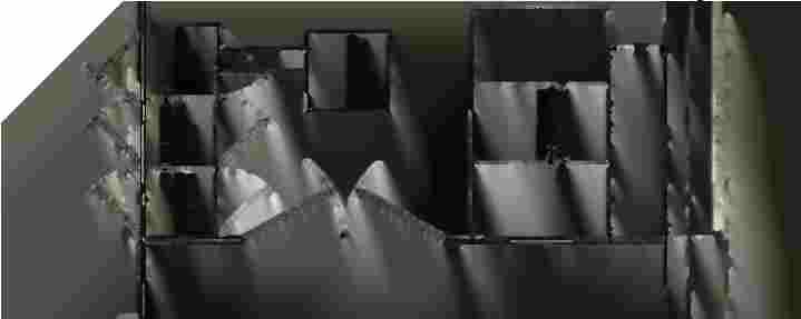
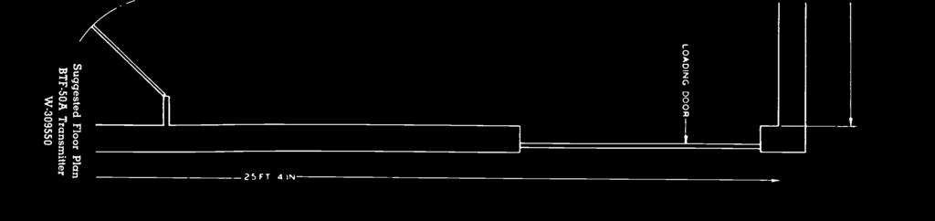
5 transmitter for convenience of d -c and a -c connections. All inter- connections are made in either built - in or over -head ducts, so that the only conduit or trenches required are those for the supervisory console and incoming power. Screen voltage for the low power stages is supplied by a rectifier using one RCA type 5Ú4G, and is located in the low power r -f chassis. CONTROL CIRCUITS High -speed air circuit breakers of the hum free mechanical latch type are employed in all high power switchgear. Overload protection consists of a selective relaying system combining high speed tripping on d -c overloads and short circuit faults, with time delay tripping on nominal a -c system over - current and under voltage faults. The control system is carefully engineered to provide proper starting sequence and automatic protection against most operating faults. Circuit indicator lamps provide a quick means for analyzing and localizing transmitter, tube or line faults, etc. A reclosing system will return full power automatically if the plate voltage is removed due to operation of overload devices on rectifier backfires, vacuum tube gas arcs, antenna flash -overs or other causes. This operation is repeated three times on the high power rectifier. If the fault persists on the third re- application of plate voltage, the recloser will lock out until reset manually. MECHANICAL DESIGN The general arrangement of the transmitter consists of a series of self -supporting chassis in line with a front enclosure to form a unified front panel. A typical floor plan (refer to Dwg. W ) permits installation of the radio frequency portion of the transmitter in a space sixteen and one -half feet long by nine feet deep. With such an arrangement, the blower and power equipment can be installed to suit individual choice and available space as follo rvs:. To the rear of the radio frequency area. 2. In the basement immediately below the R.F. section. 3. The blower on the left hand side of the 50 KW amplifier and the balance of the equipment to the right of the low power R.F. Section. All equipment is dead front constructed, with doors in the front enclosure allowing free access to the driver and P.A. R.F. cabinets and to the transmitter area. With the transmitter "on the air," station personnel can walk behind the enclosure and around the individual units for close inspection. All incoming power supply and high power rectifier switchgear along with lower power distribution circuits, contactors, and control relays are centralized in a single unit. This unit also contains the voltage regulator and distribution transformers. For installation, the transmitter can be broken down into units no larger than thirty by fifty -two and one-hall by eighty inches, with the exception, in height, of enclosure sections, which will be approximately eighty -four inches high. Operational controls, indicating instruments, indicator lights, and tuning controls are located on the front panel at appropriate intervals. Tuning operations required for normal daily adjustments are remotely controlled by front panel key switches controlling motor drives on the tuning elements. P.A. tuning controls are conveniently located with respect to the corresponding meters for easy viewing of D.C. power input and R.F. output during tuning operations. A supervisory control console designed to be set up in a convenient position in front of the transmitter is included as part of the overall operating equipment. Essential operational controls and indicator lamps are duplicated on the R.F. turret of the console. The audio turret of the console has all controls for program handling. Space and mounting convenience has been provided in the R.F. turret for mounting three 4" meters in a recessed position behind the front panel, the choice of the meters being left to the discretion of the station personnel.
6 ANTENNA CUTBACK To provide for continuous broadcast service with a minimum of interruption, antenna cut -back is furnished as standard equipment. A single control switch enables the antenna to be instantly switched from the final amplifier to a lower power r -f amplifier, at approximately the 7 KW level, and at the same time isolates the final amplifier, the driver amplifier, and the high power blower. Final amplifier or driver amplifier tubes may be changed, or necessary servicing done to these units or the high power blower, while program continuity is maintained at the lower power level. Tube changing in the driver and power amplifier stages is facilitated by the use of mechanically operated tube hoist, solidly mounted in a swivel supporting structure and suitably located for easy access to the high power tubes. Two swivel supports are provided. The hoist can be easily lifted from one support to the other, depending upon which tube is to be removed. Lower power tubes are arranged to facilitate tube changing, and a minimum of time required is assured by use of quick opening clamp type filament connectors. The transmitter is completely air cooled. Air cooling for tubes up to the 250 watt level is provided by an exhaust fan and small blowers suitably located to keep cool air circulating. A single blower, mounted external to the R.F. cabinets is used to supply forced air cooling through suitable ducts, to the 7C24 tubes used in the 2nd and 3rd stages and the I.P.A. stage. All cooling mediums have filtered air intakes. Air for the driver and final amplifiers is supplied by a separate blower, having a filtered intake by drawing its air from outside the transmitter area. The heated air from these stages may be exhausted into a manifold for outside delivery, or for heating purposes, if desired. The use of filtered air greatly reduces dust accumulation and increases continuity of service by reduction of associated arcs from dust "pile ups" etc. SAFETY Safety of operating personnel has been given special consideration. All access doors to compartments having high voltage are equipped with automatic interlock switches, so that when any of these doors are opened all rectifiers are de- energized. In addition, the I.P.A., driver and P.A. compartments are equipped with mechanically operated grounding bars which ground the D -C circuits when protective doors are opened. FEATURES Entirely air cooled -no liquid coolant. Simplified single ended circuits throughout. High stability grounded grid amplifiers. Low operating cost -low power input. Conservative operation of all parts and tubes. Built in wiring ducts -minimizes conduit and wire trenches -low installation cost Simplified power supply -only one main rectifier -one screen supply rectifier. Simplified effective control with high speed air circuit breakers. Single phase filament heating of all vacuum tubes. Reduced power operation to a lower powered stage by use of antenna cutback, accomplished by throwing a single switch. Driver and final amplifier serviced or tubes changed while operating with reduced power. Motor driven tuning -essential circuit metering. Breaks down into small units for ease of installation -all units handled by average passenger elevator. Sectional fault indication on front panel enclosure. Protection against transmission line or antenna failure. Attractive appearance achieved by functional styling. Vertical chassis construction for accessibility and ease of ventilation.
 Audio input level for 00% modulation (without pre -emphasis filter)")
 Power line requirements- transmitter line voltage (nominal open circuit) Phase Frequency Total variation below nominal, including regulation Power consumption Power factor Power line")
7 PERFORMANCE SPECIFICATIONS Type of emission Frequency range Power output (into transmission line) R.F. Output impedance Carrier frequency stability, deviation less than Modulation capability Method of modulation Audio input impedance Audio input level for 00% modulation (at input terminals of pre -emphasis network MI- 4926A) Audio input level for 00% modulation (without pre -emphasis filter) Audio frequency response' Audio frequency distortion" 30 to 5,000 cycles (including all harmonics up to 30 KC at 75 KC swing) FM noise level" (below 75 KC swing) AM noise level (below 00% amplitude modulation) Power line requirements- transmitter line voltage (nominal open circuit) Phase Frequency Total variation below nominal, including regulation Power consumption Power factor Power line requirements -crystal heaters Line voltage Phase Frequency Power consumption For pre- emphasis response the pre -emphasis filter (MI- 4926A) Is provided to be most effective point. Distortion and noise are measured following a standard de- emphasis network. TUBE COMPLEMENT Frequency modulation Any specified frequency between 88 to 09 me 0,000 to 50,000 watts 5.5 ohms 000 cycles 00 KC Reactance tubes 600/50 ohms +0-2 dbm -4 -±-2 dbm ± db 30 to 5,000 cycles less than % Not more than -65 db Not more than -50 db From 440 to 480 volts 3 60 cycles (can be adapted for 50 cycles with minor modifications) 5% 25 KW (approximate) 87% (approximate) 5 volts 50/60 cycles 28 watts The following is a list of one complete set of tubes for the BTF -50A Transmitter. For the FM Exciter Modulators Modulated Oscillator st Buffer- Multiplier 2nd Buffer -Multiplier 3rd Buffer- Multiplier st Frequency Divider 2nd Frequency Divider 3rd Frequency Divider 4th Frequency Divider Motor Tubes Crystal Frequency Divider Crystal Oscillator Cathode -Ray Indicator inserted in the 600 ohm audio Input line, at the 2 RCA 6V6 RCA 6V6 RCA 6V6 RCA 2E26 RCA 2E26 RCA 6AC7 RCA 6AC7 RCA 6AC7 RCA 6AC7 4 RCA 64 or 6L6 RCA 6AC7 RCA 6SH7 RCA 2BP
8 For the Exciter Power Supply Low Voltage Rectifier 2 RCA 5U4G High Voltage Rectifier RCA 5U4G Voltage Regulators 2 RCA OD3 /VR50 Voltage Regulator RCA 0C3 /VR05 For the R.F. Units Doubler st R.F. Amplifier 2nd R.F. Amplifier 3rd R.F. Amplifier Intermediate Power Amplifier Driver Amplifier Final Amplifier High Voltage Rectifier Low Voltage Rectifier For Transmission Line Monitor RCA 4D2/4-25A 2 RCA 4D2/4.25A RCA 7C24 RCA 7C24 2 RCA 7C24 RCA RCA RCA 857B RCA 5U4G R.F. Rectifier RCA 6AL5 Thyratron RCA 2D2 R.F. Rectifier RCA 6X5 Mechanical Specifications Refer to floor plan drawing W Equipment Weight Refer to floor plan drawing W Ventilation Requirements Refer to floor plan drawing W EQUIPMENT LIST The BTF -50A Broadcast Transmitter, as herein specified consists of the equipment listed below. Broadcast audio equipment, monitoring and test equipment, antennas and transmission feed line are not furnished as part of this equipment and should be specified and ordered separately if required. The RCA type BTF -50A FM Broadcast Transmitting equipment is identified as MI and consists of the following major items: Item Quantity (See Note 2 ) Description Power Amplifier Unit Power Amplifier R.F. Harness Rectifier Control and Distribution Unit Plate Transformer Filter Reactor Main Blower and Filter Equipment Enclosure and Metal Panel Transmission Line Monitor Harmonic Attenuator Cut Back Equipment FM Exciter Unit Low Power R.F. Units Pre- emphasis Filter (600 ohms) Touch -up Enamel Kit Set of Operating Tubes
 Type BTC -A Supervisory Control Console TMV -29G Crystal Units Instruction Books Set Installation Instructions Installation Material Kit Tube Hoist and Accessories When dual FM")
 TMV -29G crystal units and specify the carrier frequency when ordering.")
9 Note : Note 2: Item Quantity 2 (See Note 2 2 2) Description Blower for 2nd R.F., 3rd R.F. and I.P.A. Units (and air duct) Type BTC -A Supervisory Control Console TMV -29G Crystal Units Instruction Books Set Installation Instructions Installation Material Kit Tube Hoist and Accessories When dual FM exciters are to be specified, order in addition to item =2 above, the spare FM exciter kit MI -705 listed under accessories. Order two (2) TMV -29G crystal units and specify the carrier frequency when ordering. ACCESSORIES (Consult Local RCA Office for Particulars) Spare FM Exciter Unit MI -705 Set of Operating Tubes for Spare FM Exciter MI Modification Kit for 50 cycle Power Source MI Spare Parts On Application Antennas and R.F. Transmission Lines On Application Broadcast Audio Equipment On Application Test and Measuring Equipment On Application INSTALLATION Installation engineering services are not included as a part of this specification but can be furnished separately if required. RCA Service Company of the Radio Corporation of America maintains a staff of broadcast equipment specialists who are available for supervising the station installation, tuning -up the transmitting equipment, and servicing such equipment. CHANGES IN DESIGN In order to make improvements in design and to effect economies in manufacture, the RCA Victor Division of the Radio Corporation of America reserves the right to change the design of its products at any time, and in accordance with its sole judgment, while adhering in good faith to the intent of these specifications.


10

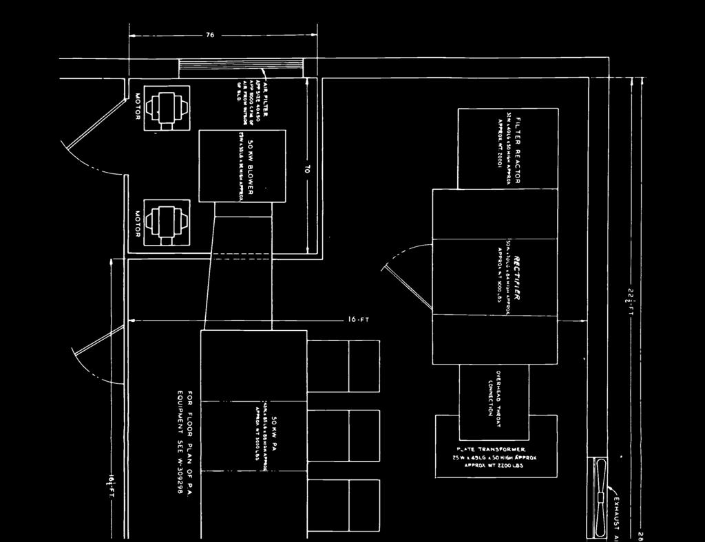

11 76 i T IÓFT P.ATE 'TRANSFORMER. 2Sw i ast.g 50 NIGM irox APPROx r!t 2200 LAS n o 25 FT 4 IN r O v z Ó O r
 ó A o Fi ( p Q to r QDZD -0 - K p")
0 Z o m 0 O m D o = A C món -,m Z")
12 PERCENT o V+ U o 5 o I,7 v J x) ó A o Fi ( p Q to r QDZD -0 - K p p z o -r co fxtl -I Ul M 0 D- < -I (j) 0 Z to (f) --A -73 K 0 -I -A -I o )0 Z o m 0 O m D o = A C món -,m Z Z > 3 Z D xi K Dm


13 80 á '4-it.- To, REMNVE T4BE t No/ST 4 P- o S L _ E MiN. CE/L /03 /Ni NE/ONT 9f i L----J 68«98


14 P co co O, Ñ N N p n P n J S O Pp n? < Co -I co c E < -' m f D c 3vo ás irap '_ o=ñá - co N S x. 3 o Ñ O D 7C 2 Ñ O _. N 0 o o Q = N. O `O vf o a N =' ó ' Cp N CD fd N. ii. O N «in 0 p á S_ N _ o aá o a-,. ' N C A 0 C f v D 0 o N S uoi S? co O D' N T n íwn C O (n!0 N 0 N c. CD O O. - Ó < 3 n n «_ v o VI n ó o ic co - 7C ó ' (o ó A S o n O V, O f.0 O v+ n in c o' 3 E S O x o 3 S o 'T o `< o c o 'O' Á N D < 3 E
BROADCAST FM TELEVISION AM EQUIPMENT AMERICA RADIO CORPORATION OF. ENGINEERING PRODUCTS DEPARTMENT, Camden, N. J., U. S. A.
 BROADCAST FM TELEVISION AM EQUIPMENT RADIO CORPORATION OF AMERICA ENGINEERING PRODUCTS DEPARTMENT, Camden, N. J., U. S. A. 0 KW FM Transmitter Type BTF -0 B Equipment Specification AS-5928 EFFECTIVE JULY,
COLLINS 20T 1000/500 WATT AM BROADCAST TRANSMITTER
 COLLINS 20T 1000/500 WATT AM BROADCAST TRANSMITTER TJIee COLLINS 20T 1 0 0 0 / 5 0 0 W A T T AM BROADCAST TRANSMITTER high fidelity performance low no a and di-tortion vertical chassis construction recycling
GEL, ,000 WATTS GENERAL ELECTRIC
 GEL, 079 50,000 WATTS OF FM GENERAL ELECTRIC Technical Data on New 50,000 -Watt G -E Equipment Installed at Our FM Proving Ground by W. R. DAVID Radio and Television Department GENERAL ELECTRIC COMPANY
By I. R. Baker Station Design
 The New KFI Reproduced from the February 1932 issue of Radio News KFI is now in the super-power class, having recently increased power to 50 Kilowatts the first station west of Texas to use this power.
Continental's 816R -5B, 35 kw Single Tube Broadcast Transmitter. Includes the 802A solid -state exciter
 Continental's 816R -5B, 35 kw Single Tube Broadcast Transmitter Includes the 802A solid -state exciter LED status indicators Features SCR Power Control Automatic RF Power Output Control Automatic SWR Circuit
1 NW BROADCAST TRANSMITTER
 www.americanradiohistory.com 1 NW BROADCAST TRANSMITTER cuit complexities (See Picture 2). Extremely stable low temperature coefficient crystals in conjunction with the highly perfected oscillator design
B R O A D C A S T TRANSM' EQUI P M E N T FOR AM FM RADIO (THIRD EDITION)
") B R O A D C A S T TRANSM' EQUI P M E N T FOR AM FM RADIO (THIRD EDITION) www.americanradiohistory.com www.americanradiohistory.com BROADCAST AM -FM TRANSMITTING EQUIPMENT CATALOG FM Transmitters Multiplex
B R O A D C A S T TRANSM' EQUI P M E N T FOR AM FM RADIO (THIRD EDITION) www.americanradiohistory.com www.americanradiohistory.com BROADCAST AM -FM TRANSMITTING EQUIPMENT CATALOG FM Transmitters Multiplex
I :NO 1111Z7 :4 TRANSMITTERS PHASING MONITORING TOWERS LINES TRANSMITTING EQUIPMENT
 I :NO 1111Z7 :4 TRANSMITTERS PHASING MONITORING TOWERS LINES TRANSMITTING a 0 EQUIPMENT AM RADIO TRANSMITTING EQUIPMENT CATALOG THE MOST TRUSTED NAME IN ELECTRONICS Copyright 1967 Radio Corporation of
5/1.0 kw AM Transmitter
 5/1.0 kw AM Transmitter Collins' 820E /F -1 series of broadcast transmitters is one of the most extensively transistorized series of transmitters available in the 5 -kw to 10 -kw power range. The series
TECHNICAL DESCRIPTION
 TECHNICAL DESCRIPTION A.M. BROADCAST TRANSMITTER SENDER AM 3000 SS June 2001-1- Rev. B TRANSMITTER CHARACTERISTICS 1. BASIC OFFER The basic offer includes: One AM3000SS A.M. Medium Wave Solid State Broadcast
KWM-2/2A Transceiver THE COLLINS KWM-2/2A TRANSCEIVER
 KWM-2/2A Transceiver Click the photo to see a larger photo Click "Back" button on browser to return Courtesy of Norm - WA3KEY THE COLLINS KWM-2/2A TRANSCEIVER Unmatched for versatility, dependability and
9007 Power Tube. VHF Linear Power Amplifier Tube 33 Kilowatt Peak Sync Output Thru VHF-TV Band
 9007 Power Tube VHF Linear Power Amplifier Tube 33 Kilowatt Peak Sync Output Thru VHF-TV Band 14 db Gain High Gain-Bandwidth Products Efficient Forced-Air Cooling Full Input to 400 MHz CERMOLOX Construction
1 KW TOTALLY SOLID STATE DIFFERENTIAL GPS TRANSMITTER ( khz)
") GPS1000 1 KW TOTALLY SOLID STATE DIFFERENTIAL GPS TRANSMITTER (282-326 khz) NAUTEL has developed the GPS1000 as an extremely efficient and highly reliable transmitter especially suited for use at remote
GPS1000 1 KW TOTALLY SOLID STATE DIFFERENTIAL GPS TRANSMITTER (282-326 khz) NAUTEL has developed the GPS1000 as an extremely efficient and highly reliable transmitter especially suited for use at remote
POWER DELEGATOR SERIES 7200A POWER DISTRIBUTION UNIT WITH POWER CONDITIONING GENERAL SPECIFICATIONS
 POWER DELEGATOR SERIES 7200A POWER DISTRIBUTION UNIT WITH POWER CONDITIONING GENERAL SPECIFICATIONS 1.0 SCOPE The following specification describes the features, design, and application of the Series 7200A
A 75-Watt Transmitter for 3 Bands Simplified Shielding and Filtering for TVI BY DONALD H. MIX, W1TS ARRL Handbook 1953 and QST, October 1951
 A 75-Watt Transmitter for 3 Bands Simplified Shielding and Filtering for TVI BY DONALD H. MIX, W1TS ARRL Handbook 1953 and QST, October 1951 The transmitter shown in the photographs is a 3-stage 75-watt
LBI-30398N. MAINTENANCE MANUAL MHz PHASE LOCK LOOP EXCITER 19D423249G1 & G2 DESCRIPTION TABLE OF CONTENTS. Page. DESCRIPTION...
 MAINTENANCE MANUAL 138-174 MHz PHASE LOCK LOOP EXCITER 19D423249G1 & G2 LBI-30398N TABLE OF CONTENTS DESCRIPTION...Front Cover CIRCUIT ANALYSIS... 1 MODIFICATION INSTRUCTIONS... 4 PARTS LIST AND PRODUCTION
ERICSSONZ LBI-30398P. MAINTENANCE MANUAL MHz PHASE LOCKED LOOP EXCITER 19D423249G1 & G2 DESCRIPTION TABLE OF CONTENTS
 MAINTENANCE MANUAL 138-174 MHz PHASE LOCKED LOOP EXCITER 19D423249G1 & G2 TABLE OF CONTENTS Page DESCRIPTION... Front Cover CIRCUIT ANALYSIS...1 MODIFICATION INSTRUCTIONS...4 PARTS LIST...5 PRODUCTION
8988 Power Tube. Linear Beam Power Tube
 8988 Power Tube Linear Beam Power Tube CERMOLOX Tube High Gain-Bandwidth Product Full Input to 400 MHz 7000 W Peak Sync. Output Through VHF-TV Band with 16 db Gain The BURLE 8988 is designed specifically
FREQUENCY AGILE FM MODULATOR INSTRUCTION BOOK IB
 FMT615C FREQUENCY AGILE FM MODULATOR INSTRUCTION BOOK IB1215-02 TABLE OF CONTENTS SECTION SUBJECT 1.0 Introduction 2.0 Installation & Operating Instructions 3.0 Specification 4.0 Functional Description
8121 Power Tube. Linear Beam Power Tube
 8121 Power Tube Linear Beam Power Tube Coaxial-Electrode Structure Ceramic-Metal Seals Full Ratings up to 500 MHz Forced-Air Cooled 170 Watts PEP Output at 30 MHz 235 Watts CW Output at 470 MHz The BURLE
WLW 500 KW Transmitter Manual
 WLW 500 KW Transmitter Manual Table of Contents 5.00 ANALYSIS OF OPERATION - POWER RF AND AUDIO CIRCUITS 5.01 General 5.02 2300 Volt AC Circuits 5.021 Main Rectifier 5.022 Filament M-G Motors 5.03 220-Volt
GRID CONTROLLED POWER SUPPLY IS A VERSATILE UNIT Uses Pair of RCA-2050 s for Wide Voltage Range
 10/30/07 11:55 PM Thyratrons GRID CONTROLLED POWER SUPPLY IS A VERSATILE UNIT Uses Pair of RCA-2050 s for Wide Voltage Range By J. H. OWENS, W2FTW and G. D. HANCHETT, W1AK/2 RCA Ham Tips Volume 6, Number
8984 Power Tube. VHF Linear Beam Power Tube
 8984 Power Tube HF Linear Beam Power Tube Full Input to 300 MHz Forced-Air Cooled 55 kw Peak Sync. Output HF-T Band 16dB Gain FM Broadcast Service 55 kw Output 16dB Gain The BURLE 8984 is designed specifically
Central Electronics Model 600L Linear Amplifier
 INTRODUCTION This manual has been reproduced by James Lawrence, NA5RC, a 600L owner. Text no longer applicable such as insurance claim with the carrier has been deleted. Some capitalization and grammar
Power Tube. Beam Power Tube
 8977 Power Tube Beam Power Tube - 7 kw Aural Output Through VHF-TV Band - 19 db Gain - CERMOLOX Beam Power Tube - Full Input to 400 MHz - Forced-Air Cooled The BURLE 8977 is intended specifically to meet
BROADCAST TRANSMITTER
 -- TRANSMITTI`VGAQ U I PME NT MODEL BC -1E BROADCAST TRANSMITTER 1000 WATTS HIGH LEVEL MODULATION Here is a 1000 watt transmitter that is better than has heretofore been offered. Outstanding among its
RADIO ENGINEERING LABORATORIES, INC. STATION W398 NEW "DL"" LINE OF FM TRANSMITTERS. using YANKEE NETWORK
 YANKEE NETWORK STATION W398 using NEW "DL"" LINE OF FM TRANSMITTERS COMPLETE FREQUENCY MODULATION TRANSMITTER INSTALLATIONS FOR STATIC -FREE, HIGH-FIDELITY BROADCASTING AND COMMUNICATIONS -250 WATTS TO
Figure Cutaway view of the Phasitron tube, which is used as the modulator and upon which the operation of the GE f-m transmitter is based.
 FM Transmission and Reception Pages 130-135 Rider, John. F., and Seymour D. Uslan John F. Rider Publisher, Inc., 1948. THE GENERAL ELECTRIC TRANSMITTER The original f-m transmitters manufactured by the
LBI-4938C. Mobile Communications MASTR II POWER AMPLIFIER MODELS 4EF4A1,2,3. Printed in U.S.A. Maintenance Manual
 C Mobile Communications MASTR II POWER AMPLIFIER MODELS 4EF4A1,2,3 Printed in U.S.A. Maintenance Manual TABLE OF CONTENTS DESCRIPTION.................................................... 1 CIRCUIT ANALYSIS.................................................
Western Electric 106 -A AMPLIFIER INSTRUCTION BULLETIN NO. 880, ISSUE NO. 2
 Western Electric 106 -A AMPLIFIER INSTRUCTION BULLETIN NO. 880, ISSUE NO. 2 Western Electric 106 -A AMPLIFIER Type Two -stage line or main Amplifier with bridging or matching input. A complete self -contained
TQCYkDi. HARRIS AND COMMUNICATIONS INFORMATION HANDLING
 TQCYkDi RTaa3CM(M@TZ a@21210.tiq_i@z W COMMUNICATIONS AND INFORMATION HANDLING INTRODUCTION The Harris Corporation - Broadcast Products Division proudly presents its first catalog devoted exclusively to
2 5 1 A Va c u u m T u b e
 251A 2 5 1 A Va c u u m T u b e P L A T E L E A D INSULATORS W SPRING CONNECTOR - P L A T E L E A D -FILAMENT LEADS CONNECTOR GRID LEAD Classification The 251A Vacuum Tube is a three element, air-cooled,
PLUG N PLAY WATT DIGITAL FM TRANSMITTER. April, 2002 IM No
 PLUG N PLAY 1000 1000 WATT DIGITAL FM TRANSMITTER April, 2002 IM No. 597 9972 OPERATION/FEATURE PROGRAMMING. The PNP 1000 allows the user to select many types of different operating parameters and features.
Western E/ectrk A V a c u u m T u b e
 295A Western E/ectrk 2 9 5 A V a c u u m T u b e Classification Filamentary air- cooled triode May be used as an audio-frequency amplifier or as a radio-frequency amplifier, modulator o r o s c i l l a
MODEL PD PEARSON DETECTOR
 MODEL PD PEARSON DETECTOR FIVE SECTIONS of QUICK INFORMATION I. Model PD Functions II. Operation Methods III. Apparatus IV. Instructions for Unpacking & Inspection V. Operating Instructions TINKER & RASOR
Broadcast Transmitter
 . i I Broadcast Transmitter Type -C Output Kilowatt RCA Victor Company, Inc. Camden, N. J., U. S. A. l RCA Broadcast Transmitter Type -C Output Kilowatt INSTRUCTIONS RCA Victor Company, Inc. Camden, N.
Broadcast Systems. Radio. Equipment. AM Transmitters FM Transmitters Exciters, Monitors STL, Remote Control Transmission Line Antennas, Towers
 Broadcast Systems Radio Equipment AM Transmitters FM Transmitters Exciters, Monitors STL, Remote Control Transmission Line Antennas, Towers Roil Contents About This Catalog This is one of several catalogs
PA FAN PLATE ASSEMBLY 188D6127G1 SYMBOL PART NO. DESCRIPTION. 4 SBS /10 Spring nut. 5 19A702339P510 Screw, thread forming, flat head.
 MAINTENANCE MANUAL 851-870 MHz, 110 WATT POWER AMPLIFIER 19D902797G5 TABLE OF CONTENTS Page DESCRIPTION.............................................. Front Page SPECIFICATIONS.................................................
8072 Power Tube. VHF Linear Amplifier Tube. Coaxial-Electrode Structure Ceramic-Metal Seals Full Input to 500 MHz Conduction Cooled
 8072 Power Tube VHF Linear Amplifier Tube Coaxial-Electrode Structure Ceramic-Metal Seals Full Input to 500 MHz Conduction Cooled The BURLE 8072 is a small, conduction cooled beam power tube designed for
INSTRUCTIONS FOR INSTALLATION AND OPERATION OF THE MEISSNER SIGNAL SHIFTER MODEL EX
 INSTRUCTIONS FOR INSTALLATION AND OPERATION OF THE MEISSNER SIGNAL SHIFTER MODEL EX I. INTRODUCTION A. The MEISSNER SIGNAL SHIFTER is a variable frequency exciter, with output over the entire ranges of
.w :16"12- FM Transmitter, 40kIN, Type BTF-40ES1. catalog RA.2071E MEI IM M1 MTh C) 0 Aims E1 sou Q *so
 0 Aims E1 sou Q *so") catalog RA.2071E (Replaces RA.2071D) FM Transmitter, 40kIN, Type BTF-40ES1 r Parallel Transmitters for Ai( The Type BTF-40ES1 is a forty -kilowatt transmitter for the maximum - power FM -broadcast station
catalog RA.2071E (Replaces RA.2071D) FM Transmitter, 40kIN, Type BTF-40ES1 r Parallel Transmitters for Ai( The Type BTF-40ES1 is a forty -kilowatt transmitter for the maximum - power FM -broadcast station
J kw AM Transmitter
 J1000 1 kw AM Transmitter J1000 1 kw AM Transmitter J1000 1kW AM Transmitter GREAT THINGS REALLY DO COME IN SMALL PACKAGES. The J1000 transmitter provides excellent functionality and flexibility for the
Filament Thoriated tungsten. Filament voltage...14 volts Nominal filament current... 6 amperes Average thermionic emission...
 Classification Filamentary Air-cooled Triode. Application May be used as an audio-frequency amplifier or modulator; or as a radiofrequency oscillator or amplifier. Dimensions Large four-pin bayonet base
51J-4 COMMUNICATIONS RECEIVER
 51J-4 COMMUNICATIONS RECEIVER Transcribed from 520-5014-00 August 15, 1954 GENERAL DESCRIPTION The Collins 51J-4 Receiver is designed for communication applications where stability and dial accuracy of
Distribution/Substation Transformer
 Distribution/Substation Transformer Type VFI, Vacuum Fault Interrupter Transformer Option Functional Specification Guide Functional specification for 15 kv, 25 kv, or 35 kv vacuum fault interrupter distribution/substation
8807 Power Tube. Beam Power Tube
 8807 Power Tube Beam Power Tube CERMOLOX Beam Power Tube Full Input to 400 MHz Forced-Air-Cooled 17.6 kw Peak Sync Output VHF-TV Band 13 db Gain Single Sideband 15 kw PEP 20 db Gain FM Broadcast Service
MEDIUM-MU AIR-COOLED POWER TRIODE 3CX15,000H3
 TECHNICAL DATA MEDIUM-MU AIR-COOLED POWER TRIODE 3CX15,000H3 The EIMAC 3CX15,000H3 is an air cooled, ceramic-metal, medium-mu power triode designed primarily for use in broadcast and industrial radio-frequency
Western Electric D V a c u u m T u b e
 284D Western Electric 2 8 4 D V a c u u m T u b e Classification Fiiamentary air-cooied triode The tube is designed primarily for use as an audio-frequency amplifier or modulator and may be used as a replacement
BROADCAST EQUIPMENT 19fí2
 BROADCAST EQUIPMENT 19fí2 The reputation of Collins Radio Company has been built on more than a quarter of a century of research, development and manufacture of distinctive electronic equipment. To assure
Each module of the AN/ARC-34 has a special 9-pole test connector to check the B+ voltages, filament voltage, and oscillator negative grid voltages.
 ARC-34 Testpoints Each module of the AN/ARC-34 has a special -pole test connector to check the B+ voltages, filament voltage, and oscillator negative grid voltages. These are measured with the URM-A voltmeter
Nautel Limited FM 3.5 kw, 5 kw, 8 kw Totally Solid State FM Broadcast Transmitters
 RUGGED SOLID STATE MODULAR DESIGN No tubes to replace No routine tuning or adjustments 65% typical overall efficiency NAUTEL PATENTED COMBINING TECHNIQUE Failure isolation between PA's Multiple power amplifier
SGMF(T) series. Onsite Mobile AC High Voltage Test System. Applications:
 series. Onsite Mobile AC High Voltage Test System. Applications:") SGMF(T) series Onsite Mobile AC High Voltage Test System On-site AC high voltage test systems are used for voltage withstanding test, partial discharge measurement, tan delta measurement on those instrument
SGMF(T) series Onsite Mobile AC High Voltage Test System On-site AC high voltage test systems are used for voltage withstanding test, partial discharge measurement, tan delta measurement on those instrument
XR kw AM Medium Wave Broadcast Transmitter
 XR12 12 kw AM Medium Wave Broadcast Transmitter XR12 12 kw AM Medium Wave Broadcast Transmitter XR Series Power Module POWERFUL BUILDING BLOCKS The building block for the XR12 is a power module integrating
1. SYSTEM DESCRIPTION NON - DIRECTIONAL RADIO BEACON TRANSMITTER (NDB) JTM-30C
 JTM-30C") Documentation Rev.Date Rev. Document no. 1. SYSTEM DESCRIPTION NON - DIRECTIONAL RADIO BEACON TRANSMITTER (NDB) JTM-30C 1. SYSTEM DESCRIPTION... 2 1.1 OVERALL SYSTEM DESCRIPTION... 2 1.2 BASIC MODULES...
Documentation Rev.Date Rev. Document no. 1. SYSTEM DESCRIPTION NON - DIRECTIONAL RADIO BEACON TRANSMITTER (NDB) JTM-30C 1. SYSTEM DESCRIPTION... 2 1.1 OVERALL SYSTEM DESCRIPTION... 2 1.2 BASIC MODULES...
INSTALLATION, OPERATION AND MAINTENANCE GUIDE
 INSTALLATION, OPERATION AND MAINTENANCE GUIDE FOR INDOOR/OUTDOOR SINGLE PHASE ENCAPSULATED TRANSFORMERS Indoor/Outdoor Encapsulated Transformers The pictures used in this guide are only a representation
Numbering System for Protective Devices, Control and Indication Devices for Power Systems
 Appendix C Numbering System for Protective Devices, Control and Indication Devices for Power Systems C.1 APPLICATION OF PROTECTIVE RELAYS, CONTROL AND ALARM DEVICES FOR POWER SYSTEM CIRCUITS The requirements
Technician Licensing Class. Lesson 4. presented by the Arlington Radio Public Service Club Arlington County, Virginia
 Technician Licensing Class Lesson 4 presented by the Arlington Radio Public Service Club Arlington County, Virginia 1 Quiz Sub elements T6 & T7 2 Good Engineering Practice Sub element T8 3 A Basic Station
SINGLE PHASE BUCK & BOOST TRANSFORMERS INSTRUCTION MANUAL
 SINGLE PHASE INSTRUCTION MANUAL DIAGRAM D This manual applies to all single-phase buck & boost transformers sold by Larson Electronics. Please refer to the connection diagram on pages 4-6 for properly
Technical Equipment Specification
 STATE OF CALIFORNIA Office of the State Chief Information Officer Public Safety Communications Division Technical Equipment Specification Equipment Type: Transmitter/Receiver Mobile Relay/Base/Control
780-8 Series Constant Impedance FM Combiners
 Features Cylindrical construction provides better mechanical and electrical stability than square or rectangular cavities Factory tuned to customer s specified channel, yet can be easily field converted
Power Processor - Series 700F 10KVA to 150KVA
 Power Processor - Series 700F 10KVA to 150KVA Power Conditioning and Regulation for Commercial & Industrial Equipment General Specifications PART 1 - GENERAL 1.1 DESCRIPTION This specification defines
NA100 NA200 NA300. NA Series Frequency Agile Medium Wave Broadcast Transmitters
 NA100 NA200 NA300 NA Series Frequency Agile Medium Wave Broadcast Transmitters Making Digital Radio Work. Nautel NA100, NA200 & NA300 Quick Specs Field tunable to any frequency in the medium wave band
Onsite Mobile AC High Voltage Test System
 TSGMF(T) series Onsite Mobile AC High Voltage Test System Onsite mobile AC high voltage test systems are used for withstand voltage testing, partial discharge measurement, tan delta measurement to instrument
PL8877/ 3CX1500A7 High-Mu Power Triode
 PL8877/ 3CX1500A7 High-Mu Power Triode The Penta Laboratories PL8877/3CX1500A7 is a rugged ceramic and metal power triode designed for use as cathode driven Class AB2 or Class B amplifi er in audio or
EDACS WALL MOUNT STATION. Maintenance Manual. Mobile Communications LBI-31838A TABLE OF CONTENTS
 A Mobile Communications EDACS WALL MOUNT STATION TABLE OF CONTENTS SYSTEM BOARD & REGULATOR BOARD.......... LBI-31892 KEY/DISPLAY BOARD MAINTENANCE MANUAL.... LBI-31940 Maintenance Manual Printed in U.S.A.
Frequency range: BAND RANGE MHz MHz
 INSTRUCTION SHEET NO. 20 POWER-MITE PM3 and PM3A DESCRIPTION The Power-Mite 3 and 3A are self-contained CW transceivers covering 40 and 20 meters. The receiver is compromised of a variable oscillator operating
PET1606J2F. Pilani Electron Tubes & Devices Pvt. Ltd. Water Cooled Triode. For Industrial RF Heating. Drop in equivalent of BW1606J2F
 Water Cooled Triode For Industrial RF Heating Drop in equivalent of BW1606J2F Output Power: 30 kw Anode voltage: 10 kv max Anode dissipation: 15 kw max Frequency up to 30 MHz Manufactured in India, in
Instruction Manual OM3500 HF SHORTWAVE POWER AMPLIFIER. OM POWER, s. r. o Bác 126 SLOVAKIA
 Instruction Manual OM3500 HF SHORTWAVE POWER AMPLIFIER OM POWER, s. r. o. 930 30 Bác 126 SLOVAKIA Important safety instructions: The amplifier contains high voltage circuits. Never turn the amplifier on
SECTION LOW VOLTAGE ACTIVE HARMONIC FILTER SYSTEM NEMA 1 ENCLOSED
 SECTION 16280 LOW VOLTAGE ACTIVE HARMONIC FILTER SYSTEM NEMA 1 ENCLOSED PART 1 - GENERAL 1.1 SUMMARY This specification defines the requirements for active harmonic filter systems in order to meet IEEE-519-2014
RADIAL BEAM POWER CPI RADIAL 4CW50,000J BEAM POWER TETRODE 4CX20,000C
 The EIMAC is a ceramic/metal power tetrode intended for use as a VHF power amplifier. It features a type of internal mechanical structure which results in high rf operating efficiency. Low rf losses in
Laboratory Grade Instruments Series & 4021 Power Meter SERIES Power Sensor
 Laboratory Grade Instruments 4020 Series & 4021 Power Meter Semiconductor 4020 SERIES Power Sensor 4021 4022 4024 4025 Power Input 300 mw to 1 kw 300 mw to 1 kw 3 W to 10 kw 3 W to 10 kw (1.2 kw max.)
MAINTENANCE MANUAL TRANSMITTER/RECEIVER BOARD CMN-234A/B FOR MLSU141 & MLSU241 UHF MOBILE RADIO TABLE OF CONTENTS
 MAINTENANCE MANUAL TRANSMITTER/RECEIVER BOARD CMN-234A/B FOR MLSU141 & MLSU241 UHF MOBILE RADIO TABLE OF CONTENTS DESCRIPTION... 2 CIRCUIT ANALYSIS... 2 TRANSMITTER... 2 9-Voft Regulator... 2 Exciter...
MASTR II AUXILIARY RECEIVER 19D417546G7 & G8 & ANTENNA MATCHING UNITS 19C321150G1-G2. Maintenance Manual LBI-30766L. Mobile Communications
 L Mobile Communications MASTR II AUXILIARY RECEIVER 19D417546G7 & G8 & ANTENNA MATCHING UNITS 19C321150G1-G2 Printed in U.S.A Maintenance Manual TABLE OF CONTENTS Page SPECIFICATIONS.....................................................
Maintenance Manual TRANSMITTER/RECEIVER BOARD CMN-233 FOR MLSH041
 Maintenance Manual TRANSMITTER/RECEIVER BOARD CMN-233 FOR MLSH041 TABLE OF CONTENTS Page DESCRIPTION... 2 CIRCUIT ANALYSIS... 2 Transmitter... 2 9-volt Regulator... 2 Exciter... 2 40-Watt PA... 2 Antenna
A 100-Watt Transmitter Using a Pair of VT1625s
 12/16/2007 6:00 PM VT1625 100 Watt Transmitter A 100-Watt Transmitter Using a Pair of VT1625s FIG. 10.6 A 100-watt transmitter for five bands, using salvaged TV power transformer and surplus 1625 amplifier
Maintenance Manual. MTD SERIES 900 MHz, 10-WATT, DATA ONLY MOBILE RADIO. Mobile Communications LBI TABLE OF CONTENTS
 Mobile Communications MTD SERIES 900 MHz, 10-WATT, DATA ONLY MOBILE RADIO TABLE OF CONTENTS RF BOARD............................... LBI-38545 AUDIO BOARD............................ LBI-38546 LOGIC BOARD............................
Maintenance Manual LBI-38531G MHz, 110 WATT POWER AMPLIFIER 19D902797G1 DESCRIPTION TABLE OF CONTENTS
 Maintenance Manual LBI-38531G 136-174 MHz, 110 WATT POWER AMPLIFIER 19D902797G1 TABLE OF CONTENTS Page DESCRIPTION.............................................. Front Cover SPECIFICATIONS.................................................
SECTION NEUTRALIZATION BELOW VHF NEUTRALIZATION
 SECTION 5 NEUTRALIZATION A completely neutralized amplifier must fulfill two conditions. The first is that the interelectrode capacitance between the input and output circuits be cancelled. The second
4-400C/6775 Radial Beam Power Tetrode
 Radial Beam Power Tetrode The Amperex 4-400C/6775 is a compact, ruggedly constructed, broadcast quality tetrode having a maximum plate dissipation rating of 400 watts. It is intended for use as an amplifier,
LIFE LINE PRODUCT SPECIFICATION FOR A 1 TO 3 KVA, SINGLE PHASE, POWER DISTRIBUTION SYSTEM WITH REGULATION AND CONDITIONING
 LIFE LINE PRODUCT SPECIFICATION FOR A 1 TO 3 KVA, SINGLE PHASE, POWER DISTRIBUTION SYSTEM WITH REGULATION AND CONDITIONING 1.0 General This specification covers the electrical characteristics and general
FMR622S DUAL NARROW BAND SLIDING DE-EMPHASIS DEMODULATOR INSTRUCTION BOOK IB
 FMR622S DUAL NARROW BAND SLIDING DE-EMPHASIS DEMODULATOR INSTRUCTION BOOK IB 1222-22 TABLE OF CONTENTS SECTION 1.0 INTRODUCTION 2.0 INSTALLATION & OPERATING INSTRUCTIONS 3.0 SPECIFICATIONS 4.0 FUNCTIONAL
Western Electric PRII URAM AMPLIFIER 11H A
 Western Electric PRII URAM AMPLIFIER s 11H A HIKE WORII The part played by Bell Telephone Laboratories and by Western Electric in radio telephone broadcasting is the history of the radio art. In 1922 a
Instructions MODIFICATION KIT MODEL SBM - 1O2-1 INTRODUCTION PARTS LIST FOR THE
 Instructions FOR THE MODIFICATION KIT MODEL SBM - 1O2-1 INTRODUCTION This modification Kit applies to the following Heath Transceivers: 1. All Models HW-100, SB-100, SB-101 and SB-101W. 2. Any Model SB-102
Variable Frequency Drive Packages with Harmonic Mitigation. Low Harmonic Drive Packages Engineered by Rockwell Automation
 Variable Frequency Drive Packages with Harmonic Mitigation Low Harmonic Drive Packages Engineered by Rockwell Automation What Do I Need to know About Harmonics? What are Harmonics? Harmonics are deviations
FMQ-20KWC/FMQ-30KWC 20/30 KW FM TRANSMITTER
 FMQ-20KWC/FMQ-30KWC 20/30 KW FM TRANSMITTER INSTALLATION AND OPERATIONS MANUAL DESIGNED AND MANUFACTURED BY QEI CORPORATION P.O. BOX 805 WILLIAMSTOWN, NJ 08094 USA 856-728-2020 856-629-1751 (Fax) qeisales@qei-broadcast.com
2 5 4 A V a c u u m T u b e
 V a c u u m T u b e 2 5 4 A V a c u u m T u b e Classification The No. 254A Vacuum Tube is a four-element, screen-grid tube for use as a radio-frequency power-amplifier and as a harmonic-generator at intermediate
LPF-100 Composite Low Pass Filter
 Broadcast Devices, Inc. LPF-00 Composite Low Pass Filter TECHNICAL REFERENCE MANUAL Broadcast Devices, Inc. 0 E. Main Street Cortlandt Manor, NY 07 Tel. (94) 77-0 Fax. (94) 7-9 REV: A 0/09 Table of Contents
WARNING: DO NOT PROCEED WITHOUT READING THIS PAGE.
 WARNING: DO NOT PROCEED WITHOUT READING THIS PAGE. The B-1030-G produces at least 300 watts of VHF R.F. power and is not to be taken lightly. Severe R.W. burns can be sustained at this power level! Power
Electric. Western AMPLIFIER. Cu'eljr-rva INSTRUCTIONS. Printed in U.S.A. Instruction Bulletin No. 728
 Western Electric RADIO FREQUENCY AMPLIFIER No. 6071 B Cu'eljr-rva INSTRUCTIONS FOR USE Printed in U.S.A. Instruction Bulletin No. 728 The equipment described in this Bulletin was designed and developed
Western electric 450A4 AND 451A -1 RADIO TRANSMITTING EQUIPMENTS. Instruction Bulletin No. 988P
 Western electric 450A4 AND 451A -1 RADIO TRANSMITTING EQUIPMENTS Instruction Bulletin No. 988P , 450A -1 AND 451A -1 RADIO TRANSMITTING EQUIPMENTS Instruction Bulletin No. 988P 450A -1 AND 451A -1 RADIO
PET1610F. Pilani Electron Tubes & Devices Pvt. Ltd. Forced-Air Cooled Triode. For Industrial RF Heating. Drop in equivalent of BW1610F
 Forced-Air Cooled Triode For Industrial RF Heating Drop in equivalent of BW1610F Output Power: 30 kw Anode voltage: 9 kv max Anode dissipation: 10 kw max Frequency up to 30 MHz Manufactured in India, in
RF Power Amplifier (RFPA) Designing a 'Output Tank Circuit'
 Designing a 'Output Tank Circuit'") RF Power Amplifier (RFPA) Designing a 'Output Tank Circuit' By Larry E. Gugle K4RFE, RF Design, Manufacture, Test & Service Engineer (Retired) Figure-1 Output 'Tank' Circuit Network in Low-Pass Filter
RF Power Amplifier (RFPA) Designing a 'Output Tank Circuit' By Larry E. Gugle K4RFE, RF Design, Manufacture, Test & Service Engineer (Retired) Figure-1 Output 'Tank' Circuit Network in Low-Pass Filter
Solid State General Communication Power Amplifier
 The GCS1D2GUT (SKU 4062) is suitable for broadband high power linear applications in the HF frequency range. This rack mount amplifier utilizes pushpull MOSFET power devices that provide high gain, wide
DLVP A OPERATOR S MANUAL
 DLVP-50-300-3000A OPERATOR S MANUAL DYNALOAD DIVISION 36 NEWBURGH RD. HACKETTSTOWN, NJ 07840 PHONE (908) 850-5088 FAX (908) 908-0679 TABLE OF CONTENTS INTRODUCTION...3 SPECIFICATIONS...5 MODE SELECTOR
WARNING: DO NOT PROCEED WITHOUT READING THIS PAGE.
 WARNING: DO NOT PROCEED WITHOUT READING THIS PAGE. The B-2530-G produces at least 300 watts of VHF R.F. power and is not to be taken lightly. Severe R.W. burns can be sustained at this power level! Power
Svetlana 4CX7500A Radial Beam Power Tetrode
 Svetlana CX7500A Radial Beam Power Tetrode T he Svetlana CX7500A is designed for audio and radio frequency applications. The Svetlana CX7500A has a directly-heated thoriated tungsten mesh filament for
18-CHANNEL MOBILE CB TRANSCEIVER MODEL CB-845
 18-CHANNEL MOBILE CB TRANSCEIVER MODEL CB-845 INSTRUCTION HANDBOOK RAll JEFFERSOn CITIZEN BAND RADIO MESSAGE TO THE OWNER CONGRATULATIONS! As the new owner of Ray Jefferson Model CB-845 CB Mobile Transceiver,
READ THIS BEFORE ATTEMPTING TO COMBINE
 HANDBOOK FM SERIES 2000W POWER COMBINER READ THIS BEFORE ATTEMPTING TO COMBINE 4 s PTEK Contents Theory of operation...2 Specifications...3 Safety Notice...4 Rear Panel Layout...5 Installation...8 Schematic
SOUTHERN AVIONICS COMPANY. SE125 Transmitter. SE125 Transmitter 1-1
 1-1 1 Introduction The SE Series transmitters are computer controlled systems designed around an embedded microprocessor. These systems are capable of remote monitoring and maintenance via Ethernet (optional).
RADIO BROADCAST EQUIPMENT
 RADIO BROADCAST EQUIPMENT r 24 HOUR PROFESSIONAL SERVICE FOR AM 8 FM TRANSMITTERS PARTS (214)327-4532 SERVICE (214)327-4533 SALES (214)381-7161 www.americanradiohistory.com INTRODUCTION tif:7"1- fi...;6m`