RADIO BROADCAST EQUIPMENT
|
|
|
- Diane Gardner
- 5 years ago
- Views:
Transcription


1 RADIO BROADCAST EQUIPMENT r 24 HOUR PROFESSIONAL SERVICE FOR AM 8 FM TRANSMITTERS PARTS (214) SERVICE (214) SALES (214)

2


3 INTRODUCTION tif:7"1- fi...;6m` r Pff t Introduction Continental Electronics Mfg. Co. is an engineering- oriented company that specializes in the design, development and production of low, medium and high power radio frequency transmitters for radio broadcast, communications, radar and scientific research applications. The company was founded in 1946 with the express purpose of creating an extensive capability in rf product design. Since its founding, Continental has established an unmatched record of achievement in the area of high power rf transmitters and amplifiers. Many of the Company's innovations have advanced the state -of -the -art; most of its work has been of a pioneering type and the kind of work normally associated with the leading edge of technology. C 1981 Continental Electronics Mfg. Co. Continental's commitment to excellence is reflected in the workmanship and operational performance of numerous radio /electronic products which bridge the spectrum from ELF to UHF, ranging in power from kilowatts to megawatts. Continental broadcast transmitters are used throughout the world by commercial and government radio stations for local, regional and international broadcasting. In addition to high power and short wave transmitters, Continental offers broadcasters a complete line of AM and FM transmitters from 1,000 watts to 50,000 watts; combiners, diplexers, phasing, coupling and antenna systems and related rf equipment. / y This catalog gives a brief product overview of the radio broadcast equipment available from Continental. For performance data, specifications, pricing and delivery information, contact your local Continental sales representative. All products and prices in this catalog are subject to change without notice; all products are subject to prior sale; no warranty or guarantee as to product availability or performance is given or implied. 1


4 TABLE OF CONTENTS Introduction 1 Table of contents 2 Transmitters FM Transmitters 2.5 & 1.25 kw 6 10 kw 8 25 &20 kw &40 kw 12 Automatic Exciter Control 12 Automatic Transmitter Combiner Control 12 Exciter 14 AM Transmitters 1 kw 16 5 kw kw kw 22 High -power broadcast transmitters 150 & 100 kw kw kw 28 1,000 kw 30 2,000 kw 32 SW Transmitters 10 kw kw kw kw 40 Transmitter Combiners 42 Transmitter Dummy Loads 44 Antenna systems and accessories AM & FM Zbwers 48 Antenna Phasing & Coupling 49 FM Antennas 53 Antenna Transmission Lines 66 2


5 TABLE OF CONTENTS Antenna System Accessories 68 Audio Equipment Consoles 72 Turntables 84 Turntable Pickup Arms 85 Turntable Pickup Cartridges 86 Turntable Preamplifiers 87 Turntable Cabinets 88 Cartridge Tape Sytems 90 Reel -to -Reel Tape Systems 96 Microphones & Accessories 101 Studio Speakers 105 Headphones 106 Patchcords & Panels 107 Clocks & Warning Lights 108 Studio Furniture 109 Audio Processing Equipment 112 Remote Pickup Equipment 118 STL Equipment 122 Transmitter Remote Control Equipment 128 Monitor & Test Equipment 138 Engineering Data 144 Sales & Service 158 ts 3


6 F - '. - f. _,, t


7 TR',ANSMITTERS


8 2.5 & 1 KW FM TRANSMITTERS Type 814R -1 2,500 watt FM Transmitter Continental's 814R -1 is a high - performance, state -of -the -art FM transmitter that uses the 510R -1 exciter to deliver a crisp, clean signal to the antenna. The 814R -1 offers broadcasters high stereo separation and low guaranteed intermodulation distortion. The transmitter is solid -state except for the single 5CX1500A tube in the final amplifier. IC logic is used for all control functions; a memory circuit is used to restart the transmitter after a power failure. A built -in battery supply and charger enables the logic circuits to remember their state after a power interruption. Overload conditions are indicated by an LED display. The 814R -1 uses automatic filament voltage regulation and automatic power control for unattended operation, and has an automatic overload/recycle system. Remote control equipment and the automatic overload/recycle system are standard equipment. The 814R -1 is completely contained in one 35" 89 cm) cabinet. Type 814R -2 1,250 watt FM Transmitter Continental's 814R -2 is identical in operation and specifications to the 814R -1, except for power supplies and output power. 6


9 2.5 & 1 KW FM TRANSMITTERS I c Type 510R -1 FM exciter Continental's 510R -1 is the industry's most popular FM exciter: more than 1200 have been sold to customers throughout the world. The 510R -1 solid -state exciter is thoroughly field- proven and has an outstanding performance record. It produces a very clean signal: intermodulation distortion is guaranteed to be 0.5% in stereo and.25% in mono operation. The 510R -1 uses a phase locked loop AFC to provide typical frequency stability of ± 100 Hz at any level of modulation, regardless of program input. Front panel metering includes a peak reading meter for measuring audio level. Plug -in modules facilitate servicing. The exciter accepts a composite baseband input which is compatible with STL inputs. CfP7fllIIYfIh il4wlnirrlwa O. 11,, 11 s,,,a 4 e Output frequency is crystal - controlled for exceptional stability. Output power can be controlled automatically from an external source, or manually adjusted over a power range from 3 to 20 watts. Specifications Rated power output: 814R -1, 2.5 kw; 814R -2, 1.25 kw Power consumption 97 pf: 814R -1, 4.9 kva; 814R -2, 2 kva Frequency range: MHz Frequency stability: ± 500 Hz Output impedance: 50 ohms vswr, 2:1 max. IM distortion: 0.25% max., mono; 0.5% max., stereo RF power output control: ± 2% of nominal (automatic) Modulation capability: ± 150 Hz Audio input level: 10 dbm, ± 2 db Audio frequency response: ± 1 db of pre- emphasis curve Audio frequency distortion: ± 0.25% max., mono; 0.5% max., stereo Stereo separation: 50-15,000 Hz, 35 db min. reaching 50 mid range Harmonic attenuation: exceeds FCC requirements FM noise level: 65 db below 100% modulation AM noise level: -55 db, rms Filament regulation: ± 1% of optimum Power source: v ac, 50/60 Hz, single phase Permissible line voltage variation: ± 5% Size, 814R -1 or 814R -2: 35" (89 cm) W 24" (61 cm) D 69" (175 cm) H Weight, 814R -1: 750 lb (340 kg) Weight, 814R -2: 700 lb (318 kg) 7


, the recycle system will cease operating,")


10 10 KW FM TRANSMITTER Type 816R -1A 10,000 watt FM Transmitter Continental's 816R -1A is a high - performance transmitter that uses the 510R -1 exciter to deliver a crisp, clean signal to the antenna. State -of -the -art components and straightforward design combine to provide cost - effective operation. Auto power output control and automatic filament voltage regulation to within 2% enhance long tube life. The 816R -1A is solid -state except for three tubes: a pair of 4CX250B drivers, and a 4CX5000A power amplifier operating at Class C. Neutralizing circuits provide stability and simplify tuning. An automatic overload/recycle system will attempt to put the transmitter back on the air in the event of an external or internal power failure. After a predetermined number of tries (either 2 or 4), the recycle system will cease operating, thus protecting the transmitter system and components. Filament and plate controls are located on the front panel, with a built -in 30- second delay in the plate circuit to allow tube warmup. All interlocks, controls and indicators are operated by a 28 -volt dc system, virtually eliminating problems with remote control interfacing and providing additional safety for the operator. 8


")

 Operating altitude: 7,500 ft.")
 with high altitude modification kit.")


11 10 KW FM TRANSMITTER Specification~ Output Power: 10 kw Output Impedance: 50 ohms, vswr 2:1, maximum Frequency Range: 88 to 108 MHz Frequency Stability: ± 500 Hz (typical.± 100 Hz) Modulation Capability: ± 150 khz Audio Input Level: 10 db mw 2dB Audio Frequency Response: ± 1dB at preemphasis curve Audio Frequency Distortion: 0.25% maximum monaural; 0.5% maximum stereo Stereo Separation: 35 db minimum, 50 to 15,000 Hz (40 db or more typical) Harmonic Attenuation: 80 db, minimum FM Noise Level: 65 db below 100% modulation (70 db, typical) AM Noise Level: - 55 db rms ( - 58 db, typical) Operating altitude: 7,500 ft. (2286 m) standard; optional to 10,000 ft. (3048 m) with high altitude modification kit. Power Source: 200 to 250 volts ac, 60 Hz, 3- phase. Available taps on transformers are for 200, 210, 220, 230, 240 and 250 volts. 50 Hz available on request. Permissible Line Voltage Variation: 5 %. In addition, each phase voltage shall be within 5% of the average of all three phases. Power Requirements: Nominal 10 kw output requires 22.2 kva at.90 pf Size: Weight: 6815 /16" (175.1 cm)h 711/2" (181.6 cm)w 271/2" (69.8 cm)d 1875 lb (836 kg) 9


12 25 & 20 KW FM TRANSMITTERS Type 816R -3 25,000 watt FM Transmitter Continental's 816R -3 is a high performance, state -of -the -art FM transmitter that uses the popular, field- proven 510R -1 exciter to deliver a crisp, clean signal to the antenna. The 816R -1 offers broadcasters high fidelity, dynamic balance, very little noise or distortion, good stereo separation and excellent frequency stability. Modern, proven control circuits All control circuits are solid -state, and operate on 28 -volts dc. Tuning and loading are handled with two motors. Meters and controls are set at eye level to facilitate accurate adjustments. SCR power control brings the transmitter up to full power gently. This exclusive "soft start" is easy on the total system, and helps promote long component life. LED status indicators are used in the control ladder. Automatic power output control assures a steady, constant signal to the antenna. 23 protection circuits An automatic overload/recycle system will attempt to put the transmitter back on the air in the event of a momentary external or internal power failure. After a predetermined number of tries, the recycle system will stop operating, thus protecting the transmitter system and components. Other protection circuits and indicators include ac and dc fused exciter; selectable 2 or 4 -shot overloads for PA Plate, PA Screen, Driver Plate, VSWR; phase loss /rotation; air pressure loss; overtemperature; indicator fuses for bias power sypply, cabinet fan, FM exciter, power control and tube filaments; magnetic circuit breakers for ac mains supply, plate supply, screen supply, driver supply, 28 -volt dc supply and blowers; safety interlocks. Proven power amplifier A field- proven 4CX15000A power amplifier tube is used to save on operating costs. The high plate dissipation rating and proven design enhance long -life performance. Continental's unique 10


")


 Frequency Range: 88 to 108 MHz Output impedance: 50 ohms,")

; 0.")
 Stereo separation: 35 db minimum 50 to 15,000 khz (40 db")
 AM noise level: - 55 db,")


 Operating altitude: 7500 ft (2286 m) standard Optional to 10,000 ft")
13 25 & 20 KW FM TRANSMITTERS grounded screen tetrode design eliminates screen bypass capacitors and provides excellent stability. Designed for easy operation Filament and plate controls are located on the front panel, with a built -in 30- second delay in the plate circuit to allow tube warmup. Power supply and harmonic filter are mounted in the transmitter cabinet. Indicator lights aid troubleshooting. The 816R -3 is completely contained in one 711/2" wide (1816mm) cabinet. All panels are easily removed or opened; one person can remove or replace most components. Specifications Rated power output: 816R -3: 25 kw; 816R -2: 20 kw Power consumption: 816R -3: 25 kw (40 kw nominal) 816R -2: 20 kw (32 kw nominal) Frequency Range: 88 to 108 MHz Output impedance: 50 ohms, maximum VSWR 2:1 Frequency stability: ± 500 Hz (typical: ± 100 Hz) Modulation capability: ± 150 khz Audio input level: 10 dbm ± 2 db Audio frequency response: ± 1 db of standard 75 us preemphasis curve Audio frequency distortion: 0.25% maximum monaural (0.1 typical); 0.5% maximum stereo (0.15 typical) Stereo separation: 35 db minimum 50 to 15,000 khz (40 db or more typical) Harmonic attenuation: 80 db minimum FM noise level: 65 db below 100% modulation (70 db typical) AM noise level: - 55 db, rms ( - 58 db typical) Power source: 200 to 250 v ac, 60 Hz, 3 -phase Available taps on transformer are for 200, 210, 220, 230, 240 and 250 volts. 50 Hz available on request. Permissible line voltage variation: ± 5% (Each phase voltage shall be within 5% of the average of all three phases.) Operating altitude: 7500 ft (2286 m) standard Optional to 10,000 ft (3048 m) with high altitude modification kit. Size: Weight: 6815 /is" (175.2 cm)h 711/2" (181.6 cm)w 271/2" (69.85 cm)d approx lb (890 kg) Type 816R -2 20,000 watt FM transmitter Continental's 816R -2 is identical in operation and specifications to the 816R -3, except for power supplies and output power. 11


14 50 & 40 KW FM TRANSMITTERS A 4 A 4 El u El 4 4 Type 817R -1 50,000 watt FM Transmitter Continental's 817R -1 is a high performance, state -of -the -art FM transmitter that uses the popular, field- proven 510R -1 exciter to deliver a crisp, clean signal to the antenna. It offers broadcasters high fidelity, dynamic balance, very little noise or distortion, good stereo separation and excellent frequency stability. The 817R -1 consists of two 816R kw FM transmitters whose outputs are combined in a 90 degree hybrid to achieve 50 kw output. Through the optional use of coaxial switching, either transmitter may be put on the air independently. Transmitter design, operation Control and protection circuits, the power amplifier and general design benefits are outlined in the section describing the Type bl6r kw FM transmitter. Optional automatic exciter control Continental's Type 377C -1 automatic exciter control provides monitoring and control for two Type 510R -1 or similar exciters. If one exciter fails, the standby exciter is automatically put on -line. Indicator lamps show which exciter is operating. While in the hot standby mode, the standby exciter is maintained at 5 to 10% of normal power. When switched to `on -air'; it comes up to full power in less than 100 milliseconds. The control unit includes switching the station's monitoring to the exciter's dummy load for servicing and testing the standby exciter. It is designed to fit on the control panel furnished with the 817R -1 transmitter. Optional automatic combiner controls Continental's Type 377D -1 combiner control provides automatic or manual control of two parallel FM transmitters, and automatically assures maximum available power to the antenna at all times. If a power failure occurs in either transmitter, the remaining transmitter is switched to the antenna, and the other transmitter is switched to a dummy load. 12


 Modulation capability: -±150 khz Audio input level: 10 dbm ± 2")
; 0.5% maximum stereo (0.")
 Harmonic attenuation: - 80 db minimum FM noise level: 65 db below 100%")


 Operating altitude: 7,500 ft (2286 m) standard Optional to 10,000 ft.")
h 1643/16\" (417.")
15 50 & 40 KW FM TRANSMITTERS The combiner control unit provides all interlock and sequencing functions. It is designed to fit on the control panel furnished with the 817R -1 transmitter. Type 817R -2 40,000 watt FM transmitter Continental's 817R -2 is identical in operation and specifications to the 817R -1, except for power supplies, external combiner and output power. External transmitter combiners for Type 817R kw FM, and Type 817R kw FM transmitters. These two transmitter combiners are described in the "Combiner Section" of this catalog. 1 1 Specifications Rated power output: 817R -1: 50 kw; 817R -2: 40 kw Power consumption: 817R -1: 80 kw nominal 817R -2: 64 kw nominal Frequency range: 88 to 108 MHz Output impedance: 50 ohms, maximum VSWR 2:1 Frequency stability: ± 500 Hz (typical: ± 100 Hz) Modulation capability: -±150 khz Audio input level: 10 dbm ± 2 db Audio frequency response: ±1 db of standard 75 us preemphasis curve Audio frequency distortion: 0.25% maximum monaural (0.1 typical); 0.5% maximum stereo (0.15 typical) Stereo separation: 50 to 15,000 Hz, 35 db minimum (40 db or more typical) Harmonic attenuation: - 80 db minimum FM noise level: 65 db below 100% modulation (70 db typical) AM noise level: - 55 db, rms ( - 58 db typical) Power source: 200 to 250 v ac, 60 Hz, 3 -phase Available transformer taps are 200, 210, 220, 230, 240, 250 v ac. 50 Hz available on request. Permissible line voltage variation: ± 5% (Each phase voltage shall be within 5% of the average of all three phases.) Operating altitude: 7,500 ft (2286 m) standard Optional to 10,000 ft. (3048 m) with altitude modification kit. Sizes, transmitters as pictured: 68'5/16" (172.5 cm)h 1643/16" ( cm)w 271/2' (69.85)D Weight: 4074 lb (1848 kg) Combiner, 50 kw Size: 60" (152.4 cm)h 52" ( cm)w 46" ( cm)d Weight: Combiner, 40 kw Size: Weight: Reject Load, 20 kw Size: 1130 lb (512.6 kg) nominal 60" (152.4 cm)h 48" ( cm)w 40" (101.6 cm)d 790 lb ( kg) nominal 63" ( cm)h 17" (43.18 cm)w 17" (43.18 cm)d Weight: 95 lb (43.09 kg) lest Load, 50 kw Size: 65" (165.1 cm)h 21" (53.34 cm)w 21" (53.34 cm)d Weight: 143 lb (64.86 kg) 13


 and/or the SCA (786W -2) generator.")
 is not used.")


 Carrier Frequency Control: Phase -locked modulated oscillator operating at the output frequency Harmonic and")
16 FM EXCITER lot tsl, f5 Type 510R -1 FM Exciter Continental's Type 510R -1 exciter offers superb audio performance and unmatched field reliability. The 510R -1 is a direct FM exciter that uses a phase locked loop AFC to provide frequency stability of ± 500 Hz at any modulation level, regardless of program material. Complete metering facilities on the front panel include a peak reading meter to measure audio level. Plug -in modules facilitate in -field servicing. The 510R -1 will accept a composite STL input or any of the proposed discrete quad systems. All Continental FM transmitters use the 510R -1 exciter. The 510R -1 is completely solid- state, and accepts any modulating frequency up to 100 khz. Output frequency is determined by a digital phase lock loop with a crystal controlled oscillator. The 510R -1 is prewired to accept an optional stereo (786V -1) and/or the SCA (786W -2) generator. Both are available in the form of plug -in modules and can be added in seconds. An optional 785E -1 card which accepts a baseband input from a composite source is used if the stereo card (786V -1) is not used. The 510R -1 exceeds FCC requirements for maximum allowable distortion, and Continental guarantees 0.5% IM Distortion in stereo; half that in monaural operation. Specifications General Ambient Temperature Range: 0 to 55 C (32 to 131 F) Ambient Humidity Range: Up to 95% Maximum Altitude: 3048 (10,000 ft.) Input Power Requirement: 117/234 volts ac, ± 10 %, single phase, 50/60 Hz, 150 watts Nominal RF Power Output: 3 to 20 watts Output Impedance: 50 ohms unbalanced Output Frequency Range: 88 to 108 MHz, crystal- controlled (crystal installed and exciter adjusted at factory to meet customer requirement) Carrier Frequency Stability: Within 500 Hz with ac line voltage of ± 10% and temperature range 0 to + 55 C (32 to 131 F) Carrier Frequency Control: Phase -locked modulated oscillator operating at the output frequency Harmonic and Spurious Radiation: Any emission appearing on a frequency removed from the carrier by between 120 and 240 khz is attenuated at least 30 db below the level of the unmodulated carrier Any emission appearing on a frequency removed from the carrier by more than 240 khz up to and including 600 khz is attenuated at least 35 db below the level of the unmodulated carrier Any emission appearing on a frequency removed from the carrier by more than 600 khz is attenuated at least 80 db below the level of the unmodulated carrier, with the exception of harmonics of the rf carrier Type of Modulation: Direct frequency modulation at carrier frequency Modulating Frequencies: 20Hz to 100 khz Modulation Capability: ± 150 khz AM Noise Level: 55 db below carrier level (70 db typical) 14


 (typical 0.")
 FM Noise Level: 65 db below 100% modulation (70 db typical) AM Noise Level: 55 db below carrier level (70 db typical) Stereo FM With 786V -1 Audio Input Impedance: 600 ohms balanced")
 Not more than 0.5% imd ( typicál 0.")
 Crosstalk: At least 45 db below either")

 SCA FM With 786W -2 Audio Input Impedance: 600 ohms, balanced Audio Input Level: -10 to + 15 dbm External telemetry input: 1 V rms 20 to 30 Hz when used with 786W -2 SCA")

17 .. TM( FM EXCITER I. n MI C C6051[0%, - }-- _..._ :..,.IG.I..C KO UHMIW COwNl103'u.p0, NIIIIIIIINIIIIIII W MOO ,0000, C COO Stereo: Right Channel Response and THD CO006,S...L091 C ït '' ', , o003.,000 Stereo: Left Channel Response and THD Monaural FM Audio Input Impedance: 600 ohms balanced Audio Input Levels Monaural: + 10 ± 2 dbm for 100% modulation SCA: -10 to + 15 dbm adjustable from 0% to 10% injection (67kHz and/or 41 khz available) Base Band Input: (with 785E -1 STL card) 3.5 Vp -p into 4700 ohms. Frequency Response: Standard 75- microsecond pre- emphasis; others optional Distortion: Not more than 0.25% thd (total harmonic distortion) (typical 0.1% thd) Intermodulation Distortion Not more than 0.251% imd (typical 0.1 %) FM Noise Level: 65 db below 100% modulation (70 db typical) AM Noise Level: 55 db below carrier level (70 db typical) Stereo FM With 786V -1 Audio Input Impedance: 600 ohms balanced Audio Input Levels: + 10 ± 2 dbm for 100% modulation Frequency Response: Standard 75- microsecond pre- emphasis for both right and left channels; others optional Distortion: Not more than 0.5% thd for 50Hz to 15 -khz audio modulation (typical 0.25% thd) Not more than 0.5% imd ( typicál 0.25 %) Stereophonic Subcarrier and Pilot Carrier Phasing: Phase difference between the stereophonic subcarrier and pilot carrier is within the limits required for channel separation of more than 35 db with audio -modulating frequencies of 50 Hz to 15 khz Stereo Channel Separation: At least 35 db, 50 Hz to 15 khz (typical 40 db or better) Crosstalk: At least 45 db below either single -channel level (main -to- subcarrier and subcarrier -to -main) (typical 50 db) 38 -khz Stereo Subcarrier Suppression: 45 db below 90% modulation of the main carrier (typical 55 db) Pilot Carrier Frequency: 19 khz ±2 Hz Pilot Carrier Level: Adjustable from 0% to 12% modulation of main carrier SCA Audio Level: -10 to + 15 dbm Injection Level: 0% to 10% adjustable Frequency: 67 khz only FM Noise Level Left Channel: 65 db below 100% modulation (68 db typical) Right Channel: 65 db below 100% modulation (68 db typical) AM Noise: 55 db below carrier (typical 70 db) SCA FM With 786W -2 Audio Input Impedance: 600 ohms, balanced Audio Input Level: -10 to + 15 dbm External telemetry input: 1 V rms 20 to 30 Hz when used with 786W -2 SCA Generator SCA Subcarrier Center Frequency: 67 khz or 41 khz (mono only) 67 khz (stereo) SCA Frequency Modulation of Main Carrier: Adjustable from 0% to 10% SCA Generator Center Frequency Stability: Within ± 0.5% Frequency Response: Standard 150 -microsecond pre- emphasis SCA Filtering Audio Input: 50 Hz to 5000 Hz low pass filter 67/41 khz Output: Bandpass filter centered around output frequency FM Noise Level: Less than - 55 db (typical 60 db) on SCA Sub Carrier Distortion: 1.0% for 50 Hz to 5 khz with 4.0 -khz deviation Crosstalk: Crosstalk from main channel and stereo subchannel into the SCA channel shall be 50 db below 4.0 -khz SCA deviation. Measured with either 75- or 150 -microsecond deemphasis. (typical crosstalk 55 db) Crosstalk from 67 -khz SCA into stereo subchannel shall be at least 60 db below 100% modulation of main channel (5 -khz tone deviating 4 khz) 15


18 1 KW AM MW TRANSMITTER vo % illidalwal D D o l Type 314R -1 1,000 watt AM MW Transmitter Continental now offers the performance and technology of pulse width modulation in an efficient 1kW package. The 314R -1 offers AM broadcasters the efficiency and reliability of a tube -powered final and the clear, crisp sound of full transformerless modulation. Designed For The User For day -to -day operation and routine maintenance the 314R -1 is designed with the broadcast engineer in mind. The transmitter has excellent accessibility and utilizes modular circuit boards. LED status indicators are provided on major circuits. By broadbanding the driver only the PA need be tuned. Control and overload circuits, the exciter, driver module and the SwitchMod module are all plug -in units. The use of a 3-500Z triode for both switching modulator and final amplifier simplifies maintenance Built -in forward and reflected power metering with VSWR protection is easily read from the front of the cabinet as are all meters. Remote control and monitoring are made directly with no interfacing required. For high/low power requirements, the power can be adjusted to the correct value and thereafter changes from either power levels are accomplished by a push button control which can be readily remoted. The 314R -1 has the capability to come up to full power from a cold start in a matter of seconds at the push of a button. AM Stereo The 314R -1 is designed to convert to stereo operation. The left channel is initially wired as part of the main audio chain with provisions for future addition of the right channel and audio matrix by PC board component additions. Both mono and future stereo versions of the plug -in RF Exciter Cards will be interchangeable with no transmitter modification. 16


19 1 KW AM MW TRANSMITTER : \:...ro"' a a 'e.'. '7=74= \, Q -Taper Network A Q -Taper output network provides steep skirts and an exceptional flat response across the audio pass band. Unlike conventional "Pi" networks, the skirts of the Q -Taper are nearly symmetrical with second harmonic suppression exceeding FCC requirements without the use of additional traps. The 3 db bandwidth is approximately 10% of the operating frequency, about 100 khz average. In addition an improved phase linearity is realized over conventional configurations. Grounded Anode and Fiber Optics Coupling A unique design feature of the final amplifier is a grounded anode which reduces peak voltages, with respect to the chassis, to about half the values encountered in conventional designs. This permits required metering of the final plate current and voltage to be done directly at ground reference, either locally or remotely. Problem areas such as the DC feed choke and blocking capacitor are eliminated. Audio DC coupling is maintained `e,. throughout the audio chain by the use of advanced fiber optics to couple to the modulator driver for superior audio performance. Transformerless Audio The SwitchMod System is a total concept that efficiently combines the interplay of all aspects of the transmitter system - from the audio input to the audio modulated RF output - from the main power supply to the RF output nework. The 314R -1 is the only 1 kw AM transmitter to provide the combination of a built -in Instantaneous Peak Limited (IPL), an Automatic Power Control (APC), and an Automatic Modulation Control. These features provide correct output power and maximum modulation even with input line voltage variations of + 5 %. The IPL adjustment allows independent setting of both negative and positive limits. The inefficient modulator using a modulation transformer is eliminated as is the conventional transformer input to the audio chain. A dc coupled OP -AMP minimizes overshoot and ringing. The 314R -1 will reproduce a 20 Hz square wave at 100% modulation. No- Bounce Power Supply Power supply bounce and overshoot has been eliminated in the 314R -1 through a capacitive input filter design which eliminates the choke. Low frequency resonances are avoided and an outstanding frequency response maintained. 011MGt11 HIGH VOLTAGE i Specifications Frequency Range: 540 to 1600 khz RF Power Output: 250W to 1100W max. RF Output Impedance: 50 ohm, Unbalanced, Nominal RF Output Fitting: Coax. Type LC (Optional Stud) Harmonic and Spurious: 73.4 db meets FCC and CCIR Carrier Regulation: 2% max (400 Hz. 95% mod.) Frequency Stability: ± 5 Hz (0 to 50 C) ± 20 Hz ( 20 C to + 50 C) Audio Response: ± 1 db, khz, 1 KW, 95% Modulation Audio Distortion: Less than 2 %, khz 1 KW, 95% Modulation Noise: 55 db (400 Hz, 95% mod.) Audio Input: + 10 dbm ± 2 db, 600/150 ohms, Balanced Modulation Capability: 100% + 125% (1100 W, 1 khz) Power Requirements: 1 (I), 200/250V, 50/60 Hz Power Consumption: 3500W at 1KW, 95% mod. Ambient Temperature: 20 C to + 50 C Humidity: 95% Max Altitude: 7500 Ft. (2286 m) Size: 32 1/46" (81.4 cm)w 251/46" (63.6 cm)d 69" (175.3 cm)h Weight: 760 lbs. (345 Kg) Tubes: 3-500Z (3) (1 mod. 2rf) Remote Control: Direct - No Interface Required Features: IPL, Auto Power Control, Auto mod. Control 17


 and the Automatic")


20 5 KW AM MW TRANSMITTER Type 315R -1 5,000 watt AM MW Transmitter Continental's 315R -1 offers broadcasters state -of -the -art performance, cost -effective operation and easy maintainability. The transmitter cabinet opens for excellent accessibility. Modular circuit boards with extender cards and LED status indicators on major circuits and relays help to simplify maintenance. One tube type is used for both final PA and switchtube applications. The bottom line is a smooth, easily maintained, day -to -day operation. High Efficiency P.A. Continental's 315R -1 transmitters achieve a final PA efficiency approaching 90% using the third harmonic injection technique of the proven Tyler -type. Combined with the high efficiency SwitchMod technique, overall efficiency exceeds 55 %. SwitchMod System The dc coupled series switching modulator with the stability of the proven 12 phase power supply, the built -in Instantaneous Peak Limiter (IPL) and the Automatic Modulation Control circuits to achieve dramatically improved AM audio performance in the areas of low frequency response, IM distortion and overall modulation density. IPL front panel adjustments set both positive and negative limits of modulation. Working in conjunction with the Automatic Modulation Control, the maximum level of modulation is maintained at all power levels even with ± 5% powerline variations. Overmodulation due to powerline variations or audio peaks is effectively prevented. 18


 Power Requirements: 200-250 VAC 3 43 3 or 4 wire, wye or closed delta, 50/60 Hz 385-435 VAC available on special order Overall Efficiency: Better than 55% at 5000 Watts, 95% sine wave")
21 5 KW AM MW TRANSMITTER AM Stereo A Signal Access Card provides rear panel access to both audio and RF drive for use in either parallel operation of two 315R -1 transmitters or for future use in AM stereo. These terminals will make possible the connection of an external stereo generator to the RF drive line and to the audio chain. N IOU.MlntiFNa.," COMPARISON Of nni -y b r ice w K.a b MArIM,SSANO N.,WO..tlIOId. ISSMI \,/. b - 10 DI -.WNOIK 1111 " lb Q -Taper Network A Q -Taper network provides flatter response across the audio pass band and very steep skirts above and below the pass band. Unlike conventional "Pi" networks, the skirts of the Q -Taper network are nearly symmetrial with second harmonic suppression greater than 80 db below carrier. The 3 db,, bandwidth is approximately 10% of the operating frequency, 100 khz average. The 4 node network achieves low circulating currents by the use of low nodal Q's, on the order of 2-6. Overall system Q- Product is approximately 250. These lower circulating currents allow the use of smaller components neither sacrificing performance or conservative component rating. The Q -Taper network also has improved phase linearity over conventional networks, an important consideration for AM stereo. Grounded Anode The anode of the final amplifier operates at dc ground, reducing peak RF voltages with respect to the chassis to about half the conventional configuration. Metering is accomplished at ground reference for both local and remote operation. There is no need for a blocking capacitor or feéd choke. This technique is made practical by using fiber -optics to couple audio input to the audio driver. High audio performance is maintained by using dc coupling throughout the audio chain. 12 -Phase Power Supply The 12 -phase power supply uses an Extended -Delta power transformer and two three -phase, full -wave rectifiers to develop high voltage dc with a 720 Hertz ripple frequency. Because of the high ripple frequency the absence of filter inductors and large capacitors help reduce the size of the transmitter while at the same time eliminating several expensive and failure -prone components. Inductors, which formerly cause resonances, are eliminated. Power supply sag and bounce are no longer a problem. Specifications Frequency Range: khz RF Output Power: w; 315R- 1; w, 314R -2 Output Impedance: 50 Ohm nominal (others available on special order) Output Fitting: 15/8" EIA male flange standard 7/8" EIA flange or stud output also available Harmonic and Spurious: Complies with FCC and CCIR regulations Carrier Amplitude Reg.: 2(ï( max. adjustable to 0 Frequency Stability: ± 5 Hz. over ambient temp. range (below) Power Requirements: VAC or 4 wire, wye or closed delta, 50/60 Hz VAC available on special order Overall Efficiency: Better than 55% at 5000 Watts, 95% sine wave modulation Frequency Response: ± 1 db, % modulation, 5000 Watts output Total Harmonic Distortion: less than 2% % mod, 5000 Watts output Noise: Better than - 60 db reference 400 Hz., for 100% 5000 Watts output Audio Input: + 10 dbm ± 2 db 600/150 ohms for 100% modulation Modulation Capability: - 100%, + 125% standard Size: 343/4' (88 cm)w 333/8" (85 cm)d 69" (176 cm)h 7.9 sq. ft. (0.75 sq. meters) floor space Weight: 1050 lbs (476 kg) Tubes: 3CX3000F7 (2) Air Flow Requirement: 500 CFM Humidity: 95 %, max. Ambient Temp. Range: To 0 C to + 50 C. (meets FCC requirements to - 20 C) Altitude: 7,500 ft.(2280 m) above mean sea level 19


22 10 KW AM MW TRANSMITTER Type 316F 10,000 watt AM MW Transmitter Type 315F 5,000 watt AM MW Transmitter Continental's Type 316F utilizes state -of -the -art concepts combined with solid -state devices to give broadcasters consistent quality and performance with high reliability. 'fansistors with conservative safety margins assure long -term reliability and contribute to excellent audio frequency response, low distortion and noise. A similar model, Continental's Type 315F, operates at 5000 watts, and is identical to the 316F except for tubes and power supplies. Proven "on -air" reliability All components, output networks and power supply are rated conservatively, to provide an extra operating margin. With only two tubes, a blower for cooling and a minimum of relay contacts, the 316F is easy to maintain and gives outstanding performance. Many broadcasters cite examples of 30,000 hours or more of transmitter operation without a moment of unscheduled down -time. "Collector" modulation The 316F has two sections: a completely transistorized exciter and a two -tube, high -efficiency amplifier. Modulation takes place in the exciter's 40 watt output stage. This "collector- modulation" technique eliminates critical tuning adjustments and is almost identical to plate modulation except that no transformers or chokes are used. Audio output is simultaneously applied to the RF driver and output transistors. This dual -level modulation technique gives the 316F the capability of providing maximum positive modulation peaks allowed by the FCC (125 %) with very low distortion and ample reserve. Completely transparent The 316F delivers superb audio quality and faithfully reproduces the most sophisticated audio processing. A quality sound The 316F uses a high -efficiency linear amplifier for simplicity and reliability. Two 4CX15000A tubes are used in the final amplifier. This conservative application assures long tube life. An automatic Program Peak Limiter Controller enables broadcasters to achieve maximum loudness without overmodulation. 20


23 10 KW AM MW TRANSMITTER Easy operation The transmitter tunes easily in a straightforward manner. Modulated output from the 40 -watt solid -state exciter drives the high -efficiency amplifier. Since the amplifier tubes are not driven into grid current, a stable, resistant load is used to dissipate output from the exciter. This allows grid and transistor circuits to be fixed -tuned with predetermined coil -tap settings, without variations from tube to tube. Drive level is adjusted by meter indication and the pate circuit is adjusted by minimizing the PA plate current with the plate tuning capacitor. CARRIER GRID 4110"..""_ CLIP POSITIVE 4 s 6 \ e DISABLE ADJUSTMENTS - 1 O NEGATIVE Ready for AM stereo The 316F is built to receive a stereo exciter, and Continental guarantees compatibility with any AM stereo transmission system established by the FCC. Magniphase line K protection system Continental's Magniphase system protects transmission line, antenna and tuning equipment. Specifications* Carrier Power, Type 316F: Rated; 10 kw Capability; 10.6 kw Carrier Power, type 315F: Rated; 5.5 kw Capability; 5.5 kw Modulation: Collector modulation of rf driver stage Emission: A3 Frequency Range: Any single frequency khz Frequency Stability: ± 5 Hz Audio Input: 150/600 ohms, +10 dbm, ± 2 db for 100% modulation Audio Response: Hz -1-1 db Hz -±1.5 db Audio Distortion: 30-10,000 Hz, less than 3% Carrier Shift: 2% or less at 100% modulation Modulation Capability: 100% continuous at any frequency 30-10,000 Hz 125% positive peak with asymmetrical program input Noise: - 60 db below 100% modulation Spurious & Harmonic Emissions: - 80 db or better Output Impedance: 50 to 250 ohms, unbalanced Power Source: 208/230V, 3 phase, 50/60 Hz Permissible Combined Voltage Variation: ± 5% Power Factor: 93% Power Consumption, Type 31q16F: % modulation % modulation 28.4% 100% modulation Power Consumption, Type 315F: % modulation % modulation 14.2 kw (& 100% modulation Altitude: 7,500 feet (2286 meters) higher by special order Ambient Temperature: -10 C to + 45 C Cooling: Forced air Size, Type 315F or 316F: 661/2" wide, 251/2" deep, 771/2' high (168 CM wide, 65 CM deep, 196 CM high) Net Weight: Type 315F: 1,500 lbs. (680 kilos) Type 316F: 1,650 lbs. (748 kilos) Export Shipping: Gross weight 2480 lbs. ( kilos); cubic feet (4.9 cubic meters) *Taken from Type Acceptance data on file with FCC. Transmitters will meet or exceed all requirements of FCC for Broadcast Service. Data taken at 10,600 watts for 316F, and at 5,500 watts for 315F. 21


24 50 KW AM MW TRANSMITTER Type 317C -2 50,000 watt AM MW Transmitter The 317C -2 is a field- proven design that offers broadcasters excellent performance with high overall efficiency, reliability, simplicity and easy maintainability. The first 317C was installed in Its introduction followed an extensive review and analysis of transmitter circuit and modulation techniques. Out of this research came Continental's unique and patented* screen -impedance modulation technique. The 317C -2 applies this system, with its current refinements, to the final amplifier tubes in the Doherty system to achieve high performance with high efficiency. The design concept has been thoroughly tested and accepted by broadcasters around the world for transmitter requirements ranging from 50,000 to 2,000,000 watts. Overall efficiency is better than 60% at any level of modulation. Conservative operation of the power amplifier leads to extended tube life. Completely transparent The 317C -2 delivers superb audio quality and faithfully reproduces the most sophisticated audio processing. Yet, it can be operated very cost -effectively. Proven reliability All components, output networks and power supplies are conservatively rated. This provides extra operating margins with extended life. 317C "on -air" performance has been proven over many years of operation. Easy operation The 317C -2 has motor -driven tuning and power adjustments, and is designed for unattended operation by remote control. It has complete instrumentation, and is designed for maximum personnel safety. Superior audio Audio frequency response is a ± 0.5 db amplitude variation from 10 to 10,000 Hz; less than 5 phase variation from 10 Hz to midband; essentially phase linear to 30 khz. The 317C -2 has a flat top response, with less than 5% tilt or overshoot on trapezoidal waveforms generated by clipping a sinewave 6 db below peak amplitude from 30 Hz to 10 khz at 90% modulation. Extra power for high peaks A husky 12 -phase plate power supply eliminates the need for a filter reactor, provides extra power for the high positive peak demands of low frequency programming, and minimizes audio phase shift. Improved regulation virtually eliminates carrier shift. 22


25 50 KW AM MW TRANSMITTER 0 0 pciorl o El High positive modulation The 12 -phase plate supply transformer rating and output voltage are increased to provide + 125% modulation with plenty of headroom, and a 100% sinewave modulation capability down to 10 Hz. Program peak limiter An automatic Program Peak Controller with adjustable positive and negative thresholds will hold peaks to limits set by station personnel. LED flashers indicate limiting. Ready for AM stereo The 317C -2 is built to receive a stereo exciter, and Continental guarantees compatibility with any AM stereo transmission system established by the FCC. MA.1IIMfiA}f Nllll Magniphase" line protection system Continental's Magniphase system protects transmission line, antenna and tuning equipment. It reduces power automatically and shuts down transmitter if permanent antenna fault occurs. 'Continental Electronics Mfg. Co. holds the following patents for the high efficiency screen modulated amplifier: Canada 764,605; France 1,432,543; UK 1,044,479; USA 3,314,024. Specifications Carrier Power: Rated 50 Kw Capability 60 kw Power reduction 25 kw or 10 kw Modulation: High -level screen -grid impedance modulation Emission: A3 Frequency range: Any single frequency khz Frequency stability: ± 5 Hz Audio input: ± 10 dbm ± 2.0 db at 100% modulation Audio response: ± 0.5 db, 10 Hz to 7500 Hz: -1.5 db, 15,000 Hz: ref. to 1000 Hz: at 70% modulation Phase response: ± 2 from 10 to 1,000 Hz, and phase linear to 30 khz with output lagging 45 at 15 khz Audio distortion: less than 2.5 %, 20 to 10,000 Hz at 95% modulation Intermodulation distortion: 3.5% at 90% total modulation by SMPTE test method using 60 and 7,000 Hz in 4:1 ratio Carrier shift: 2% or less at 100% modulation Tilt and overshoot: Clipped sinewave: 5% variation in modulation percentage using 6 db symmetrical clipping, 30 to 10,000 Hz at 90% modulation Squarewave: 5% variation in modulation percentage, squarewave frequencies from 30 to 7,500 Hz at 60% modulation Modulation capability: 100% continuous at any frequency 20-10,000 Hz + 125% positive peak with asymmetrical input Noise unweighted: - 60 db below 100% modulation Spurious & harmonic emission: - 80 db Output impedance: 40 to 300 ohms as specified by customer Power source: 460V, 3 phase, 50/60 Hz, other available by special order Permissible combined voltage variation: ± 5% voltage; ± 2.5% frequency Power factor: approximately.95 Overall efficiency: better than 60% at any depth of modulation Altitude: 7,500 feet (2286 meters) higher by special order Ambient temperature: - 4 to 122 F (- 20 to 50 C) Cooling: transmitter is air cooled Size: transmitter is 144" wide, 54" deep, 78" high ( cm wide, cm deep, cm high), plate transformer enclosure is 24" wide, 46" deep, 72" high (60.96 cm wide, cm deep cm high) Total floor space: 62 sq. ft. (5.8 sq. meters) Net weight: transmitter (all cabinets) weighs 4,891 lbs. (2,273 kilos); plate transformer enclosure weighs 1,990 lbs. (903 kilos) 23


26 150/100 KW AM MW TRANSMITTER III la,,,.iÿ.. m Mg IS MIL All a D MS % Type 318C 100,000 watt Transmitter Type 318.5C 150,000 watt Transmitter The Type 318C is a high performance medium frequency broadcast transmitter that combines state -of -the -art components with a unique circuit design to achieve reliable operation and conservative operating costs. The Type 318.5C 150,000 watt transmitter is identical to the 318B, except for the power supply, and output power. Unique Design The 318C uses the straight -forward simplicity and field -proven reliability of the high -efficiency screen and impedance modulated amplifier.* Continental's unique design operates both carrier and peak tubes in Class "C" condition, enabling the transmitter to reach very high efficiency while limiting peak voltage to values consistent with reliable operating conditions. The 4CX35,000A power tubes have a proven record of reliability. The transmitter uses only three tube types. All low level stages are solid- state. Continental's Magniphase antenna protection circuit removes rf within microseconds following an antenna system fault that results in VSWR above a preset level. The transmitter is air -cooled, and consists of three cabinets. External components are located behind the cabinets. Plate and low voltage distribution transformers are dry type units which do not require installation in a fireproof vault. 24


27 150/100 KW AM MW TRANSMITTER 9 0 ano 0 0 o e l Specifications Carrier output power: 318C, 100,000 w; 318.5C, 150,000 w Frequency range: khz Frequency stability: assigned frequency ± 5 Hz Type of power amplifier: high efficiency screen and impedance modulated Output impedance: 200 ohms, or other specified Audio frequency input impedance: 600 ohms Carrier shift: 4% or less up to 100% Modulation Audio frequency input level for 100% modulation: 10 dbm ± 2 db Audio frequency response: t 0.5 db 100-5,000 Hz ±1.0 db 50-7,500 Hz ±-1.5 db 30-10,000 Hz Audio harmonic distortion: 4% or less 50 to 7,500 Hz 95% modulation Residual carrier noise: 50 db or better below 100% modulation Harmonic radiation: exceeds CCIR requirements Modulation capability: 100% 50-10,000 Hz Overall efficiency: 55% or better Power line requirements: 460 volts, 3 phase, 3 wire, 50 or 60 Hz, 5% regulation 'Continental Electronics Mfg. Co. holds the following patenta for the high efficiency screen modulated amplifier: Canada 764,605; France 1,432,543; UK 1,044,479; USA 3,314,024. OE IN 25


28 250 KW AM MW TRANSMITTER m ifilin Type 319D 250,000 watt Transmitter The Type 319D is a high performance medium frequency broadcast transmitter that uses a high efficiency screen and impedance modulated final power amplifier to achieve reliable, cost - effective operation.* The rf driver stage utilizes two 5CX1500A tubes in a parallel configuration, and is operated Class C. The rf driver, final power amplifier, second audio amplifier and modulator stages use vacuum tubes; all other circuits use solid state amplifiers. The rf signal to drive the first rf amplifier stage is provided by a crystal oscillator unit. The rf amplifier and audio stages are installed in the transmitter's main cabinets. Plate transformers, rectifier assemblies, reactor, filter capacitor bank, distribution system and control circuitry system are located in an area adjacent to the main transmitter. Continental's unique toroidal inductor is used for the carrier and peak tank inductances. This unique design achieves a much higher Q than other types of inductors, and because the coil does not produce an external magnetic field, it can be located in a small compartment within the transmitter. The inductors are adjustable for frequency change. The transmitter is cooled by a combination of forced air and vapor -phase cooling. The water storage tank is installed within the transmitter cabinet; the heat exchanger is normally installed on the roof of the transmitter building. Vapor -phase cooling is used to cool the two 4CV2500,000B tetrode tubes used in the rf final amplifier. The remainder the transmitter is air cooled; forced air is provided by a blower unit located in a room adjacent to the transmitter room. 26


29 250 KW AM MW TRANSMITTER Specifications Carrier Output Power: 250,000 Watts Frequency Range: khz Frequency Stability: assigned frequency ± 5 Hz. Type of Power Amplifier: high efficiency screen and impedance modulated Output Impedance: 50 to 200 ohms, as specified by user Audio Frequency Input Impedance: 150/600 ohms Carrier Shift: 4% or less up to 100% modulation Audio Frequency Input Level for 100% Modulation: + 10 dbm ± 5 db (or other specified) Audio Frequency Response: ± 1.0 db 60-7,500 Hz ± 1.5 db 30-10,000 Hz Audio Harmonic Distortion: 3.5 or less 50 to 7,500 90% modulation Residual Carrier Noise: 60 db or better below 100% modulation unweighted Modulation Capability: 100 %, 50-10,000 Hz Overall Efficiency: 56% Power Line Requirements: 4160 volts, 3 phase, 3 wire, 50 or 60 Hz, ± 5% regulated (Other voltage if specified) *Continental Electronics Mfg. Co. holds the following patents for the high efficiency screen modulated amplifier: Canada 764,605; France 1,432,543; UK 1,044,479; USA 3,314,


30 500 KW AM MW TRANSMITTER Type 320F 500,000 watt Transmitter The Type 320F is a high performance medium frequency broadcast transmitter that uses a unique screen and impedance modulation circuit* to achieve extremely reliable, cost -effective operation. Both carrier and peak tubes are operated in Class "C" condition, offering broadcasters very high efficiency while limiting the peak voltage to values consistent with reliable operating conditions. The first rf amplifier uses a solid -state amplifier to drive the grid of the intermediate power amplifier. The intermediate power amplifier consists of one 4CW25000A tetrode. The fixed power output of this stage is 10,000 watts. The final power amplifier utilizes two X2170 water cooled tetrodes which have plate dissipation of 650,000 watts each. When used in Continental's high -efficiency screen and impedance modulated circuit *, the maximum plate dissipation per tube is less than 200,000 watts for the carrier tube, and less than 120,000 watts for the peak tube with 100% sinewave modulation. The carrier tube provides the full 500,000 watts power output when no modulation is applied. Two Type 4CW25,000A water - cooled tetrodes are used in the cathode follower modulator stage. When used in this configuration, the two 4CW25000A tubes have a very high overload capability and thus assure high reliability. Continental's unique torodial inductor is used in the peak tank circuit. This unique design achieves a much higher Q than other types of inductors, and because the coil does not produce an external magnetic field, it can be located in a small compartment within the transmitter. The inductor is adjustable for frequency changes. The transmitter is cooled by a combination of forced air and forced water cooling. Modulator, rf driver, carrier and peak tubes are cooled by a forced water system; the remainder of the transmitter is cooled by a forced air system. 28

 Frequency")


 Audio input impedance:")


31 500 KW AM MW TRANSMITTER Specifications Carrier power output: 525 kw Type of emission: amplitude modulation (A3) Frequency range: 535 to 1605 khz Frequency stability: 1 part per 107 Modulation system: high efficiency screen and impedance* Output impedance: 140 ohms, nominal (other available) Audio input impedance: 600 ohms Audio input level for 100% modulation at 1 khz: + 8 dbm (adjustable ± 5 db or as required) Audio frequency response: 1 db, 50 to 7,500 Hz 1.5 db, 30 to 10,000 Hz Audio harmonic distortion: 3% or less, 50 to 7,500 Hz, at 90% modulation Residual carrier noise: - 60dB, unweighted - 70 db, C.C.I.R. weighted Overall efficiency: 60% or better Coninental Electronics Mfg. Co. holds the following patents for the high efficiency screen modulated amplifier: Canada 764,605; France 1,432,543; UK 1,044,479; USA 3,314,024. la 29


32 1,000 KW AM MW TRANSMITTER Type 323C 1,000,000 watt Transmitter The Type 323C is a high performance medium frequency broadcast transmitter that uses a unique screen and impedance modulation circuit* to achieve extremely reliable, cost -effective operation. Both carrier and peak tubes are operated in Class "C" condition, offering broadcasters very high efficiency while limiting the peak voltage to values consistent with reliable operating conditions. The first rf amplifier uses a solid -state amplifier to drive the grid of the intermediate power amplifier. The intermediate power amplifier consists of one 4CW25000A tetrode. The fixed power output of this stage is 10,000 watts. The final power amplifier utilizes two X2159 water cooled tetrodes which have a plate dissipation of 1,250,000 watts each. When used in Continental's high -efficiency screen and impedance modulated circuit *, the maximum plate dissipation per tube is less than 400,000 watts for the carrier tube, and less than 240,000 watts for the peak tube with 100% sinewave modulation. The carrier tube provides the full 1,000,000 watts power output when no modulation is applied. Three 4CW25000A water- cooled tetrodes are used in the cathode follower modulator. When used in this configuration, the 4CW25000A tubes have a very high overload capability and thus assure high reliability. Continental's unique torodial inductors are used in the carrier and peak tank inductor circuits. This unique design achieves a much higher Q than other types of inductors, and because the coil does not produce an external magnetic field, it can be located in a small compartment within the transmitter. The inductors are adjustable for frequency change. The transmitter is cooled by a combination of forced air and forced water cooling. Modulator, rf driver, carrier and peak tubes are cooled by a forced water system; the remainder of the transmitter is cooled by a forced air system. 30

 Frequency")


 Audio input impedance:")


33 1,000 KW AM MW TRANSMITTER Specifications Carrier power output: 1050 kw Type of emission: amplitude modulation (A3) Frequency range: 535 to 1605 khz Frequency stability: 1 part per 107 per month Modulation system: high efficiency screen and impedance* Output impedance: 140 ohms, nominal (other available) Audio input impedance: 600 ohms Audio input level for 100% modulation at 1 khz: +8 dbm (adjustable ±5 db or as required) Audio frequency response: 1 db, 50 to 7,500 Hz 1.5 db, 30 to 10,000 Hz Audio harmonic distortion: 3% or less, 50 to 7,500 Hz, at 90% modulation Residual carrier noise: - 60dB, unweighted - 70 db, C.C.I.R. weighted Overall efficiency: 60% or better 'Coninental Electronics Mfg. Co. holds the following patente for the high efficiency screen modulated amplifier: Canada 764,605; France 1,432,543; UK 1, ; USA 3,314,


34 2,000 KW AM MW TRANSMITTER Type D323C 2,000,000 watt Transmitter The Type D323C is a high performance medium frequency broadcast transmitter that uses a unique screen and impedance modulation circuit* to achieve extremely reliable, cost -effective operation. Both carrier and peak tubes are operated in Class "C" condition, offering broadcasters very high efficiency while limiting the peak voltage to values consistent with reliable operating conditions. In order to increase operating flexibility while improving maintenance factors, the D323C is designed in modules of one -half the operating power level. Thus, the transmitter consists of two Type 323C 1,000,000 watt transmitters operating in parallel to achieve a total power output of 2,000,000 watts. The combiner is described in the transmitter combiner section of this catalog. The first rf amplifier uses a solid -state amplifier to drive the grid of the rf intermediate power amplifier. The intermediate power amplifier consists of one 4CW25000A tetrode. The fixed power output of this stage is 10,000 watts. The final power amplifier utilizes two X2159 water cooled tetrodes which have a plate dissipation of 1,250,000 watts each. When used in Continental's high -efficiency screen and impedance modulated circuit *, the maximum plate dissipation per tube is less than 400,000 watts for the carrier tube, and less than 240,000 watts for the peak tube with 100% sinewave modulation. The carrier tube provides the full 1,000,000 watts power output when no modulation is applied. Continental cooperated with EIMAC Division of Varian, Inc., in the development of the X2159 tetrode, and thus has unique experience and first -hand knowledge of the effectiveness of the X2159 in high - power transmitters. Three 4CW25000A water -cooled tetrodes are used in the cathode follower modulator. When used in this configuration, the 4CW25000A tubes have a very high overload capability and thus assure high reliability. Continental's unique torodial inductors are used in the carrier and peak tank inductor circuits. This unique design achieves a much higher Q than other types of inductors, and because the coil does not produce an external magnetic field, it can be located in a small compartment within the transmitter. The inductors are adjustable for frequency changes. 32


35 2,000 KW AM MW TRANSMITTER The transmitter is cooled by a combination of forced air and forced water cooling. Modulator, rf driver, 'carrier and peak tubes are cooled by a forced water system; the remainder of the transmitter is cooled by a forced air system. Specifications Carrier power output to combiner: 1050 kw Type of emission: amplitude modulation (A3) Frequency range: 535 to 1605 khz Frequency stability: 1 part per 10' per month Modulation system: high efficiency screen and impedance* Output impedance: 140 ohms, nominal (other available) Audio input impedance: 600 ohms Audio input level for 100% modulation at 1 khz: + 8 dbm (adjustable ± 5 db or as required) Audio frequency response: 1 db, 50 to 7,500 Hz ± 1.5 db, 30 to 10,000 Hz Audio harmonic distortion: 3% or less, 50 to 7,500 Hz, at 90% modulation Residual carrier noise: - 60 db, unweighted - 70 db, C.C.I.R. weighted Overall efficiency: 60% or better 'Coninental Electronics Mfg. Co. holds the following patents for the high efficiency screen modulated amplifier: Canada 764,605; France 1,432,543; UK 1,044,479; USA 3,314,


36 10 KW AM SW TRANSMITTER Type 416D 10,000 watt SW Transmitter Continental's 10 kw short wave broadcast transmitter is a manually tuned, high quality transmitter designed for A3 operation over the frequency range from 3 to 18 mhz. All operating controls are located on the front of the transmitter. Front panel meters monitor all important electrical parameters. The transmitter consists of two cabinets: one cabinet contains the power supply and control circuits, the other cabinet houses the exciter and power amplifier. The exciter includes the modulator which provides the low -level AM signal to drive the transmitter. The rf carrier frequency source is optional. Fixed frequency oscillators or a synthesizer can be provided. High -gain power tetrodes are used in the linear amplifier: one 4CX350A is used for the driver stage; two 4CX15000A tetrodes, operated in parallel, make up the power amplifier. Superior harmonic attenuation and impedance matching capability is achieved by using a "Pi -L" output network for the power amplifier. Transmitter door interlocks and door -operated high voltage switches are used to protect operating personnel and equipment. The 416D is self -contained, occupies approximately 1.9 sq meters of floor space, and operates efficiently in an environment of - 10 to + 45 C up to 95% relative humidity, at altitudes up to 5,000 feet (1524 m) above sea level. 34
 Output Impedance: 50 Ohm, 15 /s\" coaxial Power Source:")
 + 10 dbm ± 2 db @ 1000Hz Audio")
")

 Ambient Temperature: - 14 F to 113 F ( - 10 C to 45 C) Dimensions: Width 72\" (183")
37 10 KW AM SW TRANSMITTER Specifications RF Output Power: 10 kw Carrier; Reduced power optional 1 to 5 kw Emission: A3 Frequency Range: 3 to 18 mhz Harmonic Attenuation: 50 mw (complies with CCIR) Output Impedance: 50 Ohm, 15 /s" coaxial Power Source: 208/230/380 Volts, three phase, 50/60 Hz., 35 kva Power Factor:.90 Audio Input Impedance: 150/600 Ohms, balanced or unbalanced Audio Input level: (100% Modulation) + 10 dbm ± Hz Audio Frequency Response: ± 1 db 50 to 10,000 90% modulation Audio Frequency Distortion: Less than 3% rms 50-7,500 90% modulation Carrier Shift: 5% Or 100% modulation Residual Carrier Noise: 55 db below 100% modulation RF Sources: (Optional) Fixed frequency oscillators or a synthesizer can be furnished Tuning Time: All tuning controls are accessible from outside of the cabinet except the plug -in plate tuning coil which consists of three bands; maximum time to change from one frequency to a second frequency is approximately two (2) minutes. Cooling: Forced Air Altitude: 5,000 feet (1524 m) Ambient Temperature: - 14 F to 113 F ( - 10 C to 45 C) Dimensions: Width 72" (183 cm) Depth 41" (104 cm) Height 78" (198 cm) Weight: 2,500 lbs (1,134 Kg) net; 3,265 lbs (1,481 Kg) gross, packed for export Volume: 290 cubic feet (8.2 cubic meters) packed for export 35


38 50 KW AM SW TRANSMITTER Type 417D 50,000 watt SW Transmitter Continental's 50 kw SW broadcast transmitter provides high - performance with optimum efficiency. A solid -state power hybrid circuit is used to drive the modulator; a broadband solid -state rf amplifier is used to drive the IPA amplifier. Five tuning controls make initial tuning straightforward and easy. Fast frequency change (less than one minute) over the frequency range from 3.2 to 22 MHz is provided, and up to 10 preset frequencies can be selected from the front panel without manual tuning. Two 4CX15000A air -cooled tetrodes operated in a conventional push - pull Class AB1 modulator, provide high level modulation from 50 to 10,000 Hz. The power amplifier uses a 4CX35000C air - cooled tetrode operated as a conventional grounded cathode amplifier. The resulting circuit is reliable and simple. Large, full -width doors allow easy access for maintenance; an automatic grounding system protects operating personnel whenever an access door is opened. The 417D uses forced -air cooling and ventilation throughout its cabinets; power vaults are cooled by natural convection and radiation. 36


 Type of Modulation: High -level plate, Class \"AB;' modulator Final Power")
. VSWR less than 1.")


 below 100% modulation level at 1000 Hz")

39 50 KW AM SW TRANSMITTER Control system Operation of the 417D is simplified by the use of pushbutton control switches which have built -in, lighted function labels that change color to indicate status. Overall control circuitry is a series - parallel ladder network, with switching, timing, overloads and other interlock functions arranged in a scientific manner in the network legs to provide a comprehensive protection system. The preset transmitter tuning system uses dc motors which are controlled by solid -state dc power amplifiers. A pushbutton switch on the control panel activates the tuning system. Multi -turn digital readout potentiometers on the control panel are used for initial positioning and manual tuning. Specifications Carrier Output Power: 50 kilowatts Types of Emission: Amplitude Modulation (A3) and Frequency Shift (F1) Type of Modulation: High -level plate, Class "AB;' modulator Final Power Amplifier: Class "C" operation Frequency Range: 3.2 to 22 MHz Output Impedance: 75 ohms unbalanced or 300 ohms balanced (optional). VSWR less than 1.5:1 Modulation Capability: 100 %, 50 to 10,000 Hz sinusoidal. Radio Frequency Harmonics and Spurious Radiation: Less than 50 mw (Complies with CCCIR Recommendations) Audio Input Impedance: 600/150 ohms, balanced or unbalanced Audio Input Levels for 100% Modulation: +10 dbm ± 2 dbm at 1000 Hz Audio Frequency Response: ± 1 db from Hz Ca 90% Modulation Audio Frequency Distortion: Less than 3% rms, Hz «i., 90% Modulation Residual Carrier Noise: 55 db (unweighted) below 100% modulation level at 1000 Hz or better Carrier Shift: Less than 3% at 100% Modulation exclusive of power line variations Relative Humidity: 95 Percent Altitude: 6000 feet above sea level Power Consumption: Unmodulated, 98 kw Sinusoidal: 30C% Modulation, 114 kw 50% Modulation, 125 kw 100% Modulation, 135 kw Primary Power Requirements: 360 to 480 volt, (± 5 regulation), three -phase, 50/60 Hz (other on special order) Power Factor: 0.9 or better Ambient temperature Range: + 5 C to + 45 C Transmitter Size: Width 192" (487.68cm); Depth 60" (152.40cm); Height 846 /16" (214cm) Transmitter Weight: 6800 lb. (3060 kg) 37


40 100 KW AM SW TRANSMITTER Type 418D ,000 watt SW Transmitter Continental's 'lape 418D -2, 100 kw SW broadcast transmitter is designed for A3 operation over the frequency range of 3.2 to 22 MHz. The 418D -2 combines the best of semiconductor technology in power supplies with the proven reliability of vacuum tube power stages to provide high -performance, costeffective operation. All power tubes are tetrodes. All power supplies use solid -state rectifiers. Final amplifier and modulator tubes are 4CV100,000C vapor - cooled tetrodes that operate at 70% and 25% respectively of their dissipation capablity at 100% modulation. A 4CX3000A tetrode drives a single 4CV100,000 tetrode final amplifier in a conventional grounded cathode circuit. Solid - state amplifiers are used in all low level audio and rf stages. Two 4CV100,000 tetrodes, operated push -pull, provide high -level, 100% modulation in Class AB1. Modulator and final amplifier tubes are vapor - phased cooled. This cooling system is greatly superior in efficiency to a water - cooled system, removing almost 20 -times as much energy. Five tuning controls make initial tuning straightforward and easy. Ten preset channels (frequencies) can be selected and activated from the front panel. After initial tuning is accomplished, frequency changes can be made in less than one minute, without additional manual tuning. The 418D -2 uses a vapor system to cool the final rf and modulator amplifiers; forced -air cooling is used for the low level tube. 38


 Output Impedance: 75 ohms unbalanced, 300 ohms balanced")

 Audio Input Impedance: 600/150 ohms, balanced or unbalanced Audio Input")

 below 100% modulation level at 1000 Hz or")

41 100 KW AM SW TRANSMITTER IMO Nina *, s s s s /, s s s II C s s s s Control system Operation of the 418D -2 is simplified by the use of pushbutton control switches which have built - in, lighted function labels that change color to indicate status. Overall control circuitry is a series - parallel ladder network, with switching, timing, overloads and other interlock functions arranged in a scientific manner in the network legs to provide a comprehensive protection system. The preset transmitter tuning system uses dc motors which are controlled by solid- state dc power amplifiers. A pushbutton switch on the control panel activates the tuning system. Multi -turn digital readout potentiometers on the control panel are used for initial positioning and manual tuning. Specifications Carrier Output Power: 100 kilowatts Types of Emission: Amplitude Modulation (A3) and Frequency Shift (F1) Type of Modulation: High -level plate, Class "AB1" Modulator Final Power Amplifier: Class "C" operation Frequency Range: 3.2 to 22 MHz (2.3 to 26.5 MHz optional at extra cost) Output Impedance: 75 ohms unbalanced, 300 ohms balanced (optional at extra cost, VSWR less than 1.5:1. Modulation Capability: 100 %, 50 to 7500 Hz sinusoidal. Radio Frequency Harmonic and Spurious Output: 50 mw (Complies with C.C.I.R. regulations) Audio Input Impedance: 600/150 ohms, balanced or unbalanced Audio Input Levels for 100% Modulation: + 10 dbm, ± 2 dbm at 1000 Hz. Audio Frequency Response: ± 1 db from 50 to Hz Audio Frequency Distortion: Less than 3% rms, Hz C 90% Modulation Residual Carrier Noise: 55 db (unweighted) below 100% modulation level at 1000 Hz or better Carrier Shift: Less than 3% at 100% modulation exclusive of power line variations Relative Humidity: 95 percent Altitude: 6000 feet above sea level Power Consumption: Unmodulated, 175 kw 50% Modulation, 220 kw 100% Modulation, 275 kw Power Factor: 0.95 or better Ambient Temperature Range: + 5 C to + 50 C Primary Power Requirements: 360 to 480 volts, (± 5% regulation) three -phase, 50/60 Hz (other on special order) Transmitter Size: Width 192" (487.68cm); Depth 60" (152.40cm); Height 845 /16" (214cm) Transmitter Weight: 6800 lb. (3060 kg) 39


42 1 250 KW AM SW TRANSMITTER ;767v6 V'í...VLï LLLL w #####., j C O C O C C C C C CLI Type 419F 250,000 watt SW Transmitter Continental's Type 419F is designed for A3 operation over the frequency range of 5.0 to 22.0 MHz. The 419F combines the best of semiconductor technology in power supplies with the proven reliability of vacuum power tube power stages to achieve high -performance with cost -effective operation. All power tubes are tetrodes. All power supplies use solid - state rectifiers. The modulator uses two 4CV100,000C vapor -cooled ceramic tetrodes in a push -pull Class/ill' circuit. All modulator components are compatible with 100% positive modulation operation. 40 The rf power amplifier circuit uses one 4CV250,000A tetrode. Continental's unique single -stage amplifier circuit uses special filiament and screen by -pass capacitors to achieve very high stability, simplified modulation and tuning throughout the transmitter's frequency range. All transmitter control and monitoring can be accomplished from a single front panel. Seven tuning controls make tuning straightforward and easy. Thn preset channels (frequencies) can be selected and activated from the front panel. After initial tuning is accomplished, frequency change can be made in less than one minute, without additional manual tuning. The 419F uses a vapor system to cool the final rf and modulator amplifiers; the rf drive tube, output tuning and loading components are water -cooled; forced -air cooling is used for other transmitter components. ts


 below 100% modulation at 1 khz or better RF Harmonic Output and Spurious Response: Complies with CCIR regulations Output Impedance: 75 ohms")
43 250 KW AM SW TRANSMITTER M.4 J. =I H11 I-1._ i t >t:llisw 1 _ 1 r r riet _Lt t 1 t Control system The 419F uses a 24 volt dc control system. Most control functions use conventional electro- mechanical control logic. Basic control circuitry is in a familiar series -parallel ladder; switching, timing and interlocking functions are arranged in a logical and consistent pattern. The transmitter.has all instruments necessary for operational adjustment and maintenance procedures. All major operating parameters are displayed on easy -to -read meters which are located on the front panel. Meters are grouped in a logical and functional manner. Multi- colored indicators on the front panel give status of various interlock and control system logic. t I 1 I 'E. O O o 1:._ Q o Q s f`_' O o , o o 410 e * spp s O : ayvo is, t- -1 Mel O=0tM1A8 r ege!--i Specifications Carrier Output: 250 kw Type of Modulation: High level plate Type of Emission: A3 Frequency Range: 5.0 to 22.0 MHz AF Input Impedance: 600/150 ohms balanced or unbalanced AF Input Level for 100% Sine Wave Modulation: + 10 dbm ± 2 1 khz AF Response: ± 2 db 50 to % modulation AF Distortion: Less than 5% THD 50-7,500 95% modulation Carrier Shift: Less than 5% not including line variations Modulation Capability: 100% positive and negative peaks Hz Sine Residual Carrier Noise: 50 db (unweighted) below 100% modulation at 1 khz or better RF Harmonic Output and Spurious Response: Complies with CCIR regulations Output Impedance: 75 ohms unbalanced or 300 ohms balanced (optional); max. VSWR 1.8 Power Source: 4160v, 3 phase, 50/60 Hz (other on special order) Power Factor: 0.9 or better Power Consumption: Carrier -unmodulated: 475 kw Carrier- modulated. 100% Sine wave, 675 kw Altitude: 6,000 feet above sea level (1828.8m) Relative Humidity: 95% Ambient Temperature Range: 32F to 113F (0 C to 45 C) Exciter: Any suitable exciter with 1/2 watt output, MHz Dimensions, Main Cabinet Group: Width 22' (6.71 m); Depth 14' (4.27 m); Height 7' (2.13 m) Power Supply Vault: Width 27' (8.23 m); Depth 14' (4.27 m); Height 7' (2.13 m) Weight: 45,600 lbs. ( kg) packed for export. Volume: cu. ft. (84.95 cu. m.) 41


44 TRANSMITTER COMBINERS Introduction Many of Continental's medium power AM and FM, and high -power AM broadcast transmitters can be combined to achieve higher power output levels. Continental 20,000 and 25,000 watt FM transmitters can be combined to develop 40,000 and 50,000 watts output. Each of these higher power transmitters are type approved by the FCC. Continental 10,000 and 50,000 watt AM transmitters can be combined to develop 20,000 and 100,000 watts output. Continental high -power broadcast transmitters utilize combiners to increase operating factors: Two Continental Type 320F 500,000 watt transmitters can be combined to develop 1,000,000 watts output power; Two Continental Type 323C 1,000,000 watt transmitters can be combined to develop 2,000,000 watts output power. Continental transmitters and combiners are used by broadcasters around the world to meet unique transmitter power or station operating requirements. Following is a brief overview of Continental's combiner for the Continental Type D316F 20,000 watt AM transmitter. Other combinations are outlined on pages for Continental 40,000 and 50,000 watt FM transmitters, and Continental 1,000,000 and 2,000,000 watt AM transmitters. Combiner for Type D316F 20,000 watt AM transmitter Continental's D316F consists of two Type 316F 10,000 watt AM broadcast transmitters combined to achieve 20,000 watts of output power. The combiner is housed in one cabinet that matches the cabinets of the two 316F transmitters, and is normally placed between the two transmitters. Other arrangements are possible. The combiner front panel has controls for operating the two 316F transmitters: either as combined or single transmitters. Indicator lamps show system status, phase control of rf output, rf output current meter and waster load current meter. A convection -cooled waster load is located within the combiner cabinet. This load also serves as a dummy load during single transmitter operation. 12


45 TRANSMITTER COMBINERS The combiner offers three modes of transmitter operation: two 316F transmitter combined for 20,000 watts output to the antenna; 316F number one operating into the antenna at 10,000 watts and 316F number two operating into the dummy load; 316F number one operating into the dummy load and 316F number two operating into the antenna. Combiner circuit The combining circuit provides complete isolation of one transmitter from the other. Thus, the load resistance is constant and independent of differences between the two transmitters: the output of one transmitter may be open or short circuited without affecting the other. As an option, the combiner can be built so if one transmitter fails, the full power of the remaining transmitter will be delivered to the antenna. Waster load The waster load terminates networks of the combiner from each transmitter. When both transmitters are in phase and equal in power, there will be no power in the waster load. This method allows maximum power to be delivered to the antenna. Combiner for Type 817R -1 50,000 watt FM Transmitter Continental's 817R -1 consists of two Type 816R -3 transmitters combined to achieve 50,000 watts of output power. The combining is accomplished in a 90 degree hybrid coupler that may be used alone or in conjunction with motor activated coaxial switches. The motor activated switch and coupler assembly is appropriate for automatic switched operation of combined transmitters. The hybrid coupler introduces less than 0.1 db loss and no more than a 1.1 VSWR in a 50 ohm system. Isolation between the combined transmitters is a least 30 db. The 50,000 watt hybrid coupler carries part number ; the hybrid coupler and switch assembly carries part number Combiner for Type ,000 watt FM Transmitter Continental's 817R -2 consists of two Type 816R -2 transmitters combined to achieve 40,000 watts of output power. The combining is accomplished in a 90 degree hybrid coupler that may be used alone or in conjunction with motor activated coaxial switches. The motor activated switch and coupler assembly is appropriate for automatic switched operation of combined transmitters. The hybrid coupler introduces less than 0.1 db loss and no more than a 1.1 VSWR in a 50 ohm system. Isolation between the combined transmitters is at least 30 db. The 40,000 watt hybrid coupler carries part number ; the hybrid coupler and switch assembly carries part number Continental 100 kw combiner is used to combine the output of two Continental Type 317C -2 50,000 watt AM broadcast transmitters. 43


 W 26\" (66.")
 H Weight: 60 lb (27 kg) Max VSWR EIA Connector")


 Wt lb (kg) Reqd Pwr (v ac 1")
 11 16 38 37 110 DPTC-25KFM 25 108 (27.9) (40.6) (96.")
46 TRANSMITTER DUMMY LOADS Electro Impulse Model DPTC -25KFM FM Dummy Load Electro Impulse rf Loads Model Avg Pwr (Kilowatts) Freq Range (dc MHz) Continental Type 516F 5/10 kw AM Dummy Load Continental's Type 516F is a convection air cooled dummy load that will handle a 10 kw transmitter at 125% modulation. It is supplied as an essentially flat load on a customer specified frequency and impedance in the standard medium wave broadcast band. An rf ammeter is optional. Size of coils and capacitors varies with frequency and impedance. Size: 40" ( cm) W 26" (66.04 cm) D 12" (30.48 cm) H Weight: 60 lb (27 kg) Max VSWR EIA Connector in (cm) D in (cm) Size W in (cm) Continental Type 517C kw AM Dummy Load Continental's Type 517C -1 is an air -cooled rf dummy load designed for continuous and reliable operation over the frequency range from 535 to 1620 khz. The dummy load is factory adjusted to meet customer operating frequency and rf output impedance requirements. The load is intended primarily for use with 50 KW AM broadcast transmitters to provide a load for the rf power amplifier for testing purposes, or when it is not desirable H in (cm) Wt lb (kg) Reqd Pwr (v ac 1 phase) DPTC-10KFM 10/ :1 3' /s (7.9) DPTC-25KFM (27.9) (40.6) (96.5) (16.8) 1.2:1 3' /e (7.9) DPTC-50KFM (43.1) (43.1) (160) (45.4) 1.2:1 61/2 (15.5) (53.3) (53.3) (165.1) (54.4) DPTC-75KFM :1 61/s (15.5) (66) (66) (165.1) (68) 44


 Service: AM, FM, TV, SSB, FSK or C.W. Duty Cycle: Continuous Size (Load Unit Only): Width -2 feet (61 cm); Depth -1.")


47 TRANSMITTER DUMMY LOADS to radiate rf output. The power dissipation rating is 75 KW. The dummy load is housed in a single cabinet having excellent shielding properties and providing easy access. An rf current meter is used for determining power and can be viewed through a glass panel in the front door. An air -flow interlock switch shuts -off transmitter plate voltage if dummy load or transmitter doors are opened, or if there is a loss in air pressure in the transmitter or dummy load cooling system. Specifications Frequency range: 535 to 1620 khz Power dissipation: 75 KW Resistance: Factory- adjusted to customer's transmitter rf output impedance RF connections: Insulator "bowl" on top of cabinet Size: Width 42" (107 cm) Depth 40" (102 cm) Height 78" (198 cm) Weight: 950 Lbs (431 Kg) Continental Type DL kw Dummy Load Continental's Type DL -418 is a high -power rf dummy load designed for continuous and reliable operation over the frequency range from 0.1 to 100 mhz. The dummy load can be used without power derating over its full frequency range. Measured VSWR is less than 1.1:1. The load, including its external heat exchanger and coolant tank, is equipped with an external interlock control having interface connections via a terminal board. Ambient operating temperature range is from 32 to 110 F (0 to 44 C). An ethylene glycol mixture (35 % ) can be used to extend lower temperature range. 50 Hz operation and a calorimeter panel are available at additional cost. Measurement accuracy of the optional calorimeter is better than 5 %. Specifications Power Rating: 100 kilowatt average; 200 kilowatts PEP. Impedance: 50 OHMS (unbalanced) Frequency Range: 0.1 to 100 MHz. VSWR: Less than 1.1 to 1 to 100 MHz. ac Power Required: 230 VAC, 30A, 34, 60 Hz (50 Hz optional) Service: AM, FM, TV, SSB, FSK or C.W. Duty Cycle: Continuous Size (Load Unit Only): Width -2 feet (61 cm); Depth -1.5 feet (46 cm); Height -6 feet (183 cm) Shipping Weight: 2500 Lbs (1134 Kg) includes load, heat exchanger and coolant tank (crated) Continental Type 4L23* 1,000 kw Dummy Load Continental's Type 4L23 is a high -power rf dummy load designed for continuous and reliable operation over the frequency range from 30 Hertz to 40 MHz. The load is available in three configurations: Type 4L23-1 for 50 ohm unbalanced input; Type 4L23-2 for dual 50 ohm inputs; Type 4L23-3 for 300 ohm balanced input. Pre -heated liquid element dissipators have a VSWR of less than 1.2:1 under stabilized conditions. VSWR is less than 1.3:1 within 20 seconds after a substantial change in load dissipation (ie, 200 kw to 1000 kw). Cooling is provided by an internal liquid -to- liquid loop, and an external liquid loop. Front panel control and monitoring can be modified for remote control and monitoring. Interlock line control protects the dummy load and rf power source. Calorimetric power measurement and water flow indicator meters are mounted on front panel. Ambient operating temperature range is from 32 to 110 F (0 to 44 C). Specifications Power Rating: 1000 kw Average; 2000 kw Peak Impedance: 4L ohms* unbalanced, 4L23-2 two 50 ohm* unbalanced inputs, 4L ohm* balanced (two 150 ohm inputs) Frequency Range: 30 Hz to 40 MHz (broadband) VSWR (Maximum): 1.2:1 after 20 seconds (maximum) of stable power input; 1.3:1 during first 20 seconds (maximum) after a power change of up to 5 to 1. Duty Cycle: Continuous Service: AM, FM, FSK, TV, SSB or CW Input ac Power Required: 230 VAC 10 %, 14, 50/60 Hz, 13 KVA. (other voltages upon request) *varies slightly - dependent upon dissipator temperature, refer to VSWR specification Size: Width 6 ft (183 cm); Depth 4 ft (122 cm); Height 10 ft (305 cm). Shipping Wt: Approximately 2000 Lbs (907 Kg) (excludes external heat exchanger) *U.S. Patent No: 3,742,188 45
48


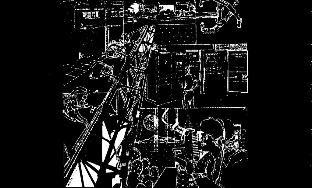

49 ANTENNA SYSTEMS


50 ANTENNA SYSTEMS, AM & FM TOWERS i Introduction Continental offers broadcasters a complete antenna system service, including manufacturing, testing, and field supervision of directional or omni -directional AM and FM antennas; AM and FM towers; antenna phasing and coupling systems and related antenna system equipment. AM & FM Towers Continental can supply a variety of self -supporting and guyed antenna towers, custom designed to meet specific AM or FM station requirements. lowers are normally supplied with a protective coating of rust inhibitive paint prior to shipment; they can be supplied with a galvanized finish. All hardware, fittings, guy insulators, anchor steel and base insulator are supplied with each tower. Appropriate tower lighting kits to meet FCC /FAA or ICAO requirements, are also available; see "Antenna System Accessories ". Towers available from Continental include: Pi Rod, Rohn, Stainless, Utility, V & B, and World. All of the construction capabilities and services of these companies are available to Continental customers. 48


51 ANTENNA PHASING & COUPLING Introduction Since its founding in 1946, Continental Electronics has designed and manufactured phasing and coupling equipment to meet the needs of broadcasters around the world. Many of the techniques used today in phaser design were pioneered, developed and refined by Continental engineers. Continental engineering and manufacturing personnel can draw upon a wide and varied experience in preparing your phasing equipment proposal: experience that includes designing, building, installing, testing and operating transmitters and related rf equipment ranging in power from 1,000 to 2,000,000 watts. Typical System A directional antenna phasing and branching system consists of: an impedance matching circuit which matches the power divider input impedance to the common point impedance at which the power input is measured a branching circuit in which power is precisely divided into the amounts of power necessary to give the proper ratio of fields from individual antennas phase shifting networks in series with each of the transmission lines going to the individual antenna towers the transmission lines the antenna coupling unit (ACU) for impedance matching between each transmission line and its associated antenna tower. Continental Phaser Design Practices Continental phasing systems offer optimal impedance and pattern bandwidths with wide adjustment range based on highly accurate, computer analysis of antenna tower impedances. All designs avoid network configurations which directly impair bandwidth, such as those which have excessive individual phase shifts or excess tower base reactance tuning. If special bandwidth compensation networks or rejection filters are used, rf losses, voltage gradient and circulating currents are carefully calculated and their impact is included in the final system design. All system components are carefully evaluated and selected on a best- performance /bestengineering practice basis. For example: vacuum capacitors and vacuum rf contractors are used when appropriate. Conservatively -rated components are used throughout the design. A static drain device is provided in the antenna coupling unit for each tower, unless this function is performed by the ground winding of an existing lighting choke, or other means. Accuracy of network calculations is enhanced by the use of digital computers. Special system analysis is used to predict or optimize adjustment interaction, sensitivity and bandwidth. Continental's ongoing antenna systems research assures all customers that they will benefit from the most current proven designs. 49


 Tower currents at the sidebands.")


52 ANTENNA PHASING & COUPLING s Continental "Wideband" Phaser Continental engineers have developed a technique that optimizes the impedance and Vattern bandwidths of a phased ârray. Following is an overview of this technology. After completion of the initial phaser design, the sideband self and mutual impedances are calculated based on electromagnetic propagation less than the speed of light. Because sideband parameters are frequently dependent, different tower electrical heights and spacings exist from those specified for the carrier frequency. Then, three network models of the towers are calculated: one at carrier, and one at each sideband. The components of each network are placed in the phaser topology, and the whole system is then analyzed by a computer program using admittance matrix algebra. Component reactances and transmission line lengths are automatically adjusted for frequency. The effects of coil Q and transmission line loss are included. The frequency -sensitive tower impedance model answers two questions which cannot be answered if the tower system's current ratios or operating impedances are assumed to be constant. They are: (1) Tower currents at the sidebands. (2) Rower currents at the carrier during the adjustment process. Obtaining the common -point impedance, VSWR and the tower currents, and the effect each component has on these parameters, enables Continental engineers to prepare an optimum system design. In addition to "widebanding ", this technique can be used to study adjustment sensitivity at carrier. It can also be used to give advance indication when a power divider control is more of a phase control and vice -versa. Adjustment interaction can be optimized during the design process. - I s II a a 41., " (..11*l.:1%.! ' sien MIMI Iiii i 50


53 4 4 rn.stl. i NIGNI - sown Typical Network Construction Practice Interconnecting bus matches associated inductor tubing, or is based on a minimum of 1/2-inch of diameter per each 10 RMS amps of current. The smallest diameter tubing used is 3/8 -inch. Where flexible connections are required, '/z -inch x 20 -mil copper strap is used per 10 RMS amps of current. The bus size will be selected to minimize or optimize voltage gradient when a dielectric- heating or ionization probability exists. All components are removeable from inside the cabinets or from the front surfaces of wall panels. All mounting screws fit in tapped holes or captive nuts, so separate nuts are not required. All hardware is non -ferrous. t SWIM MAIN Ui Di NIONI - i ANTENNA PHASING & COUPLING Iowl4 > 1OWfl 4 i Aluminum and copper parts are irridited, cadmium or silver plated, or as specified. A cabinet that is located in a transmitting room has an interlock circuit, if requested. Epoxy -cast mica capacitors are provided with flanges for additional heat -sinking, and to facilitate connection and mounting. Front panel controls consist of knobs or handles, counters and insulated, flexible couplings. Co -ax outer conductor "U" clamps are provided for transmission line termination unless other termination is specified. Photo -etched nameplates are used on all phaser cabinet front -panel meters and controls. Phaser cabinets use overhead grills to allow convection cooling. Panels which act as electrical ground are aluminum, and are - bonded to each other with two -inch wide copper straps. A rolled six foot length of two -inch wide or four -inch copper strap, depending upon power level, is provided with each cabinet for connection to the customer's ground system. The selection of stand -off insulators and insulation materials is based on strength, low dielectric dissipation factor and low moisture absorption. Tubing indicator taps are plated, solid brass to provide good electrical connection and heat sinking. Jacks are always positioned so that a plug -in ammeter will face the operator from a horizontal position. All co -ax input /output connections are located to customer specifications. If the customer has no preference, input co -ax connections will be located at the top of the phaser cabinet, output co -ax connections at the bottom. Control connections will usually be located at the bottom of all cabinets or panels. ACU inputs will usually be at the lower left; outputs at the upper right. 51


54 ANTENNA PHASING & COUPLING Typical Control Circuit Design Practices Continental's standard 28 vdc control circuit is designed for mounting in a 19 -inch rack; either directly in the front panel of the phaser, or externally. Color -coded LEDs give status indications for each tower and phaser cabinet. The momentary push- button switches must be depressed for a full second before switching will begin. This prevents accidental mode change if an operator accidentally depresses a push- button, and assures that the transmitter has adequate time to remove rf output. If desired, the full- second contact can be performed automatically with the addition of two relays. Remote control capability is built -in to the standard circuit with a "local only" switch for personnel safety during maintenance. A separate remote control panel is available as an option. Control lines can be specified as 28 vdc or 220 vac. Line voltage to the control panel can be specified as 120 vac or 240 vac; 50 or 60 Hz. A "Failsafe" circuit will prevent the transmitter from returning to the air if a mode change is incomplete. All relays are the same plug -in type. Time delay is accomplished with RC decay networks. Required Design Data Continental custom designs and manufacturers antenna phasing and coupling equipment to meet specific broadcasting station requirements. Following is the typical data Continental needs in order to prepare an equipment proposal. call letters and station location; frequency of operation; operating power (day and night); and mode of operation description of towers; tower manufacturer; type number and tower height; self - supported or guyed; and cross - section dimensions spacing and orientation of all antennas in the array phase relationship and ratios of the radiation fields location of phasing unit type and length of each transmission line. 52

.")


55 FM ANTENNAS FM Antennas Continental offers FM broadcasters a wide variety of antennas to meet commercial and educational station requirements: from low power to high power; including circularly and horizontally polarized, and dual polarized directional antenna designs. G5 Series, Circularly Polarized FM Antennas The G5 antenna was introduced in Since then, it has become the most popular FM antenna available in the United States. It is an electrically sound, mechanically rugged, thoroughly field- proven antenna design. The antenna may be purchased in any number of bays from 1 to 16 (Series A & B). Each bay level element consists of two segmented series -fed dipoles that form a space -phased, circularly polarized radiator. Each segmented dipole is manufactured using a custom made Wallace Bending machine. The dipoles are constructed of 31/2" o.d. brass which provides an excellent element bandwidth as well as protection against corona discharge failure. The isolated feed point of the two segmented dipoles is pressurized to avoid the effects of atmospheric changes and metal corrosion on the feed point impedance. The insulators are custom made melamine insulators with machined flange fittings for bolt down "O" ring sealed flange assembly. Each feed point is silver soldered to the inner conductor inside the driven element; the entire inner conductor assembly of the element is silver plated to minimize antenna loss. Each individual segmented dipole can be removed from any bay level element and replaced with a new segmented dipole with no change in the VSWR of the antenna. Each segmented dipole is constructed with a captive male 31/4" coax 50 ohm inner conductor connector, and is connected to the antenna element using a five bolt pinned flange. This unique construction design assures proper dipole installation. Electrically, each element in a G5 array is a 50 ohm element at the frequency of operation. When the array is matched, a quarter wave transformation section is designed for each element's feed stem, so that each element adds in shunt with the other elements in the array, with impedance of n x 50 ohms, where n equals the number of elements being added in shunt. This method of matching limits the maximum voltage and current in the antenna array interbay coax while utilizing the advantage of a 50 ohm bay level impedance. The G5 antenna design is very flexible: it permits side, corner leg or top mounting on any type of tower. All radiating elements and feed stem are constructed of brass; all support brackets and hardware are made of stainless steel. 53


56 G5CPS FM ANTENNA G5CPS Super Power Circularly Polarized FM Antenna The brass radiating element has an outside diameter of 3'/8 ". The feed point is completely internal with a pressurized environment up to the feed point. The radiating element is rated at 40 kw, and is limited by the safe average power capability of the 3W rigid coax line. The heavy -wall brass tubing stem can withstand harsh environmental conditions. Deicers are not recommended in normal environments because typical VSWR is 1.5:1 or less with 1" of radial ice. Heaters or radomes are available for deicing. All G5CPS antennas use silver -plated inner conductor connectors throughout to reduce losses and heating. Each antenna, supplied with a 6 foot input matching section has 50 -ohm EIA input. Depending on model type, the input is either a 31/8 inch 50 ohm EIA female input or a 61/8 inch 50 ohm EIA female input. Once each antenna is completely assembled and factory -tuned to the customer's frequency, it is pressure tested at 10 lbs. pressure for one hour to ensure that the antenna is leak -free prior to shipment. The antenna system feed point is 6 feet below the bottom bay for end fed antennas, and approximately 6 feet below the center of the antenna for center fed antenna systems. The horizontally polarized horizontal -plane radiation pattern is omnidirectional when pole - mounted atop a tower; a ± 2 db circularity is typical when mounted on a 14 inch diameter steel pole. When side -mounted on a tower, the antenna pattern will be affected by the tower structure. Complete antenna pattern measurement services are available on a quotation basis. Horizontal plane relative field patterns are measured on a full scale mock up of a 20 foot section of the customer's tower, including the ladder, coaxial transmission lines, conduits, cables and antenna element. Pattern optimization for both horizontal and vertical polarization is available for improving the pattern circularity of the antenna -support tower combination. Precision model studies are also available for situations where larger vertical aperatures of the array need to be analyzed. The G5CPS has a low standing - wave ratio of 1.07:1, or less KHz for a given channel with field trimming. The VSWR at antenna input without field trimming is 1.2:1 for pole mounting atop a tower; 1.5:1 or less when side mounted on a tower. Multistation operation is possible using a common antenna system due to the excellent bandwidth characteristics of the G5 antenna design. Continental can quote filtering components required for the diplexing or multiplexing operation. Stations with a frequency separation as large as 4 MHz can be diplexed on a common antenna. Specifications. Frequency Range: 88 to 108 MHz, factory tuned to one frequency Polarization: Circular (clockwise) Power Gain: See tables Azimuthal Pattern: ± 2 db in free space, both horizontal and vertical Ellipticity: ± 3 db in free space VSWR at input (without field tuning): 1.1:1 top mounting, 1.5:1 or better side mounting VSWR at Input (with field tuning): 1.1:1 or better (see tables for rest of specifications) 54


57 G5CPS FM ANTENNA Series A 31/2" interbay line, 31/2" element stem No. of Power DB Type Bays Gain Gain Feed End Female 50 Ohm Input 3 V Power' Input Capability 32 KW Lbs. Calculated Weight 114 Lbs. Calculated Wind Load # End 3W 32 KW ' Center 31/2' 39 KW ' Center 61/2" 64 KW ' End 3'/s" 32 KW ' End 3' /s" 32 KW ' Center 314" 39 KW ' Center 6' /8' 64 KW ' End 3' /s" 32 KW ' End 31/4" 32 KW ' Center 31/2" 39 KW ' Center 61/2' 64 KW ' End 31/2' 32 KW ' End 3Vs" 32 KW ' Center 3W 39 KW ' Center 61/2' 64 KW ' Center 31' 39 KW ' Center 61/2" 64 KW ' Center 31/2' 39 KW ' Center 61/2' 64 KW ' Series B 4'/8" interbay line, 41/2' element stem End 6' /s" 40 KW End 6' /s" 56 KW ' Center 6' /é" 80 KW ' End 61/2' 56 KW ' End 6' /s" 56 KW ' Center 61/2' 112 KW ' End 61/2' 56 KW ' End 61/2' 56 KW ' Center 61/2" 112 KW ' End 61/2" 56 KW ' End 61/2" 56 KW ' Center 61/2" 112 KW ' Center 61/2' 112 KW ' Center 61/2" 112 KW ' Series C 61/2" interbay line, 41/2' element stem End 61/2" 40 KW End 61/2" 80 KW ' End 61/2" 120 KW ' End 61/2' 120 KW ' End 61/2" 120 KW ' End 6' /s" 120 KW ' # Wind load based on 50/33 PSF. Note: Brackets included in weight and wind load calculations. Power input capability up to 2000 feet above mean sea level, derating required above 2000 feet. 137 Approx. Length - ( 55


 Power Gain: See tables Azimuthal Pattern: ± 2 db in free space, both horizontal and")
 No. of Bays Power Gain' db Gain' Type Feed2 Female 50 -Ohm Input (mm) In. Power Input Capability Calculated Weight lb.")
 3'/s 12 kw 147 (66.68) 289 (131.09) 10 (3.05) 3 1.5588 1.9278 End (41.3) 1% 9 kw 170 (77.11) 323 (146.51) 20 (6.10) 3 1.5588 1.9278 Center (79.4) 31/4 12 kw 204 (92.53) 399 (180.98) 20 (6.10) 4 2.")
 543 (246.30) 40 (12.19) 5 2.7154 4.3384 Center (79.4) 31/4 12 kw 317 (143.79) 620 (281.23) 40 (12.19) 6 3.3028 5.1888 End (41.3) 16/4 9 kw 340 (154.22) 654 (296.65) 50 (15.24) 6 3.3028 5.1888 Center (79.")
 70 (21.34) 9 5.0826 7.0608 Center (79.4) 31/2 12 kw 543 (246.30) 1060 (480.81) 80 (24.38) 10 5.6800 7.5435 Center (79.4) 31/4 12 kw 599 (271.70) 1171 (531.16) 90 (27.43) 11 6.2783 7.")
 'Power split is 50/50 vertical and horizontal only.")
58 G5CPM FM ANTENNA G5CPM Medium Power Circularly Polarized FM Antenna The G5CPM offers broadcasters the advantages and benefits of a super power antenna in a medium power size. The heavy -duty brass radiating element has an outside diameter of 13/4'. The internal feed point is pressurized up to the feed point. Inner conductors are constructed to reduce losses and heating. The radiating element is rated at 9 kw, and is limited by the safe average power capability of the 15 /8 rigid coax line. The heavy -wall brass tubing stem can withstand harsh environmental conditions, winds up to 125 mph, and moderate ice loads. Deicers are not available. Radomes are available for deicing. The typical VSWR with 1 /3" radial ice is 1.5:1 or less. Specifications: Frequency Range: 88 to 108 MHz, factory tuned to one frequency Polarization: Circular (clockwise) Power Gain: See tables Azimuthal Pattern: ± 2 db in free space, both horizontal and vertical Ellipticity: ± 3 db in free space VSWR at Input (without field tuning): 1.1:1 top mounting, 1.5:1 or better side mounting VSWR at Input (with field tuning): 1.1:1 or better (see tables for rest of specifications) No. of Bays Power Gain' db Gain' Type Feed2 Female 50 -Ohm Input (mm) In. Power Input Capability Calculated Weight lb. (kg) Calculated Windload3 lb. (kg) End (41.3) 15 /8 9 kw 57 (25.85) 102 (46.27) Approx. Length ft. (m) End (41.3) 1% 9 kw 114 (51.71) 212 (96.16) 10 (3.05) Center (79.4) 3'/s 12 kw 147 (66.68) 289 (131.09) 10 (3.05) End (41.3) 1% 9 kw 170 (77.11) 323 (146.51) 20 (6.10) Center (79.4) 31/4 12 kw 204 (92.53) 399 (180.98) 20 (6.10) End (41.3) 16 /e 9 kw 227 (102.97) 433 (196.41) 30 (9.14) Center (79.4) 31/4 12 kw 260 (117.93) 509 (230.88) 30 (9.14) End (41.3) 1% 9 kw 283 (128.37) 543 (246.30) 40 (12.19) Center (79.4) 31/4 12 kw 317 (143.79) 620 (281.23) 40 (12.19) End (41.3) 16/4 9 kw 340 (154.22) 654 (296.65) 50 (15.24) Center (79.4) 31/4 12 kw 373 (169.19) 730 (331.12) 50 (15.24) Center (79.4) 31/4 12 kw 430 (195.04) 840 (381.02) 60 (18.29) Center (79.4) 31/4 12 kw 486 (220.45) 950 (430.91) 70 (21.34) Center (79.4) 31/2 12 kw 543 (246.30) 1060 (480.81) 80 (24.38) Center (79.4) 31/4 12 kw 599 (271.70) 1171 (531.16) 90 (27.43) Center (79.4) 31/2 12 kw 656 (297.56) 1281 (581.05) 100 (30.48) Center (79.4) 31/4 12 kw 712 (322.96) 1391 (630.95) 110 (33.53) 'Power split is 50/50 vertical and horizontal only. Beam tilt and null fill, are available as extra cost options on center fed antennas, but will change the gain figures given above and may reduce the power rating. 2End feeding is done with a 6 ft (1.83m) matching transformer section. Center feeding of an odd number of bays is done at a point one -half bay below the center of the antenna. 10 ft (3.05m) matching transformer is connected to an elbow at the center feed point and extends downward. 3Windload based on 50/33 psf (244.1/161.1 kgm). Brackets are included in weight and windload calculations. 4End fed antenna lengths do not include transformer. 56


.")

, beam tilt and/or null fill are available at extra cost.")
 Power Gain: See tables Azimuthal Pattern: ± 2 db in free space, both horizontal and")
 Input Power Rating kw Approx. Length (m) ft Weight (Including Brackets) (kg) lb Wind Load Based on 244/161 kg /sq.")
 (kg) lb Power Gain db Gain Field Gain Type Horiz Vert Horiz Vert Horiz Vert G4CPH -1 0.4611 0.4611-3.3623-3.3623 0.6790 0.6790 10 (38) 84 (65) 144 (47) 104 (120) 265 G4CPH -2 0.")
 20 (124) 274 (223) 492 (152) 334 (388) 855 G4CPH -4 2.1332 2.1332 3.2903 3.2903 1.4605 1.4605 40 (9( 30 (165) 364 (302) 666 (201) 444 (522) 1150 G4CPH -5 2.7154 2.7154 4.3384 4.3384 1.")
 60 (288) 634 (538) 1187 (351) 774 (923) 2034 G4CPH -8 4.4872 4.4872 6.5197 6.5197 2.1183 2.1183 40 (21) 70 (328) 724 (617) 1361 (401) 884 (1056) 2329 G4CPH -9 5.0826 5.")
59 G4CPH FM ANTENNA G4CPH High Power Circularly Polarized FM Antenna The G4CPH is a rugged, heavy -duty design capable of handling powers from 5 kw (single bay) to 40 kw (eight or more bays). The antenna may be purchased in any number of bays from 1 to 16. The antennas are end fed in combinations from one to eight bays. In center fed antenna arrays, the center fed "T" input is located one half bay spacing below the center of the array if the array consists of an odd number of bays. Antennas of one to eight bays are end fed with a 6 foot matching section connected to the bottom bay. The rings of the antenna are mounted on 3t /á' transmission line with a 31 /s" input flange on standard antennas. Antennas that are to have 40 kw input are provided with a 6W flange and center feed block (at extra cost). 3" diameter Corona balls are provided at the outer extremity of the arms of each bay of the antenna. The antenna is designed to withstand wind velocities to 150 miles per hour. Factory- installed deicers are available in powers of 300 and 500 watts per bay. Specify 120- or 230 -volt operation when ordering. Shielded interbay heater cable and junction boxes are supplied as a part of the heater system. Heater weight, including junction boxes and cable, is 7 lb. per bay. Heaters are field replaceable. Special power splits, other than 50/50 (vertical and horizontal), beam tilt and/or null fill are available at extra cost. Radomes are also available to reduce the effect of ice on the VSWR of the antenna. Specifications: Frequency Range: 88 to 108 MHz, factory tuned to one frequency Polarization: Circular (clockwise) Power Gain: See tables Azimuthal Pattern: ± 2 db in free space, both horizontal and vertical Ellipticity: ± 3 db in free space VSWR at Input (without field tuning): 1.1:1 top mounting, 1.5:1 or better side mounting VSWR at Input (with field tuning): 1.1:1 or better (see tables for rest of specifications) Input Power Rating kw Approx. Length (m) ft Weight (Including Brackets) (kg) lb Wind Load Based on 244/161 kg /sq.m (50/33 lb /sq RI (kg) lb Weight (With Radomes Incl. Brackets) (kg) lb Wind Load With Radomes Based on 244/161 kg /sq.m 150/33 lb/sq ft) (kg) lb Power Gain db Gain Field Gain Type Horiz Vert Horiz Vert Horiz Vert G4CPH (38) 84 (65) 144 (47) 104 (120) 265 G4CPH ) 10 (83) 184 (144) 318 (102) 224 (254) 560 G4CPH (6) 20 (124) 274 (223) 492 (152) 334 (388) 855 G4CPH (9( 30 (165) 364 (302) 666 (201) 444 (522) 1150 G4CPH (12) 40 (206) 454 (381) 840 (251) 554 (655) 1445 G4CPH (15) 50 (247) 544 (460) 1014 (301( 664 (789) 1740 G4CPH (18) 60 (288) 634 (538) 1187 (351) 774 (923) 2034 G4CPH (21) 70 (328) 724 (617) 1361 (401) 884 (1056) 2329 G4CPH (24) 80 (379) 835 (729) 1608 (460) 1015 (1223) 2697 G4CPH (27) 90 (420) 925 (808) 1782 (510) 1125 (1357) 2992 G4CPH (30) 100 (460) 1015 (887) 1956 (560) 1235 (1491) 3287 G4CPH (34) 110 (501) 1105 (966) 2130 (610) 1345 (1625) 3582 G4CPH (37) 120 (542) 1195 (1045) 2303 (660) 1455 (1758) 3876 G4CPH (40) 130 (583) 1285 (1124) 2477 (710) 1565 (1892) 4171 G4CPH (43) 140 (624) 1375 (1202) 2651 (760) 1675 (2026) 4466 G4CPH (46) 150 (665) 1465 (1281) 2825 (810) 1785 (2160) 4761 All antenna brackets are stainless steel. All weights given include brackets, interbay line, and transformer section. Factory- installed deicers are available using either 300 watts or 500 watts per bay. Specify 120 or 230 volts. Heater elements are replaceable in the field. Shielded interbay heater cable and junction boxes are supplied. Heater weight, including junction boxes and interbay cable, is 6 lb (2.7 kg) additional per bay. 57


: 1.1:1 top mounting, 1.5:1 or better side mounting VSWR at Input (with field tuning): 1.")
 kg /sq.m (50/33 kg /sq ft) (With Radomes Incl. Brackets) 244/161 kg /sq.")
 30 (89) 197 (188) 415 (122) 269 (347) 764 G4CPM-5 2.7154 2.7154 4.3384 4.3384 1.6478 1.6478 12 (12) 40 (108) 238 (229) 505 (149) 328 (427) 941 G4CPM-6 3.3028 3.3028 5.1888 5.1888 1.")
 361 (352) 775 (229) 505 (668) 1473 G4CPM-9 5.0826 5.0826 7.0608 7.0608 2.2545 2.2545 12 (24) 80 (182) 402 (392) 865 (256) 564 (748) 1650 G4CPM-10 5.")
60 G4CPM FM ANTENNA G4CPM Medium Power Circularly Polarized FM Antenna The G4CPM medium power antenna is a rugged antenna but lower in weight, windloading and power handling capability than the G4CPH antenna. This antenna is built in 4 to 12 bays and is designed to handle powers up to 12 kw input. The G4CPM is designed to withstand wind velocities to 150 miles per hour. All of these antennas are center fed, if an even number of bays, or at a point one -half bay below the center of the antenna if an odd number of bays. The low dead weight and wind loading make this antenna ideally suited for mounting on lightweight tower structures. The rings of the antenna are mounted on 15/8" line but the center feed point is a 31/2" EIA, 50 ohm flange. A 10 ft. matching transformer is connected to an elbow at the center feed point and extends downward from this point. Factory- installed deicers are available in powers of 300 and 500 watts per bay. Specify 120 or 230 -volt operation when ordering. Shielded interbay heater cable and junction boxes are supplied as a part of the heater system. Heater weight, including junction boxes and cable is 7 lb per bay. Heaters are field replaceable. Special power splits, other than 50/50 (vertical and horizontal) beam tilt and null fill are available at extra cost. Radomes are also available to reduce the effect of ice on the VSWR of the antenna. Specifications: Frequency Range: 88 to 108 MHz, factory tuned to one frequency Polarization: Circular (clockwise) Power Gain: See tables Azimuthal Pattern: ± 2 db in free space, both horizontal and vertical Ellipticity: ± 3 db in free space VSWR at Input (without field tuning): 1.1:1 top mounting, 1.5:1 or better side mounting VSWR at Input (with field tuning): 1.1:1 or better (see tables for rest of specifications) Wind Load Based on Wind Load With Radomes Input Weight 244/161 Weight Based on Power Gain db Gain Field Gain Power Rating Approx. Length (Including Brackets) kg /sq.m (50/33 kg /sq ft) (With Radomes Incl. Brackets) 244/161 kg /sq.m (50/33 Ib'sq ft) Type Horiz Vert Horiz Vert Horiz Vert kw (m) ft (kg) lb (kg) lb (kg) lb (kg) lb G4CPM (10) 30 (89) 197 (188) 415 (122) 269 (347) 764 G4CPM (12) 40 (108) 238 (229) 505 (149) 328 (427) 941 G4CPM (15) 50 (127) 279 (270) 595 (176) 387 (507) 1118 G4CPM : ( (145) 320 (311) 685 (202) 446 (588) 1296 G4CPM ( (164) 361 (352) 775 (229) 505 (668) 1473 G4CPM (24) 80 (182) 402 (392) 865 (256) 564 (748) 1650 G4CPM (27) 90 (201) 443 (433) 955 (283) 623 (829) 1828 G4CPM (30) 100 ( (474) 1045 (309) 682 (909) 2005 G4CPM (34) 110 (238) 525 (515) 1135 (336) 741 (990) 2182 All antenna brackets are stainless steel. All weights given include brackets, interbay line, and transformer section. Factory- installed deicers are available using either 300 watts or 500 watts per bay. Specify 120 or 230 volts. Heater elements are replaceable in the field. Shielded interbay heater cable and junction boxes are supplied. Heater weight, including junction boxes and interbay cable, is 6 lb (2.7 kg) additional per bay. 58


61 G4CPL, FM ANTENNA G4CPL Low Power Circularly Polarized FM Antenna The general construction of the G4CPL FM Antenna is the same as the G4CPM medium power antenna except that it is only offered in one to eight bays, is end fed and has a power handling capability of 3 kw for one bay, 6 kw for two bays and 7.5 kw for antennas with three to eight bays. The rings of the antenna are mounted on 15/tí" line and are end fed. A 6 ft. matching transformer extends below the lower bay and terminates in a 15 /s" EIA, 50 -ohm flange. Factory -installed deicers are available in powers of 300 and 500 watts per bay. Specify 120 or 230 volt operation when ordering. Shielded interbay heater cable and junction boxes are supplied as a part of the heater system. Heater weight, including junction boxes and cable, is 7 lb per bay. Heaters are field replaceable. No special power splits other than 50/50, nor beam tilt nor null fill are offered for this antenna. Radomes are also available on the VSWR of the antenna. Specifications: Frequency Range: 88 to 108 MHz, factory tuned to one frequency Polarization: Circular (clockwise) Power Gain: See tables Azimuthal Pattern: ± 2 db in free space, both horizontal and vertical Ellipticity: ± 3 db in free space VSWR at Input (without field tuning): 1.1:1 top mounting, 1.5:1 or better side mounting VSWR at Input (with field tuning): 1.1:1 or better (see tables for rest of specifications) Wind Load Based on Wind Load With Radomes Input Weight 244/ 161 Weight Based on Power Gain db Gain Field Gain Power Approx. (Including kg /sq.m (With Radomes kg /sq.m Rating Length Brackets) 150/33 lb/sq ft) Incl. Brackets) 150:33 lb/sq R) Type Horiz Vert Horiz Vert Horiz Vert kw ( m ) R (kg) R (kg) ft (kg) ft (kg) ft G4CPL (16(36 (34) 74 (24) 54 (73) 161 G4CPL (3) ) 77 (47) 104 (52) 115 (153) 338 G4CPL (6) 20 (54) 118 (115) ) 172 (234) 515 G4CPL (10) 30 (72) 159 (156) 344 (105) 231 (314) 693 G4CPL (12) 40 (91) 200 (197( ) 290 (385 ( 870 G4CPL ) 50 (109) 241 (238) 524 (158) 349 (475) 1047 G4CPL (18) 60 ( (279) 614 (185) ) 1224 G4CPL (21) ) 323 (319) 704 (212) 467 ( All antenna brackets are stainless steel. All weights given include brackets, interbay line, and transformer section. Factory- installed deicers are available using either 300 watts or 500 watts per bay. Specify 120 or 230 volts. Heater elements are replaceable in the field. Shielded interbay heater cable and junction boxes are supplied. Heater weight, including junction boxes and interbay cable, is 6 lb (2.7 kg) additional per bay. 59


62 EDUCATIONAL LOW POWER FM ANTENNA Educational Low Power FM Antenna For low power educational broadcasting applications, Continental offers the economical Educational FM antennas produced by Phelps Dodge. Available in either horizontally or circularly polarized models, these antennas, because of the normally lower power required in the educational service, are fabricated of /8" stainless steel tube. The circularly polarized antenna is a 11/2 turn helix and the horizontal polarized element has a U configuration. The educatonal antennas are complete with a matching harness of RG type cables and are designed to mount on tower legs or support pipes 11/4" to 23/4" in diameter. The multi -element arrays have an element spacing of 10 feet. Circularly Polarized FM Educational Antenna Specifications Type No. Gain Net And Power In Field FS C 1 Mile Wt. Bays Gain db Gain 1 kw, µv /ml Lb Power Rating kw Wind Load 50/33 lb /ft2 ECFM ECFM ECFM ECFM ECFM ECFM Educational FM Antennas are designed to mount on tower legs or support pipes having diameters up to 7 cm (23/4 ") The spacing between bays is 3.1 m (10 ft). Education FM Antennas are led with RG -8 and RG -11 cables and all have type N Male Input Connector. Horizontally Polarized FM Educational Antenna Specifications Type No. Gain Net And Power In Field FS (a' 1 Mile Wt. Bays Gain db Gain 1 kw, µv /ml Lb Power Rating kw Wind Load 50/33 lb /ft2 EHFM EHFM EHFM EHFM EHFM EHFM Educational FM Antennas are designed to mount on tower legs or support pipes having diameters up to 7 cm (23/4") the spacing between bays is 3.1m (10 ft.) Educational FM Antennas are fed with RG -8 and RG -11 cables and all have a type N Male Input Connector. 60


, or 31/8\" EIA 50 ohm female input (type number and suffix B).")

63 G4D FM ANTENNA G4D Dual Polarized Directional FM Antenna The G4D supplied with a custom matching pole* permits support pole drop shipment directly to the customer. Several poles are available at the antenna pattern range for testing. The G4D uses broadband 31 /s" diameter dipole elements. In normal environmental conditions, the elements do not require deicing. Each bay level normally uses two driven horizontal elements, one horizontal parasitic reflector, and one driven vertical element. In some cases, vertical parasitic elements may be used on each bay to further shape the vertical polarization component. The G4D antenna, with maximum 8 -bay availability, uses a suffix after the type number to denote the number of bays. Vertical spacing between bays is one wavelength. The interbay lines use a 31 /8" rigid transmission line. Three such lines are used between bays; two for horizontal element feeds and one for vertical element feeds. A combiner for the three transmission line feeds is used below the bottom bay; a 6 foot matching section is used directly below this combiner. The G4D is available with a 15/8" (type number and suffix A), or 31/8" EIA 50 ohm female input (type number and suffix B). Maximum power input capability is 12 kw for A series; 20 kw for B series single bay; 40 kw for B series, 2 through 8 bays. Deicers are not supplied because of the good bandwideth characteristics of the array. Typical bandwidth is approximately 5 MHz between 1.5:1 VSWR points; the VSWR during minor icing conditions should not exceed 1.5:1. Four typical directional FM antenna patterns are shown in the following four figures. The final pattern achieved may differ slightly from the initial pattern proposed, so that the customer may be required to file an application to modify the construction permit to comply with the pattern achieved on Continental's antenna pattern range. % 61
, and the transmitter power output capability. Such antenna pattern requirements are normally specified by the station consultant.")

64 G4D FM ANTENNA Orders for the G4D should specify the desired true azimuth orientation, maximum ERP permitted, radiated power limitations and their true orientation, transmission line efficiency (or type of transmission line and length), and the transmitter power output capability. Such antenna pattern requirements are normally specified by the station consultant. A copy of the FCC construction permit should be provided with the order. Table 1 gives typical gain figures for each of the patterns shown. Table 2 lists the pole length for each antenna type, height of the electrical center above the support tower, weight, wind loading, etc. *The directional antenna may be purchased without the pole only on a special quotation basis; an added engineering charge will be made, and cost of the pole deducted from the total price. Note: The listed power gain figures are approximate only, but are useful Type G4D -( ) Dual Polarized Directional FM Antenna as a guide in determining the number of bays required. The gain figures will vary with the pattern shape, and the exact gain figures are determined when the final antenna pattern is achieved. The power gain for the vertical polarization component may be less than the horizontal polarization component since it will differ a bit in shape. The RMS of the vertically polarized component can not exceed the RMS of the vertically polarized component. In the case of educational channels, the vertically polarized component can not exceed the horizontally polarized component at any azimuth. Number of Bays Pattern 1 Pattern 2 Pattern 3 Pattern 4 Maximum Power Gain Horiz Vert Maximum Power Gain Horiz Vert Maximum Power Gain Horiz Vert Maximum Power Gain Horiz Vert Note: The listed power gain figures are approximate only, but are useful as a guide in determining the number of bays required. The gain figures will vary with the pattern shape, and the exact gain figures are determined when the final antenna pattern is achieved. The power gain for the vertical polarization component may be less than the horizontal polarization component since it will differ a bit in shape. The RMS of the vertically polarized.component can not exceed the RMS of the vertically polarized component. In the case of educational channels, the vertically polarized component can not exceed the horizontally polarized component at any azimuth. G4D -( ) Dual Polarized Directional FM Antennas Type PATTERN 1 Power Gain db Gain Horiz Vert Horiz Vert Input Power Rating kw Female Input Flange (cm) in Pole Length (m) ft Weight Pole and Antenna (kg) lb Total Wind Load Based on kg. /sq.m (50/33 lb /sq ft( (kg) lb Moment kg /m (Mb) Height of Electrical Center Above Top of Tower (m) ft Bolt Circle Diameter (cm) in G4D-1A (4.1) 1% (6) 20 (275) 606 (361) 796 (1327) 9595 (4.8) 16 (23) 9 G4D-1B (7.9) 3% (6) 20 (284) 626 (372) 832 (1383) )4.8) 16 (23) 9 G4D-2A (4.1) 1% (9) 30 (1016) 2240 (826) 1821 (4152) (6.4) 21 (43) 17 G4D-2B (7.9) 3% (9) 30 (1025) 2260 (842) 1856 (4231) (6.4) 21 (43) 17 G4D-3A (4.1) 1% (12) 40 (1358) 2994 (1160) 2557 (7595) (7.9) 26 (43) 17 G4D-3B (7.9) 3% (12) 40 (1367) 3014 (1176) 2593 (7700) (7.9) 26 )43) 17 G4D-4A (4.1) 1% (15) 50 )1926) 4245 (1583) 3490 ( (9.4) 31 (43) 17 G4D-4B (7.9) 3ye (15) 50 (1935) 4265 (1599) 3526 (12482) (9.4) 31 (43) 17 G4D-5A (4.1) 1% (19) 62 (2677) 5901 (2123) 4680 (21189) (11.5) 38 (43) 17 G4D-5B )7.9) 3ye (19) 62 (2685) 5921 (2139) 4716 (21354) (11.5) 38 (43) 17 G4D-6A (4.1) 1% (22) 72 (3609) 7956 (2505) 5523 (28795) (13.1) 43 (43) 17 G4D-6B (7.9) 3% (22) 72 (3618) 7976 (2522) 5559 (28985) (13.1) 43 (43) 17 G4D-7A (4.1) 1% (25) 82 )4196) 9250 (2880) 6350 (37523) (14.6) 48 (43) 17 G4D-7B (7.9) 3ye (25) 82 (4205) 9270 (2897) 6386 (37738) (14.6) 48 (43) 17 G4D-8A (4.1) 1% (28) 92 (5128) ( (47459) (16.1) 53 (43) 17 G4D-8B (7.9) 3ye (28) 92 (5137) (3278) 7227 ( (16.1) 53 (43) 17 62


65 G4D FM ANTENNA Pattern o o Pattern 2 o o Pattern 3 %VI 30 o o 30 k411/04 frifjp likftiffifrom ikawar. AiNatti is1**% i*va ' Pattern 4 wwwwrim 30 o o 30 7,111V. 4IPAet "1" (0.4 w g latirattila


66 37M RING FM ANTENNA 37M Ring FM Antenna A proven design that has been imitated but never duplicated in efficiency during the past decade, the Continental 37M Antenna still maintains its position of leadership in FM broadcasting. Its advanced design features make it an ideal antenna for stereo and multiplex operations. The aerodynamic simplicity and low weight of the 37M provide greater efficiencies and savings in new tower costs, erection time and maintenance expense. These benefits also eliminate undue oscillating and weaving of the tower and antenna. The Continental 37M Ring Antenna consists of only two basic parts; the radiating ring and the connecting inter -ring transmission line. Any number of rings, either odd or even, may be used to provide maximum flexibility in high power gain. Antenna arrays mounted on 15 /8" or 31 /e" lines are available for handling transmitter powers up to 20 kw. Antenna assemblies on a 15/8" line are rated for power inputs at the base of the antenna, up to 2.5 kw for a single ring array; 10 kw for four or more rings. Antenna assemblies on a 31/8" line are rated for power inputs up to 2.5 kw per ring at the base of the antenna, with a maximum of 20 kw for eight or more rings. The horizontal radiation pattern of the Continental 37M FM Antenna is essentially circular for both top- mounting and side -mounting arrays. The extent of deviation from a circular pattern in the side -mounted antenna is dependent on the type and size of tower on which the antenna is mounted. In cases of very large supporting structures, and in all cases where guy wires are used, expert recommendations should be requested on spacing of insulators and guy wires and mounting of the antenna. The voltage standing wave ratio of the Continental 37M Antenna can be maintained at better than 1.15:1 when field tuned because of the inherently high stability of the tuning system. The capacitor plates of the 37M are adjustable for optimum performance and equal power distribution through all rings. These advantages allow an accurate prediction of the gain from the given number of loops in the array. Adequate bandwidth virtually eliminates detuning effects caused by changes in atmospheric conditions. The bandwidth and linearity of the antenna are more than adequate for multiplexing service. The compactness and simplicity of the 37M allow maximum efficiency in ice removal. Each ring may be equipped with an internally mounted, 300 -watt or 500 -watt unit consisting of cartridge type elements extending the full circumference of the inside of the ring specify 120 or 230 volts. The simplicity of the heating arrangement makes it possible to replace the elements in the field if necessary. The absence of large masses of metal assures efficient and practical deicing of the antenna and capacitor, which are the most critical parts of the antenna when icing occurs. Because 37M FM Antennas are made to order, specify frequency, number of elements and size of transmission line when ordering. 64

 A single power amplifier and transmission line to provide power for each antenna.")


67 300C FM ANTENNA 300C Vertically Polarized FM Antenna Continental 300C vertically polarized FM antennas can significantly improve present horizontal -only coverage. FCC regulations permit simultaneous FM radiation in both horizontal and vertical planes. For example, if your station is authorized for 5 kw ERP horizontal, vertical radiation can be added up to the same power. Two methods are commonly used: (1) A single power amplifier and transmission line to provide power for each antenna. (2) Two power amplifiers fed from a common exciter- driver and two transmission lines. The antennas are fed separately. The preferred method will be dictated by your power situation. If minimum initial investment is your primary concern, the first method is preferred. If redundance is important, the second method permits either amplifier to be operated individually or both simultaneously. The recommended ratio of vertical to horizontal ERP is unity. Continental's Type 300C FM antenna can be installed on your present tower, and is compatible with your existing FM transmitter. Vertical polarization with Continental's 300C antenna can fill -in shadow areas, reduce null effects, improve fringe area reception, vastly improve car FM radio reception, maintain FM stereo quality and improve SCA operation. 65

 and rigid")


68 ANTENNA TRANSMISSION LINES iiiiilliplipir4vo4v :As111114, IS X. Andrew Rigid Andrew Air Heliax Andrew Foam Heliax A..d...W Cablewave Foam Wellflex AKA Transmission Lines Continental can supply transmission lines and accessories for use in flexible (foam or air dielectric) and rigid applications. Each production length of cable is tested for pulse reflection, high voltage, leakage, and continuity. Air dielectric cables are pressure checked before shipment to the job site, and are shipped with dry air pressure. Cable lengths are normally custom cut; fittings are attached at the factory. Standard cutting tolerance is percent; closer tolerance is available on special order. If desired, coaxial cables can be phase -stabilized to provide a repeating or "stable" phase- temperature characteristic. This stabilization is accomplished by heat -treating the cable at the factory. Continental can supply any cable item produced by Andrew, Cablewave, Phelps Dodge, or Prodlein; including Andrew 4" air dielectric Heliax line for high power FM applications, and Cablewave TypeHCC J 31/2" air Wellflex cable. Following are some of the most commonly used items. Flexible line, foam dielectric: 3/8", 1/2 ", 7/8", 15/8" Flexible line, air dielectric: 7/8', 15/8', 3 ", 31/2 4 ", 5 Rigid line, 50 ohm: 15/8 ", 31/2", 6" Jacks, plugs, flanges, barriers, splices, terminals, reducers. Hangers and accessories. Pressurizing equipment, coaxial switches. Cablewave Air Wellflex Cablewave Rigid 66


69 ANTENNA TRANSMISSION LINES Typical Installations ANTENNA INPUT Flexible Line EIA CONNECTOR HANGER & TOWER ADAPTOR Rigid Line HANGER & TOWER ADAPTOR 90 0 ELBOW ANTENNA INPUT STRAIGHT SECTION GROUNDING KIT 900 ELBOW TO TRANSMITTER HANGER & EIA GAS CEILING BARRIER ADAPTOR CONNECTOR WALL /ROOF FEED THROUGH HANGER & TOWER ADAPTOR RIGID HANGER & ANGLE ADAPTER STRAIGHT SECTION SPRING HANGER & ANGLE ADAPTOR TO TRANSMITTER HORIZONTAL HANGER LATERAL BRACE gui-)..,7-\3_ s t- ',, u STRAIGHT STRAIGHT GAS BARRIER SECTION SECTION HORIZONTAL ANCHOR STRAIGHT SECTION 900 ELBOW 67

 thick. Strap width Pounds per unit length 2\" (5.08 cm) 4.02 ft per lb (2.70 M /kg) 3\" (7.")
 Beacon Light Control Fisher -Pierce 63305 -DB beacon light control mounts in a standard commercial")


70 ANTENNA SYSTEM ACCESSORIES Copper Ground Wire Bare #10 AWG copper ground wire is used for ground radials. Wire attaches to mesh ground screen. Pounds per foot: lb (13 kg) per 1000 ft Copper Ground Strap Copper ground strap is available in four widths; each width is 0.032" (0.086 cm) thick. Strap width Pounds per unit length 2" (5.08 cm) 4.02 ft per lb (2.70 M /kg) 3" (7.6 cm) 3.01 ft per lb (2.02 M /kg) 4" (10.1 cm) 2.01 ft per lb (1.35 M /kg) 6" (15.2 cm) 1.34 ft per lb (0.90 M /kg) Beacon Light Control Fisher -Pierce DB beacon light control mounts in a standard commercial meter socket. It automatically controls broadcast tower lights directly, or with auxilliary contractors. An adjustable potentiometer allows adjustment for operation from 0 to 50 footcandles. Power requirements: 105 to 130 volts: 50/60 Hz Built -in load contractor: Single - pole, single throw, double break; 30 amps Load rating: 3000 watts Ice Warning System The Rosemount ice warning system consists of a controller and an ice detector *. Most ice warning and heater control systems are operated by a thermostat device; thus, antenna heaters are energized whenever the temperature drops below approximately 35 F. (1.7 C). Statistically, the probability of icing seldom exceeds 3 percent, even during the winter months. The remaining 97 percent of the time, antenna heater power activated by a thermostatic device provides expensive and unnecessary insurance against icing. The Rosemount system is designed to reduce antenna deicing costs and to fully automate antenna deicing systems. The Rosemount system will detect ice and energize antenna heaters only when ice is physically present, but before ice accumulation can reduce antenna performance. The Rosemount system thus provides reliable, completely automated antenna icing protection at a fraction of the cost for continuous heater operation whenever thè ambient temperature is below approximately 35 F (1.7 C). In many cases, the Rosemount system will pay for itself in less than one icing season. Sampling Loop The 601 series fixed phase sampling loops manufactured by Electronic Reasearch, Inc., sample the phase relationship of rf energy in the 550 to 1600 khz range. The sensitivity is adjustable by varying the fixed position of the shorting bar provided. The loops are constructed of heavy stainless steel and terminate in a Type N female plug. Two sizes are available: 48" x 12 "; 91" x
 female swivel output Type 403A: 31/8\" (7.9 cm) male swivel input; 31/8\" (7.")
 depending on frequency. Diameter: 10\" (25.4 cm) maximum.")
 line pressure maximum pass through.")


 male input; 31/2\" (7.")
71 ANTENNA SYSTEM ACCESSORIES Connectors: Type 403: 15/8" (2.86 cm) male swivel input; 1%" (2.86 cm) female swivel output Type 403A: 31/8" (7.9 cm) male swivel input; 31/8" (7.9 cm) female swivel output Weight: Approx. 105 lb (47.6 kg) including cradle. Length: 67" to 73" (170 to 185 cm) depending on frequency. Diameter: 10" (25.4 cm) maximum. Mounting: Cradle supplied with 2" (5 cm) pipe flange on bottom. Pipe stand not supplied. Pressurization: 10 lb (4.5 kg) line pressure maximum pass through. AM /FM Isolation Transformers Isolation transformers are designed to couple the FM power across the base insulator of a transmitting tower used jointly as an AM and FM radiator without introducing a mismatch into the FM feedline. An isolation transformer is especially desirable for feeding high impedance AM directional antenna system which might be adversely affected by a "bazooka" type isolation system. Each unit is factory tuned to station FM frequency. Specifications: Type A Isolation Transformers Frequency: 88 to 108 MHz VSWR: Less than 1.05:1 at the station frequency. Bandwidth: Over 2 MHz between 1.1:1 VSWR points, 50 ohm load FM power: 10 kw, 50 -ohm line. AM peak voltage: 7500 volts. AM shunt capacity to ground: Approximately 200 pf Lightning protection: Quarter -wave shorted stubs on input and output. Specifications: Type 425, 426, 427 Isolation Units Frequency: 88 to 108 MHz VSWR: Less than 1:05:1 at the station frequency. Bandwidth: Over 2 MHz between 1.1:1 VSWR points, 50 ohm load FM power: Type 425: 25 kw, 50 ohm line. Type 426: 40 kw, 50 ohm line Type 427: 50 kw, 50 ohm line AM peak voltage: 40,000 volts. AM shunt capacity to ground: Approximately 60 to 70 pf Lightning protection: Heavy -duty dc shorts between inner and outer conductors on input and output Connectors: Type 425: 31/2" (7.9 cm) male input; 31/2" (7.9 cm) female output Type 426: 31/8" (7.9 cm) male input; 31/8" (7.9 cm) female output Type 427: 61/8" (15.6 cm) male input; 61/8" (15.6 cm) female output Weight: Type 425: 256 lb (116 kg) Type 426: 300 lb (136 kg) Type 427: 325 lb ( kg) Length: Type 425: 44" (111 cm) Type 426: 44" (111 cm) Type 427: 51" ( cm) Diameter: Type 425: 281/2" (72 cm) Type 426: 281/2" (72 cm) Type 427: 281/2" (72 cm) Mounting: Cradle supplied with 3" (7.6 cm) pipe flange on bottom. Pipe stand not supplied. Pressurization: 10 lb (4.5 kg) line pressure maximum pass through. * 69


 L, 10\" (25.4 cm) D Weight: 6 lb (2.")
 in diameter and 5.5 in. (13.")
 diameter, 51/2 in. (13.9 cm) high, 101/2 in. (26.6 cm) stud.")
 diameter, 51/2 in. (13.")
72 ANTENNA SYSTEM ACCESSORIES Isolation Coil The coil provides isolation for the phase sampling loop line in AM directional antenna arrays. This coil presents a high impedance for the line across the base insulator of the tower, and consists of a phenolic coil form wound with approximately 37 turns of RG8/U or similar solid dielectric coaxial cable. The inductance of the coil is approximately 180 microhenrys. Size: 18" (46 cm) L, 10" (25.4 cm) D Weight: 6 lb (2.7 kg) Feedthru Bowl Insulator Designed to carry rf transmission line through a wall, assembly includes a bowl or bowls 7 in. (17.8 cm) in diameter and 5.5 in. (13.9 cm) high with stud length as described below: #153 Bowl Insulator; single with fittings, 7 in. (17.8 cm) diameter, 51/2 in. (13.9 cm) high, 101/2 in. (26.6 cm) stud. #154 Bowl Insulator; single with fittings, 7 in. (17.8 cm) diameter, 51/2 in. (13.9 cm) high, 101/2 in. (26.6 cm) stud. #155 Double Bowl Insulator with fittings; bowls are each 7 in. (17.8 cm) diameter, 51/2 in. (13.9 cm) high, 18 in. (45.7 cm) stud. #156 Double Bowl Insulator with fittings; bowls are each 7 in. (17.8 cm) diameter, 51/2 in. (13.9 cm) high, 18 in. (45.7 cm) hollow stud. 70


73 AUDIO EQUIPMENT

 plus two mixers with one direct and six indirect inputs per")


74 CONSOLES Continental Mark 8 8- Channel Audio Console "Value" best describes the Mark 8. This highly versatile console is not only priced competitively, but is also superbly engineered to guarantee maximum on -air time and minimum maintenance. And its features are imposing. It accepts 26 input pairs. It contains six independent mixers (with two independent inputs each) plus two mixers with one direct and six indirect inputs per mixer. It incorporates solid- state, noise - free switching circuitry; long -life, step -type ladder attenuators; and state -of -the -art switches, PC boards, and amplifiers. And there's more: from lighted VU displays to an externally- mounted power supply to separate amplifiers for monitors, headphones and cue speaker. Muting is instantaneous for both monitor and cue. The Mark 8 is built to give quick access to all gain adjustments, with easy access for fuse, lamp or module replacements. Its silk- screened back panel shows console wiring schematics, including the location and numbering of all terminal strips. An important option is an externally mounted machine control interface: it provides single button control (start /stop) for all peripheral equipment such as carts, decks and turntables. The Mark 8 is a stereo console it can be adapted for monaural operation. 72


 Frequency Response: ± 1.")
h 34\" (863.")
w 6.72\" (170.69 mm)d Weight: 15 lb (6.")
75 CONSOLES Specifications Mark 8 8 Channel Studio Console Inputs Impedance Microphones: Nominal 150 ohms Medium Level: Nominal ohms Level Microphones: - 50 dbm nominal Medium Level: -10 dbm nominal Number of Inputs: 26 medium level Any two inputs may be strapped for microphones Outputs Program Level: ± 18 dbm nominal -* 30 dbm maximum Impedance: 600 ohms Mono Mix Output: 8 dbm ohms (212P -2 Only) Monitor Level: 25 watts rms into 8 -ohm load Impedance 1btal load must no be less than 8 ohms Headphone Level: 5 watts rms into 8 -ohm load Impedance: 4 ohms minimum Noise: -125 dbm in 20 -khz bandwidth Distortion: Less than 0.5% harmonic Less than IM (60 Hz and 700 Hz: 4:1) Frequency Response: ± 1.0 db 30 Hz to 15 khz General Power Source: 120/240 volts 50/60 Hz ac Size: Weight: Power supply Size: 9" (228.6 mm)h 34" (863.6 mm)w 181/4" ( mm)d 65 lb (29.25 kg) 10" (254 mm)h 4.56" ( mm)w 6.72" ( mm)d Weight: 15 lb (6.75 kg) Machine control (optional) Size: Weight: 2.81" (71.37 mm)h 8.82" ( mm)w 15.65" ( mm)d 2 lb (0.90 kg) val 73
. It can assign any of these inputs to one of two \"programs\" (for on- the -air or for taping, for example).")
 and multi - colored LED's to Fresnel lenses and true rotary")
.")


 or latching (turntables) action.")
76 CONSOLES Continental Rock Channel Audio Console The Rock 10 is an exceptionally engineered audio mixer: It can handle inputs from a total of 30 stereo or monaural sources (microphones, turntables, carts, casettes, reel -to -reel decks). It can assign any of these inputs to one of two "programs" (for on- the -air or for taping, for example). And it processes these signals with virtually no distortion and an astounding transparent quality. In the Rock 10 you'll find the best of old and new - from push- button actuated, solid -state audio switches (eliminating pops and clicks) and multi - colored LED's to Fresnel lenses and true rotary -step attenuators. It's an amazing package, the Rock 10. And it's packed with sensible, sophisticated features, such as: Individual stereo meters for stereo channels Program 1 and Program 2 (internally -lit, with quick - to -spot numbers). Individually gain -controlled modular amplifiers for program, monitor, headphone and cue - each with complete R.F.I. shielding and separate fusing to protect solid -state components. Gold- plated contacts assure positive, noise -free connections. The remarkable quietness of the Rock 10 is also due to its separate external power supply which keeps transformer hum away from audio circuits. There are provisions for muting, warning lights, and even auxiliary input and output. Options to the Rock 10 include: Machine control interface (MCI) gives Rock 10 ability to handle start /stop operation of turntables, cart decks, reel to reel machines. The MCI can control up to 12 internally programmed functions to provide either momentary (cart decks) or latching (turntables) action. Internal plug -in jumpers are arranged for normally -open or normally -closed contact operation. The MCI is programmed by hand wiring at installation, but can be reprogrammed for future operation changes. A digital timer with large, legible numbers, is located in the center of the console. Count -up timer can be strapped to automatically reset each time a new channel is selected. The timer can be started and stopped by an external machine; it can be used in production work as a cumulative timer for recording multiple cuts on a single tape; it has front panel switches for manual resetting and selecting internal or external modes. Additional microphone pre -amplifiers. Audition circuit for recording news or network feeds or adjusting inputs in advance of airing. Mono mix -down (providing automatic AM feed when simulcasting in stereo). 74


 Noise: 75 db below")

 Power: Monitor 25 watts into")


77 Specifications CONSOLES Rock Channel Studio Console Console Program: Inputs: 30 stereo Mixers: 10 stereo Input: 0 dbm 600 ohms balanced (30 stereo) Microphone Preamplifiers - 50 dbm 150 ohms balanced Outputs: + 18 dbm 600 ohms balanced Response: 0.5 db 50-15,000 Hz Distortion: 0.25% THD 50-15,000 Hz 0.25% IMD (4:1 SMPTE) Noise: 75 db below + 18 dbm high level -125 db Equivalent Input Noise Microphone Headphone and Monitor Amplifiers (stereo, per channel) Power: Monitor 25 watts into 8 ohms Headphone 5 watt headphone Response: 1.0 db 50-15,000 Hz Distortion: 0.25% THD 0.25% IMD (SMPTE) Size: 10" (254 mm)h 46" ( mm)w 20" (508 mm)d Weight: 110 lbs (49.9 kg) including power supply B 75


 Power - switchable 30 Vdc on all microphone inputs to power condenser microphones.")


78 CONSOLES 1M Professional Microphone Mixer The M267 and M268 offer excellent performance and versatility that make them ideal choices as compact mixers for studio, remote, or original sound reinforcement use and as studio quality "add -on" mixers for expanding existing facilities. In designing these new mixers, Shure retained all the features that made the M67 and M68 the world standards -such as the wide frequency response, low RFI and line noise susceptibility, and balanced inputs and outputs. In addition to the many new features listed below, the M267 and M268 offer dramatic reduction of distortion and noise characteristics with substantial increases in gain and dynamic range. Low Distortion Tone Oscillator - 1 khz signal with front panel switch. Gold contacts! Active Gain Controls - lower noise, greater dynamic range, and automatic input attenuation through the use of feedback -type volume controls. LED Peak Indicator- faster than any VU meter, it warns user when program levels approach overload or indicates the onset of limiting. Battery Check Function- check battery condition without interrupting the program. Headphone Level Control - adjusts monitor volume to user's need. More Headphone Power - improves headphone monitoring under noisy conditions; use headphone output to drive a tape deck or power amplifier. Mic /Line Switch - XLR output and all four XLR inputs are switchable to Microphone or Line Level. Gold contacts! Simplex (Phantom) Power - switchable 30 Vdc on all microphone inputs to power condenser microphones. Headphone Ampl /Line Switch - choose Amplifier position for high level monitoring or Line position for talkback. Gold contacts! Low Distortion - less than 0.35% at line level output. Electronic Power Supply Regulation - improved performance on low or high ac line voltage. Automatic Muting Circuit - prevents annoying clicks and thumps when unit is turned on or off. Peak Program Limiter - eliminates overload distortion by monitoring program levels AND power supply level. Built -In Battery Pack - operates on three readily available 9 -volt alkaline batteries and switches automatically to battery power if ac fails. The new Shure M267 compact professional microphone mixer does it all, and, with the addition of two brackets, it will fit into an M67 rack panel! Specifications M267 Frequency Response: ± 2 db from 30 to 20,000 Hz Gain: Outputs terminated; line 600 ohms, microphone 150 ohms, mix bus 3.3K., headphone 200 ohms, tip -sleeve, ring -sleeve. Input v Output Line Microphone Mix bus Low - impedance microphone 92 db 42 db 25 db Line 40 db 10 db 27 db Mix bus 56 db 6 db - Noise: Equivalent input noise: dbv Equivalent input hum and noise: 127 dbv Distortion: Under 0.35% THD from 30 to 20,000 Hz at + 15 dbm output; under 0.5% IM distortion up to + 15 dbm output level Input Clipping Level: Microphone: 32 dbv to 5 dbv (depending on input control setting) Line: +20 dbv Mix bus: 38 dbv Output Clipping Level: Microphone: 32 dbv Line: + 18 dbm Limiter: Threshold: + 15 dbm (line output level; adapts automatically to power supply variations) Attack Time: 3 msec typical Recovery Time: 500 msec typical Peak Indicator: Lights 6 db below clipping or at onset of limiter action Operating Voltage: M267: volts, 50/60 Hz M267E: volts, 50/60 Hz (can be rewired for volts) Certifications: M267: UL Listed and CSA listed as Certified Dimensions: 75.3 mm H x 309 mm W x 227 mm D (23132 X X 9 in.) Net Weight: 2.3 kg (5 lb, 2 oz) 76 4


79 CONSOLES Micro-Trak Model 6618 Audio Console Eighteen stereo /mono inputs; 6 mixing channels; push- button, color - coded switching; individual LED indicators for each line switch - these features only begin to document why the 6618 is an ideal production console. Micro -trak's top -of -the -line has been designed with voltage - controlled preamplifiers and with main pots controlling a DV voltage which - through preamplifier VCA -sets output levels. Also included are individual potentiometers which give long life and low noise. Because of its reliable latching logic, the 6618 makes possible silent, instant push- button control of each input to the mixing bus. As you would expect, the 6618 has excellent amplifiers (10 watt per channel stereo, 2 watt headphones, cue, and an additional line level monitor for secondary studio or lobby monitor purposes). Two complete muting systems permit speakers in primary or secondary studios to be silenced. Program outputs for both stereo and mono broadcast are provided in a balanced transformer configuration at + 8dbm nominal line levels. 6618's are normally equipped with one microphone and five 20dbm high level input cards. Additional mic, high level, or turntable pre -amps are available as options. Rugged steel is the 6618's primary metal. Its cabinet is hinged for easy service - with accessible PC boards, switches, and controls that can be conveniently removed or replaced. Six Mixing channels: Input preamplifiers may be selected to be phono, high level, microphone Cueing: Available on all six mixing channels. Built -in cue speaker, 8 ohm cue available on monitor output channels with front panel switch. Input sensitivity: Microphone: 1 my rms for normal output; adjustable High level: standard 20 dbm for nominal output Frequency response: Microphone & high level: ± 1 db, 30 Hz to 20 khz at 0 dbm output Phono: RIAA ± 1dB Harmonic distortion: Less than 0.5% at nominal output Noise & hum: 60 db or better Muting: Controlled by any, all or no channels selected with internal switches. Two muting relays control cue, main monitor and secondary monitor output and provide "on air" control. Independent control of main monitor, cue, "on air" and secondary monitor and "on air ". Termination: Inputs and outputs terminated with barrier screw terminals. Size: 93/4' (24.7 cm)h 20'/4" (51.4 cm)w 16" (40.6 cm)d Weight: 34 lb (15.5 kg)
 can be fed to either model. Additional mic's can be connected with simple plug -in pre -amps.")
.")

 clipping level above + 22 dbm Monitor: 3@ 12 watts total Cue: 1 @ 1 watt with 5\" internal speaker")
80 CONSOLES LPB Signature II LPB's Model S -12 and S -14A are five channel consoles (stereo or mono) with features normally found in much larger units. 14 transformer - coupled audio inputs (2 mic, 12 line) can be fed to either model. Additional mic's can be connected with simple plug -in pre -amps. Muting monitors is a snap; the cue system is easy to operate (including level control and a 5 inch speaker); and the internal monitor amplifier is switch - selectable to monitor either "program" or two external monitor inputs. Both the stereo and mono consoles place output master level controls within convenient reach (the same holds true for program, headphone, and cue gain controls). LED peak level indicators - located in the VU meters- are standard; they may be adjusted to fire at various thresholds. These units from LPB have cabinets of 0.125" aluminum, with textured, scratch- resistant exteriors and gold anodized interiors. Specifications Mixers: Total: 5 Mono With Cue: 5 Type: Step Attenuator Inputs: Standard Factory Equipped: Mic.: 2 Hi Level: 12 Optional Maximum: Mic.: 4 Hi- Level: 14 Total: 14 Input Impedance: Mic.: 150 ohms source, Vans. Bal. Hi- Level: 600 ohms, Trans. Bal. Input Levels Mic.: selectable: -45 dbm, -55 dbm, -65 dbm Hi- Level: 10 dbm Outputs: Program: ( +8 dbm = 0 VU) clipping level above + 22 dbm Monitor: 3@ 12 watts total Cue: 1 watt with 5" internal speaker Headphones: 1, switchable between Program or Cue Outputlmpedance: Program: 600 ohms, Trans. Bal. Monitor: 2 to 8 ohms Headphones: 200 ohms and up Frequency Response: Program: ± 1.0 db 20 Hz + 20kHz Monitor: ± 1.5 db 20 Hz + 15kHz Power Requirements: Voltage: 117 Vac (234 Vac available) Frequency: 50/60 Hz Power: 60 watts Size: 9" (228.6 mm)h 103/4" ( mm)w 15" (381 mm)d Weight: 29 lb (13.05 kg) 78


81 CONSOLES Broadcast Audio Corp. System 12 is an expandable, completely modular broadcast mixer, with unprecedented features and performance. It was designed exclusively for broadcast and is not a scaled down version of recording or sound reinforcement equipment, so it performs flawlessly even in high RF environments. An elegant low profile appearance is accented by solid walnut end panels and armrest. This mixer sits on top of the desk and does not require recessed mounting, so it's easy to install, with all connections made from the top. SYSTEM 12 is a model of engineering simplicity, using motherboard construction, with only 2 types of amplifier modules and a plug -in interconnecting harness. Two independent industrial grade power supplies are rack mounted in a common housing, with front panel AC and DC status indicators. The power supply is short circuit proof and an optional redundant supply is also available. Operator conveniences include 4 inch log taper slide faders for extremely accurate tracking between channels. In addition to a cue detent position on the fader, there is a separate button for cueing when the fader is up. The stereo cue amplifier is an industry first! The panel layout is easily understood and a pleasure to operate. SYSTEM 12 features DC audio switching, using LCR's for completely quiet audio control. This also enables each mixing channel to be turned off and on from a remote location, such as an announce studio or news booth. Zen plug -in relays, with switch selection of maintained or momentary contacts, can be used for muting or remote start from any combination of mixers. Specifications Mixers: 8 standard, 12 maximum (log taper slider). Inputs: 24 standard, 36 maximum (3 per mixer). Input Impedance: 150 Ohms mic, 600 ohms line. Transformer balanced, switch selected. Input Levels: - 55 dbm mic, 0 dbm line (sensitivity adjustable 10 db). Outputs: 3 balanced stereo line, 1 balanced mono line, plus stereo cue, phone and monitor outputs. Output Levels: Line Outputs 8 dbm into 600 ohms for 0 VU indication, 24 dbm maximum output. Phones 1 watt into 4 ohms. Cue 5 watts into 8 ohm external speakers. Monitor 0.5 volts into 10K load. Frequency Response: Within 1 db, 20-20,000 Hz, mic input to line output. Harmonic Distortion: Line Outputs less than 0.15% THD 20-20,000 Hz (typically less than 0.05% at 1KHz). IM Distortion: Line Outputs less than 0.05% SMPTE. Noise: 70 db below + 8 dbm output, referenced to - 55 dbm input, 20-20,000 Hz unweighted. Equivalent input noise -125 dbm. Power: 117 volts, 5/60 Hz (230 volts optional). Size: 35W x 8.75H x 25D (inches). Shipping Weight: 110 pounds. 79


.")
.")
82 CONSOLES Broadcast Audio Corp. System 16 is an expandable, completely modular broadcast mixer, with unprecedented features and performance. It was designed exclusively for broadcast and is not a scaled down version of recording or sound reinforcement equipment, so it performs flawlessly even in high RF environments. An elegant low profile appearance is accented by solid walnut end panels and armrest. This mixer sits on top of the desk and does not require recessed mounting, so it's easy to install, with all connections made from the top. SYSTEM 16 is a model of engineering simplicity, using motherboard construction, with only 2 types of amplifier modules and plug -in interconnecting harness. Two independent industrial grade power supplies are rack mounted in a common housing, with front panel AC and DC status indicators. The power supply is short circuit proof and an optional redundant supply is also available. Operator conveniences include 4 inch log taper slide faders for extremely accurate tracking between channels. In addition to a cue detent position on the fader, there is a separate button for cueing when the fader is up. The stereo cue amplifier is an industry first! The panel layout is easily understood and a pleasure to operate. SYSTEM 16 features DC audio switching, using LCR's for completely quiet audio control. This also enables each mixing channel to be turned off and on from a remote location, such as an announce studio or news booth. Ten plug -in relays, with switch selection of maintained or momentary contacts, can be used for muting or remote start from any combination of mixers. Specifications Mixers: 8 standard, 16 maximum (log taper slider). Inputs: 24 standard, 48 maximum (3 per mixer). Input Impedance: 150 Ohms mic, 600 ohms line. Transformer balanced, switch selected. Input Levels: - 55 dbm mic, 0 dbm line (sensitivity adjustable 10 db). Outputs: 3 balanced stereo line, 1 balanced mono line, plus stereo cue, phone and monitor outputs. Output Levels: Line Outputs 8 dbm into 600 ohms for 0 VU indication, 24 dbm maximum output. Phones 1 watt into 4 ohms. Cue 5 watts into 8 ohm external speakers. Monitor 0.5 volts into 10K load. Frequency Response: Within 1 db, 20-20,000 Hz, mic input to line output. Harmonic Distortion: Line Outputs less than 0.15% THD 20-20,000 Hz (typically less than 0.05% at 1KHz). IM Distortion: Line Outputs less than 0.05% SMPTE. Noise: 70 db below + 8 dbm output, referenced to - 55 dbm input, 20-20,000 Hz unweighted. Equivalent input noise -125 dbm. Power: 117 volts, 50/60 Hz (230 volts optional). Size: 44W x 8.75H x 25D (inches). Shipping Weight: 120 pounds (2 containers). 80


 controls the studio monitor,")


 and you have an excellent console for both studio and remote broadcasts.")

 *Sensitivity: - 10dBm Max Input: + 18dBm Impedance: 600 ohms")
 Impedance: 8 ohms Total Harmonic Distortion: Less")

83 CONSOLES Russco Studio Master 505 Audio Mixer Russco's five channel mono mixer can be rack -mounted or can stand alone as an attractive table unit. Channels 1-4 each have preamps for mike or phone inputs, while any of five balanced, high level signals can be fed to channel five. Each channel has its own cue; the cue itself drives a 3" built -in speaker. Operation of the 505 is unusually easy, in part because of the pushbutton on -air switching with LED indicator lights and Allen- Bradley Mod pots which provide quiet, trouble -free performance. The built - in 25 watt amplifier (employing FET muting) controls the studio monitor, while the headphone amp accepts a stereo jack and permits either high or low impedence headphones to be used. Russco has engineered the 505 for easy maintenance: it's quickly disassembled, and all modifiable components can be conveniently reached. Match these sensible features with the 505's lightweight (14 lbs.) and you have an excellent console for both studio and remote broadcasts. Specifications Inputs: 91btal Channels 1-4 (Pre-amps) (Unbalanced) Hi Level Sensitivity* - 13dBm Max Input + 14dBm Impedance 47K Microphone ** Sensitivity* 0.8mv Max Input 13mv Impedance 47K Phono * ** Sensitivity* 7mv Max Input 100mv Impedance 47K Channel 5 (Balanced) *Sensitivity: - 10dBm Max Input: + 18dBm Impedance: 600 ohms Outputs: Monitor: Power: 25 watts average (14.4 volts RMS across 8 ohm load at 1KHz) Impedance: 8 ohms Total Harmonic Distortion: Less than 1% at full rated output. Program: Level: + 4 or + 8dBm, for OVAu, + 17dBm maximum Impedance: 600 ohms Frequency Response: 20 to 15 KHz, 1dB Total Harmonic Distortion: Less than 0.5% at 1KHz, +8dBm out. P.C. Interconnections: 16 pid DIP plugs and flat cable. Power Requirements: 117 VAC, 60Hz, 100 watts *Allen-Bradley MOD POT, Hot - molded element, rated at 100,000 rotations * *Grayhill series 46, rated at 250,000 operations. Size, rack- 51/4' ( mm)h mount 19" (482.6 mm)w model: 8" (203.2 mm)d Weight: 14 lb (6.3 kg) Size, desk- 51/4' ( mm)h mount 201/4" ( mm)w model: 8" (203.2 mm)d Weight: 14 lb (6.3 kg) 81


.")
. Cue Master Speed: 33,45,78 Platter Weight: 5.5 lb (2.5 kg) Acceleration: lhs rev.")
 below chassis Unit Weight: 16 lb (7.3 kg) Studio Pro Speed: 33,45 Platter Weight: 6.")
h 15%\" (39.")


84 TURNTABLES $ Russco Cue -Master and Studio -Pro RUSSCO is so confident about these turntables that they guarantee them for life. And well they should, because of outstanding features such as: Heavy duty Bodine synchronous motors (also available for 50 cycle operation). A drive system with a neoprone idler wheel which transmits power directly from the stepped capstan on the motor shaft to the inside platter rim. Fast acceleration (1 /16 of a revolution at 33 rpm, Vio at 45). Solid cast aluminum chassis, oilite bronze bearing, Lord shock mounts. The Studio -Pro has both 33 and 45 rpm (Cue- Master adds 78) and is the heavier of the models (20 lbs total vs. 16 lbs, with a 61 /2lbs. platter vs 51/2 lbs.) Because of this added heft, the Studio -Pro has superb wow and flutter specs (less than 3/4o of 1% vs. less than 3ho of 1% for the Cue Master). Both far exceed NAB standards for rumble (minus 38 db down and minus 36 db for the Studio -Pro and Cue - Master, respectively). Cue Master Speed: 33,45,78 Platter Weight: 5.5 lb (2.5 kg) Acceleration: lhs rev. at 33 rpm Wow and Flutter: Less than 0.3% Rumble: 36 db below NAB level Size: 151 /2" (39.4 cm)h 151/2" (39.4 cm)w 61/2" (16.5 cm) below chassis Unit Weight: 16 lb (7.3 kg) Studio Pro Speed: 33,45 Platter Weight: 6.5 lb (3 kg) Acceleration: V16 rev at 33 rpm Wow and Flutter: Less than 0.3% Rumble: 38 db below NAB level Size: 151/2" (39.4 cm)h 15%" (39.4 cm)w 71/2" (13 cm) below chassis Unit Weight: 20 lb (9 kg) Technics SP-15 Quartz Synthesizer Controlled Direct Drive Turntable Excellent performance combined with the accuracy of quartz, makes the SP-15 an outstanding value. ultra -stable rotation very low rumble virtually perfect speed reaches 331 /2 rpm from standstill in 0.4 second quartz synthesizer pitch control which allows increases /decreases in speed in 0.1% increments within a range of ± 9.9% The SP-15 is acoustically dead and highly immune to feedback. The power supply is a switching or "pulsed" type supply, operating with a 20 khz signal in place of the normal 60 Hz ac line frequency: thus avoiding potential hum -induction problems. A mechanical /electrical braking system brings the platter to a dead stop in 0.4 second; gently holds platter until play is resumed. The platter can be stopped by hand and held indefinitely without fear of damage to the turntable. Selected speed (331/2, 45 or 78.26) is digitally displayed along with any percentage of speed change selected. Type: Quartz synthesizer direct drive Motor: Ultra -low- noise, brushless, heteropole DC motor. Thrntable platter: Aluminum diecast, Diameter; 1311/32 ", Weight; 5.9 lb. (including rubber matting), Moment of inertia; 130 lb in2 Thrntable speed: 331/2, 45 and rpm Speed adjustment range: ± 9.9% in 0.1% steps Starting torque: 2.61 lb in Start -up time: 0.4 sec. to 331/2 rpm Braking time: 0.4 sec. from 331/2 rpm to standstill Speed fluctuation due to load torque: 0% within 2.2 lb in (up to 500 g tracking force) Wow & flutter: 0.025% WRMS (JIS C5521), ± 0.035% peak (IEC 98A weighted) Rumble: -56 db DIN A (IEC 98A unweighted), - 78 db DIN B (IEC 98A weighted) Size: Weight: 321/22" (92.87 mm)h 133/4" ( mm)w 1441/24" ( mm)d 13.7 lb (6.17 kg) TECHNICS SP-25 Quartz Synthesizer Controlled Direct Drive Turntable Technics quality in a basic turntable without frilss makes the SP-25 very cost -effective. Quartz- controlled servo system. Platter speed adjustment up or 8 1

 Turntable speed: 331/2 and 45 rpm Starting torque: 1.3 lb in Start-up time: 0.7 sec.")
 Rumble: 56 db DIN A (IEC 98A unweighted), 78 db DIN B (IEC 98A weighted) Size: Weight: 35/32\" (80.17 mm)h 133/4' (349.25 mm)w 1441/24\" (371.87 mm)d 10.")
 MICRO-TRAK 303-306 1Yacking is central to tone arm evaluation -and the Micro -trak Models 303 and 306 excel here: With 1/10th of a gram capabilities and resonance below 10 hz,")


 fine adjustment graduated from 0 to 2.")


85 TURNTABLE PICK -UP ARMS down within ± 6% of rated speed. Reaches 331/2 rpm from standstill in 0.7 seconds. Electronic braking system slows platter down quickly, then releases to permit back -cueing. Platter is damped on the underside to shut -out vibrations. Type: Quartz synthesizer direct drive Motor: Ultra -low- speed, brushless, DC motor Pitch control: All quartz- locked control within ± 6% range Turntable platter: Aluminum diecast, Diameter; 13" /32", Weight; 4.4 lb. (including rubber matting) Turntable speed: 331/2 and 45 rpm Starting torque: 1.3 lb in Start-up time: 0.7 sec. to 331/2 rpm Braking system: Electronic brake Speed fluctuation due to load torque: 0% within 1.O lb in Wow & flutter: 0.025% WRMS (JIS C5521), ± 0.035% peak (IEC 98A weighted) Rumble: 56 db DIN A (IEC 98A unweighted), 78 db DIN B (IEC 98A weighted) Size: Weight: 35/32" (80.17 mm)h 133/4' ( mm)w 1441/24" ( mm)d 10.6 lb (4.77 kg) MICRO-TRAK Yacking is central to tone arm evaluation -and the Micro -trak Models 303 and 306 excel here: With 1/10th of a gram capabilities and resonance below 10 hz, these instruments stand out for professional broadcasters - whether they be engineers or managers (who also will find virtually no down -time an important feature). And these are good -looking yet sturdy tone arms, too -with impregnated wood bodies, high strength lamination, plug -in memory balancing heads, sapphire jewel bearings, and fluid anti -skate mechanisms. Tracking error from 3.0 to 5.5 ranges from 0 to : 12" (30.4cm) 306: 16" (40.6cm) SHURE SME -III Pickup Arm Probably the best pickup arm in the world. Arm is constructed of Nitrogen- hardened titanium; and has a soft core with internal fibrous lining. It offers incomparable high fidelity performance. Unique balance system handles cartridges weighing from 0 to 12 grams Positive tracking adjustment thru rack and pinion Main pillar hardened and ground Low friction pivots Precise tracking; 0 to 15 grams fine adjustment; 1 gram coarse adjustment Bias (antiskating) fine adjustment graduated from 0 to 2.5 grams Fluid- damped raising and lowering control Output: twin phono sockets plus separate ground All electrical contacts gold -plated 3009: Series III S3CA -1SME: Extra headshell and carrier tube SHURE SME -II Pickup Arm Recommended for all high quality systems and for use with all Shure high trackability cartridges tracking at up to 11/2 grams. Ultra -low friction pivot points Very low overall mass Low distortion Precise /accurate adjustments for every factor related to precise tracking Accepts cartridges weighing 4 to 9 grams and allows positive tracking force adjustment in 1/4 -gram increments Hydraulic cueing control 3009: Non -removeable shell 3009/S2: Removeable shell S2: Extra shell for 3009/S2 AT P -12T 11111r=- ATP -16T Audio -technica Model ATP -12 and ATP -16 Stereo Tone Arms ATP Professional Series tone arms have been specially designed to meet the needs of broadcasters. Dimensions are precise for accurate tracking. Sealed ball - bearings insure smooth movement. Installation is straightforward; compact dimensions assure maximum versatility. Wide range of adjustments permits mounting to almost any turntable. Models ATP -12 and ATP -16 are identical except for overall length. The ATP -16 offers reduced tracking error and the ability to accommodate 16" transcriptions. Sealed ball- bearing pivots Accurate, built -in VTF guage Gold -plated connectors throughout Pre -wired, color -coded, low capacity cable with ground lug Decoupled counterweight shaft for arm resonance control ATP -12: 14-1/26" (357mm) 15-5/sá' (383mm) ATP -16: 85


.")
 is 20 db a 1,000 hz.")


86 TURNTABLE PICK -UP CARTRIDGES Shure SC -39 Turntable Pick -Up Cartridges Shure engineers have been there - broadcast stations, recording studios, disco's - anywhere professional quality in disc reproduction is critical. And the SC 39 series they've created effectively re- defines what quality can be. Model SC 39ED is primarily for extremely light tracking, while SC 39ED and SC 39B are ideal for slightly heavier tracking. All three, however, bring astoundingly faithful reproduction and optimum response-and each has been designed to resist stylus damage and to prolong record life. Slipcuing and backcuing, for example, have never been safer or easier; dramatic improvements in cartridge construction, moreover, make the unique MASAR stylus not only the quietest in the industry but also the best protected. Shure cartridges: tough, silent, true. Built for pro's. Shure Model SC 35C Turntable Cartridges The SC 35C is a heavy duty phono cartridge (i.e., where a tracking force of 4 to 5 grams may be required). Matched with a tone arm such as the Shure /SME, it is rugged enough to withstand continuous backcuing, yet true enough to offer exellent mi -range and high- frequency reproduction. Channel separation (minimum) is 20 db a 1,000 hz. Shure M44-7 Turntable Pick -Up Cartridges Shure cartridges are the most widely used in the industry - and the M44-7 is a good reason why Shure is so dominant. Sound quality is exceptional, durability is stout, tracking force range is an admirable 11/2 to 3 grams. This tracking, of course, cuts record wear. Shure suggests the M44-7 for arms permitting less than 3 grams tracking force (when heaviest feel isn't required). The M44-7 accepts a spherical N44-7 stylus of 18 microns. Stanton 500A: for Heavy -Duty on- the -air use with excellent sound reproduction. The 500A meets the most stringent requirements of the control room; from Bach to rock. Frequency response and separation meet or exceed broadcast standards. Thoroughly field- proven, the 500A is the choice of thousands of broadcasters. Stanton 500AL: for Heavy -Duty on- the -air use with wide tracking force range. Known world -wide as the "Workhorse of the Broadcast Industry ", the 500AL handles the extremely rugged on- the -air requirements of radio broadcasting. Even under the most adverse situations, the 500AL operates trouble -free without sacrificing broadcast quality. The 500AL is probably "first choice" of more broadcasters than any other cartridge. 86
.")
. TURNTABLE PREAMPLIFIER MU+LL 6401 STEREO MICRA TRni.")


,.")

.")


87 TURNTABLE PREAMPLIFIERS Both flat and RIAA response. Electronically -balanced 600 ohm output with levels, curves and filters reachable from front of unit. Specially shielded case. up). Stereo and mono units are available in either model all boasting khz response, 103 dbm equivalent noise, less than 0.1% thd, and output maximum of + 18 dbm with 600 ohms (+ 22 dbm no load). TURNTABLE PREAMPLIFIER MU+LL 6401 STEREO MICRA TRni. Micro -trak Model 6400 Micro -trak's phono pre -amp's are distinguished by their compact design, sophisticated, noise -free IC's, selectable output curves, and more. Weighing only three pounds, the 6400 accepts the output of a balanced 47 k ohm cartridge and automatically combines stereo channels for a mono output: Choose from three selectable output curves: The RIAA/NAB standard. A 5 db high frequency roll -off to minimize record scratches. And a 5 db high frequency boost at 15 khz to add brightness. The 6400 may be mounted in a number of ways - directly on the turntable base casting, through the cabinet top, on the turntable cabinet, etc. Micro -trak Model 6411 Turntable Preamplifier Field tests indicate the 6411 phono preamp is likely the best on the market. State -of -the -art discrete IC's. Low noise. Selectable and adjustable high frequency curves. P(4 Micro -trak 6405 The Pro -eminence series is intended to be Micro -trak's top -of-the-line. The Model 6405 is a worthy first entry. State -of-the -art discrete IC's, low noise ( 73 db),.05% THD, diminutive styling (8" x 3" x 5 ")- all make the 6405 an attractive engineering achievement. Coupled with its moderate price, these features make this a pre -amp of unusual value. The 6405 has 47 k ohms nominal impedence and output at 0 dbm in 600 ohm balanced of + 12 dbm max. It can be mounted on panels or on cabinet walls with brackets (mounting hardware is supplied). 1 Arte* +U FIDELITVPRO INPUTS LEVEL FILTERS Russco Fidelity- Master and Fidelity Pro RUSSCO labels its products as "Designed by Professionals for Professionals" - and these two phone pre -amps easily justify that claim. The units are identical except for the Pro's front panel switches for high and low frequency boost and cut filters (attenuation is 3 db at 70 Hz, 8 db at 30 Hz, with boost of + 3 db at 5 khz and + 5 db at 10 khz level from 10 khz Stanton Model 310 This quiet ( 70 db standard, 74 db with rumble filter in), powerful ( + 20 dbm output), sleek preamp from Stanton incorporates a number of unusual features: Instant selection of flat or NAB postemphasis curves. Switchable effective rumble filter. Individual adjustments of gains and high frequency responses. Trimming of the capacitive cartridge loading at its input. Provision for setting the power transformer for either 117 or 230 v at 50 or 60 Hz. Immunity to external magnetic ac fields. The 310 is stereo in operation and is designed to interface with all Stanton and selected magnetic phono cartridges. Its universal mounting (with special brackets) makes it a snap to install. 87

w cabinet: 24\" (60.96 cm)d No charge for cut -outs, if template supplied w /order. Blank panels available for front. Comes with standard E.I.A. tapped rails.")
 table: 11/2\" (3.8 cm) thick Tops up to 32\" (81.")
h four panels Vanity shield available Grinnan cabinets Grinnan turntable cabinets have drop -down door at front of cabinet for easy access to turntables and pre")

 W 27\" (68.58 cm) D 30 (76.20 cm) H Stand -up style, TT- 2723 -H: 47\" (119.38 cm) W 27\" (68.58 cm) D 40\" (101.")
88 TURNTABLE CABINETS Ruslang modular cabinets Modular stations include single and double bay turntable cabinets, console tables and cabinets. Tops are available in variety of colors; bottoms are walnut wood grained. Customized stations are available on request. All modules are constructed from quality materials including high -pressure laminates. They are sturdy and attractive. Size, Single 29" (73.66 cm)h pedastal 22" (55.88 cm)w cabinet: 24" (60.96 cm)d No charge for cut -outs, if template supplied w /order. Blank panels available for front. Comes with standard E.I.A. tapped rails. Size, Double 29" (73.66 cm)h pedestal 42" ( cm)w cabinet: 24" (60.96 cm)d No charge for cut -outs, if template supplied w /order. Blank panels available for front. Comes with standard E.I.A. tapped tails. Size, Console 96" ( cm) table: 11/2" (3.8 cm) thick Tops up to 32" (81.28 cm) Panel 24" (60.96 cm) base, 29" (73.66 cm)h four panels Vanity shield available Grinnan cabinets Grinnan turntable cabinets have drop -down door at front of cabinet for easy access to turntables and pre -amplifiers; record storage is below access door. Shelf above turntables holds empty envelopes or next record to play. Shelf is supported by 1" square tubular steel frame above turntables. Cabinets are available in sit -down or stand -up styles. Both styles have access door in rear for easy access to wiring; the stand -up unit has additional storage space for single records. Cabinet for one turntable Sit -down style, TT L: 47" ( cm) W 27" (68.58 cm) D 30 (76.20 cm) H Stand -up style, TT H: 47" ( cm) W 27" (68.58 cm) D 40" ( cm) H Cabinet for two turntables Sit -down style, TT L: 47" ( cm) W 27" (68.58 cm) D 30" (76.20 cm) H Stand -up style, TT H: 47" ( cm) W 27" (68.58 cm) D 40" ( cm) H Cabinet for three turntables 47" ( cm) W 7" (68.58 cm) D 0" (76.20 cm) H Stand -up style 47" ( cm) W 27" (68.58 cm) D 40" ( cm) H 88

89 .

 during")


 lets you search quickly for")

. The ITC deck has 0.")

d Weight: 39 lb (17.")


, and quickly")
.")
90 CARTRIDGE TAPE SYSTEMS ITC RP Series Recorder /Reproducer Quite possibly the most outstanding feature of this ITC cartridge machine is its combination of cue tone add and defeat. With these switches, you can add a "stop" tone (1 khz) during recording or playback - without going through the stop /record set /start routine after each cut (in this respect, it's much like an A/V cassette deck for pulsing). The RP Series also lets you add stop tones to previously recorded materials -or erase them with the defeat switch. Optional auxiliary 150 Hz and 8 khz tones permit the addition of "end of message" cues or controlling slide projectors in TV. Rapid cuing (4 times normal speed) lets you search quickly for the next tone. The RP Series further features a six - position meter for operations such as peak reading, program and cue bias, cue play (to check cue tones). The ITC deck has 0.2% RMS wow and flutter, maximum 2% thd, 55 db signal -to- noise, and a frequency response range of 50 Hz to 15 khz. Size: 51/4" (13.3 cm)h 171/2" (44.4 cm)w 11" (27.9 cm)d Weight: 39 lb (17.7 kg) 1111 IPRlMillIXl,i IFETRO(1Kf CORIORNII0( ITC PD -II Series Cartridge Recorder /Reproducer This is ITC's economy cart deck. The PD -II records and plays back mono tapes with a 1 khz cue tone. It's quiet (52 db minimum), totally automatic, sturdy (milled from a solid block of 1/2" thick aluminum), and quickly adjustable (due to ITC's heavy -duty micro adjustment head assembly). Wow and flutter are low (2% RMS minimum) because of the direct capstan 450 RPM hysteresis - synchronous drive motor and its electrolyzed shaft. The PD -II's compact size means that three of the units can be rack - mounted in a standard cabinet. Size: 51/4" (13.3 cm)h 53/4" (14.6 cm)w 15" (38.1 cm)d Weight: 15 lb (6.8 kg) 90


w 151/2\" (39.4 cm)d Weight: 17 lb (7.7 kg) Reproducer: 51/4' (13.3 cm)h 81/2\" (21.6 cm)w 151/2' (39.4 cm)d Weight: 35 lb (15.")


91 CARTRIDGE TAPE SYSTEMS ITC Series 99 Recorder /Reproducer Computerized control, the latest in solid -state electronics and advanced mechanical components are combined in the ITC Series 99 Cartridge Machine to give broadcasters a reel -to -reel sound from cartridge tapes. A ITC 3 -D Series Reproducers In the space normally needed for two cart machines, ITC has engineereed the 3 -D series: three machines, compact and as microprocessor controls all electronic functions. An optional cartridge preparation automatically prepares tape for recording. The ITC Series 99 cartridge machine is destined for great acceptance if for just one reason alone: it sounds better. professional as anything else on the market today. All three of the decks may operate simultaneously or independently, with signals fed to one, two, or all Size; Recorder: 51/4" (13.3 cm)h 81/2" (21.6 cm)w 151/2" (39.4 cm)d Weight: 17 lb (7.7 kg) Reproducer: 51/4' (13.3 cm)h 81/2" (21.6 cm)w 151/2' (39.4 cm)d Weight: 35 lb (15.9 kg) three machines at a time. An IC electronic "squelch" circuit turns off audio output when a deck is idle, thereby permitting the mixing of all three units into one console input - without sacrificing signal -tonoise ratio. Lubrication and cleaning are things of the past, due to a Teflon coating which has been added to solenoid plungers. ITC's mechanical linkage between the solenoid and pressure roller assembly has led to an almost failure -proof deck -one that has been start- and -stop tested more than 1,000,000 times with no problems or needs for adjustments. The 3 -D has 55 db minimum signal - to -noise ratio, response from 50 Hz -15 khz, less than 2% thd, and wow and flutter of less than 2% RMS, unweighted. Size: Weight: 51/4" (13.3 cm)h 81/2" (21.6 cm)w 11" (27.9 cm)d 12 lb (5.4 kg) 91


h 57/8\" (14.")
h 113/4' (29.85 cm)w 17\" (43.18 cm)d 27 lb (12.15 kg) Easy convertibility of mono decks to stereo. Diminutive size.")
92 CARTRIDGE TAPE SYSTEMS Ampro Recorder /Reproducer: 2500, 3500, 4500 Series Ampro cartridge tape recorders/ reproducers are designed and built to be equal to the finest studio reel -to -reel machines. Rugged mechanical design combined with 111=1: giall' v ION 0 a î,. II 0 state -of -the -art electronics result in units of superior performance and reliability, and compact size. All Ampro recorder /reproducer units are in full compliance with NAB requirements. Beaucart 100 and 200 Series Recorder /Reproducers The 100 Series from Beaucart delivers excellent sound with unusual economy. Every NAB standard is met or exceeded because of Beaucart's engineering ingenuity. Particularly significant in these decks are: Advanced IC's combining high and low end EQ with a state -of -the -art amplifier- resulting in a khz response at ± 1 db and a signal to noise ratio of 53 db or better. A 600 RPM pancake motor with wow and flutter of less than 0.15 %. Silent, solid -state switching from TTL circuitry. Cool operation and low deck plate temperature. Modular design and use of mother board construction-eliminating point -to -point wiring. Complete remote control Series is available as a reproducer for NAB Type A and AA cartridges; monaural or stereo Series is available as a reproducer or recorder /reproducer for NAB Type A, AA, B, and BB cartridges; monaural or stereo Series is available as a reproducer or recorder /reproducer for NAB Type A, AA, B, BB, C and CC cartridges; monaural or stereo Series Size: Weight: 3500 Series Size: Weight: 4500 Series Size: Weight: 51/4' (13.34 cm)h 57/8" (14.92 cm)w 17" (43.18 cm)d 22 lb (9.9 kg) 51/4' (13.34 cm)h 83/4" (22.23 cm)w 17" (43.18 cm)d 25 lb (11.25 kg) 51/4" (13.34 cm)h 113/4' (29.85 cm)w 17" (43.18 cm)d 27 lb (12.15 kg) Easy convertibility of mono decks to stereo. Diminutive size. (15 lbs., 3 +5/8" x 5 +3/4" X 15 +3/4'). Beaucart also offers the 200 Series - one with virtually identical specs, yet slightly different dimensions. (3 + 5/s" x 10 +1/8" x 13 + /s "). 100 Series Size: 35 /8" (9.21 cm)h 53/4" (14.61 cm)w 153/4' (40.01 cm)d Weight: 15 lb (6.75 kg) 200 Series Size: 35 /8" (9.21 cm)h 10'/8" (25.72 cm)w 131/18" (33.18 cm)d Weight: 15 lb (6.75 kg) 92


. The TR -96 also swivels for quick location of carts.")

h 20\" (50.")
 UMC Splice Finder /Bulk Eraser This unit is particularly valuable in finding splices in")
")


93 CARTRIDGE TAPE SYSTEMS Fidelipac Cartridge Racks (TR -96, MR -200) Storage and easy retrieval are vital in virtually all businesses - but especially so in the fast -paced broadcast industry. With its TR -96 and MR -200 racks, Fidelipac has met this need with style and sensible design. 96 carts can be held by the sturdy TR -96 (8 separate, removable racks with 12 cartridges each). The TR -96 also swivels for quick location of carts. Racks themselves are chrome - plated welded steel; the base is black japanned steel. As its name implies, the MR -200 can store 200 carts in its eight 25 -cart packs. The MR -200 also swivels with ease and rolls conveniently, due to its 4 ball - type casters. TR -96 Size: Weight: Mr -200 Size: Weight: Weight base unit: 20" (50.80 cm)h 20" (50.80 cm)dia 23.2 lb (10.44 kg) 37" (93.98 cm)h 41/2" (11.43 cm)dia 4.2 lb (1.89 kg) 16 lb (7.20 kg) UMC Splice Finder /Bulk Eraser This unit is particularly valuable in finding splices in endless loop cartridges. It searches the tape and automatically stops whenever a splice (and its accompanying "blip ") is discovered. The simplified design of the UMC SFE -1 means dependable, trouble - free operation. No optics or pre- recorded tones are required. Instead, a sensing device spots splices as they pass between the capstan and pinch rollers; the cartridge is then ejected at the splice point. The SFE -1 accepts standard NAB A, B, or C -size endless loop carts. Bulk erasing of cartridges, cassettes, and open -reels is swift and complete with this unit. And because erase and splice -finding functions are independent, accidental erasure is avoided. The SEF -1 works at 15 ips and weighs 21 lb (9.45 kg). Audiolab TD -1 Tape Eraser This tape eraser is designed for heavy -duty service in recording and broadcast applications. It provides a strong magnetic field to ensure complete erasure of tape cartridges and all audio, video and computer tapes up to 101/2" (26.6 cm) in diameter and 1" (2.54 cm) in width. Size: 3" (7.6 cm)h 51/"(13.3 cm)w 71/4" (18.4 cm)d Weight: 9.5 lb (4.3 kg) 93


 Fidelipac Model 350STA Alignment Tape The 350 STA tape")


94 CARTRIDGE TAPE SYSTEMS 11 CO as -E-...H. FIDELIPAC MAGNETIC ERASER gizrzliffir'"!..... Fidelipac Cart -E-Rase Magnetic Eraser The hand -held Mark I lightweight, compact demagnetizer thoroughly removes all magnetic signals from tape, wire or filmstrip. The Mark I, in an unbreakable butyrate case, also demagnetizes record and playback heads. The 800 watt unit has momentary on -off switching. Size: Weight: 43/4" (12 cm) x 41/4' (10.7 cm) 4.5 lb (2 kg) Fidelipac Model 350STA Alignment Tape The 350 STA tape is used to align monophonic or stereo reproducers employing the NAB track configuration for broadast cartridge machines. The tape will establish references for standard operating level. 50- microsecond playback response and precise azimuth alignment. Fidelipac Master Cartridges 80% of all radio stations worldwide are estimated to use Fidelipac carts: no wonder, then, that the company positions itself as the industry standard. With precision molding. Rear corner post tape path. Circular brake. Simple construction for easy repair. Frequency range of khz or better. Wow and flutter of less than 2%. High quality graphite lubricated tape. These sturdy, heavy -duty plastic molded cartridges perform - quietly, reliably, clearly- enough so to justify Fidelipac's statement that they are "the ultimate in stereo performance." 94
95

 reels.")


 Reel Size: TO 11.")
 Empty console: 105 lb. (47.6 kg) Scully 270 Tape Reproducer This hefty (100 lb.")

96 REEL -TO -REEL TAPE SYSTEMS Scully 285B Tape Reproducer The Scully 285B tape reproducer is a professional quality playback or editing system for broadcast and studio applications. Available with ac hysteresis or dc servo capstan motors. The Scully 285B offers the broadcaster an efficient, reliable and versatile means of tape production. The units come in rack, console or portable versions. They will accept either 0.6 or 1.2 cm (1/4' or 1 /2 ") tape with up to 4- channel capacity. Tape speeds are 33/4-71/2 ips and 71/2-15 ips with other speeds available on special reels with an option on certain models for 35.5 cm. (14 ") reels. All functions may be remoted (option) and all usual alignment controls are front- mounted. Frequency response is ±2dB, 30 to 15,000 Hz (15 ips); flutter and wow at 15 ips is 0.08% rms or better. Innovative features include motion sensing system, and edit function permitting tape movement without takeup reel winding and optional selective synchronization for multichannel over dub effects; functionally illuminated controls, motion direction sensing logic and dynamic braking. All adjustments are accessible by removing the head cover. Monitor earphone jack and level controls are mounted on the transport ohm line and speaker outputs are standard. Configurations include full- track, 2 -track or 1/4 -track stereo. Slope front consoles are offered as optional items. Specifications: Frequency Response: 15 ips: 30 to 18,000 Hz ± z db 71/2 ips: 30 to 15,000 Hz ± z db 31/2 ips: 30 to 10,000 Hz ± z db Wow and Flutter: DC SERVO AC MOTOR % ips 0.08% % ips 0.01% % 0.2% Speed Accuracy: ± 0.1% with dc servo; ± 2% with ac motor throughout reel at all speeds using 1.5 mil. tape Outputs: Line + 17 db mw into 600 ohms. Speaker 3.0 watts into 8 ohms Equalization: Automatically switched with transport speed. Specify NAB or IEC (CCIR) Reel Size: TO 11.5" (CCIR) Brakes: Dynamic plus disc Power: 105 to 125 V ac 60 Hz, 250 VA, (50 Hz and/or 22 V optional extra) Size: Unmounted: 19" (48.2 cm)w 15.75" (40 cm)h 9" (22.8 cm)d Weight: Unmounted: 90 lb. (40.8 kg) Empty console: 105 lb. (47.6 kg) Scully 270 Tape Reproducer This hefty (100 lb.) unit from Scully is a playback -only instrument, specifically designed for broadcast operations where long -playing time is essential. Reels up to 14" can be accepted. Speeds are 3 + 3/4, 7 + 1/2, and 15 ips. Automatic reversing of either 1/4 or 1/2 track material is effected through foil- sensing low current transistor switching. The 270 is quiet (from 65 db at stereo 7 + 1/2 or 15 ips to 54 db minimum at 3 + 3/4 stereo). Its frequency response is excellent (30-15 khz at 15 ips). And the 270 is ready to work in a flash -with starting time of 0.1 seconds. It rewinds 4800' of tape in just 105 seconds and boasts a timing accuracy for 30 minutes of tape of better than 99.7 %. Distortion is less than.5% THD at + 18 dbm. Specifications: Frequency Response: Mono and 2 track, ± db 50 to 7500 Hz at 33/4 ips, + 2, 3 db, 50 to 15,000 Hz at 71/2 ips; ± db, 50 to 15,000 Hz at 15 ips Tape Speed: 33/4 to 71/2 ips, 71/2 to 15 ips Output: + 18 db mw from 600 -ohm balanced line (normally supplied +4 db mw = Zero VU) Equalization: Front panel switch Reel Size: Up to 14" 96
d Weight: 100 lb (45.")


: at 33/4 ips less than 0.1% at 71/2 ips less and 0.")

, tape tension switchable (for small hub diameters) Electric Current Supply: 100V, 120V, 140V, 200, 220, 240V 50 Hz.")
 Revox B -77 Revox has designed the B -77 series to be adaptable to a variety of tape formats and recording demands (including")
 or broadcast standard 15 ips -or whether 1, 2, or 4 tracks are required-the B -77")
97 REEL -TO -REEL TAPE SYSTEMS Power: 117 V ac, 60 Hz, 275 watts (50 Hz optional) Size: 19" (48.2 cm)w 241/2" (62.2 cm)w 83/4" (22.2 cm)d Weight: 100 lb (45.4 kg) Revox PR -99 Built for the broadcaster, this half -track recorder /reproducer is intended for production and on air broadcast or any other place where quality is critical. Available at either 3 +3/4, 7 + 1/2, 15 ips, the PR -99 delivers sound that is unusually clear and undistorted. Frequency response ranges from khz at 15 ips, while signal -to -noise ratio is 63 minimum. At 15 ips THD is 0.6 %. Balanced and unbalanced inputs can be fed to this recorder. Maximum line output is + 22 dbu at 600 ohms and + 20 dbu at 200 ohms. The PR -99 is sensible in its design, with easy access to all controls. Tape editing is unusually easy to do. Features include: Sel -Sync on both channels. Internal bias, EQ, and level calibration controls mounted on a simple plane. Logic- controlled tape motion. Brushless ac motors with direct -drive, servo -controlled spooling motors. The Revox PR -99 is functional, durable and accurate. Specifications: Frequency Response measured via tape, at - 20 VU: 33/4 ips: 30 Hz khz + 2/ -3 db 50 Hz 10 khz ± 1.5 db 71/2 ips: 30 Hz khz ± 2/ -3 db 50 Hz 15 khz ± 1.5 db 15 ips: 30 Hz khz + 2/ -3 db 50 Hz 18 khz ± 1.5 db Wow and Flutter: (DIN /consistent with IEEE standard ): at 33/4 ips less than 0.1% at 71/2 ips less and 0.08% at 15 ips less than 0.06% Equalization: 33/4 ips: NAB usec 71/2 ips: NAB usec 15 ips: NAB usec Reel Size: up to 10.5 inch diameter (min. hub diameter 2.36 inches), tape tension switchable (for small hub diameters) Electric Current Supply: 100V, 120V, 140V, 200, 220, 240V 50 Hz... 60Hz, max. 90 watts Size rackmounted model: Weight: 15.7 (39.88 cm)h 19" (48.26 cm)w 9.2" (23.37 cm)d lb (18.5 kg) Revox B -77 Revox has designed the B -77 series to be adaptable to a variety of tape formats and recording demands (including custom configurations, if needed). But whether the speed be extremely low (15 /16 ips) or broadcast standard 15 ips -or whether 1, 2, or 4 tracks are required-the B -77 offers state -of -the -art technology coupled with ease of operation. Outstanding among the series numerous features are: 3 -motor tape drives. Wow and flutter of less and 0.08% at 7 + 1/2 ips /2" reels. 50 to 20 khz frequency response at 7 + 1/2 ips. 67 and 63 db signal -to -noise ratios for 1/2 track and 1/4 track, respectively. Unbalanced and balanced inputs. Slim styling. Additionally, the B -77 incorporates simple, accurate editing, options for variable speed motor and remote control, bright VU's (with peak- reading LED's), and many other exceptional advantages. Size, standard model: Weight: Size, rack - mounting model: Weight: 16.3" (41.4 cm)h 17.8" (45.2 cm)w 8.1" (20.7 cm)d 37.5 lb (17 kg) 15.2" (38.1 cm)h 19" (48.3 cm)w 7.6" (19.1 cm)d 38 lb (17.1 kg) 97


 71/2 ips (19 cm/s): 20 to 25,000 Hz ± 3 db (rec.")
 Wow and Flutter (recording and playback): 15 ips (38 cm/s) 0.")
 Equalization: NAB Standard Position \"2\" of \"EQ\" and \"BIAS\" selectors set for 3 M")
 Reel Size: 5\" to 10\" (13 cm to 26.")
, 4.")
h 101 /s\" (25.8 cm)d Weight: 57 lbs. 4 oz.")

98 REEL -TO -REEL TAPE SYSTEMS Technics RS If speed stability and precision editing are among your key concerns, consider the outstanding RS from Technics. This 1/2 track record and playback, 1/4 track playback only deck incorporates advantages seldom found outside studio units costing far more. Quartz -locked capstan motor; complete direct -drive dual capstan tape transport system; feather - touch pushbuttons; all solid -state switching with full IC logic control - combine all these with an amazing khz frequency response and a 68 db signal - to -noise ratio and you get a package that's super quiet, yet sophisticated in design, engineering, and construction. Separate amplifiers drive each of the mic, line, and mixing circuits. Separate 3- position bias and EQ controls permit the RS to perform outstandingly with any tape. Balanced inputs and outputs, plus "XL" connectors are two more features seldom found in recorders of this price range. Specifications: Frequency Response: 15 ips (38 cm/s): 30 to 30,000 Hz ± 3 db 98 ttïïi_t (rec. level = 10 db from OVU) 71/2 ips (19 cm/s): 20 to 25,000 Hz ± 3 db (rec. level = 20 db from OVU) 33/4 ips (9.5 cm/s): 20 to 15,000 Hz ± 3 db (rec. level = 20 db from OVU) Wow and Flutter (recording and playback): 15 ips (38 cm/s) 0.018% (WRMS) 71/2 ips (19 cm/s) 0.03% (WRMS) 33/4 ips (9.5 cm/s) 0.06% (WRMS) Speed Deviation: ± 0.1% at 15 ips (38 cm/s) Equalization: NAB Standard Position "2" of "EQ" and "BIAS" selectors set for 3 M type 207 tape Tape Speed: 15 ips, 71/2 ips, and 33/4 ips (38 cm/s, 19 cm/s and 9.5 cm/s) Reel Size: 5" to 10" (13 cm to 26.5 cm) outside diameter Automatic tape tension control for above size of reel Power Requirements: AC 120V, 50/60 Hz or DC 24 V, 4.5 A peak (RS- 1500US /RS- 1506US), 4.9 A peak (RS-1700) with optional battery adapter RP -086 Size: 193/s" (49.2 cm)w 171/2" (44.6 cm)h 101 /s" (25.8 cm)d Weight: 57 lbs. 4 oz. (26 kg) RS- 1500US /RS- 1506US) Telex Logger 230 -L For applications where long -play is crucial, the Telex Logger 230 -L is an ideal instrument. Up to /2 hours can be recorded-whether the data be music, police dispatching, broadcast logging, surveillance, court reporting, space /military transcription, or whatever. And with the addition of the LCC -1 cycle control unit, over 100 hours can be recorded. Simply /16 ips. amazing -even at 15 The 230 -L comes in a variety of configurations -1/2 track, 1/4 track, 4- channel. It can be rack -mounted or stand on its own. The basic unit - adaptable by Thlex, if requested - accepts 7" reels and records at 15 /16 and 1 +7/8 ips. Size, 230 -L 10.5" (26.67 cm)h transport: 19" (48.3 cm)w 7.4" (18.89 cm)d Weight: 22 lb (10 kg)


 or 71/2-15 ips (19-38cm/s) operation.")


: 20 to 20,000 Hz ± db Wow and Flutter: 0.22% DIN, 0.")

99 REEL -TO -REEL TAPE SYSTEMS Telex- Magnecord 3000 Series Recorder /Reproducer The 3000 Series combines current tape technology with traditional quality and reliability of professional Magnecord broadcast equipment. Three -motor unit accepts reels up to 101/2" (267 mm) with NAB type A or type B hubs, and fits standard 19" equipment racks Series transport and RP85 record/play preamplifiers and accessories may be ordered as separate items or as a complete package. One and two channel systems are available and include transport, amplifiers, cables, rack -mount adaptor. Two -speed transport is available for 33/4-712 ips ( cm/s) or 71/2-15 ips (19-38cm/s) operation. A hysteresis synchronous drive motor maintains even tape speed regardless of line voltage fluctuations. Transformer isolated CMOS logic controls all tape motion smoothly and positively. Computer -grade push -buttons with adjacent LEDs indicate operating mode. Automatic cycling. Automatic cue release. Interchangeable head blocks. RP85 record/reproduce preamplifier offers excellent performance and almost unlimited flexibility. Specifications: Frequency Response Play or Record/Play (Adjustments optimized for 3M 176 tape: 15 ips: 60 to 20,000 Hz + 3 db 7' /z ips: 30 to 18, db 33/4 ips: 20 to 12,000 Hz 3 db Amplifier Only (no tape): 20 to 20,000 Hz ± db Wow and Flutter: 0.22% DIN, 0.15% RMS or less at 33/4 ips DIN, 0.1% RMS or less at 71/2 ips 0.15% DIN, 0.1% RMS or less at 15 ips Tape Speed: Two speed switchs, selectable 33/4-71/2 ips and 71/2-15 ips Equalization: Per NAB open -reel standards (adjustable for most standard or Hi output Lo noise tapes) 33/4-71/2 ips as supplied, 71/2-15 ips by adjustment Reel Size: 101 /2" (266.7 mm) and 7" (177.8 mm) Power: 105/125V 60 Hz W max. (50 Hz special order) 210/250 V 50 Hz W max. (60 Hz special order) Switched Outlet: 3A max. Size, Transport: 121/4" (311 mm)h 19" (483 mm)w 10" (254 mm)d Weight, Transport: Shipping 46 lbs. (20.9 kg) Net 39 Lbs. (17.7 kg) 99


: 30 ips,.022% 15 ips,.")
 NAB B (101/2 or 14")
100 REEL -TO -REEL TAPE SYSTEMS MCI JH -110B The choice of many top recording studios, the name MCI means quality without compromise. 3 speeds (7 + 1/2, 15, and 30 ips), with an option for 3 + 3/4 vs. 15 ips. Available in full or half -track 1/4" or four -channel 1/2 Automatic sync/input switching for overdubbing. Microprocessor tape timer/ memory /search as standard. The JH -110B has a built -in ± 20% variable speed control, automatic bias and EQ electronic switching for each speed, a microprocessor -based digital time, a "joystick" allowing scans of tape in either direction, excellect editing capabilities: and all that's just for starters. A 70 db signal -to -noise ratio of 15 ips and a frequency response of khz are further indications of MCI's emphasis on quality. Specification: Frequency Response Record/Response: 30 ips, AES: 50 Hz.. 28 khz +.75/ -2 db 15 ips, NAB: 30 Hz.. 24 khz +.75/ -2 db 7.5 ips, NAB: 30 Hz 20 khz '+.75/ -1.5 db Wow Flutter: (DIN weighted): 30 ips,.022% 15 ips,.035% 7.5 ips,.055% Long Term Speed Stability Better than.02% Reel Sizes Available with: NAB A (3, 5 or 7 inch) NAB B (101/2 or 14 inch) DIN 1000M (111/2 inch) Size, variable profile cabinet: Weight: Size, high profile cabinet: Weight: 37" (94 cm)h 251/2" (64 cm)w 247/8" (63.35 cm)d 214 lb (96.3 kg) 481/4' (122.5 cm)h 273/4" (70.5 cm)w 29" (73.6 cm)d 197 lb (88.65 kg) 100


.")
101 MICROPHONES AND ACCESSORIES Telex Wireless Microphone System The Telex Wireless system is a professional -quality system that transmits a microphone signal via FM radio transmission to a receiving station. The system eliminates hum, noise, sound -mixing problems and the potential shock hazard from poorly grounded microphones. The Telex system achieves superb, consistent performance over line -of -sight to 2000 feet (600 m). Though Telex wireless microphone equipment is FCC type accepted, the user must obtain proper licensing. Transmitter and receiver are single frequency, crystal -controlled units operating in the VHF band between 150 and 174 MHz. Sennheiser MD 421 This sleek dynamic cardioid from Sennheiser can handle whispers and yet it won't overload at 175 db - and it does so over a broad 30 Hz to 17 khz frequency response range. Because the MD 421 performs with superb fidelity, it is capable of recording or broadcasting any instrument, voice, or sound; its rugged construction, virtual immunity to overload, low handling noise, and freedom from feedback also make it ideal for live performances. The MD 421 can be worked closely with minimum proximity effect (due to its five -step bass attenuator). It further provides improved definition in upper ranges (5 khz to 10 khz) because of an intentionally increased sensitivity. Alternate versions of the MD 421 are also available. Electro -Voice DO 56 The EV DO 56 is a sturdy omnidirectional mic- perfect for hand -held interview and sound reinforcement applications. Its shock -mounted design and shock isolation, extended frequency response 80 Hz to 18 khz, high density acoustifoam blast filter, and handsome styling (silver -tone beige finish) make it both functional and attractive. Several other features of the Do 56 also stand out: Its "G- factor" margin makes it less susceptible to bell -like clangs than other shock -mounted mics. The slow roll -off below 200 Hz ( 8db (1 50Hz) obviates low frequency noise interference. A slight emphasis in the 2 khz to 12 khz range adds excellent presence. Steel and aluminum casing give ideal hand -held balance. The Memraflex grill screen bounces back to stay in shape. Electro -Voice RE -20 As low as 45 Hz and as high as 18 khz in frequency response, the RE -20 is an excellent cardioid mic. The unique E-V "Variable -D" design means no proximity effect; the high performance blast filter cuts pops totally; the bass roll -off switch adapts the RE -20 to avoid unwanted low frequency response. This is a mic ideal for critical recording, broadcasting, or sound reinforcing situations. Its slight elevation from 5 Hz to 15 khz means refreshing brilliance coupled with fidelity. And it's a rugged mic, the RE -20- capable of handling sound pressure levels beyond 160 db. Impedence is 150 ohms (changeable to 50 or 250); output is 57 db. Diaphraghm is E-V Acousalloy. 101


 and exceptional strength (from aluminum), the RE -50 is a go- anywhere, take -any-pressure, never -fail trouper.")


102 MICROPHONES AND ACCESSORIES Frequently response ranges from khz, with a gradual roll -off below 200 Hz and a broad rise from 2 k to 12 khz. That means bright, natural sound and distinctive presence. Pops are no problem either, due to the four stage filter (which also protects from dust and magnetic particles). External shock is minimized by a firm plastic elastomer surround. Electro -Voice RE 50 Reporters-on the go, frequently in less than desirable surroundings, often with vexing sound problems: Electro -Voice had them in mind in designing the RE -50. This omnidirectional mic is shockproof, impervious to handling noise and damage from mechanical shock, and offers a highly effective pop filter. The low impedence RE -50 "hears" from 80 Hz to 13 khz. Its output is 55 db. Because of its light weight (91/2 oz.) and exceptional strength (from aluminum), the RE -50 is a go- anywhere, take -any-pressure, never -fail trouper. Electro -Voice 635 -A The 635 -A is almost synonymous with the word "microphone." Few are the deejays, studios, or reporters who've not used one of these durable, dynamic omnidirectional mics. It's also Electro- Voice's toughest performer. nu Shure SM -7 Because almost a decade was devoted to its development, the dynamic unidirectional SM -7 incorporates advantages such as a pioneering "air suspension" integral shock mount and a built -in wind/pop filter which lead to freedom from noise, pops, and mechanical interference. Other key features are the four settings for response curves: Extremely flat. Low frequency roll -off. Mid -frequency boost. And a combination of roll -off and boost. Frequency response is khz. Output is 79 db. Shure Sm -53 and SM -54 Both the Sm -53 and 54 mics are cardioid, low impedence mics, with identical khz ranges and minimal proximity effect. They differ only in the fact that the SM -54 has an added pop and wind blast filter that is extraordinarily effective. On location or in studio, these mics have broad front -working angles and are built to avoid off -axis reflections, reverberations, and background noises. Both the SM -53 and SM -54 are tough ( the 53 is so sturdy, in fact, that it can even be dropped on its nose without cartridge damage). Styling (neutral matte metallic finish) makes them excellent for on- camera or onstage work. 102


103 MICROPHONES AND ACCESSORIES response is extremely wide; controlled low- frequency rolloff assures natural sounding voice and music pickup; extended high- frequency response provides clear, crisp sound. Integral wind and pop filter is extremely effective in normal enviornments; a dual - density, two -layer windscreen is available for adverse /outdoor applications. Frequency response: 50 to 20,000 Hz Weight: 2.8 oz (80 g) Shure SM -50 This is a "hands -on" mic- touch, quiet, true. Shure's omnidirectional dynamic SM 50 is almost immune to pops and wind noise, due to its built -in wind screen. It's natural sounding over its khz range and is thus perfect for voice. The SM -50 weighs just 8 oz. and is as compact as can be-making it ideal for remote broadcasting or interviews. This dynamic Shure mic comes with a slip -in stand adapter and shock- mounted cartridge. Shure SM85: Pro -Tech performance in a hand -held condenser mic The SM85 sets a new standard for professional reliability. All critical components have been field -tested in live performances and the SHURE quality assurance program. The SM85 is lightweight, yet stands up to tough on -stage use and abuse. It maintains the high quality expected of a studio condenser mic. It's ideal for the most demanding live sound applications as well as for broadcasting and studio recording requirements. Frequency response: 50 to 15,000 Hz Weight: 6.3 oz (180 g) Shure SM63 looks and sounds great in front of people and cameras. This small, rugged omnidirectional dynamic mic has high output; can be hand held or stand -mounted in broadcast/recording studios; on location for interviews and sports broadcasts or on -stage and in television productions. Frequency Shure SM82: hand -held line level unidirectional mic Self -contained mic has its own line level amplifier, peak limiter and 9.8 volt battery. The SM82 is ideal for applications /live remotes involving long cable runs, even using unshielded cables. Built -in peak limiter prevents overloading of mic line amplifier or remote broadcast amplifier. Rugged construction includes built -in "pop" and wind filter; automatic switchover from simplex to battery power. Frequency response: 40 to 15,000 Hz Weight: 14.4 oz (406 g) 103

 reach; LM -2 26 -inch (66 cm) reach.")

 Sennheiser Accessories Sennheiser offers three mic stands (the lightweight MZS 142, the taller MZS 144,")
, while the 142 can be raised from 16\" to 54\" (40.")

 and the")
.")
 stand is exceptionally stable - in part because of its integral air suspension")

104 MICROPHONES AND ACCESSORIES Atlas Accessories From Atlas' comprehensive line of mic stands and other accessories, Continental Electronics has selected four top -of -the -line models. Luxo Microphone Arms Luxo arms are perfectly balanced to carry microphones to any desired position and remain there. LM -1 has a 41 -inch (104 cm) reach; LM inch (66 cm) reach. Mike weights of 198 to 368 (7 to 13 oz) can be accommodated. Heavier mike capacities are available on special order. Order mounting brackets as a separate item. (clamp bracket, wall bracket, horizontal mounting bracket.) Sennheiser Accessories Sennheiser offers three mic stands (the lightweight MZS 142, the taller MZS 144, and the heavy -duty, anti -vibration MZS 210). The latter two extend from 33" to 62" (84 cm -158 cm), while the 142 can be raised from 16" to 54" ( cm). All three accept the MZS 211 boom arm. For desk or console applications, the MZT 421 stand is ideal. Heavy duty shielded cable is also offered with standard XLR connectors at both ends. Sennheiser manufactures two wind screen/pop filters: the MZW 421 (made from open cell sponge) and the fiberglass- reinforced polyester MZW 22..v SB -36 is a professional boom stand with height ranging from 48" to 72" (121.9 cm cm). Boom is 62" (157.5 cm). This hefty, 36 lb (16 kg) stand is exceptionally stable - in part because of its integral air suspension system and its accompanying boom counterbalance. It is a handsome unit, with textured charcoal base and chrome cover. The DS -5 and DS -7 are desk stands. The 5 is general purpose, non -adjustable, and stands 4" (10 cm) tall from its base. The DS -7 is adjustable from 8" to 13" (20.3 cm -33 cm) from its 6" (15 cm) base. The stands weight 2 and 3 lbs, respectively ( kg). IR The MS -25 stage and studio floor stand is a solid 23 lb (10.4 kg) unit, extending from 38" to 67" (96.5cm cm). Because of its integrated air suspension system, it offers excellent mic counterbalance. It features oversize 11 /8" (2.9 cm) diameter tube assembly with a 5/8" (1.6 cm) -27 thread top adapter. 104
 free -edge cone, full range; a 3\" x 5\" (7.6-12.7 cm) tweeter; and a 6\" (15.2 cm) super- tweeter. One watt of power is required for the normal room.")
 woofer; an 8\" (20.3 cm) mid -range and 3\" x 5\" (7.6-12.7 cm) enclosed tweeter; and a 6\" (15.2 cm) super tweeter.")
h 24\" (67 cm)w 101/2\" (26.7 cm)d 241/2' (62.2 cm)h 30\" (76.2 cm)w 141/2\" (38.")


 The Sentry 100 can be rack - mounted with an optional kit.")
 low frequency and 36 mm (1.")
105 SPEAKERS Davis Speakers XEB -50, XEB -40 The Davis shelf -size XEB -50 speaker system utilizes a modified Helmholtz design. Three speakers are used: an 8" (20.3 cm) free -edge cone, full range; a 3" x 5" ( cm) tweeter; and a 6" (15.2 cm) super- tweeter. One watt of power is required for the normal room. Power capacity is 25 watts; response is 37 to 19,000 Hz; impedance is 8 ohms. The cabinet is finished in a walnut grain vinyl. The XEB -40 is a four speaker system using a 15" (38.1 cm) woofer; an 8" (20.3 cm) mid -range and 3" x 5" ( cm) enclosed tweeter; and a 6" (15.2 cm) super tweeter. Response is 24 Hz to beyond audio range; impedance is 8 ohms; power capacity is 50 watts. Bass response and brilliance controls are mounted on the rear of the cabinet. Size, XEB -50: Size, XEB -40: 12" (30.5 cm)h 24" (67 cm)w 101/2" (26.7 cm)d 241/2' (62.2 cm)h 30" (76.2 cm)w 141/2" (38.8 cm)d Electro -Voice Sentry 100 This compact monitor speaker delivers amazingly accurate sound over a 30 Hz to 20 khz minimum frequency response range making it ideal for control and production room use. It features a Super -Dome tweeter with a 25 -watt input capacity and a 8" direct radiator woofer installed in an optimally vented enclosure with fourth -order Butterworth tuning. The Sentry 100's crossover network is a 12 db /octave dual section type, with cross -over occurring at 2 khz. The speaker also has a continuously variable shelf -type high frequency control allowing adjustment for individual listening preferences. (both boost and cut capabilities are included.) The Sentry 100 can be rack - mounted with an optional kit. JBL Speakers 4301B Broadcast Monitor, 2 -way JBL's smallest monitor is designed primarily for the broadcast control room and edit booth, and has achieved wide acceptance in home studios, remote recording and quality control areas. Smooth, wide range response and low distortion are obtained from 200 mm (8 in) low frequency and 36 mm (1.4 in) high frequency loudspeakers. A high frequency level control is provided on the front baffle. Available in oiled walnut with darl blue grille. 4311B Control Monitor, 3 -way A compact loudspeaker system designed for control rooms and other applications where space is restricted, the 4311B utilizes 300 mm (12 in) low frequency, 130 mm (5 in) midrange and 36 mm (1.4 in) high frequency loudspeakers. Front panel controls, below the grille, permit convenient adjustment of midrange and high frequency levels. Available in textured gray a r oiled walnut with black grille. 10 5


 4- conductor cable, 3- conductor, 1/4 -inch (.")


106 HEADPHONES Sennheiser HD 414, HD 424 Acoustical quality and headphone comfort are built into these high fidelity stereo headphones. Model 414 has a frequency response of 20 to 20,000 Hz; Model 424 has a frequency response of 16 to 20,000 Hz. Both models have an impedance of 2000 ohms. The HD 414 weighs 4.7 oz. (135 g); the HD 424 weighs 5.9 oz. (170 g). The cable length on both models is 9.8 ft. (3 m). AKG -140S Studio "Cardan" An improved version of the best -selling K -140, the AKG -140S has modified transducers which improve high- frequency performance. The "open -air" design provides superb bass response, free from the "boominess" which often detracts from low -frequency fidelity. The lighweight K also uses the patented principal of "Cardan" earpiece suspension in which each earpad can be independently adjusted. A single input cable is connected to the left earpiece. Specifications Cable: 9.8 ft. (3 m) 4- conductor cable, 3- conductor, 1/4 -inch (.63 cm) with telephone plug Weight: 9 oz. (259 g) with cable and plug. AKG -141 Deluxe "Cardan" The AKG -141 is a lightweight high -quality stereo headphone that is so comfortable as to be almost unnoticeable even after hours of wearing. It is a semi -open style that has the resonance -free characteristics usually associated with "open -air" designs, but having greater freedom from low- frequency side effects caused by varying ear shapes and contact pressure. The K -141 provides an extremely broad, flat response almost totally free of coloration: sound which is warm, not boomy; open and present without harshness. A single input cable is connected to the left earpiece. Specifications Cable: 9.8 ft. (3 m) 4- conductor cable, 3- conductor, 1/4 -inch (.63 cm) telephone plug Weight: 91/4 oz. (259 g) with cable and plug 106

 cord is detachable.")


 2- circuit Trimm Jack Panels These panels are available in 12 -pair, single row and 24 -pair double row")
 thick Bakelite panel with steel reinforcing; heavy gauge, special spring temper nickel /silver alloy")
107 PATCHCORDS AND PANELS Telex 1325, CS -61 The Telex 1325 is a 2- channel broadcast monitor headphone incorporating audiometric transducers. Either 600 -ohm or ohm models are available. It is ideally suited to monitor stereo broadcasts or monaural broadcasts where program bus and cue bus are received on separate channels. Muffs and headband are foam -filled and the 12 ft. (3.66 m) cord is detachable. The Telex 1320 series is designed for a variety of communication requirements. Model CS -61 has dual muffs and dynamic mike; Model CS -75 has single muff and dynamic mike; Model CS -7 has dual muffs; Model CS -11 has single muff. Impedance of all these 1320 models is 600 ohms; usable response is 20 Hz to 20,000 Hz. Trimm Patchcords Most widely used broadcast types. Two live circuits go to tip when used on balanced lines, grounded sleeves of both plugs connected together through shield. Standard color black. Sizes: 12" (30.5 cm) 2- circuit 24" (61.0 cm) 2- circuit 36" (91.4 cm) 2- circuit Trimm Jack Panels These panels are available in 12 -pair, single row and 24 -pair double row models to fit any standard 19 inch (48.26 cm) rack and include such features as: solid b/s inch (1.58 cm) thick Bakelite panel with steel reinforcing; heavy gauge, special spring temper nickel /silver alloy leaves; ground lugs aligned to allow single ground bus to be run full length of strip; large palladium silver contacts; connection lugs fanned out for ease of soldering. 12 -pair, single row, Model pair, double row, Model
 dial and rich brown case.")
 studio clock offers accuracy within 1 minute per year.")


 D 30\" (76.20 cm) H Stand -up style, CD- 3965 -H: 95\" (241.30 cm) W 30\" (76.")
 H Lazy Susan cartridge rack Model LS -0240 holds 240 cartridges, is available with")
 or 12\" (30.48 cm) base.")
 base.")
 base.")
108 CLOCKS AND WARNING LIGHTS 210 2' 4: Thlechron 2012 Studio Clock The Telechron "Commerce" clock has a 12" (30.48 cm) dial and rich brown case Studio Clock Quartzmatic Clock The Quartzmatic Model battery- operated 12" (30.5 cm) studio clock offers accuracy within 1 minute per year. This clock is ideal for control room and studio applications. The unit has a full sweep second hand and a brown finished case. Fidelipac "World- Standard" Studio Warning Lights When lit, brilliant red lettering on jet black background can be seen in even the brightest ambient light conditions. Faceplate is manufactured from unbreakable plexiglas; the light includes lamps and mounting hardware. 108 Grinnan studio furniture Grinnan studio furniture is available in a variety of styles, to meet virtually any operational requirement. Cabinets are available in a blond (natural fir) or walnut finish. Natural fir is standard finish for all record and tape storage cabinets; standard finish for studio furniture, cartridge cabinets and Lazy Susans is walnut. Shown are some of the more frequently used modular units. Control console desk Sit -down style, CD L: 95" ( cm) W 30" (76.20 cm) D 30" (76.20 cm) H Stand -up style, CD H: 95" ( cm) W 30" (76.20 cm) D 40" ( cm) H Lazy Susan cartridge rack Model LS holds 240 cartridges, is available with 4" (10.16 cm) or 12" (30.48 cm) base. Rack is 20" x 20" (50.80 cm x cm). Model LS holds 400 cartridges, is available with 4" (10.16) or 12" (30.48 cm) base. Rack is 296/8" x 29%" (75.25 cm x cm). Model LS holds 800 cartridges, comes with 4" (10.16 cm) base. Raçk is 243/4" x 243/4" and 68" high (62.87 cm x cm x cm). Model LS holds 1000 cartridges, comes with 4" (10.16 cm) base. Rack is 29%" x 29%" and 68" high (75.25 cm x cm x cm). 30- minute cartridge cabinet Model BC holds minute cartridges. 353/4" (90.81 cm) W 61/2" (15.56 cm) D 675/8' (171.77) H 7 -inch record cabinets: All cabinets in this series are 76/8" (19.37 cm) deep and 84" ( cm) high. Pictured is Model GS Model GS holds inch records, is 24" (60.96 cm) wide. Model GS holds inch records, is 36" (91.44 cm) wide. Model GS holds inch records, is 48" ( cm) wide.


 wide.")
 wide.")
 wide.")
 high. Pictured is Model TC -0748.")

 deep and 36\" Model TC -0548 holds 620 tapes,")


 deep and 48\" For 101/2-inch tapes: Model TC")
 deep and 24\" Model TC -1136 holds 232 tapes,")
109 STUDIO FURNITURE &AIM 12 -inch record cabinets: All cabinets in this series are 125/8" (32.07 cm) deep and 84" ( cm) high. Pictured is Model GS Model GS holds inch records, is 24" (60.96 cm) wide. Model GS holds inch records, is 36" (91.44 cm) wide. Model GS holds inch records, is 48" ( cm) wide. Tape cabinets: All cabinets in this series are 84" ( cm) high. Pictured is Model TC For 5 -inch tapes: Model TC holds 310 tapes, is 55/8" (14.29 cm) deep and 24" (60.96 cm) wide. Model TC holds 465 tapes, is 55/8" (14.29 cm) deep and 36" (91.44 cm) wide. Model TC holds 620 tapes, is 55/8" (14.29 cm) deep and 48" ( cm) wide. For 7 -inch tapes: Model TC holds 248 tapes, is 75/8" (19.37 cm) deep and 24" (60.96 cm) wide. Model TC holds 372 tapes, is 75/8" (19.37 cm) deep and 36" (91.44 cm) wide. Model TC holds 496 tapes, is 75/8" (19.37 cm) deep and 48" ( cm) wide. For 101/2-inch tapes: Model TC holds 155 tapes, is 115 /8" (29.53 cm) deep and 24" (60.96 cm) wide. Model TC holds 232 tapes, is 115 /8" (29.53 cm) deep and 36" (91.44 cm) wide. Model TC holds 310 tapes, is 115/8" (29.53 cm) deep and 48" ( cm) wide. (4
110 -;r--7we _ _r: 3 - AA" a a ""Mr.IFf, r Is lap g.4


111 AUDIO PROCESSING EQUIPMENT


112 AUDIO PROCESSING EQUIPMENT Orban's pledge is to deliver dramatically improved sound and even to expand signal coverage by concentrating energy in the portion of the audio spectrum that cuts through static and interference. OPTIMOD -AM has yet another advantage in that it is totally adjustable - including EQ, compression and limiting, and clipping up to 12 db. And OPTIMOD -AM does all this with virtually no audible processing side effects. Each Orban unit is equipped with a rear panel connector to accept an AM stereo adapter chassis, should signal conversion be desired. Orban OPTIMOD -AM Orban's OPTIMOD -AM is an advanced electronic signal processing system that provides the best possible quality, loudness, and high frequency equalization. The result? Transmissions that rival the best FM has to offer. Orban accomplishes this through a six - band frequency- selective limiter with "Smart Clipping," a broadband gain -riding compressor, a program equalizer, a transmitter equalizer, and a totally smooth phase follower and filter. Orban OPTIMOD -FM This is Orban's second generation compressor /limiter /stereo generator -one that offers unsurpassed loudness and brightness without processing side effects. The OPTIMOD -FM 8100A is a system of components, including: a unique wideband/multiband compressor which can be exceptionally transparent or as punchy as you like: an innovative peak limiter with total overmodulation control - without overshoot, pumping, clipping distortion, or aliasing; a stereo generator -new in design -with flawless performance. Because the OPTIMOD -FM has accessible controls and clear instructions, you're free to tailor your sound for the effect you find best. OPTIMOD-FM: self -contained, state -of -the -art; and all you need for the best FM signal possible. 112


, a wide band 60 db signal -to -noise ratio, and")


113 AUDIO PROCESSING EQUIPMENT Dorrough Model 310 In one unit, Dorrough has combined a compressor, a limiter, and an equalizer for the studio transmitter loop. The 310 Discriminate Audio Processor is as modern as can be in its circuits, logic, and all other parts. The 310 has five quality signal processing systems: an EQ board, three AGC frequency controls, and an output peak limiter. Input is fed to an active three way bandpass filter network with three different outputs hz, khz, khz - all with a subtle 3 db /octave slope assuring a gliding tone from one band to the next. Output from each filter is next fed to the input of an individual processing system - each with a total capacity of from 17 db of expansion to 30 db of compression independent over the entire audio spectrum. The Discriminate Audio Processor expands through the control voltage nullifying some 17 db of quiescent reduction - thus cutting hiss, rumble, and other unwanted noises. Output from the three discriminate channels is then combined and amplified to produce a composite, single signal, variable from ± 16db mw. The 310's specs include a khz frequency response (± 1 db), a wide band 60 db signal -to -noise ratio, and distortion of less than 1%. Audio PreRaration Processor v 111 e CRL Systems la and 4A for AM CRL Systems 1 and 4 for FM CRL AM and FM audio processing systems have been thoroughly field- tested and offer broadcasters incredible sound control with maximum flexibility and reliability. Modular, building -block concept provides emergency protection: if one stage fails, rest of the system remains in operation. System can enhance dynamic power of disco bass; maintain natural on -air vocal integrity of studio announcers; expand transient brilliance of cymbal crashes. Processing is made possible by accurate over -all level controlling; multi -band transient and dynamic conditioning; multi -band limiting /clipping filters. AM filters incorporate original CRL transmitter tilt- overshoot correction designs. The CRL system offers incredible sound control while maintaining natural sound qualities for AM or FM. For AM CRL Sytem la provides outstanding AM processing capabilities and consists of one App -300A Audio Preparation Processor; one PMC -300A Peak Modulation Controller. For FM CRL System 1 provides wide -range FM signal processing capabilities and consists of two APP -300A Audio Preparation Processors; one SMC -600 Stereo Modulation Controller; one CC -300 Composite Controller. 113


; gated")


114 AUDIO PROCESSING EQUIPMENT: -" :100:10 YM HP r. l0 : Inovonics MAP II Primarily for AM transmissions though expandable for FM stereo - Inovonics MAP II is a second generation multiband audio processor which makes transmission full, clean, and as loud as you like. Its features are as impressive as they are innovative: a selectable high -pass filter with three low -end frequency cut -offs (50, 70, and 100hz); gated automatic gain control effectively erasing long -term input level variations and establishing constant RMS input values for subsequent processing stages; a multiband compressor which guards against "swishing" or "phasing" effects; an inaudible phase -follower maintaining optimum asymmetrical modulation without "clicks" or "pops" Still other advantages include a new integrated peak controller, selectable low pass filter, built -in pink noise source, portability, ease of installation, frequency response of khz, better than 65 db signal -to- noise, and the of 0.3% above 200 hz. All this in a 16 lb., 7" x 19" x 19" package. FM Stero Ex -press Limiter Audio & Design Recording The FM Ex -press Limiter is a superb, compact compressor - limiter- expander, designed to provide high quality, high level F.M. signals in 13/4" of rack space. Function mode is controlled by digital logic momentary switches with no audio path contact to wear out. A memory system retains `last use' settings when switched off, with a series of led indicators to show the status of functions when the unit is powered. 114 The Ex -press has stereo input /output attenuators, variable attack and release times and an auto release network. Ratios provided are 1.5:1, 2:1, 5:1, and limit (20:1) turning into a limit slope after 10dB of compression to ensure smooth overload protection. The softer ratios combine minimum dynamic change with subtle compression ideal for "beautiful music" and "M.O.R. ", while the tighter slopes, with fast release, give extremely high modulation levels for maximum loudness and punch, i.e. rock formats etc. No worries about transients, the C.C.C. (clever clipper circuit) takes care of those.


115 AUDIO PROCESSING EQUIPMENT: dbx Model 142 The dbx 142 will permit recording of spots, newsreports, interviews, music, or anything else with no tape hiss whatsoever - whether the tape be cartridge or open -reel. Employing proprietary circuitry, the 142 provides a minimum of 30 db broadband audio noise reduction with a 10% increase in system headroom. This stereo unit features "encode" (compressing input signal by a 2:1 ratio over a 100 db range), "decode" (expanding in precisely the same manner), and "by- pass" function select switches. There is no audible pumping, breathing, or other bothersome coloration of sound. The 142 does not eliminate hiss existing in previously recorded tapes. It does, however, let carts sound "live" so that program continuity is maintained and a smooth sound is broadcast. Thd is 0.1% typical, frequency response ranges from Khz, equivalent input noise is 90 db typical. The 142 weighs a slight 8 lbs. OVI,,,.. Co...,.,,o,, U.,.,, dbx Model 165 The 165 is considered by many to be the most advanced compressor/ limiter in the world. It is monk -like in its silence, without ever being heard, whether in compression or limiting mode. dbx engineers have incorporated the unique "Over Easy" compression that - unlike competitive models - introduces nothing unwanted in programming. A balanced high impedance differential input stage and an unbalanced out, terminating in a barrier strip, are used. This mono instrument is strappable for stereo operation (a master /slave switch is situated on the front panel). Automatic or manual attack and release rates are built into the 165, along with a special input to the level detector to allow creation of special effects khz frequency response, second harmonic distortion of 0.05%, variable output gain of 20 db to + 20 db, and a 25 watt power consumption also distinguish the


116 AUDIO PROCESSING EQUIPMENT: Dolby Model 334" The 334 means an increase in station signal level, a reduction in high frequency compressing or limiting -or both. It even improves the signal -to -noise ratio of other existing Dolby -B type noise reduction circuits. This Dolby unit erodes stereophonic signals and simultaneously converts standard 75 microsecond pre- emphasis to an effective pre- emphasis of 25 microseconds, as approved by the FCC. The 334's frequency range is khz, with an overall noise level of better than 80 db. Gregg Laboratories 2560 AM Audio Broadcast Processor The 2560 audio processor provides AM broadcasters a remarkably clean, loud, high fidelity signal. Gregg Laboratories has developed an all new AM audio processing system which will solve bandwidth reduction problems, as well as loudness and audio quality problems faced by broadcasters. The Gregg Laboratories 2560 AM Audio Broadcast Processor is offered to the broadcaster as a complete AM broadcast audio processing system available in one complete package. The 2560 includes a broad -band gain control, band -limiting filters, specialized equalization, a symmetry synthesizer, a five -band compressor, a five -band clipper, low -pass filters, a transmitter phase /amplitude corrector, and two line amplifiers. The system may be divided in two using the optional main -frame to house the broad -band gain control in the event an STL is utilized. The Gregg Laboratories 2560 is designed to be fed flat, high quality unprocessed material. No pre -processing is necessary or recommended, except for the occasional touch -up of poor audio quality material. 116 The system begins with a very slow gated and weighted broad -band gain control amplifier with a 24dB control range. The primary purpose of this amplifier is to decrease noticeable operator level errors and/or STL protection. (Two isolated outputs are provided for the optional broad -band gain control main frame.) The control circuitry has audio controlled attack and release times and weights low frequency components to eliminate severe gain changes on low frequency transients, which cause the traditional pumping effects. The overall release time is switch selectable between two fairly slow release times. All processing status is displayed by means of LED bar graphs. Inputs and outputs are balanced or unbalanced, and RFI suppressed. Instrumentation circuitry is utilized throughout. Gain control is accomplished with voltage controlled amplifiers for accurate consistency and tracking. All filters have been computer generated for extreme accuracy. Stereo adaptation is made possible by replacing mono circuitry cards with stereo circuitry cards. Multi -band processing is in the L + R, L R format to insure maximum modulation of the L + R on mono receivers at all times. All main frames are stereo; the necessary matrix, L R band -limiting filtering and L + R delay network are included. An optional 5 khz filter is available. Audio performance Frequency response: 40 to 12,000 Hz ± 0.5 db with equalization OFF, all VCAs, band -limiting and crossover filters IN. Distortion: Less than 0.1 THD and IMD below broad -band and multi -band gain reduction threshold and in disable. Signal -to- noise: Better than 75 db below 100% modulation at threshod of broad -band and multi -band gain reduction. Power: 115/230 v ac ± 20 %, 50/60 Hz, 80 w Size: 19 "W x 7 "H x 15 "D (48.26 cm W x cm H x cm D)


117 REMOTE PICKUP EQUIPMENT

h 15\" (38.1 cm)w 12\" (30.")
h 15\" (38.")


 D Weight: 5.25 lb (2.")
118 REMOTE PICK UP EQUIPMENT Marti RPT-40 Transmitter The Marti RPT-40 Remote Pickup Transmitter is designed for continuous duty. Its solid -state construction features a direct FM modulator, four audio mixing channels with individual level controls, built -in compressor /limiter for modulation control and taut band circuit meter. Designed to operate in the 150- to 172 -MHz range, the RPT-40 has a maximum output of 40 watts, frequency stability of ± % /r, and capability to operate from either 115/230 volts ac or 13.6 volts dc. A selectable dual frequency operation is an optional feature. Size: 61/4" (15.9 cm)h 15" (38.1 cm)w 12" (30.5 cm)d Weight: 20 lb. (9 kg) Marti RPT-25 Transmitter The RPT-25 is similar in appearance to and has many of the features of the RPT-40. The RPT-25 is designed to operate in the 450- to 470 -MHz spectrum. Output power is 25 watts, maximum. The unit is compatible with unattended automatic relay devices. Size: 61/4' (15.9 cm)h 15" (38.1 cm)w 12" (30.5 cm)d Weight: 20 lb. (9 kg) Marti RPT watt Continuous -duty Remote Pickup Transmitter Marti's hand -carried RPT-2 transmitter is a broadcast -quality remote pickup transmitter for portable or mobile operation on internal rechargeable nickel - cadmium battery. The transmitter also has an ac power supply for ac operation and/or battery charging, and offers dual frequency operation. Built -in meter indicates battery condition, rf power and compression. Antenna is mounted directly on the RPT-2. Broadcast - quality compressor /limiter handles toughest remote pickup conditions. The RPT-2 has microphone input (push-to-talk) and one high level input; each input has individual mixing gain controls. Direct FM modulator. Size: 83/4" (22.23 cm) W 33/4" (9.53 cm) H 11" (27.94 cm) D Weight: 5.25 lb (2.4 kg) Marti RPT watt Continuous -duty Remote Pickup Transmitter Marti's RPT-15 transmitter is a 15 watt, broadcast -quality remote pickup transmitter for mobile (including aircraft) or portable operation. Built -in ac power supply operates from detachable power cord. Small size permits easy installation in most vehicles. Broadcast - quality compressor - limiter operates over a wide range of sound levels without distortion. The RPT-15 has mixing gain controls for microphone and high level inputs; a built -in meter to indicate rf power, audio compression and power supply voltage; offers dual frequency operation, direct FM modulator. Size: 83/4" (22.3 cm) W 33/4" (9.53 cm) H 12'/2" (31.75 cm) D Weight: 9.25 lb (4.4 kg) 118
.")


. YC -153 Antenna (152.80-153.40 MHz) YC -161 Antenna (161.40-162.")
 Shure M67 Mixer Compact and lightweight, the Shure M67 Microphone Mixer is ideal for both studio and remote applications where several mikes are to be")
 in case of ac line failure. Size: 23/4\" (7 cm)h 11%\" (28.9 cm)w 7%6\" (18.")
119 REMOTE PICK UP EQUIPMENT Marti R- 30/150 Receiver This rack -mounted receiver mates with Marti's RPT 40 'fransmitter, for operation in the range of 150 to 172 MHz. A crystal filter provides maximum selectivity: 6 db at ± 17.5 khz with a 10.7 /F30 filter module (other filters are available). Audio output is 600 ohms at + 10 db mw level. The receiver comes with provisions for dual frequency operation; second crystal and switching assembly are extra cost items. Marti R- 50/450 Receiver This rack -mounted receiver mates with Marti's RPT 25 'fransmitter, for operation in the range of 450 to 470 MHz. A crystal filter provides maximum selectivity: 6 db at ± 17.5 khz with a 10.7 /F30 filter module (other filters are available). Audio output is 600 ohms at + 10 db mw level. The receiver comes with provisions for dual frequency operation; second crystal and switching assembly are extra cost items. Marti PA -1 Portable Antenna The PA -1 is a single ring, portable antenna operating in the 150- to 170 -MHz range. It is horizontally polarized and has unity gain. the PA -1 will mount directly on a 5/9 inch (1.6 cm) mike stand. As a mobile antenna (type MA -1), it can be mounted on a vehicle bumper. Marti YC Antennas The YC series of antennas is ideal for mobile, portable or base installations. Capable of handling 100 watts input power, the antennas have an average gain of 9 db, rear signal rejection of 25 db, and may be either horizontally or vertically polarized. Six different models are available (depending on frequency range selected). YC -153 Antenna ( MHz) YC -161 Antenna ( MHz) YC -166 Antenna ( MHz) YC -170 Antenna ( MHz) YC -450 Antenna ( MHz) YC -455 Antenna ( MHz) Shure M67 Mixer Compact and lightweight, the Shure M67 Microphone Mixer is ideal for both studio and remote applications where several mikes are to be used. The unit accepts four low -level mikes, with one input convertible to line input. It has both 600 -ohm lines output and low -impedence mike output. There is noiselss switchover to battery operation (battery pack is an option) in case of ac line failure. Size: 23/4" (7 cm)h 11%" (28.9 cm)w 7%6" (18.6 cm)d Weight: 4.8 lb. (2.2 kg) 119


120 REMOTE PICK UP EQUIPMENT Marti ASOR -177 Antenna Designed for rooftop mounting and operating in the 130- to 174 -MHz range, the ASPR -177 is vertically polarized and has 3 -db gain. The unit includes a sealed, tamper -proof transformer, cable and connector. SPR -177 NPN Antenna, Rooftop Mount Marti ASPC -660 Antenna The ASPC -660 is a whip, mobile rooftop antenna for any frequency in the to 470 -MHz range. The unit has a 4 -db gain. SPC -660 NPN Antenna, Whip, Rooftop Mount Micro -Track System D Audio Control Center The Micro -Trak System D Compact Audio Control Center is the ideal unit for DJ on the go or the producer who wantsw the flexibility of operating at different locations. For remotes or discotheque the D Compact can be readily handled by two people; you can move in and have your remote or disco running in minutes. With legs that easily fold, the unit can be broken down into a package measuring only cm (553/4" W) x 63.5 cm (25" D) x cm (16" Hl. The standard D Compact comes with a model 6440DT console, two model 740 turntables, two model 303 tonearms and a formica covered high strength plywood cabinet. Stanton model 500 -AL magnetic cartridges are installed in the model 303 pickup arms, a close talking dynamic microphone is supplied with the unit. Size: 553/4" (141.6 cm)w 25" (63.5 cm)d 38" (96.5 cm)h Weight: 138 lbs. (63.5 kg) 120


121 STL EQUIPMENT `.J r r, Á =


 Frequency Response: 0.5 db from 30 Hz to 15,000 Hz Distortion: 0.")
 (AM) (Inter -City Relay)")
 Carrier Frequency Stability: + or -.")
 for 100% modulation. Multiplex Inputs: Two BNC Connectors, for Remote Control and Sub Carrier inputs.")


122 STL EQUIPMENT Marti Solid -State Aural Studio -Transmitter Link Designed for AM, FM, Mono, Stereo, Inter -City Relay applications. Marti's STL System eliminates lost air time caused by cut, wet or electrically charged telephone lines. Sound quality is better than a 15 khz equalized line. A typical Marti STL system will pay for itself in saved line charges. System Features Direct FM modulator All solid -state Field- proven varactor final Current limiting in regulated power supply Plug -in modular construction Solid -state ovens and hi- accuracy crystals 122 RF sensing for "out of status" alarm indication System Specifications Channel Separation: 65dB or better (channel response matched to 0.25 db) Frequency Response: 0.5 db from 30 Hz to 15,000 Hz Distortion: 0.5% or less, 40 Hz to 15,000 Hz Signal to Noise: - 66 db or better ( % modulation) Carrier Frequency Stability.005% Temperature Range: C to + 60 C STL -8F Solid state transmitter specifications Application: Studio Transmitter Link (FM) (AM) (Inter -City Relay) Carrier Frequency Range: MHz. RF Power Output: Maximum Licensed power 8 watts, nominal 6 watts. Set at factory Output Impedance: Nominal 50 ohms RF Carrier Connector: UG -58A/U (Type N Female) Carrier Frequency Stability: + or % - 30 C + 60 C (+ 25 C Ref.) Type of Modulation: Direct FM 200F3. (200 F9 with remote control and/or Sub Carrier) Deviation: + or KHz. Audio Input: Balanced 600 ohms, + 10BM (+ or - 2DB) for 100% modulation. Multiplex Inputs: Two BNC Connectors, for Remote Control and Sub Carrier inputs..5v, RMS for 20% Carrier Deviation. 50 to 600 ohms unbalanced. AM Noise: Better than - 55DB below carrier reference. Power Requirements: 115/230 Volts 50/60 Hz. 110 watts. AC Power Supply: Precision electronically regulated integrated circuit power supply with current limiting. Regulator circuitry contained in plug -in module. Spurious Emissions: More than 60DB below carrier. Output Failure Alarm: Adjustable RF output sensing provides fail -safe contact closure for alarm or automatic switching as standard equipment. Remote Location: Terminals provide for simple remote off-on control of transmitter. Built in RF sensing relay provides remote indication of transmitter status. Metering: Precision taut -band meters for RF power and circuit testing. Cooling: Advanced thermal design provides conduction, convection and forced air cooling from high quality fan. Dimensions: 83/4" High x 19" Wide x 81" Deep. (22.2 cm x 48.5 cm x 20.9 cm). Weight: Net 20 lbs. (9 kg.) Domestic packed 26 lbs. (12 kg.)
 RF Input Impedance: 50 ohms UG -58A/U (Type N Female) Frequency Stability:.")

123 R F Solid state receiver specifications Application: Crystal controlled, double conversion FM receiver for STL. Companion to STL -8F Transmitter. Frequency Range: MHz Sensitivity: 2uv for 20 db S/N ratio louv for 50 db 32uv for 60 db (- 106DBW) RF Input Impedance: 50 ohms UG -58A/U (Type N Female) Frequency Stability:.0005% - 30 C + 60 C ( + 25 C Ref.) Solid state proportional temperature controlled ovens. Selectivity: 220 KHz. at 3.0 db 560 KHz. at 60 db Spurious Response: - 70 db Audio Output: Balanced 600 ohms DBM Maximum level Multiplex Output: Two type BNC connectors for sub -carrier and/or remote control Squelch /Fail Safe /Alarm: Adjustable squelch provides N/O and N/C relay contacts for audio muting, fail safe shut -down and alarm circuits as required. Power Requirements: 115/230 volts 50/60 Hz. 30 watts AC Power Supply: Precision electronically regulated integrated circuit power supply with current limiting protection. Metering: Precision taut -band meter with front panel test selector switch Dimensions: 83/4" High x 19" Wide x 81/4" Deep. (22.2 cm x 48.5 cm x 20.9 cm). Weight: Net 14 lbs. (6.25 kg.) Domestic packed 19 lbs. (8.5 kg.). ((L eisu.. Sups". ststail e.- ô. _.J o-_. -- o - -_ O - c - -- Models PCL -606 and PCL -606/C The Models PCL -606 and PCL -606/C Studio -Transmitter Links provide broadcasters and industrial users alike with the highest quality program interconnect currently available in equipment of this type. By the use of the latest technology available in today's market, significantly improved specifications and performance are achieved, even in overly congested areas or high density RF environments. Designed for monaural audio service, the PCL -606 can be used in a dual configuration for stereo service. The PCL- 606/C, composite stereo version, conveys composite stereo waveform with virtually no degradation. System This all new, and greatly improved, STL system design continues the Moseley tradition of conservative engineering concepts and field serviceability. Both the STL Transmitter and Receiver incorporate diagnostic metering capabilities to facilitate system performance checks without the need for external test equipment. By the use of brass enclosed module construction, not only is the possibility of RFI greatly reduced, but servicing of each PC board is made considerably easier. Further, all normal service tuning adjustments are easily, yet securely, accessible through the top covers. Trw t STL EQUIPMENT AW1AL Tl PECiI V[R MODEL PcL.AOO AURAL STL TRANPM.T TEP MODEL PGL tsoa Transmitter The PCL -606 and PCL -606/C Transmitters employ an entirely new direct FM modulation concept never before used in this type of equipment. By the use of a synthesized AFC, the FMO is frequency and phase locked to a reference oscillator, from which outstanding frequency stability is achieved. Compensated linear baseband response allows maximized monaural and stereo transmission. When abnormal conditions exist such as high VSWR, excessive temperature, or synthesizer loss of lock, a shutdown circuit is automatically enabled, allowing maximum system protection. Receiver The revolutionary design of the receiver incorporates performance and user -controlled features never before seen in point -to -point audio distribution systems of this type. By the use of a Pin Diode Attenuator circuit, overall system dynamic range may be optimized as a function of signal level. At the user's discretion, the IF bandwidth may be changed to optimize the trade off between distortion and selectivity. A broadband, adjustment -free, extended linear digital demodulator enhances system performance by its extremely low distortion and noise characteristics. The front panel, switch selectable, signal metering 123


 Sensitivity: Less than 15 µv for 60 db SNR Selectivity: 3 db I.F.")

 high, 19\" (48.3 cm wide, 15\" (38.1 cm) deep Receiver: 3.5\" (8.9 cm) high, 19\" (48.3 cm) wide, 15\" (38.")


124 STL EQUIPMENT: function allows accurate measurement of the incoming RF signal level (in microvolts) over the entire operating range. Built -in transfer circuitry allows automatic changeover to a standby receiver in the event of a detected malfunction. Both PCL -606 and PCL -606/C Receivers incorporate this feature as standard. Specifications PCL -606 Frequency Range: MHz, MHz, MHz, MHz, MHz Specify exact operating frequency Frequency Response: ± 0.25 db from 30 Hz to 15 khz Modulation: ± 40 khz Modulation Capability: One program and two subcarrier channels Distortion (THD & IMD): 0.25% from 30 Hz to 15 khz (typically better than 0.1% at 1 khz) Sensitivity: Less than 15 µv for 60 db SNR Selectivity: 3 db I.F. bandwidth ± 90 khz 60 db I.F. bandwidth ± 400 khz 80 db I.F. bandwidth ± 1 MHz Signal to Noise Ratio: 72 db below 100% modulation (typically 75 db) Operating Temperature: 0 C to + 50 C Dimensions: Transmitter: 3.5" (8.9 cm) high, 19" (48.3 cm wide, 15" (38.1 cm) deep Receiver: 3.5" (8.9 cm) high, 19" (48.3 cm) wide, 15" (38.1 cm) deep Primary Power Source: Transmitter: 100/120/220/240 VAC ± 10 %, Hz, 82 watts Receiver: 100/120/220/240 VAC ± 10 %, Hz, 19 watts PCL -606/C Frequency Range: MHz, MHz, MHz, MHz, MHz Frequency Response: 0.1 db from 30 Hz to 53 khz 0.3 db from 30 Hz to 75 khz Modulation: ± 50 khz Modulation Capability: One program and two subcarrier channels Distortion (THD & IMD): 0.25% from 30 Hz to 53 khz (typically better than 0.11 at 1 khz), to meet 50 db crosstalk (55 db typical), stereophonic subchannel to main channel and main channel to subchannel, using stereophonic test frequencies from 30 Hz to 15 khz Sensitivity: Less than 30 µv for 60 db SNR, de- emphasized (typically 150 µv for 60 db demodulated left or right channel) Selectivity: 3 db I.F. bandwidth ± 100 khz 60 db I.F. bandwidth ± 450 khz 80 db I.F. bandwidth ± 1 MHz Signal to Noise Ratio: 72 db below 100% modulation, demodulated left or right (typically 75 db) Separation: 48 db from 50 Hz to 15 khz (50 db typical) Operating Temperature: 0 C to + 50 C Dimensions: Transmitter: 3.5" (8.9 cm) high, 19" (48.3 cm wide, 15" (38.1 cm) deep Receiver: 3.5" (8.9 cm) high, 19" (48.3 cm) wide, 15" (38.1 cm) deep Primary Power Source: Transmitter: 100/120/220/240 VAC ± 10 %, Hz, 82 watts Receiver: 100/120/220/240 VAC 10 %, Hz, 19 watts 124
.")


.")

125 STL EQUIPMENT AUPAL wtl TPAN6M,TEP Anon lcv AffOClitc Nc Tt ASCE MOOE4 CTOT Moseley PCL -101 System Consuming only 31/2' of height in standard rack space, the PCL -101 STL is self contained (including power supply). Moseley pioneered direct frequency modulation in aural STL, and the 101 series incorporates it, along with FM subcarrier capability, all solid -state circuits, modular construction, front panel metering and ease of servicing. The companion receiver is dual conversion superheterodyne, with two complete IF amplifier sections. Moseley ICU - ISOCOUPLER Series Housed in tough epoxy -fiberglass tubes, these units from Moseley Associates help link remote pickup transmitter or receiver or Aural STL transmitters or receivers to antennas mounted on ungrounded standard AM broadcast towers. The efficiency of these couplers at designed operating frequencies is better than 90 %%. Using this series, there is no need to employ a quarter wavelength insulated transmission line section when installing remote pickups or STL antennae. SOS CL wow t H.-.I-..-2-T- 24:i 3:-.6 Mosely PCL -505 and 505A /C Systems You're talking savings with the PCL -505 and 505A /C STL systems; leased telephone circuits are no more, total control of station facilities is yours and yours alone, adjustments and repairs can be made on- the -spot and at your convenience. All this, with response, distortion, noise and transient characteristics far beyond the best of telephone circuits. The PCL -505 system links studio to transmitter -or studio to studio or whatever "closed- circuit" network io you need. With its transmitter and receiver you can send and receive signals ranging from 148 mhz to 960 mhz, and do so with better than 70 db noise below carrier (AM). The PCL- 505A /C matches the performance of the standard 505 and goes a step beyond - incorporating specialized electronics to cope with RF problems in the mhz band. It does so, in part, through its 70 mhz surface acoustic wave IF filter. It's an essential instrument in today's crowded RF spectrum. Moseley STL Automatic Transfer Panel Model TPT -2 Enables automatic transfer from a main to an alternate STL transmitter. TPT -2 senses rf power output, and in the event of carrier failure, it automatically switches output and program input to alternate transmitter. Front -panel selection of "main" or "alternate" status allows alternating operation of two transmitters. Transmitter can be removed from the radiate mode by remote control. When ordering the TPT -2 panel, specify model of Moseley STL transmitters to be used with the panel. 125


.")
 Diameter Weight: 11.3 kg (25 lb) P -948G NPN: 1.")

D Weight: 3.")
126 STL EQUIPMENT: Moseley TPR -2 Transfer Panel Receiver Intended for automatic switching of program and multiple outputs from aural STL receivers, the TPR -2 monitors carrier -operated squelch relays in the main and alternate receivers - switching precisely and promptly should a carrier failure occur. The instrument can accommodate monaural program audio or composite signals. Separate receiving antennae or a power divider must be employed, since both receivers have to be active to use the TPR -2. If not, PD -1 or PD -2 power dividers permit operating from one common antennae. Mosely ECP -5 Extension Control Panel This slim instrument (13/4" high, 19" wide) is designed to interface with Moseley's PCL -505 and PCL-505A/C STL transmitters. What does it do? Provides carrier control and metering of both forward power and AFC voltage. The ECP -5 is interconnected by a five conductor cable to the PCL -505 transmitter. It is powered by 120/240 VAC, hz or VDC.. \\. 1'.d /!rjc irr' f-- r /. Mark Products P Parabolic Antenna The Mark P -948G Parabolic Antenna is of multigrid construction and has extremely high strength and rigidity specifications. It will withstand wind thrusts up to 161 km /h (100 miles per hour). Operating in the 890- to 960 -MHz range, the P -948G has a front -to -back ratio of 28 db and gain of 18.9 db. Size: 1.2 m (4') Diameter Weight: 11.3 kg (25 lb) P -948G NPN: 1.2m (4') Parabolic Antenna Mark Products MG -944GN Parabolic Antenna The Mark Products MG- 944G1í1 is a cylindrical parabolic antenna operating in the 940- to 960 -MHz range. Gain is 13.5 db; front -to-back ratio is 20 db. Strength and rigidity is achieved through welded grid construction. Size: 29.2 cm (13'/2")H cm (44")W 43.2 cm (17")D Weight: 3.2 kg (7 lb) MG -944GN NPN: Cylindrical Parabolic Antenna SCALA PR -450U Antenna Moseley prefers that its STL equipment be used in conjunction with high quality antennae. Scala is their choice-especially the PR -450U. This strong, swiftly mounted instrument (with an exclusive balun feed) guarantees equal distribution of current in the driver element. The anodized, dichromate PR -450U is incredibly resistive to corrosive elements. Its impedance is 50 to 75 ohms. Connection is via a type N RF female coupler. 126


127 TRC EQUIPMENT


128 TRANSMITTER REMOTE CONTROL EQUIPMENT Marti RMC -15 Digital Remote Control The Marti RMC -15 Remote Control System incorporates advanced technical design with operator oriented simplicity to meet the needs of the broadcast industry for an accurate and reliable remote control. The operator may select any metering /control channel by pressing a single button. The data for the selected channel is then read from a large digital panel display. Decimal point position on the RMC -15S readout can be selected by the user for each data channel. Raise and lower commands can be given for the selected channel by pressing the raise or lower button. In addition to these functions, the RMC -15 system has two status monitor channels available. The channel capacity of the RMC -15 system can be increased to 30 channels by the addition of the RMC -30S and RY -30 units. Send/receive communication levels at the studio and remote units are adjustable from the front panel. The correct level is set by observing LED indicators which are labeled low- set -high. RMC -15 Features Fully Digital Command and Telemetry (FSK) Single Push - Button Channel Select Telemetry Accuracy 0.1% for Directional Antenna Monitoring. RMC -15S Does Not Require Operator Calibration Channel Capacity 15 Channels. Expandable to 30 Channels by Optional RMC -30 Units Quartz Crystal Synthesized Frequencies Radic Link or Wire Line Operation Large Digital LED Readout at BOTH Studio and Remote Unit Decimal Point Location Can Be Selected for Each Channel Communication Level Adjustments and Indicators on Front Panel Moseley TRC -15A This Moseley remote control system has 15 metering channels and 30 individual control functions. It's applicable to both wire and wireless operations and contains control subcarrier equipment for multplexing control data. The TRC -15A's circuitry is modular in construction, using IC's and discrete components. Noiseless in operation (with no stepper relays), it encodes binary numbers generated by the front panel push- button assembly to command channel selection. Additionally, optional external meters are available to display any selected channel. LED's give visual indication of channel select. Operation of the Moseley instrument is a relief. It is fail -safe and functions even with primary power loss, interconnecting circuit failure, or even equipment malfunction itself. Telemetry is handled through use of an external tone. 128
Orl e II é 111111Fila ill Moseley MRC -1 This microprocessor -based system incorporates 64 command lines, 32 telemetry channels, and 32 status channels.")

129 TRANSMITTER REMOTE CONTROL EQUIPMENT.qa, \ A rm{-nciy K REMOTE' CON/ a ROL. Mr)Orl e II é Fila ill Moseley MRC -1 This microprocessor -based system incorporates 64 command lines, 32 telemetry channels, and 32 status channels. Its keyboard calculations and automatic logging also distinguish it. And the MRC -1 is a persistent, nosey instrument, checking all operations every four seconds, performing internal calibration procedures to assure long, accurate, stable operation. It is self -alarming, should malfunction occur. Among the MRC -1's other advanced features are: random assignment of control functions; cross -functioning channels to allow indirect power calculations; automatic muting for main/ alternate or directional patterns elimination of potentiometers through programmable display tracking. This Moseley instrument also has optional long -term memory available. 129


130 ( TRANSMITTER REMOTE CONTROL EQUIPMENT MODEL MRC -2 REMOTE CONTROL SYSTEM r MOSELEY ASSOCIATES, INC Moseley Model MRC -2 Microprocessor Remote Control System The MRC -2 System brings a new level of sophistication to remote control, telemetry and status acquisition. Use of the CRT option allows plain -English displays and optional logging of command, status and telemetry functions. The Automatic Control option adds time -oriented and feedback -oriented command capabilities to the system. Moseley's MRC -2 provides the broadcaster with greater control of the transmitter plant thru quick, positive monitoring and control of all desired parameters. Critical operations are monitored constantly. The use of dual limits allows an operator or the system itself to adjust parameters before a critical limit is reached. Plant security is improved because of the MRC -2 System's ability to continuously monitor transmitter facility for intrusion, fire or equipment failure. The MRC -2 can employ backup communication links to improve system reliability. 130
.")

 may be used. Each telemetry /command channel provides a single telemetry function and two command functions.")

131 TRANSMITTER REMOTE CONTROL EQUIPMENT :. c lin a OSINT.. MMOTM M. L.mLv *SeocIATs, MIO. B la fi M i, y s9 aa D a4 a/ a. U ao ri ri MI Mooel. ORS-1 Moseley DRS -1A Digital Remote Systems The basic DRS -1A Digital Remote System is divided into three units - Control Terminal, Remote Terminal and Selector Units (s). The Control Terminal is located at the remote control point, normally the studio location in broadcast transmitter remote control. The Remote Terminal and Selector Units are situated at the transmitter site. Each Selector Unit provides 10 telemetry /command channels, which allow for field expansion or tailoring of the DRS -1A to fulfill specific channel requirements. A maximum of 30 channels (3 selector units) may be used. Each telemetry /command channel provides a single telemetry function and two command functions. These command or control functions are individual Form A, isolated dry 44, contact closures and are typically identified as Raise and Lower. The Raise and Lower command outputs can switch external loads of up to 50 watts, non -inductive at potentials of 120V AC or DC. Thlemetry inputs accept a DC sample voltage representing the desired analog parameter. This DC voltage is typically in the 1 VDC to 10 VDC range. DRS -1A DIGITAL REMOTE SYSTEM - for operation over single voice -grade telephone line or equivalent interconnecting circuits, to provide 10 telemetry /command channels. DRS -1A can be expanded to a total of 20 or 30 telemetry/ command channels by the addition of Selector Units. DRS -1A DIGITAL REMOTE SYSTEM -for wireless operation with audible telemetry, to provide 10 telemetry /command channels. Subaudible telemetry is optionally available. DRS -1A can be expanded to a total of 20 or 30 telemetry channels by the addition of Selector Units. System includes one each of Control Terminal with command subcarrier generator (frequency to be specified), Remote Terminal with command and subcarrier demodulator (frequency to be specified) and Selector Unit. Specifications: Power: 30 channel configuration; Control Terminal 120/240 VAC, Hz, 30 W; Remote Terminal 120/240 VAC, Hz, 35 W Control Terminal: 8.9 cm H (31/2") X 48.4 cm W (19 ") x 30.5 cm D (12 ") Remote Terminal: 8.9 cm H (31/2 ") X 48.4 cm W (19 ") x 25.4 cm D (10 ") Selector Unit: 4.4 cm H (13/4") x 48.4 cm W (19 ") x 24.1 cm D (91/2 ") 131


.")
132 TRANSMITTER REMOTE CONTROL EQUIPMENT :,NINIIIIMMENN Moseley TCS -2A The TCS -2A gives independent command, status, and telemetry control for eight functions -all fully independent, each with technology that is as advanced as can be. It is applicable to broadcast transmitters, ENG systems, earth stations, or industrial sites. The TCS -2A contains both a command and a remote terminal. Using this sophisticated Moseley device demands no channel select; instead, a simple depression of the command switch activates the appropriate relay in the remote terminal (momentary or latching is incorporated into each switch). "Status" for the eight independent functions may be pre -programmed to select either a normally open or closed dry contact. Telemetry is via digitally converted analog input from a remote terminal to the command. Command and status response time is 125 milliseconds nominal; for telemetry, 250 milliseconds. 1/4 6 l a MOSELEY ASSOCIATES, INC MODEL -1 TELEMETRY RETURN LINK TRANSMITTER \ M MOSELE v ASSOCIATES, INC MOOEL TRL-t TELEMETRY RETURN LINK Moseley TRL -1 Wireless transmission and reception with the TRL -1 is quick, quiet, and efficient. Completely solid- state; "linkable" with aural STL's microprocessor, digital or analog control systems; designed for consistent, continuous, unattended duty -the TRL -1 operates on the 450 mhz band (other frequencies are available on request). The TRL -1 has two important options; A Modulated Continuous Wave (MCW) identifier preprogrammed with alpha/numeric ID. A battery back -up which is automatically switched on should AC fail. With it, twenty minutes of power can be provided for stand -by operations. 132


 unit at the transmitter location.")


133 TRANSMITTER REMOTE CONTROL EQUIPMENT ow.,..,..m.. WOO. '--W WTEP - a WTEP-FM /07/80 19:07:08 01 Cp Amp 70 AMI 02 E 5.05 Kv 71 +AM2 03 MI 1.43 Amp 04 TI Ra 05 Ti Deg 06 T Ra 87 T Deg 08 T Ra 72DAN 73 ND 74+FM1 75 FM2 09 T Deg 90 Fire 10 _T Ra 11 T Deg 20 Pr Ep Ip Id 308 Ks Kv OF. CW N,1TE e Y10t0 OWE1, M,owiME9 Delta RCS -1 The RCS -1 from Delta Electronics makes automatic transmission just that - automatic, whether signals be AM, FM, or TV. Microprocessor -based, the RCS -1 has three basic components: a control unit at the control point; a control unit at the transmitter location; an I/O (Input, Output) unit at the transmitter location. Delta describes the system's general flow as follows: first, there is a "human interface" where the opertaor gives or receives data to or from the system; then a "machine interface" where the system receives data from the station's equipment and controls elements of that equipment; and, finally, a microprocessor logic system that converts the data from the station gear to the form most usable to the operator, while also converting the commands of the operator to control the station equipment. Monitored parameters are in a format programmed by the chief engineer, with predesignated parameters (e.g., antenna base current) continuously and automatically controlled or adjusted as needed. Two types of the RCS -1 are available -one with its own video display (RCS -IV) and one without (the basic RCS -1, which is linked to an external CRT). Principal among the valuable options offered by Delta are remote modulation displays, auto logging, and telephone access. Key accessories are modems, couplers, and printers. 133


134 TRANSMITTER REMOTE CONTROL EQUIPMENT Moseley Model TSK -3A Temperature Sensing Kit Providing an accurate means of measuring transmitter building inlet, exhaust, or similar air temperatures, the TSK -3A functions with all current Moseley Associates Remote Control and Automatic Logging Systems. A truly linear indication of temperature is provided - no conversion table or graph is required when read on an appropriate analog meter scale or digital system. The TSK -3A senses air temperatures of 20 C to + 60 C. The temperature sensing element within the TSK -3A is socketed enabling extension fron the unit up to 25 feet. A single - conductor shielded cable with RCA phono connector are used for this extension. When the sensing element is extended, temperatures of 40 to + 80 C may be observed. A power supply is included for operation from a 120/240 VAC Hz power source. Moseley Model TLK -2 Tower Light Kit Designed to monitor AC currents, this sampling kit can be used for observation of tower light circuits or any other AC current. Inductive sampling by means of a current transformer enables sampling over a wide current range. As a current transformer is used, it is not necessary to make a physical connection to the circuit being sampled. Moseley Model LVK -3 Line Voltage Kit The LVK -3 enables operation of AC power mains or other AC power circuits. AC voltages in the range of 120 VAC to 440 VAC may be sampled by the LVK -3. Moseley Model MBB -1 Universal Plate Current Kit The MBB -1 can be used to sample either plate current or plate voltage. It is particularly suited to sample a circuit where neither side is at ground potential, or where a positive ground is employed. This unit is designed to operate within 15% of the normal plate voltage or current. The MBB -1 will withstand peak voltages of 10,000 VDC above ground potential. External shunt or series resistance required. Moseley Model RFK -1 AM RF Voltage Kit This unit is an RF voltage -to -DC converter and is useful for sampling common -point or antenna base currents of standard AM broadcast or HF transmitters. The input coaxial cable functions as one leg of a capacitor voltage- divider network to facilitate sampling a wide range of RF voltages. The output is connected to the Remote Control System and is a DC voltage proportional to the antenna or feedline voltage. Moseley Models RFK -2 and RFK -3 FM RF Voltage Kits These kits are designed to sample the power output of FM or TV transmitters in an unpressurized section of transmission line. The RFK -2 is designed for a 3' /8" line, and the RFK -3 is designed for a l5/á' line. These units are supplied with BNC -type output connectors so that shielded line may be used to minimize stray RF pickup on the sampling line to the telemetry system. Stainless steel, screw -lock straps are provided for attaching the unit to the line. Moseley Models PVK -1A, PVK -1B and PVK -2 Plate Voltage Kits Plate voltages from 1kV DC to 20kV DC may be sampled by these kits. These units consist of a well - insulated resistor network. The PVK -1A samples 1-3kV DC; the PVK -1B samples 3-10kV DC; and the PVK -2 samples 10-20kV DC. Moseley Model MMA -1 Modulatiòn Monitor Adaptor The MMA -1 provides a DC voltage output proportional to the audio output of any modulation monitor. Functioning as a peak audio detector, response is limited only by the ballistics of the remote analog meter. When used with FM or TV aural monitors, internal strapping provides "repre- emphasis" for accurate indications of modulation. Input requirements are balanced, 20 to + 10 dbm. Power is derived from the Model TRC -15A analog Remote Control System, earlier Moseley analog systems, or an externally regulated supply of + and 10 VDC at 15 ma. Moseley Model DCA -2 DC Amplifier The DCA -2 DC Amplifier enables the sampling of low -level or sensitive DC circuits such as are found in monitoring equipment and RF reflectometers. Having a floating input, the DCA -2 can accept a positive, negative, or isolated- from - ground input. Two separate outputs are provided by the DCA -2. The first of these is simply a linear application of the input. Gain of the DCA -2 is such that 101.LA, applied to the impedance strappable input (1 of 5k52), will produce an output of 1.5 VDC, nominal. The second output has been processed by amplitude - squaring circuitry to perform the necessary linearity conversion to enable direct reading of power on digital or linear -scale equipment. Gain and zero (bias or offset) controls are provided. The operating temperature range of the DCA -2 is 0 C to + 60 C, with power requirements of 120/240 VAC, Hz. An optional 19- inch, multiple unit, rack adaptor is also available. Individually, the DCA -2 is small- sized; 23 cm (9 inches) x 15 cm (6 inches) x 5 cm (2 inches). Moseley Model RMK -1 Reversible Motor Kit The RMK -1 contains a reversible 120 VAC, 1 rpm motor. Coupling can be made directly to a '/a" shaft or through the 6" flexible shaft which is supplied with the unit. The motor develops 120 inch - ounces of torque and incorporates an adjustable clutch to prevent damage from overtravel. A local - control push button is an integral part of the assembly. The RMK -1 can be supplied for 230 VAC, Hz operation on special order. 134
 of standard 19\" (48.3 cm) rack space is required. Seven relay sockets are mounted on the Model CIP -1 Control Interface Panel.")


 of standard 19\" (48.3 cm) rack space.")


135 EBS EQUIPMENT Moseley Model CIP -1 Control Interface Panel The Model CIP -1 Control Interface Panel provides for the use of slave or repeating relays with Moseley Associates Remote Control Systems. Only 51/4" (13.4 cm) of standard 19" (48.3 cm) rack space is required. Seven relay sockets are mounted on the Model CIP -1 Control Interface Panel. These sockets accept plastic - enclosed, plug -in, magnetic latching or momentary relays. Barrier -strip type screw terminals are provided for connection to the relays. Both relay sockets and contacts on all relays are rated to accept loads of up to 10 amperes at 28 VDC or 120 VAC. The silver- cadmium oxide contacts of the relays are rated for continuous operation. Relays are available for operation from 24 VDC and 120 VAC sources. Moseley Models DCP -1 and DCP -2 DC Power Supplies As an accessory to the CIP -1 Control Interface Panel, the DCP -1 and DCP -2 Power Supplies provide 24 VDC for the Type 5480DC and Type 5481DC Relays. The DCP -1 provides an output of 24 VDC at 1 ampere and has seven parallel outputs corresponding to the seven - relay capacity of a single CIP -1 panel. The DCP -1 is rack -mounting requiring only 31/2" (8.9 cm) of standard 19" (48.3 cm) rack space. The DCP -2 is identical in size to the DCP -1 but contains two DC power supplies for those applications requiring 2- ampere capacity. Input requirements to either unit are 120/240 VAC, 50/60 Hz. TFT Model 760 EBS System The Model 760 EBS System is designed for broadcasters to meet Parts , and of the FCC Rules and Regulations for decoding and encoding the two -tone EBS alert signal. The modular construction of the system provides for maximum versatility and consists of a cabinet assembly, AM or FM receiver, two -tone decoder and two -tone generator. Two or three of these modules can be combined into a cost -effective operational EBS System. FCC type accepted arid certified. Complete modular design Frequency synthesized tunable AM receiver Dual channel FM receiver available Model 760 Cabinet Assembly The Model 760 Cabinet Assembly is designed to accept up to three of the EBS modules described below. Standalone units may be constructed by ordering the Model 760 cabinet and any particular module. A fully loaded cabinet would consist of the Two -Tone Generator on the left, either AM or FM Receiver in the center, and the Two -Tone Decoder on the right. Blank panels are used as fillers where modules are not installed. Model Dual- Channel FM Receiver The FM Receiver, Model , is a high performance dual -channel, fixed frequency FM broadcast receiver. Channel selection is accomplished by a pushbutton switch. Both channels are fixed tuned and the crystals are factory installed. A one -channel version is also available. The CARRIER light will come on only when the desired! ,, station is received. A rear panel terminal is provided for activating external carrier -off alarm circuitry. Specify number of channels and frequency with order. Model Tunable, Frequency Synthesized Receiver The AM receiver, Model , is a continuously tunable AM broadcast receiver using a frequency synthesized local oscillator which is phase locked to a 5 -MHz crystal oscillator. The local oscillator is tuned by means of a 3 -digit front panel thumbwheel switch in 10 -khz steps. The stability of the receiver is that of the crystal oscillator regardless of which AM channel is being received. Positive tuning to any desired station is accomplished by dialing the frequency of the selected station and peaking the RF amplifier tuning. The CARRIER light will come on only when the desired station is received. A rear panel terminal is provided for activating external carrier -off alarm circuitry. In addition to broadcast station use, the AM Receiver provides a low cost monitor for all emergency service agencies, such as police, fire, Civil Defense, hospitals, etc. These services can listen to key EBS participating stations in the local area during any emergency. 135


136 EBS EQUIPMENT Model Two -Tone EBS Decoder The TFT Two -Tone Decoder, Model , decodes the 853 -Hz and 960 -Hz EBS signaling tones from the demodulated output of a receiver. It may be used in conjunction with TFT's Model AM Receiver, Model FM Receiver, or any audio source which has the EBS Two -Tone signal at 100 mv rms or greater. Stable piezoelectric tuning fork filters are used to achieve ± 5 -Hz bandwidth from the center frequency of each tone. The timing circuit for the 10- second delay is a signal averaging integrater which eliminates false turn-on by noise. An amplifier and loudspeaker are built -in for audio monitoring. Volume control is internally preset. Model Dual- Purpose Decoder The Model Dual- Purpose Decoder can be used with either AM or FM receivers to respond to the present carrier break and Hz tone signaling scheme or, by removing a component, decode the new EBS 853- and 960 -Hz dual -signaling tones. The circuit design and electrical characteristics are similar to the Model module. Model Two -Tone Generator The Two -Tone EBS Generator, Model , generates the 853 -Hz tones simultaneously with an accuracy of ± 0.25 Hz. The frequency and stability of the tones are accomplished by synthesizing the tones from a single crystal oscillator. Model should be installed in the program audio line before the audio limiter. A single channel of audio can be routed through the generator. When the generator is activated, program audio is automatically interrupted, the EBS tones inserted, and The Emergency Program Audio is connected to the output. Program audio is restored by the RESET switch. The generator is activated by two front panel COMMAND switches which need to be simultaneously operated to prevent accidental activation. COMMAND and RESET functions can be remotely controlled through rear panel wiring. The amplitude of each tone can be checked and adjusted individually. Model 760 Emergency Broadcast System; Time and Frequency Thchnology, Inc. System size: System weight: 3.5 "(8.9 cm) H 19" (48.3 cm) W 12" (30.5 cm) D 10 lb (4.5 kg) 136 4


137 MONITOR & TEST EQUIPMENT


 Belar FMS -1 FM Stereo Frequency /Modulation Monitor When added to the FMM -1 FM Monitor, the FMS -1 provides complete")

h 19\" (48.")


d Weight: 14 lb (6.")

 ensure that adjacent channel interferences are")
 Belar RFA -2 AM RF Amplifier Companion to the AMM -1 Monitor, The RFA -2 allows remote monitoring of carrier frequency")

138 MONITORING EQUIPMENT Belar FMM -1 FM Frequency and Modulation Monitor This wideband, all solid -state monitor fulfills requirements of monaural FM monitoring and provides a pure demodulated signal to drive a stereo and an SCA monitor in multiplex operations. The peak flasher operates independently of modulation polarity in that it samples both positive and negative peaks simultaneously and automatically selects and registers the greater amplitude if preset level is exceeded. The unit i type approved for remote monitoring. Size: 51/4" (13.3 cm)h 19" (48.2 cm)w 101/2" (26.7 cm)d Weight: 14 lb (6.3 kg) Belar FMS -1 FM Stereo Frequency /Modulation Monitor When added to the FMM -1 FM Monitor, the FMS -1 provides complete monitoring and test functions for daily operations and provides additional facilities for weekly and monthly tests and maintenance checks. FM noise, AM noise, pilot frequency, separation, crosstalk, pilot amplitude, and subcarrier suppression all are read on the front panel. It may be used as an intermodulation analyzer to directly measure stereo distortion. Size: 51/4" (13.3 cm)h 19" (48.2 cm)w 101/2" (26.7 cm)d Weight: 12 lb (5.4 kg) E:11::: a a... Belar SCM -1 SCA Frequency and Modulation Monitor The SCM -1, added to the FMM -1 Monitor, provides complete monitoring and test functions for SCA storecasting and remote telemetering applications. Up to four crystal switch positions allow four channels to be operated and tested. Interchangeable channel crystals permit unlimited SCA frequency selection. Size: 51/4" (13.3 cm)h 19" (48.s cm)w 101/2" (26.7 cm)d Weight: 14 lb (6.3 kg) Belar RFA -1 FM RF Amplifier This unit is a solid -state FM RF amplifier for use in remote FM monitoring. It has 100 db gain with a 70 -db dynamic range and 1 -watt output. The 600 -khz phase linear bandwidth will not degrade a stereo multiplex transmission. The zero axis limiters and good selectivity characteristics (50 db down at 800 khz) ensure that adjacent channel interferences are suppressed. Output impedance is 50 ohms. Size:. 3" (7.6 cm)h 19" (48.2 cm)w 11' /8" (30.2 cm)d Weight: 7 lb (3.2 kg) Belar RFA -2 AM RF Amplifier Companion to the AMM -1 Monitor, The RFA -2 allows remote monitoring of carrier frequency deviation and modulation characteristics. Built -in automatic gain control eliminates problems associated with changes in transmitter power level, antenna patterns, and signal fading. Automatic gain control provides a range of more than 30 db. The RF sensitivity is 100 µv across 50 ohms. Size: 31/2" (8.9 cm)h 19" (48.2 cm)w 111/2" (29.2 cm)d Wight: 8 lb (3.6 kg). Belar AS -1 Audio Sentry The AS -1 alarm aurally and visually alerts station personnel of any modulation or carrier absence. The audio sentry reacts instantly on loss of carrier. In modulation loss, the AS -1 can be programmed to sound -off between 3 and 60 seconds. The AS -1 has an input sensitivity adjustable from 140 microvolts to 20 volts, an input impedance of 1000 ohms, and a frequency range to 30 to 15,000 Hz. Power requirements are 115/230 volts, 50/60 Hz. Size: 31/2" (8,89 cm)h 19" (48.26 cm)w 43/4' (12 cm)d Weight: 6 lb (2.7 kg) 138


 51/4\"H (13.3 cm) 19 \"W (48.26 cm) 81/2\"D (21.59 cm) 8 lb (5.")


139 MONITORING EQUIPMENT Belar AMM -2/ -3 AM Modulation Monitor Both the AMM -2 and AMM -3 modulation monitors incorporate true ratio -type peak indicators and a unique modulation cancellation scheme to recover unmodulated carrier with which to reference the modulation peaks. The AMM -2, with one modulation meter, and the AMM -3, with two modulation meters, respond accurately to the shortest duration program peaks. The AMM -2 has a single adjustable peak modulation indicator: 40 to 130 percent in less than 1- percent increments. Model AMM -3 has two adjustable peak modulation indicators: positive 1 to 199 percent; r= s negative 1 to 99 percent. Both indicators are independent of carrier level. Both models are equipped with separate negative and positive indicator lamps (AMM -2) or LED; (AMM -3). Model AMM -3 has outputs for listening as well as test functions. Size: AMM -2 Weight: Size: AMM -3 Weight: 51/4" H (13.3 cm) 19 "W (48.26 cm) 6 "D (15.24 cm) 8 lb (3.62 kg) 51/4"H (13.3 cm) 19 "W (48.26 cm) 81/2"D (21.59 cm) 8 lb (5.44 kg) QEI Model 691 Tuneable Stereo Modulation Monitor and FM Test Set Designed as a complete FM test system, the QEI 691 simplifies proof of performance measurements with auto ranging meters for separation, crosstalk, noise and phase calibration. Individual components of the FM transmission system can be measured separately, including stereo generator, composite STL receivers and FM exciters. A front panel BNC connector is provided for direct off -air measurement of Pilot and SCA frequencies. A plug -in SCA monitor module is available; order 691/01. NOTE: 691 is Type Approved for SCA use only with subcarriers in the range of 59 khz to 75 khz with injection of 10% or less. Specifications Size: Shipping weight: 101/2" (26.67 cm)h 19" (48.26 cm)w 12" (30.48)D 32 Lbs. (14.4 kg) 139


 Delta Model DAM -1 Digital Antenna Monitor Delta's DAM -1 Monitor is designed to measure the parameters of AM broadcast directional Digital data is")


140 MONITORING EQUIPMENT Pi i Delta Model AAM -1 Analog Antenna Monitor Delta's AAM -1 Monitor is designed to measure the parameters of AM broadcast directional antenna systems. The monitor measures relative current in each tower; the ratio of current in each tower to that of a reference tower; the phase of current in each tower relative to that of the reference tower. The AAM -1 can be equipped for up to 8 input samples without external switching. 'Fwo reference towers can be selected for DA -2 applications. Two front panel mirror scale meters flow simultaneous reading of phase and current ratio or phase and relative amplitude of the selected radiator. Specifications Size: 7" (17.78 cm)h 19" (48.26 cm)w 15" (38.10 cm)d Shipping weight: 35 lbs. (15.75 kg) Delta Model DAM -1 Digital Antenna Monitor Delta's DAM -1 Monitor is designed to measure the parameters of AM broadcast directional antenna systems. Digital data is obtained thru use of sophisticated digital techniques and TTL components. Data are displayed on front panel 7- segment digital readouts to minimize reading error. A simplified selection system makes operation of the DAM -1 very straightforward. Performance and accuracy of the DFAM -1 are as good or better than other "Precision Monitors ". Specifications Size: Shipping weight: 51/4" (13.34 cm)h 19" (48.26 cm)w 17" (43.18 cm)d 35 Lbs. (15.75 kg) Revox B760 Stereo FM Tuner Frequency synthesizer provides quartz crystal accuracy. The Revox B760 is designed to receive all internationally -assigned FM channels, from to MHz. While spacing between FM stations in the United States is currently a rather wide 200 khz, many other countries often have spacing of only 100 khz or less. The normal B760 tuning increments of 50 khz will handle almost any situation, including some frequencies that cannot be received by many digitally -controlled tuners. 'lb assure worldwide usability under the most congested FM channel allocations, a button on the B760 tuner permits tuning increments of 25 khz. The B760 has an oscilloscope connection and offers Dolbey decoding as an extra -cost option. Size: 17.8" (452 mm)w 6" (151 mm)h 13.7" (348 mm)d Weight: 26.5 lb (12 kg) 140


h 111/2\" (29.")
 Potomac Instruments FIM -41 Field Intensity Meter This unit is physically similar to the FIM")
h 111/2\" (29.2 cm)w 51 /á\" (13 cm)d Weight: 11.5 lb (5.")


141 TEST EQUIPMENT Potomac Instruments FIM -21 Field Intensity Meter Lightweight and highly stable, the FIM -21 provides precise electromagnetic field measurements in the 535 to 1605 khz range. Field intensities between 10 microvolts/ m and 10 volts /m are directly indicated on the front panel meter. The printed circuit loop antenna is an intergral part of the cover and is coupled to the instrument when the cover is opened. Size: 83/4" (22.2 cm)h 111/2" (29.2 cm)w 51 /s" (13 cm)d (cover closed) Weight: 11.5 lb (5.2 kg) Potomac Instruments FIM -41 Field Intensity Meter This unit is physically similar to the FIM -21 except that it operates in the frequency range of 540 khz to 5 MHz. Size: 83/4' (22.2 cm)h 111/2" (29.2 cm)w 51 /á" (13 cm)d Weight: 11.5 lb (5.2 kg) Potomac Instruments FIM-71 Field Strength Meter The FIM-71, a portable test instrument of laboratory quality, accurately measures commercial TV and FM broadcast signals and harmonics. The unit, with a 47 MHz to 225 MHz frequency range, contains an accurate internal calibration oscillator and may be used as a tuned voltmeter. When used with the associated antenna assembly, it is a highly accurate field strength meter. A front panel speaker and phone jack are provided for signal identification. The FIM -71 has a highly selective and sensitive RF tuner that provides a high degree of immunity to the effects of undesired signals and measures radiated transmitter harmonics without the use of additional fundamental - frequency filtering. Size: 9" (22.8 cm)h 12" (30.4 cm)w (excluding antenna) 7" (17.7 cm)d


d 12 lbs (5.44 kg) 51/4\" (13.34 cm)h 151 /4\" (38.74 cm)w 101 /8\" (25.")
 Delta OIB -1 Operating Impedance Bridge Delta's OIB -1 is used to measure impedance")

142 TEST EQUIPMENT OKR"M4 Y'[OAMCE om "" 4, Potomac AT51 Audio Test System The AT51 is an innovative test system which facilitates the measurement of critical parameters in monophonic and stereophonic audio equipment. Designed primarily for commercial broadcast proof -of- performance measurements and equipment maintenance, the AT51 provides automatic testing and analysis of virtually all major recording or broadcasting equipment. The AT51 System consists of two units: the AG51 Audio Generator, and the AA51 Audio Analyzer. The two separate units permit remote measurements requiring physical separation of signal source and signal analyzer. The AG51 creates every signal needed for analysis, including a low distortion khz sine wave; an SMPTE standard intermodulation signal; a fixed frequency sine wave at 3.15 khz for wow and flutter; separate left and right outputs; balanced or unbalanced outputs of 150 and 600 ohms; signals for dynamic range and other determinations. The AA51 measures THD; intermodulation distortion; volts; decibels; signal + noise /noise ratio; wow and flutter; stereo phasing; differential gain in stereo channels. The AA51 has transformerless stereo outputs that are switch - selectable balanced or unbalanced; automatic signal leveling; automatic "set level" and "balance" circuits. AG51 Size: Weight: AA51 Size: Weight: 51/4" (13.34 cm)h 151/4" (38.74 cm) W 101 /s" (25.75 cm)d 12 lbs (5.44 kg) 51/4" (13.34 cm)h 151 /4" (38.74 cm)w 101 /8" (25.75 cm)d 12 lbs (5.44 kg) Delta OIB -1 Operating Impedance Bridge Delta's OIB -1 is used to measure impedance of networks, radiators, etc., operating at full power. VSWR can be analyzed, along with complex impedances of up to 400 ± j300 ohms. Size: 51/4" (13.3 cm)h 91/2' (24 cm)w 121/2" (31.7 cm)d Weight: 10 lb (4.54 kg) Delta CPB -1 Common Point Impedance Bridge This permanently installed instrument permits continuous monitoring of the common point, thereby facilitating network adjustments. It is also available with one of Delta's TCA ammeters mounted in the front panel. Size: (without panel) (panel size) Weight: 7" (17.8 cm)h 9" (22.8 cm)w 91/4" (23.5 cm)d 7" (17.8 cm)h 19" (48.2 cm)w 12 lb (5.4 kg) 142


143 ENGINEERING DATA


144 ENGINEERING DATA A ampere ac alternating current of audio frequency afc automatic frequency control AM amplitude modulation ASA American Standards Association ASTM American Society for Testing Materials AVC automatic volume control avg average B susceptance BCD binary -coded decimal C capacitance C Centigrade, degrees Centigrade cm centimeter COD cash on delivery CW continuous wave DF dissipation factor db decibel dbm decibel referred to one milliwatt dc direct current DSB double sideband E voltage EIA Electronics Industries Association emf electromotive power ERP effective radiated power F Fahrenheit, degrees Fahrenheit F farad f frequency FM frequency modulation f.o.b. free on board G conductance g gravitation constant GHz gigahertz G., transconductance h henry Hz hertz h, forward current -transfer ratio h, Short -circuit input impedance ha open- circuit output admittance h, reverse voltage- transfer ratio I current IEC International Electrotechnical Commission IEEE Institute of Electrical and Electronics Engineers IF intermediate frequency in. inch ips IRE ISO i V - 1 inches per second Institute of Radio Engineers International Standards Organization k kilo (103) kg kilogram khz kilohertz kva kilovolt ampere kw kilowatt L inductance lab laboratory lb pound LC inductance -capacitance if low frequency 1m/sq ft footcandle log logarithm m mass m meter; milli (10-3) ma milliampere max maximum mbar millibar mh millihenry MHz megahertz mil inch min minimum; minute mm millimeter ms millisiemens mil milliohm Mil megohm MMSl megamegohm my millivolt mw milliwatt NAB National Association of Broadcasters ns nanosecond ns nanosiemens oz ounce PA power amplifier P parallel, as LP PF power factor pf picofarad PH hydrogen in concentration pp push -pull; pages ppm parts per million p -p peak -to-peak prf pulse repetition frequency Q quality factor R resistance registered trademark RC resistance -capacitance re referred to rf radio frequency RH relative humidity RIAA Recording Industry Association of America rms root -mean -square rpm revolutions per minute s series as L. s second S siemens SCA subsidiary carrier authorization s/n signal to noise STL studio transmitter link swr voltage standing wave ratio sync synchronous, synchronizing T period t temperature t time uhf ultra -high frequency velocity volt va voltampere vhf very high frequency vlf very low frequency vol volume vrms volt, root, mean, square vs versus VU volume unit w watt X reactance Y admittance Z impedance a short- circuit forward current -transfer ratio (common base) ß short- circuit forward current -transfer ratio (common emitter) L reflection coefficient A increment S loss angle O phase angle X wavelengt P. micro- (10) µa microampere µbar microbar µf microfarad µh microhenry µs microsecond µv microvolt SZ ohm U mho w angular velocity (


 x 3281 = degrees x 2 734 f(mhz) The following ratio may be set up on the slide rule using")

145 ENGINEERING DATA Ordsrs of magnitude from 101! to 10 are designated by the following prefixes: Orçler Prefix Symbol 101 tera T 109 giga G 106 mega M 1 1, kilo hecto deka deci centi milli h da d m lo Is 10 micro nano pico femto atto n p a Telephone Cable Color Code Pair No. Color 1 Blue White 2 Orange White 3 Green White 4 Brown White 5 Slate White 6 Blue White White 7 Blue Orange White 8 Blue Green White 9 Blue Brown White 10 Blue Slate White 11 Orange White White 12 Orange Green White 13 Orange Brown White 14 Orange Slate White 15 Green White White 16 Green Brown White 17 Green Slate White 18 Brown White White 19 Brown Slate White 20 Slate White White 21 Blue Red 22 Orange Red 23 Green Red 24 Brown Red 25 Slate Red 26 Blue White Red 27 Blue Orange Red 28 Blue Green Red 29 Blue Brown Red 30 Blue Slate Red 31 Orange White Red 32 Orange Green Red 33 Orange Brown Red 34 Orange Slate Red 35 Green White Red 36 Green Brown Red 37 Green Slate Red 38 Brown White Red 39 Brown Slate Red 40 Slate White Red 41 Blue Black 42 Orange Black 43 Green Black 44 Brown Black 45 Slate Black 46 Blue White Black 47 Blue Orange 48 Blue Green 49 Blue Brown 50 Blue Slate Black Black Black Black Note -The last pair in all cables is a Red with White mate, viz. 6 -pair cable 6th pair Red White 11 -pair cable 11th pair Red White 16 -pair cable 16th pair Red White 26 -pair cable 26th pair Red White 51 -pair cable 51st pair Red White Convert Electrical Degrees to Feet, or Vice Versa When Frequency and Either Feet or Degrees in Known From the expression x Feet = d 360es f(mhz) x 3281 = degrees x f(mhz) The following ratio may be set up on the slide rule using C and D scales: = feet f(mhz) degrees Set on scale C over frequency in megahertz on scale D; read feet and degrees on scales C and D, respectively. In some instances it may be convenient to use the folded scales CD and DF. Metric Conversion To convert pounds to kilograms, multiply by.4536 lb convert inches to centimeters, multiply by


 Cuba (I -D) Dominican Republic (I -C) Cuba (I -D) USA (I")
 Canada (I -A) Cuba (I -C) Mexico (I -B) USA (I -A) USA (I -B)")
 USA (I -A) USA (I -A) Mexico (I -A) USA (I -B) USA (I -A) USA (I")
 USA (I -A) USA (I -A) Mexico (I -A) Cuba (I -D) Canada &")
 Canada (I -A) Cuba (I -B) USA (I -A) USA (I -A) further reference")


146 ENGINEERING DATA Frequencies Used for Standard Broadcast Stations The band khz is used for standard broadcasting. It is divided into 107 channels of 10 khz Channel Classification Clear Regional Regional Regional Regional Regional Regional Regional Regional Regional Clear Clear Clear Clear Clear Clear Clear Clear Clear Clear Clear Clear Clear Clear Clear Regional Clear Clear Clear Clear Clear Clear Clear Clear Clear Clear Clear Regional Regional Regional Clear Regional Regional Regional Regional Clear Clear Clear Clear Clear each. Following is a list of standard broadcast channels and the conditions under which each may be used in the United States. For NARBA Class I Priority Canada (I -A) Mexico (I -A) Cuba (I -C) Cuba (I -D) Cuba (I -D) Dominican Republic (I -C) Cuba (I -D) USA (I -A) Canada (I -C ) Cuba (I -C) USA (I -A) USA (I -A) USA (I -A) USA (I -B) Canada (I -A) Cuba (I -C) Mexico (I -B) USA (I -A) USA (I -B) USA (I -A) Mexico (I -A) Canada (I -A) Cuba (I -D) USA (I -A) USA (I -A) USA (I -A) USA (I -A) Mexico (I -A) USA (I -B) USA (I -A) USA (I -A) USA (I -A) USA 4-B) Mexico (I -B) Canada (I -A) Cuba ( I -C ) USA (I -A) USA (I -A) USA (I -A) Mexico (I -A) Cuba (I -D) Canada & Mexico (I -B ) Cuba (I -D) Cuba (I -D) Canada (I -A) Mexicd & USA (I -B) Canada (I -A) Cuba (I -B) USA (I -A) USA (I -A) further reference and additional information, see FCC Rules, and the 1950 North American Regional Broadcast Agreement. Use Under FCC Rules II III -A, III -B III -A, III -B III -A, III -B III -A, III -B III -A, III -B III -A, III -B III -A, III -B III -A, III -B III -A, III -B I, II II I, II I, II I, II II II I, II I, II I, II I, II III -A, III -B II I, II I, II I, II I, II I, II II I, II I, II I, II II III -A, III -B III -A, III -B III -A, III -B I, II III -A, III -B III -A, III -B III -A, III -B III -A, III -B II I, II II I, II I, II 146
 I, II 1070 Clear Canada & USA (I-B) I, II 1080 Clear USA (I-B) I, II 1090 Clear Mexico & USA (I-B) I, II 1100")
 I, II 1150 Regional III -A, III -B 1160 Clear USA (I-A) I, II 1170 Clear USA (I-B) I, II 1180 Clear USA (I-A) I, II 1190 Clear Mexico")


 I, II 1510")
 I, II 1560 Clear USA & Cuba (I-B) I, II 1570 Clear Mexico (I -A) II 1580 Clear Canada (I-A) II 1590 Regional III -A, III -B")
147 ENGINEERING DATA Use Under Channel Classification NARBA Class I Priority FCC Rules 1040 Clear USA (I -A) I, II 1050 Clear Mexico (I-A) II 1060 Clear Mexico & USA (I-B) I, II 1070 Clear Canada & USA (I-B) I, II 1080 Clear USA (I-B) I, II 1090 Clear Mexico & USA (I-B) I, II 1100 Clear USA (I-A) I, II 1110 Clear USA (I-B) I, II 1120 Clear USA (I-A) I, II 1130 Clear Canada & USA (I-B) I, II 1140 Clear Mexico & USA (I-B) I, II 1150 Regional III -A, III -B 1160 Clear USA (I-A) I, II 1170 Clear USA (I-B) I, II 1180 Clear USA (I-A) I, II 1190 Clear Mexico & USA (I-B) I, II 1200 Clear USA (I-A) I, II 1210 Clear USA (I-A) I, II 1220 Clear Mexico (I -A) II 1230 Local IV 1240 Local IV 1250 Regional III -A, III -B 1260 Regional III -A, III -B 1270 Regional III -A, III -B 1280 Regional III -A, III -B 1290 Regional III -A, III -B 1300 Regional III -A, III -B 1310 Regional III -A, III -B 1320 Regional III -A, III -B 1330 Regional III -A, III -B 1340 Local IV 1350 Regional III -A, III -B 1360 Regional III -A, III -B 1370 Regional III -A, III -B 1380 Regional III -A, III -B 1390 Regional III -A, III -B 1400 Local IV 1410 Regional III -A, III -B 1420 Regional III -A, III -B 1430 Regional III -A, III -B 1440 Regional III -A, III -B 1450 Local IV 1460 Regional III -A, III -B 1470 Regional III -A, III -B 1480 Regional III -A, III -B 1490 Local IV 1500 Clear USA (I -B) I, II 1510 Clear USA (I -B) I, II 1520 Clear USA (I -B) I, II 1530 Clear USA (I-B) I, II 1540 Clear Bahamas (I-A) USA (I-B) II 1550 Clear Canada & Mexico (I-B) I, II 1560 Clear USA & Cuba (I-B) I, II 1570 Clear Mexico (I -A) II 1580 Clear Canada (I-A) II 1590 Regional III -A, III -B 1600 Regional III -A, III -B C-0 147

 No. (MHz) No. 91.")


 50 W m 40 U p 30 20")

148 ENGINEERING DATA Frequency Designation of FM Broadcast Channels Freq. Channel Freq. Channel (MHz) No. (MHz) No Decibels Vs Ratio C/) 50 W m 40 U p DB D B DB VS RATIO./ - 0..\- - / M ofi \ _I ß POER~ 100 RATIO V JO P,GE ,


149 ENGINEERING DATA Footage Table for Broadcast Tower Heights 550 KHZ TO 1070 KHZ KHZ METERS 1 WAVE 1 WAVE V4 WAVE KHZ , KHZ TO 1800 KHZ METERS 1 WAVE 1/2 WAVE V4 WAVE


![609 x 109 103 ]0 109 MILS INCHES FEET MILES 3.](/docs-images/83/87613463/images/150-8.jpg "937 X 10 6 3.937 X 10 9 3.281 x 10 10 6.214 x 10 14 3.")


150 ENGINEERING DATA Estimated Ground Conductivity EXCELLENT 4 -FAIR 15 r VERY GOOD 2 -POOR 8 -GOOD 1 -VERY POOR Conversion Table MULTIPLY NUMBER OF BY TO OBTAIN ANGSTROMS MICRONS MILS INCHES FEET MILES MILLIMETERS CENTIMETERS NUMBER OF KILOMETERS ANGSTROMS 1 10 MICRONS x10`' x x10" x x x x10'" 10' 10" 10" x ]0 109 MILS INCHES FEET MILES X X x x x x x X 10 I" MILLIMETERS 10 ' x x x 10 " x x X x x x x 10' X x x x x X x x x x X 10 6 ' x 10' x X x ' CENTIMETERS 10 " x x x KILOMETERS x 10 " x x e CENTIGRADE C = 5/91F FAHRENHEIT F = 9/5 C


151 ENGINEERING DATA Decibels above and below reference level lmw into 600 ohms Voltage applies to 600 ohm circuits only. Power applies to any impedance. db DOWN LEVEL db UP VOLTS MILLIWATTS db mw VOLTS MILLIWATTS Watt Watts Watts x Watts X Watts x Watts X Watts x 10-' Watts x 10-' Watts x 10-e Watts x Watts USE OF TABLE Table is tabulated in 1 -db steps from 0 db mw to ± 20 db mw; thereafter in 5 -db steps to ± 80 db mw. However, the table may be used in 1 -db steps to ± 80 db mw by noting that, except for decimal locations, the power levels repeat themselves every ± 10 db and the voltage levels repeat every ± 20 db. Example 1. What is the voltage produced by a level of - 56 db mw on 600 ohms? Subtract 40 from 56, giving 16. Enter table at 16 db mw, read volts column on left as volt. Now enter table at 55 and 60 db mw; - 56 db mw is between these two levels, so table shows correct answer as volt. Example 2. What is the voltage produced by a level of - 68 db mw on 600 ohms? Subtract 60 from 68, giving 8. Enter table at 7 db mw, read volts column on left as volt. Now enter table at 65 and 70 db mw; - 68 db mw is between these two levels, so the table shows the correct answer as volt. Example 3. What is the voltage produced by a level of + 33 db mw on 600 ohms? Subtract 20 from 33, giving 13. Enter the table at 13 db mw, read volts column at right as volts. Now enter table at 30 and 35 db mw; + 33 db mw is between these two levels, so the table shows the correct answer as 34.6 volts. 151


152 ENGINEERING DATA Forward VS Reflected Power 100KW 50KW 1000W 500W SWR = 1+ /REFLECTED POWER POWER I- /REFLECTED POWER V FORWARD POWER SWR VALUES SHOWN AT LINES ßïí Wir, MOM :AMIN 10KW 5KW 1KW 100W 50W 10W iiiio w ver,.e PgatiniMMAMPlini IMMIIMPAINIIIII pprirjrepopi 44 Agdir 4 A A Ai 0.5KW 0.1KW 5W 1W Innini151111/APTANSIPS11 r4iwninspere11111 glialialliliiil 10W 50W 100W 500W 1000W 1KW 10KW 50KW 100KW FORWARD POWER 152
 mg J Impedance 600 Ohms 600 Ohms 600 Ohms 600 Ohms 600 Ohms 600 Ohms 600 ohms F7 J Rn R7 iiiiii Loss, db R, Ohms R2")


153 Attenuator Network R1 J R R R' F R' M. R' =Km ENGINEERING DATA } N) mg J Impedance 600 Ohms 600 Ohms 600 Ohms 600 Ohms 600 Ohms 600 Ohms 600 ohms F7 J Rn R7 iiiiii Loss, db R, Ohms R2 Ohms R, Ohms R2 Ohms R, Ohms R2 Ohms RJ Ohms R2 Ohms R, Ohms R2 Ohms R, Ohms R2 Ohms R, Ohms R2 Ohms o o o o , , s Volume Level to Power and Voltage Conversion REFERENCE LEVEL: 0 DBM = 1 MW, 600 OHMS MILLIWATTS VOLTS DBM WATTS VOLTS DBM
 Contour for Various Heights and Powers POWER IN DBK AHAAT IN FT -20-18 -16-14 -12-10 -8-6 -4-2 0 2 4 6 8 10 12 14 16 18 20 3400 20 23 26.5 30 34 38 42 47.5 51.5 55 60 65 69.")


 Contour for Various Heights and Powers POWER IN DBK AHAAT IN FP -20-18 -16-14 -12-10 -8-6 -4-2 0 2 4 6 8 10 12 14 16")


154 ENGINEERING DATA Distance in Miles From an FM Transmitter to Its 54 dbu (0.5 my /m) Contour for Various Heights and Powers POWER IN DBK AHAAT IN FT , Distance in Miles From an FM Transmitter to Its 60 dbu (1 my /m) Contour for Various Heights and Powers POWER IN DBK AHAAT IN FP :


155 ENGINEERING DATA Distance in Miles From an FM Transmitter to Its 80 -dbu (10 my /m) Contour for Various Heights and Powers POWER IN DBK AHAAT IN FT


156 . :MJyc, C i :x.. Y - - Ìléa titi ` itá.fjw't.nr'...a.ï.,i.,. 10.Y


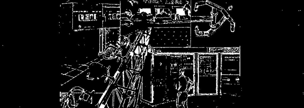


157 SALES & SERVICE


 436-4059 KEITH A.")

 822-1078 MIDWEST JOHN D.")
158 SALES & SERVICE Sales and Service for Continental Electronics Broadcast Transmitters Continental broadcast equipment and existing Collins radio transmitters are serviced by a world -wide Continental field support and marketing group headquartered in Dallas, Texas. All products and prices in this catalog are subject to change without notice. For price or delivery information, contact your Continental representative. 10 District Managers handle sales for stations in the United States. Sales to stations in Canada, Arizona, New Mexico, Utah, Hawaii and Puerto Rico are handled from the home office in Dallas, Texas. International sales are handled thru local sales representatives. A. V. Collins, Vice President/ Domestic Broadcast Marketing E.L. King, Jr., Vice President/ International Broadcast Marketing R.L. Floyd, Manager/ Domestic Broadcast Sales Continental Electronics offers parts and engineering service for all Continental and Collins radio broadcast equipment 24 -hours a day. You can phone our service numbers day or night. (214) parts (214) service Telex: Cable: CONTRONICS Continental Electronics Mfg. Co South Buckner Boulevard PO Box ; Dallas, Texas Ph: (214) Domestic District Managers NORTHEAST MARK F. HUTCHINS P.O. BOX 13 GREENLAND, NH (603) KEITH A. LEACH P.O. BOX 16 NEWTON, NJ (201) SOUTHEAST RAY C. EVANS P.O. BOX 143 Al COA, TN (615) DAVE HULTSMAN 2280 ROCKCREEK TRAIL BIRMINGHAM, AL (205) MIDWEST JOHN D. ABDNOUR P.O. BOX 575 STREATOR, IL (815) LLOYD W. COLLINS ROUTE 3, BOX 106 HOLTS SUMMIT, MO (314) JIM LITTLEJOHN 670 NORTH BRANCH RD. MAPLE PLAIN, MN (612) SOUTHWEST STEVE H. SCHOTT P.O. BOX 2008 PLANO, TX (214) NORTHWEST TOM T. CAUTHERS 1215 SE 73rd AVE. PORTLAND, OR (503) WEST STEVE KEATING 7225 HOLLYWOOD BLVD. SUITE 105 HOLLYWOOD, CA (213)


 449-5666 BANGLADESH Shell Co.")


 Ltd.")
 Ph: 5-236322, 5-244465 ICELAND G. Helgason & Melsted, Ltd.")


159 SALES & SERVICE International Sales Representatives ABU DHABI, U.A.E. International Trading Circle Box 592; Sh. Ahmed Bin Hamed Bldg. Hamden Rd. Telex: DHRETO EM ARGENTINA, S.A. CIA Standard Electric Argentina S.A.I.C. Corrientes 311-9th Floor Buenos Aires 1043 Telex: KOBEA AR & Ph: / /4042/4043/7146 AUSTRALIA Rank Electronics Pty Ltd. 60 Rosebank Ave.; Clayton South Victoria 3169; Telex: AA Ph: (03) Suakin St.; Box 2073; Pymble, N.S.W Telex: AA Ph: (02) BANGLADESH Shell Co.; Akbari House; 9H, Motijheel Commercial Area Dacca -2 Telex: 667 VIKING DAC Cable: PARSHELL Ph: BRAZIL Larex Electronica, Ltda Av. N.S. Copacabana, 195, Grupo 1301; Rio de Janeiro Telex: LREX BR Ph: CHILE Raylex Representaciones y Servicios S.A. Box 13373; Santiago Telex: RYLEX CL Ph: TAIWAN 104, ROC Heighten Corp.; Box 46-65; Tai ei Telex: HEIGHTEN; Cable: HEIGHTEN Ph: COLOMBIA, S.A. Auditron, Ltda.; Avenida 9 No Oficina 201; Bogota 2 Ph: , , ; Telex: HEGAS CO EGYPT ARE Electrical & Telecommunications Engineering; 5. Kasr El Nil St.; Cairo Telex: ETSAS; Ph: & ENGLAND Lee Engineering, Ltd; Napier House Bridge St.; Walton -on- Thames; Surrey KT12 1AP; Telex: LEETEK CG Ph: , 5, 6 BELGIUM Eurotech Marketing (Overseas) Ltd. Avenue De La Tanche 2; B Brussels Telex: Ph: HONG KONG Eastern Union (H.K.) Ltd.; Rm. 1725A; Prince Bldg.; Des Voeux Rd., Central Cable: MARENCORP (via RCA) Ph: , ICELAND G. Helgason & Melsted, Ltd.; Box 528 Raudararstig 1, Reykjavik; Telex: 2145 Cable: MELSTED REYKJAVIK Ph: INDIA The National Radio & Electronics Co., Ltd. "Unity House "; 8, Mama Parmanang Marg; Bombay. Telex: NELBOM Cable: NELCOFF Ph: INDONESIA Elektronika Nusantara P.T.; Box 234 /JKT Jakarta, Telex: ELNUSA Ph: / ISRAEL Rapac Electronics Ltd.; Box Tel Aviv Telex: Ph: & ITALY Elco, s.r.l.; Via Del Sansovino, 6 Rome. Ph: & Telex: JORDAN W.R. Abdul -Hadi & Co.; Box 855 Amman. Telex: 1266 MEKANO JO Cable: MEKANO Ph: MEXICO Servicios En Communicaciones Electricas y Electronica, S.A.; Sta. Eduwiges 2819 Primer Piso; Guadalajara, Jalisco Telex: Ph: & MEXICO, CENTRAL AMERICA & COLOMBIA National Products Co., Inc; 8809 Grenore; Dallas, Texas Ph: MOROCCO Etablissements Hubert Dolbeau & Fils; Boite Postale 133; Casablanca Telex: M; Cable: MATERIO Ph: / NETHERLANDS ANTILLES Industrial Electronics (Antilles) N.V. Centro Comerical Antilia 1; Curacao Telex: 1125 INDELNA; Cable: INDELECA Ph: & NEW ZEALAND Pacific Communications Systems, Ltd. CNR. Fleet & Macaulay St.; Box 460 Auckland. Telex: (NO ANSWERBACK) Ph: or Southern Cross Cresent; Box 227 Wellington. Telex: 3353 ANSERWN NZ Ph: & NIGERIA RMP Telecommunications; Royal London; 22/25 Finsbury Sq.; London, EC2P England. Telex: "STEEL" Cable: MINPLAN LONDON EC2 Ph: PAKISTAN The Modern Trading Co.; Box 7103, Mahboob Chambers; Karachi 3. Cable: MODERTRACO; Telex: LINTA PU Ph: REPUBLIC OF PANAMA Tropelco. S.A.; Apartado 8465; Panama 7 Telex: 3318 TROPELCO PG; Cable: TROPELCO Ph: & PERU Fernando Ezeta B. s.r.l.; Casilla 3061 Lima. Telex: PE SULCOSA Cable: FEPERU Ph: PORTUGAL Soc. Com. Crocker, Delaforce & Co. Box 2738; 1118 Lisboa Codex; Lisbon. Telex: CRODEL P Ph: ,2, 3, 4 QATAR Al Nasr Trading Organization; Box 28 Doha. Telex: 4242 ALNASR DH; Ph: Cable: ALNASR DOHA SINGAPORE & BRUNEI Anrite Aviation Co., Pty. Ltd.; 508 West Camp, Seletar Airport; Box 53; Jalan Kayu Post Office; Singapore 28. Cable: ANRITE Telex: AVION RS Ph: /79 SOUTH AFRICA Communications Technology (Pty.) Ltd. Box 1030; Kempton Park Telex: Ph: (011) SPAIN Busling, S.A.; Orense 24; Madrid -20. Telex: 42435; Cable: BUSLING SA Ph: SUDAN FOM Trading Co.; Box 1876; Khartoum Telex: 626 FOM KM; Ph: & THAILAND Siam Teltech Co. Ltd.; Box 2718; 29/3 Saladaeng S011 Rd.; Bangkok. Telex: TH2631; Cable: SITECO BANGKOK Ph: TRINIDAD & TOBAGO Edgar H. Borde Ltd.; Box 897; Port -of- Spain. Telex: 3481 BORAD Cable: BORAD, Trinidad Ph: , 4773 URUGUAY Farell & Boix Ltda.; Coronel Alegre 1222 Montevideo. Telex: 822 DEAMSAL UY Ph: VENEZUELA Corporacion Electronica, S.A.; Apartado Correos ; Caracas. Cable: CORELSA Telex: CPBTH VE ATTN: CORELSA Ph: , & ZAMBIA International Aeradio (Zanibia) Ltd. Box 31253; Lusaka. Telex: ZA Cable: INTAERIO; Ph: &


160 SALES & SERVICE I f )1 1
161 ,ne,.im..+r 1 r


162 Continental Electrónics Mfg.-Co. Box Dallas, Texas (214) (
Continental's 816R -5B, 35 kw Single Tube Broadcast Transmitter. Includes the 802A solid -state exciter
 Continental's 816R -5B, 35 kw Single Tube Broadcast Transmitter Includes the 802A solid -state exciter LED status indicators Features SCR Power Control Automatic RF Power Output Control Automatic SWR Circuit
State of the Art AM Introducing the Power Rock 828D/E from Rockwell -Collins
 State of the Art AM Introducing the Power Rock 828D/E from Rockwell -Collins I The Power Rock SUPERIOR AUDIO PERFORMANCE DESIGNED WITH STEREO IN MIND EARN Modulation a., This oscilloscope photograph, showing
5/1.0 kw AM Transmitter
 5/1.0 kw AM Transmitter Collins' 820E /F -1 series of broadcast transmitters is one of the most extensively transistorized series of transmitters available in the 5 -kw to 10 -kw power range. The series
Nautel Limited FM 3.5 kw, 5 kw, 8 kw Totally Solid State FM Broadcast Transmitters
 RUGGED SOLID STATE MODULAR DESIGN No tubes to replace No routine tuning or adjustments 65% typical overall efficiency NAUTEL PATENTED COMBINING TECHNIQUE Failure isolation between PA's Multiple power amplifier
1 KW TOTALLY SOLID STATE DIFFERENTIAL GPS TRANSMITTER ( khz)
") GPS1000 1 KW TOTALLY SOLID STATE DIFFERENTIAL GPS TRANSMITTER (282-326 khz) NAUTEL has developed the GPS1000 as an extremely efficient and highly reliable transmitter especially suited for use at remote
GPS1000 1 KW TOTALLY SOLID STATE DIFFERENTIAL GPS TRANSMITTER (282-326 khz) NAUTEL has developed the GPS1000 as an extremely efficient and highly reliable transmitter especially suited for use at remote
25, 50 and 100 kw Digital Solid-State AM Transmitters
 3DX AM Transmitter Family 25, 50 and 100 kw Digital Solid-State AM Transmitters The Harris 3DX family comprising 25, 50 and 100 kw models provides an all-new level of performance, efficiency and peace
J kw AM Transmitter
 J1000 1 kw AM Transmitter J1000 1 kw AM Transmitter J1000 1kW AM Transmitter GREAT THINGS REALLY DO COME IN SMALL PACKAGES. The J1000 transmitter provides excellent functionality and flexibility for the
XR kw AM Medium Wave Broadcast Transmitter
 XR12 12 kw AM Medium Wave Broadcast Transmitter XR12 12 kw AM Medium Wave Broadcast Transmitter XR Series Power Module POWERFUL BUILDING BLOCKS The building block for the XR12 is a power module integrating
TECHNICAL DESCRIPTION
 TECHNICAL DESCRIPTION A.M. BROADCAST TRANSMITTER SENDER AM 3000 SS June 2001-1- Rev. B TRANSMITTER CHARACTERISTICS 1. BASIC OFFER The basic offer includes: One AM3000SS A.M. Medium Wave Solid State Broadcast
FREQUENCY AGILE FM MODULATOR INSTRUCTION BOOK IB
 FMT615C FREQUENCY AGILE FM MODULATOR INSTRUCTION BOOK IB1215-02 TABLE OF CONTENTS SECTION SUBJECT 1.0 Introduction 2.0 Installation & Operating Instructions 3.0 Specification 4.0 Functional Description
KWM-2/2A Transceiver THE COLLINS KWM-2/2A TRANSCEIVER
 KWM-2/2A Transceiver Click the photo to see a larger photo Click "Back" button on browser to return Courtesy of Norm - WA3KEY THE COLLINS KWM-2/2A TRANSCEIVER Unmatched for versatility, dependability and
NA100 NA200 NA300. NA Series Frequency Agile Medium Wave Broadcast Transmitters
 NA100 NA200 NA300 NA Series Frequency Agile Medium Wave Broadcast Transmitters Making Digital Radio Work. Nautel NA100, NA200 & NA300 Quick Specs Field tunable to any frequency in the medium wave band
1 NW BROADCAST TRANSMITTER
 www.americanradiohistory.com 1 NW BROADCAST TRANSMITTER cuit complexities (See Picture 2). Extremely stable low temperature coefficient crystals in conjunction with the highly perfected oscillator design
TX5KPS - TX10KPS 5 and 10 KW Hot-Pluggable version
 TX5KPS - 5 and 10 KW Hot-Pluggable version FM Solid State Power Amplifier 87.5-108 MHz range Built-in RF power combiner and splitter. Each power amplifier module has its own with switching power supply.
COLLINS 20T 1000/500 WATT AM BROADCAST TRANSMITTER
 COLLINS 20T 1000/500 WATT AM BROADCAST TRANSMITTER TJIee COLLINS 20T 1 0 0 0 / 5 0 0 W A T T AM BROADCAST TRANSMITTER high fidelity performance low no a and di-tortion vertical chassis construction recycling
PLUG N PLAY WATT DIGITAL FM TRANSMITTER. April, 2002 IM No
 PLUG N PLAY 1000 1000 WATT DIGITAL FM TRANSMITTER April, 2002 IM No. 597 9972 OPERATION/FEATURE PROGRAMMING. The PNP 1000 allows the user to select many types of different operating parameters and features.
9007 Power Tube. VHF Linear Power Amplifier Tube 33 Kilowatt Peak Sync Output Thru VHF-TV Band
 9007 Power Tube VHF Linear Power Amplifier Tube 33 Kilowatt Peak Sync Output Thru VHF-TV Band 14 db Gain High Gain-Bandwidth Products Efficient Forced-Air Cooling Full Input to 400 MHz CERMOLOX Construction
MODEL AF200A: FM, FM/SCA RECEIVER/MONITOR OPERATION MANUAL
 MODEL AF200A: FM, FM/SCA RECEIVER/MONITOR OPERATION MANUAL THE AF200A IS AN FM AND FM/SCA PROFESSIONAL STYLE RECEIVER/ MONITOR. IT S MANY APPLICATIONS INCLUDE STATION MONITORING AND EAS MONITORING. The
SC1000 DGPS USCG Dual Transmitter
 Southern Avionics Company's DGPS Reference Station Transmitter System. Model: SC1000 DUAL USCG SC1000 DGPS USCG Dual Transmitter QUALIFICATIONS: Meets applicable requirements of the United States Coast
TQCYkDi. HARRIS AND COMMUNICATIONS INFORMATION HANDLING
 TQCYkDi RTaa3CM(M@TZ a@21210.tiq_i@z W COMMUNICATIONS AND INFORMATION HANDLING INTRODUCTION The Harris Corporation - Broadcast Products Division proudly presents its first catalog devoted exclusively to
MI HARRIS ENGINEERING REPORT DESIGN OF A COMPLETELY SOLID STATE 1 KW AM BROADCAST TRANSMITTER COMMUNICATIONS AND INFORMATION HANDLING
 ENGINEERING REPORT DESIGN OF A COMPLETELY SOLID STATE 1 KW AM BROADCAST TRANSMITTER MI HARRIS 11 COMMUNICATIONS AND INFORMATION HANDLING F DESIGN OF A COMPLETELY SOLID STATE 1 KW AM BROADCAST TRANSMITTER
BROADCAST EOUIPMENT RADIO CORPORATION OF AMERICA. ENGINEERING PRODUCTS DEPARTMENT, Camden, N. J., U. S. A.
 BROADCAST EOUIPMENT RADIO CORPORATION OF AMERICA ENGINEERING PRODUCTS DEPARTMENT, Camden, N. J., U. S. A. 50 KW FM Transmitter Type BTF- 5 0A Equipment Specification AS-604 EFFECTIVE JULY, 947 50 KW FM
LBI-30398N. MAINTENANCE MANUAL MHz PHASE LOCK LOOP EXCITER 19D423249G1 & G2 DESCRIPTION TABLE OF CONTENTS. Page. DESCRIPTION...
 MAINTENANCE MANUAL 138-174 MHz PHASE LOCK LOOP EXCITER 19D423249G1 & G2 LBI-30398N TABLE OF CONTENTS DESCRIPTION...Front Cover CIRCUIT ANALYSIS... 1 MODIFICATION INSTRUCTIONS... 4 PARTS LIST AND PRODUCTION
8988 Power Tube. Linear Beam Power Tube
 8988 Power Tube Linear Beam Power Tube CERMOLOX Tube High Gain-Bandwidth Product Full Input to 400 MHz 7000 W Peak Sync. Output Through VHF-TV Band with 16 db Gain The BURLE 8988 is designed specifically
Technical Equipment Specification
 STATE OF CALIFORNIA Office of the State Chief Information Officer Public Safety Communications Division Technical Equipment Specification Equipment Type: Transmitter/Receiver Mobile Relay/Base/Control
VHF LAND MOBILE SERVICE
 RFS21 December 1991 (Issue 1) SPECIFICATION FOR RADIO APPARATUS: VHF LAND MOBILE SERVICE USING AMPLITUDE MODULATION WITH 12.5 khz CARRIER FREQUENCY SEPARATION Communications Division Ministry of Commerce
MSE M A G N E T I C S O U N D E N H A C E R. Passion
 Passion for F M &T V Broadcasting MOZART Series Green RF tecnology High Efficiency 120W to 5000W Compact and Modular FM Transmitters Tr MSE M A G N E T I C S O U N D E N H A C E R TECHNICAL CHARACTERISTICS
Collins Broadcast, Equipment
 Broadcast Equipment Collins Broadcast, Equipment TABLE OF CONTENTS AM Transmitters 2 Tape Equipment 91 Phasing 12 Microphones 102 FM Transmitters 17 Studio Accessories 106 Antennas 32 Measuring, Monitoring
ERICSSONZ LBI-30398P. MAINTENANCE MANUAL MHz PHASE LOCKED LOOP EXCITER 19D423249G1 & G2 DESCRIPTION TABLE OF CONTENTS
 MAINTENANCE MANUAL 138-174 MHz PHASE LOCKED LOOP EXCITER 19D423249G1 & G2 TABLE OF CONTENTS Page DESCRIPTION... Front Cover CIRCUIT ANALYSIS...1 MODIFICATION INSTRUCTIONS...4 PARTS LIST...5 PRODUCTION
PDi COMMUNICATIONS, INC.
 12 in 1 MULTI MOD SAW FILTERED FIXED CHANNEL MODULATOR SYSTEM PDI-50121CM RF SECTION AUDIO SECTION Frequency Range Channel 2-134 (54 to 860MHz) Input Level 250mV minimum for Channels VHF, CATV (STD) 25kHz
Synthesized Base Station Transmitter
 BST-25 OPERATOR S MANUAL (216 MHz) Synthesized Base Station Transmitter 357 West 2700 South Salt Lake City, Utah 84115 Phone: (800) 496-3463 Fax: (801) 484-6906 http://www.comtek.com INTRODUCTION BST-25
FM TRANSMITTERS TESTS
 FM TRANSMITTERS TESTS - FACTORY TESTS - SITE TESTS Page 1 of 11 I. FACTORY TEST (on dummy load) TX s.n... Exciter no...(s.n...) Date... Page 2 of 11 1.PERFORMANCE A) OPERATING FREQUENCY Carrier stability:
Broadcasting MSE M A G N E T I C S O U N D E N H A C E R. Passion
 Passion for F M &TV Broadcasting MOZART Series Green RF tecnology High Efficiency 300W to 5000W Compact and Modular FM Transmitters Tr MSE M A G N E T I C S O U N D E N H A C E R TECHNICAL CHARACTERISTICS
Basic Harris DX Transmitter Tutorial
 BASIC DX TUTORIAL Basic Harris DX Transmitter Tutorial Basic DX Theory The Harris DX Transmitters series, introduced in 1986, have proven to be the most efficient method of Amplitude Modulation at medium
I :NO 1111Z7 :4 TRANSMITTERS PHASING MONITORING TOWERS LINES TRANSMITTING EQUIPMENT
 I :NO 1111Z7 :4 TRANSMITTERS PHASING MONITORING TOWERS LINES TRANSMITTING a 0 EQUIPMENT AM RADIO TRANSMITTING EQUIPMENT CATALOG THE MOST TRUSTED NAME IN ELECTRONICS Copyright 1967 Radio Corporation of
FMR622S DUAL NARROW BAND SLIDING DE-EMPHASIS DEMODULATOR INSTRUCTION BOOK IB
 FMR622S DUAL NARROW BAND SLIDING DE-EMPHASIS DEMODULATOR INSTRUCTION BOOK IB 1222-22 TABLE OF CONTENTS SECTION 1.0 INTRODUCTION 2.0 INSTALLATION & OPERATING INSTRUCTIONS 3.0 SPECIFICATIONS 4.0 FUNCTIONAL
LBI-4938C. Mobile Communications MASTR II POWER AMPLIFIER MODELS 4EF4A1,2,3. Printed in U.S.A. Maintenance Manual
 C Mobile Communications MASTR II POWER AMPLIFIER MODELS 4EF4A1,2,3 Printed in U.S.A. Maintenance Manual TABLE OF CONTENTS DESCRIPTION.................................................... 1 CIRCUIT ANALYSIS.................................................
2.1 Performance Standards The UPS is designed with the applicable sections of UL, CUL, and ISO The UPS has UL and CUL listing.
 1.0 Scope This document describes the specification for Toshiba 1000 Series On-Line Uninterruptible Power System (UPS). The UPS will supply a computer grade AC output sine wave which is unaffected by the
MC2301. Features and Benefits. Promotional Highlights TUBE POWER AMPLIFIER MCINTOSH LABORATORY INC., 2 CHAMBERS STREET, BINGHAMTON, NEW YORK 13903
 MC2301 Product Preview Page 1 McIntosh Laboratory, Inc., Binghamton, NY 13903 Design Engineering Department PRODUCT PREVIEW MC2301 TUBE POWER AMPLIFIER Project 1336 Promotional Highlights 300 Watts Mono
POWER AMPLIFIER. Owner s Manual Mode d emploi Bedienungsanleitung Manual de instrucciónes CLIP SIGNAL TEMP PROTECTION POWER
 POWER AMPLIFIER Owner s Manual Mode d emploi Bedienungsanleitung Manual de instrucciónes TEMP PROTECTION POWER A CLIP SIGNAL B ON OFF M Introduction Thank you for purchasing a Yamaha C450/320/160 series
MODEL 3 MONO AMPLIFIER OWNER S MANUAL
 MODEL 3 MONO AMPLIFIER OWNER S MANUAL TABLE OF CONTENTS Introduction Features Unpacking Instructions Installation * Space requirements * A.C. connections Input Impedance Selection Adjustable Gain Signal
MGM 3000X Q67000-A5179 P-DSO-20-1 (SMD) MGM 3000X Q67006-A5179 P-DSO-20-1 Tape & Reel (SMD)
 MGM 3000X Q67006-A5179 P-DSO-20-1 Tape & Reel (SMD)") Video Modulator for FM/AM-Audio MGM 3000X Bipolar IC Features FM- and AM-audio modulator Audio carrier output for suppression of harmonics Sync level clamping of video input signal Controlling of peak
Video Modulator for FM/AM-Audio MGM 3000X Bipolar IC Features FM- and AM-audio modulator Audio carrier output for suppression of harmonics Sync level clamping of video input signal Controlling of peak
SC5307A/SC5308A 100 khz to 6 GHz RF Downconverter. Datasheet SignalCore, Inc.
 SC5307A/SC5308A 100 khz to 6 GHz RF Downconverter Datasheet 2017 SignalCore, Inc. support@signalcore.com P RODUCT S PECIFICATIONS Definition of Terms The following terms are used throughout this datasheet
ADA416-XLR DISTRIBUTION AMPLIFIERS OPERATING AND MAINTENANCE MANUAL
 ADA416-XLR DISTRIBUTION AMPLIFIERS OPERATING AND MAINTENANCE MANUAL Copyright 2015, ATI Audio Inc. DESCRIPTION Your ADA416-XLR provides four independent one-in by four-out circuit groups. A four-output
PCN-1800 Series. VHF TV Transmitter. 2nd Edition
 PCN-1800 Series VHF TV Transmitter 2nd Edition The Benchmark in Analog TV Broadcasting Compact design and innovative technology establish NEC s new transmitter as the new benchmark in analog TV transmitters.
Summit Audio Model DCL-200 Dual Compressor-Limiter Operating Manual
 Summit Audio Model DCL-200 Dual Compressor-Limiter Operating Manual IMPORTANT!: CAREFULLY READ THE ENTIRE INSTRUCTION MANUAL BEFORE HOOKUP OR OPERATION OF THE DCL-200. WARNING!: HIGH VOLTAGE. THIS UNIT
broadcast MC MARTI N McMartin Industries Inc South 76th Street Omaha. Nebraska (402) Telex
 Telex") broadcast MC MARTI N McMartin Industries Inc. 4500 South 76th Street Omaha. Nebraska 68127 (402) 331-2000 Telex 484485 . r,. v, :. 250-1,500 ` WATT FM TRANSMITTER BF -1M :. E r ^ '. + f E IMAM/MN 1111.11,4
broadcast MC MARTI N McMartin Industries Inc. 4500 South 76th Street Omaha. Nebraska 68127 (402) 331-2000 Telex 484485 . r,. v, :. 250-1,500 ` WATT FM TRANSMITTER BF -1M :. E r ^ '. + f E IMAM/MN 1111.11,4
Air-Cooled FM Transmitter for Analog and Digital Standards
 Air-Cooled FM Transmitter for Analog and Digital Standards The Harris air-cooled FM solid-state transmitter family provides today s broadcaster with a single transmission platform capable of analog and
exciters (OIRT and JPN Band upon request) Features
 Features") PTX30- LCD PTX50- LCD PTX60- LCD PTX100-LCD Mono/Stereo/MPX Professional FM Exciter 87.5-108 MHz 30W, 50W, 60W and 100W (OIRT and JPN Band upon request) Built-in digital signal processing module. 90 signal/noise,
PTX30- LCD PTX50- LCD PTX60- LCD PTX100-LCD Mono/Stereo/MPX Professional FM Exciter 87.5-108 MHz 30W, 50W, 60W and 100W (OIRT and JPN Band upon request) Built-in digital signal processing module. 90 signal/noise,
Broadband Power Amplifier
 601L Broadband Power Amplifier HIGH RF VOLTAGES MAY BE PRESENT AT THE OUTPUT OF THIS UNIT. All operating personnel should use extreme caution in handling these voltages and be thoroughly familiar with
Synthesized Base Station Transmitter
 BST-75 OPERATOR S MANUAL (72-76 MHz) Synthesized Base Station Transmitter 357 West 2700 South Salt Lake City, Utah 84115 Phone: (800) 496-3463 Fax: (801) 484-6906 www.comtek.com TABLE OF CONTENTS Introduction...
Model 7000 Low Noise Differential Preamplifier
 Model 7000 Low Noise Differential Preamplifier Operating Manual Service and Warranty Krohn-Hite Instruments are designed and manufactured in accordance with sound engineering practices and should give
411LA Broadband Power Amplifier
 411LA Broadband Power Amplifier HIGH RF VOLTAGES MAY BE PRESENT AT THE OUTPUT OF THIS UNIT. All operating personnel should use extreme caution in handling these voltages and be thoroughly familiar with
MAINTENANCE MANUAL TRANSMITTER/RECEIVER BOARD CMN-234A/B FOR MLSU141 & MLSU241 UHF MOBILE RADIO TABLE OF CONTENTS
 MAINTENANCE MANUAL TRANSMITTER/RECEIVER BOARD CMN-234A/B FOR MLSU141 & MLSU241 UHF MOBILE RADIO TABLE OF CONTENTS DESCRIPTION... 2 CIRCUIT ANALYSIS... 2 TRANSMITTER... 2 9-Voft Regulator... 2 Exciter...
The Micromega MyAMP. A serious design challenge
 The Micromega MyAMP A serious design challenge Following the successful launch of the MyDAC, MyZIC and MyGROOV, the Micromega engineers had a serious design challenge: to complete the MY range by adding
8101 SPECIFICATION SHEET
 2 5 0 7 W a r r e n S t r e e t, E l k h a r t, I N 4 6 5 1 6 U S A 5 7 4. 2 9 5. 9 4 9 5 w w w. A E T e c h r o n. c o m The AE Techron 8101 power supply amplifier features an advanced switchmode design
.w :16"12- FM Transmitter, 40kIN, Type BTF-40ES1. catalog RA.2071E MEI IM M1 MTh C) 0 Aims E1 sou Q *so
 0 Aims E1 sou Q *so") catalog RA.2071E (Replaces RA.2071D) FM Transmitter, 40kIN, Type BTF-40ES1 r Parallel Transmitters for Ai( The Type BTF-40ES1 is a forty -kilowatt transmitter for the maximum - power FM -broadcast station
catalog RA.2071E (Replaces RA.2071D) FM Transmitter, 40kIN, Type BTF-40ES1 r Parallel Transmitters for Ai( The Type BTF-40ES1 is a forty -kilowatt transmitter for the maximum - power FM -broadcast station
LBI-31564A. Mobile Communications. DELTA - SX MHz RADIO COMBINATIONS (NEGATIVE GROUND ONLY) Maintenance Manual
 Maintenance Manual") A Mobile Communications DELTA - SX 136-174 MHz RADIO COMBINATIONS (NEGATIVE GROUND ONLY) Maintenance Manual TABLE OF CONTENTS MILITARY AND SYSTEM SPECIFICATIONS................................. 2-3 COMBINATION
A Mobile Communications DELTA - SX 136-174 MHz RADIO COMBINATIONS (NEGATIVE GROUND ONLY) Maintenance Manual TABLE OF CONTENTS MILITARY AND SYSTEM SPECIFICATIONS................................. 2-3 COMBINATION
Summit Audio Model EQP-200B Dual Program Equalizer Operating Manual
 Summit Audio Model EQP-200B Dual Program Equalizer Operating Manual IMPORTANT!: CAREFULLY READ THE ENTIRE INSTRUCTION MANUAL BEFORE HOOKUP OR OPERATION OF THE EQP-200B. WARNING!: HIGH VOLTAGE. THIS UNIT
RULEBOOK on the tecnical and exploatation conditions for the frequency modulated emissions of the broadcasting stations
 AGENCY FOR ELECTRONIC COMMUNICATIONS AND POSTAL SERVICES RULEBOOK on the tecnical and exploatation conditions for the frequency modulated emissions of the broadcasting stations Podgorica, April 2010 Further
8121 Power Tube. Linear Beam Power Tube
 8121 Power Tube Linear Beam Power Tube Coaxial-Electrode Structure Ceramic-Metal Seals Full Ratings up to 500 MHz Forced-Air Cooled 170 Watts PEP Output at 30 MHz 235 Watts CW Output at 470 MHz The BURLE
Power Tube. Beam Power Tube
 8977 Power Tube Beam Power Tube - 7 kw Aural Output Through VHF-TV Band - 19 db Gain - CERMOLOX Beam Power Tube - Full Input to 400 MHz - Forced-Air Cooled The BURLE 8977 is intended specifically to meet
5000 Series Receiver Systems
 5000 Series Receiver Systems Modular multi-channel receiver system for demanding musical and broadcast applications Large mainframe houses up to 8 true diversity receiver modules Small mainframe houses
8984 Power Tube. VHF Linear Beam Power Tube
 8984 Power Tube HF Linear Beam Power Tube Full Input to 300 MHz Forced-Air Cooled 55 kw Peak Sync. Output HF-T Band 16dB Gain FM Broadcast Service 55 kw Output 16dB Gain The BURLE 8984 is designed specifically
DA208 & DA416 DISTRIBUTION AMPLIFIERS OPERATING AND MAINTENANCE MANUAL
 DA208 & DA416 DISTRIBUTION AMPLIFIERS OPERATING AND MAINTENANCE MANUAL Copyright 2011, ATI Audio Inc. DESCRIPTION Your DA208 or DA416 provides two (DA208) or four (DA416) independent one-in by four-out
MEDIUM-MU AIR-COOLED POWER TRIODE 3CX15,000H3
 TECHNICAL DATA MEDIUM-MU AIR-COOLED POWER TRIODE 3CX15,000H3 The EIMAC 3CX15,000H3 is an air cooled, ceramic-metal, medium-mu power triode designed primarily for use in broadcast and industrial radio-frequency
Type Ordering Code Package TDA Q67000-A5168 P-DIP-18-5
 Video Modulator for FM-Audio TDA 5666-5 Preliminary Data Bipolar IC Features FM-audio modulator Sync level clamping of video input signal Controlling of peak white value Continuous adjustment of modulation
COLLINS. Broadcast Equipment
 COLLINS Broadcast Equipment Collins Broadcast Equipment - 1966 CONTENTS Collins Radio Company I Disc Equipment 79 AM Transmitters 3 Tape Audio 84 Phasing 12 Microphones 93 FM Transmitters 17 Audio Accessories
5.8 GHz Wireless Video/Audio Transmission link XL-5800/H
 5.8 GHz Wireless Video/Audio Transmission link XL-5800/H EXCELLENT HIGH-POWER MICROWAVE LINK 5.8 GHz WITH FREQUENCY AGILE CHANNELS XL 5800/H is a portable microwave link built-in weatherproof Nema enclosure.
Instruction Manual OM3500 HF SHORTWAVE POWER AMPLIFIER. OM POWER, s. r. o Bác 126 SLOVAKIA
 Instruction Manual OM3500 HF SHORTWAVE POWER AMPLIFIER OM POWER, s. r. o. 930 30 Bác 126 SLOVAKIA Important safety instructions: The amplifier contains high voltage circuits. Never turn the amplifier on
SOUTHERN AVIONICS COMPANY. SE125 Transmitter. SE125 Transmitter 1-1
 1-1 1 Introduction The SE Series transmitters are computer controlled systems designed around an embedded microprocessor. These systems are capable of remote monitoring and maintenance via Ethernet (optional).
Central Electronics Model 600L Linear Amplifier
 INTRODUCTION This manual has been reproduced by James Lawrence, NA5RC, a 600L owner. Text no longer applicable such as insurance claim with the carrier has been deleted. Some capitalization and grammar
Model Quality in Test and Measurement Since 1949 OUTSTANDING PERFORMANCE DESCRIPTION APPLICATIONS ADDITIONAL FEATURES
 Quality in Test and Measurement Since 1949 DC Source/Calibrators, Tunable Electronic Filters, Wideband Power Amplifiers Precision Phasemeters, Distortion Analyzers Function Generators, RC Oscillators Model
Data Sheet SC5317 & SC5318A. 6 GHz to 26.5 GHz RF Downconverter SignalCore, Inc. All Rights Reserved
 Data Sheet SC5317 & SC5318A 6 GHz to 26.5 GHz RF Downconverter www.signalcore.com 2018 SignalCore, Inc. All Rights Reserved Definition of Terms 1 Table of Contents 1. Definition of Terms... 2 2. Description...
ZOTL40 Mk.II POWER AMPLIFIER USER GUIDE. Linear Tube Audio Takoma Park, MD, USA
 ZOTL40 Mk.II POWER AMPLIFIER USER GUIDE Linear Tube Audio Takoma Park, MD, USA WARNING: For safety, the cover of this amplifier should be secured at all times. DC voltages as high as 1000V and peak AC
Power Processor - Series 700F 10KVA to 150KVA
 Power Processor - Series 700F 10KVA to 150KVA Power Conditioning and Regulation for Commercial & Industrial Equipment General Specifications PART 1 - GENERAL 1.1 DESCRIPTION This specification defines
4/30/2012. General Class Element 3 Course Presentation. Practical Circuits. Practical Circuits. Subelement G7. 2 Exam Questions, 2 Groups
 General Class Element 3 Course Presentation ti ELEMENT 3 SUB ELEMENTS General Licensing Class Subelement G7 2 Exam Questions, 2 Groups G1 Commission s Rules G2 Operating Procedures G3 Radio Wave Propagation
87415A microwave system amplifier A microwave. system amplifier A microwave system amplifier A microwave.
 20 Amplifiers 83020A microwave 875A microwave 8308A microwave 8307A microwave 83006A microwave 8705C preamplifier 8705B preamplifier 83050/5A microwave The Agilent 83006/07/08/020/050/05A test s offer
TXM Series TXM SERIES DESCRIPTION
 TXM SERIES DESCRIPTION The FM Transmitters of the TXM series are modular equipment built with single Tessera Tech 1 or 2kW Amplifier Modules. The availabale output powers are from 2,5kW up to 40kW thus
Features 100A400AM20. 4kHz 400MHz Class A Portable Full VSWR tolerant CE & RoHS compliant High Efficiency
 Specifications Class A Portable Full VSWR tolerant CE & RoHS compliant High Efficiency Features The Model is a solid-state, self -contained, air-cooled, broadband amplifier designed for applications requiring
MZ2 HEADPHONE AMPLIFIER, PREAMP, & STEREO AMPLIFIER USER GUIDE
 MZ2 HEADPHONE AMPLIFIER, PREAMP, & STEREO AMPLIFIER USER GUIDE Linear Tube Audio Takoma Park, MD, USA WARNING: For safety, the cover of this amplifier should be secured at all times. DC voltages as high
Bel Canto Design evo Digital Power Processing Amplifier
 Bel Canto Design evo Digital Power Processing Amplifier Introduction Analog audio power amplifiers rely on balancing the inherent linearity of a device or circuit architecture with factors related to efficiency,
OWNER S MANUAL CPS 1 / CPS 2 CONTRACTOR PRECISION SERIES
 OWNER S MANUAL CPS 1 / CPS 2 CONTRACTOR PRECISION SERIES CONTENTS Introduction................................................................... 9 Front Panel...................................................................
FREQUENCY SYNTHESIZERS, SIGNAL GENERATORS
 SYNTHESIZED SIGNAL GENERATOR MG3641A/MG3642A 12 khz to 1040/2080 MHz NEW New Anritsu synthesizer technology permits frequency to be set with a resolution of 0.01 Hz across the full frequency range. And
TOSHIBA International Corp
 TOSHIBA International Corp GUIDE SPECIFICATIONS THREE PHASE UNINTERRUPTIBLE POWER SYSTEM TOSHIBA 4200FA 30 kva CT Internal Battery UPS GUIDE SPECIFICATIONS 1 (30 kva CT) 1.0 SCOPE 1.1 System This specification
Model Hz to 10MHz Precision Phasemeter. Operating Manual
 Model 6610 1Hz to 10MHz Precision Phasemeter Operating Manual Service and Warranty Krohn-Hite Instruments are designed and manufactured in accordance with sound engineering practices and should give long
Svetlana 3CX3000F7/8162 High-Mu Power Triode
 High-Mu Power Triode T he Svetlana 3CX3F7/8162 is a high-performance ceramic/metal power triode designed for use in zero-bias, class AB, or class B RF or audio amplifiers. A modern mesh filament is used,
8792 Power Tube. Linear Beam Power Amplifier Tube
 8792 Power Tube Linear Beam Power Amplifier Tube 1000 Watts Peak Sync Output in VHF Translator Service 265 Watt Average-Noise-Power Output with White Noise Loading 300 Watt Power Output in UHF-Linear Telephony
4X150A/7034 Radial Beam Power Tetrode
 4X15A/734 Radial Beam Power Tetrode T The Svetlana 4X15A/734 is a compact radial beam tetrode. The 4X15A is intended for Class AB SSB linear RF amplifier service. It is intended for stationary and mobile
MCMAR11N. Leonard Hedlund. before. the FM Clinic Madison, Wisconsin. Vice President and Director of Research and Development.
 MCMAR11N a presentation by Leonard Hedlund Vice President and Director of Research and Development before the FM Clinic Madison, Wisconsin MCMARTIN a presentation by Leonard Hedlund Vice President and
2100L Broadband Power Amplifier
 2100L Broadband Power Amplifier HIGH RF VOLTAGES MAY BE PRESENT AT THE OUTPUT OF THIS UNIT. All operating personnel should use extreme caution in handling these voltages and be thoroughly familiar with
ULTRA-K Series 600K - he
 5 kva 500 kva ULTRA-K Series 600K - he High Efficiency K-Rated Power Conditioning Transformers Designed to be used with linear or non-linear loads. Applications: Audio / Video Recording Equipment IT Systems
PRACTICE. Amateur Radio Operator Certificate Examination. Advanced Qualification
 Innovation, Science and Economic Development Canada Innovation, Sciences et Développement économique Canada Amateur Radio Operator Certificate Examination Advanced Qualification 2018-06-30 To pass this
PL8877/ 3CX1500A7 High-Mu Power Triode
 PL8877/ 3CX1500A7 High-Mu Power Triode The Penta Laboratories PL8877/3CX1500A7 is a rugged ceramic and metal power triode designed for use as cathode driven Class AB2 or Class B amplifi er in audio or
The G4EGQ RAE COURSE Lesson 9 Transmitters Lesson 8 looked at a simple transmitter exciter comprising of oscillator, buffer and multiplier stages.
 Lesson 8 looked at a simple transmitter exciter comprising of oscillator, buffer and multiplier stages. The power amplifier The output from the exciter is usually very low and it is necessary to amplify
FlexStar HDx. Advanced FM/FM+HD Exciter
 FlexStar HDx Advanced FM/FM+HD Exciter For HD Radio implementation, GatesAir s award-winning FlexStar HDE-200 embedded HD Radio exporter is required. The exporter is typically located at the studio and
B R O A D C A S T TRANSM' EQUI P M E N T FOR AM FM RADIO (THIRD EDITION)
") B R O A D C A S T TRANSM' EQUI P M E N T FOR AM FM RADIO (THIRD EDITION) www.americanradiohistory.com www.americanradiohistory.com BROADCAST AM -FM TRANSMITTING EQUIPMENT CATALOG FM Transmitters Multiplex
B R O A D C A S T TRANSM' EQUI P M E N T FOR AM FM RADIO (THIRD EDITION) www.americanradiohistory.com www.americanradiohistory.com BROADCAST AM -FM TRANSMITTING EQUIPMENT CATALOG FM Transmitters Multiplex
SC5407A/SC5408A 100 khz to 6 GHz RF Upconverter. Datasheet. Rev SignalCore, Inc.
 SC5407A/SC5408A 100 khz to 6 GHz RF Upconverter Datasheet Rev 1.2 2017 SignalCore, Inc. support@signalcore.com P R O D U C T S P E C I F I C A T I O N S Definition of Terms The following terms are used
Model 4402B. Ultra-Pure Sinewave Oscillator 1Hz to 110kHz Typical Distortion of % Serial No. Operating Manual
 Model 4402B Ultra-Pure Sinewave Oscillator 1Hz to 110kHz Typical Distortion of 0.0005% Serial No. Operating Manual 15 Jonathan Drive, Unit 4, Brockton, MA 02301 U.S.A. Tel: (508) 580-1660; Fax: (508) 583-8989
evolution wireless G4 ew 300 G4-Base SK-RC Bodypack Base Set
 1/7 Best choice for your business, top of the class in education. The G4 300 Series uses the power of an increased switching bandwidth of up to 88 MHz. New frequency ranges allow to operate multi-channel