Intelligent Transportation based UWB Positioning and Connectivity
|
|
|
- Sharon Wilcox
- 5 years ago
- Views:
Transcription


1 Intelligent Transportation based UWB Positioning and Connectivity A Proof of Concept for Improving Public Transportation Final Report University at Albany - SUNY Center of Technology in Government 187 Wolf Rd #301, Albany, NY G. Brian Burke bburke@ctg.albany.edu University at Albany SUNY Signals & Networks Lab #LI Washington Avenue, Albany, NY Hany Elgala helgala@albany.edu
2 Table of Contents Table of Contents... 2 Executive Summary... 3 Findings... 3 Recommendations... 4 Cautions... 4 Glossary... 6 Summary... 7 Introduction... 8 The P440 modules from Time Domain... 8 Ranging... 8 Localization... 9 Forming a Network... 9 RangeNet Software... 9 Channel Analysis Tool (CAT) Software... 9 Indoors: Static and Mobile Tunnel Measurements Ranging Scenario A: Optimized Deployment Scenario B: Different Heights Scenario C: Antenna Orientation Scenario D: Relative Position Scenario E: Non-Line-of-Sight Localization Scenario A: Static Measurements using Tripods Scenario B: Mobile Tags on Human Body Outdoors: Static, Bus and Bike Trials Ranging Localization Scenario A: Static Measurements using Tripods Scenario B: Mobile Tags in a Bus and on a Bike Technical Summary and Conclusions Signals & Networks Lab ECE CEAS University at Albany - SUNY 2
3 Executive Summary There are many practical public sector applications of the internet of things (IoT). From smart streetlights that dim at certain hours to sensors in parking garages that connect to a mobile app to help citizens find available parking, the IoT can help. Not only are there different applications of IoT, there are many different types of technologies available within the IoT. Each technology has different strengths and weaknesses depending on its intended use. To help governments make smart public investment decisions in promising yet often unproven products, feasibility studies and proof of concepts are critical. The Center for Technology in Government at the University at Albany (CTG) and UAlbany s College of Engineering and Applied Sciences Signals & Networks Lab partnered with the UAlbany s Parking & Mass Transit and the Office of Facilities Management to study the feasibility of applying ultra-wideband (UWB) technology to public transportation. Ultra-wideband technology is a wireless radio system that uses a small amount of energy to transmit large amounts of data over a wide range of frequency bandwidths, allowing for ranging and localization at the same time. For public transportation, UWB could provide numerous benefits including better tracking of trains and buses, and potentially eliminating the need for turnstiles, tickets or cards to deposit money or swipe for payment. However, the concern among many government officials is that the advertised potential of technologies such as UWB will not meet the demands placed on it within an actual public transportation infrastructure. These demands include specific levels of accuracy, consistency, and resiliency that are required by public transportation authorities to ensure service quality, effectiveness, and safety. This eight month study was designed to help assess the effectiveness of UWB by using a series of experiments that the project team tested within UAlbany facilities and transportation infrastructure. In a series of controlled experiments, we evaluated the feasibility of deploying Ultra-Wide Band (UWB) technology using the following use cases: (1) for determining the location of a train on a track (called ranging in the experiment) and (2) for an electronic payment application, such as a passenger at a turnstile, to determine the ability to locate individuals within crowds (called localization in the experiment). Both cases were tested indoors (tunnel) and outdoors (roadway) to evaluate environmental effects. The experiments measured for reliability (integrity of signal) and precision (range of error in locating) based on impulsive radio UWB (IR-UWB). Our findings, recommendations, and cautions are summarized below. Details follow in the rest of this report. Findings For ranging in the tunnel environments, our results show that in the majority of cases for line-of-sight distances of up to 150m (~164 yds or 1/10 mile) between two UWB nodes, the precision was within 10cm (~4in). For non-line-of-sight distances up to 26m (~28yds) between two UWB nodes, the precision was within 50cm (~20in). For localization in the tunnel environment, our results show precision of within 5cm (~2in) in X and Y positioning for a crowded scenario using six active UWB nodes. We also included the effect of the human body in this mobile scenario and demonstrated precision within 4cm (~1.5in) while locating and tracking two UWB nodes separated by a distance of 20cm (~8in). All nodes were placed within a coverage area equivalent to the area of turnstile gates 3m x 1.2m (~3.3yd x 1.3yd). Signals & Networks Lab ECE CEAS University at Albany - SUNY 3
4 Measurements were also performed outdoors in a very different propagation environment using static UWB nodes on tripods as well as mobile UWB nodes in a bus and mounted on a bike. We confirmed the need for optimization to achieve the targeted performance in different environments and for different applications. Due to signal attenuation along the tunnel according to the distance and the frequency used and due to multi-path effects, radio transmission is subject to several problems. Especially in a severe tunnel environment, a positioning system based on IR-UWB technology has the potential to offer the highest decimeter precision radio based indoor positioning at present with low power consumption, transmission power and other characteristics. In an actual transport tunnel, having no cellular, wireless (WiFi) or GPS helps to reduce possible interference on the detection of the IR-UWB signals. In addition to the electronic payments application, based on the obtained results, we believe that the UWB technology has the potential to offer simultaneous train-to-wayside communication and train location for communication based train control (CBTC) as well as obstacle detection in front of the trains. Thus, it provides a technically effective and economically sensible alternative solution to existing signaling technologies used in urban transport systems. Recommendations Based on the findings above, we recommend further prototyping of IR-UWB in real-world metropolitan public transporation scenarios scenarios with objective monitoring and evaluation of results. Our experiments validate the promise of IR-UWB to satisfy the use case requirements for ranging and localization, but these need to be further tested and affirmed to both extend the scenarios of our controlled lab and to address the cautions noted below. However, based on our initial testing, we do find IR-UWB to be an appropriate and promising solution for metropolitan public transportaion and one worthy of further exploration. Cautions More investigations are needed to study how the technology performs in more real world scenario and associated conditions. Focusing on the tunnel environments, in order to fulfill the objectives requested for a practical CBTC deployments: (1) the characteristics of the train-to-wayside propagation channel will change while the train is moving, thus impacting the reliability of ranging, localization and communication performance. The design (the capabilities and density of UWB transceivers located on the train exterior and wayside) has to be optimized to match these environment changes to ensure reliability in the whole tunnel. (2) the whole transport network (infrastructure and trains) is built over a variety of environments (openspace, subway tunnels, and viaducts), thus the trade-offs between the performance of simultaneous ranging, localization and communication services (use-case scenarios) have to be determined. The additional factors caused by the different dynamics in the tunnel from passengers and existing cellular/wireless enabled mobile devices have to be considered while designing the system, and (3) it is also important to investigate how the scaled-up/extended network wirelessly or through wire-lines is being powered and connected to the cloud. Areas for further system improvement inside the tunnel include (1) Increase transmitter power for extended range, decrease pulse-width for better resolution and optimize antenna design and their number for coverage, (2) Autonomous surveying of the propagation channel inside the tunnel possibly using unmanned aerial vehicles (UAVs), (3) effect of the actual size of trains and their speed on the channel. (4) co-existence with indoor small-cell deployments for cellular and wireless coverage in the tunnel using either licensed or unlicensed spectrum, (5) interference from passengers cellular and wireless devices as well as jamming, and (6) UWB technology deployment inside the train and for device-free sensing. Signals & Networks Lab ECE CEAS University at Albany - SUNY 4
5 Acknowledgements This study was conducted jointly by the UAlbany Center for Technology in Government (CTG) and the SINE lab located at the College of Engineering and Applied Sciences. CTG and the SINE Lab would like to acknowledge the significant contributions made to this study by the UAlbany students who worked with us: Mr. Smit Shilu, masters students in Computer Science; Ms. Priti Pachpande, doctoral student in the Department of Computer Science; and Mr. Ahmed Hussein and Ms. Monette Khadr, doctoral students in the Department of Electrical and Computer Engineering. Finally, we would like to acknowledge and thank the UAlbany Office of Facilities Management and UAlbany Parking & Mass Transit Services for their outstanding and flexible support of this project. The commitment of both departments to UAlbany s research mission allowed our research team to utilize campus facilities and the transit system to take our experiments outside of the lab and into realistic transportation environments. Signals & Networks Lab ECE CEAS University at Albany - SUNY 5
6 Glossary UWB (Ultra-Wideband) unit In this report, we refer to an UWB unit as P440 unit or node. Anchor (fixed unit) Anchor nodes are fixed units in the network with which we get the location of mobile units. Tag (mobile unit) Mobile nodes are the units, which are in motion. And for which the X, Y and Z values are measured. Mobile units are also referred to as tags. SNR Signal-to-noise ratio is defined as the level of a desired signal to the level of background noise. It is the ratio of signal power to the noise power, often expressed in decibels. Ranging Ranging is defined as the distance between two UWB units. Localization It determines the location of a tag relative to the anchors (references). Localization layer allows the user to use either the ALOHA or TDMA network protocols to compute the location of a mobile unit in either 2D (X and Y) or 3D (X, Y, and Z) dimensions. ALOHA The ALOHA network protocol is a totally asynchronous means of allowing an arbitrary and variable number of UWB units to communicate with a minimum of mutual interference. It allows units to announce their presence to the general community of devices and to learn who else is in the area. It also has processes for dealing with units, which enter or leave the neighborhood. The ALOHA network is good for networks in which the total number of units in the network are unknown and those units join and leave the network at unpredictable times. TDMA Time Division Multiple Access (TDMA) network operates by defining specific time windows (slots) in which specific units may communicate with specific units or with all units. This type of network is most useful when the number of units participating in the network is both known and fixed. Each slot contains the definition of the means of communication and the type of message sent. More specifically, for each time slot the user can define: what code channel will be used for the message, which unit will transmit and which unit(s) will receive, which antenna configuration will be used, whether the transmitted packet is a ranging or data packet, Whether and how much data will be transmitted, and whether the unit will enter a sleep mode when not participating in the current slot. Typically, there will be one set of slots for all units in the system. This collection of slots is called a Slot Map. The big advantage of this approach is that it uses every possible moment of time for communications and thereby achieves almost 100% utilization of the system. This is in contrast to the ALOHA-based network, which normally achieves only 35% efficiency. Because it utilizes airtime more efficiently, the TDMA protocol offers higher network capacity. Tx- Here we use this term for transmitter, which can also be known as range responder in ranging experiment. Rx - Here we use this term for Receiver, which can also be known as range requester in ranging experiment. Signals & Networks Lab ECE CEAS University at Albany - SUNY 6
7 Summary The ultra-wideband (UWB) is a very promising wideband technology for high precision indoors and outdoors ranging and localization. UWB systems generally have a bandwidth of the order of a few gigahertz, which potentially provides sub-nanosecond scale resolution in time. When combined with timebased range estimation methods such as time-of-arrival (TOA) or time-difference-of-arrival (TDOA), this property enables UWB to achieve ranging accuracies in the order of few centimeters. UWB can penetrate through obstacles. This is an advantage over the limitations of GPS for indoor usage. However, the radiated power density of UWB signals is limited to control interference on other narrowband wireless technologies such as WiFi. This in turn limits the coverage range of the UWB network despite the advantage over GPS. The Time Domain kit consisted of ten P440 UWB hardware modules and three software tools RangeNet, MRM (Mono-static Radar Module) and CAT (Channel Analysis Tool). For this study, we used the RangeNet for ranging and localization, while the CAT was used to investigate signal propagation through the channel and for channel modeling. This final report includes the results of our experiments conducted in the UAlbany tunnel system and outdoors near the Social Science building bus stop, on the up-town campus of the University at Albany. First, we conducted experiments in the lab in order to become familiar with the hardware and software capabilities of the kit as well as the configuration, post-processing, and data-display environments. Accordingly, hardware and software settings as well as anchors and tags placement and orientation are optimized (see previous progress report). We use four fixed P440 units as anchors and other P440 units as mobile tags. We considered different numbers of mobile tags being served by the four anchors starting from a single tag and up to six tags. Initially, we considered two different protocols, ALOHA and time-division multiple access (TDMA), to establish the network between anchors and tags. Errors estimating the location of the different tags are higher for ALOHA compared to the TDMA option; estimated location readings are also more stable. Although, there is room for improvement, we decided to proceed with the TDMA to stay on schedule. After the lab experiments, we moved into the UAlbany tunnel and then went outdoors. We took measurements to study ranging and localization performance (accuracy, reliability and coverage) for different line-of-sight (LOS) and the non-line-of-sight (NLOS) scenarios. While still targeting accuracy, reliability and coverage, we also measured the error in distance between mobile tags on the human body. We conducted ranging experiments (on tripods, inside a bus, and on a bike) up to 150m inside the tunnel and up to 450m outdoors. For all scenarios, we took 500 readings for ranging and localization. For localization, we considered scenarios emulating the area of turnstile gates. We varied several parameters to understand the effect on the performance. Signals & Networks Lab ECE CEAS University at Albany - SUNY 7


8 Introduction The P440 modules from Time Domain The P440 module shown in Figure 1 coherently transmits and receives ultra-wideband (UWB) pulses. These pulses are transmitted over RF frequencies between 3GHz and 5GHz supporting 1.4GHz bandwidth. Pseudo-random encoding of the transmission allows the creation of independent channels. This allows multiple modules to be operated on different channels in the same area, at the same time and with a minimum of mutual interference. Depending on how the pulses are transmitted and received, the modules can be used as a range measurement device, a data link, an impulse transceiver for channel modeling, monostatic radar, bi-static radar, multi-static radar, or some combination of the above. The device s operating mode is software-defined. The RangeNet software uses UWB pulses to measure range and to communicate. Other Time Domain software packages use UWB pulses for radar and channel modeling. In this report, the UWB modules are referred as nodes, units or P440 modules. Ranging Figure 1 The P440 module. UWB ranging is normally performed using two-way time-of-flight (TW-TOF) distance measurement. With this approach, a packet is sent from one unit (the requester) to a second unit (the responder). The responder then transmits a carefully timed response packet that is received by the requester. By knowing the speed of light, the exact time when the request packet was sent, the time it took the responder to send the return packet, and the time when the response packet was received, it is possible to measure the range with 2cm accuracy; some research groups successfully reported accuracy of 2mm using averaging. Such measurements are also called Precision Range Measurements (PRMs). The P440 units also measure the signal strength of the first arriving energy. Since the strength of a signal is inversely proportional to the square of the distance, the signal strength can be used to estimate distance. Because signal strength is also a function of other factors, this estimate is rather coarse and is therefore referred to as a Coarse Range Estimate (CRE). A CRE can be calibrated with periodic PRMs to form a Filtered Range Estimate (FRE). Since other units can hear a transmission from one unit, CREs effectively broadcasted in every transmission will result in a CRE at each receiving unit. This technique can be used to increase the overall performance. Signals & Networks Lab ECE CEAS University at Albany - SUNY 8
9 Localization Since the goal of a network-based ranging system is to determine the location of mobile nodes relative to anchor nodes, Time Domain has added a localization layer to RangeNet. All the computations and commands associated with collecting and converting range measurements to locations are executed in the P440. Nodes are therefore responsible for computing and reporting their positions. Forming a Network While it is useful to measure the range between two units, it is often more valuable to take measurements from a network of units and use that information to compute not just the range between two units but the actual device location in three dimensions. Control and coordination of such network is required. In principle, such a network can be implemented using a wired solution (based on Ethernet or USB) or a wireless solution such as WiFi. However, these types of networks have a serious limitation in that they are designed to maximize data throughput using one-way packets. While that approach is a logical and reasonable approach for handling data, it is not well suited for handling range measurements. This is due to the way in which range is measured. The range measurement process requires the transmission of two carefully timed packets acting as a single conversation. Therefore, the network must be designed to handle conversations and not just simple one-way transmissions. RangeNet Software The RangeNet software has been specifically designed and optimized to handle networks of UWB ranging devices. The RangeNet software supports two-way ranging and communications, as well as operation as a complete ranging network (with ALOHA and TDMA protocols) with a location engine to support navigation and tracking applications. While RangeNet can transport data, the associated data rates and throughput are of secondary interest and are normally limited to rates consistent with command and control functions. Channel Analysis Tool (CAT) Software The channel analysis tool (CAT) software allows P440 users to view and log UWB RF waveforms as they propagate through an RF channel. These captured waveforms represent the impulse response of the environment. They can be used as a propagation tool to develop a channel model or as bi-static or multistatic radar. Signals & Networks Lab ECE CEAS University at Albany - SUNY 9

 to observe the calculated/estimated range distance between the Tx and Rx in real-time.")
10 Indoors: Static and Mobile Tunnel Measurements Ranging For the ranging experiments in the tunnel, we used the Ranging tab in RangeNet software. As shown in Figure 2, the basic tunnel deployment for ranging experiment is sketched. Figure 3shows an actual picture inside the tunnel, where the experimental measurements are taken. As shown in Figure 3, there are metallic objects such as cabinets, pipes and carts affecting the signal propagating between the transmitter (Tx) and the receiver (Rx). We use a laptop (attached to the Rx) to observe the calculated/estimated range distance between the Tx and Rx in real-time. We took measurements for different scenarios, as follows: Scenario A: LOS ranging at 100m and 150m, where the Tx and the Rx deployment is optimized. Scenario B: LOS ranging at 150m, with a 1ft. (~0.3m) height difference between the Tx and Rx. Scenario C: LOS ranging at 150m, while changing antenna orientation using 45 degrees intervals. Scenario D: LOS ranging at 150m, where the Tx and the Rx are not directly aiming at each other; lateral displacement. Scenario E: NLOS ranging at 17m and 26m, where the Tx and the Rx are placed at relatively different positions. For tunnel ranging measurements, we are limited by the structure of the tunnel. Thus, we can only go up to 150 m for ranging experiment. Figure 2 LOS ranging measurements: sketch. Figure 3 LOS ranging measurements: actual picture. Table 1 Settings for ranging trials inside the tunnel. Transmit Gain 63dB Antenna Mode Pulse Integration Index (PII) Scan mode Sleep Mode Code Channel 0 Antenna Orientation Port A Pulses Full Scan mode Active Up Signals & Networks Lab ECE CEAS University at Albany - SUNY 10
11 For all ranging scenarios inside the tunnel, settings are listed in Table 1 and are explained as follows: Transmit Gain: This controls the magnitude or strength of transmitted pulses. When used with a standard Time Domain Broadspec antenna, an entry of 63 will produce an output signal equal to the maximum transmit power allowed under either the Region 1 (FCC) or Region 2 (EU/ETSI standard) Setting this value to 0 will reduce the transmit power by up to 30dB. The settings have been calibrated at 63 but not at other settings. For a P440, settings between 0 and 63 are monotonic but are not necessarily linear. For example, a setting of 40 on one unit will not necessarily produce the same signal strength as a 40 on a different unit. Antenna Mode: This drop-down window controls which antenna port will be used to transmit and which will be used to receive. There are 4 choices: Transmit on A, Receive on A. Transmit on B, Receive on B. Transmit on A, Receive on B. Transmit on B, Receive on A. Pulse Integration Index (PII): This drop-down selection is used to set the number of pulses, which will be coherently integrated to form a single symbol. Each time the Pulse Integration Index (PII) is increased by 1 step, the number of pulses per symbol will be doubled. This has two effects. First, the transmitted packet will take twice as long to send. Second, the received signal strength will increase by 3dB. Units operating with different PIIs will not be able to communicate. Scan Mode: In Full Scan mode, 1632 measurements will be reported. This corresponds to a waveform 99.5ns long with ~90ns prior to the pulse and 10ns after the pulse. Sleep Mode: Each member of the P4xx family supports various sleep modes. The advantage of sleep modes is that they allow the unit to power off different parts of circuitry to save energy. Not all P4xx units support all of the sleep mode states. Code Channel: This is the communications channel over which the unit transmits and receives. This is analogous to channel numbers on a UHF radio or on a television. Units operating on different channels will not be able to communicate. While other numbers can be entered, the only valid values are 0 through 10. Antenna Orientation: Those interested in the best accuracy possible should be aware that the orientation of the antenna could change the bias by 4cm. If the antennas on the requester and responder are both pointed in the same direction (both up or both down) then there will be no change in bias. However, if one antenna is pointing up and the other is pointing down, then the pulse being transmitted is inverted in phase. This will cause the 4 cm change in bias. If such a difference is important to your application, then the solution is to set the Ant Orientation field to reflect how the antenna will be mounted. The default is A/B up. Throughout the report, we show the calculated deviation from the actual range or values of X, Y and Z in localization. The deviation is the error in the estimated values of range and location relative to the actual values. Accordingly, we use the term relative error and report the values in percentage (on figures) as well as in centimeters (in text or tables). We save 500 readings for each measuring session. Theoretically, we need between 1-2 minutes to conduct a session. For the majority of reported figures, we show the distribution in terms of the occurrence in percentage of relative error within the 500 readings. We also report the values in centimeters for relative error having maximum percentage of occurrence as well as the range of occurrence for the relative error. Signals & Networks Lab ECE CEAS University at Albany - SUNY 11


12 Scenario A: Optimized Deployment In this scenario, Tx and Rx are placed 7ft (~2.1m) above floor level. Orientation of antenna is at 0 degrees for both Tx and Rx; directed alignment. As shown in Figure 4 and Figure 5, the relative error having maximum assurance for 100m is about 0.7cm and about 5.3cm for 150m. Range of error for 100m is around cm and around 3-24cm for 150m. Increasing the distance between the Tx and Rx leads to higher attenuation on the LOS component and more multipath components due to the increase of the number of metallic objects such as cabinets, pipes and carts. The RangeNet software gives an error message for calculated values outside the targeted accuracy range. Figure 4 LOS tunnel ranging trials at 100m and 150m; optimized deployment. Scenario B: Different Heights Figure 5 Zoom in optimized deployment. In scenario B, we only consider the case of 150m between the Tx and Rx. The Tx and Rx are placed at different heights; 6ft and 7ft, respectively. Again, orientation of antenna is at 0 degrees for both Tx and Rx; Signals & Networks Lab ECE CEAS University at Albany - SUNY 12

13 directed alignment. As shown in Figure 6 and Figure 7, range of relative error for Tx and Rx at different heights is around cm. The relative error having maximum occurrence is about 9.8cm. Comparing Figure 4 and Figure 6 as well as Figure 5 and Figure 7, we can conclude that the difference in height changes the distribution as well as the range in relative error readings. Figure 6 LOS tunnel ranging trials at 150m; 1ft height difference. Scenario C: Antenna Orientation Figure 7 Zoom in 1ft height difference. In Figure 8 and Figure 9, the ranging performance is shown as a function of antenna orientation, where Rx angle is varied at an interval of 45 o. Accordingly, the intervals for measurements are 0 o, 45 o, 90 o, 135 o, 180 o, 225 o, 270 o and 315 o. The Tx and Rx are only able to reliably see each other at 0 o ; no reading errors. For 45 o, and in 45.5% of the readings, the Tx is not able to respond to Rx and the relative error having maximum occurrence is about 9.8cm. For 90 o, and in 14% of readings, the Tx is not able to respond to Rx and the relative error having maximum occurrence is about 25.5cm. For 135 o, and in 15.5% of the readings, the Tx is not able to respond to Rx and the relative error having maximum occurrence is about 34.5cm. For 180 o, and in 13.5% of the readings, the Tx is not able to respond to Rx and the relative error having Signals & Networks Lab ECE CEAS University at Albany - SUNY 13


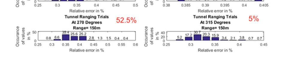
14 maximum occurrence is about 30cm. For 225 o, and in 50.5% of the readings, the Tx is not able to respond to Rx and the relative error having maximum occurrence is about 49.5cm. For 270 o, and in 52.5% of the readings, the Tx is not able to respond to Rx and the relative error having maximum occurrence is about 58.5cm. Finally, and for 315 o, and in 5% of the readings, the Tx is not able to respond to Rx and the relative error having maximum occurrence is about 52.5cm. For example, and for the worst case at 270 o, the range of error is cm. After obtaining these results, we decided to keep the orientation of both antennas at 0 degrees. Figure 8 LOS tunnel ranging trials at 150m; difference antenna orientation. Figure 9 Zoom in difference antenna orientation. Signals & Networks Lab ECE CEAS University at Albany - SUNY 14
 apart. Figure 10 LOS tunnel ranging trials at 150m. Tx fixed at Position 1 and different positions of Rx. The ranging performance is shown in Figure 11.")
15 Scenario D: Relative Position As shown in Figure 10, the Tx is at fixed Position 1 and measurements are taken by placing the Rx at Positions 1, 2, 3 and 4, respectively. All positions are 1.5ft (~0.45m) apart. Figure 10 LOS tunnel ranging trials at 150m. Tx fixed at Position 1 and different positions of Rx. The ranging performance is shown in Figure 11. For the different positions, the relative error generated is different. In Position 1 and Position 2, the relative error is less and a LOS scenario is assumed. However, in Positions 3 and 4, the relative error changes as the units gets near to metallic objects, where error may generate due to multipath propagation of the signals. Table 2 lists the maximum occurrence and range of relative error for the considered scenarion of a moving Rx. Figure 11 Relative error readings when Tx and Rx are not directly facing each other; Rx moving. Signals & Networks Lab ECE CEAS University at Albany - SUNY 15
 apart.")
16 Table 2 Maximum occurrence and range of relative error; Rx moving. Position Maximum occurrence of relative Range of relative error (cm) error (cm) As shown in Figure 12, the Rx is at fixed Position 1 and measurements were taken by placing the Tx at Positions 1, 2, 3 and 4, respectively. All positions are 1.5ft (~0.45m) apart. Figure 12 LOS tunnel ranging trials at 150 m. Rx fixed at Position 1 and different positions of Tx. The performance is shown in Figure 13. Table 3 lists the maximum occurrence and range of relative error for the considered scenarion of a moving Tx. Figure 13 Relative error readings when Tx and Rx are not directly facing each other; Tx moving. Signals & Networks Lab ECE CEAS University at Albany - SUNY 16
17 Table 3 Maximum occurrence and range of relative error; Tx moving. Position Maximum occurrence of relative Range of relative error (cm) error (cm) From Figure 11 and Figure 13, we can conclude that the relative positions of Tx and Rx affect the ranging performance. For best performance, it is recommended to place the Tx and Rx in a LOS scenario, where the antennas are 2 ft (~0.6m) away from any metallic surface. Scenario E: Non-Line-of-Sight As shown in Figure 14, the Rx is at fixed Position 1 and measurements were taken by placing the Tx at Positions 1, 2, 3 and 4, respectively. All positions are 1.5 ft (~0.45m) apart. Figure 14 NLOS tunnel ranging trials at 17m. Rx fixed at Position 1 and different positions of Tx. The relative error values at different positions are plotted in Figure 15. In Position 3, and in 7% out of total readings, the Tx is not able to respond to the Rx. In Position 4, and in 14% out of total readings, the Tx is not able to respond to the Rx. Table 4 lists the maximum occurrence and range of relative error for the considered scenario of a moving Tx. Signals & Networks Lab ECE CEAS University at Albany - SUNY 17
18 Figure 15 Relative error readings at 17m when Tx and Rx are not directly facing each other; Tx moving. Table 4 Maximum occurrence and range of relative error; Tx moving. Position Maximum occurrence of relative Range of relative error (cm) error (cm) to to As shown in Figure 16, the Tx is at fixed Position 1 and measurements were taken by placing the Rx at Positions 1, 2, 3 and 4, respectively. All positions are 1.5ft (~0.45m) apart. 17m Figure 16 NLOS tunnel ranging trials at 17 m for Rx fixed at Position 1 and different positions of Rx. The relative error values at different positions are plotted in Figure 17. In Position 4, and in 28% out of total readings, the Tx is not able to respond to the Rx. In Position 4, and in 14% out of total readings, the Tx is not able to respond to the Rx. Table 5 lists the maximum occurrence and range of relative error for the considered scenarion of a moving Rx. Signals & Networks Lab ECE CEAS University at Albany - SUNY 18
19 Figure 17 Relative error readings at 17 m when Tx and Rx are not directly facing each other; Rx moving. Table 5 Maximum occurrence and range of relative error; Rx moving. Position Maximum occurrence of relative Range of relative error (cm) error (cm) to to The same settings in Figure 14 and Figure 16 are considered for 26m instead of 17 m. The associated performance curves are shown in Figure 18 and Figure 19. Table 6 lists the maximum occurrence for the considered scenario of a moving Tx and moving Rx. Signals & Networks Lab ECE CEAS University at Albany - SUNY 19
20 Figure 18 Tunnel ranging trials at 26m. Tx and Rx are not directly facing each other; Tx moving. Figure 19 Relative error readings at 26m when Tx and Rx are not directly facing each other; Rx moving. Table 6 Maximum occurrences of relative error; Tx and Rx moving. Position Maximum occurrence of relative error; Tx moving (cm) Maximum occurrence of relative error; Rx moving (cm) Signals & Networks Lab ECE CEAS University at Albany - SUNY 20
 from center.")

21 Localization Regarding localization in the tunnel, we are using the location tab of RangeNet software. Figure 20 shows the tunnel environment for localization experiment. Anchors are placed at fixed positions. All mobiles are placed within a coverage area equivalent to the area of turnstile gates. The fixed mobiles are placed at 2ft (~0.6m) from center. Settings are listed in Table 7. The scenarios are as follows: Scenario A: Static measurements using tripods to mount both anchor and tag units. Scenario B: Mobility based on placing two mobile tags on a human body; front and back. Figure 20 Actual setup for localization trials inside the tunnel. Table 7 Settings for for localization trials inside the tunnel. Transmit Gain 63dB Antenna Mode Pulse Integration Index(PII) Scan mode Sleep Mode Code Channel 0 Antenna Orientation Anchor Beacon Rate Mobile Beacon Rate Network Mode Solver Type Port A Pulses Full Scan mode Active Up 1000ms 400ms Auto TDMA Kalman Signals & Networks Lab ECE CEAS University at Albany - SUNY 21
22 There are some additional settings compared to Table 1 and are explained as follows: Beacon Rate: This field is used to define the average rate at which anchors or tags communicate. Mobiles will issue range requests at random intervals with a minimum time not less than the time required to complete a range request. Anchors operate in the same manner with two exceptions. First, an Anchor will never issue a range request. Instead, it will transmit a short data packet announcing its existence. Second, every time it receives a range request, it will reset to zero the timer associated with Beacon transmission. Network Mode: This drop-down menu determines if the localizer will operate using the ALOHA, TDMA or auto TDMA protocol. The user has the choice of selecting either TDMA-Slot Map (in which UWB unit will use the Slot Map defined by the user on the Networking Tab) or TDMA-Auto (in which case the RangeNet GUI will define the Slot Map to be used by the UWB unit and use the PII, antenna port, and code channel as defined on the Configuration Tab).When switching back and forth from one of the location modes on the Location Tab (Tracking, Idle or Autosurvey with either ALOHA, TDMA-Slot Map, or TDMA-Auto) to one of the network-only modes on the Network Tab (TDMA or ALOHA), it is necessary to reboot the unit before you will be able to complete the transition. Solver Type: This drop-down menu determines whether the Kalman or Geometric solver will be used. The Location Engine is resident on each node and uses either a Kalman or a Geometric solver to calculate the node s location. Kalman solver - Use this if mobiles are moving. It has a sense of inertia in its model to compute the mobile s location. Geometric solver Use this if mobiles tend to remain stationary (move slowly or is static). It does not use sense of inertia whereas it is more sensitive to noise. Scenario A: Static Measurements using Tripods In this scenario, four nodes are fixed as anchor nodes (purple circles), five tags (green circles) are also placed at fixed positions as shown in Figure 21 and the sixth tag is being located at Positions 1, 2, 3 and 4. Figure 21 Localization setup: coverage area equivalent to the area of turnstile gates. The anchors X, Y and Z values, calculated using auto survey mode, are listed in Table 8. All mobile nodes are placed within a coverage area equivalent to the area of turnstile gates 10ft x 4ft (3m x 1.2m). Signals & Networks Lab ECE CEAS University at Albany - SUNY 22
23 Table 8 Anchor X, Y and Z values. Anchor X(in m) Y(in m) Z(in m) Figure 22 Relative errors in X, Y and Z for Positions 1, 2, 3 and 4. Relative errors in X, Y and Z for Positions 1, 2, 3 and 4 are shown in Figure 22. We can observe that the range of relative error Z values is comparatively larger for all positions. Table 9 lists the error range in X, Y and Z. Signals & Networks Lab ECE CEAS University at Albany - SUNY 23
24 Table 9 Range of relative error in X, Y and Z. Position Range of error in X (cm) Range of error in Y (cm) Range of error in Z (cm) Scenario B: Mobile Tags on Human Body In this scenario, a student is holding two mobile units and standing at three different locations (Positions 1, 2 and 3). We kept the same anchor locations as previously listed in Table 8. See Figure 23 and Figure 24, for more details on this scenario and the obtained relative error values for the distance between two tags on human body. The relative error having maximum occurrence is about: (1) 1cm at Position 1, (2) 4 cm at Position 2, (3) 25cm at Position 3. Figure 23 Setup for Tunnel Localization Trials where relative distance between 2 mobiles is measured. Signals & Networks Lab ECE CEAS University at Albany - SUNY 24


25 Figure 24 Relative error values for the distance between two tags on human body. Signals & Networks Lab ECE CEAS University at Albany - SUNY 25
26 Outdoors: Static, Bus and Bike Trials Ranging For ranging outdoors, we are again switching to the Ranging tab in RangeNet software. As shown in Figure 25, the basic deployment for ranging experiment is sketched. For the ranging experiment, 150m, 250m, 350m and 450m distances separating the Tx and the Rx are considered. The Tx and the Rx are mounted on tripods and placed 7ft (~2m) above the ground level to form a directed LOS link as shown in Figure 25. Antennas are oriented at 0 degrees; both Tx and Rx are aiming at each other. System settings are listed in Table 10. Figure 25 Ranging setup for outdoor trials at 150m, 250m, 350m and 450m. Table 10 System settings for LOS ranging outdoors trials. Transmit Gain 63dB Antenna Mode Pulse Integration Index (PII) Scan mode Sleep Mode Code Channel 0 Antenna Orientation Port A Pulses Full Scan mode Active The relative error values for different separation distances are shown in Figure 26. The relative error having maximum occurrence is about: (1) 15cm for 150m, (2) cm for 250m, (3) 17.5cm for 350m and (4) 67.5cm for 450m. Up Signals & Networks Lab ECE CEAS University at Albany - SUNY 26

.")


27 Figure 26 Comparison of outdoor ranging trials. We also placed the Tx inside the bus and on a bike (see Figure 27 and Figure 28). The Rx is mounted on a tripod. Figure 29 shows the obtaing ranging values for four trials. The maximum coverage giving reliable readings for the bus and the bike are 42m and 140m, respectively. Figure 27 Outdoors setup for bus and bike ranging trials. Figure 28 A picture showing the units inside the bus and on the bike. Signals & Networks Lab ECE CEAS University at Albany - SUNY 27
28 Localization Figure 29 Comparison of bus and bike trials for ranging experiment. Here, we form a network instead of just using two units, switch back to the location tab of RangeNet software and consider two scenarios. The used settings are listed in Table 11.. Table 11 Settings for Outdoor Localization Experiment: Transmit Gain 63dB Antenna Mode Pulse Integration Index(PII) Scan mode Sleep Mode Port A Pulses Full Scan mode Active Code Channel 0 Antenna Orientation Anchor Beacon Rate Mobile Beacon Rate Network Mode Solver Type Up 1000ms 400ms Auto TDMA Kalman Scenario A: Static Measurements using Tripods As shown in Figure 30, a setup consisting of four anchors (purple circles), five fixed-position tags (green circles) and a single mobile tag (is going to be positioned at four different locations; Positions 1, 2, 3 and 4) is considered. Signals & Networks Lab ECE CEAS University at Albany - SUNY 28
29 Figure 30 Tags are placed within a coverage area equivalent to the area of turnstile gates. Table 12 list the location information (X, Y and Z) for the four anchors. All mobile nodes are placed within a coverage area equivalent to the turnstile gate area 10ft x 4ft (3m x 1.2m). Table 12 Fixed anchors information for outdoor trials. Anchor Nodes X(in m) Y(in m) Z(in m) Signals & Networks Lab ECE CEAS University at Albany - SUNY 29
30 Figure 31 Relative error values for X, Y and Z at Positions 1, 2, 3 and 4. Measurements are taken as shown in Figure 30 at positions 1, 2, 3 and 4. The obtained relative error values are plotted in Figure 31. Table 13 and Table 14 list the Maximum occurrence and range in relative error for X, Y and Z. Table 13 Maximum occurrences of relative error in X, Y and Z. Position Maximum occurrence of error in X (cm) Maximum occurrence of error in Y (cm) Maximum occurrence of error in Z (cm) Signals & Networks Lab ECE CEAS University at Albany - SUNY 30

31 Table 14 Range of relative error in X, Y and Z. Position Range of error in X (cm) Range of error in Y (cm) Range of error in Z (cm) Didn t notice distribution Didn t notice distribution Didn t notice distribution Scenario B: Mobile Tags in a Bus and on a Bike The main goal for this scenario is to investigate the network coverage, while having the mobile tag inside the bus or on a bike. In this setup, anchors are 100ft (~30m) apart from each other. Here, we are providing the distance from the gateway unit located at the origin, where the network could still communicate and detect the mobile tag. Thus we are not providing exact location using X, Y and Z values. See Figure 32 showing the sketch, Figure 33 projecting the locations of the four anchors on Google Maps, Table 15 listing the exact locations of the four anchor nodes, and Figure 34 plotting the maximum distance from the origin. From Figure 34, the maximum distances for the bus and the bike are 33m and 98m, respectively. Figure 32 Outdoors setup for bus and bike trials; localization setup. Figure 33 Outdoors setup for bus and bike trials. Anchors are 100ft apart. Signals & Networks Lab ECE CEAS University at Albany - SUNY 31

32 Table 15 Setup 1: Anchors information for bus and bike trials. Anchor Nodes X(in m) Y(in m) Z(in m) Figure 34 Comparison of bus and bike trials for setup 1 localization experiment. We decided to increase the separation between the anchors aiming for a better coverage. In this setup, anchors are 200ft (~60m) apart from each other. Figure 35 projects the locations of the four anchors on Google Maps. Table 16 lists the exact locations of the four anchor nodes, and Figure 36 plots the maximum distance from the origin. From Figure 36, the maximum distances for the bus and the bike are 4.5m and 136m, respectively. The performance using the bike is improved and is getting closer to an ideal ranging in a LOS scenario. Performance using the bus is poor compared to previous setup; connection is lost in such challenging scenario. Signals & Networks Lab ECE CEAS University at Albany - SUNY 32


33 Figure 35 Outdoors setup for bus and bike trials. Anchors are 200ft apart. Table 16 Setup 2: Anchors information for bus and bike trials. Anchor Nodes X(in m) Y(in m) Z(in m) Figure 36 Comparison of bus and bike trials for setup 2 localization experiment. Signals & Networks Lab ECE CEAS University at Albany - SUNY 33
34 Technical Summary and Conclusions Measurements taken with the ALOHA mode are showing higher errors compared to the resource allocation TDMA mode. Such performance is expected from a random access technique (see progress report). There is more room for improvements using better settings for ALOHA parameters, however we decided to use TDMA in conducting all experiments mentioned in the final report to stick to the time plan. We received an upgraded version of the RangeNet software 2.1 almost five month after the official starting date of our 8-month project. With the upgrade, we were able to obtain Z values in addition to the X and Y values. Initially, errors in Z values are clearly higher compared to errors in X and Y values (see progress report). We further investigated and optimized needed setting to improve the calculated Z values and managed to obtain better results in the final report compared to the results in the progress report. In the latest documentation provided by Time Domain support, it is mentioned that if the spacing between the anchors is less or more than the recommended distances based on the transmitted signal power, the error in the calculated Z values is more compared to the error calculated for the X and Y values. This is also true if the entered X, Y and Z values in RangeNet software for the anchors are slightly deviated from the actual values. We have a relatively small lab space and keeping the anchors 12ft (~3.5m) apart from each other is not possible. In the tunnel, it is also challenging to manually measure the exact location of the anchors. According to Time Domain documentations, errors in taking measurements or placing the anchor nodes (error in geometry) will be dumped into Z values of the mobile tag. We believe that the accuracy of Z values could get improved with the next version of the RangeNet software. Manual measurements of the actual tag locations are conducted using a measuring tape or threads of fixed length; 5m, 10m, 25m, 50m and 100m. For appropriate measurements, we used a laser-ranging device having +/- 1/16 (~1.6mm) in error in accuracy. The range was limited to 65m straight line for LOS scenarios, not accurate for NLOS scenarios (we are adding more than one reading to cover the whole distance), and it was challenging to spot/aim the laser beam outdoors in daylight. We used tripods to mount both anchors and tags. Antennas of both anchors and tags need to be mounted about a foot from any signal reflecting metal objects to limit (a) high reading-to-reading variation, (b) inaccurate bouncy range readings, (c) noisy data into range calculation algorithms, and (d) inconsistent calculations of locations. Also there must be an appropriate difference in height between anchors and mobile tags. Miscellaneous recommendations: (1) avoid metallic surfaces around the anchors, such as lamp posts and signs, (2) place anchors 6-7ft above the floor level and (3) metallic obstacles at the same height of mobile tags. Experiencing reading interruptions: (1) student traffic during measurements in the tunnel, (2) outdoor traffic, and (3) unable to locate the mobile tag inside the bus, especially with increasing speed. Challenges during measurements: (1) fixed bus schedule, (2) setting up outdoor experiments and creating markers on the road, (3) manual measurements for long distances using fixed-length threads, (4) calculating accurate outdoor GPS location for anchors as ground truth, (5) due to unpredictable weather conditions it was difficult to conduct outdoor trials, (6) daily recharging of batteries, and (7) Time Domain customer support was not responding promptly in some situations. Signals & Networks Lab ECE CEAS University at Albany - SUNY 34
Final Report for AOARD Grant FA Indoor Localization and Positioning through Signal of Opportunities. Date: 14 th June 2013
 Final Report for AOARD Grant FA2386-11-1-4117 Indoor Localization and Positioning through Signal of Opportunities Date: 14 th June 2013 Name of Principal Investigators (PI and Co-PIs): Dr Law Choi Look
UWB Impact on IEEE802.11b Wireless Local Area Network
 UWB Impact on IEEE802.11b Wireless Local Area Network Matti Hämäläinen 1, Jani Saloranta 1, Juha-Pekka Mäkelä 1, Ian Oppermann 1, Tero Patana 2 1 Centre for Wireless Communications (CWC), University of
A Hybrid Indoor Tracking System for First Responders
 A Hybrid Indoor Tracking System for First Responders Precision Indoor Personnel Location and Tracking for Emergency Responders Technology Workshop August 4, 2009 Marc Harlacher Director, Location Solutions
B L E N e t w o r k A p p l i c a t i o n s f o r S m a r t M o b i l i t y S o l u t i o n s
 B L E N e t w o r k A p p l i c a t i o n s f o r S m a r t M o b i l i t y S o l u t i o n s A t e c h n i c a l r e v i e w i n t h e f r a m e w o r k o f t h e E U s Te t r a m a x P r o g r a m m
best practice guide Ruckus SPoT Best Practices SOLUTION OVERVIEW AND BEST PRACTICES FOR DEPLOYMENT
 best practice guide Ruckus SPoT Best Practices SOLUTION OVERVIEW AND BEST PRACTICES FOR DEPLOYMENT Overview Since the mobile device industry is alive and well, every corner of the ever-opportunistic tech
LOCALIZATION WITH GPS UNAVAILABLE
 LOCALIZATION WITH GPS UNAVAILABLE ARES SWIEE MEETING - ROME, SEPT. 26 2014 TOR VERGATA UNIVERSITY Summary Introduction Technology State of art Application Scenarios vs. Technology Advanced Research in
Chapter 4 DOA Estimation Using Adaptive Array Antenna in the 2-GHz Band
 Chapter 4 DOA Estimation Using Adaptive Array Antenna in the 2-GHz Band 4.1. Introduction The demands for wireless mobile communication are increasing rapidly, and they have become an indispensable part
IoT Wi-Fi- based Indoor Positioning System Using Smartphones
 IoT Wi-Fi- based Indoor Positioning System Using Smartphones Author: Suyash Gupta Abstract The demand for Indoor Location Based Services (LBS) is increasing over the past years as smartphone market expands.
Cooperative navigation (part II)
") Cooperative navigation (part II) An example using foot-mounted INS and UWB-transceivers Jouni Rantakokko Aim Increased accuracy during long-term operations in GNSS-challenged environments for - First responders
Cooperative navigation (part II) An example using foot-mounted INS and UWB-transceivers Jouni Rantakokko Aim Increased accuracy during long-term operations in GNSS-challenged environments for - First responders
Cooperative localization (part I) Jouni Rantakokko
 Jouni Rantakokko") Cooperative localization (part I) Jouni Rantakokko Cooperative applications / approaches Wireless sensor networks Robotics Pedestrian localization First responders Localization sensors - Small, low-cost
Cooperative localization (part I) Jouni Rantakokko Cooperative applications / approaches Wireless sensor networks Robotics Pedestrian localization First responders Localization sensors - Small, low-cost
Channel-based Optimization of Transmit-Receive Parameters for Accurate Ranging in UWB Sensor Networks
 J. Basic. ppl. Sci. Res., 2(7)7060-7065, 2012 2012, TextRoad Publication ISSN 2090-4304 Journal of Basic and pplied Scientific Research www.textroad.com Channel-based Optimization of Transmit-Receive Parameters
CHAPTER 10 CONCLUSIONS AND FUTURE WORK 10.1 Conclusions
 CHAPTER 10 CONCLUSIONS AND FUTURE WORK 10.1 Conclusions This dissertation reported results of an investigation into the performance of antenna arrays that can be mounted on handheld radios. Handheld arrays
IOT GEOLOCATION NEW TECHNICAL AND ECONOMICAL OPPORTUNITIES
 IOT GEOLOCATION NEW TECHNICAL AND ECONOMICAL OPPORTUNITIES Florian LECLERE f.leclere@kerlink.fr EOT Conference Herning 2017 November 1st, 2017 AGENDA 1 NEW IOT PLATFORM LoRa LPWAN Platform Geolocation
Multipath and Diversity
 Multipath and Diversity Document ID: 27147 Contents Introduction Prerequisites Requirements Components Used Conventions Multipath Diversity Case Study Summary Related Information Introduction This document
RAPTORXR. Broadband TV White Space (TVWS) Backhaul Digital Radio System
 Backhaul Digital Radio System") RAPTORXR Broadband TV White Space (TVWS) Backhaul Digital Radio System TECHNICAL OVERVIEW AND DEPLOYMENT GUIDE CONTACT: BBROWN@METRICSYSTEMS.COM Broadband White Space Mesh Infrastructure LONG REACH - FAST
RAPTORXR Broadband TV White Space (TVWS) Backhaul Digital Radio System TECHNICAL OVERVIEW AND DEPLOYMENT GUIDE CONTACT: BBROWN@METRICSYSTEMS.COM Broadband White Space Mesh Infrastructure LONG REACH - FAST
TESTING OF FIXED BROADBAND WIRELESS SYSTEMS AT 5.8 GHZ
 To be presented at IEEE Denver / Region 5 Conference, April 7-8, CU Boulder, CO. TESTING OF FIXED BROADBAND WIRELESS SYSTEMS AT 5.8 GHZ Thomas Schwengler Qwest Communications Denver, CO (thomas.schwengler@qwest.com)
UWB for Lunar Surface Tracking. Richard J. Barton ERC, Inc. NASA JSC
 UWB for Lunar Surface Tracking Richard J. Barton ERC, Inc. NASA JSC Overview NASA JSC is investigating ultrawideband (UWB) impulse radio systems for location estimation and tracking applications on the
2.4GHz & 900MHz UNLICENSED SPECTRUM COMPARISON A WHITE PAPER BY INGENU
 2.4GHz & 900MHz UNLICENSED SPECTRUM COMPARISON A WHITE PAPER BY INGENU 2.4 GHZ AND 900 MHZ UNLICENSED SPECTRUM COMPARISON Wireless connectivity providers have to make many choices when designing their
WLAN Location Methods
 S-7.333 Postgraduate Course in Radio Communications 7.4.004 WLAN Location Methods Heikki Laitinen heikki.laitinen@hut.fi Contents Overview of Radiolocation Radiolocation in IEEE 80.11 Signal strength based
Recent Applications of Ultra Wideband Radar and Communications Systems
 Recent Applications of Ultra Wideband Radar and Communications Systems Dr. Robert J. Fontana, President Multispectral Solutions, Inc. Gaithersburg, Maryland USA http://www.multispectral.com EuroEM 2000_Applications-1
Cellular Infrastructure and Standards while deploying an RDA
 Cellular Infrastructure and Standards while deploying an RDA Overview This whitepaper discusses the methods used while deploying an RDA into a field environment and dives into the standards used to judge
ECE 476/ECE 501C/CS Wireless Communication Systems Winter Lecture 9: Multiple Access, GSM, and IS-95
 ECE 476/ECE 501C/CS 513 - Wireless Communication Systems Winter 2003 Lecture 9: Multiple Access, GSM, and IS-95 Outline: Two other important issues related to multiple access space division with smart
Ultra Wideband Indoor Radio Channel Measurements
 Ultra Wideband Indoor Radio Channel Measurements Matti Hämäläinen, Timo Pätsi, Veikko Hovinen Centre for Wireless Communications P.O.Box 4500 FIN-90014 University of Oulu, FINLAND email: matti.hamalainen@ee.oulu.fi
Dynamic Spectrum Sharing
 COMP9336/4336 Mobile Data Networking www.cse.unsw.edu.au/~cs9336 or ~cs4336 Dynamic Spectrum Sharing 1 Lecture overview This lecture focuses on concepts and algorithms for dynamically sharing the spectrum
V2X-Locate Positioning System Whitepaper
 V2X-Locate Positioning System Whitepaper November 8, 2017 www.cohdawireless.com 1 Introduction The most important piece of information any autonomous system must know is its position in the world. This
Deployment scenarios and interference analysis using V-band beam-steering antennas
 Deployment scenarios and interference analysis using V-band beam-steering antennas 07/2017 Siklu 2017 Table of Contents 1. V-band P2P/P2MP beam-steering motivation and use-case... 2 2. Beam-steering antenna
Design and Test of a High QoS Radio Network for CBTC Systems in Subway Tunnels
 Design and Test of a High QoS Radio Network for CBTC Systems in Subway Tunnels C. Cortés Alcalá*, Siyu Lin**, Ruisi He** C. Briso-Rodriguez* *EUIT Telecomunicación. Universidad Politécnica de Madrid, 28031,
Ultrasound-Based Indoor Robot Localization Using Ambient Temperature Compensation
 Acta Universitatis Sapientiae Electrical and Mechanical Engineering, 8 (2016) 19-28 DOI: 10.1515/auseme-2017-0002 Ultrasound-Based Indoor Robot Localization Using Ambient Temperature Compensation Csaba
Range Error Analysis of TDOA Based UWB-IR Indoor Positioning System
 International Global Navigation Satellite Systems Society IGNSS Symposium 2015 Outrigger Gold Coast, Qld Australia 14-16 July, 2015 Range Error Analysis of TDOA Based UWB-IR Indoor Positioning System Lian
5G Antenna Design & Network Planning
 5G Antenna Design & Network Planning Challenges for 5G 5G Service and Scenario Requirements Massive growth in mobile data demand (1000x capacity) Higher data rates per user (10x) Massive growth of connected
Comments of Shared Spectrum Company
 Before the DEPARTMENT OF COMMERCE NATIONAL TELECOMMUNICATIONS AND INFORMATION ADMINISTRATION Washington, D.C. 20230 In the Matter of ) ) Developing a Sustainable Spectrum ) Docket No. 181130999 8999 01
Digi-Wave Technology Williams Sound Digi-Wave White Paper
 Digi-Wave Technology Williams Sound Digi-Wave White Paper TECHNICAL DESCRIPTION Operating Frequency: The Digi-Wave System operates on the 2.4 GHz Industrial, Scientific, and Medical (ISM) Band, which is
802.11n. Suebpong Nitichai
 802.11n Suebpong Nitichai Email: sniticha@cisco.com 1 Agenda 802.11n Technology Fundamentals 802.11n Access Points Design and Deployment Planning and Design for 802.11n in Unified Environment Key Steps
Datasheet. Tag Piccolino for RTLS-TDoA. A tiny Tag powered by coin battery V1.1
 Tag Piccolino for RTLS-TDoA A tiny Tag powered by coin battery Features Real-Time Location with UWB and TDoA Technique Movement Detection / Sensor Data Identification, unique MAC address Decawave UWB Radio,
Research in Ultra Wide Band(UWB) Wireless Communications
 Wireless Communications") The IEEE Wireless Communications and Networking Conference (WCNC'2003) Panel session on Ultra-wideband (UWB) Technology Ernest N. Memorial Convention Center, New Orleans, LA USA 11:05 am - 12:30 pm, Wednesday,
The IEEE Wireless Communications and Networking Conference (WCNC'2003) Panel session on Ultra-wideband (UWB) Technology Ernest N. Memorial Convention Center, New Orleans, LA USA 11:05 am - 12:30 pm, Wednesday,
A 5G Paradigm Based on Two-Tier Physical Network Architecture
 A 5G Paradigm Based on Two-Tier Physical Network Architecture Elvino S. Sousa Jeffrey Skoll Professor in Computer Networks and Innovation University of Toronto Wireless Lab IEEE Toronto 5G Summit 2015
Redline Communications Inc. Combining Fixed and Mobile WiMAX Networks Supporting the Advanced Communication Services of Tomorrow.
 Redline Communications Inc. Combining Fixed and Mobile WiMAX Networks Supporting the Advanced Communication Services of Tomorrow WiMAX Whitepaper Author: Frank Rayal, Redline Communications Inc. Redline
Context-Aware Planning and Verification
 7 CHAPTER This chapter describes a number of tools and configurations that can be used to enhance the location accuracy of elements (clients, tags, rogue clients, and rogue access points) within an indoor
Testing c2k Mobile Stations Using a Digitally Generated Faded Signal
 Testing c2k Mobile Stations Using a Digitally Generated Faded Signal Agenda Overview of Presentation Fading Overview Mitigation Test Methods Agenda Fading Presentation Fading Overview Mitigation Test Methods
SoftBank Japan - rapid small cell deployment in the urban jungle
 Enabling 5G The world s only self-organising microwave backhaul SoftBank Japan - rapid small cell deployment in the urban jungle Urban small cells deployed at street level are the next logical step to
ZigBee Propagation Testing
 ZigBee Propagation Testing EDF Energy Ember December 3 rd 2010 Contents 1. Introduction... 3 1.1 Purpose... 3 2. Test Plan... 4 2.1 Location... 4 2.2 Test Point Selection... 4 2.3 Equipment... 5 3 Results...
Data Sheet / User Guide
 Data Sheet / User Guide PulsON 440 TIME DOMAIN Cummings Research Park 4955 Corporate Drive Suite 101 Huntsville, AL 35805 USA http://www.timedomain.com Tel: +1 256.922.9229 +1 888.826.8378 Fax: +1.256.922.0387
Industrial Wireless Systems
 Application Considerations Don Pretty Principal Engineer Geometric Controls Inc Bethlehem, PA Sheet 1 Ethernet Dominates on the Plant Floor Sheet 2 Recognize Any of These? Sheet 3 Answers: 10 BASE 2 RG
Specification. Patent Pending. Description : AccuraUWB Flex Series 3~10GHz Ultra-Wide Band (UWB) Flex Antenna with 100mm 1.
 Flex Antenna with 100mm 1.") Specification Patent Pending Part No. : FXUWB10.07.0100C Description : AccuraUWB Flex Series 3~10GHz Ultra-Wide Band (UWB) Flex Antenna with 100mm 1.37mm IPEX MHFHT Features : Flexible UWB Antenna Mounting
Specification Patent Pending Part No. : FXUWB10.07.0100C Description : AccuraUWB Flex Series 3~10GHz Ultra-Wide Band (UWB) Flex Antenna with 100mm 1.37mm IPEX MHFHT Features : Flexible UWB Antenna Mounting
EITN85, FREDRIK TUFVESSON, JOHAN KÅREDAL ELECTRICAL AND INFORMATION TECHNOLOGY. Why do we need UWB channel models?
 Wireless Communication Channels Lecture 9:UWB Channel Modeling EITN85, FREDRIK TUFVESSON, JOHAN KÅREDAL ELECTRICAL AND INFORMATION TECHNOLOGY Overview What is Ultra-Wideband (UWB)? Why do we need UWB channel
SAPLING WIRELESS SYSTEM
 SAPLING WIRELESS SYSTEM Sapling Wireless System DESCRIPTION A Wireless Clock System starts with a master clock with a transmitter. The master clock s transmitter transmits the time data to the secondary
Evolution of Cellular Systems. Challenges for Broadband Wireless Systems. Convergence of Wireless, Computing and Internet is on the Way
 International Technology Conference, 14~15 Jan. 2003, Hong Kong Technology Drivers for Tomorrow Challenges for Broadband Systems Fumiyuki Adachi Dept. of Electrical and Communications Engineering, Tohoku
The Deeter Group. Wireless Site Survey Tool
 The Deeter Group Wireless Site Survey Tool Contents Page 1 Introduction... 3 2 Deeter Wireless Sensor System Devices... 4 3 Wireless Site Survey Tool Devices... 4 4 Network Parameters... 4 4.1 LQI... 4
UWB RFID Technology Applications for Positioning Systems in Indoor Warehouses
 UWB RFID Technology Applications for Positioning Systems in Indoor Warehouses # SU-HUI CHANG, CHEN-SHEN LIU # Industrial Technology Research Institute # Rm. 210, Bldg. 52, 195, Sec. 4, Chung Hsing Rd.
Developing the Model
 Team # 9866 Page 1 of 10 Radio Riot Introduction In this paper we present our solution to the 2011 MCM problem B. The problem pertains to finding the minimum number of very high frequency (VHF) radio repeaters
Feasibility of LoRa for Indoor Localization
 Feasibility of LoRa for Indoor Localization Bashima Islam, Md Tamzeed Islam, Shahriar Nirjon December 4, 217 1 Introduction The concepts of smart cities and smart communities have started to become a reality
Marvelmind Indoor Navigation System Operating Manual V2015_09_21
 Marvelmind Indoor Navigation System Operating Manual V2015_09_21 Table of Contents 1) Executive summary...3 2) Basics of the system...4 3) What is in the box...8 4) Technical Specifications...9 Table:
All Beamforming Solutions Are Not Equal
 White Paper All Beamforming Solutions Are Not Equal Executive Summary This white paper compares and contrasts the two major implementations of beamforming found in the market today: Switched array beamforming
BTLE beacon for 8262 DECT handset Engineering Rules
 BTLE beacon for 8262 DECT handset Engineering Rules 8AL90346ENAAed01 April 2017 Table of content 1. INTRODUCTION... 3 2. LIST OF ACRONYMS... 3 3. RECOMMENDED USE CASES... 3 3.1 BEACON EVENT... 3 3.2 LOCATION
Wireless Networking: Trends and Issues
 Wireless Networking: Trends and Issues Raj Jain Washington University in Saint Louis Saint Louis, MO 63130 Jain@cse.wustl.edu A talk given in CS 131: Computer Science I Class October 10, 2008 These slides
ALPS: A Bluetooth and Ultrasound Platform for Mapping and Localization
 ALPS: A Bluetooth and Ultrasound Platform for Mapping and Localization Patrick Lazik, Niranjini Rajagopal, Oliver Shih, Bruno Sinopoli, Anthony Rowe Electrical and Computer Engineering Department Carnegie
RF Considerations for Wireless Systems Design. Frank Jimenez Manager, Technical Support & Service
 RF Considerations for Wireless Systems Design Frank Jimenez Manager, Technical Support & Service 1 The Presentation Objective We will cover.. The available wireless spectrum 802.11 technology and the wireless
MAKING TRANSIENT ANTENNA MEASUREMENTS
 MAKING TRANSIENT ANTENNA MEASUREMENTS Roger Dygert, Steven R. Nichols MI Technologies, 1125 Satellite Boulevard, Suite 100 Suwanee, GA 30024-4629 ABSTRACT In addition to steady state performance, antennas
Some Areas for PLC Improvement
 Some Areas for PLC Improvement Andrea M. Tonello EcoSys - Embedded Communication Systems Group University of Klagenfurt Klagenfurt, Austria email: andrea.tonello@aau.at web: http://nes.aau.at/tonello web:
Real-Time Locating Systems (RTLS): Adding precise, real-time positioning data to Industry 4.0 production models
: Adding precise, real-time positioning data to Industry 4.0 production models") Technical article Wirelessly recorded positioning data of objects and personnel provides invaluable spatial and temporal information for employing the digital twin in Industry 4.0 production models. Flexible,
Technical article Wirelessly recorded positioning data of objects and personnel provides invaluable spatial and temporal information for employing the digital twin in Industry 4.0 production models. Flexible,
One interesting embedded system
 One interesting embedded system Intel Vaunt small glass Key: AR over devices that look normal https://www.youtube.com/watch?v=bnfwclghef More details at: https://www.theverge.com/8//5/696653/intelvaunt-smart-glasses-announced-ar-video
Mobile Security Fall 2015
 Mobile Security Fall 2015 Patrick Tague #8: Location Services 1 Class #8 Location services for mobile phones Cellular localization WiFi localization GPS / GNSS 2 Mobile Location Mobile location has become
UWB based Positioning
 Master s Thesis UWB based Positioning by Chunguang Jiang and Jiao Pan Department of Electrical and Information Technology Faculty of Engineering, LTH, Lund University SE-221 00 Lund, Sweden Abstract Radio-based
Decimeter-Level Localization with a Single WiFi Access Point
 Decimeter-Level Localization with a Single WiFi Access Point Presented By: Bashima Islam Indoor Localization Smart Home Occupancy Geo Fencing Device to Device Location 1 Previous Work 10 cm Accuracy Commodity
Wireless Intro : Computer Networking. Wireless Challenges. Overview
 Wireless Intro 15-744: Computer Networking L-17 Wireless Overview TCP on wireless links Wireless MAC Assigned reading [BM09] In Defense of Wireless Carrier Sense [BAB+05] Roofnet (2 sections) Optional
Antenna Performance. Antenna Performance... 3 Gain... 4 Radio Power and the FCC... 6 Link Margin Calculations... 7 The Banner Way... 8 Glossary...
 Antenna Performance Antenna Performance... 3 Gain... 4 Radio Power and the FCC... 6 Link Margin Calculations... 7 The Banner Way... 8 Glossary... 9 06/15/07 135765 Introduction In this new age of wireless
The Basics of Signal Attenuation
 The Basics of Signal Attenuation Maximize Signal Range and Wireless Monitoring Capability CHESTERLAND OH July 12, 2012 Attenuation is a reduction of signal strength during transmission, such as when sending
NIST Activities in Wireless Coexistence
 NIST Activities in Wireless Coexistence Communications Technology Laboratory National Institute of Standards and Technology Bill Young 1, Jason Coder 2, Dan Kuester, and Yao Ma 1 william.young@nist.gov,
Andrea Goldsmith. Stanford University
 Andrea Goldsmith Stanford University Envisioning an xg Network Supporting Ubiquitous Communication Among People and Devices Smartphones Wireless Internet Access Internet of Things Sensor Networks Smart
Telecom Training. Why EnGenius Phones are Unique RSSI Signal Tool. Presented by Daniel Koczwara
 Telecom Training Why EnGenius Phones are Unique RSSI Signal Tool Presented by Daniel Koczwara 1 Single-Line Cordless Solutions EnGenius DuraFon 1X Up to 12 floors of in building penetration Up to 250,000
Communicator II WIRELESS DATA TRANSCEIVER
 Communicator II WIRELESS DATA TRANSCEIVER C O M M U N I C A T O R I I The Communicator II is a high performance wireless data transceiver designed for industrial serial and serial to IP networks. The Communicator
Qosmotec. Software Solutions GmbH. Technical Overview. QPER C2X - Car-to-X Signal Strength Emulator and HiL Test Bench. Page 1
 Qosmotec Software Solutions GmbH Technical Overview QPER C2X - Page 1 TABLE OF CONTENTS 0 DOCUMENT CONTROL...3 0.1 Imprint...3 0.2 Document Description...3 1 SYSTEM DESCRIPTION...4 1.1 General Concept...4
Short-Range Ultra- Wideband Systems
 Short-Range Ultra- Wideband Systems R. A. Scholtz Principal Investigator A MURI Team Effort between University of Southern California University of California, Berkeley University of Massachusetts, Amherst
Long Term Evolution (LTE) and 5th Generation Mobile Networks (5G) CS-539 Mobile Networks and Computing
 and 5th Generation Mobile Networks (5G) CS-539 Mobile Networks and Computing") Long Term Evolution (LTE) and 5th Generation Mobile Networks (5G) Long Term Evolution (LTE) What is LTE? LTE is the next generation of Mobile broadband technology Data Rates up to 100Mbps Next level of
Long Term Evolution (LTE) and 5th Generation Mobile Networks (5G) Long Term Evolution (LTE) What is LTE? LTE is the next generation of Mobile broadband technology Data Rates up to 100Mbps Next level of
NETNode IP Mesh Overview. Audio and Video Products Cobham Tactical Communications & Surveillance
 NETNode IP Mesh Overview Audio and Video Products Cobham Tactical Communications & Surveillance NETNode IP MESH Radio NETNode IP Mesh Radio: The Performance of COFDM with the Flexibility of IP Enhanced
LTE Direct Overview. Sajith Balraj Qualcomm Research
 MAY CONTAIN U.S. AND INTERNATIONAL EXPORT CONTROLLED INFORMATION This technical data may be subject to U.S. and international export, re-export, or transfer ( export ) laws. Diversion contrary to U.S.
AN EDUCATIONAL GUIDE HOW RPMA WORKS A WHITE PAPER BY INGENU
 AN EDUCATIONAL GUIDE HOW RPMA WORKS A WHITE PAPER BY INGENU HOW RPMA WORKS Designed from the ground up for machine communications, Random Phase Multiple Access (RPMA) technology offers many advantages
IT-24 RigExpert. 2.4 GHz ISM Band Universal Tester. User s manual
 IT-24 RigExpert 2.4 GHz ISM Band Universal Tester User s manual Table of contents 1. Description 2. Specifications 3. Using the tester 3.1. Before you start 3.2. Turning the tester on and off 3.3. Main
Applying ITU-R P.1411 Estimation for Urban N Network Planning
 Progress In Electromagnetics Research Letters, Vol. 54, 55 59, 2015 Applying ITU-R P.1411 Estimation for Urban 802.11N Network Planning Thiagarajah Siva Priya, Shamini Pillay Narayanasamy Pillay *, Vasudhevan
Ranging and Communications Application Programming Interface (API) Specification
 Specification") Ranging and Communications Application Programming Interface (API) Specification V e r sion 2.4 PulsON 400 Series TIME DOMAIN Cummings Research Park 4955 Corporate Drive Suite 101 Huntsville, AL 35805
Ranging and Communications Application Programming Interface (API) Specification V e r sion 2.4 PulsON 400 Series TIME DOMAIN Cummings Research Park 4955 Corporate Drive Suite 101 Huntsville, AL 35805
Localization in WSN. Marco Avvenuti. University of Pisa. Pervasive Computing & Networking Lab. (PerLab) Dept. of Information Engineering
 Dept. of Information Engineering") Localization in WSN Marco Avvenuti Pervasive Computing & Networking Lab. () Dept. of Information Engineering University of Pisa m.avvenuti@iet.unipi.it Introduction Location systems provide a new layer
Localization in WSN Marco Avvenuti Pervasive Computing & Networking Lab. () Dept. of Information Engineering University of Pisa m.avvenuti@iet.unipi.it Introduction Location systems provide a new layer
International Journal of Scientific & Engineering Research, Volume 7, Issue 2, February ISSN
 International Journal of Scientific & Engineering Research, Volume 7, Issue 2, February-2016 181 A NOVEL RANGE FREE LOCALIZATION METHOD FOR MOBILE SENSOR NETWORKS Anju Thomas 1, Remya Ramachandran 2 1
Qualcomm Research DC-HSUPA
 Qualcomm, Technologies, Inc. Qualcomm Research DC-HSUPA February 2015 Qualcomm Research is a division of Qualcomm Technologies, Inc. 1 Qualcomm Technologies, Inc. Qualcomm Technologies, Inc. 5775 Morehouse
Overview. Key Facts. TSP Transmitter. TRANSCOM Cellular Network Measurement
 TSP Transmitter Overview TSP Pilot Transmitter is a kind of special engineering instrument applicable to emulation and testing of indoor and outdoor signal coverage and evaluation and testing of signal
Motorola Wireless Broadband Technical Brief OFDM & NLOS
 technical BRIEF TECHNICAL BRIEF Motorola Wireless Broadband Technical Brief OFDM & NLOS Splitting the Data Stream Exploring the Benefits of the Canopy 400 Series & OFDM Technology in Reaching Difficult
MAKING IOT SENSOR SOLUTIONS FUTURE-PROOF AT SCALE
 WHITE PAPER MAKING IOT SENSOR SOLUTIONS FUTURE-PROOF AT SCALE Wireless sensor range vs. scalability: Understanding the key trade-offs Terje Lassen Product Manager Wireless Communication Disruptive Technologies
Figure 121: Broadcast FM Stations
 BC4 107.5 MHz Large Grid BC5 107.8 MHz Small Grid Figure 121: Broadcast FM Stations Page 195 This document is the exclusive property of Agilent Technologies UK Limited and cannot be reproduced without
Outline / Wireless Networks and Applications Lecture 3: Physical Layer Signals, Modulation, Multiplexing. Cartoon View 1 A Wave of Energy
 Outline 18-452/18-750 Wireless Networks and Applications Lecture 3: Physical Layer Signals, Modulation, Multiplexing Peter Steenkiste Carnegie Mellon University Spring Semester 2017 http://www.cs.cmu.edu/~prs/wirelesss17/
UWB Channel Modeling
 Channel Modeling ETIN10 Lecture no: 9 UWB Channel Modeling Fredrik Tufvesson & Johan Kåredal, Department of Electrical and Information Technology fredrik.tufvesson@eit.lth.se 2011-02-21 Fredrik Tufvesson
Cognitive Ultra Wideband Radio
 Cognitive Ultra Wideband Radio Soodeh Amiri M.S student of the communication engineering The Electrical & Computer Department of Isfahan University of Technology, IUT E-Mail : s.amiridoomari@ec.iut.ac.ir
Does anybody really know what 5G is? Does anybody really care?
 Does anybody really know what 5G is? Does anybody really care? Dean Mischke P.E., V.P. Finley Engineering Company, Inc. What is 5G? Salvation for Wireless Companies *Qualcomm CEO Steve Mollenkopf s keynote
Channel Modeling ETI 085
 Channel Modeling ETI 085 Overview Lecture no: 9 What is Ultra-Wideband (UWB)? Why do we need UWB channel models? UWB Channel Modeling UWB channel modeling Standardized UWB channel models Fredrik Tufvesson
DragonLink Advanced Transmitter
 DragonLink Advanced Transmitter A quick introduction - to a new a world of possibilities October 29, 2015 Written by Dennis Frie Contents 1 Disclaimer and notes for early release 3 2 Introduction 4 3 The
High Density Experience (HDX) Deployment Guide
 Deployment Guide") Last Modified: May 07, 2015 Americas Headquarters Cisco Systems, Inc. 170 West Tasman Drive San Jose, CA 95134-1706 USA http://www.cisco.com Tel: 408 526-4000 800 553-NETS (6387) Fax: 408 527-0883 2015
Last Modified: May 07, 2015 Americas Headquarters Cisco Systems, Inc. 170 West Tasman Drive San Jose, CA 95134-1706 USA http://www.cisco.com Tel: 408 526-4000 800 553-NETS (6387) Fax: 408 527-0883 2015
Programmable Wireless Networking Overview
 Programmable Wireless Networking Overview Dr. Joseph B. Evans Program Director Computer and Network Systems Computer & Information Science & Engineering National Science Foundation NSF Programmable Wireless
Performance Analysis of Different Ultra Wideband Modulation Schemes in the Presence of Multipath
 Application Note AN143 Nov 6, 23 Performance Analysis of Different Ultra Wideband Modulation Schemes in the Presence of Multipath Maurice Schiff, Chief Scientist, Elanix, Inc. Yasaman Bahreini, Consultant
Location Planning and Verification
 7 CHAPTER This chapter describes addresses a number of tools and configurations that can be used to enhance location accuracy of elements (clients, tags, rogue clients, and rogue access points) within
ULTRA WIDE BAND(UWB) Embedded Systems Programming
 Embedded Systems Programming") ULTRA WIDE BAND(UWB) Embedded Systems Programming N.Rushi (200601083) Bhargav U.L.N (200601240) OUTLINE : What is UWB? Why UWB? Definition of UWB. Architecture and Spectrum Distribution. UWB vstraditional
ULTRA WIDE BAND(UWB) Embedded Systems Programming N.Rushi (200601083) Bhargav U.L.N (200601240) OUTLINE : What is UWB? Why UWB? Definition of UWB. Architecture and Spectrum Distribution. UWB vstraditional
2 Limitations of range estimation based on Received Signal Strength
 Limitations of range estimation in wireless LAN Hector Velayos, Gunnar Karlsson KTH, Royal Institute of Technology, Stockholm, Sweden, (hvelayos,gk)@imit.kth.se Abstract Limitations in the range estimation
Common Control Channel Allocation in Cognitive Radio Networks through UWB Multi-hop Communications
 The first Nordic Workshop on Cross-Layer Optimization in Wireless Networks at Levi, Finland Common Control Channel Allocation in Cognitive Radio Networks through UWB Multi-hop Communications Ahmed M. Masri