Sample VA Electrical Technology Assessments
|
|
|
- Solomon Rodgers
- 5 years ago
- Views:
Transcription
1 Sample VA Electrical Technology Assessments
2 EVALUATION OF ASSESSMENT TOOLS USED TO MEASURE ACHIEVEMENT OF IET COURSE COMPETENCIES Please attach copies of all assessment tools used in this section of the course Instructions: Scroll over Headings to learn more about the requested information Teacher Name: Louise Robinson Course Number: VA Section Number: all Ponderation: Semester:A2012 Competency code and statement: 0435 To solve mathematical problems in industrial electronics. Elements of the Competency (Objectives) Performance Criteria (Standards) Assessment Tools Relevance of Assessment Tool 1. Analyse the elements of an industrial electronics problem. 1.1 Accurate interpretation of information All assessments require at least some calculations. Information is presented in various formats, from real-life scenario word problems, to schematic diagrams, to math problems. In all cases the students are expected to recognise what the problem is, organise the known information, isolate or recognise what is the missing or unknown information. Early in the semester the information is easier to organise than later in the semester. 1
3 1.2 Proper determination of operations to be performed Once the student has organised the information, they will determine what the unknowns are then will have to use the appropriate concepts and equations to solve to find the missing information. In some cases there may be more than one step and/or more than one type of mathematical operation to be performed. 1.3 Accurate interpretation of units of measurement All Assessments. Students need to read and understand the technical problems then apply the correct equation based on the information provided. The information presented and the results have to be given in the correct units of measurement (volts, watts, amps, hertz, seconds, etc.) and in engineering notation. 2. Solve linear equations with two variables. 2.1 Proper use of analytical, iterative and graphic problemsolving methods All Assignments, quizzes and tests. Most lab activities and lab test. Students are presented with mathematical problems, circuit problems and a real-life scenario and must interpret the problem, draw the circuits, select the relevant information recognise which equations and how they need to be applied to solve the problems. 2.2 Algebraic manipulations in conformity with rules All assessments Virtually all assessments require that the students apply the mathematical and circuit concepts to solve problems. They must observe rules regarding units and order of operations in order to achieve correct responses. 2.3 Accurate calculations. Required in all assessments. Engineering notation calculations and algebraic calculations must be performed accurately in all assessments. 8. Present the results and explain the problem 8.1 Appropriate use of terminology and All assessments. Practicing the use of schematic symbols, schematic diagrams, engineering notation, use 2
4 solving approach. conventions. of appropriate units (i.e. volts, amperes, watts etc.) and unit symbols, terminology for components and appropriate technical vocabulary. Students are tested on their understanding of the use of the technical vocabulary (not on definitions) on the tests. They are expected to recognise how the terms should be used. 8.2 Assessment of plausibility of results. All assessments. In many of the assignments answers are given so that students can self-check and in the lab activities where actual data is worked with the students are required to check results against theoretical expectations and explain differences in terms of the various possible causes of errors or where ideal assumptions are made with respect to practical equipment. 3
5 Competency code and statement: 0436 To verify extra-low voltage signals and power supplies. Elements of the Competency (Objectives) Performance Criteria (Standards) Assessment Tools Relevance of Assessment Tool 1. Prepare to take measurements or perform data acquisition 1.1 Accurate interpretation of drawings, diagrams and technical documentation. Assignments, quizzes, tests and all lab assessments. Many of the assessments either provide the students with diagrams or the details required to sketch the diagrams. In the case of the lab activities the students are required to both sketch the diagrams in their logbooks then construct the circuits according to their schematics. The students are required to read the word problems (many similar to real life circuits), understand what information is provided, use that information to find unknowns and in the case of lab activities, compare the measured to expected results. 1.2 Accurate interpretation of the characteristics of power supplies and signals. All lab related activities and the lab test and assignments. Students are expected to know what they should be getting from power supplies and at various points in the circuit. They use theoretical calculations to verify expected data and compare to actual results. They practice the problem solving prior to activities through the assignments. 1.3 Determination of the appropriate measuring points. All lab related activities and the lab test. Students learn to use the instruments and once they know how to do that they know how to place them in the circuit to measure specific parameters. 1.4 Proper determination of the frequency and duration of readings. Lab activities related to capacitor charging and discharging. This relates more specifically to the lab activates related to the capacitor (I do not have a word copy of this and will include a separate pdf). Here the readings have to be taken on a specific schedule in order to accurately plot the 4
6 results. 1.6 Accurate estimation of values. All lab related activities and the lab test. Students use theoretical calculations to verify expected data and compare to actual results. They practice the problem solving prior to activities through the assignments. For simple problems they should know what range to expect the results in. 1.7 Appropriate selection of devices All lab related activities and the lab test. Students are required to know which components to use in constructing the circuit, which side of the power supply is appropriate, and where they need to use an ammeter and/or a voltmeter as well as how to use the meters. They also are introduced to how an oscilloscope is used to measure time varying signals. 1.8 Proper inspection and calibration of devices. All lab related activities and the lab test. Students learn how to place the instruments on the required ranges for digital Multimeter calibration is not required. 2. Take measurements or perform data acquisition. 2.1 Proper connection of measuring devices. All lab activities and lab test. Students are expected to learn how to properly connect a voltmeter (across or in parallel), an ammeter (in series or in circuit) and a wattmeter in this course. Students are also are introduced to the oscilloscope in this course, although they do not fully understand how to operate it. 2.2 Accurate, through measurement of power supplies and signals. All lab activities and lab test. Students are expected to construct the circuits, take the appropriate measurements and verify measured results against calculated theoretical results. 2.3 Appropriate use of measuring devices. All lab activities and lab test. Students are expected to learn how to use the voltmeter, and ammeter connections of the 5
7 2.5 Observance of occupational health and safety rules. 3. Analyse the data. 3.1 Accurate interpretation of drawings, diagrams and technical documentation. 3.2 Clear, precise graphic representations. 3.6 Assessment of plausibility of results. Required in all laboratory activities and lab test. Initially all circuits are verified before power is applied but by the third activity students are expected to be more independent on verifying circuits. Assignments, quizzes, tests and all lab assessments. Most assignments require that students draw schematic circuits. This is also a requirement for some quizzes, the tests and all lab activities. Students also learn to draw graphical representations of electrical signals in specific labs and assignments. All assessments. Multimeter, use a wattmeter and are introduced to the oscilloscope in this course. All assessments that require the student to work in a laboratory setting are relevant to observing occupational health and safety rules. Many of the assessments either provide the students with diagrams or the details required to sketch the diagrams. In the case of the lab activities the students are required to both sketch the diagrams in their logbooks then construct the circuits according to their schematics. The students are required to read the word problems (many similar to real life circuits), understand what information is provided, use that information to find unknowns and in the case of lab activities, compare the measured to expected results. Students learn to represent circuits using standard schematic symbols. Students learn to plot the exponential graph of charging and discharging capacitors and they work with sine waves to identify specific parameters such as frequency, period, amplitude, etc. The lab activities are where they do actual measurements but the assignments, quizzes and test are helping the students learn how to apply the concepts to real life situations. In many of the assignments answers are given so that students can self-check and in the lab 6
8 activities where actual data is worked with the students are required to check results against theoretical expectations and explain differences in terms of the various possible causes of errors or where ideal assumptions are made with respect to practical equipment. 3.7 Proper determination of conformity of signals and power supplies. All laboratory related assessments. Students are expected to calculate expected values and record these in their logbooks prior to constructing the actual circuit. This gives them values to compare their result to and verify if the circuit is operating as expected and results are conforming to expectations (within a margin of error). 4. Record the information. 4.1 Use of appropriate vocabulary. All assessments use appropriate vocabulary and students are expected to write answers using appropriate vocabulary. This is especially relevant in the laboratory logbook, the lab test and the lab report where the students relate experimental results to concepts, include explanations of possible causes of errors, and write summaries and/or conclusions. The assessment tools used require the student to use appropriate vocabulary in their written aspect of the work. On tests the students are tested on their recognition of how the vocabulary should be used nuances of the technical vocabulary, not on definitions. 4.2 Clear presentation of the methods used and the results obtained. All assignments, tests, logbook, lab test and lab report require that all work be shown and result be presented in an appropriate manner. All are relevant to learning to produce appropriate and legible documentation of work. 4.6 Observation of rules of presentation. All assignments, tests, logbook, lab test and lab report require that all work be shown and result be presented in an appropriate manner. All are relevant to learning to produce appropriate and legible documentation of work. 7
9 Competency code and statement: 043B To Adjust the devices in a measuring chain. Elements of the Competency (Objectives) Performance Criteria (Standards) Assessment Tools Relevance of Assessment Tool 4. Inspect the measuring chain. 4.1 Accurate interpretation of technical documentation. All assessments, including assignments, quizzes, tests, lab activities, and lab test. Students are expected to be able to interpret problems and circuits presented to them both in schematic and written format, be able to follow and construct circuits given diagrams or written descriptions, understand the terminology and the units for each parameter and be able to work with the information. 4.2 Accurate interpretation of operating data. All lab related assessments, lab activities, logbook and lab test. The students are expected to construct the activity circuits, take appropriate measurements, do relevant calculations, find sources of error and record all information in their logbooks. They should also be relating results to theoretical concepts studied. 4.3 Proper determination of malfunctions. All lab related assessments, lab activities, logbook and lab test. The lab activities and lab test require the students to construct circuits. It is rare that all of a student s circuits work the first time. This means that the student has to use visual inspection and instruments to help troubleshoot their circuits to achieve the desired results. The logbook is where the student should be documenting what they do in an organised fashion, recording calculations of expected results and documenting differences and causes of errors. 4.4 Observance of occupational health and safety rules. Required in all laboratory activities and lab test. Initially all circuits are verified before power is applied but by the third activity students are All assessments that require the student to work in a laboratory setting are relevant to observing occupational health and safety rules. 8
10 expected to be more independent on verifying circuits. My philosophy is that students need to practice to understand the concepts. For this reason I do give many short assessments in a course often one per class. The marking is very time consuming but without the practice, the students would not become comfortable with the concepts and principles being studied in this basic introduction to electrical concepts course. There is copying that does go on with the assignments, but for the other assessments independent work is expected. Since I usually give more quizzes (this was a light year for quizzes) and the quizzes are projected on PowerPoint (and I don t go back to missed questions for late students), students are expected to arrive at class and on time and prepared to be tested on the recently covered material. All assessments are provide to the student in LEA. Quizzes are placed there after the quiz has been held and tests, except the final, are all handed back. Feedback, including all marking rubrics for logbooks and lab report, as well as the assessed lab report are also returned to the student in LEA (I have a stylus-touch screen on my laptop that I use to write on word documents) in pdf format. I have attached a sample lab report at the back of this document to demonstrate what I mean. 9
11 Assignment 1 Use loose leaf paper not assignment page Complete by: Next Wednesday s class (September 5, 2012) Please attempt all questions Quiz on Wednesday. 1. For each of the following perform the calculation and express the response in engineering notation using the appropriate prefixes and 3 digit responses. This exercise is intended to help you get familiar with how your calculator works with engineering notation. Watch the brackets. You should develop the habit of using the EXP, EE or the 10 x keys when entering exponents. (a) 153,000 kv (b) 270,000 s (c) s (d) (e) (f) V (g) m A (h) (i) V Ω H 2. Express the following in the most sensible engineering notation (use the appropriate prefixes): (a) Volts (b) s (c) ms 3. Given V = IR. If I = 2.25 Amps and R = Ohms, determine V (volts) to three digits. 4. Draw a table with the Schematic symbols & reference designations for: a resistor, a capacitor, a dc power source, an ac power source and an inductor. Complete and bring to class for verification on Wednesday Aug-28 A1A-10 Louise Robinson, M. Eng., M.Ed.
12 Assignment #2 Lecture 2 Due: Monday, September 10, 2012 (hand-in at beginning of class) Please complete on loose leaf paper not on this sheet. Since the answers are provided you must show all your work for full marks, including all equations and steps. 1. What is the stored charge in coulombs of a charged body with an excess of 4.75 x electrons? (Ans: C) 2. What is the stored charge in coulombs of a charged body with a deficit of 2.12 x electrons? (Ans: 34.0 mc) 3. During a chemical action in a battery, 80 C of electrons is transferred from the copper to the zinc plates by the release of 320 J of energy. What is the potential difference (voltage) between the two terminals? (Ans: 4.00 V) 4. If the current in a circuit is 5.0 A, how long will it take to transport 650 mc of charge? (Ans: 130 ms) 5. If 500 mc passes a given point in 2.5 minutes, what is the value of the electric current? (remember to use seconds) (Ans: 3.33 ma) 6. A circuit current of 560 ma is recorded. Determine the charge accumulation that would occur in 0.75 minutes. (Ans: 25.2 C) 7. How many electrons must be removed from a neutral body in order to give it a charge of 10.0 C? (Ans: electrons) 8. If 60 mc of charge pass a circuit reference point in 1.25 min., determine the circuit current. (Ans: 800 A) 2010-Aug-31 A2-11 Louise Robinson. M.Eng., M.Ed.
13 Assignment 3 (due Monday, Sept. 17, 2012) Please show all work and complete the assignment on loose-leaf paper (use both sides of the paper to be environmentally friendlier) 1. You need to run wire from a panel board to a motor approximately 22 m away. You are planning on using copper wire. You would naturally prefer to use 12 AWG wire rather than 10 AWG. The size of wire you will choose will require that the voltage loss in the wire is within an acceptable range according to the Canadian Electrical Code. The applied voltage is 120 V and the maximum allowable loss is in the wire is 3% giving a maximum drop of 3.6 V (120 V 0.03). Since the motor has a full load current of 15 A, this means the maximum allowable wire resistance is 240 mω ( A). If this wire resistance is exceeded, the motor will not have enough voltage to operate properly and will overheat. a) If the wire is run in a room where the ambient temperature is 20 C, which copper conductor (AWG 12 or AWG 10) would you choose? Show your work. (AWG 12) b) If you were required to operate the motor in an unheated shed where the temperature could vary between -40 C and +40 C, depending on the season would your choice of conductor still be appropriate? Show your work. If not what AWG size would you choose? (AWG 10) c) You have been asked to replace the motor with a larger motor that has a full-load current of 18 A at the same voltage. You need to check if the selected conductors for the 15A motor are suitable for the 18 A motor under the same working condition (i.e. temperature range). Don t forget to recalculate the maximum allowable resistance with the new current. If you need to replace the conductors, what AWG size is now required? (No need to replace) 2012-Sep-03 A3-12 Louise Robinson, M. Eng., M. Ed.
14 Assignment 4 (due Tuesday, Sept. 25, 2012) Please show all work and complete the assignment on loose-leaf paper (use both sides of the paper to be environmentally friendlier) 1. You are checking the current in a circuit. You measure a 1.3 V drop across a resistor with three red colour bands and a gold colour band on it (red, red, red, gold). a) What is the value of the resistor? b) What is the current going through the resistor? Ans: 591 A c) What power is being dissipated by the resistor? Ans: 768 W 2. You have a circuit that is controlled to produce current in the range of 4 to 20 ma. You need to convert the current to a voltage in the range of from 1 to 5 V. You have been told that all you need to do is put the appropriate resistor in the circuit and the correct voltage will appear across it. a) What is the value of this resistor? Ans: 250 Ω b) What is the maximum power that this resistor will have to dissipate? Ans: 100 mw 3. You building a small 10 V power supply on a breadboard. You want a green LED to light up when the power supply is on. The LED needs between 20 and 25 ma to light up properly. The closer you are to the 25 ma value the brighter the LED. To control the current you need to put a resistor in series with the LED. The resistor will have a 8.6 V drop across it. a) What value of resistor do you need? Choose the closest standard value that fits the parameters. Ans: 360 Ω b) What are the colours of the bands on the resistor? c) What standard power rating should the resistor have? Ans: ¼ watt 4. Your office is too cold in the winter and you want to bring in a portable heater. You are considering a 400 W heater. Because of other equipment on the same circuit you want to make sure the heater does not draw more than 5 A. The voltage available at the outlet is 120 V. What current will that heater draw from the circuit? Is it a good choice in this case? Ans: Yes (but you have to prove it) 2010-Sep-08 A4-13 Louise Robinson, M. Eng., M. Ed.
15 Assignment 5 (due Tuesday, October. 2, 2012) Please show all work and complete the assignment on loose-leaf paper (use both sides of the paper to be environmentally friendlier) 1. You are working with a circuit with an LED light in it. There are two resistors in series with the light. When you measure the voltage across the two resistors your meter reads 13.6 V. The colour bands on the resistors are as follows: R 1 : red, red, brown, gold V in R 2 : yellow, violet, brown, gold a) What is the value of each of the resistors? b) What current is the LED operating at? c) What is the voltage drop across each resistor? (voltage divider) d) What is the power dissipated in each resistor? e) If the LED drops 1.4 volts, what is the supply voltage V in? 2. You have a series circuit that consists of 20 miniature Christmas lights. The light string operates on 120 V. a) What is the voltage drop across each light? b) If each light is rated for 1.5 W, what is the current in the circuit? c) What is the total power of the light string? D 1 R 2 R 1 V 13.6 V 3. You have been asked to set up a circuit with three green LEDS and a resistor (to control the current) in series with a switch and a 12 volt source. The LEDs are being used as indicators on panels. You check the LED data sheet and it provides the following relevant information: V F = 3 V, I F-max = 25 ma, I F-min = 20 ma To help you figure out the circuit you will be guided through an organized procedure. a) Draw the schematic diagram of the circuit (reminder: circuit consists of a 12V source, a switch, a resistor and three LED sockets connected in series (to mount LEDs in). When drawing the circuit simply draw the LEDs as lights. b) Calculate the total voltage drops for the LEDs. c) Calculate the voltage drop across the resistor d) Use the information provided to calculate and select a standard resistor for the circuit. e) What is the colour code of the standard resistor you selected above? 2011-Sep-16 A5-14 Louise Robinson, M. Eng., M. Ed.
16 Assignment 6 (due Monday, Oct. 15, 2012) Please show all work and complete the assignment on loose-leaf paper (use both sides of the paper to be environmentally friendlier) 1. For the circuit At right, find the following: 30 ma 18 ma a) All unknown currents (I 2, I 4, I 5, & I 6 ) 8 ma I 2 10 ma I 4 b) Whose Law are you using to find the currents? c) The supply voltage (E S ) E s R R 2 R 3 R 4 d) All unknown resistances. e) The total resistance of the circuit. I 6 I 5 2. Given the room lighting circuit at right, where all light bulbs are rated for 60W, find: a) Current through each light bulb. b) Total current demand from the source. c) Total source power required. 3. Repeat question 2 for fluorescent lights with a rating of 13 W each (equivalent to 60W lights for lumens) E 120 V Fuse S 1 S 2 L 1 L 2 L 3 L 4 L 5 4. You have a parallel circuit that consists of 20 Christmas lights. The light string operates on 120 V. a) What is the voltage drop across each light? b) If each light is rated for 3 W, what is the current through each light? c) What is the total circuit current? d) What is the total power requirement of the light string? 5. You have gone through your house and found that you have 18 incandescent light bulbs of 60W each and 5 incandescent light bulbs of 100W each. You want to become more energy efficient and replace the incandescent lights with compact florescent lights. The 60 W bulbs will be replaced with 13 W bulbs and the 100W bulbs will be replaced with 23W bulbs. a) What is the total power demand of the incandescent bulbs? b) What is the total current demand of the incandescent bulbs (at 120V)? c) What is the total power demand of the florescent bulbs? d) What is the total current demand of the florescent bulbs (at 120V)? e) There are 16 houses on your block. If everyone did the same as you, how much power would be saved every hour (note the ratings of 60W, 100W, 13W and 23W are per hour rating) if all lights were on at the same time? 2012-Oct-04 A6-15 Louise Robinson, M. Eng., M. Ed.
17 Assignment 07 (due Monday, October 29, 2012) Since the answers are being provided for the more difficult problem, you must show all your work for full marks. If you cannot solve the problem, you can contact me using MIO or drop by my office before the due date and I will review the problem with you. Include the schematic Diagrams for your circuits. 1. For the circuit at right, solve for the following: R R a) Equivalent resistance of the circuit. b) The total current required from the source. c) The currents in each of the resistors. d) The voltage drops across each resistors. e) Total circuit power. f) The power dissipated by each resistor. E s 40 V R R For the circuit at right, find the following: a) The equivalent circuit resistance (2.676 kω) R k R k b) The total circuit current (14.95mA) c) All resistor currents (I 1, I 2 to I 7 ),, E s 40 V R 2 1 k R 3 1 k R 5 2 k R 6 2 k, d) All resistor voltage drops (V 1, V 2, to V 7 ) R k,,,, e) Total power dissipated in the circuit Oct-13 A7-16 Louise Robinson, M. Eng., M. Ed.
18 Assignment 8 (due Monday, 2012-Nov-5) To receive marks for this assignment you must include all equations used and show all calculations. A mark of 0 will be given for any question or part of question where the work is not included. 1. Given the circuit at right, knowing: ; & and using KVL, solve for: a) (230 A) b) (34.5 ma) c) (6.55 V) V BB 3 V R B 10 k B C E R C 100 DC 150 V CC 10 V R For the circuit at right: a) Given R 4 is a short circuit find R T and V AB. & b) Given R 4 is an open circuit find R T and V AB. & c) Given R 4 is 3.3 kω find R T and V AB & E 10 V R A R V A V B R k R 5 B 2011-Oct-20 A8-17 Louise Robinson, M. Eng., M. Ed.
19 Practice Assignment Not for Submission This assignment does not have to be submitted to the teacher. This is a pre-test practice assignment only. If you understand how to do these problems, as well as the problems on the previous parallel, parallel-series & Loop Analyses assignments you should be prepared for the problem solving part of the test. It would be best if you attempted the problems as soon as possible. If you are having difficulty with any of the questions, me at: robinlo@vaniercollege.qc.ca or send a MIO. I will get back to you as soon as I see your message. 1. For the circuit at right, find the following: a) All unknown currents (I 2, I 4, I 5, & I 6 ) ; ; & b) Whose Law are you using to find the currents? Kirchhoff s Current Law c) The supply voltage (E S). d) All unknown resistances (R 2, R 3, & R 4). e) The total resistance of the circuit. & E s 36 ma 14 ma R k I 6 10 ma I 2 8 ma I 4 R 2 R 3 R 4 I 5 2. For the circuit at right, find the following: a) The equivalent circuit resistance (600 Ω) b) The total circuit current (33.33 ma) c) All resistor currents A, A, & A E s 20 V R k R k R k d) All resistor voltage drops (V 1, V 2, to V 7 ), e) Total power dissipated in the circuit. (667 mw) 3. Given the circuit at right, knowing: ; & and using KVL, solve for: a) (43 A) b) (9.675 ma) c) (10.49 V) V BB 5 V R B 100 k B C E R C 1.5 k DC 225 V CC 25 V 2012-Nov-03 AP-18 Louise Robinson, M. Eng., M. Ed.
20 4. For the circuit at right: R a) Given R 4 is a short circuit find R T and V AB. & b) Given R 4 is an open circuit find R T and V AB. & E 25 V A R V A V B R k B c) Given R 4 is 3.3 kω find R T and V AB & R R 4 5. For the circuit at right, find the following: a) The equivalent circuit resistance (2.82 kω) R k R k b) The total circuit current (14.18 ma) c) All resistor currents (I 1, I 2 to I 6) A, A, & A, A, & A, E s 40 V R 2 9 k R 3 3 k R k R k d) All resistor voltage drops (V 1, V 2, to V 7 ),,,, e) Total power dissipated in the circuit. (567 mw) Rev: August Prepared by: Louise Robinson
21 Assignment 9 (due Monday, 2012-Nov-12) To receive marks for this assignment you must include all steps used and show all calculations. A mark of 0 will be given for any question or part of question where the work is not included. 1. Given the circuit below, using the loops indicated, calculate the three loop equations. Include all steps and state the equation in the final format. E 10 V I 1 R 1 10 k I 2 R 3 12 k R 4 15 k Or R 2 10 k I 3 R 5 15 k 2. For the circuit below, using the loops as indicated, calculate the three loop equations. Include all steps and state equations in their final reduced format. E 1 10 V I 1 I 2 E 2 I 3 6 V R 2 68 E 3 8 V Or R 1 5 R Nov-03 A9-20 Louise Robinson, M. Eng., M. Ed.
22 Assignment 10 due Tuesday, November 20, What does the period of a wave signify? (What information is it giving about the waveform?) 2. What does the frequency of a wave signify? (what information is it giving about the waveform?) 3. Assuming steady-state, for the following frequencies, determine the period of the wave. a) 120 Hz b) 1000 Hz c) 25 khz d) 260 MHz e) 2 Hz 4. If you are given the frequency of a wave, what does that tell you about that wave? 5. Assuming steady-state, for the following, determine the frequency of the wave. a) ms b) 100 s c) 20 s d) 25 ms e) 10 s 6. For the sine wave at right below, what is: a) Period? b) Frequency? c) Amplitude? d) Peak voltage? e) Peak-to-peak voltage? f) Dc offset voltage? Volts (V) t (ms) 2012-Nov-17 A10-21 Louise Robinson, M. Eng., M. Ed.
23 Assignment 11 (due Monday, November 26, 2012) Please show all work and complete the assignment on loose-leaf paper (use both sides of the paper to be environmentally friendlier) 1. For the circuits below, calculate the total capacitance. C 1 10 F C T C 3 33 F C 2 22 F C T C 1 10 F C 2 22 F C 3 33 F f) b) C 1 22 F C T C 2 33 F C 3 33 F c) 2. You have a box of 10 capacitors of 1.0 F each and your circuit requires a capacitance of 3 F. What will you do? Explain and sketch the circuit showing the capacitor connections and values. Note you do not have to use all capacitors. 3. You were given a bunch of small capacitors with three numbers on them. You have been taught that the numbers are read as follows: First two numbers the first two digits representing the number of picofarads & the third number is exponent for the power-of-ten multiplier. Example 223 = 22 pf 10 3 = 22,000 pf or F. Note that nf is not a standard measurement for capacitance. Identify the capacitance of capacitors with the following numbers: a) 334 b) 105 c) 222 d) What would you look for if you wanted a 10 F capacitor? 2012-Nov-19 A11-22 Louise Robinson, M. Eng., M. Ed.
24 Assignment 12 Practice for Final Please show all work and complete the assignment on loose-leaf paper (use both sides of the paper to be environmentally friendlier) 1. For the circuit at right below, give that the capacitor has no charge initially. The switch is placed in position 1. R a) Calculate the time constant for the circuit, τ k b) Determine the capacitor charging equation. c) Determine the circuit current equation. d) Compute the capacitor voltage at t = 200 ms. e) Compute the current at t = 200 ms. f) At what point in time will the circuit be considered fully charged? a) 220 ms b) ( e) 1.61 ma f) 1.10 s E 40 V ) c) ( ) d) 23.9 V 2 C 22 F 2. For the same circuit as in question 1, and assuming that the capacitor is fully discharged and the switch has just been moved to position 1, create a table giving the capacitor voltage (v C ) and current (i C ) at: t = 0, t = τ, t = 2τ, t = 3τ, t = 4τ, t = 5τ, and t = 6τ. Form a table with time (t), capacitor voltage (v C ) and circuit current (i C ) as the column headers. Hint: τ = 220 ms => 2τ = 440 ms etc Nov-20 A12-23 Louise Robinson, M. Eng., M. Ed.
25 Assignment 13 Practice for final 1. For the circuit at right, assume that the capacior has been fully charged and the switch is moved to position 2. 1 R 10 k a) Determine the capacitor discharging equation. b) Determine the circuit current equation. c) Compute the capacitor voltage at t = 200 ms. d) Compute the current at t = 200 ms. E 40 V e) At what point in time will the circuit be considered fully discharged? 2 C 10 F 2. For the same circuit as in question 1 and assuming that the capacitor was fully charged and the switch has just been placed in position 2, create a table giving the capacitor voltage (vc) and current (ic) at: t =, t =, t = 2, t = 3, t = 4, t = 5, and t = Redo questions one given that the capacitor in the circuit above has been changed for one with a capacitance of 33 F. The resistor and source remain unchanged Dec-02 A13-24 Louise Robinson, M. Eng., M. Ed.
26 Electrical Engineering Technologies Practice Assignment 14 Practice only 1. An ac circuit with a supply voltage of E = 60 Vac, with a frequency of 60 Hz has a resistance of R = 100 Ω, an inductance of L = 200 mh and a capacitance of C = 22 F. Find the following (and don t forget to include the units). a) b) c) d) e) Sketch the circuit. Find the Inductive Reactance. XL = 75.4 Ω Find the Capacitive Reactance. XC = Ω Find the Impedance in Rectangular form. Ω Find the magnitude of the impedance in polar form. (bonus question) Ω 2. A second circuit has a supply voltage of E = 12 Vac, with a frequency of 1.0 khz. In the circuit you have a resistance of R = 1 kω, and 2 inductors: L1 = 460 mh and L2 = 200 mh; and two capacitors: C1 = 0.33 F and C2 = 0.22 F all in series. a) b) c) d) e) Sketch the circuit Find the Inductive Reactance. XL = kω Find the Capacitive Reactance. XC = kω Find the Impedance in Rectangular form. kω Find the magnitude of the impedance in polar form be? (bonus question) kω 2012-Dec-02 A14-25 Louise Robinson, M. Eng., M. Ed.
27 Quiz 1: Wednesday, September 5, Copy and complete the following table: Multiplier Prefix Prefix Symbol Convert the following values to proper engineering notation using the appropriate prefix symbols (copy the given value first). (a) 16,000 kv (b) 2,700,000 s (c) s (d) MA (e) 163,000,000 W 2012-Sep-05 Q1-26 Louise Robinson, M.Eng., M.Ed.
28 Quiz 2a Monday, September 17, List the four main physical factors that the resistance of a conductor depends on. 2. is a measure of the opposition to the flow of current. 3. is an intrinsic or characteristic property of a material. It is a measure of the materials ability to resist the flow or current per unit cross-sectional area per unit length. 4. A is a circuit component or device possessing a specific resistance that is used to control current in an electric circuit. 5. are materials through which an electrical charge can move easily. 6. Give a copper wire where = m, the area, A = mm 2, and R = 15, find the length of the wire. Assume the measurements are taken at room temperature Sep-15 Q2-27 Louise Robinson, M.Eng., M.Ed.
29 Quiz 3 Tuesday, 2012-Sep The resistance of a short circuit is considered to be ohms and the current through the circuit is considered to be Amps. 2. The resistance of an open circuit is considered to be ohms and the current through the circuit is considered to be Amps. 3. Current leaves the (positive/negative) side of the source. 4. Given a circuit where the supply voltage is 12 V and you measure a current of 48 ma using an ammeter, what is the circuit resistance? 5. Given the same circuit as in the question previous, a supply voltage of 12 V and a circuit current of 48 ma, what is the power dissipated in the load? 2012-Sep-23 Q3-28 Louise Robinson, M.Eng., M.Ed.
30 Given the circuit at right find: Quiz 4a Tuesday, 2012-Oct-16 a) RT b) IT I T c) I1 d) I2 I 1 I 2 I 3 e) I3 f) VT R T R 1 18 k R 2 9 k R 3 6 k g) V1 h) V2 i) V3 j) PT 2012-Oct-16 Q4a-29 Louise Robinson, M.Eng., M.Ed.
31 Quiz 5a Tuesday, 2012-Nov-06 Given the circuit below: a) Indicate the current loops with the correct direction. b) Place the correct signs (+ and ) on all circuit components. c) Calculate the loop equations and simplify. R R R E 1 40 V + R E 3 25 V R E 2 20 V R E 4 10 V 2012-Nov-05 Q5a-30 Louise Robinson, M.Eng., M.Ed.
32 Quiz 6 Tuesday, 2012-Nov Given a sinusoidal signal with a frequency of 10 khz, what is its period? 2. Given a triangle shaped signal with a period of 40 ms, what is its frequency? 3. For the sine wave at below what is the amplitude? 4. For the sine wave at below what is the dc offset voltage? 5. For the sine wave at below what is the: a) period? b) frequency Volts (V) t (ms) 2012-Nov-05 Q6a-31 Louise Robinson, M.Eng., M.Ed.
33 Quiz 7 Thursday, 2012-Nov-26 Find the Total Capacitance: 1. C F C T C F C F 2. C T C 1 68 F C 2 36 F C 3 75 F 3. Given capacitors with the following codes, state the actual capacitance value. a) 564 b) Given capacitors with the following capacitance value state the three digits codes. a) 2.2 μf b) μf 2011-Nov-17 Q7-32 Louise Robinson, M.Eng., M.Ed.

34 50 Electrical Technology VA TEST 1a - Part 1 October 1, 2012 Name: Please Print Express all answers with the appropriate Engineering Prefixes
35 Section A Fill-in the Blank (1 mark for each blank) 1. Express each of the following quantities to three digits with the appropriate engineering prefix symbols on the units. (a) s (b) (c) F 26 (d) H (e) kv 2. An AWG 14 wire is (bigger, smaller) than an AWG 12 wire. 3. Complete the following with the full name of the appropriate unit. a) The unit for electrical power is:. b) The unit for mechanical power is:. 4. Current leaves the (positive, negative) side of a source. 5. The four main factors that the effect the resistance of a conductor are:,,,. 6. The three basic laws of electricity are:, & 7. Complete the following blanks with zero or infinite. a) The ideal resistance of a short circuit is. b) The ideal resistance of an open circuit is. 8. Complete the following with copper, aluminum or gold. a) When reliability is a factor, conductors are used. b) The most widely used conductor material is. c) When weight is a factor, conductors are used Sep-24 T1a-34 Louise Robinson, M.Eng., M.Ed.
36 9. Given two lengths of wire of the same gauge, the (shorter, longer) has the greatest resistance. 10. Complete the following with the name of the appropriate instrument. a) Current is measured using a/an. b) Power is measured using a/an. c) Resistance is measured using a/an. d) Voltage is measured using a/an. Section B Multiple Choice (2 marks for each) 1. Resistance is a measure of a) the ability to conduct current. b) the opposition to current. c) the opposition to voltage or circuit. d) the ability to conduct electrons. 3. An electrical insulator is a material that (a) does not conduct current. (b) has a high current when it conducts electricity. (c) stays cool when it conducts electricity. (d) has a low resistance. 5. In a series circuit (a) the power is the same in each element. (b) the current is the same through each element. (c) the voltage is the same across each element. (d) the resistance is the same in each element. 2. Current is a measure of the a) the potential difference across a circuit. b) the number of electrons in a circuit. c) the rate flow of charge through a circuit. d) the volts through a circuit. 4. A resistor with the colour code brown, green, orange and gold has the nominal value of: (a) 160 Ω (b) 1.5 kω 6. The letters AWG stand for: a) A Wire Gauge b) All wire Gauge c) American Wiring Gauge d) American Wire Gauge c) 15.0 kω d) 160 kω Ohm s Law states that: (a) The current in a resistive circuit is directly proportional to its applied voltage and inversely proportional to its resistance. (b) The voltage in a resistive circuit is the same as the current and inversely proportional to the resistance (c) The current in a resistive circuit is inversely proportional to its applied voltage and directly proportional to its resistance. (d) The resistance in a resistive circuit is equal to the product of the current and the voltage Sep-24 T1a-35 Louise Robinson, M.Eng., M.Ed.
37 8. Sketch a schematic diagram of a series circuit that includes (all properly connected and labelled): a power supply, three resistors, an ammeter (anywhere that is correct your choice), and a voltmeter (measuring the voltage of the third resistor). Use appropriate schematic symbols. The power supply voltage is 26 V, the three resistors are: 2.5 kω, 3.0 kω, & 7.5 kω respectively. (a) Calculate the total resistance (R T) (b) Calculate the current (I ) (c) Calculate the load voltages (V 1,V 2, & V 3) (d) Calculate the total circuit power (P T) & e) Mark the voltage signs (, ) on the voltage source and the resistors in your circuit. 10 Use the space below and show your calculations. As always, use appropriate engineering prefixes in your answers Sep-24 T1a-36 Louise Robinson, M.Eng., M.Ed.
38 25 Electrical Technology VA TEST 1a - Part 2 October 1, 2012 Name: Please Print Express all answers with the appropriate Engineering Prefixes
39 Tables: Standard Resistor Values: Other Tables: Material (α) Temperature Coefficient (ºC -1 ) at 20ºC Gold Silver Aluminum Copper Germanium Silicon Resistivity () Material in Ω m at 20ºC Silver Copper Gold Aluminum Equations: [ ] or [ ] Constants: 2012-Sep-24 1a-38 By: Louise Robinson, M.Eng., M.Ed.
40 1. A series circuit consists of a dc source, a resistor and an ammeter. (a) (b) (c) Sketch and properly label the circuit below (use the correct schematic symbols). If 350C passes through the ammeter in 5 ms, what will the ammeter read? If the voltage source consists of a single 1.5 V dc cell, what is the value of the resistor? 6 2. What is the resistance of 400 m of AWG 18 copper wire at: a) 20C? (remember that is given at 20 C, room temperature). b) 42C? Sep-24 1a-39 By: Louise Robinson, M.Eng., M.Ed.
41 3. What is the resistance of an electric kettle when a 120 V drop across it causes a 7.5A current through it? 3 4. When installing a mixer control circuit you have been asked to include an indicator light (LED) to ensure that the operator on a panel knows the mixer is on (he can t see the process from his seat at the control panel). The voltage available at the panel is 24 V. You will need a resistor in series with the LED to ensure the LED gets the right operating current. The large bright green LED you selected has the following information on its data sheet: V f = 3.4 V (ON voltage value), I f-max = 40 ma, I f-min = 30 ma. (a) Sketch and properly label a schematic diagram of the circuit below. (b) What voltage will drop across the resistor when the LED is operating properly? (c) Select a standard resistor that you could use for the circuit and have the LED stay within its specifications. What is the colour code of the resistor? (answer in the space provided below) (d) If this resistor is not available, is there another one that will work just as well? What is its colour code? 10 R = colour bands: R = colour bands: 2012-Sep-24 1a-40 By: Louise Robinson, M.Eng., M.Ed.

42 2012-Sep-24 1a-41 By: Louise Robinson, M.Eng., M.Ed.
43 46 Electrical Technology VA TEST 2a Closed Book November 12, 2012 Name: Please Print Express numerical answers with the appropriate Engineering Prefixes.
44 Multiple Choice (2 points each) 1. Since a voltmeter must be placed across an element to measure its voltage: a) the reading is the same independent of meter resistance. b) it must have a very high resistance to work properly. c) it must have a very low resistance to work properly. d) voltmeters are connected in series Ohm s Law states that a) the voltage in a resistive circuit is the same as the current and inversely proportional to the resistance. b) the current in a resistive circuit is inversely proportional to its applied voltage and directly proportional to its resistance. c) the current in a resistive circuit is directly proportional to its applied voltage and inversely proportional to its resistance. d) the resistance in a resistive circuit is equal to the product of the current and the voltage. 3. Two rules to consider when analyzing series-parallel circuits are: a) the same current occurs across all series elements; and the same voltage occurs through all parallel elements. b) the same current occurs through all series elements; and the same voltage occurs across all parallel elements. c) the same current occurs across all parallel elements; and the same voltage occurs through all series elements. d) the same current occurs through all parallel elements; and the same voltage occurs across all parallel elements. 4. In a parallel circuit the a) resistance is the same for each element. b) voltage is the same across each element. c) current is the same through each element. d) power dissipation is the same for each element. 5. Kirchhoff s Current Law states: a) the number of currents entering a node is equal to the number of currents leaving the node. b) the current in all branches at the same node is equal. c) the current leaving a node has to be less than the current entering the node. d) the sum of the currents entering a node is equal to the sum of the currents leaving the node Nov-08 2a-43 Louise Robinson, M. Eng.; M.Ed.
45 6. For the circuit shown below, find the total resistance (R T), the total current supplied by the source (I T), the voltage across each resistor (V 1, V 2, V 3) and the current in each of the branches (I 1, I 2, I 3). E = 24 V R 1 = green, blue, red R 2 = red, yellow, red R 3 = orange, white, red I T I 1 I 2 I 3 E + R 1 R 2 R 3 R 1 = R 2 = R 3 = R T = I T = V 1 = V 2 = V 3 = I 1 = I 2 = I 3 = Sep-24 1a-44 By: Louise Robinson, M.Eng., M.Ed.
46 7. For the circuit at right find: a) total circuit resistance b) total circuit current c) total circuit power d) current through each resistor & e) voltage across each resistor. E 28 V R R R k R R k Sep-24 1a-45 By: Louise Robinson, M.Eng., M.Ed.
47 8. Given the circuit below: a) Indicate the current loops with the correct direction. b) Place the correct signs (+ and ) on all unmarked circuit components. c) Calculate the loop equations and simplify. R k R k R k E 1 40 V + R k + E 2 30 V R k R k R k + E 3 25 V Sep-24 1a-46 By: Louise Robinson, M.Eng., M.Ed.
48 Electrical Technology VA 68 5 Final Test 3a Closed Book December 11, 2012 Name: Please Print Express all answers in the appropriate Engineering Units Any Equations provided will be on the back of your cover page
49 Equations provided: ( ) 2012-Dec-06 3a-48 Louise Robinson, M. Eng., M.Ed.
50 Section 1: Multiple-Choice & Fill-in the Blank (2 each) 1. The frequency of an ac waveform is a) always 60 Hz. c) the number of cycles in one second. b) the time for one cycle. d) the same as the period. 2. The period of a waveform is: a) always 60 Hz. c) the number of cycles in one second. b) the time for one cycle. d) the same as the frequency. 3. The amplitude of an ac waveform is: a) the distance from the 0 axis to the peak. c) the distance between the two peaks. b) the distance from the average to the peak. d) always the same as the peak voltage. 4. The peak value of an ac waveform is: a) the distance from the 0 axis to the peak. c) the distance between the two peaks. b) the distance from the average to the peak. d) always the same as the peak voltage. 5. How long does it take an uncharged capacitor to reach full charge? a) 1 τ b) 3 τ c) 5 τ d) 7 τ Which of the following statements is true? Read carefully!! a) Resistance opposes current, inductance opposes change in voltage and capacitance opposes change in current. b) Resistance opposes current, inductance opposes change in current and capacitance opposes change in voltage. c) Resistance opposes voltage, inductance opposes change in voltage and capacitance opposes changes in current. d) Resistance opposes voltage, inductance opposes current and capacitance opposes power. 7. You are in the process of analysing a circuit. You note that the current is leading the voltage by 90 (using an oscillocope) in your circuit. Is the circuit inductive or capacitive? Ans: 8. You observe a sinewave on an oscilloscope with a frequency of 5 khz. What is the period of the wave? Ans: 9. The unit for capacitance is: 10. The unit for angular velocity is: 11. The unit for reactance is: 12. The unit for inductance is: 2012-Dec-06 3a-49 Louise Robinson, M. Eng., M.Ed.
51 13. Using the appropriate letters, fill in the blanks next to the descriptive characteristics of the waveforms. Note that some blanks may have more than one correct response and some letters may be used more than once and all are required for full marks. You will also lose marks if you include wrong answers among the correct answers. i (amps) v (volts) a c b (ms) d f e h (ms) 8 For the above current waveform: For the above voltage waveform: Amplitude : Amplitude: Peak Value: Peak Value: Peak-to-peak: Peak-to-peak: Period: Period: 14. A parallel circuit consists of three capacitors (C 1 = 7.2F, C 2 = 8.6 F and C 3 = 72 F), and an ac voltage source (E = 12 V). a) Draw and label the circuit in the space provided at right below. b) What is the equivalent capacitance of this circuit? (Write the equation used to solve this) Dec-06 3a-50 Louise Robinson, M. Eng., M.Ed.
52 15. The same three capacitors and source are now placed in series. a) Draw and label the circuit in the space provide on the right below. b) What is the equivalent capacitance of this circuit? (Write the equation used to solve this) 16. You are troubleshooting a circuit and need to replace a capacitor. You suspect the problem is that the capacitor with the numbers 334 printed on it is not working. a) What is the actually capacitance of this capacitor? b) You have two boxes of 20 capacitors each on hand; one box where the capacitors are labelled 224 and in the second box the capacitors are labelled 114. What is the minimum number of capacitors you would require to replace the faulty capacitor with the numbers 334 printed on it? c) How would you connect together the capacitors you choose? Sketch the circuit identifying the terminals you would place in the circuit. Assume the capacitors are polarized Dec-06 3a-51 Louise Robinson, M. Eng., M.Ed.
 Sketch the circuit b) Calculate the circuit time constant τ c) Write the expression for the capacitor charging voltage (include all known values).")
53 17. Given a series RC circuit with E = 175 V dc, R = 25k and C = 0.22F: a) Sketch the circuit b) Calculate the circuit time constant τ c) Write the expression for the capacitor charging voltage (include all known values). d) Write the expression for the circuit current (include all known values) e) Calculate the capacitor voltage at time, t = 10 ms. f) Calculate the circuit current at t = 10 ms Dec-06 3a-52 Louise Robinson, M. Eng., M.Ed.
54 18. Given a series ac circuit with a supply voltage of E = 30 V ac at 2 khz, a resistance of R = 2.4 kω, an inductance of L = 400 mh and a capacitive of C = F. a) Sketch and label the circuit. b) Calculate the angular velocity. c) Calculate the inductive reactance. d) Calculate the capacitive reactance. e) Find the circuit impedance in rectangular form Dec-06 3a-53 Louise Robinson, M. Eng., M.Ed.
55 Objective: RESISTOR COLOUR CODE - To discover and learn the resistor colour code - To verify the concept of resistance - To practice using an ohmmeter - Using known and unknown resistances, o to verify the operation of the ohmmeter o to develop and document a procedure to verify resistor colour code o to record observations and results in an organised format - To devise an acronym to help you remember the resistor colour code Preamble: In this lab activity students will have the opportunity to become familiar with: the operation and use of an ohmmeter; the concept of resistance; and the measuring of resistance. Students will also, through experimentation, discover and practice using the resistor colour code to read resistor values. Procedure: 1. Working with other group members, using bench equipment and any material provided, devise a procedure to determine the operation of the ohmmeter. 2. Record the procedure in your logbooks (or on a piece of paper if you do not have your logbook yet). 3. Once the operation of the ohmmeter is understood, devise a procedure where, with the ohmmeter, you can determine the resistor colour code. Present and explain the procedure to the teacher. 4. Once the procedure has been agreed on, through experimentation, use the procedure to discover the resistor colour code (the number assigned to each of the colours listed alphabetically below). 5. Record all observations and measurements in your logbook (everything you did and saw). Using a table or chart might make the data more readable. 6. After you have discovered the colour code, verify it with your teacher. 7. The final step is to come-up with a saying that will help you remember the colour code in the future. The usual method is the first letter of each word in the saying is the same as the first letter of the colour in numeric order. 8. Submit your logbook to the teacher before you leave the class. Black Blue Brown Green Grey Orange Red Yellow Violet - White 2012-Aug Louise Robinson, M.Eng; M.Ed.
56 Objective: FINDING A SHORT CIRCUIT To find the length of a given wire using available information and without making a linear measurement. Achievement Context: Working with the knowledge of resistivity, knowledge of the AWG wire size, AWG tables and measured wire resistance, to be able to calculate the length of a given wire at an ambient temperature of 20C. Preamble In this lab activity students will investigate one method used to locate short circuits in wires. This will require that the students be able to apply the theoretical knowledge related to the resistance of wires to a practical situation. Equipment Wire Multimeter Banana to alligator clips Equation: where for copper is x 10-8 Procedure 1. Working with other group members, using bench equipment and any material provided, devise a procedure to determine the length of the given wire. 2. Record the procedure in your logbooks. 3. Present and explain the procedure to your teacher. 4. Once the procedure has been agreed upon, follow the procedure to discover the length of the given wire. 5. Verify the length by measuring the wire. 6. Record all observations, measurements and calculations in your logbook (everything you did and saw). Ensure all data is properly recorded in an appropriate format (table, listed etc.). 7. Document the effectiveness of your procedure and any reasons the results may not have been as accurate as expected. 8. If you have time, repeat for another wire. 9. Have your logbook signed by your teacher before you leave the lab class Sep Louise Robinson, M.Eng., M. Ed.
57 Objective: VOLTAGE, CURRENT, RESISTANCE - To discover the relationship between voltage, current and resistance in a circuit with a single resistor. Preamble In this lab activity students, while discovering the relationship between voltage, current and resistance will have the opportunity to become familiar with the bench power supply, and the multimeters. The power supply voltage should be limited to 30V or less. Use a voltmeter to verify it when adjusting the value. Equipment Procedure Resistors Power supply Wires with banana plugs Multimeters 1. Working with other group members, using bench equipment and any material provided, devise a procedure to determine the relationship between voltage, current and resistance. 2. Record the procedure in your logbooks. 3. Present and explain the procedure to your teacher. 4. Once the procedure has been agreed upon, follow the procedure to discover the relationship between voltage, current and resistance (through experimentation). 5. Record all observations and measurements in your logbook (everything you did and saw). Ensure all data is properly recorded in table form (if appropriate). 6. After you have discovered the relationship demonstrate it to your teacher. 7. Document the relationship and any relevant details in your logbook. 8. Sub it your logbook to the teacher for signature before you leave the class. 9. Hand in a short one page typed summary explaining the activity and any conclusions reached (1 per student). Use font size 12 and 1.5 line spacing Louise Robinson, M.Eng., M. Ed.
58 Objective: ONE RESISTOR, TWO RESISTOR THREE SERIES CIRCUITS OTHER DROPS - Working with your knowledge of Ohm s Law and Kirchhoff s oltage Law and with the appropriate bench equipment, to observe and document the voltage, current and resistance relationships that exist in a Series Circuit. Preamble In this lab activity students, will investigate the voltage, current and resistance relationships in a series circuit consisting of three known resistors, and a power source. Among concepts tested should be circuit position: the relationship between voltage, current and resistance in a series circuit and the positional effect of the series elements (resistors and supply) in the circuit. The power supply voltage should be limited to 20V or less. Use the voltmeter on the power supply to verify the voltage when adjusting the value. Equipment Resistors Power supply Wires with banana plugs Multimeters Procedure 1. Working with other group members, using bench equipment and any material provided, devise a procedure to determine the voltage, current and resistance relationships in a series circuit. 2. Record the procedure in your logbooks, including any required circuit diagrams. 3. Present and explain the procedure to your teacher. 4. Once the procedure has been approved by your teacher, follow your procedure to discover the application of the concepts of voltage, current and resistance to a series circuit (through experimentation). 5. Record all observations and measurements in your logbook (everything you did and saw). Ensure all data is properly recorded in table form (if appropriate). Ensure that you have collected enough data to validate the experiment. 6. After you have discovered the relationships demonstrate them to your teacher. 7. Document the relationship (equations and words) and any relevant details in your logbook. 8. Submit your logbook to the teacher to be signed before you leave the class. 9. For next lab class, write a short one page summary in your logbook explaining the activity and any conclusions reached. This part is individual work not to be copied between lab partners or anyone else Sep Louise Robinson, M.Eng., M. Ed.
59 Objective: ONE RESISTOR, TWO RESISTOR THREE SERIES CIRCUITS OTHER DROPS - Working with your knowledge of Ohm s Law and Kirchhoff s oltage Law and with the appropriate bench equipment, to observe and document the voltage, current and resistance relationships that exist in a Series Circuit. Preamble In this lab activity students, will investigate the voltage, current and resistance relationships in a series circuit consisting of three known resistors, and a power source. Among concepts tested should be circuit position: the relationship between voltage, current and resistance in a series circuit and the positional effect of the series elements (resistors and supply) in the circuit. The power supply voltage should be limited to 20V or less. Use the voltmeter on the power supply to verify the voltage when adjusting the value. Equipment Resistors Power supply Wires with banana plugs Multimeters Procedure 1. Working with other group members, using bench equipment and any material provided, devise a procedure to determine the voltage, current and resistance relationships in a series circuit. 2. Record the procedure in your logbooks, including any required circuit diagrams. 3. Present and explain the procedure to your teacher. 4. Once the procedure has been approved by your teacher, follow your procedure to discover the application of the concepts of voltage, current and resistance to a series circuit (through experimentation). 5. Record all observations and measurements in your logbook (everything you did and saw). Ensure all data is properly recorded in table form (if appropriate). Ensure that you have collected enough data to validate the experiment. 6. After you have discovered the relationships demonstrate them to your teacher. 7. Document the relationship (equations and words) and any relevant details in your logbook. 8. Submit your logbook to the teacher to be signed before you leave the class. 9. For next lab class, write a short one page summary in your logbook explaining the activity and any conclusions reached. This part is individual work not to be copied between lab partners or anyone else Sep Louise Robinson, M.Eng., M. Ed.
60 ONE RESISTOR, TWO RESISTOR, THREE - V2 Objective: - Working with the knowledge of Ohm s Law and Kirchhoff s Laws and with appropriate bench equipment, to discover the voltage, current and resistance relationships that exist in a Parallel Circuit. Preamble In this lab activity students, will investigate the voltage, current and resistance relationships in a parallel circuit consisting of three known resistors. The concept of relative position of the component should also be tested: Are circuit values (current, voltage, total resistance) changed when the order of the circuit elements is changed? And if so, which parameters change? The power supply voltage should be set to 20V. Use a voltmeter to verify the power supply setting when making adjustments. Equipment Resistors (1 kω, 5 kω and 10 kω) Power supply Wires with banana plugs Multimeters Procedure 1. Working with other group members, taking into consideration the available bench equipment and any other material provided, devise a procedure to determine the voltage, current and resistance relationships in a parallel circuit. 2. Record the procedure in your logbooks. 3. Present and explain the procedure to your teacher. 4. Note that one of the first steps in your procedure should include a table of all calculated expected values for your circuit. You can use a separate table for calculated and measured or create a table that includes both sets of values. Suggested variables include: REQ, R1, R2, R3, E, V1, V2, V3, IT, I1, I2, & I3. 5. Once the procedure has been agreed upon, follow the procedure to discover the application of the concepts of voltage, current and resistance to a parallel circuit (through experimentation). 6. Record all observations and measurements in your logbook (everything you did and saw). Ensure all data is properly recorded in a properly labelled table form (if appropriate). 7. After you have discovered the relationships demonstrate them to your teacher. 8. Document the relationships (equations and words) and any relevant details in your logbook. 9. Hand in your logbook for assessment at the end of the activity Oct Louise Robinson, M.Eng., M. Ed.
61 Objective: PARALLEL CIRCUITS EQUIPMENT LOADING - Working with the knowledge of Ohm s Law and Kirchhoff s Laws and with appropriate bench equipment, to discover the loading effect of a voltmeter when placed in parallel with a resistor. Preamble In this lab activity students, will investigate the voltage, current and resistance relationships in a parallel circuit consisting of a known resistor and a voltmeter. The concept of equipment loading in a parallel circuit will be investigated. The power supply voltage should be limited to 30V or less. Use a voltmeter to verify the value when making adjustments. Equipment Resistor (3 M) & 1.0 k Power supply Wires with banana plugs Multimeters Procedure 1. Working with other group members, taking into consideration the available bench equipment and any other material provided, devise a procedure to determine the circuit resistance, and current with and without the voltmeter in the circuit. 2. Record the procedure in your logbooks. 3. Present and explain the procedure to your teacher. 4. Once the procedure has been agreed upon, follow your original or edited procedure to discover (through experimentation) the loading effect of the DDM used as a voltmeter. 5. Record all observations and measurements in your logbook (everything you did and saw). Ensure all data is properly recorded in a properly labelled table form (if appropriate). 6. Document the relationships (equations and words) and any relevant details in your logbook. 7. Before the next lab class, write in your logbook a short one half to one page summary explaining the activity in detail (what you did and saw and learned) and any conclusions reached Oct Louise Robinson, M.Eng., M. Ed.
62 BUILDING BRIDGES V2 Objective: - Working with the knowledge of Ohm s Law and Kirchhoff s Laws, and with appropriate bench equipment, to verify the operation of a Series parallel circuit that includes an unbalanced Wheatstone Bridge. Preamble In this lab activity students, will investigate the voltage, current and resistance relationships in a parallel-series circuit, one with a series resistor between the source and a Wheatstone bridge. Students will calculate expected values and following that, through experimentation verify that there is a correlation between expected and measured values. The power supply voltage should be set to 10V. Use a voltmeter to verify the value when making adjustments. Remember to turn off the power when making any changes. Equipment Resistors (50 Ω, 75 Ω, 100 Ω, 5 kω & 10 kω) Power supply (set to 10 V) Procedure Wires with banana plugs Multimeters 1. Working with other group members, taking into consideration the bench equipment and any other material provided, devise a procedure and follow it to determine the voltage, current and resistance relationships in the above Bridge circuit. 2. Record the calculations and results in your logbooks. 3. Present and verify your results to your teacher prior to wiring the circuit. 4. Once the calculated results have been verified, connect the circuit and verify all voltages and currents. 5. Record all observations and measurements in your logbook (everything you did and saw). Ensure all data is properly recorded in a properly labelled table form (if appropriate). 6. After you have verified the relationships record the details and any relevant information (observations, equations, possible causes of errors, comments etc.) in your logbook. 7. Submit your logbook for review to the teacher before you leave the class Nov Louise Robinson, M.Eng., M. Ed.
63 R 1 50 R 2 75 R 4 5 k E 10 V A V A V B B R R 5 10 k 2012-Nov Louise Robinson, M.Eng., M. Ed.
64 Electrical Technology VA LAB TEST 1A December 4, 2012 Name: Please Print SECTION WEIGHT Construction and Operation 35 Measurements 35 Calculations 20 Test Logbook Notes 10
65 Objective: LAB TEST 1A 2012-Dec-04 - To connect a given series-parallel circuit and to measure current flow and voltage drops in the given series parallel circuit. Circuit: E 12 V + R R 2 75 R 3 25 R 4 1.0k R 5 50 Properly wire the above circuit. Using the appropriate bench measuring instruments, measure the indicated values and complete the following tables, as required. Show all work. Table Measured Calculated Measured Calculated V 1 I 1 V 2 I 2 V 3 I 3 V 4 I 4 V 5 I Dec-02 LT1a-64 Louise Robinson, M.Eng., M. Ed.
66 Logbook: 2012-Dec-02 LT1a-65 Louise Robinson, M.Eng., M. Ed.
67 Name: Evaluation Sheet - Lab Test Section: % Mrk Construction & Operation: Power supply connected properly and o Turned on properly o Set to correct value o Polarity correct Layout follows the schematic o Correct resistors in correct location Measurements: Voltmeter placed in circuit properly (across each resistor to measure voltage) o Voltage values are correct (readings across all 5 resistors: V 1 to V 5 ) Ammeter placed in circuit properly (in series with relevant component) o Current values are correct (readings for all 5 currents are correct) Calculations: Voltage values are calculated correctly (for all 5 resistors: V 1 to V 5 ) Currents are calculated correctly for all 5 values. Lab Log: Proper notes on the activity including o Equations o Calculations o Explanations Total 100 Mark 15 Name, Dec-4 Louise Robinson, M. Eng., M.Ed.
68 LOGBOOK MARKS AND COMMENTS Name: Name Date: 2012-Sep-11 Activity A1 A2 Procedure Schematic Equations Data Sketch Calculations 2.5 Explanations Table/Data 5 2 Total Activity Mark Comments LA1 + 8 LA2 + 8 Total /36 Name, Note A participation mark out of 8 is included in this calculation. This is for being present for the entire activity to participate with your group/partners. Not being there is unfair to other group members and increases their workload with respect to the activity Sep Louise Robinson, M.Eng., M.Ed.
69 LOGBOOK MARKS AND COMMENTS Name: Name Date: 2012-Oct-02 Activity A3 A4 A5 Procedure Schematic Equations Data Sketch 1.5 Calculations Explanations Table/Data Summary 2 Total Activity Mark Comments LA3 + 8 LA4 + 8 LA5 + 8 Total /54 Name, Logbooks need to follow the example logbook page for the formatting. You need to include the proper header (date, activity name and partner name) and footer ( from, page number, and to ). You also are supposed to make your logbook easy to read and follow. Note A participation mark out of 8 is included in this calculation. This is for being present for the entire activity to participate with your group/partners. Not being there is unfair to other group members and increases their workload with respect to the activity Oct Louise Robinson, M.Eng., M.Ed.
70 LOGBOOK MARKS AND COMMENTS Name: Name Date: 2012-Oct-16 Activity A6 A7 Procedure 1 1 Schematic Data Sketch Equations 1 1 Calculations Table/Data Explanations & Summary 2 2 Formatting & Neatness Total Activity Mark Comments LA6 + 8 LA7 + 8 Total /36 Name, Logbooks need to follow the example logbook page for the formatting. You need to include the proper header (date, activity name and partner name) and footer ( from, page number, and to ) on every page. Note A participation mark out of 8 is included in this calculation. This is for being present for the entire activity to participate with your group/partners. Not being there is unfair to other group members and increases their workload with respect to the activity Oct Louise Robinson, M.Eng., M.Ed.
71 LOGBOOK MARKS AND COMMENTS Name: Name Date: 2012-Nov-27 Activity A8 A9 A10 Procedure Schematic Data Sketch 2 Equations Calculations Table/Data Explanations & Summary Formatting & Neatness Total Activity Mark Comments LA8 + 8 LA9 + 8 LA Total /54 Name, Note A participation mark out of 8 is included in this calculation. This is for being present for the entire activity to participate with your group/partners. Not being there is unfair to other group members and increases their workload with respect to the activity Dec Louise Robinson, M.Eng., M.Ed.
72 Lab Report Evaluation Guidelines Building Bridges Section: % Mrk Lab Participation for this Activity: Attendance to the lab class dedicated to this activity and completion of the activity provided a report is handed in otherwise report mark is 0 (zero) (-2% for every 15 minutes late to lab class professionalism team work deduction). Title Page & Header/Footer: Use standard samples found in LEA 5 Objectives: Statement of Objectives (paragraph form in your own words paraphrase) 5 Equipment List: List of equipment used for the activity be specific 5 Summary of Procedure: Short detailed descriptive summary of the procedure summarise it in your own words. Should be written as a numbered list of steps. Ensure that 10 proper English is used and the statements are very exact and clear. General Explanations and Terminology: Research and find where you would find a Wheatstone bridge in common use. Include details and cite all your sources in a Bibliography. Diagrams: If you have not been taught any circuit drawing applications you are expected to submit your neat and legible hand drawings separately on the due date: - Figure 1: The complete initial Wheatstone bridge circuit with no meters. - Figure 2: The Bridge circuit with a voltmeter measuring Vab - indicate polarity. Data and Tables: Include a completed copy of your data, using tables where appropriate. Use the table application in Microsoft Word to draw and complete your tables. Center the table between the page margins and the data in the tables (or align a decimal if you know how). Sample Calculations: Using equation editor include sample calculations for the circuit. If you are not familiar with the application ask your teacher about it. Conclusion: (paragraph form not point form) - Tell what you learned from the exercise - Were results what you expected? Why? Or Why not? - Problems encountered? - Any other information you consider relevant. Remember to relate the conclusion to the objective of the lab. Excellent: 8 to 10 Acceptable: 6 to 7 Unacceptable 0 to 5 Bibliography 5 Grammar & Spelling (use the spelling and grammar check provided with Word!!!) Copying: Mark will be zero (0) if any part of this report is copied from or shared with another student. A letter will also be placed in your College file. See Cheating & Plagiarism Policy. Final Total 110 Report Mark 8% Due Date: Tuesday, November 27 th, 2012 Double space report!! Nov Louise Robinson, M.Eng., M.Ed.
73 Wheatstone Bridge Lab Report Course Name: Industrial Manufacturing Course Number: VA Prepared By: xxxxxx Partners: xxxxxxx Activity Date: 2012-Nov-06 Date Submitted: 2012-Nov-27 Submitted To: Louise Robinson
74 Objectives Electrical Engineering Technologies To determine the properties of a Wheatstone Bridge circuit using prior knowledge of series and parallel circuits. The fundamental principles of Ohm s law and Kirchhoff s laws will be tested through their further experience in this particular application. Equipment List 1 x Power Supply 1 x Ammeter (DMM) 1 x Voltmeter (DMM) 9 x Banana Plug Wires 1 x 50 Ω Resistor 1 x 75 Ω Resistor 1 x 100 Ω Resistor 1 x 5 kω Resistor 1 x 10 kω Resistor Summary of Procedure 1. Gather necessary materials 2. Turn on the bench s power 2012-Nov Namexxxxxx
75 3. Set the power supply to 10 volts 4. Using banana plug wires, connect the circuit as illustrated in Figure Place the voltmeter across each resistor in the circuit to measure potential difference 6. Use the voltmeter to measure potential difference across V AB as shown in Figure Given ample time, measure all currents throughout the circuit using the ammeter 8. Disassemble circuit and all materials to their place General Explanations and Terminology The Wheatstone Bridge circuit is the profuse way of either determining the value of an unknown resistor s resistance based on other known value resistors, or inspecting minor variance with the total resistance. This is often done by using a variable resistor to make the total equivalent resistance zero, and using that balance to determine the value of the unknown resistor or see if the measurement varies. In terms of how this can be used, typical applications include a strain gauge and signal conditioning, which approximately function to the former effect or with modifications Nov Namexxxxxx
76 Diagrams R 1 =50 R 2 75k R 4 5k + E=10V - V A V B R R 5 10k Figure 1.0 Wheatstone Bridge Circuit R 1 =50 + E=10V V A V B - R 2 75k + - V R 4 5k R R 5 10k Data and Tables Figure 1.1 Wheatstone Bridge Circuit w/voltmeter Experimental Theoretical V in 10V 10V 2012-Nov Namexxxxxx
77 V V 2.24V V V 3.32V V V 4.43V V V 2.59V V V 5.17V V A 4.43V V B 5.17V I mA 44.8mA I mA I mA 517μA I 4 I 5 517μA R T 224Ω 223Ω V AB -677mV -739mV Electrical Engineering Technologies 2012-Nov Namexxxxxx
78 Sample Calculations Conclusion This experiment is a good demonstration of series-parallel circuits and the way resistance, voltage and current act throughout them. It also uses the well-known Wheatstone Bridge to tie those principles in with real-world applications. Problems encountered include sources of error of which non-steady multimeter readings are the most significant. According to the results, there is little difference between measured and theoretical values, proving the data to be accurate. Due to time constraints, not all currents could be measured, however the one measurement obtained fit within a reasonable margin to the theoretical value at that point. Bibliography Nov Namexxxxxx
79 2012-Nov Namexxxxxx
80 Lab Report Evaluation Guidelines Building Bridges Section: % Mrk Lab Participation for this Activity: Attendance to the lab class dedicated to this activity and completion of the activity provided a report is handed in otherwise report mark is 0 (zero) (-2% for every 15 minutes late to lab class professionalism team work deduction) Title Page & Header/Footer: Use standard samples found in LEA 5 5 Objectives: Statement of Objectives (paragraph form in your own words paraphrase) 5 3 Equipment List: List of equipment used for the activity be specific 5 4 Summary of Procedure: Short detailed descriptive summary of the procedure summarise it in your own words. Should be written as a numbered list of steps. Ensure that proper English is used and the statements are very exact and clear General Explanations and Terminology: Research and find where you would find a Wheatstone bridge in common use. Include details and cite all your sources in a Bibliography. Diagrams: If you have not been taught any circuit drawing applications you are expected to submit your neat and legible hand drawings separately on the due date: - Figure 1: The complete initial Wheatstone bridge circuit with no meters. - Figure 2: The Bridge circuit with a voltmeter measuring Vab - indicate polarity. Data and Tables: Include a completed copy of your data, using tables where appropriate. Use the table application in Microsoft Word to draw and complete your tables. Center the table between the page margins and the data in the tables (or align a decimal if you know how). Sample Calculations: Using equation editor include sample calculations for the circuit. If you are not familiar with the application ask your teacher about it. Conclusion: (paragraph form not point form) - Tell what you learned from the exercise - Were results what you expected? Why? Or Why not? - Problems encountered? - Any other information you consider relevant. Remember to relate the conclusion to the objective of the lab. Excellent: 8 to 10 Acceptable: 6 to 7 Unacceptable 0 to Bibliography 5 5 Copying: Mark will be zero (0) if any part of this report is copied from or shared with another student. A letter will also be placed in your College file. See Cheating & Plagiarism Policy. Final Total Report Mark 8% 7.20 XXXXX, overall an excellent lab report. You do need to be aware that in an objective all you state are the activity s objectives. You do not discuss how you reached your objectives you only state what the objectives are. When listing the equipment make sure to be specific. Include details on make and model of all equipment used. Make sure you pay attention to details in diagrams. The connection dots are becoming standard. When writing equations, make sure they are full size, not miniatures. This makes it easier to read them Nov Namexxxxxx
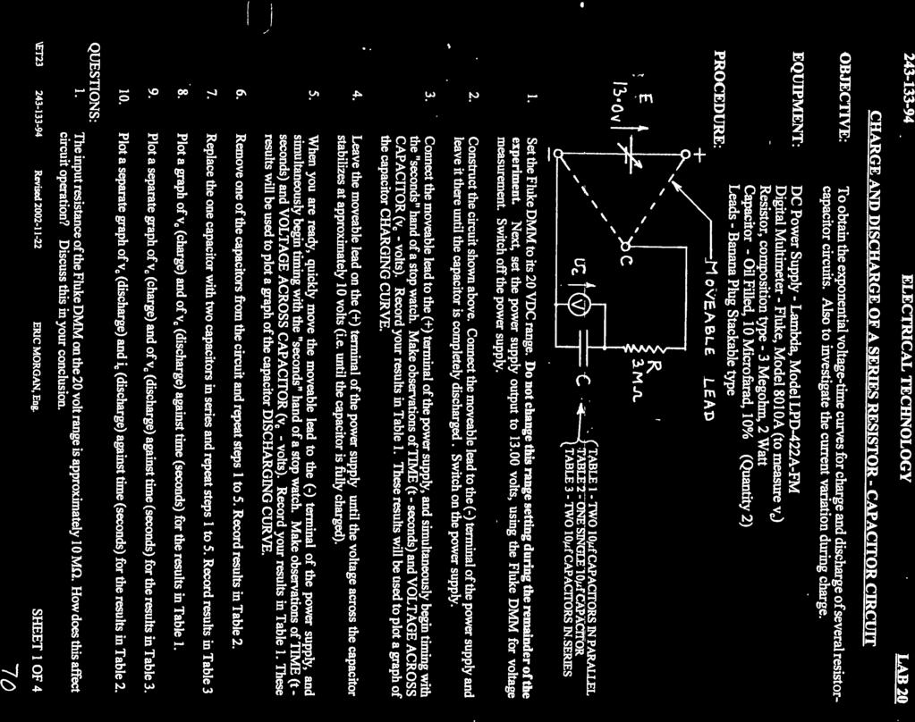


81
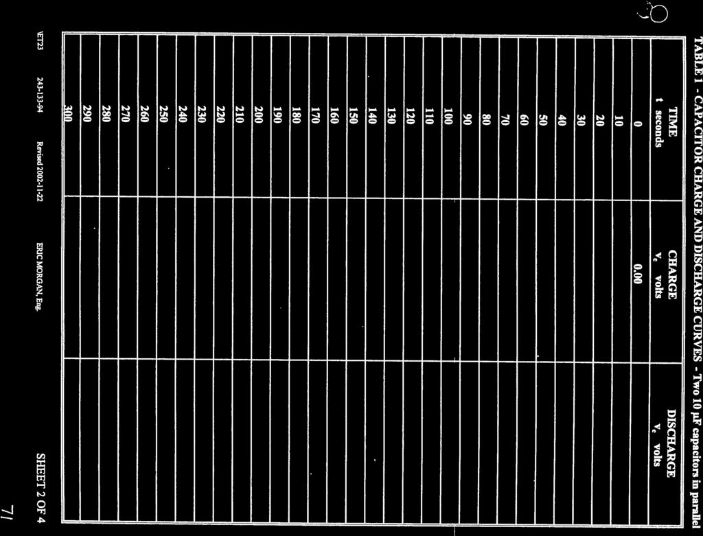

82
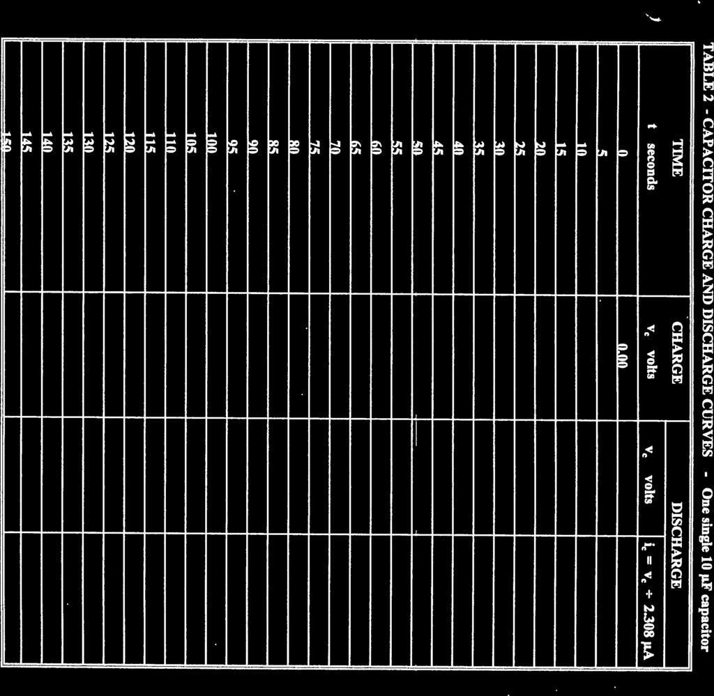
83
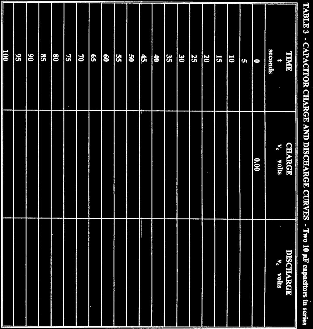
84
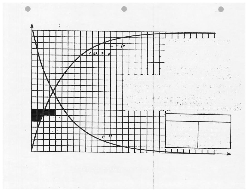
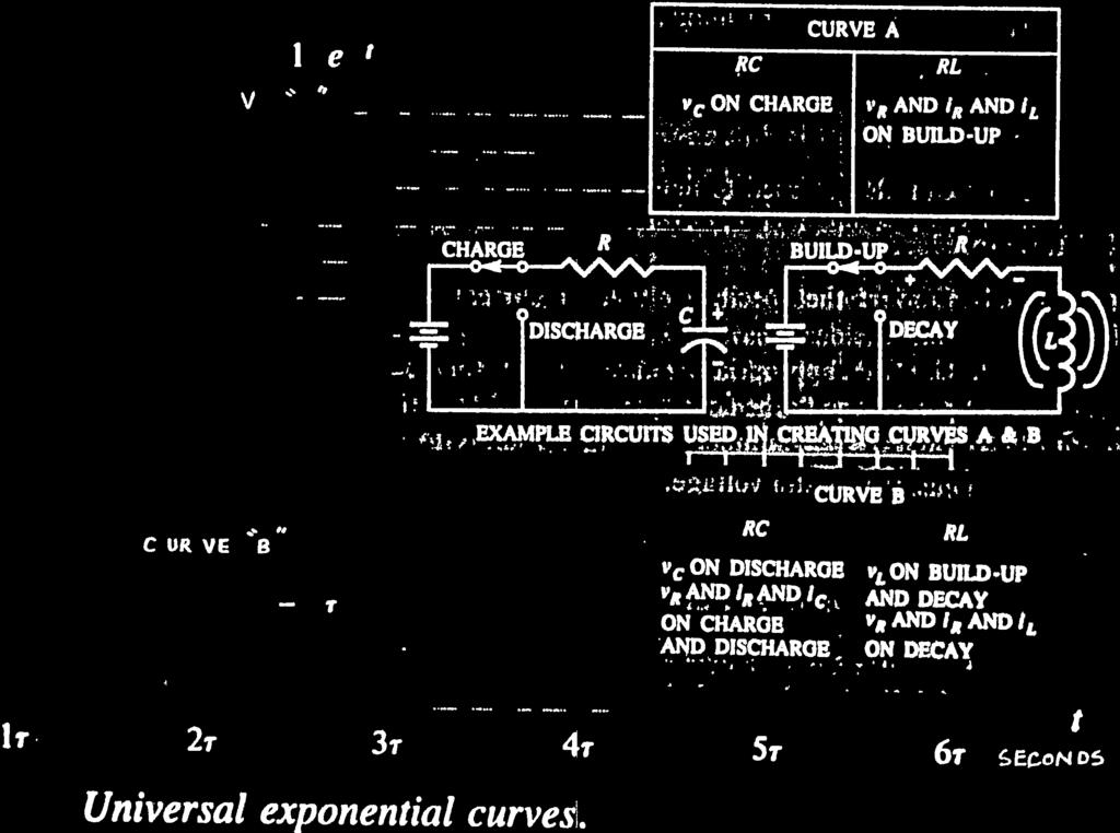


85
UNIVERSITY OF NORTH CAROLINA AT CHARLOTTE Department of Electrical and Computer Engineering
 UNIVERSITY OF NORTH CAROLINA AT CHARLOTTE Department of Electrical and Computer Engineering EXPERIMENT 2 BASIC CIRCUIT ELEMENTS OBJECTIVES The purpose of this experiment is to familiarize the student with
ECE ECE285. Electric Circuit Analysis I. Spring Nathalia Peixoto. Rev.2.0: Rev Electric Circuits I
 ECE285 Electric Circuit Analysis I Spring 2014 Nathalia Peixoto Rev.2.0: 140124. Rev 2.1. 140813 1 Lab reports Background: these 9 experiments are designed as simple building blocks (like Legos) and students
ECE 2006 University of Minnesota Duluth Lab 11. AC Circuits
 1. Objective AC Circuits In this lab, the student will study sinusoidal voltages and currents in order to understand frequency, period, effective value, instantaneous power and average power. Also, the
Laboratory 2 (drawn from lab text by Alciatore)
") Laboratory 2 (drawn from lab text by Alciatore) Instrument Familiarization and Basic Electrical Relations Required Components: 2 1k resistors 2 1M resistors 1 2k resistor Objectives This exercise is designed
Laboratory 2 (drawn from lab text by Alciatore) Instrument Familiarization and Basic Electrical Relations Required Components: 2 1k resistors 2 1M resistors 1 2k resistor Objectives This exercise is designed
ECE 53A: Fundamentals of Electrical Engineering I
 ECE 53A: Fundamentals of Electrical Engineering I Laboratory Assignment #1: Instrument Operation, Basic Resistor Measurements and Kirchhoff s Laws Fall 2007 General Guidelines: - Record data and observations
Lab #5 ENG RC Circuits
 Name:. Lab #5 ENG 220-001 Date: Learning objectives of this experiment is that students will be able to: Measure the effects of frequency upon an RC circuit Calculate and understand circuit current, impedance,
University of Jordan School of Engineering Electrical Engineering Department. EE 219 Electrical Circuits Lab
 University of Jordan School of Engineering Electrical Engineering Department EE 219 Electrical Circuits Lab EXPERIMENT 4 TRANSIENT ANALYSIS Prepared by: Dr. Mohammed Hawa EXPERIMENT 4 TRANSIENT ANALYSIS
EET140/3 ELECTRIC CIRCUIT I
 SCHOOL OF ELECTRICAL SYSTEM ENGINEERING UNIVERSITI MALAYSIA PERLIS EET140/3 ELECTRIC CIRCUIT I MODULE 1 PART I: INTRODUCTION TO BASIC LABORATORY EQUIPMENT PART II: OHM S LAW PART III: SERIES PARALEL CIRCUIT
PHYS 235: Homework Problems
 PHYS 235: Homework Problems 1. The illustration is a facsimile of an oscilloscope screen like the ones you use in lab. sinusoidal signal from your function generator is the input for Channel 1, and your
Chapter 1: DC circuit basics
 Chapter 1: DC circuit basics Overview Electrical circuit design depends first and foremost on understanding the basic quantities used for describing electricity: Voltage, current, and power. In the simplest
Direct Current Circuits
 PC1143 Physics III Direct Current Circuits 1 Objectives Apply Kirchhoff s rules to several circuits, solve for the currents in the circuits and compare the theoretical values predicted by Kirchhoff s rule
AME140 Lab #2 INTRODUCTION TO ELECTRONIC TEST EQUIPMENT AND BASIC ELECTRONICS MEASUREMENTS
 INTRODUCTION TO ELECTRONIC TEST EQUIPMENT AND BASIC ELECTRONICS MEASUREMENTS The purpose of this document is to guide students through a few simple activities to increase familiarity with basic electronics
Chapter 1: DC circuit basics
 Chapter 1: DC circuit basics Overview Electrical circuit design depends first and foremost on understanding the basic quantities used for describing electricity: voltage, current, and power. In the simplest
Lab 1: Basic RL and RC DC Circuits
 Name- Surname: ID: Department: Lab 1: Basic RL and RC DC Circuits Objective In this exercise, the DC steady state response of simple RL and RC circuits is examined. The transient behavior of RC circuits
Unit 3.C Electrical Theory, Circuits Essential Fundamentals of Electrical Theory, Circuits
 Unit 3.C Electrical Theory, Circuits Essential Fundamentals of Electrical Theory, Circuits Early Booklet E.C.: + 1 Unit 3.C Hwk. Pts.: / 36 Unit 3.C Lab Pts.: / 50 Late, Incomplete, No Work, No Units Fees?
ECE103 Spring Homework 1
 ECE103 Spring 2015 Homework 1 Due Tuesday January 29 in class. Show all your work; all problems must be properly solved and assumptions justified. A list of results is NOT acceptable. Solve the homework
PHYSICS 221 LAB #6: CAPACITORS AND AC CIRCUITS
 Name: Partners: PHYSICS 221 LAB #6: CAPACITORS AND AC CIRCUITS The electricity produced for use in homes and industry is made by rotating coils of wire in a magnetic field, which results in alternating
PHYS102 Previous Exam Problems. Circuits
 PHYS102 Previous Exam Problems CHAPTER 27 Circuits Combination of resistors Potential differences Single loop circuits Kirchhoff laws Multiloop circuits RC circuits General 1. Figure 1 shows two resistors
Experiment 3. Ohm s Law. Become familiar with the use of a digital voltmeter and a digital ammeter to measure DC voltage and current.
 Experiment 3 Ohm s Law 3.1 Objectives Become familiar with the use of a digital voltmeter and a digital ammeter to measure DC voltage and current. Construct a circuit using resistors, wires and a breadboard
Laboratory 2. Lab 2. Instrument Familiarization and Basic Electrical Relations. Required Components: 2 1k resistors 2 1M resistors 1 2k resistor
 Laboratory 2 nstrument Familiarization and Basic Electrical Relations Required Components: 2 1k resistors 2 1M resistors 1 2k resistor 2.1 Objectives This exercise is designed to acquaint you with the
Experiment 2. Ohm s Law. Become familiar with the use of a digital voltmeter and a digital ammeter to measure DC voltage and current.
 Experiment 2 Ohm s Law 2.1 Objectives Become familiar with the use of a digital voltmeter and a digital ammeter to measure DC voltage and current. Construct a circuit using resistors, wires and a breadboard
Instructions for the final examination:
 School of Information, Computer and Communication Technology Sirindhorn International Institute of Technology Thammasat University Practice Problems for the Final Examination COURSE : ECS304 Basic Electrical
ENGR 1181 Lab 3: Circuits
 ENGR 1181 Lab 3: Circuits - - Lab Procedure - Report Guidelines 2 Overview of Circuits Lab: The Circuits Lab introduces basic concepts of electric circuits such as series and parallel circuit, used in
AC CURRENTS, VOLTAGES, FILTERS, and RESONANCE
 July 22, 2008 AC Currents, Voltages, Filters, Resonance 1 Name Date Partners AC CURRENTS, VOLTAGES, FILTERS, and RESONANCE V(volts) t(s) OBJECTIVES To understand the meanings of amplitude, frequency, phase,
UNIVERSITY OF TECHNOLOGY, JAMAICA SCHOOL OF ENGENEERING. Electrical Engineering Science. Laboratory Manual
 UNIVERSITY OF TECHNOLOGY, JAMAICA SCHOOL OF ENGENEERING Electrical Engineering Science Laboratory Manual Table of Contents Experiment #1 OHM S LAW... 3 Experiment # 2 SERIES AND PARALLEL CIRCUITS... 8
Laboratory Exercise 6 THE OSCILLOSCOPE
 Introduction Laboratory Exercise 6 THE OSCILLOSCOPE The aim of this exercise is to introduce you to the oscilloscope (often just called a scope), the most versatile and ubiquitous laboratory measuring
COURSE OUTLINE. School of Engineering Technology and Applied Science
 COURSE OUTLINE SCHOOL: School of Engineering Technology and Applied Science DEPARTMENT: Information and Communication Engineering Technology (ICET) PROGRAM: Electronics Engineering Technician & Technology
In this section you will learn about Ohm's Law as applied to a single resistor circuit. Phillips Textbook pp including some maths on notation.
 Ohms Law (these theory notes support the ppt) In this section you will learn about Ohm's Law as applied to a single resistor circuit. Phillips Textbook pp. 43-59 including some maths on notation. At the
Sept 13 Pre-lab due Sept 12; Lab memo due Sept 19 at the START of lab time, 1:10pm
 Sept 13 Pre-lab due Sept 12; Lab memo due Sept 19 at the START of lab time, 1:10pm EGR 220: Engineering Circuit Theory Lab 1: Introduction to Laboratory Equipment Pre-lab Read through the entire lab handout
UNIVERSITY OF TECHNOLOGY, JAMAICA School of Engineering -
 UNIVERSITY OF TECHNOLOGY, JAMAICA School of Engineering - Electrical Engineering Science Laboratory Manual Table of Contents Safety Rules and Operating Procedures... 3 Troubleshooting Hints... 4 Experiment
DC and AC Circuits. Objective. Theory. 1. Direct Current (DC) R-C Circuit
 R-C Circuit") [International Campus Lab] Objective Determine the behavior of resistors, capacitors, and inductors in DC and AC circuits. Theory ----------------------------- Reference -------------------------- Young
[International Campus Lab] Objective Determine the behavior of resistors, capacitors, and inductors in DC and AC circuits. Theory ----------------------------- Reference -------------------------- Young
2.0 AC CIRCUITS 2.1 AC VOLTAGE AND CURRENT CALCULATIONS. ECE 4501 Power Systems Laboratory Manual Rev OBJECTIVE
 2.0 AC CIRCUITS 2.1 AC VOLTAGE AND CURRENT CALCULATIONS 2.1.1 OBJECTIVE To study sinusoidal voltages and currents in order to understand frequency, period, effective value, instantaneous power and average
Electricity Basics
 Western Technical College 31660310 Electricity Basics Course Outcome Summary Course Information Description Career Cluster Instructional Level Total Credits 4.00 Total Hours 144.00 DC/AC electrical theory
CURRENT ELECTRICITY. 1. The S.I. unit of power is (a) Henry (b) coulomb (c) watt (d) watt-hour Ans: c
 Henry (b) coulomb (c) watt (d) watt-hour Ans: c") CURRENT ELECTRICITY 1. The S.I. unit of power is (a) Henry (b) coulomb (c) watt (d) watt-hour 2. Electric pressure is also called (a) resistance (b) power (c) voltage (d) energy 3. The substances which
CURRENT ELECTRICITY 1. The S.I. unit of power is (a) Henry (b) coulomb (c) watt (d) watt-hour 2. Electric pressure is also called (a) resistance (b) power (c) voltage (d) energy 3. The substances which
RLC Frequency Response
 1. Introduction RLC Frequency Response The student will analyze the frequency response of an RLC circuit excited by a sinusoid. Amplitude and phase shift of circuit components will be analyzed at different
Electrical Engineering Fundamentals
 Electrical Engineering Fundamentals EE-238 Sheet 1 Series Circuits 1- For the circuits shown below, the total resistance is specified. Find the unknown resistance and the current for each circuit. 12.6
DC CIRCUITS AND OHM'S LAW
 July 15, 2008 DC Circuits and Ohm s Law 1 Name Date Partners DC CIRCUITS AND OHM'S LAW AMPS - VOLTS OBJECTIVES OVERVIEW To learn to apply the concept of potential difference (voltage) to explain the action
18-3 Circuit Analogies, and Kirchoff s Rules
 18-3 Circuit Analogies, and Kirchoff s Rules Analogies can help us to understand circuits, because an analogous system helps us build a model of the system we are interested in. For instance, there are
Resistive Circuits. Lab 2: Resistive Circuits ELECTRICAL ENGINEERING 42/43/100 INTRODUCTION TO MICROELECTRONIC CIRCUITS
 NAME: NAME: SID: SID: STATION NUMBER: LAB SECTION: Resistive Circuits Pre-Lab: /46 Lab: /54 Total: /100 Lab 2: Resistive Circuits ELECTRICAL ENGINEERING 42/43/100 INTRODUCTION TO MICROELECTRONIC CIRCUITS
DC Circuits and Ohm s Law
 DC Circuits and Ohm s Law INTRODUCTION During the nineteenth century so many advances were made in understanding the electrical nature of matter that it has been called the age of electricity. One such
VISUAL PHYSICS ONLINE. Experiment PA41A ELECTRIC CIRCUITS
 VISUAL PHYSICS ONLINE Experiment PA41A ELECTRIC CIRCUITS Equipment (see Appendices) 12V DC power supply (battery): multimeter (and/or milliammeter and voltmeter); electrical leads; alligator clips; fixed
Ohm's Law and DC Circuits
 Physics Lab II Ohm s Law Name: Partner: Partner: Partner: Ohm's Law and DC Circuits EQUIPMENT NEEDED: Circuits Experiment Board Two Dcell Batteries Wire leads Multimeter 100, 330, 560, 1k, 10k, 100k, 220k
DC Circuits and Ohm s Law
 DC Circuits and Ohm s Law INTRODUCTION During the nineteenth century so many advances were made in understanding the electrical nature of matter that it has been called the age of electricity. One such
V (in volts) = voltage applied to the circuit, I (in amperes) = current flowing in the circuit, R (in ohms) = resistance of the circuit.
 = voltage applied to the circuit, I (in amperes) = current flowing in the circuit, R (in ohms) = resistance of the circuit.") OHM S LW OBJECTIES: PRT : 1) Become familiar with the use of ammeters and voltmeters to measure DC voltage and current. 2) Learn to use wires and a breadboard to build circuits from a circuit diagram.
OHM S LW OBJECTIES: PRT : 1) Become familiar with the use of ammeters and voltmeters to measure DC voltage and current. 2) Learn to use wires and a breadboard to build circuits from a circuit diagram.
Lab 1: Basic Lab Equipment and Measurements
 Abstract: Lab 1: Basic Lab Equipment and Measurements This lab exercise introduces the basic measurement instruments that will be used throughout the course. These instruments include multimeters, oscilloscopes,
Lab 8 - INTRODUCTION TO AC CURRENTS AND VOLTAGES
 08-1 Name Date Partners ab 8 - INTRODUCTION TO AC CURRENTS AND VOTAGES OBJECTIVES To understand the meanings of amplitude, frequency, phase, reactance, and impedance in AC circuits. To observe the behavior
REQUIRED SKILLS AND KNOWLEDGE UEENEEE104A. Topic and Description NIDA Lesson CARD #
 REQUIRED SKILLS AND KNOWLEDGE UEENEEE104A KS01-EE104A Direct current circuits T1 Topic and Description NIDA Lesson CARD # Basic electrical concepts encompassing: electrotechnology industry static and current
Lab Exercise # 9 Operational Amplifier Circuits
 Objectives: THEORY Lab Exercise # 9 Operational Amplifier Circuits 1. To understand how to use multiple power supplies in a circuit. 2. To understand the distinction between signals and power. 3. To understand
Electrical and Electronic Principles in Engineering
 Unit 56: Electrical and Electronic Principles in Engineering Level: 3 Unit type: Optional Assessment type: Internal Guided learning: 60 Unit introduction The modern world relies on electrical and electronic
DC Circuits, Ohm's Law and Multimeters Physics 246
 DC Circuits, Ohm's Law and Multimeters Physics 246 Theory: In this lab we will learn the use of multimeters, verify Ohm s law, and study series and parallel combinations of resistors and capacitors. For
Group: Names: Resistor Band Colors Measured Value ( ) R 1 : 1k R 2 : 1k R 3 : 2k R 4 : 1M R 5 : 1M
 R 1 : 1k R 2 : 1k R 3 : 2k R 4 : 1M R 5 : 1M") 2.4 Laboratory Procedure / Summary Sheet Group: Names: (1) Select five separate resistors whose nominal values are listed below. Record the band colors for each resistor in the table below. Then connect
2.4 Laboratory Procedure / Summary Sheet Group: Names: (1) Select five separate resistors whose nominal values are listed below. Record the band colors for each resistor in the table below. Then connect
Lightbulbs and Dimmer Switches: DC Circuits
 Introduction It is truly amazing how much we rely on electricity, and especially on devices operated off of DC current. Your PDA, cell phone, laptop computer and calculator are all examples of DC electronics.
University of Portland EE 271 Electrical Circuits Laboratory. Experiment: Inductors
 University of Portland EE 271 Electrical Circuits Laboratory Experiment: Inductors I. Objective The objective of this experiment is to verify the relationship between voltage and current in an inductor,
Note: 1. All the students must strictly follow all the safety precautions. 2. In case of any question or concern, please contact LAB INSTRUCTOR or TA.
 UNIVERSITY OF WATERLOO ELECTRICAL & COMPUTER ENGINEERING DEPARTMENT FALL 2006 E&CE 261: Energy Systems and Components EXPERIMENT 1: THREE-PHASE SYSTEMS Contents covered in this laboratory exercise: 1.
OPERATIONAL AMPLIFIERS (OP-AMPS) II
 II") OPERATIONAL AMPLIFIERS (OP-AMPS) II LAB 5 INTRO: INTRODUCTION TO INVERTING AMPLIFIERS AND OTHER OP-AMP CIRCUITS GOALS In this lab, you will characterize the gain and frequency dependence of inverting op-amp
OPERATIONAL AMPLIFIERS (OP-AMPS) II LAB 5 INTRO: INTRODUCTION TO INVERTING AMPLIFIERS AND OTHER OP-AMP CIRCUITS GOALS In this lab, you will characterize the gain and frequency dependence of inverting op-amp
1 V = IR P = IV R eq. 1 R i. = R i. = R eq. V = Energy Q. I = Q t
 Chapters 34 & 35: Electric Circuits NAME: Text: Chapter 34 Chapter 35 Think and Explain: 1-3, 6-8, 10 Think and Explain: 1-10 Think and Solve: 1-6 Think and Solve: 1-4 Vocabulary: Ohm s Law, resistance,
Voltage, Current and Resistance
 Voltage, Current and Resistance Foundations in Engineering WV Curriculum, 2002 Foundations in Engineering Content Standards and Objectives 2436.8.3 Explain the relationship between current, voltage, and
HANDS-ON ACTIVITY 4 BUILDING SERIES AND PARALLEL CIRCUITS BACKGROUND WIRING DIRECTIONS
 ACTIVITY 4 BUILDING SERIES AND PARALLEL CIRCUITS BACKGROUND Make sure you read the background in Activity 3 before doing this activity. WIRING DIRECTIONS Materials per group of two: one or two D-cells
Electrical Measurements
 Electrical Measurements INTRODUCTION In this section, electrical measurements will be discussed. This will be done by using simple experiments that introduce a DC power supply, a multimeter, and a simplified
RESISTANCE & OHM S LAW (PART I
 RESISTANCE & OHM S LAW (PART I and II) Objectives: To understand the relationship between potential and current in a resistor and to verify Ohm s Law. To understand the relationship between potential and
CHAPTER 9. Sinusoidal Steady-State Analysis
 CHAPTER 9 Sinusoidal Steady-State Analysis 9.1 The Sinusoidal Source A sinusoidal voltage source (independent or dependent) produces a voltage that varies sinusoidally with time. A sinusoidal current source
VCE VET INTEGRATED TECHNOLOGIES
 Victorian Certificate of Education 2015 SUPERVISOR TO ATTACH PROCESSING LABEL HERE Letter STUDENT NUMBER VCE VET INTEGRATED TECHNOLOGIES Written examination Monday 9 November 2015 Reading time: 9.00 am
ET1210: Module 5 Inductance and Resonance
 Part 1 Inductors Theory: When current flows through a coil of wire, a magnetic field is created around the wire. This electromagnetic field accompanies any moving electric charge and is proportional to
PH213 Chapter 26 solutions
 PH213 Chapter 26 solutions 26.6. IDENTIFY: The potential drop is the same across the resistors in parallel, and the current into the parallel combination is the same as the current through the 45.0-Ω resistor.
Wallace Hall Academy Physics Department. Electricity. Pupil Notes Name:
 Wallace Hall Academy Physics Department Electricity Pupil Notes Name: 1 Learning intentions for this unit? Be able to state that there are two types of charge; positive and negative Be able to state that
LAB 1: Familiarity with Laboratory Equipment (_/10)
") LAB 1: Familiarity with Laboratory Equipment (_/10) PURPOSE o gain familiarity with basic laboratory equipment oscilloscope, oscillator, multimeter and electronic components. EQUIPMEN (i) Oscilloscope
LAB 1: Familiarity with Laboratory Equipment (_/10) PURPOSE o gain familiarity with basic laboratory equipment oscilloscope, oscillator, multimeter and electronic components. EQUIPMEN (i) Oscilloscope
Physics 120 Lab 1 (2018) - Instruments and DC Circuits
 - Instruments and DC Circuits") Physics 120 Lab 1 (2018) - Instruments and DC Circuits Welcome to the first laboratory exercise in Physics 120. Your state-of-the art equipment includes: Digital oscilloscope w/usb output for SCREENSHOTS.
Physics 120 Lab 1 (2018) - Instruments and DC Circuits Welcome to the first laboratory exercise in Physics 120. Your state-of-the art equipment includes: Digital oscilloscope w/usb output for SCREENSHOTS.
Q3.: When switch S is open, the ammeter in the circuit shown in Fig 2 reads 2.0 A. When S is closed, the ammeter reading: (Ans: increases)
") Old Exams-Chapter 27 T081 Q1. Fig 1 shows two resistors 3.0 Ω and 1.5 Ω connected in parallel and the combination is connected in series to a 4.0 Ω resistor and a 10 V emf device. The potential difference
Old Exams-Chapter 27 T081 Q1. Fig 1 shows two resistors 3.0 Ω and 1.5 Ω connected in parallel and the combination is connected in series to a 4.0 Ω resistor and a 10 V emf device. The potential difference
ELECTRICAL CIRCUITS LABORATORY MANUAL (II SEMESTER)
") ELECTRICAL CIRCUITS LABORATORY MANUAL (II SEMESTER) LIST OF EXPERIMENTS. Verification of Ohm s laws and Kirchhoff s laws. 2. Verification of Thevenin s and Norton s Theorem. 3. Verification of Superposition
ELECTRICAL CIRCUITS LABORATORY MANUAL (II SEMESTER) LIST OF EXPERIMENTS. Verification of Ohm s laws and Kirchhoff s laws. 2. Verification of Thevenin s and Norton s Theorem. 3. Verification of Superposition
Unit 3. Electrical Circuits
 Strand G. Electricity Unit 3. Electrical Circuits Contents Page Representing Direct Current Circuits 2 Rules for Series Circuits 5 Rules for Parallel Circuits 9 Circuit Calculations 14 G.3.1. Representing
EE 233 Circuit Theory Lab 3: First-Order Filters
 EE 233 Circuit Theory Lab 3: First-Order Filters Table of Contents 1 Introduction... 1 2 Precautions... 1 3 Prelab Exercises... 2 3.1 Inverting Amplifier... 3 3.2 Non-Inverting Amplifier... 4 3.3 Integrating
University of Pennsylvania Department of Electrical and Systems Engineering. ESE 206: Electrical Circuits and Systems II - Lab
 University of Pennsylvania Department of Electrical and Systems Engineering ESE 206: Electrical Circuits and Systems II - Lab AC POWER ANALYSIS AND DESIGN I. Purpose and Equipment: Provide experimental
UNIVERSITY OF UTAH ELECTRICAL ENGINEERING DEPARTMENT
 UNIVERSITY OF UTAH ELECTRICAL ENGINEERING DEPARTMENT ECE 3110 LAB EXPERIMENT NO. 4 CLASS AB POWER OUTPUT STAGE Objective: In this laboratory exercise you will build and characterize a class AB power output
Questions Bank of Electrical Circuits
 Questions Bank of Electrical Circuits 1. If a 100 resistor and a 60 XL are in series with a 115V applied voltage, what is the circuit impedance? 2. A 50 XC and a 60 resistance are in series across a 110V
University of Jordan School of Engineering Electrical Engineering Department. EE 219 Electrical Circuits Lab
 University of Jordan School of Engineering Electrical Engineering Department EE 219 Electrical Circuits Lab EXPERIMENT 7 RESONANCE Prepared by: Dr. Mohammed Hawa EXPERIMENT 7 RESONANCE OBJECTIVE This experiment
ECE 2274 Lab 2. Your calculator will have a setting that will automatically generate the correct format.
 ECE 2274 Lab 2 Forward (DO NOT TURN IN) You are expected to use engineering exponents for all answers (p,n,µ,m, N/A, k, M, G) and to give each with a precision between one and three leading digits and
Electric Circuits Vocabulary
 Electric Circuits Vocabulary Term Electric Current Definition Electric Circuit Open Circuit Conductors Insulators Ohm s Law Current Voltage Resistance Electrical Power Series Circuit Parallel Circuit Page
Table of Contents. Introduction...2 Conductors and Insulators...3 Current, Voltage, and Resistance...6
 Table of Contents Introduction...2 Conductors and Insulators...3 Current, Voltage, and Resistance...6 Ohm s Law... 11 DC Circuits... 13 Magnetism...20 Alternating Current...23 Inductance and Capacitance...30
Lab 3: AC Low pass filters (version 1.3)
") Lab 3: AC Low pass filters (version 1.3) WARNING: Use electrical test equipment with care! Always double-check connections before applying power. Look for short circuits, which can quickly destroy expensive
Lab 3: AC Low pass filters (version 1.3) WARNING: Use electrical test equipment with care! Always double-check connections before applying power. Look for short circuits, which can quickly destroy expensive
Network Analysis I Laboratory EECS 70LA
 Network Analysis I Laboratory EECS 70LA Spring 2018 Edition Written by: Franco De Flaviis, P. Burke Table of Contents Page no. Foreword...3 Summary...4 Report Guidelines and Grading Policy...5 Introduction
ECE 2274 Lab 2 (Network Theorems)
") ECE 2274 Lab 2 (Network Theorems) Forward (DO NOT TURN IN) You are expected to use engineering exponents for all answers (p,n,µ,m, N/A, k, M, G) and to give each with a precision between one and three
ECE 2274 Lab 2 (Network Theorems) Forward (DO NOT TURN IN) You are expected to use engineering exponents for all answers (p,n,µ,m, N/A, k, M, G) and to give each with a precision between one and three
Chapter 12 Electric Circuits
 Conceptual Physics/ PEP Name: Date: Chapter 12 Electric Circuits Section Review 12.1 1. List one way electric current is similar to water current and one way it is different. 2. Draw a circuit diagram
Homework Assignment 01
 Homework Assignment 01 In this homework set students review some basic circuit analysis techniques, as well as review how to analyze ideal op-amp circuits. Numerical answers must be supplied using engineering
Lab 4 OHM S LAW AND KIRCHHOFF S CIRCUIT RULES
 57 Name Date Partners Lab 4 OHM S LAW AND KIRCHHOFF S CIRCUIT RULES AMPS - VOLTS OBJECTIVES To learn to apply the concept of potential difference (voltage) to explain the action of a battery in a circuit.
University of North Carolina-Charlotte Department of Electrical and Computer Engineering ECGR 3157 Electrical Engineering Design II Fall 2013
 Exercise 1: PWM Modulator University of North Carolina-Charlotte Department of Electrical and Computer Engineering ECGR 3157 Electrical Engineering Design II Fall 2013 Lab 3: Power-System Components and
Lab 9 - INTRODUCTION TO AC CURRENTS AND VOLTAGES
 145 Name Date Partners Lab 9 INTRODUCTION TO AC CURRENTS AND VOLTAGES V(volts) t(s) OBJECTIVES To learn the meanings of peak voltage and frequency for AC signals. To observe the behavior of resistors in
Lab #2: Electrical Measurements II AC Circuits and Capacitors, Inductors, Oscillators and Filters
 Lab #2: Electrical Measurements II AC Circuits and Capacitors, Inductors, Oscillators and Filters Goal: In circuits with a time-varying voltage, the relationship between current and voltage is more complicated
Introduction to Electronic Equipment
 Introduction to Electronic Equipment INTRODUCTION This semester you will be exploring electricity and magnetism. In order to make your time in here more instructive we ve designed this laboratory exercise
ELEG 205 Analog Circuits Laboratory Manual Fall 2017
 ELEG 205 Analog Circuits Laboratory Manual Fall 2017 University of Delaware Dr. Mark Mirotznik Kaleb Burd Aric Lu Patrick Nicholson Colby Banbury Table of Contents Policies Policy Page 3 Labs Lab 1: Intro
Circuit Analysis Laboratory Workbook
 Circuit Analysis Laboratory Workbook Synthesis Lectures on Electrical Engineering Editor Richard C. Dorf, University of California, Davis Circuit Analysis Laboratory Workbook Teri L. Piatt and Kyle E.
The Discussion of this exercise covers the following points:
 Exercise 5 Resistance and Ohm s Law EXERCISE OBJECTIVE When you have completed this exercise, you will be familiar with the notion of resistance, and know how to measure this parameter using an ohmmeter.
Duration of resource: 23 Minutes. Year of Production: Stock code: VEA12041
 ADDITIONAL RESOURCES We use electrical circuits every day. In the home, the car, at work and school they are a vital part of our lives. This program covers the basics of electrical circuits in detail.
Electromagnetism Unit- Current Sub-Unit
 4.2.1 Electrical Current Definitions current unit: or requires: Example #3 A wire carries a current of 50 amperes. How much charge flows through the wire in 10 seconds? How many electrons pass through
University of Jordan School of Engineering Electrical Engineering Department. EE 204 Electrical Engineering Lab
 University of Jordan School of Engineering Electrical Engineering Department EE 204 Electrical Engineering Lab EXPERIMENT 1 MEASUREMENT DEVICES Prepared by: Prof. Mohammed Hawa EXPERIMENT 1 MEASUREMENT
Lab 4: Analysis of the Stereo Amplifier
 ECE 212 Spring 2010 Circuit Analysis II Names: Lab 4: Analysis of the Stereo Amplifier Objectives In this lab exercise you will use the power supply to power the stereo amplifier built in the previous
KINGS COLLEGE OF ENGINEERING DEPARTMENT OF ELECTRICAL AND ELECTRONICS ENGINEERING QUESTION BANK UNIT I BASIC CIRCUITS ANALYSIS PART A (2-MARKS)
") KINGS COLLEGE OF ENGINEERING DEPARTMENT OF ELECTRICAL AND ELECTRONICS ENGINEERING QUESTION BANK YEAR / SEM : I / II SUBJECT CODE & NAME : EE 1151 CIRCUIT THEORY UNIT I BASIC CIRCUITS ANALYSIS PART A (2-MARKS)
KINGS COLLEGE OF ENGINEERING DEPARTMENT OF ELECTRICAL AND ELECTRONICS ENGINEERING QUESTION BANK YEAR / SEM : I / II SUBJECT CODE & NAME : EE 1151 CIRCUIT THEORY UNIT I BASIC CIRCUITS ANALYSIS PART A (2-MARKS)
In-Class Exercises for Lab 2: Input and Output Impedance
 In-Class Exercises for Lab 2: Input and Output Impedance. What is the output resistance of the output device below? Suppose that you want to select an input device with which to measure the voltage produced
Physics 201 Laboratory: Analog and Digital Electronics. I-0. Introductory Notes
 Physics 201 Laboratory: Analog and Digital Electronics -0. ntroductory Notes Definitions of circuit and current. Current is the flow of charge. We may think of electrons flowing through a wire as a current
Regents Physics Mr. Mellon Based on Chapter 22 and 23
 Name Regents Physics Mr. Mellon Based on Chapter 22 and 23 Essential Questions What is current? How is it measured? What are the relationships for Ohm s Law? What device measures current and how is it
ELECTRIC CIRCUITS CMPE 253 DEPARTMENT OF COMPUTER ENGINEERING LABORATORY MANUAL ISHIK UNIVERSITY
 ELECTRIC CIRCUITS CMPE 253 DEPARTMENT OF COMPUTER ENGINEERING LABORATORY MANUAL ISHIK UNIVERSITY 2017-2018 1 WEEK EXPERIMENT TITLE NUMBER OF EXPERIMENT No Meeting Instructional Objective 2 Tutorial 1 3