GRT Autopilot Installation, Setup & Testing
|
|
|
- Ashley Richard
- 5 years ago
- Views:
Transcription

1 GRT Autopilot Installation, Setup & Testing Revision B 18-July-2018
2 Supplement Revision Notes Revision Date Change Description A Friday November B 07/18/18 Complete revision. Supersedes April dated Section 5, Flight Testing and Fine Tuning the Autopilot, updated to allow better adjustment of gains, especially roll and pitch servo gains to improve autopilot performance in all conditions. 2 Revision B
3 Table of Contents Section 1: Introduction 1.1 About the GRT Autopilot GRT Autopilot Limitations.. 4 Section 2: Servo Installation 2.1 GRT Servo Mount Kits General Servo Hardware & Mounting Guidelines 6 Section 3: Wiring Considerations 3.1 Wiring Overview & Options Serial Port Assignment. 15 Section 4: Programming & Calibration 4.1 Initial Display Unit Configuration ARINC 429 OBS Settings Autopilot Calibration Required Safety Checks Before First Flight 22 Section 5: Flight Testing and Fine-Tuning the Autopilot 5.1 Adjusting Servo Gains,,,,,,,,,,,, Autopilot Flight Testing Procedures Servo Torque Settings Autopilot Troubleshooting Guide 33 Section 6: Autopilot Servo Maintenance 6.1 Servo Software Updates Continuing Airworthiness/Inspections. 35 Diagrams Autopilot Servo Wiring- Single Display Unit 16 Autopilot Servo Wiring- Dual Display Units. 17 Servo Drawing Revision B
4 Autopilot Installation, Setup & Testing Section 1: Introduction 1.1 About the GRT Autopilot The GRT Autopilot provides full autopilot functionality in both roll and pitch for all phases of flight, including coupling to lateral and vertical navigation sources. The GRT autopilot sotware is standard equipment in the Horizon HX and HXr. The Sport comes standard with full lateral autopilot and altitude hold; Vertical navigation is a software option. The autopilot includes many safety features, including the ability to override the servo by applying force to the control stick at any time. Safety features are also built into the servos to prevent them from jamming the flight controls in the rare case of a mechanical failure of the servo. This manual is intended for use with the GRT autopilot and GRT servos. Other autopilots may or may not have the same capabilities as the GRT autopilot, and may not perform as expected. If you are using a third-party autopilot with your GRT EFIS system, please refer to all applicable documentation from the autopilot manufacturer for proper installation, setup, checkout and in-flight procedures. WARNING: The flight control system is one of the most critical systems of the airplane. Failure of the flight controls is likely to result in death. Appropriate attention must be paid to ensure the servo installation does not adversely affect the integrity of the flight controls. 1.2 GRT Autopilot Limitations Engaging the autopilot with a roll angle exceeding 10 degrees will cause the autopilot to first roll wings level before entering the Heading Hold mode. The autopilot cannot control altitude or vertical speed when the roll angle exceeds 65 degrees. If the autopilot is engaged with a roll angle exceeding 65 degrees, the pitch control will be suspended (the pitch servo will not be engaged) until the airplane has rolled to less than 60 degrees of bank. If the autopilot is operating and the bank angle exceeds 65 degrees, the autopilot will suspend pitch control and disengage the pitch servo. When the bank angle is reduced to less than 60 degrees of bank, it will resume normal operation. While the pitch function is suspended due to excessive bank angle, the EFIS will show the pitch autopilot mode as "SUSP. Revision B 4


5 Section 2: Servo Installation 2.1 GRT Servo Mount Kits GRT supplies mounting kits for several types of kitplanes, as well as a universal mount that can be adapted to almost any type of airplane. We encourage the installer to consult with us, as well as the aircraft designer, and any other expert that is appropriate, to evaluate the safety of all servo installations. Use of a GRT mounting kit and following this manual and other GRT documentation does not ensure that the servo installation is safe. There are many variables, various and possible unknown versions of each type aircraft that may or may not be known to us, as well as alterations that may be made to an aircraft by the builder, or installation variations or errors that we can not be aware of that can adversely affect the safety of the installation. This manual covers the general installation guidelines for a pitch and roll servo using GRT servo mount kits in a typical 2-place homebuilt experimental aircraft. It should be used as a general guide; your aircraft and servo installation will likely be different in some ways. However, the servo geometry and over-center information in Section 2.2 must be followed in all servo installations, regardless of aircraft type. 5 Revision B

6 2.2 General Servo Hardware & Mounting Guidelines GRT s servos were designed as a drop-in hardware replacement for TruTrak and Dynon servos, making hardware upgrades easy for people with older autopilot systems who wish to retrofit their aircraft with a GRT system. However, our servos are digital, so the wiring configuration of other brands of autopilots will not work with GRT servos. GRT servos require fewer wires than analog servos. The servos are designed to push and pull on the control surface bellcrank, or in some cases, directly on the pushrod. Moving the control stick while handflying will also move the servo, but the leverage of the control stick combined with internal electronic drag reduction in the stepper motor makes servo drag virtually unnoticeable. A specially-machined brass shear screw holds the servo arm rigid to the motor shaft. Without it, the servo arm turns freely on the shaft. This shear pin is critical to the safety of the aircraft- If the servo motor ever seizes, the pilot can break the shear pin and regain mechanical control of the aircraft without relying on any type of electronic clutch override. Shear Screw WARNING! The shear pin is specially-designed piece of safety equipment. NEVER replace the shear pin with any other type of hardware! The ability to easily break the shear pin is critical to pilot safety in the event of servo failure. Servo Mounting Kit Details While we make several mounting kits for different airplanes, all of them have the same basic components: Aluminum mounting bracket for the servo Aluminum control rod to run from the servo to the aileron or elevator bellcrank/pushrod Rod end bearings with washers to connect the control rod on each end AN hardware to fasten everything together The biggest difference between the kits is the method of mounting the aluminum servo bracket to the airframe and the length of the control rod. For example, the pitch servo mounting bracket for the composite Arion Lightning is screwed to a pair of included phenolic feet that are then epoxied to the inside of the fiberglass fuselage. The Van s RV-6 roll servo bracket is riveted directly to the metal belly skin of the aircraft, so its shape is different from other RV models in which the roll servo is attached to a wing rib. See the photos on the next page. 6 Revision B


7 Universal servo mount bracket (left). Composite aircraft use the same bracket with the addition of phenolic feet, which are epoxied to the airframe (right). Van s RV-6 roll servo bracket is shaped differently, with the main structural face of the bracket to be riveted to the aircraft s belly skin. 7 Revision B


8 L-bracket Spacer Van s RV-8 roll servo installation inside the wing. Note the L-bracket used to support the aft side of the servo. The L bracket, spacer and black powdercoated bellcrank/servo support bracket are supplied in the GRT RV-8 roll servo mount kit. Servo/Bellcrank Mount Bracket replaces the original Van s bellcrank mount. 8 Revision B


9 Control rod approximately parallel to main elevator pushrod Spacer for proper control rod geometry Friction clamp assembly holds servo control rod firmly to main elevator pushrod Composite mounting blocks Side view of pushrod clamp Composite Arion Lightning kitplane/lsa pitch servo installation detail. The universal aluminum servo mounting tray is mounted to composite blocks which are then epoxied to the aircraft belly skin. The servo is mounted behind the baggage area. The friction clamp assembly and composite mounting feet are included with the GRT pitch servo installation kit for Arion Lightning. Upper view of pushrod clamp 9 Revision B
10 Servo Mounting Guidelines The following guidelines should always be used when mounting GRT servos. Inventory the Servo Mount Kit If you purchased a GRT mount kit, it has an inventory sheet. Check to make sure all of the parts and hardware listed are included in the kit. If anything is missing or if you have any questions, please give us a call. Servo Location Things to consider when deciding where to put the servos are: Clearance of the moving parts from all wiring, hardware, and structural components to allow full range of controls with no chance of binding, rubbing or tangling. The servos must be mounted as rigidly as possible. Certain mounting surfaces, such as wing ribs, may flex under load and can potentially cause an over-center control arm condition, which will lead to a potentially fatal condition of jamming or reversing the controls. Consider this when you choose the location for your servos and reinforce wing ribs or other flexible surfaces as necessary. Adequate space surrounding the servos to minimize the chance of overheating don t stuff them inside a tiny enclosed space if you can help it. Ease of access for installation, testing and maintenance. Remember that shear screws occasionally break due to excess stress on the controls, so easy servo access on remote FBO ramps may come in handy on a long cross-country journey. (And remember to keep a spare shear screw or two in your tool kit.) Attaching the Servo to the Aluminum Mount Bracket The servo mounting bracket comes in several different shapes optimized for different aircraft designs, materials and recommended servo locations. Use the four AN3H-6A bolts and star washers to attach the servo frame to the aluminum mounting bracket included in the kit. Run safety wire between each pair of bolts as shown here to prevent the bolts from backing out of the pre-tapped holes in the servo body and potentially jamming the servo and controls. Safety Wire 10 Revision B
11 Attaching the Control Rod to the Servo Arm Use standard procedure for attaching the rod end bearings to the control rod and servo arm. The following diagram illustrates accepted practice. The large area washer on the side opposite from the servo arm will prevent the control rod from falling off if the bearing fails. Servo Arm MM-3 rod end bearing AN3H-7A bolt AN A Nylon insert locknut AN flat washer (2) AN970-3 Large Area Washer AN315-4R Jam Nut Control Rod Control Binding or Over-center Motion Movement of the flight controls must not result in any binding. The servo arms must never move more than 60 degrees from the neutral position, or no less than 30 degrees of rotation away from an over-center condition. This must be verified by moving the aileron and elevator to all possible positions, including full up and right, full up and left, full down and right, full down and left, and all other positions. Take servo mount flexibility into consideration as well. Failure to comply with this requirement can result in locked flight controls, which if were to occur in flight, would result in certain death. Servo Arm Centerline Servo Range Limit Danger Zone Servo Range Limit Control Rod Danger Zone Over-Center Condition 11 Revision B
12 Servo-Control Surface Geometry It is important to understand how the servos should work with the control surfaces for optimal control throw and to prevent over-center operation, which could lead to seizure of the flight controls. To get maximum servo control throw, two things must be set properly: 1. The control rod must be perpendicular to the servo arm centerline when the servo arm is in the neutral position. 2. When the servo arm is centered within its range of motion, the control surface must also be centered within its range of motion. Servo Arm Centerline 90 Control Rod 25 Up 15 Down Control Throw Centerline 5 difference Neutral Aileron Position When a control surface does not have symmetrical opposite deflections, the center of the control surface range of motion is not the same as the neutral position. In the example below, the aileron has a max deflection up of 25 and a max deflection down of 15 for built-in aileron differential. When the control rod is at the proper length, the aileron will actually be at the 5 up position when the servo arm is centered within its range of motion. To figure this mathematically: 25 up+ 15 down = 40 total deflection 40 total / 2 = 20 of deflection on each side of the control throw centerline 25 up - 20 = 5 of up aileron at the center of the range of motion During installation, check the control surface deflection when the servo is neutralized. If necessary, lengthen or shorten the control rod until the control surface is at the proper deflection. 12 Revision B
13 Control Surface Throw and Mechanical Torque To adjust the control surface range of motion, or throw, sometimes it is necessary to try different holes in the servo control arm. As the control rod connection point moves further from the servo shaft, the amount of leverage the servo has on the control surface decreases, therefore its mechanical torque decreases. Servos are normally connected in the holes that provide a proper amount of control surface throw. Servo torque can be electronically adjusted during flight testing. Max throw / Min torque Servo control rod Min throw / Max torque Servo shaft/arm pivot point On the other end of the control rod, the opposite is true. The further the servo control rod is from the pivot point of the bellcrank, the servo s leverage on the control surface increases; therefore, torque increases and throw decreases. To control surface Min throw / Max torque Max throw / Min torque Servo control rod Bellcrank pivot point Main pushrod- To control stick WARNING: Immediately after changing connection points in either the servo arm or the control surface attach point, push the control surface firmly from stop to stop and measure the servo arm deflection to make sure it cannot move to within 30 degrees of running over-center. See Page 11 of this manual for the over-center condition diagram. 13 Revision B
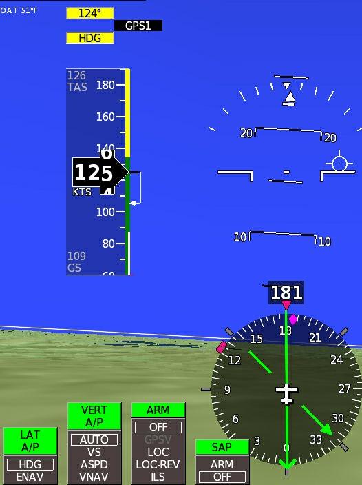
14 Section 3: Wiring Considerations 3.1 Wiring Overview and Options The wiring of the GRT autopilot servos requires several external switches, including a servo power switch, an engage/disengage momentary pushbutton, and an optional disengage-only momentary pushbutton. The switch functions are as follows: Servo Power Switch (required) This switch provides electrical power to the servo(s). Normally, power is turned on just after takeoff, and turned off just before landing. The autopilot will not engage when this switch is turned on. The autopilot will only engage if the servos are powered and the EFIS commands it to engage. The power switch is also an important safety feature, as removing power from the servos will always disengage them and return full control of the airplane to the pilot. Future versions of the EFIS software may provide an option for automatic envelope protection features. This feature would only be functional if the servos are powered. Engage/Disengage Pushbutton (required) This momentary switch commands the autopilot to engage the servo and control the airplane. The first press of this button will engage the autopilot and simultaneously display the autopilot shortcut menu, shown at right. The autopilot will initially enter vertical speed hold and heading hold modes. Selected heading and altitude will not apply. In this mode, the autopilot will simply attempt to hold the current vertical speed and heading indefinitely until the pilot presses one of the softkeys on the autopilot shortcut menu. Pressing this button again will disengage the autopilot and return control of the airplane to the pilot. Option: The airplane may be wired with one "Engage/Disengage" button for each axis, or one button to control both at the same time. Disengage Pushbutton (optional) This momentary switch is wired only to the roll servo, but it disengages both the roll and pitch servos. When this switch is closed for more than 0.5 seconds the autopilot will be disengaged. Often this button is located on the control stick to provide a convenient means of disconnecting the autopilot. Pressing the button for less than 0.5 seconds has no affect. 14 Revision B
15 Autopilot Source Select Switch (optional) The autopilot can only be controlled by one display unit at a time. This switch allows either display unit to control the servos for redundancy in a dual-display system. In single-display or multi-display systems where autopilot redundancy is not critical, this switch can be omitted. 3.2 Serial Port Assignment The servos utilize multiplex serial control, which allows them both to be controlled by one set of EFIS serial ports. The serial connections for the servos are spliced together, and from there, a single wire runs to each EFIS serial port. Pitch Roll IN OUT IN OUT IN OUT Display Unit Start your wiring installation by deciding which serial port you will use for your servos. You may fill in the My System table below to record the serial ports, pins and wire colors to aid in creating your wiring diagram or schematic for your airplane. Refer to the Connector Definitions on the GRT Avionics website or the pinout diagram in the Appendix of the EFIS installation manual to find pin assignments for the serial ports. Refer to the appropriate wiring diagram, either single-display or dual/multi-display, on the following pages to wire the rest of the servo connections. Wire the servos to the display units and switches using standard aircraft wiring practices. My System- Servo Wiring Information Display Unit 1 Serial Port Display Unit Pin Wire Color Notes IN OUT Display Unit 2 Serial Port Display Unit Pin Wire Color Notes IN OUT 15 Revision B
16 16 Revision B
17 17 Revision B
18 Section 4: Programming & Calibration 4.1 Initial Display Unit Configuration Follow the table below to configure each display unit wired to the servos. It s probably easiest to configure both display units at the same time. Be sure to SAVE SETTINGS before exiting or switching to a different Set Menu page. Press NEXT or MORE (HXr) until you see the Set Menu softkey label. Press the Set Menu softkey. Turn the right knob to highlight the General Setup page and press the knob to access it. NOTE: All gains should be set to 100% to start. Set Menu Page Setting Value General Setup Serial Port Rate* 9600 General Setup Serial Port Input* GRT Autopilot Servo General Setup Serial Port Output* GRT Autopilot Servo General Setup Lateral Autopilot Functions On if roll servo is installed General Setup Vertical Autopilot Functions On if pitch servo is installed General Setup Turn Anticipation Range Set maximum range in nm from the active waypoint to allow an early turn (Internal flight plans only) General Setup Autopilot Serial Output Normal General Setup Autopilot Control Profile Auto General Setup Pitch Activity 100% (does not apply to GRT servos) A/P Maintenance Bank Angle Limit A/P Maintenance Envelope Min/Max A/P Maintenance Engage Switch Configuration Set max bank angle for autopilot turns Enter minimum and maximum indicated airspeed values for autopilot operation Select the switch configuration for the aircraft: Separate Roll and Pitch (2 switches) OR Single Roll and Pitch (1 switch) * Fill in blank with display unit serial port you designated for the servos. 18 Revision B

 Customize your autopilot with 2 values for each of the following: Climb IAS Climb VS Descent IAS Descent VS Set a gentle cruise climb/descent and a more aggressive rate for each. 1.")
19 Set the Autopilot Climb/Descent Presets The GRT autopilot offers pilots a variety of present climb & descent rates and airspeeds. These presets cut down on pilot workload by providing single-touch controls for the most common speeds and rates. To utilize the preset features, program the EFIS for your particular airplane and flying style. (NOTE: Sport users without the Vertical Commands software option can skip this step.) Customize your autopilot with 2 values for each of the following: Climb IAS Climb VS Descent IAS Descent VS Set a gentle cruise climb/descent and a more aggressive rate for each. 1. Press MORE > Set Menu > Primary Flight Display 2. Scroll to Climb IAS Preset #1 and begin entering speed/rate settings appropriate for your aircraft. SAVE your settings. 4.2 ARINC 429 OBS Settings These General Setup menu settings affect how the EFIS communicates with IFR NAV/GPS receivers. While they are not direct autopilot settings, they do affect how the autopilot navigates, so they are presented here for convenience. General Setup > ARINC: Send Selected Course No - The NAV/GPS unit uses its own OBS setting and does not take the OBS command from the EFIS. In flight, the OBS on the EFIS and the OBS on the receiver must be set separately. Yes (Default)- The EFIS always sends its OBS selection to the NAV/GPS unit. In flight, set the OBS on the EFIS and it carries across to the NAV/GPS receiver every time, no matter which NAV source is selected. Works well for Garmin GNS 430/530 and GTN 650/750-type systems with complete ARINC wiring. GPS only - Always sends the GPS course on the EFIS to the NAV/GPS unit, but never sends VHF NAV OBS settings to the NAV/GPS unit. This works best for a GPS-only unit. When Selected - Only sends the selected OBS course when one of the modes of the NAV/GPS receiver is selected on the EFIS. This will allow an analog OBS resolver or a built-in OBS to be used on the NAV/GPS unit while another navigation source is used and controlled by the EFIS. 19 Revision B
20 General Setup > ARINC: Sel Crs Mode Filter On (Default)- If the EFIS receives mode information from the NAV/GPS unit, it will send the selected course related to the mode selected on the GPS/NAV. If the EFIS does not receive mode information from the NAV/GPS unit, the behavior is the same as Off. OFF- The EFIS sends the selected course for the current mode selected in the EFIS, ignoring the current mode of the GPS/NAV. Only select OFF if the EFIS is getting the NAV/GPS mode mixed up. 4.3 Autopilot Calibration 1. Press MORE or NEXT to access the Set Menu pages. Scroll to and select A/P Maintenance. 2. Turn on power to the servos using the Servo Power switch. 3. Check for servo communication. See that the "Roll Software Version" and "Pitch Software Version" are not grayed-out, and a software version is indicated for each servo. If these are not observed, check power and serial connections to the servo. 4. Set the Roll and Pitch Torque to the highest setting for now. Upon the completion of flight testing the torque may be lowered to make it easier to override the autopilot, but for testing the highest torque level reduces the chance of limited servo authority from mis-interpreting the autopilot s response. Servo Calibration & Direction Checks 5. Select the "Roll Servo Direction" setting and press the knob. Select "YES" in response to the "Run Servo Direction Test?" The roll servo should move. 6. Allow the servo to move until the aileron reaches its stops. For most airplanes, it will be necessary to manually assist the servo in reaching the stop by applying pressure to the control stick. Verify that any flex in the servo mounting does not allow the servo arm mover further and come anywhere close to an over-center condition. (Do this for both directions for both servos.) 7. Using the diagrams in Section 2 of this manual, verify proper servo movement and control deflection. Again, verify the servo arm should never approach an over-center condition when the servo is at the limit of its travel. Verify also that the mounting of the servo is rigid such that its mount does not bend, or deflect in such a way that the servo can move its output arm after the aileron linkage has reached its stop. 8. Press the REVERSE softkey and repeat steps 5-7 for the other direction. 9. Before exiting this test, press the REVERSE soft key as necessary to set the correct servo direction according to the directions on the display unit screen. Press CONFIRM when complete. 20 Revision B


21 10. Repeat steps 5-9 for the pitch servo. Switch Communication 1. Verify the operation of the engage/disengage momentary switch(es) by observing the E/D Button Status counter(s). If No Communication is listed, check for bad connections in the switch wiring. 2. If the optional Disengage switch is connected, verify its operation by observing the Disengage/CWS Button Status counter. If No Communication is listed, check for bad connections in the switch wiring. 3. If the sensed pitch torque/trim changes when a switch is pressed, the switch has been erroneously wired to the pitch servo Pin 7, which must be left unconnected. (The pitch servo automatically disengages through the multiplex serial control when the roll servo is disengaged.) Pitch Trim Torque Sensor Calibration The GRT pitch servo includes internal torque sensing. This allows the EFIS to provide trim advisories to allow the pilot to trim the airplane to keep the stick forces within the servo s limits of authority. Trimming is usually necessary when the flap position changes, and periodically as fuel burn shifts the center-of-gravity. Pitch trim advisories appear above the altimeter tape only when action is required. The higher the number, the higher the torque imbalance. The arrow points in the direction of the required trim adjustment. Green arrows represent a mild trim adjustment, while yellow/red arrows represent large trim adjustments that can break a shear pin or damage the servo if not remedied immediately. Before engaging the autopilot it is good practice to trim the airplane to remove stick forces (as you would if hand flying). In some airplanes where sufficient lost travel exists in the pitch linkage, slightly mis-trimming the airplane can reduce slight pitch oscillations induced by this lost motion. The following procedure will calibrate the torque sensor of the pitch servo as it is installed in the aircraft and allow the autopilot to display an accurate PITCH UP or PITCH DOWN annunciation on the EFIS (shown at right). NOTE: This calibration must be repeated if the servo torque setting is changed. 1. Press MORE or NEXT > Set Menu > A/P Maintenance. Scroll to and select Pitch Trim Calibration. This page displays a value that represents the torque being sensed by the servo. It also shows 21 Revision B
22 the minimum and maximum values sensed. These values are reset each time this page is viewed. 2. Be sure the the Pitch Servo Torque to set to the maximum (15). (If the servo torque settings have already been intentionally reduced, necessitating repeating this procedure, then do not alter the torque setting. 3. Press the START CAL softkey. 4. Apply a very slight back pressure to the control stick. increase the back pressure applied until the servo slips. This will be felt as a sudden thump in the stick. 5. Repeat step 4 several times until the minimum/maximum no longer changes. 6. Repeat steps 4 and 5, this time applying forward pressure. 7. When the test is complete, press the "Store Trim Cal" softkey. 4.4 Required Safety Checks Before First Flight The following checks are critical to the safe operation of the GRT autopilot installation. Servo Linkage & Control Throw: Visually inspect the servo installation to confirm the proper control throws as described in Section 2 of this manual. Control Stops Properly Installed: The aircraft flight control system must include control stops to ensure the range of motion of the flight controls is known and mechanically limited. Verify the flight control stops are installed, are functional, and are robust. If a flight control stop was to fail, the range of motion may allow the servo linkage to enter an over-center condition that would result in locked flight controls. servos may not be mounted in aircraft that are not equipped with control stops. Other Servo & Hardware Concerns: r Verify the servo is securely mounted and all mounting hardware has been safety-wired, properly torqued, uses castled nuts with cotter pins, or uses self-locking hardware as is appropriate. r The total amount of slop (also called lost motion or dead band ) in the controls, from the control surface through all linkages to the servo arm, should be minimized. Excessive slop can result in degraded autopilot performance. Any hardware associated with the flight controls that are altered to accept the servo installation must be replaced with similar hardware that includes the same type of locking for the nut. 22 Revision B
23 r Rod ends must include large washers through the mounting bolts, such that if the rod end was to fail by the bearing separating from the rod end housing, the rod end housing is retained by the large washer so that the pushrod can not become loose in the airplane. r The rod ends have the minimum number of threads in the pushrods and they have been secured with jam nuts. r Wiring to the servo is secured so that it can not interfere with the flight controls and does not touch any moving parts. 23 Revision B
24 r Airflow around the servo is not restricted to allow convection around the servo to allow it to cool. If the servo is allowed to get too hot, the torque it can supply will be limited. Section 5: Flight-Testing and Fine-Tuning the Autopilot 5.1 Adjusting Servo Gains Flight testing is required to adjust the servo and autopilot gain settings for optimal autopilot response. Gain settings may vary with individual aircraft. When the gains are properly set for your aircraft, you will enjoy the full precision of the GRT autopilot, including: Minimal oscillations in pitch and roll. Smooth and Rapid acquisition of selected targets such as heading, altitude, GPS course, localizer, etc. Comfortable ride quality in turbulence. The first two characteristics are trade-offs. If the gain is set very low, the autopilot will have a slow, deliberate response, without oscillations, but the acquisition of the selected targets will be slow. Conversely, a high gain will acquire targets quickly, but with oscillations and overshoots. When the gain settings are adjusted properly, the autopilot provides a comfortable ride in turbulence, while still accurately controlling the airplane. If a gain is too high, it will feel as if turbulence is amplified by the autopilot. If a gain is too low, the airplane will be slow to respond to turbulence and will not hold an altitude or vertical speed or track a GPS course or heading as accurately as it otherwise could Roll and Pitch Servo Gains must be adjusted first. Servo gains affect ride quality, especially in turbulence, and how quickly and accurately the autopilot is to reach a target, such as a selected altitude, heading or GPS course. The roll and pitch gains are adjusted individually, and do not interact with each other. Before performing these adjustments, we highly recommend you read these instructions carefully on the ground, and understand them well enough that you have them committed to memory. It is also recommended to have a check pilot with you to watch for traffic while performing these tests. The servo gains are best adjusted when the flying in smooth air, at the normal cruise speed and altitude. Roll servo gain, roll damping gain, pitch servo gain, and pitch damping gain should be set to no higher than 100% to start the test. 24 Revision B
25 Overview of Procedure for adjusting the Servo Gains The goal of this procedure is to adjust the servo gain as high as possible without any roll or pitch oscillations being present. The servo damping is adjusted as necessary to allow higher and higher servo gains to be set without oscillation. The Servo Response Test page is used to evaluate these settings because it commands a zero roll and pitch attitude. This removes any effect from the outer loop control laws, such as the altitude hold, heading hold, etc, making it easier to evaluate the servo gain and damping settings. Step-by-Step Procedure for adjusting the Servo Gains Caution: During this test the autopilot will cause rolling (or pitching) that can increase without bound. Be ready to hold the stick to stop this, or disengage the autopilot with the engage/disengage button, exiting the Servo Response Test page, or by turning off servo power. 1. Verify Servo directions are set (Servo Direction will not show NOT SET ), and Roll and Pitch Torque are set to the maximum (15). 2. Adjust pitch trim so that very slight forward stick pressure is required to hold the nose level. If you have roll trim, adjust it so that there are minimal roll stick forces. 3. Select the Servo Response Test page from the Set Menu, A/P Maintenance page. 4. With the airplane in level flight, press the Start softkey. This will command the autopilot to hold zero roll and pitch and will engage the autopilot. Exiting the Servo Roll Response Test will disengage the autopilot. 5. If the autopilot begins rolling left and right (roll oscillations), the starting gains are too high and must be reduced before proceeding further. 6. If not already selected, select the Servo Response Test page from the Set Menu, A/P Maintenance page. With the airplane in level flight, press the Start softkey. This will command the autopilot to hold zero roll and pitch and will engage the autopilot. 7. If no roll oscillations are observed, apply a quick push to the stick in roll to disturb the airplane and observe if this causes continuous (and possibly increasing) roll oscillations to begin. If this does not happen, then exit the Servo Response Test page, and Increase the Roll Servo Gain, and re-select the Servo Response Test until the airplane just begins to roll back and forth roll continuously (roll oscillations) after this disturbance. 8. Exit the servo response test and increase the Roll Servo Damping, repeat steps 6 and 7, until there are no continuous roll oscillations. The autopilot will appear to be working normally, but more adjustment is required. 25 Revision B

26 9. Write down the Roll Servo Gain and Roll Servo Damping gains. 10. Exit the Servo Response Test, and Increase the Roll Servo Gain to the next higher increment. Repeat steps 6-8 until it is not possible to stop the roll oscillations by changing the Roll Servo Damping. 11. The ideal setting is the highest Roll Servo Gain setting which can be selected that does not oscillate, and the Roll Servo Damping that keeps it from oscillating. 12. Repeat this procedure for the pitch servo, observing the airplane pitch response and adjusting the Pitch Servo Gain and the Pitch Servo Damping, and applying a quick push in pitch on the stick to evaulate pitch response. 13. When flying in turbulence, the autopilot should not add to the turbulence, but should respond in such a way that the ride quality in turbulence is slightly better than hand flying. If the roll or pitch axis feels that the autopilot is adding to the turbulence, then reduce the Roll or Pitch servo gain one step. 5.2 Autopilot Gain Adjustments Refer to the GRT Autopilot User Guide for detailed operation instructions and definitions of the EFIS autopilot annunciations. Follow the general steps in this section to test the various autopilot modes and adjust gain settings as necessary. Before performing these adjustments, be sure the Servo Gains have been adjusted according to the previous section. 26 Revision B
27 WARNING: Always climb to a safe altitude, well away from all terrain and obstacles, preferably in uncontrolled, empty airspace, and slow the aircraft to below V A before engaging the autopilot during testing. Be sure all seatbelts are fastened tightly and loose items in the cockpit are secure. NOTE: Trim the aircraft for straight and level cruise flight and get it to fly as hands-off as possible before engaging the autopilot. Autopilot gains are set at the bottom of the Set Menu, General Setup, settings menu. In many cases, setting all these gains to 100% is sufficient for good autopilot performance. The following procedures can be used to adjust particular modes if necessary. Step 1: Start with all Autopilot gains set to 100%: 1. Save settings, go back to Main Menu page, and select General Setup menu. 2. Set all autopilot gains to 100%. Step 2: Heading Mode Test Heading gain should be set as high as possible without causing excessive roll or heading oscillations. Bank angle is limited by the Maximum Bank Angle setting on the A/P Maintenance set menu page. Note that Roll Gain does not affect heading; only Heading Gain affects the lateral behavior of the autopilot while in HDG Mode. 1. This adjustment is normally made in smooth air at cruise speed. 2. Synch the heading bug with the present heading. 3. Press the autopilot Engage/Disengage button, then press the yellow HDG ALT softkey to engage the autopilot in Heading Mode. 4. Note the aircraft s roll activity while tracking the selected heading. Adjust the heading gain as high as possible without causing roll or heading oscillations. 27 Revision B
 1.")

28 5. Change the selected heading by about degrees and note the activity of the autopilot. If overshoot of the selected heading or roll oscillations are observed, reduce the gain until these are eliminated. Step 3: ENAV Mode Test (Tracking a GPS course) 1. Press the NAV softkey (or OBS on HXr), then press the appropriate GPS softkey to choose the GPS nav source. 2. Enter a direct-to waypoint into the flight plan of the selected GPS and press EXIT to activate it. To reduce the possibility of an abrupt course change when the autopilot is engaged, choose a waypoint straight ahead of you or hand-fly the airplane onto the GPS course before the next step. 3. When you are on the GPS course, press the autopilot Engage/Disengage button, then press the green NAV ALT softkey. This engages the autopilot in ENAV mode tracking the GPS course. 4. Note the amount of aileron activity in straight and level flight while tracking the GPS. Set the Roll Gain as high as possible, but not so high that it results in excess roll activity in smooth air. Some roll oscillations will are normal due to the lost motion (slope) in the linkage between the ailerons and roll servo arm. 5. When the aircraft can track the GPS course smoothly with no excess roll movement, disengage the autopilot. Hand fly to about feet and 20 degrees off course. 6. Press the Engage/Disengage button and press the green NAV/ALT softkey to engage the autopilot in ENAV mode, and observe how aggressively the airplane recaptures the course. It should smoothly fly back onto the GPS course and recapture it with a slight overshoot. If this is not the case, you may need to adjust XT (Cross Track) Gain. For most airplanes, the default setting of 100% will work fine for XT Gain, which affects the tracking of GPS, VOR, Localizer and the lateral portion of Synthetic Approach. If XT Gain is too low, the intercept angle for 28 Revision B
 is acceptable.")

29 all course intercepts will be at shallow angles, and will be sluggish. If too high, a large amount of overshoot will be observed. 7. If undesirable roll oscillations occur when flying in turbulent air, reduce these gains the smallest amount possible until the roll oscillations (ride qualify) is acceptable. Step 4: Altitude Hold Test NOTE: This test should initially be performed in smooth air. After altitude holds can be performed well in calm air, fly the aircraft again in turbulent conditions and repeat this test to fine-tune the autopilot s performance. 1. Fly to a safe altitude and trim the airplane for hands-off level flight at normal cruise speed and altitude. 2. Turn on power to the pitch servo. 3. Press the A/P Engage/Disengage button, followed by the yellow HDG/ALT softkey shown at right to engage the autopilot in Altitude Hold mode. The aircraft will attempt to hold the present altitude and, if the roll servo is turned on, present heading. 4. Pay attention to the quality of the ride as the autopilot attempts to hold altitude: If the airplane seems to chase the altitude and overcontrol the elevator, cut the Altitude Gain in half and try again. If the airplane s altitude wanders and its corrections seem lazy, double the Altitude Gain and try again. NOTE: If you hear or feel bumping in the controls during this test, the autopilot is probably fighting the pitch trim. Adjust trim as indicated in the trim warning indicator shown at right. If this does not smooth out the bumping, disengage a/p to prevent damage to the pitch servo shear pin. Recalibrate the pitch trim sensor as described in Section When the aircraft holds its altitude accurately without pitch oscillations in smooth air, the altitude hold gain is roughly set. Step 5: Vertical Speed Climb & Descent Test NOTE: Like the Altitude Hold test, the VS test should be performed in smooth air initially. After the basic VS climbs and descents can be performed smoothly in calm air, fly the aircraft again in turbulent conditions and repeat this test to fine-tune the autopilot s performance. 29 Revision B
30 Note to Sport EFIS Users: The climb and descent sections of the test profile only apply if your system has the optional Vertical Commands software. 1. Fly to a safe altitude and trim the airplane for hands-off level flight. 2. Synch the heading bug to present heading. 3. Turn on power to the pitch servo. 4. Press the A/P Engage/Disengage button, followed by the yellow HDG/ALT softkey to engage the autopilot in Altitude Hold mode. The aircraft will attempt to hold the present altitude and, if the roll servo is turned on, the heading selected by the heading bug. 5. Press the right knob to access the autopilot mode controls, then press the Vert A/P softkey to highlight VS. This will put all climbs and descents in vertical speed mode. 6. Turn (HXr) or press/turn the right EFIS knob to set a new altitude in the altitude selection box. For ease of evaluation, choose a cardinal VFR altitude at least 1000 feet above present altitude. Press the right knob again to accept the new altitude. The vertical speed select box will appear with large white type in the middle of the PFD as shown below. 7. Press the right knob to accept the climb rate in the box, OR press one of the vertical speed preset softkeys to select a different vertical speed. You may also rotate/press the right knob to manually enter a different climb rate. As soon as the rate is accepted, the aircraft will begin to climb. Add power as necessary to maintain airspeed. 8. Pay attention to the quality of the ride as the autopilot attempts to maintain the selected vertical speed by manipulating the elevator. 9. Repeat Steps 5-7 in a descent. 30 Revision B
31 If the airplane significantly chases the vertical speed, causing oscillations and and over-controlling of the elevator, cut the Vertical Speed Gain in half and try again. If the airplane s vertical speed wanders and its pitch corrections seem lazy, double the Vertical Speed Gain and try again. 10. When the vertical speed gain is set to provide a comfortable climb and descent in calm air, repeat the test in turbulent air. The Vertical Speed Gain is set properly when the airplane can hold its vertical speed without oscillations in turbulence. Step 6: Airspeed Climb & Descent Test Climbs and descents at a selected airspeed testing should be performed only in smooth or nearly smooth air. Due to reduced ride quality compared with the vertical speed climb/descent, this mode is not recommended in moderate or heavier turbulence. Increasing the Airspeed Gain will allow capture of the selected airspeed more quickly. As the gain increases, the tolerance for turbulence may diminish, and pitch oscillations will occur when this gain is too high. When this gain is too low, capture of the selected airspeed will be excessively slow or may not occur. The highest gain without pitch oscillations is recommended. Step 7: VOR, Localizer and Glideslope Tracking Tests After the roll, heading, and vertical speed gains are all set satisfactorily, the next step is adjusting gains for VHF navigation systems. VOR, Localizer and Glideslope signals are all cone-shaped, meaning they get smaller as the aircraft gets closer to the NAVAID station or transmitter antenna. In these cases, the gains should be set so that the aircraft tracks the signal cleanly with no oscillations until it gets close to the transmitter. NOTE: If the autopilot is sluggish or overactive while tracking most of the navigation signals including GPS and Synthetic Approach, the XT (Cross Track) Gain may need to be adjusted. Follow these guidelines when setting the NAVAID gains: VOR Gain: Adjust as high as possible so that oscillations begin when close to the VOR. If tracking of the VOR causes an uncomfortable ride, reduce the gains. VOR signals are prone to electronic noise which can affect the autopilot at higher gain settings. Localizer Gain: Adjust as high as possible without back-and-forth oscillations until feet above the ground on an ILS. Glideslope Gain: Adjust it to stay on the glideslope without oscillations in turbulence. 31 Revision B
32 5.3 Servo Torque Settings Servo Torque (Set Menu > A/P Maintenance) should be adjusted to give the servos enough authority to accurately control the airplane, but not enough authority to overcome the ability of the pilot to override them in an emergency. The vast majority of airplanes are safe to fly with the torque set to the maximum (15). The highest safe setting is recommended, as low torque settings can result in the autopilot not having enough authority to control the airplane. If the EFIS detects that the servo is unable to control the airplane, an Check Trim warning message will be generated. The sensitivity of this message is controlled using the Trim Alarm Slip Sensitivity setting on the A/P Maintenance page. The recommended setting is Low. NOTE: If pitch servo torque settings are changed, be sure to repeat the Pitch Trim Torque Sensor Calibration in Section Revision B
33 5.4 Autopilot Troubleshooting Guide- Common Situations A/P Action Mode Possible Remedy Actions HDG Adjust heading gain down. Slight, even roll oscillations in calm air The airplane turns crisply in one direction, but is slow or does not turn in the other. The pitch servo does not engage on the ground for testing. When I engage the autopilot on the ground for testing, the control stick shoves to one side and will not relax, even when I turn the heading bug. ENAV (GPS) ENAV (VOR/LOC) ENAV (all) or Synthetic Approach but not HDG All Modes All Modes N/A N/A Adjust roll gain down. Adjust VOR and/or LOC gain down. Adjust XT (Cross Track) gain down. Slop or dead spot in control system- check all mechanical connections for tightness. Some slop is unavoidable and will result in small roll and pitch oscillations that should be well below the level that causes ride discomfort. Intentionally slightly mis-trimming the airplane so that the servo does not have to move through the slop can improve this situation, but is not necessary for normal operation. The roll servo arm is not centered within the ailerons range of motion, and one aileron is getting more travel than the other. See Section 2.2, Servo-Control Surface Geometry. The pitch servo cannot engage when there is no airspeed data sensed by the system, which should be the case while sitting still or slowly taxiing on the ground. The autopilot is probably in ENAV mode, which reads GPS track. On the ground, the GPS groundspeed is too low for an accurate track, so the roll control has nothing to follow. 33 Revision B
34 A/P Action Mode Possible Remedy Actions Slight, even pitch oscillations in calm air. ALT Hold Adjust Altitude Hold Gain down. VS climb/ descent ASPD climb/ descent Synthetic Approach VNAV Adjust VS Gain down. Some oscillations are normal, but if it is uncomfortable, adjust Airspeed Gain down. Adjust Altitude Hold Gain down. Adjust Glideslope Gain down. All Modes The trim tab may be floating slightly if it is perfectly in trail with the elevator, causing a slight dead band area. Set the pitch trim for a slight climb instead of perfectly level before engaging the autopilot. This will add a small air load to the trim tab and stabilize the oscillations. Turbulence feels like it is amplified by the autopilot. All Modes Roll and/or pitch Servo Gain and Servo Damping are not adjusted correctly. Turbulence feels like it is amplified by the autopilot. You hear or feel bumping in the control system when the pitch servo is engaged. When the a/p is engaged, the airplane slowly veers off course in one axis. You hear or feel bumping in the controls, especially in turbulence. ALT Hold All Modes All Modes All Modes Adjust Altitude Hold Gain down. The autopilot is probably fighting the pitch trim. Disengage a/p to prevent the pitch servo shear pin from breaking and re-trim for level flight. See Section 4.3, Pitch Trim Sensor Calibration, to recalibrate the pitch trim sensor if necessary. Shear pin is broken. Check the servo of the affected axis and replace shear pin with an identical replacement. NEVER use any other type of hardware in its place! If this happens often, try turning Servo Torque setting down one or two settings (Set Menu > A/P Maintenance). Be aware of pilot or passengers applying pressure to the control stick while A/P is engaged, as this can also put strain on the servos and break shear pins. Servo is slipping because the Servo Torque is set too low. Increase servo torque one or two settings and retest (Set Menu > A/P Maintenance). 34 Revision B
35 Section 6: Autopilot Servo Maintenance 6.1 Servo Software Updates General autopilot control software is periodically updated as part of the display unit software. Occasionally, the servo software is also updated. If this happens, the new software is posted on the GRT website. 1. Go to Software Updates page, and click the Autopilot link to bring up the Autopilot Servo Software page. Save the new servo software file(s) onto your USB thumb drive in the same way as you would save new Display Unit software. 2. Go to the airplane and turn on the display units. Insert the USB drive to the USB port of a display unit that is wired to the GRT autopilot servos. 3. Access the Set Menu and scroll to A/P Maintenance. Press the right knob and the Autopilot Maintenance screen appears. The servos software version is listed near the bottom of the screen. 4. To load the new software, select Roll Software Update or Pitch Software Update and push the knob. Press YES softkey when prompted. The display unit will send the software to the servo processor. Repeat for other servo, if installed. 5. Because this software update affects only the servos, there is no need to repeat the process with the other display units wired to the servos. 6.2 Continuing Airworthiness/Inspections Perform the servo safety inspection in Section 4 of this manual at each annual or any time a servo control linkage has been disconnected. 35 Revision B
Post-Installation Checkout All GRT EFIS Models
 GRT Autopilot Post-Installation Checkout All GRT EFIS Models April 2011 Grand Rapids Technologies, Inc. 3133 Madison Avenue SE Wyoming MI 49548 616-245-7700 www.grtavionics.com Intentionally Left Blank
GRT Autopilot User Guide. All GRT EFIS Systems
 All GRT EFIS Systems Revision A 22-May-2014 Copyright 2014 3133 Madison Ave. SE Wyoming, MI 49548 (616) 245-7700 www.grtavionics.com Revision Notes Revision Date Change Description A 22-May-2014 Complete
SkyView. Autopilot In-Flight Tuning Guide. This product is not approved for installation in type certificated aircraft
 SkyView Autopilot In-Flight Tuning Guide This product is not approved for installation in type certificated aircraft Document 102064-000, Revision B For use with firmware version 10.0 March, 2014 Copyright
Operating Handbook For FD PILOT SERIES AUTOPILOTS
 Operating Handbook For FD PILOT SERIES AUTOPILOTS TRUTRAK FLIGHT SYSTEMS 1500 S. Old Missouri Road Springdale, AR 72764 Ph. 479-751-0250 Fax 479-751-3397 Toll Free: 866-TRUTRAK 866-(878-8725) www.trutrakap.com
Digiflight II SERIES AUTOPILOTS
 Operating Handbook For Digiflight II SERIES AUTOPILOTS TRUTRAK FLIGHT SYSTEMS 1500 S. Old Missouri Road Springdale, AR 72764 Ph. 479-751-0250 Fax 479-751-3397 Toll Free: 866-TRUTRAK 866-(878-8725) www.trutrakap.com
Digiflight II SERIES AUTOPILOTS
 Operating Handbook For Digiflight II SERIES AUTOPILOTS TRUTRAK FLIGHT SYSTEMS 1500 S. Old Missouri Road Springdale, AR 72764 Ph. 479-751-0250 Fax 479-751-3397 Toll Free: 866-TRUTRAK 866-(878-8725) www.trutrakap.com
Autopilot Servo Installation Guide
 Autopilot Servo Installation Guide RV6 Roll This product is not approved for installation in type certificated aircraft Document 101046-001, Revision F January, 2013 Copyright 2009-2013 by Dynon Avionics,
Autopilot Servo Installation Guide
 Autopilot Servo Installation Guide Sonex/Waiex-Roll This product is not approved for installation in type certificated aircraft Document 101866 000, Revision B March, 2013 Copyright 2009-2013 by Dynon
Fokker 50 - Automatic Flight Control System
 GENERAL The Automatic Flight Control System (AFCS) controls the aircraft around the pitch, roll, and yaw axes. The system consists of: Two Flight Directors (FD). Autopilot (AP). Flight Augmentation System
FAA APPROVED AIRPLANE FLIGHT MANUAL SUPPLEMENT FOR. Trio Pro Pilot Autopilot
 Page 1 480 Ruddiman Drive TRIO AP Flight Manual Supplement North Muskegon, MI 49445 L-1006-01 Rev D FOR Trio Pro Pilot Autopilot ON Cessna 172, 175, 177, 180, 182, 185 and Piper PA28 Aircraft Document
Operating Handbook. For. Gemini Autopilot
 Operating Handbook For Gemini Autopilot TRUTRAK FLIGHT SYSTEMS 1488 S. Old Missouri Road Springdale, AR 72764 Ph. 479-751-0250 Fax 479-751-3397 www.trutrakap.com Table of Contents 1. Revisions... 5 2.
MGL Avionics. iefis. Integrated Autopilot. User and installation manual. Manual dated 14 November Page 1
 MGL Avionics iefis Integrated Autopilot User and installation manual Manual dated 14 November 2014 Page 1 Table of Contents General...4 Autopilot abilities...4 External autopilot systems...4 Internal autopilot
A3 Pro INSTRUCTION MANUAL. Oct 25, 2017 Revision IMPORTANT NOTES
 A3 Pro INSTRUCTION MANUAL Oct 25, 2017 Revision IMPORTANT NOTES 1. Radio controlled (R/C) models are not toys! The propellers rotate at high speed and pose potential risk. They may cause severe injury
Table of Contents. Introduction 3. Pictorials of the 40 and 50 Systems 4. List of Applicable Acronyms 6
 Table of Contents Introduction 3 Pictorials of the 40 and 50 Systems 4 List of Applicable Acronyms 6 System 40 Modes of Operation 7 System 40 Functional Preflight Procedures 10 System 40 In Flight Procedures
Operating Handbook. For. Gemini Autopilot
 Operating Handbook For Gemini Autopilot TRUTRAK FLIGHT SYSTEMS 1488 S. Old Missouri Road Springdale, AR 72764 Ph. 479-751-0250 Fax 479-751-3397 www.trutrakap.com Table of Contents 1. Revisions... 5 2.
Dash8-200/300 - Automatic Flight AUTOMATIC FLIGHT CONTROLS AND INDICATORS. Page 1
 AUTOMATIC FLIGHT CONTROLS AND INDICATORS FLIGHT GUIDANCE MODE SELECTORS (alternate action) - Engages flight director modes of operation. - Flight director command bars display lateral and/or vertical guidance
ADI Pilot I & II Series Autopilots
 ADI Pilot I & II Series Autopilots Installation & Users Manual 8300-012 Rev B TRUTRAK FLIGHT SYSTEMS 1500 S. Old Missouri Road Springdale, AR 72764 Ph: 479-751-0250 Fax: 479-751-3397 Toll free: 866-TRUTRAK
STC GROUP LLC 480 RUDDIMAN DRIVE MUSKEGON, MICHIGAN REPORT NO: REV - TRIO AUTO PILOT INSTALLATION INSTRUCTIONS CESSNA MODEL 182
 STC GROUP LLC 480 RUDDIMAN DRIVE MUSKEGON, MICHIGAN 49445 REPORT NO: 1006003 REV - TRIO AUTO PILOT INSTALLATION INSTRUCTIONS CESSNA MODEL 182 DATE: Original Issue 10 July, 2017 WRITTEN BY: Paul Odum APPROVED
Detrum MSR66A Receiver
 Motion RC User Guide for the Detrum MSR66A Receiver Version 1.0 Contents Review the Receiver s Features... 1 Review the Receiver s Ports and Connection Orientation... 2 Bind the Receiver to a Transmitter
Autopilot EFIS/One & EFIS/Lite
 Autopilot EFIS/One & EFIS/Lite Installation Manual 06/15/04 Copyright blue mountain avionics, inc. 2004 1.0C DRAFT Page 1 of 20 Revision History Release History 1.0 Draft Release of Autopilot Install Guide
MGL Avionics EFIS. Integrated Autopilot. User and installation manual. Manual dated 24 May 2010
 MGL Avionics EFIS Integrated Autopilot User and installation manual Manual dated 24 May 2010 This manual supersedes all previous versions and is applicable for current EFIS firmware versions Page 1 Table
Detrum GAVIN-8C Transmitter
 Motion RC Supplemental Guide for the Detrum GAVIN-8C Transmitter Version 1.0 Contents Review the Transmitter s Controls... 1 Review the Home Screen... 2 Power the Transmitter... 3 Calibrate the Transmitter...
STC GROUP LLC 480 RUDDIMAN DRIVE MUSKEGON, MICHIGAN REPORT NO: G REV E TRIO AUTO PILOT INSTALLATION INSTRUCTIONS
 STC GROUP LLC 480 RUDDIMAN DRIVE MUSKEGON, MICHIGAN 49445 REPORT NO: G-1006-51 REV E TRIO AUTO PILOT INSTALLATION INSTRUCTIONS CESSNA MODEL 182 WITH PREVIOUS CESSNA EQUIPPED AUTO PILOT DATE: Original Issue
16. Wing Final Assembly and Installation
 Section Objective: Installation and rigging of ailerons. Pitot tube install, and any other wing related items. Required Parts: Left aileron push rod ALA-0072, Right aileron push rod ALA-0073, Push tube
Installation & User Guide. For. Pictorial Pilot TRUTRAK FLIGHT SYSTEMS
 Installation & User Guide For Pictorial Pilot TRUTRAK FLIGHT SYSTEMS 1500 S. Old Missouri Road Springdale, AR 72764 Ph. 479-751-0250 Fax 479-751-3397 www.trutrakflightsystems.com INSTALLATION MANUAL for
This page is intentionally blank. GARMIN G1000 SYNTHETIC VISION AND PATHWAYS OPTION Rev 1 Page 2 of 27
 This page is intentionally blank. 190-00492-15 Rev 1 Page 2 of 27 Revision Number Page Number(s) LOG OF REVISIONS Description FAA Approved Date of Approval 1 All Initial Release See Page 1 See Page 1 190-00492-15
DigiFlight II Series Autopilots
 Installation Manual For DigiFlight II Series Autopilots TRUTRAK FLIGHT SYSTEMS 1500 S. Old Missouri Road Springdale, AR 72764 Ph: 479-751-0250 Fax: 479-751-3397 Toll free: 866-TRUTRAK 866-(878-8725) www.trutrakap.com
GX Pilot Series Autopilots
 GX Pilot Series Autopilots Installation/User Manual TRUTRAK FLIGHT SYSTEMS 1500 S. Old Missouri Road Springdale, AR 72764 POSTAL SERVICE ADDRESS P.O. Box 189 Springdale, AR 72765-0189 Ph: 479-751-0250
Instrument Flight Procedures - Glass Cockpits
 Instrument Flight Procedures - Glass Cockpits The concepts contained here are general in nature and can be used by all however, they are targeted toward glass cockpits and, more specifically, integrated
STC GROUP LLC 480 RUDDIMAN DRIVE NORTH MUSKEGON, MICHIGAN REPORT NO: REVISION H
 STC GROUP LLC 480 RUDDIMAN DRIVE NORTH MUSKEGON, MICHIGAN 49445-2783 REPORT NO: 1006004 REVISION H TRIO AUTO PILOT PROVISIONS INSTALLATION INSTRUCTIONS 1953 CESSNA 180 THROUGH 1962 180E 1956 CESSNA 182
2000 Tomlynn Street P.O. Box 6861 Richmond, Virginia / FAX 804/ Service Bulletin
 Sequoia Aircraft Corporation 2000 Tomlynn Street P.O. Box 6861 Richmond, Virginia 23230 804/353-1713 FAX 804/359-2618 Service Bulletin Service Bulletin No. 93-1 Subject: Flap Flutter Date: June 24, 1993
Operations Manual. Caution: Preliminary
 Operations Manual Caution: Preliminary This manual is incomplete at this time. Most, but not all of the data within the manual is accurate, although it is all subject to change and may not match the software
(Build Instructions)
") (Build Instructions) Specifications * Wingspan: 58cm * Length: 50cm * Flying Weight: 59 grams * Channels: 3 (Rudder Elevator Throttle) * Suggested Receiver: 4Ch Micro * Motor: 8mm GearDrive * Prop: GWS
(Build Instructions) Specifications * Wingspan: 58cm * Length: 50cm * Flying Weight: 59 grams * Channels: 3 (Rudder Elevator Throttle) * Suggested Receiver: 4Ch Micro * Motor: 8mm GearDrive * Prop: GWS
Pro Pilot Operation and Installation Manual Trio Avionics Corporation
 Pro Pilot Operation and Installation Manual Trio Avionics Corporation Version 3.8 Notice: This manual uses illustrations that generally show the Pro Pilot model that mounts in a standard 3-1/8 round cutout
Dash8 - Q400 - Autoflight
 12.3.1 Introduction The Automatic Flight Control System (AFCS), provides fail-safe operation of flight director guidance, autopilot, yaw damper and automatic pitch trim functions. 12.3.2 General The Automatic
Garmin GNS430/530 Series Equipment Supplement
 Garmin GNS430/530 Series Equipment Supplement 1-Dec-2012 Garmin GNS430/530 Supplement GRT Avionics Table of Contents Section 1: Introduction 1.1 About the GNS430...... 3 1.2 Data Port Requirements.. 3
MGL Avionics Autopilot. Servo. Specifications & Installation Manual. Last Update: 20 October Disclaimer:
 MGL Avionics Autopilot Servo Specifications & Installation Manual Last Update: 20 October 2010 Disclaimer: MGL Avionics should not be held responsible for errors or omissions in this document. Usage of
Elimination of Elevator Bounce
 For the Agilent Archon Autosampler Rework Instructions CAUTION This kit is intended for use by Agilent Service personnel only. Elevator Removal 1 Open top cover. 2 Open front lower door. 3 Remove vial
12. Wings, Flaps, Ailerons and Struts
 12. Wings, Flaps, Ailerons and Struts Fit Aileron Hinges Reference: Drawing 20270K2 Photo 12.1 Parts Required: 2007092 Aileron LS 200809N Aileron RS 2001394 Hinge 3/16 A1 (4) 2001694 Hinge Pin (4) PH0059N
STC GROUP LLC 480 RUDDIMAN DRIVE MUSKEGON, MICHIGAN REPORT NO REVISION D TRIO AUTO PILOT INSTALLATION INSTRUCTIONS
 STC GROUP LLC 480 RUDDIMAN DRIVE MUSKEGON, MICHIGAN 49445 REPORT NO. 1006003 REVISION D TRIO AUTO PILOT INSTALLATION INSTRUCTIONS CESSNA MODEL 182 WITH CESSNA NAVOMATIC EQUIPPED AUTO PILOT DATE: Original
Viewing the Ryca Motors CS-1 Build Video series at youtube.com/rycamotors is highly recommended before beginning the following assembly process.
 RYCA CS-1 ASSEMBLY GUIDE [The CS-1 installation guides should be used as supplements to the videos found on our Youtube Channel. There is no strict order to the build process, but it is highly recommended
GFC 700 Automated Flight Control System
 CIRRUS AIRPLANE MAINTENANCE MANUAL CHAPTER 22-10: GFC 700 AUTOMATED FLIGHT CONTROL SYSTEM GENERAL GFC 700 Automated Flight Control System 22-10: GFC 700 AUTOMATED FLIGHT CONTROL SYSTEM 1. General (See
Pro Pilot Operation Manual Trio Avionics Corporation
 Pro Pilot Operation Manual Trio Avionics Corporation Manual Part Number 13200000 Notice: This manual uses illustrations that generally show the Pro Pilot model that mounts in a standard 3-1/8 round cutout
105" TIGER MOTH ARF INSTRUCTION MANUAL VERSION 1.0
 105" TIGER MOTH ARF INSTRUCTION MANUAL VERSION 1.0 Step 1. Installation of the aileron servos 1) Mount aileron servo to servo mounting blocks with servo s screws. Install servo mounting plate with screws.
AUTOMATIC FLIGHT CONTROL SYSTEM
 TRIDEN AUTOMATIC FLIGHT CONTROL SYSTEM PILOT S OPERATING HANDBOOK 68S1135 Rev B 02-05-03 FACTORY SERVICE CENTERS Century Flight Systems, Inc. has established Factory owned and operated Customer Service
SP-6 magnetometer. User manual. Installation and in-flight calibration
 SP-6 magnetometer User manual Installation and in-flight calibration Note: This manual is applicable for SP-6 systems that contain in-flight calibration firmware released by MGL Avionics around the 15
Installation Guide For Vizion PMA Autopilot
 Installation Guide For Vizion PMA Autopilot RESTRICTION ON USE, DUPLICATION, OR DISCLOSURE OF PROPRIETARY INFORMATION THIS DOCUMENT CONTAINS PROPRIETARY INFORMATION OF TRUTRAK FLIGHT SYSTEMS, INC. AND
Citabria Pro. Aerobatic Parkflyer. by Joel Dirnberger
 Citabria Pro Aerobatic Parkflyer by Joel Dirnberger Revision C: December 21, 2004 Citabria Pro Building Instructions Length: Wingspan: Wing Area: Flying Weight: Wing Loading: Functions: Specifications:
STC GROUP LLC Page Ruddiman Drive PA-28 & PA-32 Trio Pro Pilot Installation Instructions North Muskegon, Michigan 49445
 STC GROUP LLC Page 1 STC GROUP LLC 480 RUDDIMAN DRIVE MUSKEGON, MICHIGAN 49445 DOCUMENT NO: 1028001 REVISION D TRIO PRO PILOT INSTALLATION INSTRUCTIONS PIPER AIRCRAFT CORPORATION PA-28 AND PA-32 DATE:
Rev J Automatic Pitch Trim
 Installation Manual For Automatic Pitch Trim TRUTRAK FLIGHT SYSTEMS 1488 S. Old Missouri Road Springdale, AR 72764 POSTAL SERVICE ADDRESS P.O. Box 189 Springdale AR 72765-0189 Ph: 479-751-0250 Fax: 479-751-3397
RCU-06 USER MANUAL. Introduction
 RCU-06 USER MANUAL Introduction The following manual will show the features and how to use the new antenna electronic controller. As you will see, it is by far the most simple and intuitive controller
The igyro Simplified!
 The igyro Simplified! I have a confession. Frankly, I am an older person. As such, the common wisdom is that I should move slowly, complain a lot and struggle with new technology. Unfortunately, all three
GoPro Hero Camera Mount. Assembly Manual
 GoPro Hero Camera Mount Assembly Manual Introduction Thank you for purchasing the GoPro Hero Camera Mount for Mikrokopter Quad, Hexa and Okto. The Camera Mount is provided as a kit and requires assembly.
REVISION DESCRIPTION:
 14401 Keil Road NE, Aurora, Oregon, USA 97002 PHONE 503-678-6545 FAX 503-678-6560 www.vansaircraft.com info@vansaircraft.com Service Letters and Bulletins: www.vansaircraft.com/public/service.htm REVISION
New functions and changes summary
 New functions and changes summary A comparison of PitLab & Zbig FPV System versions 2.50 and 2.40 Table of Contents New features...2 OSD and autopilot...2 Navigation modes...2 Routes...2 Takeoff...2 Automatic
Page Chg
 Page Chg Cover...0 Page #...2 TOC-1...2 TOC-2..2 1-1 2 1-2.2 1-3.2 1-4...2 1-5...2 1-6. 2 1-7. 2 1-8. 2 1-9. 2 1-10...2 1-11..2 1-12..2 1-13..2 1-14..2 1-15..2 1-16..2 1-17..2 1-18...2 2-1.0 2-2.0 2-3.2
Page Chg
 Page Chg Cover...0 Page #...1 TOC-1...1 TOC-2...1 1-1.1 1-2.0 1-3.1 1-4...1 1-5...1 1-6. 1 1-7. 1 1-8. 1 1-9. 1 1-10...1 1-11..1 1-12..1 1-13..2 1-14..1 1-15..1 1-16..1 1-17..1 1-18..1 2-1.0 2-2.0 Page
EFIS HORIZON SERIES I. User s Guide and Reference Manual. Grand Rapids Technologies, Inc Madison Avenue Wyoming, MI Rev.
 EFIS HORIZON SERIES I User s Guide and Reference Manual Rev. A 12-20-06 Rewritten by Mike Casey February 27, 2007 www.caseyspm.com/rv7a.html Home Phone 303.771.0815 Grand Rapids Technologies, Inc. 3133
SERVICE BULLETIN
 SERVICE BULLETIN 16-03-28 Date Released: May 6, 2016 (Initial Release) June 2, 2016 (Added Note, pg.11) Date Effective: May 6, 2016 Affected Models: Subject: Required Action: All RV-3, 4, 6/6A, 7/7A, 8/8A,
SECTION 2-19 AUTOPILOT
 AIRPLANE SECTION 2-19 Block General...2-19-05...01 Automatic Flight Control System...2-19-05...02 Flight Guidance System...2-19-05...04 Flight Director...2-19-05...04 Autopilot...2-19-05...04 Flight Director
SKID SET INSTALLATION INTERNAL COMPPONENTS AND PAYLOAD WING PACKING AND END PANEL/RIB TABS
 TABLE OF CONTENTS: BMP SCOUT USER GUIDE PROPELLER GUARD ARMS AND RING INSTALLATION GENERAL RADIO AND FAIL SAFE SET UP UNPACKING AND GETTING STARTED PROPELLER RING AND PROPELLER CLEARANCE PROPELLER INSTALLATION
Installing a 3 Indexer: Desktop Tools
 888-680-4466 ShopBotTools.com Installing a 3 Indexer: Desktop Tools built after October, 2012 Copyright 2016 ShopBot Tools, Inc. page 1 Copyright 2016 ShopBot Tools, Inc. page 2 Table of Contents Overview...5
Stream NXT - assembly instructions
 Stream NXT - assembly instructions Recommended settings CG (measured from root leading edge): Speed/launch camber (+down, near the wing root): Cruise camber (+down, near the wing root): Thermal camber
DISCO DICING SAW SOP. April 2014 INTRODUCTION
 DISCO DICING SAW SOP April 2014 INTRODUCTION The DISCO Dicing saw is an essential piece of equipment that allows cleanroom users to divide up their processed wafers into individual chips. The dicing saw
Lumber Smith. Assembly Manual. If you are having problems assembling the saw and need assistance, please contact us at:
 Lumber Smith Assembly Manual If you are having problems assembling the saw and need assistance, please contact us at: 804-577-7398 info@lumbersmith.com 1 Step 1 Safety Carefully read the Owners Manual.
High performance 90mm fiberglass jet
 High performance 90mm fiberglass jet Assembly manual For intermediate and advanced fliers only! Specs Wingspan: 1255mm Fuselage length: 1250mm Flying weight: 2600-3000g Wing area: 22.6 dm² Wing loading:
DigiFlight II Series Autopilots
 DigiFlight II Series Autopilots Installation Manual TRUTRAK FLIGHT SYSTEMS 1500 S. Old Missouri Road Springdale, AR 72764 Ph: 479-751-0250 Fax: 479-751-3397 www.trutrakap.com INSTALLATION MANUAL For DigiFlight
MM540 Installation Instructions IMPORTANT SAFETY INSTRUCTIONS - SAVE THESE INSTRUCTIONS
 MM50 Installation Instructions IMPORTANT SAFETY INSTRUCTIONS - SAVE THESE INSTRUCTIONS Please read this entire manual before you begin. Do not unpack any contents until you verify all requirements on PAGE.
Super Sky Surfer 2000 Assembly Instructions
 Super Sky Surfer 2000 Assembly Instructions Note: Plug and Play version of the Sky Surfer comes with fuselage pre-glued and motor/servos installed. If you wish to route antennas or wires through the tail,
Specifications Wingspan: 43cm Flying Weight: 33 grams (with battery) Channels: 3 Suggested Receiver: 4Ch Micro Motor: 7mm Brushed Geardrive
 Channels: 3 Suggested Receiver: 4Ch Micro Motor: 7mm Brushed Geardrive") Specifications Wingspan: 43cm Flying Weight: 33 grams (with battery) Channels: 3 Suggested Receiver: 4Ch Micro Motor: 7mm Brushed Geardrive Airframe Kit (Included Contents) * Airframe Parts Sheets (Depron)
Specifications Wingspan: 43cm Flying Weight: 33 grams (with battery) Channels: 3 Suggested Receiver: 4Ch Micro Motor: 7mm Brushed Geardrive Airframe Kit (Included Contents) * Airframe Parts Sheets (Depron)
User Manual Version 1.0
 1 Thank you for purchasing our products. The A3 Pro SE controller is the updated version of A3 Pro. After a fully improvement and optimization of hardware and software, we make it lighter, smaller and
Page Chg
 Page Chg Cover...0 Page #...4 TOC-1...3 TOC-2..3 1-1 2 1-2.3 1-3.3 1-4...3 1-5...3 1-6. 3 1-7. 3 1-8. 4 1-9. 4 1-10...3 1-11..4 1-12..4 1-13..3 1-14..3 1-15..3 1-16..3 1-17..3 1-18...3 1-19..3 2-1.0 2-2.0
Installation Instructions
 Installation Instructions 000964 Revision F Installation Instructions for PIRIT Read this manual fully prior to starting installation. Call American eating Customer ervice with any questions. What you
Standard Operating Procedure
 RIT MULTIDISCIPLINARY SENIOR DESIGN 2010 Standard Operating Procedure Baja Water Propulsion Test Stand This SOP specifies how to assemble, use, troubleshoot, and disassemble the water propulsion system
Atomic Mercury Frame Kit Assembly Manual
 Atomic Mercury Frame Kit Assembly Manual Thank you for purchasing the Atomic Aviation Mercury RACEframe! Please read through the entire manual first before beginning assembly of your kit. The order of
Nancy s Knit Knacks LLC 4 Yard Option Upgrade Kit Assembly Instructions and User Manual
 Nancy s Knit Knacks LLC 4 Yard Option Upgrade Kit Assembly Instructions and User Manual Thank you for purchasing our 4 Yard Option (4YO) Upgrade Kit. To install this upgrade you are simply going to assemble
Trimming your Aerobatic Model
 Trimming your Aerobatic Model When we speak of trimming your aerobatic model we re not talking about trimming in the traditional sense of adjusting the control surfaces to maintain level flight. In this
Instruction Manual book
 Instruction Manual book ITEM CODE BH53. SPECIFICATION Wingspan : 1,250mm 49.21 in. Length : 930mm 36.61in. Weight : 1.1kg 2.42 Lbs. Parts listing required (not included). Battery: 3 CELLS-LI-POLY-11.1V-2,500
48 in. X 96 in. 500 Pound Capacity Motorized Overhead Storage Unit Installation Guide [OPTION B] MODEL # PRM4X8 Patent Pending
![48 in. X 96 in. 500 Pound Capacity Motorized Overhead Storage Unit Installation Guide [OPTION B] MODEL # PRM4X8 Patent Pending](/thumbs/81/83353561.jpg "48 in. X 96 in. 500 Pound Capacity Motorized Overhead Storage Unit Installation Guide [OPTION B] MODEL # PRM4X8 Patent Pending") 48 in. X 96 in. 500 Pound Capacity Motorized Overhead Storage Unit Installation Guide [OPTION B] MODEL # PRM4X8 Patent Pending 1 Table of Contents Table of Contents PAGES Installation Support 3 Safety
48 in. X 96 in. 500 Pound Capacity Motorized Overhead Storage Unit Installation Guide [OPTION B] MODEL # PRM4X8 Patent Pending 1 Table of Contents Table of Contents PAGES Installation Support 3 Safety
Z-Truck Up-and-Down Motion. Y-Truck Side-to-Side Motion. Head. Squaring Plate. Sliding Plate FIGURE 1: THE CARVEWRIGHT MACHINE
 Setup and use of CarveWright CO2 Powered Dragster Jig The CO 2 powered Dragster Jig will arrive from the factory fully assembled, calibrated, and squared. In order to get the best results, your CarveWright
Installing the Hughes BGAN Remote Antenna
 Installing the Hughes BGAN Remote Antenna Product description BGAN Remote Antenna The Hughes BGAN Remote Antenna (HNS Part No. 9501286-0001) is designed to be permanently installed with the Basic Fixed
Introduction. Overview. Outputs Normal model 4 Delta wing (Elevon) & Flying wing & V-tail 4. Rx states
 & Flying wing & V-tail 4. Rx states") Introduction Thank you for purchasing FrSky S6R/S8R (SxR instead in this manual) multi-function telemetry receiver. Equipped with build-in 3-axis gyroscope and accelerometer, SxR supports various functions.
Introduction Thank you for purchasing FrSky S6R/S8R (SxR instead in this manual) multi-function telemetry receiver. Equipped with build-in 3-axis gyroscope and accelerometer, SxR supports various functions.
RESolution V2 Manual
 RESolution V2 Manual Note for the German Manual: Yellow Bottle thick CA Pink Bottle Med CA Blue tube 5 minute Epoxy Green tube 90 Minute Epoxy Construction of the Fuselage Step 1: Cover the plan with a
General Features. Low Profile. The SMART BOXX stands only 1.5 off of the bed of your truck so cargo space is maximized
 General Features Low Profile. The SMART BOXX stands only 1.5 off of the bed of your truck so cargo space is maximized Two Sizes Short Box :74 L X 47 W X 7 T and Long Box 92 L X 47 W X 7 T All Aluminium
Replacing the Reciprocator on the SWF Compact Series Machine (601C and 1201C)
") Follow the instructions below to replace the reciprocator in the SWF Compact series machines. The tools required can be found in the tool kit that came with the machine. Preparation 1. First, place the
Follow the instructions below to replace the reciprocator in the SWF Compact series machines. The tools required can be found in the tool kit that came with the machine. Preparation 1. First, place the
Cover the wing trailing edge and the aileron leading edge with strapping tape as shown.
 Cover the wing trailing edge and the aileron leading edge with strapping tape as shown. The aileron hinges are done using strapping tape on the top and bottom surfaces of the ailerons as shown. Make sure
SD3-60 AIRCRAFT MAINTENANCE MANUAL
 AMM 24.0.0.0FLIGHT DIRECTOR SYSTEM - DESCRIPTION & OPERATION 1. Description A. General Refer to Figure 1. Identical, left and right, systems are installed (one for each pilot); each provides information
Photo-Guide (ZE & ZE )
") Photo-Guide (ZE-2009-05 & ZE-2009-07) The following photo-guide is for educational purposes only. It is intended to assist owners and/or aircraft mechanics with the installation of elements from from 6Z-1G
Photo-Guide (ZE-2009-05 & ZE-2009-07) The following photo-guide is for educational purposes only. It is intended to assist owners and/or aircraft mechanics with the installation of elements from from 6Z-1G
INSPECTION AND CORRECTION OF BELLHOUSING TO CRANKSHAFT ALIGNMENT
 INSPECTION AND CORRECTION OF BELLHOUSING TO CRANKSHAFT ALIGNMENT BACKGROUND Proper alignment of the transmission input shaft to the crankshaft centerline is required in order to achieve the best results
Mechanical Frappe Press
 Mechanical Frappe Press Operation Manual CONTENTS OPERATIONAL INSTRUCTIONS PRECAUTIONS PART NAMES INCLUDED ITEMS BASIC OPERATION MAINTENANCE REPLACEMENT PARTS Thank you for using The Frapptastic Five Mechanical
Bashing The Hanger 9 Cessna 182 ARF Part 4
 Bashing The Hanger 9 Cessna 182 ARF Part 4 Eric Helms Pongo Air This is the final installment of a four-part article covering a variety of modifications incorporated into a Hanger 9 Cessna 182 ARF. Upgrades
CNC Using the FlexiCam CNC and HMI Software. Guldbergsgade 29N, P0 E: T:
 CNC Using the FlexiCam CNC and HMI Software Guldbergsgade 29N, P0 E: makerlab@kea.dk T: +46 46 03 90 This grey box is the NC controller. Let s start by turning the red switch to the ON position, then press
OWNER S MANUAL. Safety. Please read this owner s manual before use and keep it at hand for reference. Warranty
 Please read this owner s manual before use and keep it at hand for reference. OWNER S MANUAL Safety Important safety instructions for using the INCRA Miter5000 Before using the INCRA Miter5000, read and
GFC 700 AUTOMATED FLIGHT CONTROL SYSTEM (AFCS)
") All GFC 700 AUTOMATED FLIGHT CONTROL SYSTEM (AFCS) 1. DESCRIPTION This section covers those systems and components which use inputs to the system to automatically control the flight path of the aircraft
All GFC 700 AUTOMATED FLIGHT CONTROL SYSTEM (AFCS) 1. DESCRIPTION This section covers those systems and components which use inputs to the system to automatically control the flight path of the aircraft
ABM International, Inc. Navigator Assembly Manual
 ABM International, Inc. 1 1.0: Parts List Tablet (Qty. 1) Tablet mount (Qty. 1) NOTE: Mount may appear and operate different then image below Control Box (Qty. 1) Motor Power Supply (Qty. 1) 2 X-axis motor
ivu Plus Quick Start Guide P/N rev. A -- 10/8/2010
 P/N 154721 rev. A -- 10/8/2010 Contents Contents 1 Introduction...3 2 ivu Plus Major Features...4 2.1 Demo Mode...4 2.2 Sensor Types...4 2.2.1 Selecting a Sensor Type...5 2.3 Multiple Inspections...6 2.3.1
Parts Identification
 We are excited to introduce the Model Aero Aqua Sport. This is an excellent sport flyer, equally at home flying from grass fields, water, or even snow! The unique V-tail gives the Aqua Sport a distinctive
Assembly Instructions 10 X 10 Aluminum Frame Building
 Assembly Instructions 10 X 10 Aluminum Frame Building 27 97 9 8 47 36 74 52 10 10 X 10 Square Building W/ Dome Includes: The Steel Entry Door with a Dead Bolt Lock assembly and Aluminum Door Frame. Metal
FUSELAGE CONSTRUCTION
 FUSELAGE CONSTRUCTION Note: prior to building and gluing on the work surface use protective covering on your building surface. (wax paper or clear wrap) Fit the laser cut Fuselage Front and Fuselage Rear
Wireless Copilot. Safe2Fly - Height Only Version. Page NanoQuip Ltd
 Wireless Copilot Safe2Fly - Height Only Version Page Contents Warnings... 3 Features... 4 Specifications... 5 Installation... 6-8 Receiver Battery... 6 Transmitter Installation... 7-8 How to Use This Manual...