(12) Patent Application Publication (10) Pub. No.: US 2005/ A1
|
|
|
- Hortense Janis Shelton
- 5 years ago
- Views:
Transcription
1 (19) United States US 2005OO17592A1 (12) Patent Application Publication (10) Pub. No.: Fukushima (43) Pub. Date: Jan. 27, 2005 (54) ROTARY ELECTRIC MACHINE HAVING ARMATURE WINDING CONNECTED IN DELTA-STAR CONNECTION (75) Inventor: Akira Fukushima, Kariya-city (JP) Correspondence Address: OLIFF & BERRIDGE, PLC P.O. BOX ALEXANDRIA, VA (US) (73) Assignee: DENSO CORPORATION, Kariya-city (JP) (21) Appl. No.: 10/863,747 (22) Filed: Jun. 9, 2004 (30) Foreign Application Priority Data Jul. 24, 2003 (JP) Publication Classification (51) Int. Cl.... HO2K 1100 (52) U.S. Cl /179 (57) ABSTRACT An armature of a rotary electric machine includes a cylin drical armature core and an armature winding wound on the core. The armature winding is connected in a combination of a delta-winding and a Star-winding, both composed of three phase windings. Each phase winding includes plural wind ing units, the connection of which is easily changeable to alter a ratio of the winding units forming the delta-winding and the Star-winding. When a higher number of winding units form the Star-connection, the armature is applicable to a higher Voltage System. A pair of the delta-star windings may be wound in the Same armature core and connected in parallel to each other to thereby increase a current capacity of the armature. Lead wires connecting ends of the respec tive phase windings are positioned within a Semi-circular area at an axial end of the cylindrical armature core to shorten the length of the lead wires CD W 22 ZZ Not Nt Z 2
2 Patent Application Publication Jan. 27, 2005 Sheet 1 of 12 FIG. 2 Nut S Š171 AUI N M O N --9-
3 Patent Application Publication Jan. 27, 2005 Sheet 2 of wegeC in zn ºn yn LA ZA SA VA IM ZM EM VM
4 Patent Application Publication Jan. 27, 2005 Sheet 3 of 12 FIG. 3
5 Patent Application Publication Jan. 27, 2005 Sheet 4 of 12 FIG FIG. 5 U
6 Patent Application Publication Jan. 27, 2005 Sheet 5 of 12? AZ NSZZ HHHHHHHHHHHHHHHHH? 9 (?H

7 Patent Application Publication Jan. 27, 2005 Sheet 6 of 12 : y E V w NY - - -n am m w N* SY N w y w w N Y S us m r CD Say?N?YY an a-n us as WS - no un -- w - - R e see str v- rescue 3. w - - u **?N1y L 2 Y Gles Sy?N1y 2 N tee am - ^*\?\?\ E s?yy SE25 s w Sa s: 3: - -o an Sa
8
9 Patent Application Publication Jan. 27, 2005 Sheet 8 of 12 FIG. 9 U
10
11 Patent Application Publication Jan. 27, 2005 Sheet 10 of 12 U 205 FIG U-48A 1.
12 Patent Application Publication Jan. 27, 2005 Sheet 11 of 12 FIG. 15 COMPARATIVE EXAMPLE FIG. 16 COMPARATIVE EXAMPLE
13 Patent Application Publication Jan. 27, 2005 Sheet 12 of 12 FIG. 17 PRIOR ART

14 Jan. 27, 2005 ROTARY ELECTRIC MACHINE HAVING ARMATURE WINDING CONNECTED IN DELTA-STAR CONNECTION CROSS-REFERENCE TO RELATED APPLICATION This application is based upon and claims benefit of priority of Japanese Patent Application No filed on Jul. 24, 2003, the content of which is incorporated herein by reference. BACKGROUND OF THE INVENTION 0002) 1. Field of the Invention The present invention relates to a rotary electric machine Such as an electric motor, and more particularly to improvement of an armature winding of the rotary electric machine Description of Related Art An example of an armature winding of a rotary electric machine having a delta-star winding is disclosed in JP-A A relevant portion of the armature wind ing is shown in FIG. 17 attached to this specification. The armature winding is composed of a combination of a delta winding 520 and a star-winding 521. One end 501 of a Y-phase winding 505 is connected to an intermediate point 501 of an X-phase winding, one end 506 of a Z-phase winding 510 is connected to an intermediate point 506 of the Y-phase winding 505, and one end 511 of an X-phase winding 500 is connected to an intermediate point 511 of the Z-phase winding 510. As a result, respective halves of the three phase windings X, Y, Z constitute a delta winding 520, and the rest of these phase windings constitutes a start winding In the conventional armature winding described above, a turn ratio of the delta-winding and the Star-winding is changed by changing the positions of the intermediate points 501, 506 and 511 on respective phase windings 500, 505 and 510. Because ends of the phase windings are connected to respective intermediate points 501, 506, 511 of other phase windings, it is unavoidable to position lead wires connecting phase windings all around an axial end of an armature core. Further, a length of these lead wires becomes long, and accordingly, power loss in resistance of the lead wires becomes higher. SUMMARY OF THE INVENTION The present invention has been made in view of the above-mentioned problem, and an object of the present invention is to provide an improved armature winding of a rotary electric machine, and more particularly to provide an armature winding, in which a turn ratio of a delta-winding to a Star-winding is easily changed and a length of lead wires is shortened The armature of a rotary electric machine includes a cylindrical armature core and an armature winding dis posed in Slots formed in the armature core. The armature winding is composed of a plurality of U-shaped conductor Segments, open ends of which are positioned at an axial end of the armature core and electrically connected. The arma ture winding is arranged in a delta-star winding which is a combination of a delta-winding connected in delta-connec tion and a Star-winding connected in Star-connection. The delta-star winding is composed of three phase windings, i.e., U-phase winding, V-phase winding and W-phase winding. Each phase winding includes three, four or more phase winding units. For example, the U-phase winding may be composed of four phase winding units U1-U4, the V-phase winding may be composed of four phase winding units V1-V4 and the W-phase winding may be composed of four phase winding units W1-W Some of the phase winding units form the delta winding and the rest forms the Star-winding. For example, the phase winding units U3, U4; V3, V4; W3, W4 form the delta-winding and the other phase winding units U1, U2; V1, V2; W1, W2 form the star-winding. The number of phase winding units forming the delta-winding can be easily changed by changing positions of connecting the phase winding units. When the Star-winding includes a higher number of phase winding units, the armature winding is applicable to a System having a higher Voltage, while the delta-winding includes a higher number of phase winding units, the armature winding is advantageously applicable to a System having a lower Voltage The ends of the phase windings are led out from the Slots and positioned at an axial end of the armature core, and the lead wires are positioned within a Semi-circular area of the axial end, namely, within 180 degrees in the central angle of the cylindrical armature core. In this manner, the length of the lead wires can be shortened and power loss due to the resistance of the lead wires can be minimized It is possible to wind a pair of the delta-star windings in the same armature core and to connect them in parallel to each other. In this case, current capacity of the armature winding is doubled. Alternatively, phase winding units in both of the delta-star winding units may be con nected in Series. For example, in the case of four phase windings are used in each delta-star winding, a combined delta-winding is formed by connecting four phase winding units in Series in each phase and the combined Star-winding is also formed by connecting four phase winding units in Series in each phase. By thus connecting the phase-winding units in Series, the armature winding can be made applicable to a high Voltage System According to the present invention, the armature can be made applicable to various Systems having different Voltages and current capacities by Simply changing electrical connections in its delta-star winding. Other objects and features of the present invention will become more readily apparent from a better understanding of the preferred embodiments described below with reference to the follow ing drawings. BRIEF DESCRIPTION OF THE DRAWINGS 0013 FIG. 1 is a cross-sectional view showing a rotary electric machine having an armature according to the present invention; 0014 FIG. 2 is a schematic view showing a part of an armature core in which an armature winding is disposed; 0015 FIG. 3 is a perspective view showing conductor Segments forming the armature winding;

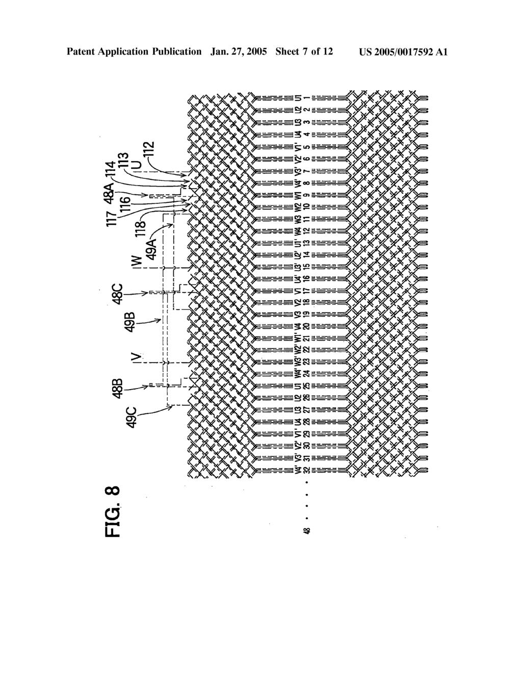
15 Jan. 27, FIG. 4 is a circuit diagram showing a connection of the armature winding as a first embodiment of the present invention; 0017 FIG. 5 is a circuit diagram showing a part of the connection shown in FIG. 4 in an enlarged Scale; FIG. 6 is a diagram showing an armature winding disposed in Slots of an armature core; FIG. 7 is a part of the same diagram as shown in FIG. 6 to be continued thereto; 0020 FIG. 8 is a diagram showing an armature winding disposed in Slots of an armature core as a Second embodi ment of the present invention; 0021 FIG. 9 is a circuit diagram showing a connection of the armature winding as a Second embodiment of the present invention; 0022 FIG. 10 is a circuit diagram showing a connection of the armature winding as a third embodiment of the present invention; 0023 FIG. 11 is a diagram showing the armature wind ing disposed in Slots of an armature core as the third embodiment of the present invention; 0024 FIG. 12 is a circuit diagram showing a connection of an armature winding as a fourth embodiment of the present invention; FIG. 13 is a circuit diagram showing a connection of an armature winding as a fifth embodiment of the present invention; FIG. 14 is a circuit diagram showing a connection of an armature winding as a sixth embodiment of the present invention; FIG. 15 is a circuit diagram showing a connection of an armature winding as a first comparative example, 0028 FIG. 16 is a circuit diagram showing a connection of an armature winding as a Second comparative example; and 0029 FIG. 17 is a circuit diagram showing an armature winding in a conventional rotary electric machine. DETAILED DESCRIPTION OF THE PREFERRED EMBODIMENTS A first embodiment of the present invention will be described with reference to FIGS In FIG. 1, an alternating current motor to which the present invention is applied is shown. The motor is composed of a housing 10 including a front housing 11 and a rear housing 16, an armature 30 fixed in the housing 10, a rotor 25 rotatably Supported in the housing with a pair of bearings 12 and 17. The front housing 11 and the rear housing 16 are connected to each other by connecting bolts. The armature 30 is composed of an armature core 32 fixed to the housing 10 and an armature winding 35 disposed in slots 33 formed in the armature core 32. The rotor 25 is composed of a rotor shaft 20, a rotor core 26 fixed to the rotor shaft 20 and permanent magnets 27 embedded in the rotor core 26. Rotational torque of the motor is taken out from a pulley (not shown) con nected to the rotor shaft ) The armature 30 will be described in detail with reference to FIGS The armature core 32 has a cylin drical shape, and the plural slots 33 (48 slots in this particular embodiment) are formed in its inner bore at equal intervals. As shown in FIG. 2, neighboring 4 slots form a group of slots for containing respective phase windings. For example, a group of slots 33a for U-phase windings U1-U4 is composed of four slots, 33a1, 33a2, 33.a3 and 33.a4. Similarly, a group of slots 33b for V-phase windings V1-V4 is composed of four slots, and a group of Slots 33c for W-phase windings W1-W4 is composed of four slots Conductor segments including inner conductor Segments 37 and Outer conductor Segments 42, shown in FIG. 3, are disposed in the slots 33 with an insulator (not shown) interposed therebetween. The inner conductor Seg ment 37 is formed by bending a conductor wire such as a copper wire having a rectangular cross-section. The inner conductor Segment 37 has a pair of Straight portions 38a, 38b which are disposed in the slots 33, a U-shaped portion 39 connecting the pair of straight portions 38a, 38b, and a pair of angled portions 41a, 41b. The angled portions 41a and 41b are bent so that they become close to each other. The angled portions 41a, 41b include respective end portions 40a, 40b. The outer conductor segment 42 is similarly formed and has a pair of straight portions 43a, 43b which are disposed in the slots 33, a U-shaped portion 44 connecting the pair of Straight portions 43a, 43b, and a pair of angled portions 45a, 45b. The angled portions 45a, 45b are bent so that they become apart from each other. The angle portions 45a, 45b include respective end portions 46a, 46b.Other conductor Segments to be electrically connected to the conductor segments 37 and 42 are shown with dotted lines The U-shaped portions 39, 44 extend from an axial end surface of the armature core 32 (to the right side in FIG. 1), and the angled portions 41a, 41b, 45a, 45b extend from the other axial endsurface of the armature core 32 (to the left side in FIG. 1). The end portions 4.0a and 46a, and the end portions 40b and 46b are electrically connected to each other. Plural inner conductor segments 37 and plural outer conductor Segments 42 form the phase-windings, U-phase winding, V-phase winding and W-phase winding in the manner described below As shown in FIG. 4, the armature winding 35 has a pair of delta-star windings 47 and 47". Since both windings 47 and 47" are identical, the delta-star winding 47 will be described in detail. Both windings 47 and 47" are connected in parallel. The delta-star winding 47 includes a delta winding 50 composed of a first U-phase winding Ua, a first V-phase winding Va and a first W-phase winding Wa, and a star winding 70 composed of a second U-phase winding Ub, a second V-phase winding Vb and a second W-phase wind ing Wb. Ua, Va and Wa are disposed in the respective slots 33, each being apart from one another by 120 electrical angle, and are connected in a delta connection. Ub, Vb and Wb are disposed in the respective slots 33, each being apart from one another by 120 electrical angle, and are connected in a Star connection. 0035). As shown in FIG. 5, Ub and Ua are composed of U-phase winding units U1, U2 and U3, U4, respectively. U1-U4 are connected in series. Similarly, Vb and Va are composed of V-phase winding units V1, V2 and V3, V4, respectively. V1-V4 are connected in series. Wh and Wa are

16 Jan. 27, 2005 composed of W-phase winding units W1, W2 and W3, W4, respectively. W1-W4 are connected in series. The delta winding 50 has junctions 48A, 48B and 48C, and the star-winding 70 has phase terminals U, V and W The other delta-star winding 47 includes a delta winding 50' having junctions 48A, 48B' and 48C and a star-winding 70' having phase terminals U, V and W". The pair of delta-star windings 47 and 47" are connected in parallel, i.e., the phase terminals U and U" are connected to a common U-phase terminal 80U, the phase terminals V and V" are connected to a common V-phase terminal 80V and the phase terminals W and W are connected to a common W-phase terminal 80W Referring to FIGS. 6 and 7, how the conductor segments 37, 42 are disposed in the slots 33 to form the armature winding 35 will be described in detail. The straight portion 38a of the inner conductor segment 37 and the Straight portion 43a of the outer conductor segment 42 (refer to FIG. 3) are disposed in one slot 33, and the straight portion 38b of the inner conductor segment 37 and the Straight portion 43b of the outer conductor Segment 42 are disposed in the other slot 33. The former slot and the latter slot are 180 electrical angle apart from each other. In this manner, four Strait portions of the conductor Segments 37, 42 are disposed in each slot 33. The first layer in the slot 33 (the layer closest to the rotational axis of the motor) is shown in FIGS. 6 and 7 with a chained line with one dot, the second layer with a broken line, the third layer with a solid line and the fourth layer with a chained line with two dots As shown in FIGS. 6 and 7, the U-phase winding unit U1 is wound around the armature core (one round) in the following path: the second layer in the 1 slot, the first layer in the 13" slot, the fourth layer in the 25" slot, the third layer in the 37" slot, the fourth layer in the 1 slot, and the third layer in the 13" slot. The winding unit U2 is wound around the armature core (one round) from the Second layer in the 2" slot, the first layer in the 14" slot..., then connected to the junction 48A. The winding units U1 and U2 are connected to each other using a Special Segment 42A (straight portions in a regular segment are apart from each other by 12 Slots, while those in a special Segment by 11 slots). The winding unit U3 is wound around the armature core, Starting from the junction 48A through the Second layer in the 3' slot, the first layer in the 15" th slot... and so on. The winding unit U4 starts from the second layer in the in the 4" slot, which continues to the third layer in the 15" slot, through the first layer in the 16"..., and reaches the junction 48B. The winding units U3 and U4 are connected to each other using the Special Segment 42B. The W-phase winding unit W4 extending from the third layer in 24" slot is connected to the junction 48A, at which U2 and U3 are connected, through a lead wire 49A The V-phase winding unit V1 extends from the 17" slot... to the 5" slot. V2 extends from the 18" slot... to the 6" slot. V3 extends from the 19" slot... to the 7" slot. V4 extends from the 20" slot... to the 8" slot. Each of the V-phase winding units V1-V4 makes one full round around the armature core. The U-phase winding unit U4 extending from the third layer in the 16" th slot is connected to the junction 48B, at which V2 and V3 are connected, through a lead wire 49B The W-phase winding unit W1 extends from the 9" slot... to the 45" slot, W2 from the 10" slot... to the 46" slot, W3 from the 11" slot... to the 47" slot, and W4 from the 12" slot... to the 48" slot. Each of the W-phase winding units W1-W4 makes one round around the armature core. The V-phase winding unit V4 extending from the fourth layer in the 32" slot is connected to the junction 48C, at which W2 and W3 are connected, through a lead wire 49C The second U-phase winding Ub consisting of U1 and U2 is connected to the first U-phase winding Ua consisting of U3 and U4 at junction 48A which is in turn connected to the first W-phase winding Wa consisting of W3 and W4. Ub is connected to Ua after Ub makes two rounds around the armature core, and then Ua makes two rounds. The V-phase windings and the W-phase windings are con nected in the Same manner as the U-phase windings, as shown in FIGS. 4 and 5. The other delta-star winding 47' is formed in the same manner. The pair of delta-star windings 47 and 47, however, are wound in the opposite directions around the armature core 32. For example, U1 of the delta-star winding 47 extends from the second layer in the 1 slot toward the left side in FIG. 6, while U1 of the other delta-star winding 47 extends from the first layer in the 1 Slot toward the right Side As shown in FIG. 4, the pair of delta-star windings 47, 47" are connected in parallel to each other. The U-phase winding unit U1 of the delta-star winding 47 and the U-phase winding unit U1' of the other delta-star winding 47 are commonly led out from the 1 slot and connected to the common U-phase terminal 80U. Similarly, V1 and V1' are commonly led out from the 17" slot and connected to the common V-phase terminal 80V. W1 and W1' are commonly led out from the 9" slot and connected to the common W-phase terminal 80W Electric power to drive the motor is supplied from a direct current Source (not shown) through an inverter (not shown) to the three-phase common terminals 80U, 80V and 80W. The electric motor is driven in the known manner, i.e., the positions of the permanent magnets 27 are detected, and current is Supplied to a phase winding determined by the positions of the permanent magnets 27. The rotor 25 is rotated by electromagnetic force between the rotor 25 and the armature ) The following advantages are obtained in the first embodiment described above. First, the number of armature winding turns which lies between those of the delta-winding and the Star-winding is realized. The number of winding turns (corresponding to the number of Series conductors per each pole and each phase) of each phase winding unit (U1-U4, V1-V4, W1-W4) is 2. Therefore, the star-connec tion-equivalent number of turns in the delta winding 50 is: (2 +2)/V3s2.3. Accordingly, the equivalent number of turns in the entire delta-start winding 47 is: 2+2+(2+2)/V If the same winding units are connected in the Star-connection as shown in FIG. 15 (comparative example), the equivalent number of turns is 8. On the other hand, if the same winding units are connected in the delta-connection as shown in FIG. 16 (comparative example), the equivalent number of turns is: 8/V3s4.6. The equivalent number of turns 6.3 realized in the first embodiment lies between 8 in the star-connection and 4.6 in the delta-connection In the star-connection shown in FIG. 15, U4, V4 and W4 are connected at one common point. To change the star-connection shown in FIG. 15 to the delta-star connec

17 Jan. 27, 2005 tion shown in FIG. 5, one end of U4 is connected to a junction of V2 and V3. Other phase windings are similarly changed. On the other hand, to change the delta-connection shown in FIG. 16 to the delta-star connection shown in FIG. 5, one end of U4 is connected to a junction of V2 and V3. Other phase windings are Similarly changed. Since the U-shaped portions 39, 44 of the conductor segments 37, 42 are positioned at the axial end of the armature core 32, these connection changes can be easily done. 0046) Secondly, since the pair of delta-star windings 47 and 47" are connected in parallel, a large current capacity can be realized. Thirdly, Since the phase windings to be con nected to the phase terminals are led out from the same slots which are common to both delta-star windings 47, 47", the Structure of the armature winding 35 can be made Simple. Lastly, since the lead wires 49A, 49B and 49C are positioned within a half circular area (within 180 of the central angle) on the axial end of the armature core 32, the length of the lead wires can be shortened. By shortening the lead wires, the power loss can be reduced A second embodiment of the present invention will be described with reference to FIGS. 8 and 9. In this embodiment, phase-winding units of both the delta-star windings 47 and 47" are connected in series. That is, as shown in FIG. 9, the winding units U1, U1, U2' and U2 are connected in Series in this order, forming a U-phase winding in a star-winding 105. Other phase windings in the star winding 105 are similarly formed. The winding units U3, U3, U4' and U4 are connected in series in this order, forming a U-phase winding in a delta-winding 110. Other phase windings in the delta-winding 110 are similarly formed In the star winding 105, as shown in FIG. 8, the U-phase winding unit U1 proceeds from the first layer in the 1 slot toward the right side and reaches the fourth layer in the 13" slot. U1' proceeds from the second layer in the 1 slot toward the left side and reaches the third layer in the 13" slot. The fourth layer in the 13" slot and the second layer in the 1" slot are connected by a reversal conductor segment 112. U2 proceeds from the second layer in the 2" slot toward the left side and reaches the third layer in the 14" slot. The third layer in the 13" slot and the second layer in the 2" ind slot are connected by a special segment 113. U2 proceeds from the first layer in the 2" ind slot toward the right side and reaches the fourth layer in the 14" slot. The third layer in the 14" slot and the first layer in the 2" slot are connected by a reversal Segment 114. U2 extending from the fourth layer in the 14" th slot is connected to the junction 48A In the delta-winding 110, U3 and U3' are connected by a reversal segment 116, U3" and U4' are connected by a special segment 117, and U4 and U4 are connected by a reversal segment 118. An end of U4 is connected to the junction 48B The equivalent number of turns (converted to a star-winding) of the delta-winding 110 is: (4+4)/V3s4.5. The equivalent number of turns of the delta-star winding (a combination of 110 and 105) is: 8+8/V3s In this second embodiment, the phase winding units, each proceeding in different directions, are connected in Series by the reversal segments 112, 114, 116 and 118. In this manner, the pair of delta-star windings connected in parallel (as in the first embodiment) can be changed to the winding shown in FIG. 9 without making major changes. Since the equivalent number of turns in the Second embodiment is high, the Second embodiment is applicable to a higher Voltage System A third embodiment of the present invention will be described with reference to FIGS. 10 and 11. In this embodiment, a pair of the delta-star windings 160 shown in FIG. 10 are connected in parallel as in the first embodiment. However, the winding structure is modified from the first embodiment. That is, the delta-winding 150 is composed of U4, V4 and W4. In other words, each phase winding in the delta-winding 150 is formed only one phase winding unit. The rest of the phase windings (U1, U2 and U3 in the U-phase, for example) are all used for forming the Star winding The winding structure of the third embodiment is shown in FIG. 11. An end of U3 is led out from the 15" slot, an end of U4 is led out from the 4" slot, and an end of W4 is led out from the 24" slot. These ends are connected at the junction 48A. An end of V3 is led out from the 31 slot, an end of V4 is led out from 20" slot, and an end of U4 is led out from the 16" slot. These ends are connected at the junction 48B. An end of W3 led out from the 23" slot and an end of W4 led out from the 12" slot and an end of V4 led out from the 32" slot are connected at the junction 48C The number of turns of each phase winding unit is all equal and 2. The equivalent number of turns of the delta-winding 150 is: 2/V3s 7. Accordingly, the equivalent number of turns of the delta-star winding 160 is: 6+2/V3-7. If all the winding units are connected in a pure Star-winding, the equivalent number of turns is 8. This means that the equivalent number of turns can be easily changed from 8 to 7 by Simply changing the positions of the junctions 48A, 48B and 48C. Comparing this third embodiment with the first embodiment, led out positions of U2, U3 and U4 are slightly different. That is, U2 is led out from the 14" slot in the first embodiment, while U3 is led out from the 15" slot in the third embodiment. U3 is led out from the 3' slot in the first embodiment while U4 is led out from the 4" slot in the third embodiment. Other phase windings V and W are Similarly Structured. Thus, the equivalent number of turns can be easily change by Simply moving the positions of the junctions 48A, 48B and 48C. Comparing the third embodi ment with the first embodiment, these positions are moved by only one slot. Though the pair of delta-star windings 160 are connected in parallel in this third embodiment, it is, of course, possible to connect them in Series as done in the Second embodiment. 0054) A fourth embodiment of the present invention will be described with reference to FIG. 12. A pair of delta-star windings 210 are connected in parallel in this embodiment, too. A delta-winding 200 is composed of three phase wind ing units in each phase, e.g., U2, U3 and U4 in the U-phase. In other words, each phase winding in the delta-winding 200 is formed by making three rounds around the armature core 32. A star-winding 205 is formed by only three phase winding units U1, V1 and W1. Since the number of turns of each phase winding unit is 2 (the same as in the foregoing embodiment), the equivalent number of turns (the Star winding equivalent) of the delta-winding 200 is: 6/V Accordingly, the equivalent number of turns of the delta-star winding 210 is: 2+6/V The equivalent number of turns

18 Jan. 27, in the pure Star-connection is changed to 5.4 by Simply changing the positions of the junctions 48A, 48B and 48C Though the pair of the delta-star winding 210 are connected in parallel in this embodiment, it is also possible to connect each winding unit in Series as in the Second embodiment. By connecting two phase winding units in Series, the number of turns becomes 4 each. Accordingly, the equivalent number of turns of the delta-star winding becomes: 4+12/V3s,11. As understood from the first embodi ment, the third embodiment and the fourth embodiment, it is possible to change the positions of the junctions at three Steps, because each phase includes four winding units, e.g., U1, U2, U3 and U4 in the U-phase. By simply changing the positions of the junctions, the motor can be made applicable to the Systems having various Voltages and various current capacities. Further, in the first, third and fourth embodi ments, it is possible to Switch the pair of delta-star windings connected in parallel to the Series connection by Simply changing the positions of the junctions using the reversal Segments A fifth embodiment of the present invention will be described with reference to FIG. 13. A pair of delta-star windings 260 are connected in Series in this embodiment, too. In this embodiment, however, three winding units are used in each phase instead of four winding units. That is, U-phase winding is formed three winding units U1, U2 and U3 connected in Series. The same is applied to other phases V and W. Adelta winding 250 is formed by U3, V3 and W3 connected in delta connection at junctions 48A, 48B and 48C. A star-winding 255 is formed by six winding units U1, U2; V1, V2; W1, W2. Each winding unit forming the delta-winding 250, i.e., U3, V3, W3, is connected to the junction 48A, 48B, 48C after making one round around the armature core The equivalent number of turns of the delta-wind ing 250 is: 2/V3s 1. Accordingly, the equivalent number of turns of the delta-star winding 260 is: 4+2/V3-5. If all the winding units are connected in pure Star-connection, the equivalent number of turns is 6. This means that the equiva lent number of turns 5 is realized by Simply changing the positions of the junctions. The pair of delta-star windings 260 may be connected in Series in the Similar manner as in the Second embodiment. In this case, the equivalent number of turns is: 8+4/V3s Asixth embodiment of the present invention will be described with reference to FIG. 14. A delta-star winding 310 is composed of a delta-winding 300 and a star-winding 305. In this embodiment, the junctions 48A, 48B, 48C in the fifth embodiment are moved to enlarge the delta-winding 300. Each phase winding (composed of two winding units) in the delta-winding 300 is connected in a delta-connection after it makes two rounds around the armature core 32. Since one round includes two winding turns, each phase of the delta-winding 300 includes four turns. The star-winding 305 is formed by three winding units U1, V1 and W1. The equivalent number of turns of the delta-star winding 310 is: 2+4/V3s4.3. A pair of delta-star windings 310 may be connected in Series in the same manner as in the Second embodiment. In this case, the equivalent number of turns is: 4+8/V While the present invention has been shown and described with reference to the foregoing preferred embodi ments, it will be apparent to those skilled in the art that changes in form and detail may be made therein without departing from the Scope of the invention as defined in the appended claims. What is claimed is: 1. An armature of a rotary electric machine, the armature including a cylindrical armature core having a plurality of Slots and an armature winding wound around the armature core, the armature winding comprising a plurality of con ductor Segments, each having a pair of Straight portions disposed in the Slots and a U-shaped portion connecting the pair of Straight portions, wherein: the armature winding is a delta-star winding which is a combination of a delta-winding connected in a delta connection and a Star-winding connected in a Star connection; the delta-winding is composed of first three phase wind ings, a first U-phase winding (Ua), a first V-phase winding (Va), and a first W-phase winding (Wa), each first phase winding being wound by n (integer) turns; the Star-winding is composed of Second three phase windings, a second U-phase winding (Ub) one end of which is connected to a point (48A) connecting (Ua) and (Wa), a second V-phase winding (Vb) one end of which is connected to a point (48B) connecting (Ua) and (Va), and a second W-phase winding (Wb) one end of which is connected to a point (48C) connecting (Va) and (Wa), each Second phase winding being wound by m (integer) turns; and the armature winding includes turn-ratio changing means for changing a turn-ratio (n/m) by changing positions of the points (48A), (48B) and (48C). 2. The armature of a rotary electric machine as in claim 1, wherein: a U-phase winding is composed of three or more U-phase winding units (U1, U2, U3... ) connected in Series, a part of Such units constitutes the first U-phase winding (Ua) and the rest constitutes the Second U-phase wind ing (Ub); a V-phase winding is composed of three or more V-phase winding units (V1,V2, V3....) connected in series, a part of Such units constitutes the first V-phase winding (Va) and the rest constitutes the second V-phase wind ing (Vb); and a W-phase winding is composed of three or more W-phase winding units (W1, W2, W3...) connected in series, a part of such units constitutes the first W-phase wind ing (Wa) and the rest constitutes the second W-phase winding (Wb). 3. The armature of a rotary electric machine as in claim 2, wherein: lead wires led out from all of the first and second three-phase windings (Ua, Ub, Va, Vb, Wa, Wb) are positioned at one axial end of the cylindrical armature core within 180 degrees in the central angle of the armature COre. 4. An armature of a rotary electric machine, the armature including a cylindrical armature core having a plurality of Slots and an armature winding wound around the armature core, the armature winding comprising a plurality of con

19 Jan. 27, 2005 ductor Segments, each having a pair of Straight portions disposed in the Slots and a U-shaped portion connecting the pair of Straight portions, wherein: the armature winding is composed of a pair of delta-star windings which are connected in parallel, each delta Star winding being a combination of a delta-winding connected in a delta-connection and a Star-winding connected in a Star-connection; the delta-winding is composed of first three phase wind ings, a first U-phase winding (Ua), a first V-phase winding (Va), and a first W-phase winding (Wa), each first phase winding being wound by n (integer) turns; the Star-winding is composed of Second three phase windings, a second U-phase winding (Ub) one end of which is connected to a point (48A) connecting (Ua) and (Wa), a second V-phase winding (Vb) one end of which is connected to a point (48B) connecting (Ua) and (Va), and a second W-phase winding (Wb) one end of which is connected to a point (48C) connecting (Va) and (Wa), each Second phase winding being wound by m (integer) turns; and the armature winding includes turn-ratio changing means for changing a turn-ratio (n/m) by changing positions of the points (48A), (48B) and (48C). 5. The armature of a rotary electric machine as in claim 4, wherein: the first U-phase windings (Ua) of both the delta-star windings, the first V-phase windings (Va) of both the delta-star windings, the first W-phase windings (Wa) of both the delta-star windings, the Second U-phase wind ings (Ub) of both the delta-star windings, the Second V-phase windings (Vb) of both the delta-star windings and the second W-phase windings (Wb) of both the delta-star windings are disposed in a Same slot, respec tively, and have lead wires extending from the same slot, respectively. 6. The armature of a rotary electric machine as in claim 5, wherein: the lead wires extending from all of the first and Second phase windings (Ua, Va, Wa, Ub, Vb, Wb) of the both delta-star windings are positioned at one axial end of the cylindrical armature core within 180 degrees in the central angle of the armature core. 7. An armature of a rotary electric machine, the armature including a cylindrical armature core having a plurality of Slots and an armature winding wound around the armature core, the armature winding comprising a plurality of con ductor Segments, each having a pair of Straight portions disposed in the Slots and a U-shaped portion connecting the pair of Straight portions, wherein: the armature winding is composed of a pair of delta-star windings, each delta-star winding being a combination of a delta-winding connected in a delta-connection and a Star-winding connected in a Star-connection; the delta-winding is composed of first three phase wind ings, a first U-phase winding (Ua), a first V-phase winding (Va), and a first W-phase winding (Wa); the Star-winding is composed of Second three phase windings, a second U-phase winding (Ub) one end of which is connected to a point (48A) connecting (Ua) and (Wa), a second V-phase winding (Vb) one end of which is connected to a point (48B) connecting (Ua) and (Va), and a second W-phase winding (Wb) one end of which is connected to a point (48C) connecting (Va) and (Wa); and the armature winding includes connection changeover means for changing a connection in the pair of delta Star windings between a Series connection, in which each phase winding in one delta-star winding is con nected in Series to each phase winding in the other delta-star winding, and a parallel connection in which both the delta-star windings are connected in parallel as a whole.
(12) United States Patent (10) Patent No.: US 9,564,782 B2. Kimura et al. (45) Date of Patent: Feb. 7, 2017
 United States Patent (10) Patent No.: US 9,564,782 B2. Kimura et al. (45) Date of Patent: Feb. 7, 2017") USO09564782B2 (12) United States Patent () Patent No.: Kimura et al. (45) Date of Patent: Feb. 7, 2017 (54) WINDING, WINDING METHOD, AND (56) References Cited AUTOMOTIVE ROTATING ELECTRIC MACHINE U.S.
USO09564782B2 (12) United States Patent () Patent No.: Kimura et al. (45) Date of Patent: Feb. 7, 2017 (54) WINDING, WINDING METHOD, AND (56) References Cited AUTOMOTIVE ROTATING ELECTRIC MACHINE U.S.
(12) Patent Application Publication (10) Pub. No.: US 2001/ A1
 Patent Application Publication (10) Pub. No.: US 2001/ A1") US 2001 004.8356A1 (19) United States (12) Patent Application Publication (10) Pub. No.: US 2001/0048356A1 Owen (43) Pub. Date: Dec. 6, 2001 (54) METHOD AND APPARATUS FOR Related U.S. Application Data
US 2001 004.8356A1 (19) United States (12) Patent Application Publication (10) Pub. No.: US 2001/0048356A1 Owen (43) Pub. Date: Dec. 6, 2001 (54) METHOD AND APPARATUS FOR Related U.S. Application Data
IIH. United States Patent (19) Chen. (11) Patent Number: 5,318,090 (45. Date of Patent: Jun. 7, 1994
 Chen. (11) Patent Number: 5,318,090 (45. Date of Patent: Jun. 7, 1994") United States Patent (19) Chen 54) ROLLER ASSEMBLY FORVENETIAN BLIND 76 Inventor: Cheng-Hsiung Chen, No. 228, Sec. 2, Chung-Te Rd., Taichung City, Taiwan 21 Appl. No.: 60,278 22 Filed: May 11, 1993 51)
United States Patent (19) Chen 54) ROLLER ASSEMBLY FORVENETIAN BLIND 76 Inventor: Cheng-Hsiung Chen, No. 228, Sec. 2, Chung-Te Rd., Taichung City, Taiwan 21 Appl. No.: 60,278 22 Filed: May 11, 1993 51)
A Practical Guide to Free Energy Devices
 A Practical Guide to Free Energy Devices Part PatD21: Last updated: 29th November 2006 Author: Patrick J. Kelly This patent covers a device which is claimed to have a greater output power than the input
(12) United States Patent
 United States Patent") USOO9206864B2 (12) United States Patent Krusinski et al. (10) Patent No.: (45) Date of Patent: US 9.206,864 B2 Dec. 8, 2015 (54) (71) (72) (73) (*) (21) (22) (65) (60) (51) (52) (58) TORQUE CONVERTERLUG
USOO9206864B2 (12) United States Patent Krusinski et al. (10) Patent No.: (45) Date of Patent: US 9.206,864 B2 Dec. 8, 2015 (54) (71) (72) (73) (*) (21) (22) (65) (60) (51) (52) (58) TORQUE CONVERTERLUG
United States Patent (19) Lin
 Lin") United States Patent (19) Lin 11) 45) Dec. 22, 1981 54) (76) (21) 22 (51) (52) (58) (56) BUILDING BLOCK SET Inventor: Wen-Ping Lin, 30, Chien-Yung St., Taichung, Taiwan Appl. No.: 187,618 Filed: Sep. 15,
United States Patent (19) Lin 11) 45) Dec. 22, 1981 54) (76) (21) 22 (51) (52) (58) (56) BUILDING BLOCK SET Inventor: Wen-Ping Lin, 30, Chien-Yung St., Taichung, Taiwan Appl. No.: 187,618 Filed: Sep. 15,
(12) Patent Application Publication (10) Pub. No.: US 2007/ A1
 Patent Application Publication (10) Pub. No.: US 2007/ A1") (19) United States (12) Patent Application Publication (10) Pub. No.: US 2007/0132875 A1 Lee et al. US 20070132875A1 (43) Pub. Date: Jun. 14, 2007 (54) (75) (73) (21) (22) (30) OPTICAL LENS SYSTEM OF MOBILE
(19) United States (12) Patent Application Publication (10) Pub. No.: US 2007/0132875 A1 Lee et al. US 20070132875A1 (43) Pub. Date: Jun. 14, 2007 (54) (75) (73) (21) (22) (30) OPTICAL LENS SYSTEM OF MOBILE
(12) Patent Application Publication (10) Pub. No.: US 2005/ A1. Chen et al. (43) Pub. Date: Dec. 29, 2005
 Patent Application Publication (10) Pub. No.: US 2005/ A1. Chen et al. (43) Pub. Date: Dec. 29, 2005") US 20050284393A1 (19) United States (12) Patent Application Publication (10) Pub. No.: Chen et al. (43) Pub. Date: Dec. 29, 2005 (54) COLOR FILTER AND MANUFACTURING (30) Foreign Application Priority Data
US 20050284393A1 (19) United States (12) Patent Application Publication (10) Pub. No.: Chen et al. (43) Pub. Date: Dec. 29, 2005 (54) COLOR FILTER AND MANUFACTURING (30) Foreign Application Priority Data
(12) United States Patent
 United States Patent") (12) United States Patent Schwab et al. US006335619B1 (10) Patent No.: (45) Date of Patent: Jan. 1, 2002 (54) INDUCTIVE PROXIMITY SENSOR COMPRISING ARESONANT OSCILLATORY CIRCUIT RESPONDING TO CHANGES IN
(12) United States Patent Schwab et al. US006335619B1 (10) Patent No.: (45) Date of Patent: Jan. 1, 2002 (54) INDUCTIVE PROXIMITY SENSOR COMPRISING ARESONANT OSCILLATORY CIRCUIT RESPONDING TO CHANGES IN
(12) Patent Application Publication (10) Pub. No.: US 2012/ A1. T (43) Pub. Date: Dec. 27, 2012
 Patent Application Publication (10) Pub. No.: US 2012/ A1. T (43) Pub. Date: Dec. 27, 2012") US 20120326936A1 (19) United States (12) Patent Application Publication (10) Pub. No.: US 2012/0326936A1 T (43) Pub. Date: Dec. 27, 2012 (54) MONOPOLE SLOT ANTENNASTRUCTURE Publication Classification (75)
US 20120326936A1 (19) United States (12) Patent Application Publication (10) Pub. No.: US 2012/0326936A1 T (43) Pub. Date: Dec. 27, 2012 (54) MONOPOLE SLOT ANTENNASTRUCTURE Publication Classification (75)
(12) Patent Application Publication (10) Pub. No.: US 2016/ A1
 Patent Application Publication (10) Pub. No.: US 2016/ A1") (19) United States US 2016.00200O2A1 (12) Patent Application Publication (10) Pub. No.: US 2016/0020002 A1 FENG (43) Pub. Date: Jan. 21, 2016 (54) CABLE HAVING ASIMPLIFIED CONFIGURATION TO REALIZE SHIELDING
(19) United States US 2016.00200O2A1 (12) Patent Application Publication (10) Pub. No.: US 2016/0020002 A1 FENG (43) Pub. Date: Jan. 21, 2016 (54) CABLE HAVING ASIMPLIFIED CONFIGURATION TO REALIZE SHIELDING
(12) Patent Application Publication (10) Pub. No.: US 2001/ A1
 Patent Application Publication (10) Pub. No.: US 2001/ A1") US 2001 0021611A1 (19) United States (12) Patent Application Publication (10) Pub. No.: US 2001/0021611 A1 Onizuka et al. (43) Pub. Date: Sep. 13, 2001 (54) BUS BAR STRUCTURE Related U.S. Application Data
US 2001 0021611A1 (19) United States (12) Patent Application Publication (10) Pub. No.: US 2001/0021611 A1 Onizuka et al. (43) Pub. Date: Sep. 13, 2001 (54) BUS BAR STRUCTURE Related U.S. Application Data
A Practical Guide to Free Energy Devices
 A Practical Guide to Free Energy Devices Device Patent No 30: Last updated: 24th June 2007 Author: Patrick J. Kelly This patent shows a method of altering a standard electrical generator intended to be
YARIABLE YEASEf 55. United States Patent (19) 4,743, INPUT OUTPUT, 54 al. Shilling et al. May 10, 1988
 4,743, INPUT OUTPUT, 54 al. Shilling et al. May 10, 1988") United States Patent (19) Shilling et al. 11 Patent Number: (45. Date of Patent: 4,743,777 May 10, 1988 54 STARTER GENERATOR SYSTEM WITH TWO STATOR EXCITER WINDINGS (75 Inventors: William J. Shilling,
United States Patent (19) Shilling et al. 11 Patent Number: (45. Date of Patent: 4,743,777 May 10, 1988 54 STARTER GENERATOR SYSTEM WITH TWO STATOR EXCITER WINDINGS (75 Inventors: William J. Shilling,
TEPZZ A T EP A2 (19) (11) EP A2 (12) EUROPEAN PATENT APPLICATION. (51) Int Cl.: H02K 11/04 ( )
 (11) EP A2 (12) EUROPEAN PATENT APPLICATION. (51) Int Cl.: H02K 11/04 ( )") (19) TEPZZ 765688A T (11) EP 2 765 688 A2 (12) EUROPEAN PATENT APPLICATION (43) Date of publication: 13.08.2014 Bulletin 2014/33 (51) Int Cl.: H02K 11/04 (2006.01) (21) Application number: 14154185.4 (22)
(19) TEPZZ 765688A T (11) EP 2 765 688 A2 (12) EUROPEAN PATENT APPLICATION (43) Date of publication: 13.08.2014 Bulletin 2014/33 (51) Int Cl.: H02K 11/04 (2006.01) (21) Application number: 14154185.4 (22)
Kiuchi et al. (45) Date of Patent: Mar. 8, 2011
 Date of Patent: Mar. 8, 2011") (12) United States Patent US007902952B2 (10) Patent No.: Kiuchi et al. (45) Date of Patent: Mar. 8, 2011 (54) SHARED REACTOR TRANSFORMER (56) References Cited (75) Inventors: Hiroshi Kiuchi, Chiyoda-ku
(12) United States Patent US007902952B2 (10) Patent No.: Kiuchi et al. (45) Date of Patent: Mar. 8, 2011 (54) SHARED REACTOR TRANSFORMER (56) References Cited (75) Inventors: Hiroshi Kiuchi, Chiyoda-ku
United States Patent (19) Nihei et al.
 Nihei et al.") United States Patent (19) Nihei et al. 54) INDUSTRIAL ROBOT PROVIDED WITH MEANS FOR SETTING REFERENCE POSITIONS FOR RESPECTIVE AXES 75) Inventors: Ryo Nihei, Akihiro Terada, both of Fujiyoshida; Kyozi
United States Patent (19) Nihei et al. 54) INDUSTRIAL ROBOT PROVIDED WITH MEANS FOR SETTING REFERENCE POSITIONS FOR RESPECTIVE AXES 75) Inventors: Ryo Nihei, Akihiro Terada, both of Fujiyoshida; Kyozi
(12) Patent Application Publication (10) Pub. No.: US 2007/ A1
 Patent Application Publication (10) Pub. No.: US 2007/ A1") (19) United States US 20070147825A1 (12) Patent Application Publication (10) Pub. No.: US 2007/0147825 A1 Lee et al. (43) Pub. Date: Jun. 28, 2007 (54) OPTICAL LENS SYSTEM OF MOBILE Publication Classification
(19) United States US 20070147825A1 (12) Patent Application Publication (10) Pub. No.: US 2007/0147825 A1 Lee et al. (43) Pub. Date: Jun. 28, 2007 (54) OPTICAL LENS SYSTEM OF MOBILE Publication Classification
United States Patent (19) Sun
 Sun") United States Patent (19) Sun 54 INFORMATION READINGAPPARATUS HAVING A CONTACT IMAGE SENSOR 75 Inventor: Chung-Yueh Sun, Tainan, Taiwan 73 Assignee: Mustek Systems, Inc., Hsinchu, Taiwan 21 Appl. No. 916,941
United States Patent (19) Sun 54 INFORMATION READINGAPPARATUS HAVING A CONTACT IMAGE SENSOR 75 Inventor: Chung-Yueh Sun, Tainan, Taiwan 73 Assignee: Mustek Systems, Inc., Hsinchu, Taiwan 21 Appl. No. 916,941
(12) Patent Application Publication (10) Pub. No.: US 2005/ A1
 Patent Application Publication (10) Pub. No.: US 2005/ A1") US 20050207013A1 (19) United States (12) Patent Application Publication (10) Pub. No.: US 2005/0207013 A1 Kanno et al. (43) Pub. Date: Sep. 22, 2005 (54) PHOTOELECTRIC ENCODER AND (30) Foreign Application
US 20050207013A1 (19) United States (12) Patent Application Publication (10) Pub. No.: US 2005/0207013 A1 Kanno et al. (43) Pub. Date: Sep. 22, 2005 (54) PHOTOELECTRIC ENCODER AND (30) Foreign Application
IIII - HH. United States Patent 19. Nagamitsu et al. 11 Patent Number: 5,765, Date of Patent: Jun. 16, 1998
 United States Patent 19 Nagamitsu et al. 54 SPACE-SAVING WORKING EQUIPMENT (75) Inventors: Satoshi Nagamitsu, Higashiyamato; Hidemi Yaguchi, Mitsukaido; Yuji Yoshida, Yawara-mura, all of Japan 73) Assignee:
(12) United States Patent (10) Patent No.: US 7,859,376 B2. Johnson, Jr. (45) Date of Patent: Dec. 28, 2010
 United States Patent (10) Patent No.: US 7,859,376 B2. Johnson, Jr. (45) Date of Patent: Dec. 28, 2010") US007859376B2 (12) United States Patent (10) Patent No.: US 7,859,376 B2 Johnson, Jr. (45) Date of Patent: Dec. 28, 2010 (54) ZIGZAGAUTOTRANSFORMER APPARATUS 7,049,921 B2 5/2006 Owen AND METHODS 7,170,268
US007859376B2 (12) United States Patent (10) Patent No.: US 7,859,376 B2 Johnson, Jr. (45) Date of Patent: Dec. 28, 2010 (54) ZIGZAGAUTOTRANSFORMER APPARATUS 7,049,921 B2 5/2006 Owen AND METHODS 7,170,268
(12) Patent Application Publication (10) Pub. No.: US 2009/ A1
 Patent Application Publication (10) Pub. No.: US 2009/ A1") (19) United States US 20090249965A1 (12) Patent Application Publication (10) Pub. No.: US 2009/0249965 A1 Hauser (43) Pub. Date: (54) PIT REMOVER (75) Inventor: Lawrence M. Hauser, Auburn, WA (US) Correspondence
(19) United States US 20090249965A1 (12) Patent Application Publication (10) Pub. No.: US 2009/0249965 A1 Hauser (43) Pub. Date: (54) PIT REMOVER (75) Inventor: Lawrence M. Hauser, Auburn, WA (US) Correspondence
(12) Patent Application Publication (10) Pub. No.: US 2001/ A1
 Patent Application Publication (10) Pub. No.: US 2001/ A1") US 2001 0004 175A1 (19) United States (12) Patent Application Publication (10) Pub. No.: US 2001/0004175 A1 Kelleher (43) Pub. Date: Jun. 21, 2001 (54) GENERATOR STATOR SLOT WEDGE Related U.S. Application
US 2001 0004 175A1 (19) United States (12) Patent Application Publication (10) Pub. No.: US 2001/0004175 A1 Kelleher (43) Pub. Date: Jun. 21, 2001 (54) GENERATOR STATOR SLOT WEDGE Related U.S. Application
Y 6a W SES. (12) Patent Application Publication (10) Pub. No.: US 2005/ A1. (19) United States. Belinda et al. (43) Pub. Date: Nov.
 Patent Application Publication (10) Pub. No.: US 2005/ A1. (19) United States. Belinda et al. (43) Pub. Date: Nov.") (19) United States US 2005O2521.52A1 (12) Patent Application Publication (10) Pub. No.: Belinda et al. (43) Pub. Date: Nov. 17, 2005 (54) STEELTRUSS FASTENERS FOR MULTI-POSITIONAL INSTALLATION (76) Inventors:
(19) United States US 2005O2521.52A1 (12) Patent Application Publication (10) Pub. No.: Belinda et al. (43) Pub. Date: Nov. 17, 2005 (54) STEELTRUSS FASTENERS FOR MULTI-POSITIONAL INSTALLATION (76) Inventors:
(12) Patent Application Publication (10) Pub. No.: US 2016/ A1
 Patent Application Publication (10) Pub. No.: US 2016/ A1") (19) United States US 20160090275A1 (12) Patent Application Publication (10) Pub. No.: US 2016/0090275 A1 Piech et al. (43) Pub. Date: Mar. 31, 2016 (54) WIRELESS POWER SUPPLY FOR SELF-PROPELLED ELEVATOR
(19) United States US 20160090275A1 (12) Patent Application Publication (10) Pub. No.: US 2016/0090275 A1 Piech et al. (43) Pub. Date: Mar. 31, 2016 (54) WIRELESS POWER SUPPLY FOR SELF-PROPELLED ELEVATOR
A///X 2. N N-14. NetNNNNNNN N. / Et EY / E \ \ (12) Patent Application Publication (10) Pub. No.: US 2007/ A1. (19) United States
 Patent Application Publication (10) Pub. No.: US 2007/ A1. (19) United States") (19) United States US 20070170506A1 (12) Patent Application Publication (10) Pub. No.: US 2007/0170506 A1 Onogi et al. (43) Pub. Date: Jul. 26, 2007 (54) SEMICONDUCTOR DEVICE (75) Inventors: Tomohide Onogi,
(19) United States US 20070170506A1 (12) Patent Application Publication (10) Pub. No.: US 2007/0170506 A1 Onogi et al. (43) Pub. Date: Jul. 26, 2007 (54) SEMICONDUCTOR DEVICE (75) Inventors: Tomohide Onogi,
(12) United States Patent
 United States Patent") (12) United States Patent US009682771B2 () Patent No.: Knag et al. (45) Date of Patent: Jun. 20, 2017 (54) CONTROLLING ROTOR BLADES OF A 5,676,334 A * /1997 Cotton... B64C 27.54 SWASHPLATELESS ROTOR 244.12.2
(12) United States Patent US009682771B2 () Patent No.: Knag et al. (45) Date of Patent: Jun. 20, 2017 (54) CONTROLLING ROTOR BLADES OF A 5,676,334 A * /1997 Cotton... B64C 27.54 SWASHPLATELESS ROTOR 244.12.2
(12) Patent Application Publication (10) Pub. No.: US 2005/ A1
 Patent Application Publication (10) Pub. No.: US 2005/ A1") (19) United States US 2005O134516A1 (12) Patent Application Publication (10) Pub. No.: Du (43) Pub. Date: Jun. 23, 2005 (54) DUAL BAND SLEEVE ANTENNA (52) U.S. Cl.... 3437790 (75) Inventor: Xin Du, Schaumburg,
(19) United States US 2005O134516A1 (12) Patent Application Publication (10) Pub. No.: Du (43) Pub. Date: Jun. 23, 2005 (54) DUAL BAND SLEEVE ANTENNA (52) U.S. Cl.... 3437790 (75) Inventor: Xin Du, Schaumburg,
(12) United States Patent (10) Patent No.: US 6, 177,908 B1
 United States Patent (10) Patent No.: US 6, 177,908 B1") USOO6177908B1 (12) United States Patent (10) Patent No.: US 6, 177,908 B1 Kawahata et al. (45) Date of Patent: Jan. 23, 2001 (54) SURFACE-MOUNTING TYPE ANTENNA, 5,861,854 * 1/1999 Kawahate et al.... 343/700
USOO6177908B1 (12) United States Patent (10) Patent No.: US 6, 177,908 B1 Kawahata et al. (45) Date of Patent: Jan. 23, 2001 (54) SURFACE-MOUNTING TYPE ANTENNA, 5,861,854 * 1/1999 Kawahate et al.... 343/700
( 19 ) United States ( 12 ) Patent Application Publication ( 10 ) Pub. No. : US 2017 / A1 ( 52 ) U. S. CI. CPC... HO2P 9 / 48 ( 2013.
 United States ( 12 ) Patent Application Publication ( 10 ) Pub. No. : US 2017 / A1 ( 52 ) U. S. CI. CPC... HO2P 9 / 48 ( 2013.") THE MAIN TEA ETA AITOA MA EI TA HA US 20170317630A1 ( 19 ) United States ( 12 ) Patent Application Publication ( 10 ) Pub No : US 2017 / 0317630 A1 Said et al ( 43 ) Pub Date : Nov 2, 2017 ( 54 ) PMG BASED
THE MAIN TEA ETA AITOA MA EI TA HA US 20170317630A1 ( 19 ) United States ( 12 ) Patent Application Publication ( 10 ) Pub No : US 2017 / 0317630 A1 Said et al ( 43 ) Pub Date : Nov 2, 2017 ( 54 ) PMG BASED
(12) Patent Application Publication (10) Pub. No.: US 2006/ A1
 Patent Application Publication (10) Pub. No.: US 2006/ A1") US 2006004.4273A1 (19) United States (12) Patent Application Publication (10) Pub. No.: US 2006/0044273 A1 Numazawa et al. (43) Pub. Date: Mar. 2, 2006 (54) MOUSE-TYPE INPUT DEVICE (30) Foreign Application
US 2006004.4273A1 (19) United States (12) Patent Application Publication (10) Pub. No.: US 2006/0044273 A1 Numazawa et al. (43) Pub. Date: Mar. 2, 2006 (54) MOUSE-TYPE INPUT DEVICE (30) Foreign Application
(12) Patent Application Publication (10) Pub. No.: US 2006/ A1
 Patent Application Publication (10) Pub. No.: US 2006/ A1") US 20060239744A1 (19) United States (12) Patent Application Publication (10) Pub. No.: US 2006/0239744 A1 Hideaki (43) Pub. Date: Oct. 26, 2006 (54) THERMAL TRANSFERTYPE IMAGE Publication Classification
US 20060239744A1 (19) United States (12) Patent Application Publication (10) Pub. No.: US 2006/0239744 A1 Hideaki (43) Pub. Date: Oct. 26, 2006 (54) THERMAL TRANSFERTYPE IMAGE Publication Classification
(12) Patent Application Publication (10) Pub. No.: US 2003/ A1
 Patent Application Publication (10) Pub. No.: US 2003/ A1") US 2003O2325O2A1 (19) United States (12) Patent Application Publication (10) Pub. No.: US 2003/0232502 A1 Asakawa (43) Pub. Date: Dec. 18, 2003 (54) METHOD OF MANUFACTURING Publication Classification SEMCONDUCTOR
US 2003O2325O2A1 (19) United States (12) Patent Application Publication (10) Pub. No.: US 2003/0232502 A1 Asakawa (43) Pub. Date: Dec. 18, 2003 (54) METHOD OF MANUFACTURING Publication Classification SEMCONDUCTOR
(12) Patent Application Publication (10) Pub. No.: US 2012/ A1
 Patent Application Publication (10) Pub. No.: US 2012/ A1") US 20120312936A1 (19) United States (12) Patent Application Publication (10) Pub. No.: US 2012/0312936A1 HUANG (43) Pub. Date: Dec. 13, 2012 (54) HOLDING DEVICE OF TABLET ELECTRONIC DEVICE (52) U.S. Cl....
US 20120312936A1 (19) United States (12) Patent Application Publication (10) Pub. No.: US 2012/0312936A1 HUANG (43) Pub. Date: Dec. 13, 2012 (54) HOLDING DEVICE OF TABLET ELECTRONIC DEVICE (52) U.S. Cl....
United States Patent to 11 3,998,002
 United States Patent to 11 Nathanson 45 Dec. 21, 1976 54 PANEL, HOLDER FOR SMALL STRUCTURES AND TOYS 76 Inventor: Albert Nathanson, 249-26 63rd Ave., Little Neck, N.Y. 11329 22 Filed: Jan. 29, 1975 (21
(12) Patent Application Publication (10) Pub. No.: US 2004/ A1. Yamamoto et al. (43) Pub. Date: Mar. 25, 2004
 Patent Application Publication (10) Pub. No.: US 2004/ A1. Yamamoto et al. (43) Pub. Date: Mar. 25, 2004") (19) United States US 2004.0058664A1 (12) Patent Application Publication (10) Pub. No.: US 2004/0058664 A1 Yamamoto et al. (43) Pub. Date: Mar. 25, 2004 (54) SAW FILTER (30) Foreign Application Priority
(19) United States US 2004.0058664A1 (12) Patent Application Publication (10) Pub. No.: US 2004/0058664 A1 Yamamoto et al. (43) Pub. Date: Mar. 25, 2004 (54) SAW FILTER (30) Foreign Application Priority
(12) United States Patent (10) Patent No.: US 7.458,305 B1
 United States Patent (10) Patent No.: US 7.458,305 B1") US007458305B1 (12) United States Patent (10) Patent No.: US 7.458,305 B1 Horlander et al. (45) Date of Patent: Dec. 2, 2008 (54) MODULAR SAFE ROOM (58) Field of Classification Search... 89/36.01, 89/36.02,
US007458305B1 (12) United States Patent (10) Patent No.: US 7.458,305 B1 Horlander et al. (45) Date of Patent: Dec. 2, 2008 (54) MODULAR SAFE ROOM (58) Field of Classification Search... 89/36.01, 89/36.02,
Feb. 20, 1968 TOHCHUNG Wei 3,369,691 STACKED FOOD CONTAINERS. Filed Dec. 15, Sheets-Sheet INVENTOR. /o/7chung.
 Feb. 0, 1968 TOHCHUG Wei STACKED FOOD COTAIERS Filed Dec. 15, 1966 3. Sheets-Sheet BY /o/7chung IVETOR Wed face, 7TTIREX5 Feb. 0, 1968 Filed Dec. 15, 1966 TOHCHUG WEI STACKED FOOD COTAIERS 3. Sheets-Sheet
(12) Patent Application Publication (10) Pub. No.: US 2009/ A1
 Patent Application Publication (10) Pub. No.: US 2009/ A1") (19) United States (12) Patent Application Publication (10) Pub. No.: US 2009/0073337 A1 Liou et al. US 20090073337A1 (43) Pub. Date: Mar. 19, 2009 (54) (75) (73) (21) (22) (30) LCD DISPLAY WITH ADJUSTABLE
(19) United States (12) Patent Application Publication (10) Pub. No.: US 2009/0073337 A1 Liou et al. US 20090073337A1 (43) Pub. Date: Mar. 19, 2009 (54) (75) (73) (21) (22) (30) LCD DISPLAY WITH ADJUSTABLE
BEST AVAILABLE COPY. United States Patent (19) Boschetto, Jr. et al. COMBINATION TOOL INCLUDING
 Boschetto, Jr. et al. COMBINATION TOOL INCLUDING") United States Patent (19) Boschetto, Jr. et al. 54 76) 21 22 51) 52 58 COMBINATION TOOL INCLUDING SPANNER WRENCH AND SCREWDRVER Inventors: Benjamen J. Boschetto, Jr., 17685 Racoon Ct. Morgan Hill, Calif.
United States Patent (19) Boschetto, Jr. et al. 54 76) 21 22 51) 52 58 COMBINATION TOOL INCLUDING SPANNER WRENCH AND SCREWDRVER Inventors: Benjamen J. Boschetto, Jr., 17685 Racoon Ct. Morgan Hill, Calif.
(12) Patent Application Publication (10) Pub. No.: US 2005/ A1
 Patent Application Publication (10) Pub. No.: US 2005/ A1") (19) United States US 2005O116153A1 (12) Patent Application Publication (10) Pub. No.: US 2005/0116153 A1 Hataguchi et al. (43) Pub. Date: Jun. 2, 2005 (54) ENCODER UTILIZING A REFLECTIVE CYLINDRICAL SURFACE
(19) United States US 2005O116153A1 (12) Patent Application Publication (10) Pub. No.: US 2005/0116153 A1 Hataguchi et al. (43) Pub. Date: Jun. 2, 2005 (54) ENCODER UTILIZING A REFLECTIVE CYLINDRICAL SURFACE
(12) United States Patent
 United States Patent") USOO9304615B2 (12) United States Patent Katsurahira (54) CAPACITIVE STYLUS PEN HAVING A TRANSFORMER FOR BOOSTING ASIGNAL (71) Applicant: Wacom Co., Ltd., Saitama (JP) (72) Inventor: Yuji Katsurahira, Saitama
USOO9304615B2 (12) United States Patent Katsurahira (54) CAPACITIVE STYLUS PEN HAVING A TRANSFORMER FOR BOOSTING ASIGNAL (71) Applicant: Wacom Co., Ltd., Saitama (JP) (72) Inventor: Yuji Katsurahira, Saitama
Oct. 30, 1956 A. L. MUNZG 2,769,169 DIPOLE IMPEDANCE MATCHING DEVICE. 7W/-AAMMa. 7aawaaaaaay NSNNNN. r 2. a ava/7 Arroa Me
 Oct. 30, 1956 A. L. MUNZG DIPOLE IMPEDANCE MATCHING DEVICE Filed March 22, 1952 3. Sheets-Sheet l 7W/-AAMMa. 7aawaaaaaay NSNNNN r 2 a ava/7 Arroa Me Oct. 30, 1956 A. L. MUNZIG DIPOLE IMPEDANCE MATCHING
III IIII. United States Patent (19) Hamilton et al. application of welds thereto for attaching the hub member to
 Hamilton et al. application of welds thereto for attaching the hub member to") United States Patent (19) Hamilton et al. 54) EARTH SCREW ANCHOR ASSEMBLY HAVING ENHANCED PENETRATING CAPABILITY (75) Inventors: Daniel V. Hamilton; Robert M. Hoyt, both of Centralia; Patricia J. Halferty,
United States Patent (19) Hamilton et al. 54) EARTH SCREW ANCHOR ASSEMBLY HAVING ENHANCED PENETRATING CAPABILITY (75) Inventors: Daniel V. Hamilton; Robert M. Hoyt, both of Centralia; Patricia J. Halferty,
(12) United States Patent (10) Patent No.: US 9,068,465 B2
 United States Patent (10) Patent No.: US 9,068,465 B2") USOO90684-65B2 (12) United States Patent (10) Patent No.: Keny et al. (45) Date of Patent: Jun. 30, 2015 (54) TURBINE ASSEMBLY USPC... 416/215, 216, 217, 218, 248, 500 See application file for complete
USOO90684-65B2 (12) United States Patent (10) Patent No.: Keny et al. (45) Date of Patent: Jun. 30, 2015 (54) TURBINE ASSEMBLY USPC... 416/215, 216, 217, 218, 248, 500 See application file for complete
United States Patent [15] 3,650,496 Svensson (45) Mar. 21, 1972
![United States Patent [15] 3,650,496 Svensson (45) Mar. 21, 1972](/thumbs/91/105347464.jpg "United States Patent [15] 3,650,496 Svensson (45) Mar. 21, 1972") United States Patent [15] 3,650,496 Svensson (45) Mar. 21, 1972 54. FOLDING FNS FOR MESSELES 3,273,500 9/1966 Kongelbeck... 244/3.28 (72) Inventor: Nils-Åke Birger Svensson, Karlskoga, Primary Examiner-Verlin
United States Patent [15] 3,650,496 Svensson (45) Mar. 21, 1972 54. FOLDING FNS FOR MESSELES 3,273,500 9/1966 Kongelbeck... 244/3.28 (72) Inventor: Nils-Åke Birger Svensson, Karlskoga, Primary Examiner-Verlin
(12) Patent Application Publication (10) Pub. No.: US 2005/ A1
 Patent Application Publication (10) Pub. No.: US 2005/ A1") (19) United States US 2005OO65580A1 (12) Patent Application Publication (10) Pub. No.: US 2005/0065580 A1 Choi (43) Pub. Date: Mar. 24, 2005 (54) BED TYPE HOT COMPRESS AND ACUPRESSURE APPARATUS AND A METHOD
(19) United States US 2005OO65580A1 (12) Patent Application Publication (10) Pub. No.: US 2005/0065580 A1 Choi (43) Pub. Date: Mar. 24, 2005 (54) BED TYPE HOT COMPRESS AND ACUPRESSURE APPARATUS AND A METHOD
(12) Patent Application Publication (10) Pub. No.: US 2003/ A1
 Patent Application Publication (10) Pub. No.: US 2003/ A1") US 20030095174A1 (19) United States (12) Patent Application Publication (10) Pub. No.: US 2003/0095174A1 Terasaki et al. (43) Pub. Date: May 22, 2003 (54) PRINTER (30) Foreign Application Priority Data
US 20030095174A1 (19) United States (12) Patent Application Publication (10) Pub. No.: US 2003/0095174A1 Terasaki et al. (43) Pub. Date: May 22, 2003 (54) PRINTER (30) Foreign Application Priority Data
United States Patent [19]
![United States Patent [19]](/thumbs/90/101999790.jpg "United States Patent [19]") United States Patent [19] Landeis 111111 1111111111111111111111111111111111111111111111111111111111111 US005904033A [11] Patent Number: [45] Date of Patent: May 18, 1999 [54] VINE CUTTER [76] Inventor:
United States Patent [19] Landeis 111111 1111111111111111111111111111111111111111111111111111111111111 US005904033A [11] Patent Number: [45] Date of Patent: May 18, 1999 [54] VINE CUTTER [76] Inventor:
(12) United States Patent
 United States Patent") (12) United States Patent Suzuki et al. USOO6385294B2 (10) Patent No.: US 6,385,294 B2 (45) Date of Patent: May 7, 2002 (54) X-RAY TUBE (75) Inventors: Kenji Suzuki; Tadaoki Matsushita; Tutomu Inazuru,
(12) United States Patent Suzuki et al. USOO6385294B2 (10) Patent No.: US 6,385,294 B2 (45) Date of Patent: May 7, 2002 (54) X-RAY TUBE (75) Inventors: Kenji Suzuki; Tadaoki Matsushita; Tutomu Inazuru,
July 28, 1959 S. E. LOVER 2,896,49 1
 July 28, 1959 S. E. LOVER 2,896,49 1 MAGNETIC PICKUP FOR STRINGED MUSICAL INSTRUMENT Filed June 22, 1955 2 Sheets-Sheet 1 July 28, 1959 S. E. LOVER 2,896,49 1 MAGNETIC PICKUP FOi! STRING93 MUSICAL INSTRUMENT
(12) Patent Application Publication (10) Pub. No.: US 2013/ A1
 Patent Application Publication (10) Pub. No.: US 2013/ A1") (19) United States US 20130222876A1 (12) Patent Application Publication (10) Pub. No.: US 2013/0222876 A1 SATO et al. (43) Pub. Date: Aug. 29, 2013 (54) LASER LIGHT SOURCE MODULE (52) U.S. Cl. CPC... H0IS3/0405
(19) United States US 20130222876A1 (12) Patent Application Publication (10) Pub. No.: US 2013/0222876 A1 SATO et al. (43) Pub. Date: Aug. 29, 2013 (54) LASER LIGHT SOURCE MODULE (52) U.S. Cl. CPC... H0IS3/0405
(12) United States Patent (10) Patent No.: US 6,957,665 B2
 United States Patent (10) Patent No.: US 6,957,665 B2") USOO6957665B2 (12) United States Patent (10) Patent No.: Shin et al. (45) Date of Patent: Oct. 25, 2005 (54) FLOW FORCE COMPENSATING STEPPED (56) References Cited SHAPE SPOOL VALVE (75) Inventors: Weon
USOO6957665B2 (12) United States Patent (10) Patent No.: Shin et al. (45) Date of Patent: Oct. 25, 2005 (54) FLOW FORCE COMPENSATING STEPPED (56) References Cited SHAPE SPOOL VALVE (75) Inventors: Weon
United States Patent 19 Couture et al.
 United States Patent 19 Couture et al. 54 VEGETABLE PEELINGAPPARATUS 76 Inventors: Fernand Couture; René Allard, both of 2350 Edouard-Montpetit Blvd., Montreal, Quebec, Canada, H3T 1J4 21 Appl. No.: 805,985
(12) Patent Application Publication
 Patent Application Publication") (19) United States (12) Patent Application Publication Ryken et al. US 2003.0076261A1 (10) Pub. No.: US 2003/0076261 A1 (43) Pub. Date: (54) MULTIPURPOSE MICROSTRIPANTENNA FOR USE ON MISSILE (76) Inventors:
(19) United States (12) Patent Application Publication Ryken et al. US 2003.0076261A1 (10) Pub. No.: US 2003/0076261 A1 (43) Pub. Date: (54) MULTIPURPOSE MICROSTRIPANTENNA FOR USE ON MISSILE (76) Inventors:
(12) Patent Application Publication (10) Pub. No.: US 2011/ A1
 Patent Application Publication (10) Pub. No.: US 2011/ A1") (19) United States (12) Patent Application Publication (10) Pub. No.: US 2011/0185581 A1 Xing et al. US 2011 0185581A1 (43) Pub. Date: Aug. 4, 2011 (54) COMPACT CIRCULAR SAW (75) (73) (21) (22) (30) Inventors:
(19) United States (12) Patent Application Publication (10) Pub. No.: US 2011/0185581 A1 Xing et al. US 2011 0185581A1 (43) Pub. Date: Aug. 4, 2011 (54) COMPACT CIRCULAR SAW (75) (73) (21) (22) (30) Inventors:
Mar. 29, 1999 (SE) (51) Int. Cl... H02M 7/5387. (52) U.S. Cl /132; 363/137 (58) Field of Search /132, w. to 2.
 (51) Int. Cl... H02M 7/5387. (52) U.S. Cl /132; 363/137 (58) Field of Search /132, w. to 2.") (12) United States Patent Asplund et al. USOO65,191.69B1 (10) Patent No.: (45) Date of Patent: US 6,519,169 B1 Feb. 11, 2003 (54) MULTIPHASE INVERTER WITH SERIES OF CONNECTED PHASE LEGS (75) Inventors:
(12) United States Patent Asplund et al. USOO65,191.69B1 (10) Patent No.: (45) Date of Patent: US 6,519,169 B1 Feb. 11, 2003 (54) MULTIPHASE INVERTER WITH SERIES OF CONNECTED PHASE LEGS (75) Inventors:
(12) United States Patent
 United States Patent") US008393237B2 (12) United States Patent Arenz et al. (10) Patent No.: (45) Date of Patent: Mar. 12, 2013 (54) (75) (73) (*) (21) (22) (65) (30) (51) (52) (58) DRIVING DEVICE FOR A HATCH INA MOTOR VEHICLE
US008393237B2 (12) United States Patent Arenz et al. (10) Patent No.: (45) Date of Patent: Mar. 12, 2013 (54) (75) (73) (*) (21) (22) (65) (30) (51) (52) (58) DRIVING DEVICE FOR A HATCH INA MOTOR VEHICLE
(12) Patent Application Publication (10) Pub. No.: US 2015/ A1
 Patent Application Publication (10) Pub. No.: US 2015/ A1") (19) United States US 2015O108945A1 (12) Patent Application Publication (10) Pub. No.: US 2015/0108945 A1 YAN et al. (43) Pub. Date: Apr. 23, 2015 (54) DEVICE FOR WIRELESS CHARGING (52) U.S. Cl. CIRCUIT
(19) United States US 2015O108945A1 (12) Patent Application Publication (10) Pub. No.: US 2015/0108945 A1 YAN et al. (43) Pub. Date: Apr. 23, 2015 (54) DEVICE FOR WIRELESS CHARGING (52) U.S. Cl. CIRCUIT
(12) Patent Application Publication (10) Pub. No.: US 2002/ A1
 Patent Application Publication (10) Pub. No.: US 2002/ A1") (19) United States US 2002O180938A1 (12) Patent Application Publication (10) Pub. No.: US 2002/0180938A1 BOk (43) Pub. Date: Dec. 5, 2002 (54) COOLINGAPPARATUS OF COLOR WHEEL OF PROJECTOR (75) Inventor:
(19) United States US 2002O180938A1 (12) Patent Application Publication (10) Pub. No.: US 2002/0180938A1 BOk (43) Pub. Date: Dec. 5, 2002 (54) COOLINGAPPARATUS OF COLOR WHEEL OF PROJECTOR (75) Inventor:
(12) United States Patent
 United States Patent") USOO7768461 B2 (12) United States Patent Cheng et al. (54) ANTENNA DEVICE WITH INSERT-MOLDED ANTENNA PATTERN (75) Inventors: Yu-Chiang Cheng, Taipei (TW); Ping-Cheng Chang, Chaozhou Town (TW); Cheng-Zing
USOO7768461 B2 (12) United States Patent Cheng et al. (54) ANTENNA DEVICE WITH INSERT-MOLDED ANTENNA PATTERN (75) Inventors: Yu-Chiang Cheng, Taipei (TW); Ping-Cheng Chang, Chaozhou Town (TW); Cheng-Zing
USOO A. United States Patent (19) 11 Patent Number: 5,195,677. Quintana et al. 45) Date of Patent: Mar. 23, 1993
 11 Patent Number: 5,195,677. Quintana et al. 45) Date of Patent: Mar. 23, 1993") O III USOO519.5677A United States Patent (19) 11 Patent Number: 5,195,677 Quintana et al. 45) Date of Patent: Mar. 23, 1993 (54) HOOD ANDTRAY CARTON AND BLANKS 3,276,662 10/1966 Farquhar... 229/125.32
O III USOO519.5677A United States Patent (19) 11 Patent Number: 5,195,677 Quintana et al. 45) Date of Patent: Mar. 23, 1993 (54) HOOD ANDTRAY CARTON AND BLANKS 3,276,662 10/1966 Farquhar... 229/125.32
(12) Patent Application Publication (10) Pub. No.: US 2003/ A1
 Patent Application Publication (10) Pub. No.: US 2003/ A1") (19) United States US 2003009 1220A1 (12) Patent Application Publication (10) Pub. No.: US 2003/0091220 A1 Sato et al. (43) Pub. Date: May 15, 2003 (54) CAPACITIVE SENSOR DEVICE (75) Inventors: Hideaki
(19) United States US 2003009 1220A1 (12) Patent Application Publication (10) Pub. No.: US 2003/0091220 A1 Sato et al. (43) Pub. Date: May 15, 2003 (54) CAPACITIVE SENSOR DEVICE (75) Inventors: Hideaki
Hsu (45) Date of Patent: Jul. 27, PICTURE FRAME Primary Examiner-Kenneth J. Dorner. Assistant Examiner-Brian K. Green
 Date of Patent: Jul. 27, PICTURE FRAME Primary Examiner-Kenneth J. Dorner. Assistant Examiner-Brian K. Green") III United States Patent (19) 11) US005230172A Patent Number: 5,230,172 Hsu (45) Date of Patent: Jul. 27, 1993 54 PICTURE FRAME Primary Examiner-Kenneth J. Dorner o Assistant Examiner-Brian K. Green 76)
III United States Patent (19) 11) US005230172A Patent Number: 5,230,172 Hsu (45) Date of Patent: Jul. 27, 1993 54 PICTURE FRAME Primary Examiner-Kenneth J. Dorner o Assistant Examiner-Brian K. Green 76)
(12) United States Patent
 United States Patent") USOO7325359B2 (12) United States Patent Vetter (10) Patent No.: (45) Date of Patent: Feb. 5, 2008 (54) (75) (73) (*) (21) (22) (65) (51) (52) (58) (56) PROJECTION WINDOW OPERATOR Inventor: Gregory J. Vetter,
USOO7325359B2 (12) United States Patent Vetter (10) Patent No.: (45) Date of Patent: Feb. 5, 2008 (54) (75) (73) (*) (21) (22) (65) (51) (52) (58) (56) PROJECTION WINDOW OPERATOR Inventor: Gregory J. Vetter,
58 Field of Search /341,484, structed from polarization splitters in series with half-wave
 USOO6101026A United States Patent (19) 11 Patent Number: Bane (45) Date of Patent: Aug. 8, 9 2000 54) REVERSIBLE AMPLIFIER FOR OPTICAL FOREIGN PATENT DOCUMENTS NETWORKS 1-274111 1/1990 Japan. 3-125125
United States Patent (19) Blackburn et al.
 Blackburn et al.") United States Patent (19) Blackburn et al. 11 Patent Number: (4) Date of Patent: 4,21,042 Jun. 4, 198 4 THREADED CONNECTION 7) Inventors: Jan W. Blackburn, Kingwood; Burl E. Baron, Houston, both of Tex.
United States Patent (19) Blackburn et al. 11 Patent Number: (4) Date of Patent: 4,21,042 Jun. 4, 198 4 THREADED CONNECTION 7) Inventors: Jan W. Blackburn, Kingwood; Burl E. Baron, Houston, both of Tex.
(12) Patent Application Publication (10) Pub. No.: US 2005/ A1
 Patent Application Publication (10) Pub. No.: US 2005/ A1") (19) United States (12) Patent Application Publication (10) Pub. No.: Su US 2005O127853A1 (43) Pub. Date: Jun. 16, 2005 (54) (76) (21) (22) (51) MULTI-LEVEL DC BUS INVERTER FOR PROVIDING SNUSODAL AND PWM
(19) United States (12) Patent Application Publication (10) Pub. No.: Su US 2005O127853A1 (43) Pub. Date: Jun. 16, 2005 (54) (76) (21) (22) (51) MULTI-LEVEL DC BUS INVERTER FOR PROVIDING SNUSODAL AND PWM
(12) United States Patent
 United States Patent") US007 153067B2 (12) United States Patent GreenW00d et al. () Patent No.: (45) Date of Patent: Dec. 26, 2006 (54) ROTARY CUTTING TOOL HAVING MULTIPLE HELICAL CUTTING EDGES WITH DIFFERING HELIX ANGLES (76)
US007 153067B2 (12) United States Patent GreenW00d et al. () Patent No.: (45) Date of Patent: Dec. 26, 2006 (54) ROTARY CUTTING TOOL HAVING MULTIPLE HELICAL CUTTING EDGES WITH DIFFERING HELIX ANGLES (76)
United States Patent (19) Minowa
 Minowa") United States Patent (19) Minowa 54 ANALOG DISPLAY ELECTRONIC STOPWATCH (75) Inventor: 73 Assignee: Yoshiki Minowa, Suwa, Japan Kubushiki Kaisha Suwa Seikosha, Tokyo, Japan 21) Appl. No.: 30,963 22 Filed:
United States Patent (19) Minowa 54 ANALOG DISPLAY ELECTRONIC STOPWATCH (75) Inventor: 73 Assignee: Yoshiki Minowa, Suwa, Japan Kubushiki Kaisha Suwa Seikosha, Tokyo, Japan 21) Appl. No.: 30,963 22 Filed:
United States Patent (19) Vitale
 Vitale") United States Patent (19) Vitale 54) ULTRASON CALLY BONDED NON-WOVEN FABRIC 75 (73) Inventor: Assignee: Joseph Vitale, Charlotte, N.C. Perfect Fit Industries, Monroe, N.C. (21) Appl. No.: 756,423 22) Filed:
United States Patent (19) Vitale 54) ULTRASON CALLY BONDED NON-WOVEN FABRIC 75 (73) Inventor: Assignee: Joseph Vitale, Charlotte, N.C. Perfect Fit Industries, Monroe, N.C. (21) Appl. No.: 756,423 22) Filed:
(12) United States Patent (10) Patent No.: US 6,848,291 B1
 United States Patent (10) Patent No.: US 6,848,291 B1") USOO684.8291B1 (12) United States Patent (10) Patent No.: US 6,848,291 B1 Johnson et al. (45) Date of Patent: Feb. 1, 2005 (54) PRESS BRAKE TOOL AND TOOL HOLDER FOREIGN PATENT DOCUMENTS (75) Inventors:
USOO684.8291B1 (12) United States Patent (10) Patent No.: US 6,848,291 B1 Johnson et al. (45) Date of Patent: Feb. 1, 2005 (54) PRESS BRAKE TOOL AND TOOL HOLDER FOREIGN PATENT DOCUMENTS (75) Inventors:
(12) (10) Patent No.: US 8,083,443 B1. Circosta et al. 45) Date of Patent: Dec. 27, 2011
 (10) Patent No.: US 8,083,443 B1. Circosta et al. 45) Date of Patent: Dec. 27, 2011") United States Patent USOO8083443B1 (12) (10) Patent No.: US 8,083,443 B1 Circosta et al. 45) Date of Patent: Dec. 27, 2011 9 (54) POCKET HOLE PLUG CUTTER 5,800,099 A * 9/1998 Cooper... 408.1 R 5,807,036
United States Patent USOO8083443B1 (12) (10) Patent No.: US 8,083,443 B1 Circosta et al. 45) Date of Patent: Dec. 27, 2011 9 (54) POCKET HOLE PLUG CUTTER 5,800,099 A * 9/1998 Cooper... 408.1 R 5,807,036
(12) Patent Application Publication (10) Pub. No.: US 2005/ A1
 Patent Application Publication (10) Pub. No.: US 2005/ A1") (19) United States (12) Patent Application Publication (10) Pub. No.: US 2005/0052224A1 Yang et al. US 2005OO52224A1 (43) Pub. Date: Mar. 10, 2005 (54) (75) (73) (21) (22) QUIESCENT CURRENT CONTROL CIRCUIT
(19) United States (12) Patent Application Publication (10) Pub. No.: US 2005/0052224A1 Yang et al. US 2005OO52224A1 (43) Pub. Date: Mar. 10, 2005 (54) (75) (73) (21) (22) QUIESCENT CURRENT CONTROL CIRCUIT
(12) United States Patent (10) Patent No.: US 8,836,894 B2. Gu et al. (45) Date of Patent: Sep. 16, 2014 DISPLAY DEVICE GO2F I/3.3.3 (2006.
 United States Patent (10) Patent No.: US 8,836,894 B2. Gu et al. (45) Date of Patent: Sep. 16, 2014 DISPLAY DEVICE GO2F I/3.3.3 (2006.") USOO8836894B2 (12) United States Patent (10) Patent No.: Gu et al. (45) Date of Patent: Sep. 16, 2014 (54) BACKLIGHT UNIT AND LIQUID CRYSTAL (51) Int. Cl. DISPLAY DEVICE GO2F I/3.3.3 (2006.01) F2/8/00
USOO8836894B2 (12) United States Patent (10) Patent No.: Gu et al. (45) Date of Patent: Sep. 16, 2014 (54) BACKLIGHT UNIT AND LIQUID CRYSTAL (51) Int. Cl. DISPLAY DEVICE GO2F I/3.3.3 (2006.01) F2/8/00
(12) United States Patent (10) Patent No.: US 6,452,105 B2. Badii et al. (45) Date of Patent: Sep. 17, 2002
 United States Patent (10) Patent No.: US 6,452,105 B2. Badii et al. (45) Date of Patent: Sep. 17, 2002") USOO64521 05B2 (12) United States Patent (10) Patent No.: Badii et al. (45) Date of Patent: Sep. 17, 2002 (54) COAXIAL CABLE ASSEMBLY WITH A 3,970.969 A * 7/1976 Sirel et al.... 333/12 DISCONTINUOUS OUTERJACKET
USOO64521 05B2 (12) United States Patent (10) Patent No.: Badii et al. (45) Date of Patent: Sep. 17, 2002 (54) COAXIAL CABLE ASSEMBLY WITH A 3,970.969 A * 7/1976 Sirel et al.... 333/12 DISCONTINUOUS OUTERJACKET
Jacquard -harness of a weaving machine
 Wednesday, December 26, 2001 United States Patent: 4,057,084 Page: 1 ( 251 of 266 ) United States Patent 4,057,084 Mueller November 8, 1977 Jacquard -harness of a weaving machine Abstract An improvement
(12) Patent Application Publication (10) Pub. No.: US 2013/ A1
 Patent Application Publication (10) Pub. No.: US 2013/ A1") US 2013 0334265A1 (19) United States (12) Patent Application Publication (10) Pub. No.: US 2013/0334265 A1 AVis0n et al. (43) Pub. Date: Dec. 19, 2013 (54) BRASTORAGE DEVICE Publication Classification
US 2013 0334265A1 (19) United States (12) Patent Application Publication (10) Pub. No.: US 2013/0334265 A1 AVis0n et al. (43) Pub. Date: Dec. 19, 2013 (54) BRASTORAGE DEVICE Publication Classification
(12) United States Patent
 United States Patent") (12) United States Patent Kang et al. USOO6906581B2 (10) Patent No.: (45) Date of Patent: Jun. 14, 2005 (54) FAST START-UP LOW-VOLTAGE BANDGAP VOLTAGE REFERENCE CIRCUIT (75) Inventors: Tzung-Hung Kang,
(12) United States Patent Kang et al. USOO6906581B2 (10) Patent No.: (45) Date of Patent: Jun. 14, 2005 (54) FAST START-UP LOW-VOLTAGE BANDGAP VOLTAGE REFERENCE CIRCUIT (75) Inventors: Tzung-Hung Kang,
(12) Patent Application Publication (10) Pub. No.: US 2012/ A1
 Patent Application Publication (10) Pub. No.: US 2012/ A1") US 20120047754A1 (19) United States (12) Patent Application Publication (10) Pub. No.: US 2012/0047754 A1 Schmitt (43) Pub. Date: Mar. 1, 2012 (54) ELECTRICSHAVER (52) U.S. Cl.... 30/527 (57) ABSTRACT
US 20120047754A1 (19) United States (12) Patent Application Publication (10) Pub. No.: US 2012/0047754 A1 Schmitt (43) Pub. Date: Mar. 1, 2012 (54) ELECTRICSHAVER (52) U.S. Cl.... 30/527 (57) ABSTRACT
(12) Patent Application Publication (10) Pub. No.: US 2016/ A1
 Patent Application Publication (10) Pub. No.: US 2016/ A1") (19) United States US 2016.0047169A1 (12) Patent Application Publication (10) Pub. No.: US 2016/0047169 A1 Livingstone (43) Pub. Date: Feb. 18, 2016 (54) DOWNHOLE MOTOR Publication Classification (71)
(19) United States US 2016.0047169A1 (12) Patent Application Publication (10) Pub. No.: US 2016/0047169 A1 Livingstone (43) Pub. Date: Feb. 18, 2016 (54) DOWNHOLE MOTOR Publication Classification (71)
(12) Patent Application Publication (10) Pub. No.: US 2003/ A1
 Patent Application Publication (10) Pub. No.: US 2003/ A1") US 20030091084A1 (19) United States (12) Patent Application Publication (10) Pub. No.: US 2003/0091084A1 Sun et al. (43) Pub. Date: May 15, 2003 (54) INTEGRATION OF VCSEL ARRAY AND Publication Classification
US 20030091084A1 (19) United States (12) Patent Application Publication (10) Pub. No.: US 2003/0091084A1 Sun et al. (43) Pub. Date: May 15, 2003 (54) INTEGRATION OF VCSEL ARRAY AND Publication Classification
(12) Patent Application Publication (10) Pub. No.: US 2009/ A1
 Patent Application Publication (10) Pub. No.: US 2009/ A1") (19) United States US 200901 86.181A1 (12) Patent Application Publication (10) Pub. No.: US 2009/0186181 A1 Mase (43) Pub. Date: Jul. 23, 2009 (54) SCREEN PROTECTOR FILM WITH (30) Foreign Application Priority
(19) United States US 200901 86.181A1 (12) Patent Application Publication (10) Pub. No.: US 2009/0186181 A1 Mase (43) Pub. Date: Jul. 23, 2009 (54) SCREEN PROTECTOR FILM WITH (30) Foreign Application Priority
United States Patent (19)
") United States Patent (19) van den Berg et al. 11 Patent Number: Date of Patent: Sep. 8, 1987 54) TRANSDUCING DEVICE FOR CONTACTLESS ULTRASONIC INSPECTION OF PIPELINES OR TUBINGS 75 Inventors: Wilhemus
United States Patent (19) van den Berg et al. 11 Patent Number: Date of Patent: Sep. 8, 1987 54) TRANSDUCING DEVICE FOR CONTACTLESS ULTRASONIC INSPECTION OF PIPELINES OR TUBINGS 75 Inventors: Wilhemus
(12) Patent Application Publication (10) Pub. No.: US 2006/ A1. Luo et al. (43) Pub. Date: Jun. 8, 2006
 Patent Application Publication (10) Pub. No.: US 2006/ A1. Luo et al. (43) Pub. Date: Jun. 8, 2006") (19) United States US 200601 19753A1 (12) Patent Application Publication (10) Pub. No.: US 2006/01 19753 A1 Luo et al. (43) Pub. Date: Jun. 8, 2006 (54) STACKED STORAGE CAPACITOR STRUCTURE FOR A THIN FILM
(19) United States US 200601 19753A1 (12) Patent Application Publication (10) Pub. No.: US 2006/01 19753 A1 Luo et al. (43) Pub. Date: Jun. 8, 2006 (54) STACKED STORAGE CAPACITOR STRUCTURE FOR A THIN FILM
(12) United States Patent
 United States Patent") US00795.5254B2 (12) United States Patent Hanke (10) Patent No.: (45) Date of Patent: Jun. 7, 2011 (54) MEDICAL VIDEOSCOPE WITH A PIVOTABLY ADJUSTABLE END PART (75) Inventor: Harald Hanke, Hamburg (DE)
US00795.5254B2 (12) United States Patent Hanke (10) Patent No.: (45) Date of Patent: Jun. 7, 2011 (54) MEDICAL VIDEOSCOPE WITH A PIVOTABLY ADJUSTABLE END PART (75) Inventor: Harald Hanke, Hamburg (DE)
DISTRIBUTION STATEMENT A Approved for Public Release Distribution Unlimited
 Serial Number 09/152.477 Filing Date 11 September 1998 Inventor Anthony A. Ruffa NOTICE The above identified patent application is available for licensing. Requests for information should be addressed
III IIII III. United States Patent (19) Cheng. 11) Patent Number: 5,529,288 (45) Date of Patent: Jun. 25, 1996
 Cheng. 11) Patent Number: 5,529,288 (45) Date of Patent: Jun. 25, 1996") United States Patent (19) Cheng 54 STRUCTURE OF A HANDRAIL FOR A STARCASE 76 Inventor: Lin Cheng-I, P.O. Box 82-144, Taipei, Taiwan 21 Appl. No.: 284,223 22 Filed: Aug. 2, 1994 (51 Int. Cl.... E04F 11/18
United States Patent (19) Cheng 54 STRUCTURE OF A HANDRAIL FOR A STARCASE 76 Inventor: Lin Cheng-I, P.O. Box 82-144, Taipei, Taiwan 21 Appl. No.: 284,223 22 Filed: Aug. 2, 1994 (51 Int. Cl.... E04F 11/18
(12) Patent Application Publication (10) Pub. No.: US 2009/ A1
 Patent Application Publication (10) Pub. No.: US 2009/ A1") (19) United States US 20090090231A1 (12) Patent Application Publication (10) Pub. No.: US 2009/0090231 A1 Kondo (43) Pub. Date: ADr. 9, 9 2009 (54) BAND SAW MACHINE Publication Classification O O (51)
(19) United States US 20090090231A1 (12) Patent Application Publication (10) Pub. No.: US 2009/0090231 A1 Kondo (43) Pub. Date: ADr. 9, 9 2009 (54) BAND SAW MACHINE Publication Classification O O (51)
(12) Patent Application Publication (10) Pub. No.: US 2003/ A1
 Patent Application Publication (10) Pub. No.: US 2003/ A1") US 2003.01225O2A1 (19) United States (12) Patent Application Publication (10) Pub. No.: US 2003/0122502 A1 Clauberg et al. (43) Pub. Date: Jul. 3, 2003 (54) LIGHT EMITTING DIODE DRIVER (52) U.S. Cl....
US 2003.01225O2A1 (19) United States (12) Patent Application Publication (10) Pub. No.: US 2003/0122502 A1 Clauberg et al. (43) Pub. Date: Jul. 3, 2003 (54) LIGHT EMITTING DIODE DRIVER (52) U.S. Cl....
(12) Patent Application Publication (10) Pub. No.: US 2004/ A1. Ironside et al. (43) Pub. Date: Dec. 9, 2004
 Patent Application Publication (10) Pub. No.: US 2004/ A1. Ironside et al. (43) Pub. Date: Dec. 9, 2004") US 2004O247218A1 (19) United States (12) Patent Application Publication (10) Pub. No.: US 2004/0247218 A1 Ironside et al. (43) Pub. Date: Dec. 9, 2004 (54) OPTOELECTRONIC DEVICE Publication Classification
US 2004O247218A1 (19) United States (12) Patent Application Publication (10) Pub. No.: US 2004/0247218 A1 Ironside et al. (43) Pub. Date: Dec. 9, 2004 (54) OPTOELECTRONIC DEVICE Publication Classification
(12) Patent Application Publication (10) Pub. No.: US 2006/ A1
 Patent Application Publication (10) Pub. No.: US 2006/ A1") (19) United States US 2006O151349A1 (12) Patent Application Publication (10) Pub. No.: US 2006/0151349 A1 Andrews et al. (43) Pub. Date: Jul. 13, 2006 (54) TRADING CARD AND CONTAINER (76) Inventors: Robert
(19) United States US 2006O151349A1 (12) Patent Application Publication (10) Pub. No.: US 2006/0151349 A1 Andrews et al. (43) Pub. Date: Jul. 13, 2006 (54) TRADING CARD AND CONTAINER (76) Inventors: Robert
IIIHIIII. United States Patent (19) Tannenbaum
 Tannenbaum") United States Patent (19) Tannenbaum (54) ROTARY SHAKER WITH FLEXIBLE STRAP SUSPENSION 75) Inventor: Myron Tannenbaum, Cranbury, N.J. 73) Assignee: New Brunswick Scientific Co., Inc., Edison, N.J. 21 Appl.
United States Patent (19) Tannenbaum (54) ROTARY SHAKER WITH FLEXIBLE STRAP SUSPENSION 75) Inventor: Myron Tannenbaum, Cranbury, N.J. 73) Assignee: New Brunswick Scientific Co., Inc., Edison, N.J. 21 Appl.
(12) Patent Application Publication (10) Pub. No.: US 2015/ A1
 Patent Application Publication (10) Pub. No.: US 2015/ A1") (19) United States US 2015 0028681A1 (12) Patent Application Publication (10) Pub. No.: US 2015/0028681 A1 L (43) Pub. Date: Jan. 29, 2015 (54) MULTI-LEVEL OUTPUT CASCODE POWER (57) ABSTRACT STAGE (71)
(19) United States US 2015 0028681A1 (12) Patent Application Publication (10) Pub. No.: US 2015/0028681 A1 L (43) Pub. Date: Jan. 29, 2015 (54) MULTI-LEVEL OUTPUT CASCODE POWER (57) ABSTRACT STAGE (71)
United States Patent (19) 11 Patent Number: 5,088,248 Manna 45) Date of Patent: Feb. 18, 1992
 11 Patent Number: 5,088,248 Manna 45) Date of Patent: Feb. 18, 1992") O US005088,248A United States Patent (19) 11 Patent Number: 5,088,248 Manna 45) Date of Patent: Feb. 18, 1992 54). STAIRTREAD WITH POSITIONING AND LOCKING MECHANISM 75 Inventor: Joseph P. Manna, P.O. Box
O US005088,248A United States Patent (19) 11 Patent Number: 5,088,248 Manna 45) Date of Patent: Feb. 18, 1992 54). STAIRTREAD WITH POSITIONING AND LOCKING MECHANISM 75 Inventor: Joseph P. Manna, P.O. Box
58) Field of Seash, which is located on the first core leg. The fifth winding,
 Field of Seash, which is located on the first core leg. The fifth winding,") US006043569A United States Patent (19) 11 Patent Number: Ferguson (45) Date of Patent: Mar. 28, 2000 54) ZERO PHASE SEQUENCE CURRENT Primary Examiner Richard T. Elms FILTER APPARATUS AND METHOD FOR Attorney,
US006043569A United States Patent (19) 11 Patent Number: Ferguson (45) Date of Patent: Mar. 28, 2000 54) ZERO PHASE SEQUENCE CURRENT Primary Examiner Richard T. Elms FILTER APPARATUS AND METHOD FOR Attorney,
4/ /hoe 2eceolónzee-zee-ee. E 6 Ée, S. 2&772zz, z/7%zz. J422/s, Feb. 22, s. MANDL 2,108,866. Avezzr. Filed April 17, Sheets-Sheet l. 2.
 Feb. 22, 1938. s. MANDL SOCKET WRENCH Filed April 17, 1936 2 Sheets-Sheet l. Se E 6 Ée, S. 2.72 N NS s Na w Avezzr. 2&772zz, z/7%zz 4/ /hoe 2eceolónzee-zee-ee J422/s, Feb. 22, 1938. S. MAND SOCKET WRENCH
(12) Patent Application Publication (10) Pub. No.: US 2010/ A1. KO (43) Pub. Date: Oct. 28, 2010
 Patent Application Publication (10) Pub. No.: US 2010/ A1. KO (43) Pub. Date: Oct. 28, 2010") (19) United States US 20100271151A1 (12) Patent Application Publication (10) Pub. No.: US 2010/0271151 A1 KO (43) Pub. Date: Oct. 28, 2010 (54) COMPACT RC NOTCH FILTER FOR (21) Appl. No.: 12/430,785 QUADRATURE
(19) United States US 20100271151A1 (12) Patent Application Publication (10) Pub. No.: US 2010/0271151 A1 KO (43) Pub. Date: Oct. 28, 2010 (54) COMPACT RC NOTCH FILTER FOR (21) Appl. No.: 12/430,785 QUADRATURE
(12) Patent Application Publication (10) Pub. No.: US 2004/ A1
 Patent Application Publication (10) Pub. No.: US 2004/ A1") US 2004000017OA1 (19) United States (12) Patent Application Publication (10) Pub. No.: US 2004/0000170 A1 Matsumura et al. (43) Pub. Date: Jan. 1, 2004 (54) OPTICAL ELEMENT MOLDING APPARATUS (30) Foreign
US 2004000017OA1 (19) United States (12) Patent Application Publication (10) Pub. No.: US 2004/0000170 A1 Matsumura et al. (43) Pub. Date: Jan. 1, 2004 (54) OPTICAL ELEMENT MOLDING APPARATUS (30) Foreign