T EK-FLUX 1400A Electromagnetic Flowmeter
|
|
|
- Cory Lindsey
- 5 years ago
- Views:
Transcription


1 T EK-FLUX 1400A Electromagnetic Flowmeter Instruction Manual Document Number: IM-1400A
2 NOTICE Read this manual before working with the product. For personal and system safety, and for optimum product performance, make sure you thoroughly understand the contents before installing, using, or maintaining this product. For technical assistance, contact Customer Support 796 Tek-Drive Crystal Lake, IL USA Tel: , COPYRIGHT Tek-Trol LLC 2016 No part of this publication may be copied or distributed, transmitted, transcribed, stored in a retrieval system, or translated into any human or computer language, in any form or by any means, electronic, mechanical, manual, or otherwise, or disclosed to third parties without the express written permission. The information contained in this manual is subject to change without notice.
3 Table of Contents 1 Safety Instructions Intended Use Safety Instructions from the Manufacturer Disclaimer Product Liability and Warranty Information Concerning the Documentation Safety Precautions Packaging, Transportation and Storage Packaging Transportation Storage Nameplate Product Description Introduction Measuring Principle Specifications Technical Electrode Material Selection Lining Material Flow Range and Nominal Diameter Selection Dimensional Drawings Model Chart Installation Correct Mounting Point Requirements for Measuring Flowmeter Accuracy Installation Condition Electrical Installations Safety Instruction Grounding Grounding Ring Grounding Mode Transmitter Connections Basic Circuit of the Transmitter Connection of Cable Output and Power Cable Digital Output Frequency Output Pulse Output Mode The Connection of Digital Output Digital Output Connection as Photoelectric Coupling (PLC etc.) Digital Output Connection as Relay Simulation Signal Output and Calculation Simulation Signal Output Simulation Signal Output Adjust Transmitter Connection of Current Output
4 5 Operation Key and Display Parameter Setting Keys Function Keys for Selecting Menu Menu Troubleshooting No Display Exciting Alarm Empty Pipe Alarm Measure Flow Disallow
5 1 Safety Instructions 1.1 Intended Use is used to measure flowrate of electrically conductive liquids. Typical applications are found in all industries e.g. Metallurgy industry, Water and waste water, Agriculture and irrigation, Food and beverage industry, Pharmaceutical industry. 1.2 Safety Instructions from the Manufacturer Disclaimer The manufacturer will not be held accountable for any damage that happens by using its product, including, but not limited to direct, indirect, or incidental and consequential damages. Any product purchased from the manufacturer is warranted in accordance with the relevant product documentation and our Terms and Conditions of Sale. The manufacturer has the right to modify the content of this document, including the disclaimer, at any time for any reason without prior notice, and will not be answerable in any way for the possible consequence of such changes Product Liability and Warranty The operator shall bear authority for the suitability of the device for the specific application. The manufacturer accepts no liability for the consequences of misuse by the operator. Wrong installation or operation of the devices (systems) will cause the warranty to be void. The respective Terms and Conditions of Sale, which forms the basis for the sales contract shall also apply Information Concerning the Documentation To prevent any injury to the operator or damage to the device it is essential to read the information in this document and the applicable national standard safety instructions. This operating manual contain all the information that is required in various stages, such as product identification, incoming acceptance and storage, mounting, connection, operation and commissioning, troubleshooting, maintenance, and disposal. 03
6 1.3 Safety Precautions You must read these instructions carefully prior to installing and commissioning the device. These instructions are an important part of the product and must be kept for future reference. Only by observing these instructions, optimum protection of both personnel and the environment, as well as safe and fault-free operation of the device can be ensured. For additional information that are not discussed in this manual, contact the manufacturer Warnings and Symbols Used The following safety symbol marks are used in this operation manual and on the instrument. WARNING Indicates a potentially hazardous situation which, if not avoided, could result in death or serious injury CAUTION Indicates a potentially hazardous situation which, if not avoided, may result in minor or moderate injury. It may also be used to alert against unsafe practices. NOTE Indicates that operating the hardware or software in this manner may damage it or lead to system failure. 04


7 1.4 Packaging, Transportation and Storage Packaging The original package consists of 1. Electromagnetic Flowmeter 2. Documentation NOTE Unpack and check the contents for damages or signs of rough handling. Report damage to the manufacturer immediately. Check the contents against the packing list provided Transportation Avoid impact shocks to the device and prevent it from getting wet during transportation. Verify local safety regulations, directives, and company procedures with respect to hoisting, rigging, and transportation of heavy equipment. Transport the product to the installation site using the original manufacturer s packing whenever possible. 05


8 1.4.3 Storage If this product is to be stored for a long period of time before installation, take the following precautions: Store your product in the manufacturer s original packing used for shipping. Storage location should conform to the following requirements: o Free from rain and water o Free from vibration and impact shock o At room temperature with minimal temperature and humidity variation Before storing a used flowmeter remove any fluid from the flowmeter line completely. Properties of the instrument can change when stored outdoors Nameplate The nameplate lists the order number and other important information, such as design details and technical data NOTE Check the device nameplate to ensure that the device is delivered according to your order. Check for the correct supply voltage printed on the nameplate. 06
9 2 Product Description This section covers the reference and specification data, as well as ordering information. 2.1 Introduction Electromagnetic flowmeters are also called as Magmeters. They are non-contact instruments used for measuring the volumetric flow rates of any fluids that can adequately conduct electricity in closed pipelines. These instruments are highly accurate, reliable, and stable devices that are used in various high-pressure industrial processes. 2.2 Measuring Principle The Electromagnetic flowmeter operates on the principle of Faraday s Law of Induction. According to this principle, any change in the magnetic flux linked to an electric circuit causes an electromotive force (or voltage) to be induced in this circuit. The induced voltage is therefore directly proportional to the rate of change of magnetic flux with time. The flowmeter typically consists of two electromagnetic coils that are mounted on opposite sides of a non-magnetic measuring tube. Two electrodes are fitted inside the tube to detect the voltage generated by the conducting fluid. Although these electrodes come into contact with the fluid, they do not obstruct its flow. When current is applied to the coils, they generate an alternating magnetic field across the cross-sectional area of the tube. A fluid flowing through the magnetic field acts as a conductor, and a voltage is induced. The induced voltage is picked up by the electrodes and sent to a transmitter that is either mounted on the flowmeter or connected remotely. The transmitter calculates the volumetric flow rate and displays the output. The induced voltage is calculated using the following equation: U = B x d x v Where, U = Voltage Induced by the Conducting Fluid B = Magnetic Flux Density d = Distance Between the Electrodes v = Average Velocity of the Conductor (i.e. fluid flowing in the tube through the magnetic field) 07

10 Since the magnetic flux density and the distance between the electrodes remain constant, the induced voltage is directly proportional to the conductor velocity. The value of the velocity is used to calculate the volumetric flow rate as follows: Q = A x v Where, Q = Flow Rate A = Area v= Average velocity Operation of an Electromagnetic Flowmeter 08
11 2.3 Specifications Technical Accuracy ±0.5% Repeatability 0.15% Sensor (Remote Type) -4 F to 158 F (-20 to +70 ) Ambient temperature Converter -4 F to 158 F (-20 to +50 ) Integral Type 14 F to 122 F (-10 to +50 ) Humidity 5% to 95% RH(no frost) Vibration Frequency 55Hz Amplitude 0.55mm Ambient magnetic field 400A/m Integral Type 176 F Separate Rubber 176 F Fluid Type Lining Temperature PTFE 248 F Lining 150psi for ½ to 6 Nominal Pressure 232psi for 8 to psi for 28 Power Supply 24VDC±5%, 100 to 240VAC Enclosure IP68 Output Signal Pulse and 4 to 20mA or Modbus RS485 or 4 to 20mA with HART Alarm Normally open Electrode Material Stainless Steel, Hastelloy C Lining Material PTFE and Synthetic Rubber Flange Material Carbon Steel Measuring Tube Material Stainless Steel 1Cr18Ni9Ti Electrode Material Selection Electrode Material Stainless Steel Hastelloy-C Application Used for measuring water, wastewater, inorganic acid, organic acid or another corrosive medium. Used for measuring oxidizing acid such as nitric acid, mixed acid, and vitriol mixed liquid, also oxydic salt such as Fe++, Cu++, other oxidizing agent such as pypocholoride solution whose temperature is higher than normal and seawater. 09
12 2.3.3 Lining Material Lining material PTFE Synthetic rubber Main performance Stable chemical performance, resists acid, alkali, saline solution and organic solvent. Does not resist the corrosion of chlorine trifluoride, liquid oxygen at high flowrate and ozone Common wear-resisting property Excellent elasticity, good breaking tenacity, good wearresisting property. Resist acid solution, aqueous alkali and saline solution at normal low concentration of acid solution, Not resist corrosion from oxidant medium Application scope -112 F to 248 F Highly corrosive medium such as concentrated acid and concentrated alkaline <176 F Neutral abrasive pulp, slurry and coal slurry 10
13 2.3.4 Flow Range and Nominal Diameter Selection Inch(mm) Velocity Velocity 0.98 to 3.28 ft/sec 0.3 to 1.0 m/s 3.28 to ft/sec 1.0 to 10 m/s gal/hr m 3 /hr gal/hr m 3 /hr ½ (15) 50 to to to to (25) 142 to to to to (50) 562 to to to to (80) 1434 to to to to (100) 2242 to to to to (125) 3513 to to to to (150) 5045 to to to to (200) 8955 to to to to (250) to to to to (300) to to to to (450) to to to to (500) to to to to (600) to to to to (700) to to to to
 L B H n-d ½\" (15) 7.87\" (200) 5.11\" (130) 8.66\" (220) 4-Φ14 17.63 (8) 1\" (25) 7.87\" (200) 5.59\" (142) 9.05\" (230) 4-Φ14 26.")
 4\" (100) 9.84\" (250) 9.25\" (235) 11.41\" (290) 8-Φ23 66.13 (30) 5\" (125) 9.84\" (250) 10.62\" (270) 12.79\" (325) 8-Φ25 79.")
 10\" (250) 15.74\" (400) 15.94\" (405) 17.51\" (445) 12-Φ25 154.32 (70) 12\" (300) 19.68\" (500) 18.11\" (460) 20.")
 29.92\" (760) 20-Φ34 440.92 (200) 24\" (600) 23.62\" (600) 33.07\" (840) 34.64\" (880) 20-Φ41 573.20 (260) 28\" (700) 27.")
14 2.4 Dimensional Drawings Size in Inches (mm) Sensor dimensions in inches (mm) Flange connection dimension in mm Net weight in kg (lb) L B H n-d ½" (15) 7.87" (200) 5.11" (130) 8.66" (220) 4-Φ (8) 1" (25) 7.87" (200) 5.59" (142) 9.05" (230) 4-Φ (12) 2" (50) 7.87" (200) 6.69" (170) 10.23" (260) 8-Φ (18) 3" (80) 7.87" (200) 7.87" (200) 11.22" (285) 8-Φ (26) 4" (100) 9.84" (250) 9.25" (235) 11.41" (290) 8-Φ (30) 5" (125) 9.84" (250) 10.62" (270) 12.79" (325) 8-Φ (36) 6" (150) 11.81" (300) 11.81" (300) 13.77" (350) 8-Φ (42) 8" (200) 13.77" (350) 13.38" (340) 15.15" (385) 12-Φ (55) 10" (250) 15.74" (400) 15.94" (405) 17.51" (445) 12-Φ (70) 12" (300) 19.68" (500) 18.11" (460) 20.27" (515) 12-Φ (85) 18" (450) 23.62" (600) 25.19" (640) 27.16" (690) 20-Φ (150) 20" (500) 23.62" (600) 28.14" (715) 29.92" (760) 20-Φ (200) 24" (600) 23.62" (600) 33.07" (840) 34.64" (880) 20-Φ (260) 28" (700) 27.55" (700) 35.23" (895) 38.18" (970) 24-Φ (360) 12

15 2.5 Model Chart Note: Please note that when ordering a PTFE lined meter that grounding rings are included and do not have an additional cost 13


16 3 Installation This section covers instructions on installation and commissioning. Installation of the device must be carried out by trained, qualified specialists authorized to perform such works. CAUTION When removing the instrument from hazardous processes, avoid direct contact with the fluid and the meter All installation must comply with local installation requirements and local electrical code 3.1 Correct Mounting Point Correct mounting point is important for the installation of a flowmeter. Wrong point may influence measuring accuracy or flowmeter service life, or even damage the flowmeter. The axis for measuring electrode shall be approximate to horizontal direction. (Angle with horizontal line shall be no more than 10 ) At flowmeter upstream, there should be straight pipe no less than 5D and no less than 2D at flowmeter downstream. (D is the inner diameter of the flowmeter) 14
17 3.2 Requirements for Measuring Flowmeter Accuracy Medium must be conductive; The pipe should be completely filled with the medium; Medium conductivity should be homogeneous to avoid severe disruption. If chemical substances need be injected into the pipe, the injection should be operated at upstream side of flowmeter; Magnetic flowmeter system should be connected to the ground; There must be a straight pipe run no less than 5DN at flowmeter upstream and 2DN at flowmeter downstream. (DN is the internal diameter of the pipeline); Do not install the flowmeter near large electrical machine or transformer in order to avoid the electromagnetic interference. 3.3 Installation Condition NOTE Do not expose the electronic unit box to direct sunlight; in case of outdoor installation, use a suitable protection shield Install flowmeter at relative low of horizontal pipe or in an upward vertical direction. Do not install the flowmeter at the highest point of the pipe and in the vertically downward direction 15
18 Install flowmeter at the rising pipe For installing at open pipe, flowmeter should be installed at relative low. If the fall in the pipe is more than 5m, vent valve should be installed at the sensor downstream where it should have back pressure Control valve and stop valve should be installed at the downstream of sensor and not at the upstream side. Sensor should be installed at the outlet of pump and not at the inlet 16

19 Flowmeter installation in a measuring well: 1. Inlet 5. Flowmeter 2. Entrance gate 6. Nozzle stub 3. Cleaning hole 7. Outlet 4. Overflow pipe 8. Drain Valve 17
20 4 Electrical Installations 4.1 Safety Instruction Please cut off power supply before connecting the device Check the cable model before connecting the cable Follow procedure for cable into lead collar: at first, loosen the gland nut on lead collar and take off blind; secondly, put gland nut and rubber ring on cable, make the cable through lead collar; finally, straighten out cable, screw gland nut tight to make rubber ring press cable. When wire stripping, do not damage insulating layer which should be reserved. 4.2 Grounding Grounding of is very important. Bad grounding will result in abnormal operation. Flowmeter sensor part should have separate grounding cable (whose sectional area of copper core should be 1.6mm 2, ground resistance should be less than 10Ω.) Grounding Ring If the pipeline connected with sensor is insulative, grounding ring will be needed, the material should be same as electrode material. If the medium is abrasive, then grounding ring with neck should be selected Grounding Mode If flowmeter is installed in metal pipeline, there should be no insulating coating on pipeline in wall. 18


21 If flowmeter is installed in the pipeline with insulating paint, the inner part of the grounding ring should be painted on both the sides of the sensor. 4.3 Transmitter Connections Basic Circuit of the Transmitter The converter can supply the exciting current to the coil in the sensor of electromagnetic flowmeter; the head amplifier amplifies the electromotive force from the sensor and converts it into standard signals of current or frequency so that the signals can be used for displaying, controlling, and processing. 19
 Output for Bi-directional Flow COM Frequency (Pulse) Output (Ground) AL Alarm Output for Low Limit AH Alarm Output for Upper Limit COM Alarm Output (Ground) FUSE Fuse")
22 4.3.3 Wiring for Direct Mount Transmitter The above figure shows the wiring terminal board of a Direct Mounted Transmitter I+ Output Current for Flow Measurement COM Output Current (Ground) for Flow Measurement P+ Frequency(Pulse) Output for Bi-directional Flow COM Frequency (Pulse) Output (Ground) AL Alarm Output for Low Limit AH Alarm Output for Upper Limit COM Alarm Output (Ground) FUSE Fuse for Power Supply T+ +Communication Input Signal T- -Communication Input Signal G RS232 Communication Ground L1 220V(24V) Power Supply L2 220V(24V) Power Supply Signal cable connection for Direct Mounted Transmitter Double-wire cable (for exciting the current): Power supply for exciting coil three-wire cable: 1. Connected to Signals 1 2. Connected to Signals 2 3. Shielded Conductor connected to Signal Ground 20

 to isolated OC gate, Alarm Output (ALMH, ALML), and Status Control (INSW).")

23 4.4 Connection of Cable Output and Power Cable All cables for signal transferring and for the power supply must be prepared by users. However, care must be taken to choose the cables that meet the upper limit load of consuming current. When the DIP switch next to the terminal is set to ON, the converter inside can provide +28V power supply and up-pull 10kΩ resistance to Output Frequencies (PUL) to isolated OC gate, Alarm Output (ALMH, ALML), and Status Control (INSW). Therefore, when the converter has a frequency output and works together with the sensor, the DIP switch can be set to ON, getting frequency signals from P OUT and P COM terminals. When the inductive load is connected to transmitter, a diode should be used. 21
24 4.5 Digital Output The transmitter has two output signals: frequency and pulse output. The user can choose only one type of output Frequency Output Frequency output range is 0 to 5000Hz, and corresponding the percent of flux. The upper limit of the frequency output can be adjusted from 0 to 5000 Hz; the lower frequency can be adjusted from 0 to 1000 Hz or 0 to 5000 Hz. The frequency output mode can be used in the control application, because it corresponds to the percent of flux. Users can choose pulse output when the equipment is applied to count mode Pulse Output Mode The pulse output mainly applies in count mode. A pulse output delegates a unit flux, such as 1l or 1m 3 etc. The pulse output unit divides into 0.001l, 0.01l, 0.1l, 1l, 0.001m 3, 0.01m 3, 0.1m 3, 1m 3. When users choose the pulse unit, the match of the flux range of flowmeter and pulse unit should be noted. For volume flux, the count formula is as follows: Q L = D 2 V (l/s) or Q M = D 2 V 10-3 (m 3 /s) Note: D is the diameter of the nozzle (mm) V is the velocity of flow (m/s) The Connection of Digital Output Digital output has two connected points: digital output connected point, digital ground point, with the following symbols: P OUT - digital output point P COM - digital ground point 22
 Commonly, the user s photoelectric coupling current is about 10 ma, so E/R=10 ma, where E=5")

25 4.5.4 Digital Output Connection as Photoelectric Coupling (PLC etc.) Commonly, the user s photoelectric coupling current is about 10 ma, so E/R=10 ma, where E=5 to 24V Digital Output Connection as Relay Commonly, the relay needs E as 12V or 24V. D is an extended diode, most middle relays now have this diode inside. If not have, the user can connect one outside. 23
26 4.6 Simulation Signal Output and Calculation Simulation Signal Output There are two signal systems: 0 to 10 ma and 4 to 20 ma. The user can select from the parameter setting. The inner simulation signal output is 24V under 0 to 20 ma. It can drive 750Ω resistance. The percent flux of simulation signal output is: I o = Simulation Signal Output Adjust The converter adjusts the Preparative When the converter has been running for 15 minutes, the inside of the converter becomes stabilized. The preparative is 0.1% ampere meter or 250Ω, 0.1% voltage instrument Current Zero is Correct When the converter is in parameter setting, select to Analog Zero and press enter. The standard of signal fountain is set to 0.. Adjust the parameter and make sure the ampere meter is 4 ma (±0.004 ma). The Full-Scale Current is Correct Select Analog Range to enter. Adjust the converter parameter and make sure the ampere meter is 20 ma (±0.004 ma). Adjust the current between zero and full range, the current function of the converter should reach exactness. The line degree of the current output of conversion should be controlled within the scope of 0.1%. Current Line Degree Checking You can place the standard signal source at 75%, 50%, 25%, and check the line degree of current output. 24
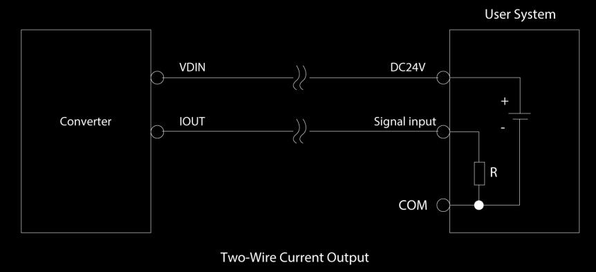
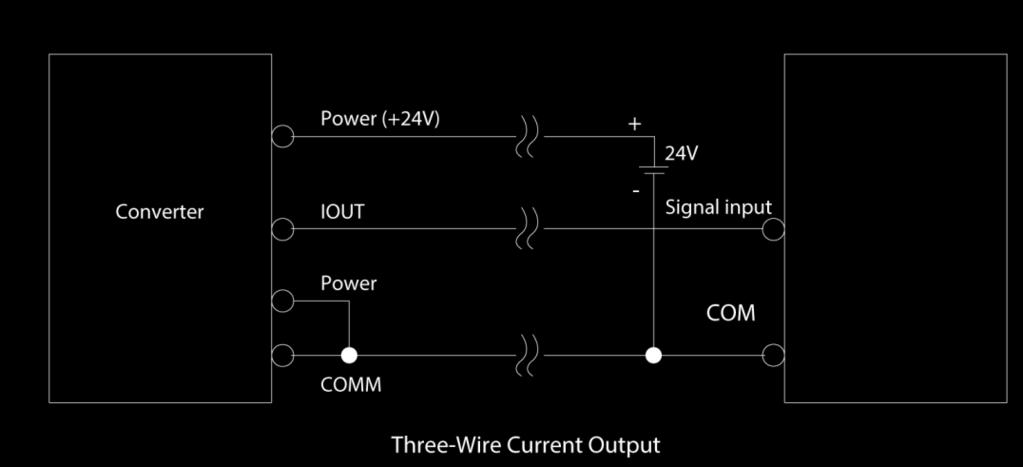
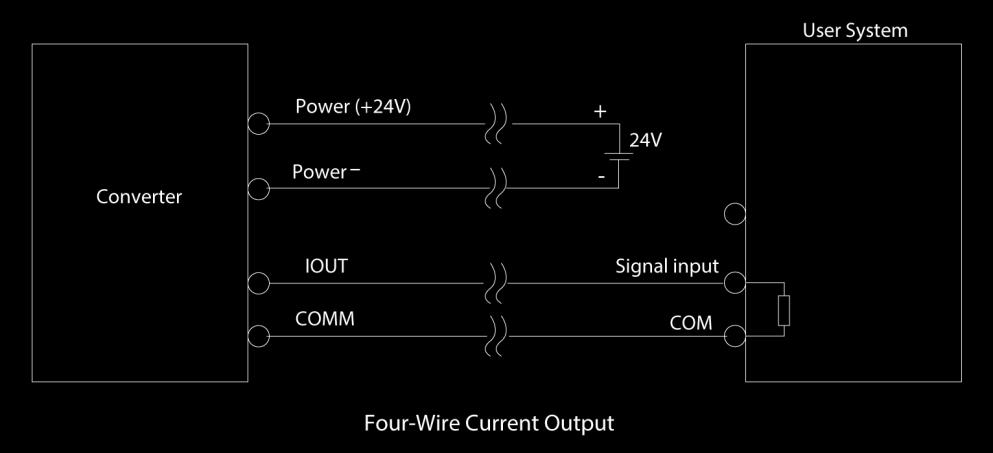
27 4.6.3 Transmitter Connection of Current Output 25

28 5 Operation This section covers operation techniques and guidelines. 5.1 Key and Display 1. Direct mount transmitter keys and LCD screen display 5.2 Parameter Setting CAUTION Make sure the sensor connected to the earth Make sure the liquid is still when regulating zero of the instrument The electrode and the liquid should be in continuous contact for about 48 hours 26
29 5.2.1 Keys Function Keys function in self- testing way Down key Up key Enter key Compound & Enter Under measurement status, adjustment of the LCD contract Selecting displayed data in lower lines in turn Selecting displayed data in higher lines in turn Press it to come into the interface measuring To enter parameter setting Push Down & Compound or Up & Compound Push Down & Compound or Up & Compound Down key Up key Shift & Down Shift & Up Enter key Subtract 1 from the number above cursor Plus 1 to the number above cursor To shift cursor to left To shift cursor to right To enter or exit the submenu; pressure for more than 2s to exit to measuring status NOTE When using the Compound key, you should press Compound key and Up or Down key both. To select the zero correction about the flow directly, use + or - to move the cursor and use Down or Up to Switch. To set or correct working parameters, the converter should be running in Parameters Setting Way instead of Measuring Status. In Measuring Status, press Compound + Enter keys getting to the select of parameter and transfer password (0000), and then correct the password with one of the new passwords that are provided by manufacturer. Finally, press the Compound + Enter keys to work in Parameters Setting Way. There are 6 Passwords in design and among them 4 for deferent operators in secret and 2 are fixed passwords for system operation. 27
30 5.2.2 Keys for Selecting Menu Press Compound + Enter keys to select menu. Press Up or Down keys to select the parameters. Code Function Notes 1 Parameters Set Select this function; It can enter the picture of parameter 2 Clr Total Rec Select this function; It can be gross reset operation 3 Fact Modif Rec Select this function, It can be check the factors modif record Parameter Setting Press Compound + Enter key, it displays Parameters Set function. Input password. Press Compound + Enter key. This function lets the user access Parameters Setting status. Clr Total Rec Press Compound + Enter keys to select the parameter, then press Up key to Clr Total Rec. Input the password. When the password is set to 00000, this function is done; the gross is 0 in the instrument. Fact Modif Rec To press Compound + Enter keys getting to the select of parameter, then press Up key to Fact Modif Rec. Menu There are 46 parameters of, user can set every parameter. The List of Parameters is shown below: 28
31 5.2.3 Menu There are 46 parameters of, user can set every parameter. The list of parameters is as shown below: Code Parameter Setting Grades Range 1 Language Select 2 English 2 Comm. Address Set Count 2 0 to 99 3 Baud Rate Select to Sensor Size Select 2 5 Flow Unit Select 2 l/h, l/m, l/s, m 3 /h, m 3 /m, m 3 /s 6 Flow Range Set Count 2 0 to Flow Rspns Select 2 1 to 50 8 Filt Factor Select 2 0/10/15/30/60/90/120/1 50/180/240 9 Flow Direct Select 2 Plus/ Reverse 10 Flow Zero Set Count 2 0 to ± Flow Cutoff Set Count 2 0 to % 12 Cutoff Ena Select 2 Enable/Disable 13 Total Unit Select m 3 to 1m 3, 0.001l to 1l 14 SegmaN Ena Select 2 Enable/Disable 15 Analog Type Select 2 0 to 10mA /4 to 20mA 16 Pulse Type Select 2 Freque / Pulse 17 Pulse Fact Select m 3 to 1m 3, 0.001l to 1l 18 Freque Max Select 2 1 to 5999 HZ 19 Mtsnsr Ena Select 2 Enable/Disable 20 Mtsnsr Trip Set Count % 21 Alm Hi Ena Select 2 Enable/Disable 22 Alm Hi Val Set Count to % 23 Alm Lo Ena Select 2 Enable/Disable 24 Alm Lo Val Set Count to % 25 Sys Alm Ena Select 2 Enable/Disable 26 Clr Sum Key Set Count 3 0 to Snsr Code1 User Set 4 Finished Y/M 28 Snsr Code2 User Set 4 Product number 29 Field Type Select 4 Type1,2,3 30 Sensor Fact Set Count to FwdTotal Lo Correctable to
32 32 FwdTotal Hi Correctable to RevTotal Lo Correctable to RevTotal Hi Correctable to PlsntLmtEna Select 3 Enable/Disable 36 PlsntLmtVal Select to 0.800m/s 37 Plsnt Delay Select to 2500ms 38 Pass Word 1 User Correct to Pass Word 2 User Correct to Pass Word 3 User Correct to Pass Word 4 User Correct to Analog Zero Set Count to Anlg Range Set Count to Meter Fact Set count to MeterCode 1 Factory Set 6 Finished Y/M 46 MeterCode 2 Factory Set 6 Product Serial No 30
33 Parameters of converters can decide the running status, process and output ways as well as state of output. Correct option and setting of parameters can keep the converters running optimally and get higher accuracies of output bother in display and in measurement. There are 6 grades of passwords for setting parameters function. Grades 1 to grade 5 of passwords are for users and grade 6 of password is for manufacturer. Users can reset their passwords of grades 1 to 4 in grade 5. Users can check converters parameters in any grade of password. However, if users want to change parameters of converters, deferent grade of parameters have to be used by the users. Grade 1 of password (set by manufacturer as 00521): Users can only read parameter. Grade 2 of password (set by manufacturer as 03210): Users can change 1 to 25 parameters. Grade 3 of password (set by manufacturer as 06108): Users can change 1 to 26 and 35 to 37 parameters. Grade 4 of password (Please contact Tek-Trol for this password if you need): Users can change 1 to 30 and 35 to 37 parameters. Grade 5 of password (Fixed): Users can change 1 to 46 parameters. Password Grade 5 can be set by skilled users. Grade 4 is mainly used for resetting total volume in password. Grades 1 to 3 can be set by anyone. NOTE Grade 4 is mainly used for resetting total volume in password. Grades 1 to 3 can be set by anyone. 31
34 6 Troubleshooting This section provides troubleshooting techniques for most common operating problems. 6.1 No Display 1. Check the power supply connection 2. Check the power fuse for faults 3. Check the contrast of LCD and adjust 6.2 Exciting Alarm 1. Check the connection of the exciting cables 2. Check the total resistance of sensor s exciting coil resistances (less than 150Ω) 3. If first and second points are OK, then the converter is faulty 6.3 Empty Pipe Alarm If measured fluid full of testing pipe of sensor: 1. Short circuit three connectors SIG 1, SIG 2, SGND of converter; if no Empty Alarm is displayed then the converter works. In this case, it is possible that the conductivity of measured fluid may be limited or the empty threshold of the empty pipe and the range of the empty pipe are incorrectly set 2. Check if the signal cable is OK 3. Check if the electro-poles are OK or not 4. Let the flow be zero, then the displayed conductivity should be less than 100% 5. Resistances of SIG1 to SGND and SIG2 to SGND are all less than 50kΩ (conductivity of water) during measurement operation. (It is better to test the resistances by means of multi-meter with pointer to see the charging process well 6.4 Measure Flow Disallow If measured fluid full of testing pipe of sensor, check if the signal cable is OK 32
35 TEKMATION LLC reserves the right to change the designs and/or materials of its products without notice. The contents of this publication are the property of TEKMATION and cannot be reproduced by any other party without written permission. All rights reserved. Copyright 2016 TEKMATION LLC TEKMATION LLC DOC#TEK/AK/MNL/IM-1400A/0218/B Tek-Trol is a fully owned subsidiary of TEKMATION LLC. We offer our customers a comprehensive range of products and solutions for process, power and oil & gas industries. Tek-Trol provides process measurement and control products for Flow, Level, Temperature & Pressure Measurement, Control Valves & Analyzer systems. We are present in 15 locations globally and are known for our knowledge, innovative solutions, reliable products and global presence. Tek-Trol LLC 796 Tek Drive Crystal Lake, IL USA Tel.: , Fax: tektrol@tek-trol.com Flow Level Temperature Pressure Valves Analyzers Accessories TekValSys
Electromagnetic Flowmeter. Instruction Manual
 TEK-FLUX 1400A Electromagnetic Flowmeter Instruction Manual Document Number: IM-1400A NOTICE Read this manual before working with the product. For personal and system safety, and for optimum product performance,
Ambient Conditions. Operating Conditions. Pressure
 Temperature Relative Humidity -20 C +75 C 0% 100 RH to 65 C non condensing 86 106 bar 4.0MPa (DN10 DN80) 1.6MPa (DN100 DN150) 1.0MPa (DN200 DN1000) Remote version < 80 C (rubber coating) Compact version
OPERATING INSTRUCTIONS
 OPERATING INSTRUCTIONS MAGFLO MMFM MAGNETIC FLOW METER (877) 356-5463 (p) 330-331-7331 (f) 330-331-7172 www.flo-corp.com 2017 FLO-CORP REVA 1116 1 Introduction Please read carefully! No liability can be
OPTIFLUX 5000 Technical Datasheet
 OPTIFLUX 5000 Technical Datasheet Electromagnetic flowmeter in flanged version Exceptional long-term stability and accuracy For highly aggressive and abrasive fluids Fully vacuum-resistant with high-tech
www. otech.com.sg EFS801 ELECTROMAGNETIC FLOWMETER
 www. otech.com.sg EFS801 ELECTROMAGNETIC FLOWMETER 1 www. otech.com.sg EFS801 - CFT181/RFT201 ELECTROMAGNETIC FLOWMETER Accurate, Reliable and Stable Flow Measurement. Measuring Principle The measuring
KFL-DC Serials Electromagnetic Flowmeters. User Manual
 KFL-DC Serials Electromagnetic Flowmeters User Manual s CONTENTS 1. Profile 1 2. Structure and Operating Principle 1 3. Specification 2 4. Model and Suffix Code 5 5. Material Selection. 6 6. Dimensions...6
OPTIFLUX 5000 Technical Datasheet
 OPTIFLUX 5000 Technical Datasheet Electromagnetic flowmeter in flanged version Exceptional long-term stability and accuracy For highly aggressive and abrasive fluids Fully vacuum-resistant with high-tech
WATERFLUX 3000 Quick Start
 WATERFLUX 3000 Quick Start Electromagnetic flow sensor The documentation is only complete when used in combination with the relevant documentation for the signal converter. KROHNE CONTENTS WATERFLUX 3000
WATERFLUX 3000 Quick Start
 WATERFLUX 3000 Quick Start Electromagnetic flowmeter The documentation is only complete when used in combination with the relevant documentation for the signal converter. KROHNE CONTENTS WATERFLUX 3000
Model TYC Electromagnetic Flowmeter. TYC Electromagnetic Flowmeter is applied to measure the volumetric flow of
 General Specifications Model TYC Electromagnetic Flowmeter TYC-Electromagnetic Flowmeter was developed based on principle of electromagnetic induction, i.e., when conductive liquid flows into measuring
TMF2011. Electromagnetic Flowmeter. Instruction Manual
 TMF2011 Electromagnetic Flowmeter Instruction Manual Table of contents 1- General 2- Installation 3- Basic Circuit 4- Specifications 5- Operation & Setup 6- Parameters Settings 7- Alarm Information 8-
Efcon Water. Installation & User Manual Electro Magnetic Flowmeter (EMF) Efcon Water compact Electro Magnetic Flowmeter (EMF) Manual Version UK
 Efcon Water compact Electro Magnetic Flowmeter (EMF) Manual Version UK") Efcon Water Installation & User Manual Electro Magnetic Flowmeter (EMF) Page 1 Table of content Page 1.1 General 3 1.2 Application area 4 1.3 Transportation 4 1.4 Principle of Operation 4 1.5 Product Description
Efcon Water Installation & User Manual Electro Magnetic Flowmeter (EMF) Page 1 Table of content Page 1.1 General 3 1.2 Application area 4 1.3 Transportation 4 1.4 Principle of Operation 4 1.5 Product Description
TEK-F LEX 4100A. Guided Wave Radar Level Transmitter. LEVEL. Technology Solutions
 Technology Solutions TEK-F LEX 4100A Guided Wave Radar Level Transmitter LEVEL www.tek-trol.com Flow Level Temperature Pressure Valves Analyzers Accessories TekValSys Introduction Featuring TDR (Time Domain
Electro-Magnetic Flowmeters COPA-XE
 Data Sheet Electro-Magnetic Flowmeters COPA-XE 10DX4311 Flowmeter system utilizes a smart microprocessor converter System accuracy of ± 0.5% of rate Field configurable via integral pushbuttons, eliminates
SITRANS F flowmeters. SITRANS F System information MAGFLO electromagnetic flowmeters 4/9
 Overview MAGFLO family MAGFLO electromagnetic are designed for measuring the flow of electrically conductive mediums. The patented MAGFLO Verificator guarantees accurate measurement and simple verification.
SITRANS F flowmeters SITRANS F M. Transmitter Transmag 2 with sensor 911/E 4/77. Overview
 Overview Design The complete flowmeter consists of a flow sensor and an associated transmitter from the Transmag 2 for pulsed alternating field. These are available as remote and compact versions ( 911/E
OPTIFLUX 1000 Technical Datasheet
 OPTIFLUX 1000 Technical Datasheet Electromagnetic flow sensor in sandwich design Lightweight and compact Excellent price performance ratio Quick and easy to install The documentation is only complete when
SITRANS F flowmeters. SITRANS F M System information MAGFLO electromagnetic flowmeters. 4/18 Siemens FI
 Function All are based on Faraday s law of induction: U M = B v d k U M = Measured voltage induced in the medium perpendicular to the magnetic field and the flow direction. The voltage is tapped at two
Electromagnetic Flow Transmitter
 Electromagnetic Flow Transmitter Sensor in solid state technology Working as a transmitter and/or as an On/Off controller Automatic-calibration of full scale: Teach-In Clean in place (CIP) Type can be
TIDALFLUX 2300 F Technical Datasheet
 Technical Datasheet Electromagnetic flow sensor for partially filled pipes Measurement in partially filled pipes up to DN1600 / 64" Patented, non-contact level measurement Measurement possible down to
TEK-TEMP 2100A. Explosion-Proof Temperature Transmitter. TEMPERATURE. Technology Solutions
 Technology Solutions TEK-TEMP 2100A Explosion-Proof Temperature Transmitter TEMPERATURE www.tek-trol.com Flow Level Temperature Pressure Valves Analyzers Accessories TekValSys Introduction Tek-Trol s Explosion-Proof
Magnetic-inductive flow meter. PITe / UMF2. Technical Datasheet. Maintenance-free Nearly no pressure drop Robust design Easy installation and start-up
 Magnetic-inductive flow meter Technical Datasheet PITe / UMF2 Maintenance-free Nearly no pressure drop Robust design Easy installation and start-up Subject to change without notice 1 Function An electrically
BATCHFLUX 5500 C Technical Datasheet
 BATCHFLUX 5500 C Technical Datasheet Electromagnetic flowmeter for volumetric filling machines High-stability ceramic measuring tube, therefore extremely long-term stability Optimum hygienic design Only
USER MANUAL Electromagnetic Flowmeter. Pressure Differential Relay Switch + Gauge
 USER MANUAL 1000 Electromagnetic Flowmeter Pressure Differential Relay Switch + Gauge Read the user's manual carefully before starting to use the unit or software. Producer reserves the right to implement
KMS502F. ManuFlo Page 1 MANU ELECTRONICS PTY LTD Flow Measurement Products. Electromagnetic Flanged Flowmeters FEATURES: (sizes: 25mm to 200mm)
") KMS502F Electromagnetic Flanged Flowmeters (sizes: 25mm to 200mm) FEATURES: For all your water applications including batching. Flanged connection suites ANSI 150lb flanges. Unsurpassed accuracy to ±0.5%
KMS502F Electromagnetic Flanged Flowmeters (sizes: 25mm to 200mm) FEATURES: For all your water applications including batching. Flanged connection suites ANSI 150lb flanges. Unsurpassed accuracy to ±0.5%
FLOW SWITCH 600 Series Velocity Flow Sensor. Instruction Manual
 SWITCH 600 Series Velocity Flow Sensor Instruction Manual Ultrasonic Velocity Sensor using Doppler Technology Model: FS-600 Manual Release Date: November, 2009 ECHO Process Instrumentation, Inc. CONTENTS
Flow Technologies Overview. For internal use only / Siemens AG All Rights Reserved.
 Flow Technologies Overview Mag Flow MAGFLO Program Siemens offers a comprehensive selection of electromagnetic flow meters Water & waste water Chemical Food & beverage Mining Aggregates Cement Pharmaceutical
User's Manual of KDLD. Electromagnetic Flow Meter
 开德仪表 Kaide Flow Instrument Accuracy and Attitude, Access to Customer. Kaifeng Kaide Flow Instrument Co., Ltd. No2. Indusrtial Road, Huanglong Industrial Park, Kaifeng County, Henan, China Tel: 86-378-3212788
BEIJING GALLOP HIGH&NEW TECH.CO.,LTD. CONTENTS 1. THE PRODUCT FUNCTION INTRODUCTION BASIC CIRCUIT OF CONVERTER... 4
 BEIJING GALLOP HIGH&NEW TECH.CO.,LTD. CONTENTS 1. THE PRODUCT FUNCTION INTRODUCTION... 1 1.1 BASIC FUNCTION... 1 1.2 ESPECIAL FUNCTION... 1 1.3 NORMAL OPERATING CONDITIONS... 2 1.4 TYPE OF CONNECTING WITH
Digital flow transmitter for continuous flow measurement
 Digital flow transmitter for continuous flow measurement Compact or remote version for DN 06 to 400, PN10 Shows both flow rate and volume (with two totalizers) Automatic-calibration: TEACH-IN Simulation:
EN-2018 MAGNETIC FLOW METERS
 EN-2018 MAGNETIC FLOW METERS www.meatest.com 1 MEASURING PRINCIPLE Having no moving or mechanical parts in the flow profile electromagnetic flow meters cause no pressure drop, are virtually maintenance
Magnetic Inductive Flow Sensor induq
 Operating manual (Translation) Operating manual... page 1-16 Magnetic Inductive Flow Sensor induq Series VMZ SIKA Ba_VMZ_en 10/2014. Please keep this operating manual for future reference. If the device
KMS101W. ManuFlo Page 1 MANU ELECTRONICS PTY LTD Flow Measurement Products. Electromagnetic Wafer Flowmeters with S100 display
 KMS101W Electromagnetic Wafer Flowmeters with S100 display ideal as resettable/batching meter (sizes: 15mm to 150mm) 0BFEATURES For ADMIXTURE Batching, Shotcrete, Mild-Recycled Water & Selected Chemical
KMS305W. ManuFlo Page 1 MANU ELECTRONICS PTY LTD Flow Measurement Products. Electromagnetic Wafer Flowmeters with S300 display
 Electromagnetic Wafer Flowmeters with S300 display for corrosive chemicals/acids & slurries (sizes: 2.5mm to 100mm) 0BFEATURES: For aggressive chemicals, slurries, oxides, grouts & dosing applications
FMG90 Series Electromagnetic Flow Meter
 . FMG90 Series Electromagnetic Flow Meter - 2 - Series FMG90 Series FMG90 Table of contents page 0 About this operating manual... 4 1 Device description... 5 1.1 Delivery, unpacking and accessories...
OPTISONIC Ultrasonic flowmeter for liquids in all industrial applications
 OPTISONIC 3400 Ultrasonic flowmeter for liquids in all industrial applications Measurement of conductive and non-conductive, low and high viscous liquids, from -200 to +250 C / -328 to +482 F medium temperature
FLOMID FX Electromagnetic Flowmeter
 FLOMID FX Electromagnetic Flowmeter Working pressure manufacturing according to PED 97/23/CE (Lloyd s Register Certificate Nº 031) Introduction Modular design in two versions: Compact, sensor and electronics
Model Sono-Trak Transit Time
 Model Sono-Trak Transit Time Ultrasonic Flow Meter Engineered for performance excellence, the Sono-Trak Transit Time ultrasonic meter combines non-invasive, bi-directional measurement with advanced ultrasonic
WATERFLUX 3070 Technical Datasheet
 WATERFLUX 3070 Technical Datasheet Engineered and manufactured for the water and wastewater industry Highly accurate measurement with extremely short in- and outlet lengths Battery operated, stand alone
Advanced instrumentation solutions crafted with highest precision
 www.adeptfluidyne.com Advanced instrumentation solutions crafted with highest precision perpendicular to both the liquid flow direction and the electromagnetic field direction. The voltage sensed by the
F-3200 SERIES Inline Electromagnetic Flow Meter Wiring Instructions
 F-3200 SERIES Inline Electromagnetic Flow Meter Wiring Instructions ELECTRICAL INSTALLATION Input Power Requirements F-3000 Electromagnetic Flow Meters equipped with standard transmitters are available
UFM 800 W, C Ultrasonic flowmeter for water and wastewater
 KROHNE 08/2000 7.02343.21.00 GR/PRINTO, C Ultrasonic flowmeter for water and wastewater...with weld-in sensors for metal pipelines...withbuilt-on or built-in sensors for open channels Variable area flowmeters
MP Series Radar Transmitter Installation & Operation Manual
 IOM MP Series Radar Transmitter Installation & Operation Manual MP Series Radar Transmitter Installation & Operation Manual CONTENTS I. HANDLING AND STORAGE... 1 Inspection and Handling Disposal and Recycling
L-mag Electromagnetic Flowmeter Converter. User s Manual. L-mag 511 Series
 L-mag Electromagnetic Flowmeter Converter User s Manual L-mag 511 Series April 2017 CONTENTS 1. THE PRODUCT FUNCTION INTRODUCTION... 1 1.1 BASIC FUNCTION...1 1.2 ESPECIAL FUNCTION...1 1.3 NORMAL OPERATING
INSERTION paddle wheel flowmeter for continuous flow measurement
 INSERTION paddle wheel flowmeter for continuous flow measurement Economic integration in pipe systems without any additional piping 3-wire frequency pulse version to directly interface with PLC s (both
BATCHFLUX 5500 C Handbook
 BATCHFLUX 5500 C Handbook Electromagnetic flowmeter for volumetric filling machines KROHNE : IMPRINT ::::::::::::::::::::::::::::::::::::::: All rights reserved. It is prohibited to reproduce this documentation,
Technical Information Proline Promag 10P
 TI00094D/06/EN/13.17 71385977 Products Solutions Services Technical Information Electromagnetic flowmeter Flow measurement of liquids in chemical or process applications Application Electromagnetic flowmeter
Flow Switch - 2 programmable thresholds. Stand Alone (Battery) - Battery powered, - 2 totalizers display, - Local flow display,
 - Battery powered, - 2 totalizers display, - Local flow display,") DN 15 - DN 50; PN Advantages / Benefits Easy System integration by Easy LINK provides low cost of ownership Easy commissioning due to multi-language, menu-guided operation TEACH-IN: automatic calibration
DN 15 - DN 50; PN Advantages / Benefits Easy System integration by Easy LINK provides low cost of ownership Easy commissioning due to multi-language, menu-guided operation TEACH-IN: automatic calibration
MaxxFlow HTC Flow Measurement for Dry Bulk Solids
 EN MaxxFlow HTC Flow Measurement for Dry Bulk Solids Manufactured by Product Information www.onthelevel.com MaxxFlow HTC MaxxFlow HTC MaxxFlow HTC Product Information Use The MaxxFlow HTC was developed
FMG70B Series Magnetic Inductive Flow Sensor
 . FMG70B Series Magnetic Inductive Flow Sensor - 2 - M-5575/0416 Table of contents page 0 About this operating manual...4 1 Device description...5 1.1 Delivery, unpacking and accessories...5 1.2 Intended
Marketing Communications
 More than precise measuring New instrument diagnostic concepts offer interesting approaches for process optimization Due to high reliability and accuracy, low maintenance requirements, low power consumption
Smart Electromagnetic Flowmeter Open channel Flowmeter Detector
 No. SS2-MGN200-0200 MagneW3000 PLUS Smart Electromagnetic Flowmeter Open channel Flowmeter Detector Model NNK150/951 OVERVIEW The MagneW3000 PLUS Electromagnetic Flowmeter is submersible type of flowmeter
Magnetic-Inductive flow Meter fmi
 1 Product information fmi-c, fmi-r f o o d P H A R M A Magnetic-Inductive flow Meter fmi Application/Specified usage Magnetic-inductive flowmeter for the measurement of flow rate and volume in food and
Magnetic Flowmeter Systems
 Series 8700 Magnetic Flowmeter Systems THE 8700 SERIES... Model 8712 C/U - Easiest to use local operator interface and works with any manufacturer s flowtubes Model 8712H/8707 High-Signal System - Pulsed
Digital flowmeter for continuous flow measurement
 8025 Flowmeter INSERTION Digital flowmeter for continuous flow measurement Compact or remote version for DN06 to DN400, PN10 Displays both flow rate and volume (with two totalizers) On site calibration
Type PLC Fitting. Valve for Continuous control. Diaphragm valve. Output
 Digital Inductive conductivity transmitter Optimal solution for conductivity measurements in difficult fluids (polluted, dirty,...) PEEK/PPA version for CIP applications Large range of process connections
Earth Fault Indicator EFI-BLZ-50 User Manual
 Earth Fault Indicator EFI-BLZ-50 User Manual CONTENTS SAFETY NOTICE.................................................................................... 3 1 OVERVIEW......................................................................................
Proven Measurement for A World of Applications
 Proven Measurement for A World of Applications Building on Experience. Niagara Meters is a flow meter company representing a complete line of flow meters manufactured by Venture Measurement Co., LLC in
Digital flowmeter for continuous flow measurement
 8025 Flowmeter INSERTION Digital flowmeter for continuous flow measurement Compact or remote version for DN06 to DN400, PN10 Displays both flow rate and volume (with two totalizers) On site calibration
E l e c t r o m a g n e t i c f l o w m e t e r s
 E l e c t r o m a g n e t i c f l o w m e t e r s P r o v e n A N D R e l i a b l e F l o w M e a s u r e m e n t 2 MJK MagFlux flow meters combine high accuracy, stability and low maintenance. Without
Signal converter for electromagnetic flowmeters
 Quick Start Signal converter for electromagnetic flowmeters Electronic revision: ER 3.0.xx The documentation is only complete when used in combination with the relevant documentation for the flow sensor.
Flow Measurement SITRANS F M
 Overview Mode of operation The flow measuring principle is based on Faraday s law of electromagnetic induction according to which the sensor converts the flow into an electrical voltage proportional to
ELECTROMAGNETIC FLOW METER AFLOWT MF
 ELECTROMAGNETIC FLOW METER AFLOWT MF OPERATION MANUAL 9001:2008 Saint-Petersburg, Russia * * * VZLJOT JSC quality management system is certified to ISO 9001:2008 * * * Vzljot JSC Postal address: Masterskaya
WATER MADE EASY MARINE ENERGY MUNICIPAL INDUSTRIAL
 MicroChem Water Analysis System The MicroChem is a versatile multi-parameter instrument capable of being configured as a transmitter or PID controller. Specifically designed for drinking and wastewater
Field IT Electro-Magnetic Flowmeters Mini-Mag with integral XE converter
 Data Sheet D-FMP-10D1475W-Y_4 Field IT Electro-Magnetic Flowmeters Mini-Mag with integral XE converter 10D1475W/Y Flowmeter Systems utilizes a smart microprocessor converter. System accuracy of ±0.5% of
Digital flow ELEMENT transmitter for continuous flow measurement
 ELEMENT Transmitter Digital flow ELEMENT transmitter for continuous flow measurement Type can be combined with... PN10, DN15 to DN400 fluidic process connection Programmable outputs : one or two transistor
IFC 010 Signal Converter
 KROHNE 04/2003 7.02347.22.00 GR Signal Converter for electromagnetic flowmeters Easy to install Low-cost signal converter, measuring error < 0.5% of the measured value Easy user-friendly operation Self-monitoring
The transducer component converts the measured signal and displays the actual value.
 Digital inductive conductivity transmitter System Integration Provides low Total Cost of Ownership PEEK/PPA version for CIP applications TEACH IN and SIMULATION Function Approval PVDF Version PEEK Version
Mobrey Ultrasonic. MSP422, MSP400RH, and MSP900GH Level Transmitters. Product Data Sheet February 2015 IP2045, Rev EA
 Mobrey Ultrasonic Product Data Sheet February 215 IP245, Rev EA MSP422, MSP4RH, and MSP9GH Level Transmitters Non-contacting measurement with no moving parts Integral LCD and push-buttons as standard for
Target disk flowmeters Series DP Metallic flowmeter for liquids and gases
 Target disk flowmeters Series DP Metallic flowmeter for liquids and gases Metallic, simple and robust construction Available for all flow directions Suitable for extreme pressure and temperature conditions
INLINE flowmeter for continuous flow measurement
 INLINE flowmeter for continuous flow measurement Economic integration in pipe systems without any additional piping 3-wire frequency pulse version to directly interface with PLC s (both PNP and NPN) Connection
Electromagnetic flowmeters and switches DWM 1000/2000
 KROHNE 10/2000 D 20 DW10 02 E GR Electromagnetic flowmeters and switches DWM 1000/2000 Variable area flowmeters Vortex flowmeters Flow controllers Electromagnetic flowmeters Ultrasonic flowmeters Mass
INTRODUCING SOME GREAT NEW PRODUCTS FROM OUR DWYER INSTRUMENTS RANGE:
 Unit 1 / 14 Biscayne Way Jandakot WA 6104 P.O. Box 3232, Success WA 6964 Tel: (08) 9414 7666 Fax: (08) 9414 7677 Email: dg@dginstruments.com.au Website: www.dginstruments.com.au A.B.N: 59 113 005 959 DATE:
Series 500. Owner s Manual. Analog Transmitters by Data Industrial. Data Industrial. Data Industrial 2/95 PN 72806
 Series 500 Analog Transmitters by Data Industrial Data Industrial Owner s Manual Data Industrial 2/95 PN 72806 Table of Contents Introduction... 1 4-20 ma Loop Supply Requirements... 2 Installation...
MODEL AT-10 ANALOG TRANSMITTER
 MODEL AT-10 ANALOG TRANSMITTER INSTALLATION & OPERATING MANUAL Industrial Weighing Systems 9 Richmond Street Picton, Ontario K0K 2T0 Phone: 613-921-0397 Fax: 613-476-5293 Web: www.iwsystems.ca info@iwsystems.ca
INLINE flowmeter for continuous flow measurement
 INLINE flowmeter for continuous flow measurement Economic integration in pipe systems without any additional piping 3-wire frequency pulse version to directly interface with PLC s (both PNP and NPN) Connection
OPTIFLUX 1000 Handbook
 OPTIFLUX 1000 Handbook Electromagnetic flow sensor in sandwich design The documentation is only complete when used in combination with the relevant documentation for the signal converter. KROHNE : IMPRINT
S103C ELECTROMAGNETIC FLOW METERS. Main application fields MOUNTING
 ELECTROMAGNETIC FLOW METERS The electromagnetic flow meter is used to measure the flow rate of conductive fluids and waste water. The measurement is independent of the density, viscosity, temperature and
ITP14. Universal process indicator. User guide
 ITP14 Universal process indicator User guide ITP14_2018.05_0279_EN All rights reserved Subject to technical changes and misprints akytec GmbH Vahrenwalder Str. 269 A 30179 Hannover Germany Tel.: +49 (0)
BATCHFLUX and BATCHCONTROL
 KROHNE 04/2001 D 31 BATC 02 E GR/PRINTO BATCHFLUX and volumetric batching and dosing with electromagnetic flowmeters A new era in volumetric batching!!! Optimum sanitary design Ceramic measuring tube Only
User s Manual CM2-MGR nd edition
 MagneW 3000 Electromagnetic Flowmeter Hyper-Fill Model: MGR13C (Converter) MGR11U (Detector) User s Manual CM2-MGR100-2001 2nd edition Copyright, Notices and Trademarks 2005-2012 Azbil Corporation All
INLINE flowmeter for continuous flow measurement
 INLINE flowmeter for continuous flow measurement Economic integration in pipe systems without any additional piping 3-wire frequency pulse version to directly interface with PLC s (both PNP and NPN) Connection
SI-125 Power Amplifier Manual 6205 Kestrel Road; Mississauga, Ontario; Canada; L5T 2A1 November 2016, Rev 0.5
 SI-125 Power Amplifier Manual 6205 Kestrel Road; Mississauga, Ontario; Canada; L5T 2A1 November 2016, Rev 0.5 Phone: (905) 564-0801 Fax: (905) 564-0806 www.telecor.com E:\T2-108\T2-M108-ABC\T2-M108-B.doc/AD
Electromagnetic Flow Measuring System Two-wire, loop-powered PROline promag 23 P
 Technical Information TI 049D/06/en 50097005 Electromagnetic Flow Measuring System Two-wire, loop-powered PROline promag 23 P Flow rate measurement in chemical or process applications Features and benefits
RUNYI GROUP AJ FLOW TOTALIZER. Features
 AJ FLOW TOTALIZER Features Suitable for flow (Heat) displaying, calculating and controlling of all kinds of liquids, single or mixed gases and vapor. Input multiple flow sensor signals (Such as VSF, Turbine,
Electromagnetic Flowmeter Comet F
 Electromagnetic Flowmeter Comet F - Exact measurements - Comfortable calibration with PC - No setup elements - No pressure loss - Periodic cleaning of electrodes - Data backup during power failure - Communication
RCM DIRECT READING FLOWMETER
 RCM DIRECT READING FLOWMETER Flow Pressure Level Temperature measurement monitoring control Special Features Compact Design Easy to Install For Horizontal or Vertical Pipes Rugged Construction Accuracy:
Electromagnetic Flow Measuring System promag 35
 Technical Information TI 035D/06/en No. 50075884 Electromagnetic Flow Measuring System promag 35 Applications Promag 35 S solves complex flow problems and is used to measure fluids with a high solids content,
Capacitive level meters CLM 40 INSTRUCTIONS MANUAL. průmyslová elektronika
 průmyslová elektronika INSTRUCTIONS MANUAL Capacitive level meters CLM 40 Before level meters usage please read instructions in this service manual and keep it for further use. Service manual is for all
Smart Electromagnetic Flowmeter Open channel Flowmeter Detector
 Magne3000 PLUS Smart Electromagnetic Flowmeter Open channel Flowmeter Detector Model NNK150/951 OVERVIE The Magne3000 PLUS Electromagnetic Flowmeter is submersible type of flowmeter mainly used for flow
B850 Boiler House Energy Monitor
 Local regulations may restrict the use of this product to below the conditions quoted. In the interests of development and improvement of the product, we reserve the right to change the specification without
PhD Inline Vortex. Performance Specifications Accuracy. Operating Specifications
 Description The Vortex PhD vortex shedding flowmeter measures process fluid flow by detecting the frequency at which vortices are shed from an obstruction in the process fluid line (the bluff body). A
Magnetic Inductive Flow Sensor
 Operating manual (Translation) Operating manual... page 1-20 Magnetic Inductive Flow Sensor Series VMZ Types VMZ 030 VMZ 081 VMZ 082 VMZ 153 VMZ 204 VMZ 205 VMZ 256 SIKA Ba_VMZ_en 11/2017. Please keep
Phase-sequence Phase-loss Relay
 Phase-sequence Phase-loss Relay K8AB-PH Three-phase Phase-sequence Phase-loss Relay Using Voltage Detection Method Prevents reverse motor rotation due to incorrect wiring. Distinguishes between positive
Installation & Operation Manual
 Magnetoflow Mag Meter Sanitary Meter with Model Primo 3.1 Installation & Operation Manual BadgerMeter,Inc. IOM-104-02 53400-104 3-09 SCOPE OF THIS MANUAL This manual contains information concerning the
ABB flowmeter technology FSM4000 AC-excited magmeter
 White paper ABB flowmeter technology FSM4000 AC-excited magmeter Innovative AC-excited magmeter benefits pulp and paper operations by Greg Livelli, ABB Measurement Products Design innovations in AC-excited
Instruction MI December Magnetic Flow System
 Instruction MI 021-138 December 2015 Magnetic Flow System 2800 Series Flowtubes with an 896 or an E96 Transmitter Fault Location Guide Contents Contents...3 Figures...5 Tables...6 Introduction...7 Reference
Ricochet Alphasonic Level Transmitter Model LA15/20 Owner s Manual
 Warranty, Service & Repair To register your product with the manufacturer, fill out the enclosed warranty card and return it immediately to: Flowline Inc. 500 Humbolt Street Los Alamitos, CA 9. If for
Target disk flowmeter for liquids and gases
 Target disk flowmeter for liquids and gases Metallic, simple and robust construction Available for all flow directions Suitable for extreme pressure and temperature conditions Low pressure drop Straight
+GF+ SIGNET Temperature Transmitter Instructions
 GF SIGNET 80- Temperature Transmitter Instructions ENGLISH -80.090- B-/00 English CAUTION! Remove power to unit before wiring input and output connections. Follow instructions carefully to avoid personal