CTU Presents. Short Vertical RX Antennas and Feedline Chokes by Greg Ordy, W8WWV
|
|
|
- Lynette Clark
- 5 years ago
- Views:
Transcription


1 CTU Presents Short Vertical RX Antennas and Feedline Chokes by Greg Ordy, W8WWV
2 Introduction Antenna arrays consisting of 2 or more vertical elements are one of the many alternatives used to improve lower HF band (e.g. AM, 160m, 80m) reception. Other common receiving antennas include: Beverage, K9AY, EWE, Flag, Pennant, etc, and arrays of those building blocks.
3 Introduction (2) Because the challenge to reception on the lower bands is usually overcoming noise with an improved signal to noise ratio, as opposed to simply higher gain, the directivity of the antenna is a key parameter. Arrays are a good solution that provides a more focused pattern a pattern with higher directivity.
4 Introduction (3) The omni directional vertical, as an array building block (element), has no inherent directional bias, and rotating the array electrically is straightforward (assuming a symmetric ground layout!). Since gain is not a critical parameter, receiving verticals are usually short (relative to the canonic ¼ wavelength) to simplify installation and reduce mutual coupling. Mutual coupling is the interaction (via reradiation) between nearby elements, and in receiving arrays (passive & active), the (unstated) assumption is that mutual coupling can be ignored. That is an important design simplification that is usually never true in transmitting arrays. Always be aware of when you can and cannot ignore it.

5 Typical Array Configuration outside inside... Phasing Box Ctrl. TLine Control Box The primary focus of this presentation is the vertical antenna portion of the array.
6 Vertical Types There are two types of verticals in common use in receiving arrays. Passive Active They are remarkably different in how we should think about them and use them.
7 Vertical Types (2) For both types, it is necessary for the correct operation of the phasing network that we supply signals on the transmission lines that are matched to the line Zo (often 75 Ohms). The lines are run flat. This demands that the elements produce Zo output. With transmit arrays, following the complex current through the feed system is essential because current flowing in an element produces radiation. Line usually never run flat. Since the elements in a receiving array produce Zo (e.g j 0) signals, it doesn t matter if we are talking about voltage or current downstream, since both are in phase, and simply have a ratio of 75. A voltage perspective is common. Another important array assumption is that each vertical produce the same signal level (magnitude and phase) when placed in the same RF field. They are the same and electrically identical. Our job at the antenna is to work hard to make them the same.
8 Passive Vertical Antennas Current Fed (fed at the current maximum), low impedance. Impedance matching is used to achieve Zo; LC, LR, LL, etc. It s common to talk about and create resonance (X = 0). Narrowband (Zo output for a small frequency range) Ground systems sink current, and along with the matching network components determine the element losses (and gain). Similar to transmit verticals in many ways, except for the fact that the short length reduces mutual coupling to a negligible level. Mutual coupling is almost always important in transmitting arrays and must be included in the phasing system design. Receiving arrays assume negligible mutual coupling and Zo input signals.
9 Active Vertical Antennas Voltage fed (fed at the voltage maximum), high impedance. Impedance matching is achieved by a high (~megaohm) input impedance active buffer that converts a voltage into a Zo impedance signal. The buffer requires a power supply, often via a Bias Tee. The high input impedance of the buffer implies that almost no current flows out of the antenna (in the perfect ( Z) world, none does). Ground systems provide a zero volt reference to the buffer. Almost no current flows in the ground system because of the high impedance buffer. Resonance (in the antenna) is not necessary for useful operation. Broadband (Zo impedance can be maintained for many MHz). Mutual coupling is even lower than in a passive vertical of the same length (antennas can be longer and closer together without trouble). Conceptually similar to a voltmeter (measure without loading down). The antenna can be considered to be a probe or sampler of the electromagnetic field passing by.
10 Comparing the Two Types 1.83 MHz Passive Active Current maximums will occur in the middle of a conductor, voltage maximums will occur at the ends. A high impedance connection is as good as an end (like an antenna trap, for example). It s as good as floating. From this point forward, the focus will be on the short active receiving antenna.
11 Plane Wave Modeling Antenna modeling in NEC uses Sources to excite the antenna at one or more points on Wires. Sources are complex, with a magnitude and phase, and are either voltage or current Sources. Patterns, gain, and other parameters, as well as Source impedance(s) are computed as a function of frequency. Although the perspective taken is largely that of transmission, a consequence of the antenna reciprocity theorem makes the results valid for reception (same pattern, same gain, etc).
12 Plane Wave Modeling (2) The NEC engine has always supported a second perspective. That perspective has the antenna stimulated by a plane wave that arrives from a specified direction, elevation, and polarization, with a specified field strength (V/m). (one ideal signal) This is an alternative to the usual Source excitation. The only modeling shell/gui that I am aware of that supports this feature is EZNEC/Pro. If you are willing to directly work with NEC card decks, plane wave modeling can be done in NEC-2.
13 Plane Wave Modeling (3) Transforms to Plane Wave V/m V =? Plane Wave modeling is very helpful in analyzing aspects of active high impedance antennas. (normal Source modeling is also needed (e.g. patterns)) A high value Load resistor can be inserted in place of the buffer. The complex voltage at the resistor terminals is the voltage that will be supplied to the buffer.
14 Example 1; 24 Vertical 24 tall, 1 OD, 1 mohm Load, wave 1 V/m, 20 deg. elevation. 50 KHz steps. Program flow: EZNEC/Pro -> LBDXView (5 th ed. ON4UN CD)

15 Example 2; Verticals 32 P = V 2 /R 2V = 4P = +6 db 16
16 Example 2; Analysis So long as you are operating below the resonance region, the antenna output voltage will be an approx. linear function of its length. V = L X Fs. Twice the length, twice the voltage, +6 db. Half the length, half the voltage, -6 db. While getting close to resonance increases the voltage output (gain), it will also increase the mutual coupling. Consider a typical Yagi with ~½ wavelength floating parasitic elements. It works because of mutual coupling. In an array, don t ever forget the importance of sameness. I try to keep individual errors under 1%.
17 Example 3; Antenna Diameter With a 24 length, I modeled 7 diameters: 1.0, 0.5, 0.25, 0.125, 0.05, 0.025, and At nonresonant lengths, diameter variations are not a large source of error. Acceptable error
18 Example 4; Mutual Impedance In this application, mutual coupling/impedance can be ignored so long as the complex voltage out of an antenna is due exclusively to the plane wave. No antenna sees another nearby antenna. Both magnitude and phase matter. As before, I like to keep the error under 1%. Consider two identical but nearby verticals. Their magnitudes should be the same, and the phase shifts should be due to the ground separation and arrival angles. When those conditions are not true, they are interacting, and the array performance will probably be compromised (not anticipated in the phasing box design). In this example, the arrival azimuth is end fire, elevation is 20 degrees. This example also gives us a chance to look at phase shifts as well as voltage magnitudes. Mutual coupling effects can also be determined in normal Source modeling as a shift away from self impedance.
19 Example 4 (2); Mutual Impedance Plane Wave deg mega Ohm Load resistor at the base of each vertical.
20 Example 4 (3); Mutual Impedance Voltage Magnitude comparison. Up through ~13 MHz, the pair of 24 verticals with 40 ground distance show little magnitude deviation. We could add the results of a single vertical to be 100% sure we aren t being influenced. (but we are not!) Coupling causes deviation from being the same
21 Example 4 (4); Mutual Impedance Voltage Phase comparison. The phase data follows a relative value convention in NEC, which can make it a little tricky to interpret. Let s subtract the two values to remove some confusion.
22 Example 4 (5); Mutual Impedance A little less confusing! At 1.85 and 3.7 MHz, the modeled phase shifts equal the computed. A deviation from a straight line is a sign of concern. Clearly something bad is happening near the ½ wavelength resonance. Degrees Two Vertical Normalized Phase Shift MHz MHz Frequency (MHz)
23 Example 4 (6); Mutual Impedance While it would always be best to model the layout and dimensions of a specific array to determine if there is a mutual impedance problem, I have modeled enough examples to suggest the following rule of thumb. So long as the verticals are no longer than 1/8 wavelength at the highest frequency of operation, you can put them as close together as you want and consider them to be independent with negligible coupling. For example, 31 feet to extend up to 4.0 MHz. This assumes the high impedance active end feed so that the element is effectively floating, and while current flows within it, no current flows out of it. We are simply sampling the end voltage, and the scattered energy is not enough to be detected.
24 Base Shunt Capacitance With a high impedance port, stray shunt (parallel) capacitance can be an impossible to avoid issue. It provides a sneak path around the buffer. The voltage can be dragged down, finding a preferred path to ground. Active verticals have at least two sources of stray capacitance. Buffer Circuitry and Packaging (~5 to 20 pf) Antenna Mount Construction (up to ~80 to 100 pf)


25 Base Shunt Capacitance (2)
26 Base Shunt Capacitance (3) 24 tall, 1 OD, 1 mohm Load, wave 1 V/m, 20 deg. elevation. 50 KHz steps. 0 pf 100 pf
27 Base Shunt Capacitance (4) Increasing the shunt capacitance lowers the ½ wavelength resonant frequency. The voltage output, where we care (1 4 MHz), for 100 pf, dropped by a factor of 2, or -6 db of gain. The problem is not so much the loss of gain, but rather trying to maintain sameness (1% errors) in the elements. For that reason, the verticals should be constructed as identically as possible to make the base capacitance the same, or as close as possible, for each vertical.
28 Series Inductance The response of the active antenna can be changed by adding a series base inductor. The ½ wavelength resonance is lowered in frequency. Somewhat dangerous in an array, since the gain tolerances will not be 0.1dB (1%) without work. (phase too) E.g.: 16 vertical, 100 uh. I really didn t believe a 20 db gain spike, so I needed to measure it. A 100 uh RF choke was used because it was convenient, and below self resonance. Good for making a narrower band vertical with a ton of gain. 10V = 100P = +20 db


29 Series Inductance (2) 16 Vertical Two 16 verticals with an A/B Switch With 100 uh ~ 20 db 6 MHz MHz MHz Sweep, Night (23:00 EDT)
 AM BCB 6 MHz 6")

30 Series Inductance (3) AM BCB 6 MHz 6 MHz MHz Sweep, Day (9:30 EDT)
31 Series Inductance (4) Larger inductance lowers the frequency but also narrows the response. Trade off length and inductance to achieve a desired response. Use in an array is problematic due to rapid rates of change in magnitude and phase near the peaks. The target has been to hold errors < 1%. Adding series inductance does not appear to change the mutual coupling level. If you want some real fun, move the location of the inductor further up! 200 uh 100 uh 50 uh 25 uh 10 uh 1 uh
32 The Role of Ground In the case of a high impedance voltage fed monopole, the role of ground is to provide a stable zero volt RF (local) reference. It is not the other half of the antenna, and not a point where we want to encourage RF current to flow. It is the other half of the buffer input. Low loss ground systems are not important. Any change in the reference point voltage will enter the buffer. Radials, ground rods, and mounting poles can all be used. What they need to be is stable, and not carry an RF voltage potential. Radials need not be long, but they should be symmetrical so as to not be acting like a net antenna. We want only the antenna to provide signal energy, not the ground reference system. V- 0V V+ 0V Monopole
33 The Role of Ground (2) Be sure to know how the transmission line to the phasing box is being treated, and that it is not acting like a single long antenna wire. V- 0V V+ 0V X One solution would be an RF choke on the line, or some other form of isolation. Another would be a very low impedance local ground so that any current on the line goes to ground with no voltage drop that would be seen by the buffer.
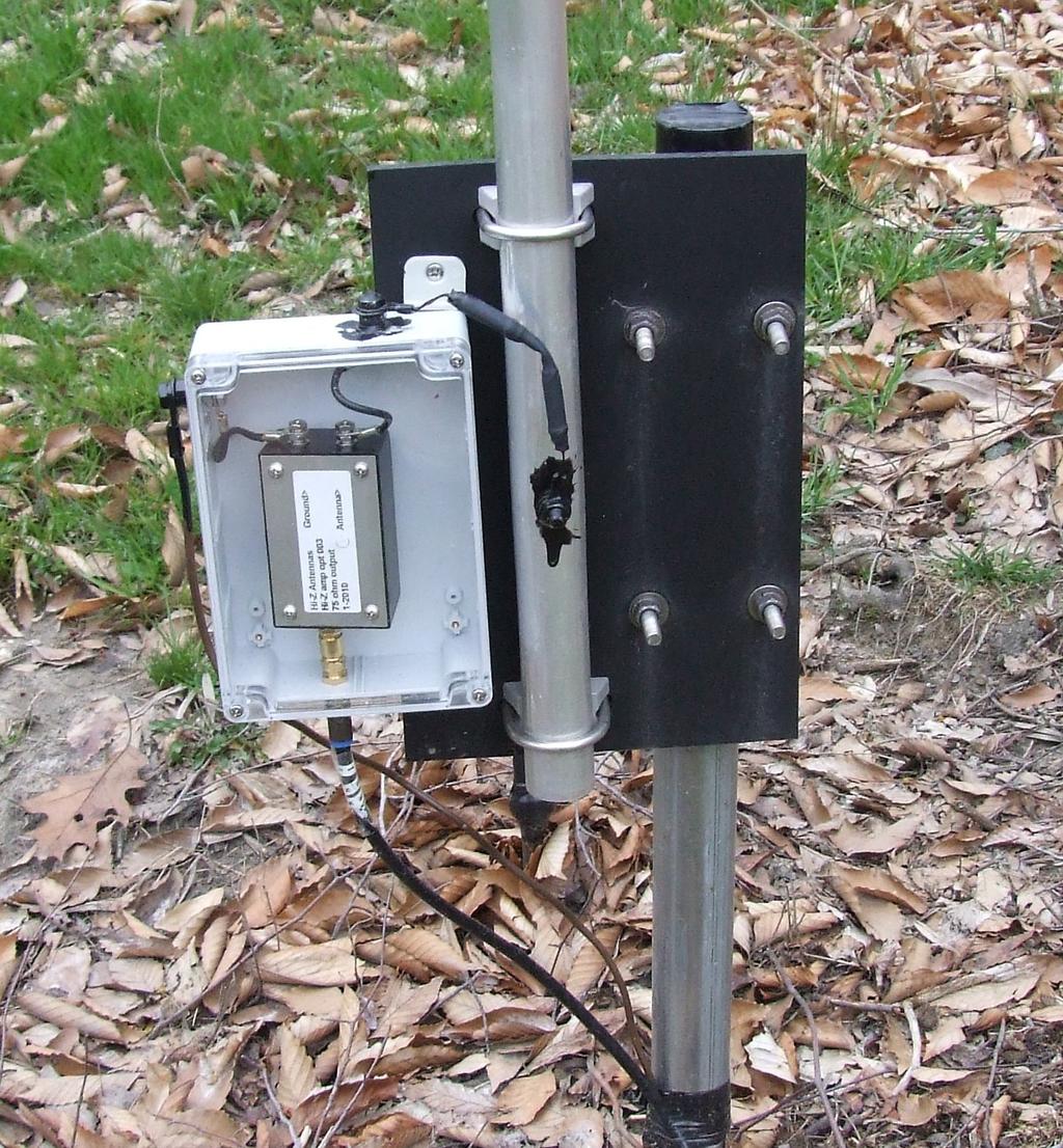
34 Vertical Dipole Establishing a true zero volt ground reference across the array area can be a challenge. Ground rods, mounting poles, or radial systems can be real work and time consuming to install. Once installed, they are somewhat permanent and yet more work to relocate, and hard to tweak. One alternative is to use a balanced vertical dipole that does not reference ground at all. Combined with a portable base, antenna experimentation, tweaking, and painless seasonal setup and removal becomes very easy. The only inconvenience is running the transmission line up though the bottom tube to aid in decoupling the line from the antenna. This is a common issue with vertical dipoles.
35 Vertical Dipole (2) V- What does the active buffer work against? V- 0V V+ V- Balanced, true differential V+ 0V Unbalanced, end fed, GND referenced Any signal/energy/noise on GND will enter buffer V+ Monopole Dipole


36 Vertical Dipole (3)


37 Vertical Dipole (4)
38 Low Pass Signal Filtering Active vertical antennas tend to have a wide bandwidth with a signal peak at the frequency of ½ wavelength resonance (previous slides). In the multiple transmitter contest environment, this can create a problem if energy from the higher bands (40m, 20m, etc.) enters the array and creates artifacts, such as overload, IM products, pumping, etc. Another good word is crud. You know it when you have it. The usual solution is some form of filtering. Since there are active devices right at the antenna base, we would like to install filtering before we get to their doorstep. One per antenna. Filters usually alter the magnitude and phase response of even the desired signal. The concern, as always, is antenna sameness, and that the filter does not introduce phasing errors while doing its job. The filter ports are also a bit unusual in this application, since there is a high impedance buffer on one side, and a highly reactive short vertical on the other.
39 Low Pass Signal Filtering (2) After detecting some contest crud, effort was put into looking at filter solutions that preserved the phasing of the array while knocking down the crud to the point where it was not a problem after hours and hours of contesting. Solutions were found, but I must admit, I can t fully explain how they work at this point! They involve using hand selected RF chokes. The filtering appears to rely upon a combination of the chokes, the antenna length, and the base capacitance. While the base capacitance and buffer input are relatively stable, the antenna impedance is a function of frequency, and the RF chokes are self resonant, which is hardly stable. The level of filtering is in the range of 10 to 20 db, which would normally be considered a poor filter. But, for removing the crud, they do the job. A test jig was set up using a noise source, antenna impedance simulator, filter, and spectrum analyzer (0.1 to 30 MHz) connected to the output of a high impedance buffer.

 No")
40 Low Pass Signal Filtering (3) No Filter Filter
41 Low Pass Signal Filtering (4) An interesting aspect of the filter is that it increases the antenna gain at the low frequencies. So, in addition to filtering at and above 40m, there are a few db of additional gain on 160 and 80m. But, as can be seen from the spectrum analyzer, it s necessary to control the filter response to make sure it s the same (from filter to filter) on 160 and 80 m. I will write up this information when I figure out exactly how the filter works, especially in the context of the whole antenna. Another idea is to select vertical lengths that are not ½ wavelength on a higher band (avoid resonance).
42 Feedline Chokes Where is my antenna? (72 /240 ) (108 /996 ) Transmission lines, control cables, any conductor, can act like an antenna and carry antenna currents. Another term is common mode currents. The currents can cause problems by reradiation to nearby antennas, and/or, direct connection to antennas, transmission lines, or grounds that are really not low impedance grounds. The problem is exacerbated when the lines are resonant. The two conditions to be aware of are lines ¼ wavelength long with a high impedance on one end and a low impedance on the other, and, a ½ wavelength line with a high impedance on both ends. Both of these situations encourage RF current flow. (one is a grounded ¼ wavelength and the other is a floating ½ wavelength dipole) When a line is acting like an antenna, and we wish that it weren t, we have two tools that can be used to discourage resonance chokes and grounds. A choke adds a high impedance point; a ground, assuming it s a quality ground, adds a low impedance point. When correctly applied, the problem can be reduced or eliminated. Turn resonance into anti-resonance. Often times a matter of degree, not absolutes.
43 Feedline Chokes (2) Chokes every ¼ wavelength down a line are very effective in breaking up resonance. The thinking process is similar to the old days of adding insulators to metal tower guy lines. But, if we have chokes every ¼ wavelength, at twice the frequency the chokes are ½ wavelength apart, and that s exactly resonant! This leads to the realization that it is possible for chokes or grounds to make a problem worse, or fix a problem on one band while making it worse on another. If you have a receiving array that is not performing up to expectations, experimenting with chokes on the various lines can pay big dividends. Consider both ends of a cable as well as breaking up lengths longer than ¼ wavelength on the frequency you are evaluating. Look at all cables, not just transmission lines. DC control cables can be choked with standard RF chokes. I tend to cut up a 1000 box of RG-6 into a set of useful lengths and then use as many as needed to span some distance, adding chokes between sections. Lines between the elements and the phasing box almost always need to be the same length, but not a specific length. This only applies to lines that are run flat (SWR = 1). That s usually the case in receiving arrays, but not transmitting.
44 Feedline Chokes (3) Example: 4 Square. Phasing selected to create side and rear nulls. Good for testing, since nulls fall in 3 of the 4 directions. By dumb luck, nearly aligned with local AM radio station. Chokes already installed at X. What is the difference with chokes installed at Y? Feedlines about 60 feet long. No grounding anywhere.

45 Feedline Chokes (4)
46 Feedline Chokes (5) Used S Meter Lite program to capture signal levels. In addition to improving side and rear nulls, the chokes at the phasing box caused the overall array output to drop by about 6 db. Less unwanted antenna! This is good news! Although the output level was down, the signal to noise ratio was improved, and array performance clearly went up on all bands.
47 Feedline Chokes (6) Design/construction follows ideas and concepts used on other transmission line/cable chokes. Little power is involved because these are used only for reception. If used on lines running to the elements, sameness matters and should be verified. Avoid impedance bumps and make internal lines the same length. Mix 73 BN with 75 Ohm twisted pair, Mix 43 BN with RG-178 (50 Ohms), Mix 43 BN with RG-179 (75 Ohms). Clamp on chokes can certainly be used, but I personally find them not as effective (5 to 6 turns needed), and cumbersome.

48 Feedline Chokes (7) Small Core 50 Big Core 75 Twisted Pair 75
49 Conclusions I think in terms of minimizing the phasing errors in an array, and what is the required tolerance to keep individual errors under 1%. While that may sound strict, there are so many places where you can introduce error that if you are not vigilant, you can easily drop way too much performance on the ground drop by drop by drop. Sameness is usually far more important that target values. High impedance buffers create floating sections of antenna with a current maximum in the middle, and voltage maximums on the ends. Voltage peaks occur at the ½ wavelength points. If you avoid frequencies where the antenna is naturally approaching resonance (1/4 to ½ wavelength), the length of the antenna directly determines the voltage output. V = L X Fs. Doubling the length of the antenna results in 6 db of additional gain. Reducing the length by ½ drops the gain by 6 db.
50 Conclusions (2) If you want to ignore mutual coupling, keep the vertical length under 1/8 wavelength at the highest frequency of operation, ~31 feet at 4.0 MHz. Antenna diameter is not an important parameter except near resonance. Antenna length/construction should always be carefully controlled and made the same. Base shunt capacitance lowers voltage output and can create magnitude errors even for antennas that otherwise appear to be the same. Strive for sameness, resorting to trimmer capacitors if necessary. Series inductance alters the antenna response, and is a great way to increase gain at the expense of bandwidth. But, controlling the gain and phase shifts to preserve sameness is hard. For unbalanced end fed ground referenced verticals, ground rods, mounting poles, and radials all make acceptable grounds. I ve used 8 radials each 10 long without problems. If your array is not exhibiting the expected performance, experiment with chokes on each end of every line, and in the middle of long lines. Check every band that is important to you.
Chapter 6 Antenna Basics. Dipoles, Ground-planes, and Wires Directional Antennas Feed Lines
 Chapter 6 Antenna Basics Dipoles, Ground-planes, and Wires Directional Antennas Feed Lines Some General Rules Bigger is better. (Most of the time) Higher is better. (Most of the time) Lower SWR is better.
4/29/2012. General Class Element 3 Course Presentation. Ant Antennas as. Subelement G9. 4 Exam Questions, 4 Groups
 General Class Element 3 Course Presentation ti ELEMENT 3 SUB ELEMENTS General Licensing Class Subelement G9 Antennas and Feedlines 4 Exam Questions, 4 Groups G1 Commission s Rules G2 Operating Procedures
General License Class Chapter 6 - Antennas. Bob KA9BHD Eric K9VIC
 General License Class Chapter 6 - Antennas Bob KA9BHD Eric K9VIC Learning Objectives Teach you enough to get all the antenna questions right during the VE Session Learn a few things from you about antennas
Low Band Receiving Antennas
 Low Band Receiving Antennas (on a city lot) Ned Stearns, AA7A How do you know you need a Receive Antenna? Scenario #1 Many DX stations hear you much better than you hear them Scenario #2 When your DXerneighbor
1) Transmission Line Transformer a. First appeared on the scene in 1944 in a paper by George Guanella as a transmission line transformer, the 1:1
 Transmission Line Transformer a. First appeared on the scene in 1944 in a paper by George Guanella as a transmission line transformer, the 1:1") 1) Transmission Line Transformer a. First appeared on the scene in 1944 in a paper by George Guanella as a transmission line transformer, the 1:1 Guanella Balun is the basic building Balun building block.
1) Transmission Line Transformer a. First appeared on the scene in 1944 in a paper by George Guanella as a transmission line transformer, the 1:1 Guanella Balun is the basic building Balun building block.
MFJ-249B HF/VHF SWR ANALYZER
 TABLE OF CONTENTS MFJ-249B... 2 Introduction... 2 Powering The MFJ-249B... 3 Battery Installation... 3 Alkaline Batteries... 3 NiCd Batteries... 4 Power Saving Mode... 4 Operation Of The MFJ-249B...5 SWR
VE7CNF - 630m Antenna Matching Measurements Using an Oscilloscope
 VE7CNF - 630m Antenna Matching Measurements Using an Oscilloscope Toby Haynes October, 2016 1 Contents VE7CNF - 630m Antenna Matching Measurements Using an Oscilloscope... 1 Introduction... 1 References...
Basic Wire Antennas. Part II: Loops and Verticals
 Basic Wire Antennas Part II: Loops and Verticals A loop antenna is composed of a single loop of wire, greater than a half wavelength long. The loop does not have to be any particular shape. RF power can
Least understood topics by most HAMs RF Safety Ground Antennas Matching & Feed Lines
 Least understood topics by most HAMs RF Safety Ground Antennas Matching & Feed Lines Remember this question from the General License Exam? G0A03 (D) How can you determine that your station complies with
A New Approach for Measuring Complex Antenna Currents in a Vertical Array
 A New Approach for Measuring Complex Antenna Currents in a Vertical Array Greg Ordy, W8WWV ordy@seed-solutions.com solutions.com 2008 Dayton Hamvention Antenna Forum Overview This presentation is organized
A Triangle for the Short Vertical
 1 von 11 03.03.2015 12:37 A Triangle for the Short Vertical Operator L. B. Cebik, W4RNL Last month, I described a triangle array of three full-size vertical dipoles for 40 meters (with 30 meters as a bonus).
Some Observations on the K9AY Receive Directional Antenna
 Some Observations on the K9AY Receive Directional Antenna Tom McDermott, N5EG January 12, 2010 The K9AY antenna is a popular, compact receive directional antenna commonly used on the 80 and 160 meter amateur
Page 1The VersaTee Vertical 60m, 80m Modular Antenna System Tutorial Manual
 Page 1The VersaTee Vertical 60m, 80m Modular Antenna System Tutorial Manual by: Lou Rummel, KE4UYP Page 1 In the world of low band antennas this antenna design is unique in many different ways. 1. It is
his report is my recent analysis of the EH antenna using the Pspice program and considering the antenna as a set of circuit elements.
 his report is my recent analysis of the EH antenna using the Pspice program and considering the antenna as a set of circuit elements. The antenna can be considered as a set of circuit elements because
WHY YOU NEED A CURRENT BALUN
 HF OPERATORS WHY YOU NEED A CURRENT BALUN by John White VA7JW NSARC HF Operators 1 What is a Balun? A BALUN is a device typically inserted at the feed point of a dipole-like antenna wire dipoles, Yagi
Beams and Directional Antennas
 Beams and Directional Antennas The Horizontal Dipole Our discussion in this chapter is about the more conventional horizontal dipole and the simplified theory behind dipole based designs. For clarity,
Jacques Audet VE2AZX. Nov VE2AZX 1
 Jacques Audet VE2AZX VE2AZX@amsat.org Nov. 2006 VE2AZX 1 - REASONS FOR USING A BALUN - TYPES OF BALUNS - CHECK YOUR BALUN WITH AN SWR ANALYZER - MEASURING THE IMPEDANCE OF A NUMBER OF FERRITES - IMPEDANCE
"Natural" Antennas. Mr. Robert Marcus, PE, NCE Dr. Bruce C. Gabrielson, NCE. Security Engineering Services, Inc. PO Box 550 Chesapeake Beach, MD 20732
 Published and presented: AFCEA TEMPEST Training Course, Burke, VA, 1992 Introduction "Natural" Antennas Mr. Robert Marcus, PE, NCE Dr. Bruce C. Gabrielson, NCE Security Engineering Services, Inc. PO Box
# -antenna (hash) 4 direction switchable array
 4 direction switchable array") # -antenna (hash) 4 direction switchable array Feasibility study Paper on CCF & OHDXF cruise 4.1.2012 Pekka Ketonen 4.2.2012 OH1TV 1 4 direction, instant switching 4.2.2012 OH1TV 2 Features Instant direction
# -antenna (hash) 4 direction switchable array Feasibility study Paper on CCF & OHDXF cruise 4.1.2012 Pekka Ketonen 4.2.2012 OH1TV 1 4 direction, instant switching 4.2.2012 OH1TV 2 Features Instant direction
Array Solutions Four Square Array Manual and User s Guide
 Array Solutions Four Square Array Manual and User s Guide Array Solutions Four Square Array Pattern Steering System Congratulations! You have selected one of the finest phased array steering systems made.
Development of a noval Switched Beam Antenna for Communications
 Master Thesis Presentation Development of a noval Switched Beam Antenna for Communications By Ashraf Abuelhaija Supervised by Prof. Dr.-Ing. Klaus Solbach Institute of Microwave and RF Technology Department
End Fed Half Wave Antenna Coupler
 End Fed Half Wave Antenna Coupler The finished End Fed Half Wave antenna coupler. Centre fed half wave dipoles make great, simple and effective antennas for the HF bands. Sometimes however, the centre
Antennas 101 Don t Be a 0.97 db Weakling! Ward Silver NØAX
 Antennas 101 Don t Be a 0.97 db Weakling! Ward Silver NØAX Overview Antennas 101 2 Overview Basic Antennas: Ground Plane / Dipole How Gain and Nulls are Formed How Phased Arrays Work How Yagis Work (simplified)
Easy to Build Low Band Receiving Antennas for Small and Large Lots
 Easy to Build Low Band Receiving Antennas for Small and Large Lots Small antennas High performance antennas Quantitative performance evaluation Frank Donovan W3LPL Why Receiving Antennas? Much better performance
Last year I described several Low Band RX antennas that would enable you to hear DX stations on 160, 80 and 40M. This will show you how to build
 Last year I described several Low Band RX antennas that would enable you to hear DX stations on 160, 80 and 40M. This will show you how to build transmit antennas that will help you break the pileups!
Chapter 5.0 Antennas Section 5.1 Theory & Principles
 Chapter 5.0 Antennas Section 5.1 Theory & Principles G3C11 (B) p.135 Which of the following antenna types will be most effective for skip communications on 40-meters during the day? A. A vertical antenna
The Fabulous Dipole. Ham Radio s Most Versatile Antenna
 The Fabulous Dipole Ham Radio s Most Versatile Antenna 1 What is a Dipole? Gets its name from its two halves One leg on each side of center Each leg is the same length It s a balanced antenna The voltages
L. B. Cebik, W4RNL. 1. You want to get on 160 meters for the first time (or perhaps, for the first time in a long time).
.") L. B. Cebik, W4RNL The following notes rest on a small set of assumptions. 1. You want to get on 160 meters for the first time (or perhaps, for the first time in a long time). 2. You want to set up the
L. B. Cebik, W4RNL The following notes rest on a small set of assumptions. 1. You want to get on 160 meters for the first time (or perhaps, for the first time in a long time). 2. You want to set up the
Other Arrays CHAPTER 12
 CHAPTER 12 Other Arrays Chapter 11 on phased arrays only covered arrays made of vertical (omnidirectional) radiators. You can, of course, design phased arrays using elements that, by themselves, already
Transforms and electrical signal into a propagating electromagnetic wave OR vise versa. - Transducer goes both ways. TX and RX antennas have
 Gary Rondeau AF7NX Transforms and electrical signal into a propagating electromagnetic wave OR vise versa. - Transducer goes both ways. TX and RX antennas have different jobs. For TX want to generate as
Range Considerations for RF Networks
 TI Technology Days 2010 Range Considerations for RF Networks Richard Wallace Abstract The antenna can be one of the most daunting components of wireless designs. Most information available relates to large
Antenna Fundamentals
 HTEL 104 Antenna Fundamentals The antenna is the essential link between free space and the transmitter or receiver. As such, it plays an essential part in determining the characteristics of the complete
ANTENNAS. I will mostly be talking about transmission. Keep in mind though, whatever is said about transmission is true of reception.
 Reading 37 Ron Bertrand VK2DQ http://www.radioelectronicschool.com ANTENNAS The purpose of an antenna is to receive and/or transmit electromagnetic radiation. When the antenna is not connected directly
The Amazing MFJ 269 Author Jack Tiley AD7FO
 The Amazing MFJ 269 Author Jack Tiley AD7FO ARRL Certified Emcomm and license class Instructor, Volunteer Examiner, EWA Technical Coordinator and President of the Inland Empire VHF Club What Can be Measured?
COAXIAL TRANSMISSION LINE COMMON-MODE CURRENT
 COAXIAL TRANSMISSION LINE COMMON-MODE CURRENT Introduction Coaxial transmission lines are popular for their wide frequency bandwidth and high resistance to electromagnetic interference (EMI). Coax cables
CHAPTER 8 ANTENNAS 1
 CHAPTER 8 ANTENNAS 1 2 Antennas A good antenna works A bad antenna is a waste of time & money Antenna systems can be very inexpensive and simple They can also be very expensive 3 Antenna Considerations
RX Directional Antennas. Detuning of TX Antennas.
 1. Models Impact of Resonant TX antennas on the Radiation Pattern of RX Directional Antennas. Detuning of TX Antennas. Chavdar Levkov, lz1aq@abv.bg, www.lz1aq.signacor.com 2-element small loops and 2-element
Newcomers And Elmers Net: Wire Antennas Robert AK3Q
 Newcomers And Elmers Net: Wire Antennas 02-07-16 Robert AK3Q Wire antennas represent one of the greatest values in the radio hobby world. For less than the cost of a good meal out on the town you can buy
EMG4066:Antennas and Propagation Exp 1:ANTENNAS MMU:FOE. To study the radiation pattern characteristics of various types of antennas.
 OBJECTIVES To study the radiation pattern characteristics of various types of antennas. APPARATUS Microwave Source Rotating Antenna Platform Measurement Interface Transmitting Horn Antenna Dipole and Yagi
MFJ-219/219N 440 MHz UHF SWR Analyzer TABLE OF CONTENTS
 MFJ-219/219N 440 MHz UHF SWR Analyzer TABLE OF CONTENTS Introduction...2 Powering The MFJ-219/219N...3 Battery Installation...3 Operation Of The MFJ-219/219N...4 SWR and the MFJ-219/219N...4 Measuring
ANTENNAS FEED POINTS. An antenna is a mechanical structure by which electromagnetic waves are sent out or received.
 ANTENNAS An antenna is a mechanical structure by which electromagnetic waves are sent out or received. An antenna accomplishes this by being made so that its structure will be resonant at the frequency
Improving Performance of Arrays
 Improving Performance of Arrays Richard C. Jaeger, K4IQJ Robert L. Schafer, KA4PKB Auburn, AL Dayton Hamvention, May 18, 2012 K4IQJ@mindspring.com INTRODUCTION Introduction & Background RDF Definition
L. B. Cebik, W4RNL. Basic Transmission Line Properties
 L. B. Cebik, W4RNL In the course of developing this collection of notes, I have had occasion to use and to refer to both series and parallel coaxial cable assemblies. Perhaps a few notes specifically devoted
Yagi beam antennas CHAPTER 10 COMPOSITION OF A BEAM ANTENNA _
 CHAPTER 10 Yagi beam antennas The Yagi beam antenna (more correctly, the Yagi Uda antenna, after both of the designers of Tohoku University in Japan 1926) is unidirectional. It can be vertically polarized
Device Interconnection
 Device Interconnection An important, if less than glamorous, aspect of audio signal handling is the connection of one device to another. Of course, a primary concern is the matching of signal levels and
Portable Vertical Antenna for 75m & 40m
 Portable Vertical Antenna for 75m & 40m BOXBORO August 2012 Jacques VE2AZX Web: ve2azx.net 1 Objectives 1- Portable Antenna for 75m et 40m 2- Low radiation angle for DX 3- Efficient 4- Easy to install.
UNIT Write short notes on travelling wave antenna? Ans: Travelling Wave Antenna
 UNIT 4 1. Write short notes on travelling wave antenna? Travelling Wave Antenna Travelling wave or non-resonant or aperiodic antennas are those antennas in which there is no reflected wave i.e., standing
The design of Ruthroff broadband voltage transformers M. Ehrenfried G8JNJ
 The design of Ruthroff broadband voltage transformers M. Ehrenfried G8JNJ Introduction I started investigating balun construction as a result of various observations I made whilst building HF antennas.
Feed Line Currents for Neophytes.
 Feed Line Currents for Neophytes. This paper discusses the sources of feed line currents and the methods used to control them. During the course of this paper two sources of feed line currents are discussed:
Trees, vegetation, buildings etc.
 EMC Measurements Test Site Locations Open Area (Field) Test Site Obstruction Free Trees, vegetation, buildings etc. Chamber or Screened Room Smaller Equipments Attenuate external fields (about 100dB) External
Install as much wire/tubing as possible Electrically short antennas Minimize matching losses Good ground for verticals Maximizes antenna efficiency
 Jim Wolf KR9U Install as much wire/tubing as possible Electrically short antennas Minimize matching losses Good ground for verticals Maximizes antenna efficiency Far-away ground conditions determine low
4 Antennas as an essential part of any radio station
 4 Antennas as an essential part of any radio station 4.1 Choosing an antenna Communicators quickly learn two antenna truths: Any antenna is better than no antenna. Time, effort and money invested in the
Optimizing Your Stations Performance
 Optimizing Your Stations Performance A few hints / techniques, recommendations for getting the most RF out to the Antenna from your HF, VHF / UHF station. Tonights Presenters: Doug Theriault NO1D John
Traveling Wave Antennas
 Traveling Wave Antennas Antennas with open-ended wires where the current must go to zero (dipoles, monopoles, etc.) can be characterized as standing wave antennas or resonant antennas. The current on these
Cray Valley Radio Society. Real Life Wire Antennas
 Cray Valley Radio Society Real Life Wire Antennas 1 The basic dipole The size of an antenna is determined by the wavelength of operation In free space: ~3x10 8 m/s Frequency x Wavelength = Speed of Light,
SOME USES FOR RF1,RF5 and VA1 ANALYSTS. SWR Measurement
 SOME USES FOR RF1,RF5 and VA1 ANALYSTS THE HANDIEST INSTRUMENTS IN DECADES! When you put up an antenna in the the old days, it could be a real struggle. The only way to tell if it was tuned to the right
Milton Keynes Amateur Radio Society (MKARS)
") Milton Keynes Amateur Radio Society (MKARS) Intermediate Licence Course Feeders Antennas Matching (Worksheets 31, 32 & 33) MKARS Intermediate Licence Course - Worksheet 31 32 33 Antennas Feeders Matching
Milton Keynes Amateur Radio Society (MKARS) Intermediate Licence Course Feeders Antennas Matching (Worksheets 31, 32 & 33) MKARS Intermediate Licence Course - Worksheet 31 32 33 Antennas Feeders Matching
Intermediate Course (5) Antennas and Feeders
 Antennas and Feeders") Intermediate Course (5) Antennas and Feeders 1 System Transmitter 50 Ohms Output Standing Wave Ratio Meter Antenna Matching Unit Feeder Antenna Receiver 2 Feeders Feeder types: Coaxial, Twin Conductors
Intermediate Course (5) Antennas and Feeders 1 System Transmitter 50 Ohms Output Standing Wave Ratio Meter Antenna Matching Unit Feeder Antenna Receiver 2 Feeders Feeder types: Coaxial, Twin Conductors
Tuning a 160M full sized vertical with strong AM broadcast RF present on the antenna. Jay Terleski, WX0B
 Tuning a 160M full sized vertical with strong AM broadcast RF present on the antenna. Jay Terleski, WX0B I often get asked about how to match a ¼ WL vertical to a 50 ohm transmission line and what to do
SWL Receiving Antenna Experiments
 SWL Receiving Antenna Experiments Introduction I have a lot to learn about SWL antennas. What follows are some brief experiments I performed in late October 2005. I have been experimenting with a half
A short, off-center fed dipole for 40 m and 20 m by Daniel Marks, KW4TI
 A short, off-center fed dipole for 40 m and 20 m by Daniel Marks, KW4TI Version 2017-Nov-7 Abstract: This antenna is a 20 to 25 foot long (6.0 m to 7.6 m) off-center fed dipole antenna for the 20 m and
CHAPTER - 6 PIN DIODE CONTROL CIRCUITS FOR WIRELESS COMMUNICATIONS SYSTEMS
 CHAPTER - 6 PIN DIODE CONTROL CIRCUITS FOR WIRELESS COMMUNICATIONS SYSTEMS 2 NOTES 3 INTRODUCTION PIN DIODE CONTROL CIRCUITS FOR WIRELESS COMMUNICATIONS SYSTEMS Chapter 6 discusses PIN Control Circuits
AA-35 ZOOM. RigExpert. User s manual. Antenna and cable analyzer
 AA-35 ZOOM Antenna and cable analyzer RigExpert User s manual . Table of contents Introduction Operating the AA-35 ZOOM First time use Main menu Multifunctional keys Connecting to your antenna SWR chart
Technician Licensing Class. Lesson 4. presented by the Arlington Radio Public Service Club Arlington County, Virginia
 Technician Licensing Class Lesson 4 presented by the Arlington Radio Public Service Club Arlington County, Virginia 1 Quiz Sub elements T6 & T7 2 Good Engineering Practice Sub element T8 3 A Basic Station
Experiment 1: Instrument Familiarization (8/28/06)
") Electrical Measurement Issues Experiment 1: Instrument Familiarization (8/28/06) Electrical measurements are only as meaningful as the quality of the measurement techniques and the instrumentation applied
Electrical Measurement Issues Experiment 1: Instrument Familiarization (8/28/06) Electrical measurements are only as meaningful as the quality of the measurement techniques and the instrumentation applied
MODERN AM BROADCAST STATIONS AM STEREO CQUAM WITH DDS
 MODERN AM BROADCAST STATIONS AM STEREO CQUAM WITH DDS DDS EXCITER OPERATING MANUAL 20W CARRIER - 80W PEP WHAT IS DDS? IT IS THE INITIALS OF THE WORDS DIRECT DIGITAL SYNTHESIZER. THAT MEANS: DIRECT DIGITAL
Antenna? What s That? Chet Thayer WA3I
 Antenna? What s That? Chet Thayer WA3I Space: The Final Frontier Empty Space (-Time) Four dimensional region that holds everything Is Permeable : It requires energy to set up a magnetic field within it.
A 2 ELEMENT 30 METER PARASITIC VERTICAL ARRAY PROJECT
 A 2 ELEMENT 30 METER PARASITIC VERTICAL ARRAY PROJECT Having killed off the 5B-DXCC purely using LOTW, it was time for the addition of a new band. 30 meters was selected based on lack of sunspots and a
A fool with a tool is still a fool. Measurements of an antenna loading coil by Frank F/N4SPP
 A fool with a tool is still a fool Measurements of an antenna loading coil by Frank F/N4SPP I have constructed a center-loaded mini-dipole, and used two of those to create a 2-element mini yagi beam antenna.
Antenna Fundamentals Basics antenna theory and concepts
 Antenna Fundamentals Basics antenna theory and concepts M. Haridim Brno University of Technology, Brno February 2017 1 Topics What is antenna Antenna types Antenna parameters: radiation pattern, directivity,
4.4. Experimental Results and Analysis
 4.4. Experimental Results and Analysis 4.4.1 Measurement of the IFA Against a Large Ground Plane The Inverted-F Antenna (IFA) discussed in Section 4.3.1 was modeled over an infinite ground plane using
Using EZNEC To Compare Antennas Part 2. Bill Leonard N0CU
 Using EZNEC To Compare Antennas Part 2 Bill Leonard N0CU Topics How polarization affects antenna performance How ground type affects antenna performance Example 1: 48 Shunt Fed Tower as 40M Vertical Initially,
The Basics of Patch Antennas, Updated
 The Basics of Patch Antennas, Updated By D. Orban and G.J.K. Moernaut, Orban Microwave Products www.orbanmicrowave.com Introduction This article introduces the basic concepts of patch antennas. We use
Transmission Line Signal Sampling By Don Steinbach, AE6PM
 Transmission Line Signal Sampling By Don Steinbach, AE6PM When I was finalizing the mechanical layout of my remotely-operated 3-position coaxial antenna switch (Fig. 1), I wanted to include a way to bring
A Relatively Simple160/80 No Tune/No Switch Dual CW Band Trap Antenna Using the Spiderbeam Mast
 A Relatively Simple160/80 No Tune/No Switch Dual CW Band Trap Antenna Using the Spiderbeam Mast This project originated with my request to the Contesting Top Band forum for thoughts on a transportable
The first thing to realize is that there are two types of baluns: Current Baluns and Voltage Baluns.
 Choosing the Correct Balun By Tom, W8JI General Info on Baluns Balun is an acronym for BALanced to UNbalanced, which describes certain circuit behavior in a transmission line, source or load. Most communications
Antennas Demystified Antennas in Emergency Communications. Scott Honaker N7SS
 Antennas Demystified Antennas in Emergency Communications Scott Honaker N7SS Importance of Antennas Antennas are more important than the radio A $5000 TV with rabbit ears will have a lousy picture Antennas
Connecting Your Rig To The Aether
 Connecting Your Rig To The Aether 1 Ward Harriman (AE6TY) Pacificon 18 1: of course, there is no Aether! Presentation Goals Review a common design to reinforce forgotten knowledge. Use that design to demonstrate
The Coaxial Trap Confusion (mostly resolved?)
") The Coaxial Trap Confusion (mostly resolved?) Background Antenna traps need an inductor and a capacitor in a parallel circuit to effectively cut off the end of the antenna for some higher frequency giving
The Coaxial Trap Confusion (mostly resolved?) Background Antenna traps need an inductor and a capacitor in a parallel circuit to effectively cut off the end of the antenna for some higher frequency giving
Antennas and Stuff. John Kernkamp WB4YJT
 Antennas and Stuff John Kernkamp WB4YJT John Kraus W8JK June 28, 1910 - July 18, 2004 Invented the helical antenna, the corner reflector, and the W8JK End-Fire array. In 1950 designed and built the Big
Technician License Course Chapter 4. Lesson Plan Module 9 Antenna Fundamentals, Feed Lines & SWR
 Technician License Course Chapter 4 Lesson Plan Module 9 Antenna Fundamentals, Feed Lines & SWR The Antenna System Antenna: Transforms current into radio waves (transmit) and vice versa (receive). Feed
Portable Magnetic Loop Antenna. KG5EAO Rick Bono
 Portable Magnetic Loop Antenna KG5EAO Rick Bono April 2, 2016 Overview Develop a Portable magnetic loop antenna for use on HF bands running QRP. Portable and easy to deploy Ideally run on the 40m through
One I had narrowed the options down, I installed some wire and started testing.
 Loft & Attic antennas for restricted spaces - M. Ehrenfried G8JNJ I ve recently been looking at designs for an efficient antenna that would fit in a loft. I hoped to find something that would work on with
Experiment 1: Instrument Familiarization
 Electrical Measurement Issues Experiment 1: Instrument Familiarization Electrical measurements are only as meaningful as the quality of the measurement techniques and the instrumentation applied to the
The below identified patent application is available for licensing. Requests for information should be addressed to:
 DEPARTMENT OF THE NAVY OFFICE OF COUNSEL NAVAL UNDERSEA WARFARE CENTER DIVISION 1176 HOWELL STREET NEWPORT Rl 02841-1708 IN REPLY REFER TO Attorney Docket No. 300104 25 May 2017 The below identified patent
Antenna Design for FM-02
 Antenna Design for FM-02 I recently received my FM-02 FM transmitter which I purchased from WLC. I researched the forum on what antennas where being used by the DIY community and found a nice write-up
ANTENNA DESIGN FOR FREE USING MMANA-GAL SOFTWARE
 ANTENNA DESIGN FOR FREE USING MMANA-GAL SOFTWARE 1. AVAILABLE ANTENNA DESIGN SOFTWARE EZNEC and 4nec2 are based upon the Numerical Electromagnetics Code, or NEC, which is a popular antenna modelling system
University of Pennsylvania Department of Electrical and Systems Engineering ESE319
 University of Pennsylvania Department of Electrical and Systems Engineering ESE39 Laboratory Experiment Parasitic Capacitance and Oscilloscope Loading This lab is designed to familiarize you with some
Technician License. Course
 Technician License Course Technician License Course Chapter 4 Lesson Plan Module - 9 Antenna Fundamentals Feed Lines & SWR The Antenna System The Antenna System Antenna: Transforms current into radio waves
6M HALO VERSON II + OPTIONAL 2M GROUND PLANE
 The halo is an omnidirectional, horizontally polarized antenna with about the same gain as a dipole but without the low elevation nulls off the ends (+5.5 to +3.5dBi variation for the Halo vs. +7.9 to
Active Antennas 4/28/2017
 1 Active Antenna??? What Why Theory Loops Verticals Dipoles Amplifier Considerations VE7KW experiments 2 What Simply an antenna with an amplifier - Automotive application - My first exposure to active
The shunt capacitor is the critical element
 Accurate Feedthrough Capacitor Measurements at High Frequencies Critical for Component Evaluation and High Current Design A shielded measurement chamber allows accurate assessment and modeling of low pass
SCHWARZBECK MESS - ELEKTRONIK An der Klinge 29 D Schönau Tel.: 06228/1001 Fax.: (49)6228/1003
6228/1003") Calibration of Vertical Monopole Antennas (9kHz - 30MHz) 11112gs VAMPINFO 1. Introduction Vertical Monopole Antennas are used for the measurement of the electric component of EM fields, especially in the
Calibration of Vertical Monopole Antennas (9kHz - 30MHz) 11112gs VAMPINFO 1. Introduction Vertical Monopole Antennas are used for the measurement of the electric component of EM fields, especially in the
Network Evaluation for the PW A10 Schematic Review Prepared by David Green; W7NE Revision: 1.0 Complete Friday, October 20, 2006
 Network Evaluation for the PW A Schematic Review Prepared by David Green; W7NE Revision:. Complete Friday, October 2, 26 Parametric analysis of the L network was conducted in an effort to understand the
Amateur Extra Manual Chapter 9.4 Transmission Lines
 9.4 TRANSMISSION LINES (page 9-31) WAVELENGTH IN A FEED LINE (page 9-31) VELOCITY OF PROPAGATION (page 9-32) Speed of Wave in a Transmission Line VF = Velocity Factor = Speed of Light in a Vacuum Question
Loop Antennas for HF Reception
 COMMUNICATIONS 74 CONFERENCE BRIGHTON Wednesday, June 5 1974 Session 5, Equipment Design Paper 5.3: Loop Antennas for HF Reception Contributed by: B.S.Collins, C & S Antennas Ltd., Knight Road, Rochester,
FCC Technician License Course
 FCC Technician License Course 2014-2018 FCC Element 2 Technician Class Question Pool Presented by: Tamiami Amateur Radio Club (TARC) WELCOME To the third of 4, 3-hour classes presented by TARC to prepare
Understanding Power Splitters
 Understanding Power Splitters How they work, what parameters are critical, and how to select the best value for your application. Basically, a 0 splitter is a passive device which accepts an input signal
Dr. John S. Seybold. November 9, IEEE Melbourne COM/SP AP/MTT Chapters
 Antennas Dr. John S. Seybold November 9, 004 IEEE Melbourne COM/SP AP/MTT Chapters Introduction The antenna is the air interface of a communication system An antenna is an electrical conductor or system
CHAPTER 5 PRINTED FLARED DIPOLE ANTENNA
 CHAPTER 5 PRINTED FLARED DIPOLE ANTENNA 5.1 INTRODUCTION This chapter deals with the design of L-band printed dipole antenna (operating frequency of 1060 MHz). A study is carried out to obtain 40 % impedance