EASE Sound System Design Project Report Evaluation
|
|
|
- Reginald Sharp
- 5 years ago
- Views:
Transcription
1 ECE Sound Reinforcement System Design Spring 2016 EASE Sound System Design Project Report Evaluation Group Members Time Spent* Initials Score** Mohammad Farooq MF Garrett McMindes GJM Zach Vander Missen ZVM *documented in Activity Log Sheet for each team member, included as Appendix A **may be different for each team member, based on amount of effort proportionally invested CRITERION SCORE WGT. PTS. Engineering design process System design constraint analysis Design constraint satisfaction Component selection Technical content / creativity Writing style / professionalism TOTAL Instructor comments:
2 ECE Sound Reinforcement System Design Spring 2016 TABLE OF CONTENTS Abstract ii 1.0 Engineering Design Process Design Constraint Analysis Design Constraint Satisfaction Equipment Selection Power Amplifier Requirements and Selection Signal Processing Requirements and Selection Mixing Console Requirements and Selection Microphone Requirements and Selection Rack Requirements and Design Cabling and Wiring Requirements Summary and Recommendations References 24 Appendix A: Activity Logs 26 Appendix B: Venue Illustrations 30 Appendix C: Loudspeaker Placement and EASE Simulation Results 32 Appendix D: Signal Path Wiring Diagram 37 Appendix E: Rack Design and Power Sequencing/Distribution 39 Appendix F: System Component List and Street Price Cost Estimate 41 Appendix G: Manufacturer Data Sheets 43 -i-
3 ECE Sound Reinforcement System Design Spring 2016 Abstract This report documents the design of a complete sound reinforcement system tailored for a generic, 6000-seat fan-shaped multi-purpose auditorium, with (approximately) 3750 seats on the main floor, 1500 seats on the first balcony, and 750 seats on the second balcony. Room dimensions and configuration should be chosen based on the specified seating capacity. The primary system design constraints are as follows: minimum SPL of 105 db at back row of (main floor) seating no more than 5 db variation in SPL over the entire seating space for the 500 Hz, 1 KHz, 2 KHz, 4 KHz, and 8 KHz frequency bands frequency response of 40 16,000 Hz 5 db %ALCONS no greater than 10% over entire seating space minimum 48-channel mixing console minimum of 4 separate monitor mixes (and corresponding monitor loudspeaker systems may choose an in-ear monitoring system as an alternative) support for a minimum of 20 compatible wireless microphone channels (include multiple transmitters/receivers to support all 20 channels) good assortment of general-purpose wired and wireless microphone systems for speaking, individual vocalists, a variety of musical instruments, choral performances digital media recording/playback capability all equipment mounted in rack cabinet(s) budget of $500,000 -ii-
4 ECE Sound Reinforcement System Design Spring Engineering Design Process The final venue designed for the sound reinforcement design bore the hallmarks of a typical fan-shaped auditorium. It in broad strokes has a narrow front of the seating area which was only a few feet wider than the stage space. This narrow dimension grew linearly toward the back of the main floor of the auditorium space. The width of the room doubles from the front to the back of the main floor seating area. The stage space itself typifies a proscenium stage. There is a straight front apron of the stage which protrudes in front of the curtain line. The ample back stage area continues to the back wall, and the entire back-stage area is approximated as a rectangular prism. In the house space, there are two additional balconies which augment the seating capacity of the main floor. The balconies are spaced vertically with sufficient ceiling clearance one on top of the other. The first balcony has a larger back-to-front distance than the second. Both balconies span the entire width of the auditorium space which they are above. All of the seating areas, on the main floor, first balcony, and the second balcony are divided into two halves by a center aisle. There are also supplementary side aisles as well as a front aisle on the main floor. All of these seating areas also incorporate a rake, meaning that the floor is sloped such that the back rows are higher up than the front rows. This facilitates improved viewing angle for the spectators as well as slightly mitigating the front to back footprint of the theater at the expense of the height. The main floor is raked gradually, at and angle compatible with standards set forth by the Americans with Disabilities Act. The first balcony matches the rake angle of the main floor. The second balcony is raked at a steeper angle, as was necessitated by the viewing angles offered to the viewers in the second balcony. The increased elevation of the second balcony level necessitated that the rake angel be steeper to afford the viewers in the back row and acceptable view. -1-
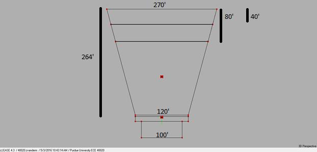
5 ECE Sound Reinforcement System Design Spring 2016 The specific dimensions of the final theater space are discussed in the following. The stage itself has a proscenium width of one hundred feet, and a proscenium height of thirtyfive feet. The stage space continues twenty-eight feet behind the curtain line. The backstage area has a ceiling height of eighty feet to accommodate a fly loft for the rigging system. The apron of the stage protrudes twelve feet in front of the curtain line. The apron width stretches out an additional fifteen feet on each side beyond the proscenium width for a total apron width of one hundred thirty feet. This distance, one hundred thirty feet, is the same as the width of the main floor at its front. The width of the main floor expands to two hundred and seventy feet in the back of the house. The run from the front of the house to the back is two hundred sixty-four feet. On the main floor the front aisle is four feet wide, the center aisle is six feet wide, and the side aisles are both seven feet wide. The shape of the balconies was computed to fit the required number of seats. The first balcony is eighty feet from front to back, and the second balcony is forty feet from front to back. Both balconies are spaced such that there is a ten foot ceiling height in the back row. Both balconies are flush to the back wall of the venue. The rake angle of the main floor is five degrees or approximately and inch rise for every foot of run. This is in compliance with the maximum ramp grade requirements set fort in the Americans with Disabilities Act. The first balcony mirrors the rake angle of the main floor at five degrees. The second balcony as is discussed above needed a steeper rake angle so it is raked at an eight degree incline. The full height of the ceiling over the main floor is seventy-three feet and six inches. The stage itself is raised three feet and six inches above the level of the front the main floor. The volume of the venue is four million two hundred fourteen thousand cubic feet. The various faces of the room were modeled as covered in reasonable surfaces which would be found in a similar auditorium. The materials considered were wood paneling, wood flooring covered in linoleum, plaster, cinder block, and carpeting. The carpeting was used to cover all floors in the auditorium, including the main floor, first balcony and second balcony. -2-
6 ECE Sound Reinforcement System Design Spring 2016 The wood flooring covered in durable linoleum was used to cover the stage itself both upstage and on the apron. Wood paneling covered the side walls of the venue. Cinder block was used to model all surfaces in the back stage area. Plaster covered all remaining surfaces including the ceiling, the balcony faces, the font wall, and the rear wall. The design process which created the final space was an iterative one. There were two complete candidate venues which were designed before the final auditorium which were found not to be suitable for the needs of the project. The main issues which the design needed to address were seat capacity, and compliance to the generic shape of a standard fan-shaped auditorium. The first two designs were not able to comply with the generic fan shape, of reasonable size constraints. The first prototype had a stage the size of a football field, and a ninety foot gap between the front row and the edge of the stage. The second prototype suffered from similar size infeasibility, and lack of compliance to reasonable auditorium dimensions, so the third and final model was necessitated. The group members who participated in the auditorium design portion of the project were Mohammad and Zach. Mohammad designed the first two prototypes. When the second prototype was found to be unworkable, like the first, the responsibility of venue design was transitioned to Zach who completed a fresh design which became the final auditorium space. The core difficulty in the initial designs lay in the misunderstanding of the mirrored drafting system in EASE. When a one hundred sixty foo stage was desired, the coordinates for its ends were set at one hundred sixty feet, but due to mirrored construction, this resulted in a three hundred twenty foot stage. Compounding this lack of understanding, many poor estimates of reasonable room dimensions, such as twenty foot wide aisles, five foot high stages and a over one hundred thousand square foot main floor caused the failures of the preliminary designs. -3-
7 ECE Sound Reinforcement System Design Spring Design Constraint Analysis In order to full use the design constraints in the previous section, the team had to examine the requirements of the theater closely. The first main design constraint was a sound pressure level of one hundred and five decibels. This required the team to use two powerful arrays capable of providing this level of decibels to the back row. Also the entire theater could not vary by more than five decibels. This constraint required the creation of a second array. The second array allowed the team to design a layout with a much more even coverage. This also helped increase the reliability of the system. In the event that one array becomes inoperable for a variety of reasons, the second array will still be able to provide some sound to those areas. While it will no longer meet the sound pressure level needs of the area, it is still preferable to having no sound at all. This set up also helps meet the budgetary constraints. The team was allotted five hundred thousand dollars to spend on the project as a whole, with the biggest expense easily being the speakers. The team originally looked into a layout that provided more even coverage by having a large number of line arrays scattered throughout the venue. However this method proved to be too expensive. In addition to requiring a large number of speakers, this method also required more supporting infrastructure to support those speakers. The speakers would need additional cabling and digital signals processing support modules. These would substantially increase the cost and maintenance of the system. The team next examined the other side of the spectrum, the use of a single large array that would provide sound to the entire theater with a variety of splay angles and offsets. This method provided the advantage of decreasing the number of speakers required, which also further reduced the number of digital signals processing modules needed as well as the length of cabling needed. However this method comes with two major drawbacks. The speaker array sacrifices -4-
8 ECE Sound Reinforcement System Design Spring 2016 good coverage and has substantial problems with combing. This compromises the sound quality received within the theater and is unacceptable for the sound system design. Additionally, this also poses safety concerns regarding the mounting of the speaker arrays. Since this would place a large number of speakers in close proximity, any mechanical failure on the part of one array has the potential to cause the entire set to have a mechanical failure. This could result in damages to the theater property or occupants. This increased exposure to mechanical failure is very concerning. Additionally, should the arrays experience trouble and be unable to emit sound, there is no backup system to make up for the sound. Because of these problems, the team selected another design to meet all required specifications. To meet the needed requirements, the team proposed a system using two hanging speaker arrays. The first array of ten speakers would be mounted around forty feet above the stage, in the middle of said stage. This array is pointed downwards at the floor at a slight angle, enabling it to cover most of the ground floor in the required sound pressure level. However it cannot reach the balconies and the back seats of the ground floor. To meet these requirements, the team implemented a second speaker array around one hundred feet in front of the first array, hanging from the ceiling. This array was able to cover both the first and second balcony, as well as the back seats of the ground floor. By combining these two arrays, the team was able to cover the entire theater is the needed sound pressure level. By carefully manipulating the offset and angle of the speakers in the arrays, the team was also able to provide a very consistent sound pressure level across the entire theater. This set up reduces the need for cabling and digital signals processing support to an acceptable level. It also does not co-locate the speakers. In the event of a mechanical failure, only half of the speakers are exposed to the issue, increasing the safety of the system. Additionally, in the event of the speakers being incapable of functioning, the second -5-
9 ECE Sound Reinforcement System Design Spring 2016 array adds a redundancy. If either speaker fails the other can partially make up for it. While this will not meet the requirements in total, it is still better than nothing. This placement of the loud speaker clusters would also suit the aesthetic needs of the theater. Both arrays would be fairly discrete and if need be they could be hidden. They are also placed in a position that would be easy to discretely wire the connections, being close enough to the mixing consoles and microphones to limit the delays experience by the system. Since the arrays are both hanging, safety was one of the driving forces behind the design. To meet this need, the team purchased the rigging kits from JBL. These kits are specially designed to handle hanging arrays, and if installed properly should significantly reduce any risk from the arrays. The other safety concern presented by any sound reinforcement system is electrical safety. Many of the modules needed for the system draw a significant amount of power, and this makes the safety precautions of the system of vital importance. The team solved this issue by purchasing several sequential power supplies. This is important because a sound system cannot be powered up all at the same time. Doing this would overdraw on the power and potentially damage equipment and cause a fire. The sequential power allows for the powering up of one system after another. Once a system has powered up and reached a steady state, the next system is free to begin its power up cycle. This reduces the power spike required as each machine is turned on. The final concern accounted for is the accommodation for the hearing impaired. As designers, the team wanted every person to be able to experience the majesty of the theater. Since the hearing impaired would not be able to benefit enough from the speaker array, the team needed an alternate solution. The first solution examined was using telecoil throughout the -6-
10 ECE Sound Reinforcement System Design Spring 2016 theater. While this would be convenient for the hearing impair, it was ultimately deemed too expensive for this application. The team ultimately decided on getting headsets that would directly pipe sound to the ears to the hearing impaired. -7-
11 ECE Sound Reinforcement System Design Spring Design Constraint Satisfaction In the designing of the loud speaker system, the team s first concern was the safety of the theaters patrons and its staff. Safety is of utmost importance, and the team discarded any ideas that put the safety and well-being of the occupants at risk. These speaker systems must also have a decent degree of tolerance. It is unlikely that the final implementation will exactly match the original design so it is important that no part of the specifications is barely met. The team designed for the specifications set by the customer to be exceeded by an amount large enough to account for any such problems and increase reliability. Finally, the team wanted to create a system that would not take substantial resources to maintain. This put an emphasis on limiting the number and placement of the speaker systems. To meet these goals the team examined several choices of systems. The first method explored was to use less powerful mains and rely on fills to offer a very even distribution of the SPL. To accomplish this, we would have had several different line arrays. The first would have been directly in front of the stage. This would have covered the first seats directly, as they were difficult to cover for any of the other speakers, especially near the edges of the stage. Speakers would also be mounted along the top of the stage to cover the ground floor. An additional line array would be place underneath the first balcony. These three arrays would have covered the entire ground floor of the theater. To cover the balconies, a pair of line arrays would be placed directly above the edge of the balconies, with the speakers for the first balcony being placed on the underside of the second balcony, and the speakers for the second balcony would be placed on the ceiling. This design would be good at covering the seats with a blanket of very even coverage, and would meet the specifications required. This method was not chosen because of the cost and maintenance constraints that the system would impose. The plan would call for a fairly substantial number of speakers, that -8-
12 ECE Sound Reinforcement System Design Spring 2016 would not be cheap, as well as any infrastructure such as digital signal processing devices and cabling that would be required to operate the speakers. The scattering of speakers throughout the entire theater would require the running of cables across the entire theater. It is also worth noting that many of these cables cannot go directly to their end destination. The cables must be hidden, or at a minimum discrete. Also, having substantially long lines with very delicate signals introduces the problem of a transmission line. By having these long connections, the task of wiring becomes substantially more complicated. The combination of the wiring and the sheer number of speakers also drives up the cost of this option, as each speaker needs to be wire, powered, and have digital signal progressing support. Overall, this layout was deemed impractical for the situation. The next option presented was to co-locate all of the speakers in a central cluster that would provide sound to the entire theatre. This method proposed a speaker mounting around one hundred feet from the front of the stage. Several arrays would face in the various direct, pointing downward at the floor at various angles. While these speakers would sacrifice the good coverage of the previous model, it would require fewer speakers and cabling. The lower number of speakers and the decreased amount of wiring would both reduce cost and maintenance required. Since the speakers are all located very close together, they all experience a very similar delay as well as a similar effect due to the transition line. This method also allows the user to place the signal source in such a location as to minimize the distance between the speaker and the source. This allows the user to eliminate the transmission line problem that the previous method struggled with. This design ran into several problems. The primary issue was the difficulty in creating an even sound pressure level across the entire theatre throughout the applicable frequency domains. As the frequency of the input signal increases, the output of the signal becomes narrower and beam shaped. This results in serious consistency issues regarding the -9-
13 ECE Sound Reinforcement System Design Spring 2016 output. This situation also raised safety concerns, as locating that much heavy and expensive equipment in one place can cause severe economic or personal damage should an accident occur. In this configuration, one array going down has the potential to bring down several arrays with it, resulting in catastrophic results. The team ultimately decided on an approach in between the previous two ideas. The plan consisted of two arrays of ten speakers each. The first array would be located around forty feet above the front of the stage. It would be mounted with specialized rigging purchased from the speaker manufacturer. This array would be responsible for covering much of the ground floor. Next, a second array was placed at the ceiling around a hundred feet in front of the previous array. This array would be pointed more sharply down, responsible for covering the two balconies and reinforcing the first array in the back rows of the ground floor. This approach had several advantages. First it allowed the group to use more powerful speakers in fewer places. By limiting the sound system to two arrays, the team limited the amount of wiring and digital signal processing required by the arrays. The arrays are also not located near enough to damage the other if a failure should occur. Finally, this method enables the speakers to provide the even sound pressure level required by the specifications. The team proposes to invest three hundred thousand dollars into top of the line JBL speakers. Since these speakers also have built in amplifiers, the amount of equipment required to support the speakers would be reduced. Combined with JBL s mounting equipment, the team believes that the JBL speakers would be safe to mount on the ceiling without any substantial risk to the occupants of the theatre. -10-
14 ECE Sound Reinforcement System Design Spring Equipment Selection 4.1 Power Amplifier Requirements and Selection The team determined that the best choice of speaker was the JBL VerTec 4889-DA. One of the aspects of the speaker that our group found most favorable is the built in power amplifier of the speakers. By building in the power amplifier, a separate module was not needed, reducing the team s need for additional equipment and making the total design similar and easier to maintain. These speakers are designed to produce an average of three thousand watts, with the peak power draw not exceeding six thousand watts. As long as the power requirement does not exceed these values, the speaker will be able to be successful in providing the sound pressure level requirements to all parts of the event space. In order to determine the amount of power required from the amplifier, the team first had to determine the required sound pressure level at the speakers themselves. Before venturing into the math, it is important to know that several simplifications have been made, and while they most likely have minimal effects on the results, it is still necessary to acknowledge these complications. The first simplification is the setting. The most basic calculation of sound pressure levels at a distance from the speaker relies on a transmission through the air. Unfortunately the theatre does not quite fit this model, leading to some error. Sound signals can be damped even more than expected by objects blocking sound from propagating. This could reduce the perceived sound pressure level seen at a certain distance. Additionally, sound could be bounced and the perceived sound at the final location could be different than expected. This is called multi-pathing, and it causes additional issues due to the delay introduced by the longer path that the signal took. In this case, the signal was considered to have propagated through the air with no reflections or attenuations due to the surroundings, outside of idealized air. Secondly, the sound pressure level at any point is the summation of the -11-
15 ECE Sound Reinforcement System Design Spring 2016 two speaker arrays. Not only will these arrays combine with differing signal strength, the two signals will likely be out of phase due to differing path lengths. These two effects are almost impossible to perfectly account for by hand, leading to the second assumption. The following math assumes that at every point, one speaker dominates the other such that one speaker is always negligible. While this setup mimics the goal of the two speaker arrays, at the transition point, it is less accurate. The sound pressure level is halved every six feet from the source. This leads to the following equation *log(30)= SPL at source. The one hundred and five is the required sound pressure level at the back rows. This math estimates that the back rows are approximately ninety feet from the speakers, which is approximately thirty meters. Doing this math leads to a one hundred and thirty five decibel sound pressure level required at the source. This is well below the maximum decibel capable of being produced by the speakers, which is one hundred and forty three decibels. This number is then used to find the power required by each speaker. This is based on the sensitivity of the speakers at different frequencies. The JBL VerTec 4889-DA has a ninety nine decibel low frequency sensitivity, a one hundred and two decibel mid frequency sensitivity, and a one hundred and sixteen decibel high frequency sensitivity. As is clearly evident, as the frequency increases, so does the sensitivity. The sensitivity is the decibels measured at one meter when one watt is introduced to the speaker. This leads to the equation of 10^(36/10)= power required. This equation is derived from the needed increase in sound pressure level of the system. To meet the requirement at low frequency, the sound pressure level will need to be increased by thirty six decibels. This leads to an answer of 3981 watts as the maximum power consumed. This is less than the peak power recommended by the speaker power amplifier. This is also the worst case for the speaker. -12-
16 ECE Sound Reinforcement System Design Spring Signal Processing Requirements and Selection The signals processing module is one of the most important parts of the system. A poor system will destroy the audio quality of the system as a whole. A good system will optimized the performance of the speakers with vital tweaks to maximize performance. One of the most important specifications of the signal processing requirements is a large sampling frequency. Due to sampling theory, the speed at which one samples limits the frequency range in which the output is consistent with the input. According to the Nyquist theorem, in order to avoid aliasing, a signal must be sampled at least twice as fast as the highest frequency in the signal. This frequency has the potential to set the cap for the maximum frequency of the input signal that can be used. The signals processing model also has the capability to improve the signal by applying a variety of filters, as well as boosting the various frequency ranges, which is especially important as many listeners prefer an increase in the low frequency components. The team ultimately decided on the Yamaha PM5D mixer. One of the reasons the team selected this mixer was the built in signals processing modules, allowing the mixer to fill the role typically occupied by another complete system. This simplifies the design of the system while making the system as a whole cheaper and easier to maintain. The Yamaha PM5D samples at ninety six kilohertz with twenty four bit analog to digital converters and similar digital to analog converters. The ninety six kilohertz sampling frequency enables high frequency components that extend well outside the human hearing range, enabling good sound fidelity. With that sampling frequency the mixer will be able to allow frequencies of forty six kilohertz, while most humans would be pressed to hear seventeen kilohertz. The analog to digital converters and digital to analog converters are both twenty four bits. While most music is encoded into sixteen bits, twenty four bits is considered the high definition version of sound. While the data takes up more space and takes longer to process, it provides two hundred and fifty six times as many -13-
17 ECE Sound Reinforcement System Design Spring 2016 quantization levels for the sound to take. This reduces what is known as the quantization error. When a sample is taken, the analog value is placed in one of many regions equally distributed along the range of the signal. The point is then recorded as the center amplitude of the region, introducing a rounding error. By increasing the number of bits, the number of regions increases exponentially, in this case introducing two hundred and fifty six regions where one had existed before. This reduces the rounding error by effectively making each region smaller. The signal processing capabilities also include several graphic equalizers. When a signal passes through any channel, it is modified, potentially causing significant error and distortion. By using the equalizers found on the Yamaha PM5D, this can be mitigated. The equalizers determine the noise caused by the channel and convolve the signal by the inverse of the channel. This causes the noise from the channel to cancel out the change, leaving the noise free final signal to reach its destination. In addition to the equalizer, the Yamaha PM5D also has several compressors. As with all computing, doing calculations and sending data takes time. Therefore it is vital for the system to minimize the time needed for each action. The compressor allows the system to send and store data more efficiently. By using one of many algorithms, the system is able to make the data effectively smaller. This allows the data to be more easily stored, and more quickly transmitted. Certain types of compression also allow for error checking upon reception. This error recognition can improve the total signal quality. Based on the wide variety of useful features and the simplicity of combining the mixer and the signal processing module, the team determined that the Yamaha PM5D was the clear choice as the system. -14-
18 ECE Sound Reinforcement System Design Spring Mixing Console Requirements and Selection The Mixing console requirements for this project were straightforward. They specified needs such as the number of mixing channels available and the number of auxiliary sends for monitor mixes. These specifications are important, because the number of channels available on the mixing console determines the freedom which the venues sound designer has to work with, and the number of monitor mixes determines how well performers needs can be accommodated. The number of channels on a board is the most critical specification on a mixing console. If the board has too few channels, segments of the program may have to go without mixing because there are too many microphone needs, and not enough channels to map them all to. In this scenario, for example minor roles in a play may forgo body microphones, which will worsen the overall performance quality based solely on the inadequate system. In a similar the number of monitor mixes available can drastically limit the ability to accommodate a musical performance. Each instrumentalist often wants their on monitor mix, and they have a difficult time playing up to their ability if they have a poorly mixed monitor. The case of too few monitor mixes would require performers to all share a single mix, which may not allow them to hear the other parts of the performance or themselves adequately. This also can contribute to maximum gain loss due to the limiting of the ability to isolate microphone from monitor near them in order to suppress possible feedback. It is well appointed that these two specifications are the main goal for the mixing console selection. The requirements for the project specify that the console must have at least forty-eight mixing channels. The requirements for the project also specify that the mixing console must have at least four separate monitor mixes. In addition to the specified requirement, there are other important board specifications that must be taken into consideration it the selection of a mixing console. Some of the considerations include: the number of physical mixing channels on -15-
19 ECE Sound Reinforcement System Design Spring 2016 the console, the amount of channel equalization available to each channel, and other additional channel based features such as a compressor, limiter or gate for the channel signal chain. In reviewing options for mixing consoles, a number of manufacturers were considered. These included Yamaha, Soundcraft, Behringer, Mackie, Sure, and Allen & Heath. From the many manufacturers considered, the final candidates were Soundcraft, and Yamaha. Soundcraft was considered for its reasonable price point in comparison to the competition. Yamaha was selected for the high quality and variety of the consoles it offered. After looking at a preliminary budget allotment, it was determined that there was an excess, and that it was prudent to consider the higher quality options from Yamaha. The board which was eventually chosen was the Yamaha PM5D. This board was chosen specifically for the conformity to the project requirements, its suitability to live sound mixing use (as opposes to mastering or recording) and the digital nature of the board which makes it compatible with the loudspeakers chose to use in the main clusters. The Yamaha PM5D sports forty-eight mixing channels and eight monitor mixes. It additionally supports a high resolution graphic equalized for every channel which helps in frontend signal processing. This high quality board meets or exceeds all needs of it. -16-
20 ECE Sound Reinforcement System Design Spring Microphone Requirements and Selection To meet the needed support for twenty wireless microphones the team examined many options. The first microphone system inspected was the QLXD24 Handheld Wireless Microphone system by Shure. This microphone system utilized twenty four bit audio with a one hundred and twenty decibel range. It also has an automatic channels scan to quickly find a good connection that is protected by the AES-256 encryption build in. Powered by a lithium-ion battery, the system would be incredibly useful for long usage. The system cost around one thousand dollars for each system, meaning the total cost for the microphone systems would be around twenty thousand dollars for the minimum set required for the theatre. The team deemed this microphone too expensive and outside the needs of the project. While twenty four bit audio is impressive, outside of the most attuned ear, it is next to impossible to differentiate twenty four bit audio from sixteen bit audio. Additionally, the biggest problem for audio quality for most performances is the actors themselves, reducing the incoming quality to the point where twenty four bit audio is not necessary. Also the encryption is not needed as it is unlikely anyone would attempt to sabotage the microphone system. Finally the cost is simply too high to justify the system. There are cheaper alternatives on the market that can also meet the necessary requirements. The team ultimately decided on the Audio-Technica 300 series wireless ATW This system featured two hundred selectable frequencies. It also has a True Diversity operation that helps reduce dropouts by selecting the better signal of two independent receiver sections. The system also has digital ToneLock squelch, and has a red light to notify the user of low battery power, loss of signal, or input overload. Also the receivers are sized to be able to be mounted side by side on a single 19 rack space. This will allow for a more condensed rack system. The -17-
21 ECE Sound Reinforcement System Design Spring 2016 system is designed to last eight hours and costs six hundred and fifty dollars per system, making the total cost a minimum of thirteen thousand dollars. However there are some draw backs to the system. Since the system uses an analog signal to transmit the audio, the signal is more susceptible to noise than the Shure system described above. Additionally the low range of the microphone is seventy hertz making the microphone ineffective at lower frequencies. The sytem does contain a mute system and also is powered by AA batteries making the replacement of power very easy and convenient. While the Shure system was the higher quality system, many of the advantages are minute and not relevant to the current project. The cost discrepancy is simply too great to justify the Shure system over the Audio Techina. Additionally the team will be buying Audio Technica ATW3193B systems. These are the head worn and clip on mic version of the above system. The final purchase distribution will be 16 headsets and four hand held mics. This distribution was picked to best suit the various needs of the theatre. A lead vocal or backup vocal requires a single handheld microphone per singer, and it is unlikely more than four vocals will be active at a time. Additionally coral groups only require one microphone for every fifteen to twenty people. This makes four hand held microphones mounted on stands more than sufficient. Additionally the four hand held mics can cover most configurations of instruments. The sixteen headset microphones could be clipped onto specific instruments for more mobile instruments such as an acoustic guitar that requires a microphone a short distance from the sound hole. The remaining sixteen headset microphones are ideal for a theatrical performance. It would allow for most performances to not struggle to have all of the necessary actors with microphones at the appropriate time. This setup is sufficient for a band with a vocalist and three instruments, as well as a play with a fair number of actors. If the theater wishes to have a full orchestra with a microphone on each instrument, the number of handheld microphones with stands will need to be increased. -18-
22 ECE Sound Reinforcement System Design Spring 2016 In addition to the wireless microphones, the team selected a number of wire microphones to augment the sound input. To facilitate the recording of symphonies and coral groups, the team added several hanging microphones. The team acquired four, enabling the accommodation of between sixty and eighty choir members. Additionally the team found microphones especially suited for a drum set. While the base microphone set was fine for most instruments, the drums required more specialized mics. The team selected microphones for the snap, kick, hi hat, and ton requirements. Finally the team got PCC microphones for the front of the stage, and shotgun microphones for the back. -19-
23 ECE Sound Reinforcement System Design Spring Rack Requirements and Design The selection of racking Equipment for the auditorium space was straightforward and lent itself to a clear-cut correct design. The main considerations were what equipment needed to be stored where and how it need to be powered. Considering the problem from this lens highlights two areas of need. The first area of need is all of the equipment that is integral to the operation of the live sound mixing position. This includes playback equipment, the receivers for all wireless micing systems as well as any peripheral support for the receivers. These things along with a solution for powering them needed to be stored in a rack at le mix position. The remaining gear that needed racking was the powering for all of the elements of the main arrays. In order to streamline system management, it was elected to rack all the distribution for the main arrays in the same location. These needs as a whole were met with a two rack solution. A twenty-five unit rack at the mix position held the wireless microphone receivers, the antenna distribution units for the wireless microphone receivers, the Mac Pro used to playback and recording, and the power distribution and sequencing for all of the mix position equipment. A twelve unit rack was speced to hold the power distribution for the main array elements. This race was nominally located offstage, however it could be located in any convenient location given that the power is connected accordingly. The power sequencing solution to avoid surges was integral to the power distribution solution. The unit, the Atlas ECS-204 combines a power conditioning and distributing function with a sequenced switch-on to suppress huge start-up spikes in the power mains. These units are used throughout the system so provide sequencing to all of the powered equipment. -20-
24 ECE Sound Reinforcement System Design Spring Cabling and Wiring Requirements As with The remainder of the system design undertaken in pursuit of the project, the goal driving the cabling and wiring design was the pursuit of the utmost simplicity. The way in which simplicity was achieved for the audio signal cabling was through the use of digital snakes. The designers chose to spec the building to be run with Ethernet based digital snakes to run to all the remote patch locations. This is a coup for signal integrity, as the digital nature of the snake makes it easy to overcome interference. The signals travel digitally over the entire course of the run and are only broken out into balanced XLR and unbalanced quarter inch TR lines at the terminal point of the breakout box or the patch. This all but eliminates the in-wall interference witch is a perennial possibility with all of the dimming lines running through same wall spaces which are notorious for inducing noise into analog audio runs. The choice to use all digital in-wall snakes also drastically simplifies the needs for wiring, as a single Ethernet line is the equivalent of numerous XLR lines. In fact, the only other cabling to consider is the end point connections between microphones and sources and bestrewn the mixing point patch breakout and the mixing console inputs. In addition to considering the signal cabling, it is also worth noting considerations to power cabling. It is critical that the entire system be run from a single isolation transformer to grant the greatest possible noise immunity from surrounding power users. In addition, it is necessary to consider high gauge grounding for all of the equipment to further decrease noise. -21-
25 ECE Sound Reinforcement System Design Spring Summary and Recommendations The system configuration recommended it designed for a theatre similar to the Elliot Hall of Music found on Purdue s campus. The theatre seats a majority of the occupants on the ground floor of the theatre. To increase seating further, the theater also contained a pair of balconies, with the first balcony containing approximately double the seats of the second higher balcony. To provide sound reinforcement to the expanse of the theater, the team decided to rely on two main arrays of powerful speakers. The first array was positioned near the stage of the theater, hanging from the ceiling. This speaker array was targeted at the ground floor, particularly those seats near the front of the theatre. By adjusting the angle and offsets of the speakers, the team was able to gain a good coverage mapping of the main floor of the theater. However, this single array was unable to fully capture the back of the ground floor as well as the two balconies. Two meet this need, the team designed a second array. This set of speakers was positioned farther forward, about half way between the front and back of the theatre. Similar to the first set of speakers, this speaker set was hung from the ceiling, and was also positioned on the midpoint of the theatre, with no offset to the left or right side of the stage. By further manipulating the offset and aiming angle of the individual speakers in both arrays, the team was able to meet the SPL requirements for the entire theatre. Having completed the output of the sound system, the team worked to create the rest of the necessary components to complete the chain. The team first selected a mixer, a Yamaha PM5D. This mixer worked well because it had the required number of channels, and also had much of the digital signals processing equipment built into the mixer. This prevented the need of another component specially designed to do this processing. The team also used a Mac Pro. This Mac pro was selected to run the software Cue lab. Cue lab is an industry standard, and since it -22-
26 ECE Sound Reinforcement System Design Spring 2016 only is compatible with a Mac, finding an applicable system was a must. The team mounted much of this equipment in a rack system. The rack used in this case was the star tech 25U cabinet. This allowed for the concentrated storing of much of the equipment in a place that it would still be easily accessible. The team also used Atlas ECS-204 power units. These units are specially designed to power up sequentially. With the heavy requirement of a full audio system, powering up sequentially is mandatory to avoid overdrawing power from the grid and exceeding the ratings on much of the equipment. The racks also have a RackMac Pro. This is a specially designed rack shelf to house the Mac Pro that will be used to run Cue Lab. The team also selected a variety of microphones to meet the many diverse needs of any professional theatre sound system. The team acquired a number of wireless microphones from Audio-Technica, of both the handheld and headset variety. These are particularly good for any theatrical performances or any general purpose use. Due to bandwidth considerations, only twenty microphones can be active at any particular time. If more than twenty become active, the users will experience interference. To address the needs of the various coral groups that may perform at the venue, the team selected four hanging microphones, also from Audio Technica. Since the number of microphones needed for a coral group is approximately fifteen to twenty people per microphone, the four hanging microphones are sufficient for up to eighty people. These, as well as several other wired microphones, will also be very useful in a symphony setting. However, this still leaves the drums as an important instrument requiring a very precise microphone setup. To meet this requirement the team found four specialized microphones specially designed to suit the needs of a drum set. These four microphones, representing the hi hat, tom, snare, and kick microphones, enables a good reception of a drummer s sound. These combinations of microphones should cover most necessary sound requirements faced by any modern theater. -23-
27 ECE Sound Reinforcement System Design Spring References 20A Power Conditioner & Sequencer. (n.d.). Retrieved May 06, 2016, from Series (DISCONTINUED). (n.d.). Retrieved May 06, 2016, from ATW-DA49. (n.d.). Retrieved May 06, 2016, from BETA 52A. (n.d.). Retrieved May 06, 2016, from Dimensions. (n.d.). Retrieved May 06, 2016, from PM5D Mixers Products Yamaha. (n.d.). Retrieved May 06, 2016, from PRO 45. (n.d.). Retrieved May 06, 2016, from ProDI Passive Direct Box. (n.d.). Retrieved May 06, 2016, from QLab. (n.d.). Retrieved May 06, 2016, from RØDE Microphones - NTG2 Multi-Powered Shotgun Microphone. (n.d.). Retrieved May 06, 2016, from The MXL 603 pair includes two small-diaphragm condenser microphones with a crisp, bright sound that's perfect for drum overheads, acoustic guitars, pianos and strings. These studio microphones bring extra detail to instrument recordings. (n.d.). Retrieved May 06, 2016, from
28 ECE Sound Reinforcement System Design Spring 2016 User manual Audio-Technica ATW-3193 Wireless UHF Bodypack System ATW-3193BI. (n.d.). Retrieved May 06, 2016, from E 604. (n.d.). Retrieved May 06, 2016, from
29 ECE Sound Reinforcement System Design Spring 2016 Appendix A: Activity Logs -26-
30 ECE Sound Reinforcement System Design Spring 2016 Activity Log for: Mohammad Farooq Role: EASE operator Activity Date Start Time End Time Time Spent Worked on the ease prototype, (this was our first arena) 4/26/2016 1:00 am 4:00am 3hrs Worked with Zach, to improve upon the project. Project was not feasible, so I had to make another one, it did not accurately layout the ease schematics, especially the dimensions did not agree. 4/28/2016 3:30 5:30 2hrs 4/30/2016 2:00 7:00 5hrs -27-
31 ECE Sound Reinforcement System Design Spring 2016 Activity Log for: Garrett McMindes Role: Hardware selection /Documentation Activity Date Start Time End Time Time Spent Began documentation, assisted in completed speaker placement 5/1/2016 9:00 2:00a 5hrs 5/2/2016 2:00 5:00 3hrs Worked on producing slides 5/3/ :00 1:00 1hr Finalized slides Report completion 5/5/2016 5:00 9:00 4hrs -28-
32 ECE Sound Reinforcement System Design Spring 2016 Activity Log for: Zach Vander Missen Role: EASE operator/system Activity Date Start Time End Time Time Spent Worked with Mohammad, to review the 4/28/2016 3:30 5:30 2hrs prototype Reviewed second prototype with 4/30/2016 5:00 9:00 4hrs Mohammad, attempted speaker placement Restarted venue designed, previous venues 5/1/2016 9:00 2:00a 5hrs were not reasonable, afterward completed speaker placement 5/2/2016 2:00 5:00 3hrs Worked on producing plots and slides 5/3/ :00 1:00 1hr Finalized slides Report completion 5/5/2016 5:00 9:00 4hrs -29-
33 ECE Sound Reinforcement System Design Spring 2016 Appendix B: Venue Illustrations -30-


34 ECE Sound Reinforcement System Design Spring
35 ECE Sound Reinforcement System Design Spring 2016 Appendix C: Loudspeaker Placement and EASE Simulation Results -32-


36 ECE Sound Reinforcement System Design Spring
37 ECE Sound Reinforcement System Design Spring
38 ECE Sound Reinforcement System Design Spring
39 ECE Sound Reinforcement System Design Spring
40 ECE Sound Reinforcement System Design Spring 2016 Appendix D: Signal Path Wiring Diagram -37-


41 ECE Sound Reinforcement System Design Spring
42 ECE Sound Reinforcement System Design Spring 2016 Appendix E: Rack Design and Power Sequencing/Distribution -39-
43 ECE Sound Reinforcement System Design Spring 2016 Star Tech 25U Cabinet Layout Tripp Lite 12U Cabinet Layout AT antenna distribution unit AT antenna distribution unit AT antenna distribution unit AT antenna distribution unit AT antenna distribution unit AT antenna distribution unit ATW-3193 ATW-3193 ATW-3193 ATW-3193 ATW-3193 ATW-3193 ATW-3193 ATW-3193 ATW-3193 ATW-3193 ATW-3193 ATW-3193 ATW-3193 ATW-3193 ATW-3193 ATW-3193 ATW-3193 ATW-3193 ATW-3193 ATW-3193 Atlas ECS-204 Atlas ECS-204 Atlas ECS-204 Atlas ECS-204 Atlas ECS-204 RackMac Pro (RackMac Pro) (RackMac Pro) (RackMac Pro) Atlas ECS-204 Atlas ECS-204 Atlas ECS-204 empty(9x) -40-
44 ECE Sound Reinforcement System Design Spring 2016 Appendix F: System Component List and Street Price Estimate -41-
45 ECE Sound Reinforcement System Design Spring 2016 Owner s Manual Item Unit Price Quantity Note Total JBL VerTec 4889 DA main clusters JBL VerTec 4889 AF 3, main cluster rigging JBL VerTec 4889 RIG main cluster splay 4500 CAT 6 CABLE digital audio hookup ATW ATW Shure SM Shure Beta 52A Kick sennheiser E604 Tom and Snare Mic MXL Hihat mic 134 yamaha PM5D Mix console RackMac Pro computer rack gear 600 Mac Pro playback computer 2999 macbook pro development computer 1999 cue lab audio playback 798 trupp lite 12 U rack speaker power 458 radial prodi Rode NTG2 Condenser shotgun mic Crown PCC 160 Boundary Microphone AudioTechnica Pro 45 hanging microphone acer g277hl moniter 220 xlr patch cables AT antenna distribution unit antenna combining 4150 Atlas ECS power sequencing 3171 star tech 25U cabinent booth rack 845 GRAND TOTAL AtlasSound.com
46 ECE Sound Reinforcement System Design Spring 2016 Owner s Manual Appendix G: Manufacturer Data Sheets -43- AtlasSound.com


47 ECE Sound Reinforcement System Design Spring 2016 Owner s Manual ECS A Power Conditioner & Sequencer Detailed Product Information 1601 Jack McKay Blvd. Ennis, Texas U.S.A. Telephone: Fax: AtlasSound.com
48 ECE Sound Reinforcement System Design Spring 2016 Owner s Manual Table of Contents Important Safety Instructions... 3 Introduction... 5 Key Features... 6 Applications... 6 Front Panel... 7 Rear Panel Installation AC Power Cord Retainer System Troubleshooting Specifications Warranty Jack McKay Blvd. Ennis, Texas U.S.A. Telephone: Fax: AtlasSound.com
49 ECE Sound Reinforcement System Design Spring 2016 Owner s Manual Important Safety Instructions The lightning flash with arrowhead symbol within an equilateral triangle, is intended to alert the user to the presence of uninsulated dangerous voltage within the product s enclosure that may be of sufficient magnitude to constitute a risk of electric shock to persons. The exclamation point within an equilateral triangle is intended to alert the user to the presence of important operating and maintenance (servicing) instructions in the literature accompanying the product. 1. Read these instructions. 2. Keep these instructions. 3. Heed all warnings. 4. Follow all instructions. 5. Do not use this device near water. 6. Clean only with dry cloth. 7. Do not block any ventilation openings. Install in accordance with the manufacturer s instructions. 8. Do not install near any heat sources such as radiators, heat registers, stoves, or other device that produce heat. 9. Do not defeat the safety purpose of the polarized or grounding-type plug. A polarized plug has two blades with one wider than the other. A grounding type plug has two blades and a third grounding prong. The wide blade or the third prong are provided for your safety. If the provided plug does not fit into your outlet, consult an electrician for replacement of the obsolete outlet. 10. Protect the power cord from being walked on or pinched particularly at plugs, convenience receptacles, and the point where they exit from the device. 11. Only use attachments/accessories specified by the manufacturer. 12. Use only with the cart, stand, tripod, bracket, or table specified by the manufacturer, or sold with the device. When a cart is used, use caution when moving the cart/device combination to avoid injury from tip-over. 13 This product is equipped with a three-wire grounding-type plug, a plug having a third (grounding) pin. This plug will only fit into a grounding-type power outlet. This is a safety feature. If you are unable to insert the plug into the outlet, contact your electrician to replace your obsolete outlet. Do not defeat the safety purpose of the grounding-type plug. 14. Unplug this device during lightning storms or when unused for long periods of time. 15. Refer all servicing to qualified service personnel. Servicing is required when the device has been damaged in any way, such as power-supply cord or plug is damaged, liquid has been spilled, or objects have fallen into the device, the device has been exposed to rain or moisture, does not operate normally, or has been dropped. 16. WARNING: To reduce the risk of fire or electric shock, this device should not be exposed to rain or moisture and objects filled with liquids, such as a vase, should not be placed on this device. 17. To completely disconnect this equipment from the mains, disconnect the power supply cord plug from the receptacle. 18. The mains plug of the power supply cord shall remain readily operable. 19. Protective earthing terminal. The apparatus should be connected to a mains socket with a protective earthing connection Jack McKay Blvd. Ennis, Texas U.S.A. Telephone: Fax: AtlasSound.com
50 ECE Sound Reinforcement System Design Spring 2016 Owner s Manual WARNING When The Device Is In Use To prevent electric shock, do not remove the product cover as there are high voltage components inside. Refer all servicing to Atlas Sound. Should any of the following irregularities occur during use, immediately switch off the power, disconnect the power cord from the AC outlet and contact Atlas Sound. Do not to attempt to continue operation with the product as this may cause fire or electric shock: Smoke or strange smell coming from the unit. If the product falls or the case is damaged. If water or any metallic objects falls into the product. If the power supply cord is damaged in any way. If the unit is malfunctioning. Do not insert or drop metallic objects or flammable materials into the ventilation holes of the product's cover, as this may result in electric shock or fire. Do not place any containers with liquid or metallic objects on the top of the product. If any liquid spills into the unit, fire or electric shock may result. Never operate this product or touch the power supply cord during an electrical storm, electric shock may result. Never exceed the power rating on the product when connecting equipment. Fire and/or property damage may result. Operate the product only with the voltage specified on the unit. Fire and/or electric shock may result if a higher voltage is used. Do not modify, kink, or cut the power cord. Do not place the power cord in close proximity to heaters and do not place heavy objects on the power cord, including the product itself, doing so may result in fire or electrical shock. Ensure that the safety ground terminal is connected to a proper ground. Never connect the ground to a gas pipe as a catastrophic disaster may result. Be sure the installation of the product is stable, avoid slanted surfaces as the product may fall and cause injury or property damage. CAUTION When Installing The Product Installation of this product must be done by a certified electrician for a permanently connected apparatus provided neither with an allpole mains switch nor an all-pole circuit breaker. A readily accessible disconnect device shall be incorporated in the building installation power wiring. The installation shall be carried out in accordance with all applicable installation rules in accordance with all applicable federal, state, and local laws, regulations, and safety codes and ordinances. Never install this product in humid or dusty locations, nor in direct sunlight, near sources of heat, or in areas where sooty smoke or steam are present. Fire and electric shock may result. Keep all sides of the unit at least 3 1 2" away from objects that may obstruct air flow to prevent the unit's internal temperature rise. CAUTION When The Product Is In Use Never place heavy objects on the product, causing it to fall and/or break, resulting in personal injury and property damage. In addition, the product itself may fall and cause injury and property damage. Contact Atlas Sound for instructions on cleaning the inside of the unit. Large accumulations of dust inside the unit may result in heat buildup and fire. Ensure that the power supply plug is securely plugged into the wall outlet. Never allow dust to accumulate on the power plug or inside the wall outlet. When cleaning the unit or the unit is not to be operated for an extended period, unplug the power cord from the wall AtlasSound.com
51 Owner s Manual ECE Sound Reinforcement System Design Spring Jack McKay Blvd. Ennis, Texas U.S.A. Telephone: Fax: AtlasSound.com
52 ECE Sound Reinforcement System Design Spring 2016 Owner s Manual Introduction Thank you for purchasing the Atlas Sound ECS-204 AC Power Sequencer and Conditioner. The ECS-204 has been designed to meet most installation requirements for AC power distribution and equipment power protection. The 20A compact 1 RU unit features four internal sequential timing sections, three on the unit and one to trigger an external device. All can be activated via the unit locally or remotely. Front panel activation is via a momentary switch, while rear activation can be accomplished via a remote momentary switch, latching switch, or by 5-24VDC. AC Mains Voltage can be monitored via the front panel from the precision Digital Volt Meter. The ECS- 204 has incorporated dual front panel USB charge ports that can be used to charge devices such as cell phones or music players. To light the rack this charge port also supports an optional USB gooseneck lamp. The rear of the rack can be illuminated by the optional Atlas Power 16" gooseneck LED lamp (AP-GNL) connected via an XLR style socket. If a 20A AC Mains power source is not enough to meet the amperage demand of your system, the ECS-204 provides a sequenced 12VDC or contact closure output (Seq 4) that can be used to trigger other devices such as the Atlas Sound ECM-20SH 20A standalone AC power module. Also, up to 3 ECS-204 can be linked together to give you 12 sequenced outputs. Sequence timing selection is made by a rear panel switch selection. There are four choices that range from 3 seconds to 2 minutes. The ECS-204 incorporates an Emergency Power Down (EPD) feature. The EPD may be required by the local fire code to pass site inspection. This port when activated turns Off all channels at once. Unstable AC Mains voltage is one of the main reasons for equipment failure. AC Spikes, or Transients, are commonly caused by lightning storms or utility power plant grid switchovers. The amount of energy that can be injected into the power system can be immense with voltages reaching 6kV or amperage peaks of 3000A. These spikes are very fast and usually only last for a very short period of time. To protect against this potential problem, the ECS-204 features Dual Clamping Suppression technology (DCS). If a spike intrudes the AC system, the ECS-204 incoming AC Mains has special suppression circuitry to eliminate the unwanted energy and in the unlikely event of any energy getting passed the first stage, each sequenced output section has redundant DCS circuitry clamping the unwanted energy. This circuitry is very fast and can suppress unwanted energy within a nanosecond, while sustaining the suppression up to 2 milliseconds, thus ensuring virtually trouble free protection. The ECS-204 also features noise filtering for unwanted Radio Frequency Interference (RFI) that is commonly introduced into the AC lines by nearby radio transmitters or wireless products. EMI filters are incorporated to reduce noise from Electromagnetic Interference (EMI) from items such as electric motors, switching power supplies and lightning. The benefit of these filters can be seen on video products or audibly by reduced static pops and external signal interference. High and low AC Main line voltages are another major contributor to equipment failures. High line is also known as surges. Surges usually are a slower steady state rise in voltages ranging from 128VAC and up. They can be caused by fluctuations in the utility company s power lines or industrial equipment turning On and Off and is on the same power leg of the building s incoming AC. Low line is also known as brownouts. This happens when the AC Mains drops below 107VAC. Most of the time it is caused by the utility company not being able to supply enough power during heavy utility consumption time periods, such as heat waves. Another factor would be from voltage drops in AC lines due to long transmissions. The ECS-204 will not only inform you if one of these conditions occurs, but under extreme variances in the AC Mains, it will shut the power to the equipment Off. The Abnormal Voltage indicator on the front panel will flash if the AC Mains is between 128VAC and 132VCA or 107VAC and 101VAC. This is to inform you that a surge occurred and may have damaged voltage sensitive equipment. If an extreme voltage swing occurs above 132VAC or below 101VAC, the ECS-204 Extreme Voltage Shutdown (EVS) protection circuit will automatically activate and turn all outlets Off until it is manually reset or the voltage is stable. The ECS-204 offers sequenced power management control, along with noise filtering and spike/surge protection making it the most compact, effective power management protection system on the market today Jack McKay Blvd. Ennis, Texas U.S.A. Telephone: Fax: AtlasSound.com
53 ECE Sound Reinforcement System Design Spring 2016 Owner s Manual Key Features 9 Total 20A Outlets 2 Front Panel Unswitched Outlets 1 Rear Panel Unswitched Outlets 6 Rear Panel Outlets are Sequenced in Three Stages Sequenced Output Trigger for an ECM-15SH, ECM-20SH or an additional ECS-204 Selectable Sequence Times from 3 Seconds to 2 Minutes Linkable up to 3 ECS-204 Units Radio Frequency (RFI) and Electromagnetic Interference (EMI) Filters Dual Clamping Spike & Surge Suppression, DCS Circuitry Front Panel Digital AC Mains Voltmeter Emergency Power Down (EPD) Extreme Voltage Shutdown (EVS) Below 102V or Above 132V AC Line with Selectable Auto or Manual Reset External Switch Sequence Trigger Activation, Momentary or Latching Switch External DCV Sequence Trigger Activation 5-24VDC Circuit Breaker 20 Amps Indicated by Breaker Open Indicator AC Fault, Wiring Fault, and Abnormal Voltage Indicators Dual Front Panel USB Charge Ports for Charging USB Devices or Gooseneck Style Lamps Rear Panel XLR Receptacle for the Optional AP-GNL Gooseneck Lamp Front Panel Mains Power Switch Security Cover Optional Remote Key Switch AC Power Cord Retainer Applications The ECS-204 was designed to be flexible with features that allow it to be used in a variety of applications. The sequenced outputs allow the turning of equipment On and Off in a particular order, to eliminate an in rush of current and audible pops that often occur with non-sequenced power strips. It also can be used solely for protection against lightning strikes or voltage surges. If fuzzy video or frequent static pops occur, the AC power conditioning will eliminate or reduce those inconveniences. The following are just a few examples of applications the ECS-204 can be used: Restaurants Houses of Worship Schools Home Theaters Office Buildings Sports Bars 1601 Jack McKay Blvd. Ennis, Texas U.S.A. Telephone: Fax: AtlasSound.com
54 Owner s Manual ECS A Power Conditioner & Sequencer Front Panel Features Unswitched AC Outlets The two 120VAC outlets are always Live when the ECS-204 power cord is plugged into an AC mains power source and voltage is present. If voltage is present at the outlets, it will be displayed on the AC Mains Voltage Meter. Note: The AC mains power switch or sequencer section does not affect the Unswitched AC Outlets. The Unswitched Outlets are protected by the surge protection circuitry, but will not be shut Off by the EVS circuit. 2. AC Mains Breaker The 20A rated breaker will open if the combined draw of all AC outlets exceeds 20A. Note: The breakers are designed to exceed their rating for a short period of time. If the breaker is tripped, to reset you must first remove the load from the ECS-204 and push the center button on the breaker. 3. System Activation Switch To turn the ECS-204 On or Off, press the momentary switch once. To make the unit tamper proof a security cover is included that will cover the Front Panel Activation Switch. Two screws are provided to secure the cover. 4. USB Charge Port Two USB charge ports, 5V 1A maximum. These ports can be used to charge cell phones or other devices. Note: Will not charge devices that require priority charging circuits. To light the front of a rack we suggest using an optional USB gooseneck lamp Jack McKay Blvd. Ennis, Texas U.S.A. Telephone: Fax: AtlasSound.com

55 Owner s Manual ECS A Power Conditioner & Sequencer Front Panel Features Sequence Indicator There are four green LED active sequence outlet indicators labeled SEQ 1, SEQ 2, SEQ 3 and SEQ 4. Their sequence timing depends on the customer set settings, see the Sequence Settings Rear Panel section. When the LED is illuminated, the corresponding AC outlet section on the rear of the chassis will be active or Live. Turned On, the order of the trigger sequence is SEQ 1, SEQ 2, SEQ 3, SEQ 4. Turned Off, the order is SEQ4, SEQ 3, SEQ 2, SEQ AC Mains Wiring Polarity Fault Indicator The Red LED will illuminate if the AC Mains Power Cord is plugged into an AC Mains outlet that is wired incorrectly, such as when the AC Hot and the AC Neutral are wired backwards. 7. AC Mains Breaker Indicator This Red LED will illuminate if the maximum unit current draw is exceeded. The breaker rating is 15A, but will handle higher peaks for a short period of time. The LED will illuminate until the AC Mains Breaker is reset. 8. AC Fault Indicator Although the Dual Clamping Suppression (DCS) circuit virtually assures protection from most transient voltage spikes and surges, nature has a way of occasionally creating electrical forces that are beyond the capabilities of any device to absorb without some degree of damage. In the rare instance that this occurs and the DCS circuit has been damaged, the Red AC Fault LED indicator will illuminate and an internal buzzer will sound. The ECS-204 will also shut off permanently until the unit is repaired. Note: If the AC Fault LED is illuminating it is important to have all equipment that was connected to that AC Mains Line inspected for proper operation. 9. AC Mains Abnormal Voltage Indicator This LED flashes under several AC Mains fault situations that are listed below. Normal operating voltages for AC Mains voltage is considered to be between 108VAC and 125VAC. Any voltages exceeding those parameters are considered a risk to damage equipment plugged into the ECS AC Mains Voltage Indicator Meter When the ECS-204 is plugged into an AC mains source, the precision voltage meter will Indicate the reading within 2%. The unit does not have to be Sequenced On for the unit to display the AC Mains volt reading. Below are reading conditions and fault codes. High AC Line Mains The Abnormal Voltage LED will flash between 128VAC and 132VAC indicating possible damage may occur to equipment due to high AC Mains voltage. The ECS-204 outlets will remain active but the LED will stay flashing even if the voltage returns to a normal operating range. To stop the LED from flashing the system activation switch must be cycled Off. Note: It is recommended prior to proceeding to have the AC Mains inspected by an electrician. Low AC Line Mains The Abnormal Voltage LED will flash between 101VAC and 107VAC indicating possible damage may occur to equipment due to low AC Mains voltage. The ECS-204 outlets will remain active but the LED will stay flashing even if the voltage returns to a normal operating range. To stop the LED from flashing the System Activation Switch must be cycled Off. Note: It is recommended prior to proceeding to have the AC Mains inspected by an electrician. Extreme High AC Line Mains If the AC Mains reach 132VAC, the EVS (Extreme Voltage Shutdown) circuit will be triggered to shut off the AC outlets while activating the Abnormal Voltage LED. The Red LED will illuminate steady and the AC Mains Voltage Meter will flash HI (High Voltage) during this mode. The ECS-204 EVS circuit can be set to either Auto Reset or Manual Reset mode. Read below how to select and set the proper reset mode for your installation. Note: If the EVS is activated, it is recommended prior to proceeding to have the AC Mains inspected by an electrician Jack McKay Blvd. Ennis, Texas U.S.A. Telephone: Fax: AtlasSound.com
56 Owner s Manual ECS A Power Conditioner & Sequencer Front Panel Features Extreme Low AC Line Mains If the AC Mains lowers to 100VAC, the EVS (Extreme Voltage Shutdown) circuit will be triggered to shut Off the AC outlets while activating the Abnormal Voltage LED. The Red LED will illuminate steady and the AC Mains Voltage Meter will flash LO (Low Voltage), The ECS-204 EVS circuit can be set to either Auto Reset or Manual Reset mode. Read below how to select and set the proper reset mode for your installation. Note: If the EVS is activated, it is recommended prior to proceeding to have the AC Mains inspected by an electrician. 11. External Trigger Indicator If an External Trigger Voltage or Switch is applied, the Exterior Trigger Mode LED will be illuminated. 12. System ON Indicator When the ECS-204 is activated the system ON LED will be illuminated. 13. Slave Mode Indicator If the ECS-204 is selected to be a slave unit, the Slave Mode LED will illuminate indicating that there is more than one ECS-204 connected to the trigger sequencing. Up to three ECS-204 units can be connected in series. Refer to the Rear Panel Dip Switch Settings and the Line In / Out section for more details Jack McKay Blvd. Ennis, Texas U.S.A. Telephone: Fax: AtlasSound.com
57 Owner s Manual ECS A Power Conditioner & Sequencer Rear Panel Features AC Mains Input Connect the 12-gauge 9' (3m) power cord to a 20A 120VAC outlet to provide power to the ECS Unswitched AC Outlet This 120VAC outlet is always Live when the ECS-204 power cord is plugged into an AC Mains power source and voltage is present. If voltage is present at the outlets it will be displayed on the AC Mains Voltage Meter. Note: The AC Mains power switch or sequencer section does not affect the Unswitched AC Outlets. The Unswitched Outlets are protected by the surge protection circuitry but will not be shut Off by the EVS circuit. 3. Sequence 1 AC Outlets The three AC outlets are Live when the Sequence 1 section is activated. These outlets are recommended for products such as computers, modems, routers, DSP processors, Cable/SAT, DVD, or TV s. These outlets have a special filter circuit that is optimized to reduce interference to your Digital and Analog components. The total maximum draw for this sequential section is 15A and the total current draw for the ECS-204 is 20A. Note: It does not harm high current audio components to be connected to the Sequential Section 1 digital filter outlets. 4. Sequence 2 AC Outlets The two AC outlets are Live when the Sequence 2 section is activated. These outlets are recommended for Analog and Digital type products such as audio receivers, tape decks, mixers, or video equipment. These outlets have a special filter circuit that is optimized to reduce interference to your analog type components. The total maximum draw for this sequential section is 16A and the total current draw for the ECS-204 is 20A. Note: It does not harm high current audio components to be connected to the Sequential Section 2 filter outlets. 5. Sequence 3 AC Outlet The single high current non filtered AC outlet is Live when Sequence 3 section is activated. This outlet is designed to deliver maximum current to power hungry components like amplifiers and projectors. It does not harm low power consuming components when connected to the Sequential Section 3 Analog filter outlets. If more high power outlets are needed or if 16A is not enough current to support your power requirements you can use the SEQ 4 12VDC or Latching Switch contacts trigger to activate an additional power outlet such as the ECM-20SH. Contact Atlas Sound for AC outlet options. 6. Sequence 4 Output The ECS-204 can handle 20A of current before the breaker opens. If 20A is not enough current to support the power requirements, this output can be used to activate an additional power outlet such as the ECM-20SH. This triggered 12VDC output voltage or the Hard Switched contacts works in conjunction with Sequence 4 timing section. Contact Atlas Sound for AC outlet options. Note: This DC output can also be used to power an LED indicator for a remote activation switch such as the Atlas ECS-KSW3, WPD or other wall plates Jack McKay Blvd. Ennis, Texas U.S.A. Telephone: Fax: AtlasSound.com
58 Owner s Manual ECS A Power Conditioner & Sequencer Rear Panel Features ct Information System Configuration Switch Settings SW Sequence Delay SW 1, Seq 1 6 Sec 15 Sec 1 Min 2 Min Seq 2 3 Sec 6 Sec 9 Sec 15 Sec System Link Master Slave 1 Slave 2 SW SW Seq 3 3 Sec 6 Sec 9 Sec 15 Sec Seq 4 3 Sec 6 Sec 9 Sec 15 Sec EVS (Extreme Voltage Shutdown) CONFORMS TO ANSI/UL STD CERTIFIED TO CAN/CSA STD C22.2 NO SW 5 0 Auto Reset SW 5 1 Manual Reset 7. Switch Configuration Settings There are 5 Dip Switches that control Sequence Delay Timing, System link combining of 2 or 3 ECS-204 units together and the EVS Reset mode. Follow the chart in the manual or the chart located on the top cover of the unit for operation settings. Zero (0) indicates the UP position and One (1) indicates the DOWN position. Note: After changing a Dip Switch setting, the unit power must be reset for the changed setting to take effect. A. Sequence Delay Settings The ECS-204 has four timing settings between each sequence. Follow the chart for the settings for Switches 1 & 2. When daisy chaining multiple units together each unit s settings only relate to that individual unit. Therefore, each unit can be different or all can have the same setting. Follow the chart in the manual or the chart located on the top cover of the unit for operation settings. Note: After changing a Dip Switch setting, the unit power must be reset for the changed setting to take effect. B. System Link Settings Master or Slave Unit Determine if you daisy chaining two or three units together. Choose the position of the sequence in perspective to the equipment you are activating. The first unit will be known as the Master Unit, all others are Slave Units. Switches 3 & 4 determine the position of the unit and sequence timing. Follow the chart for the settings for Switches 3 & 4. When a unit is selected as a Slave Unit the Front Panel Slave Mode LED will illuminate. Also follow the System Control Port section below for unit daisy chain connection. Note: After changing a Dip Switch setting, the unit power must be reset for the changed setting to take effect. C. Extreme Voltage Shutdown (EVS) Settings There are two settings to meet your install requirements. Dip Switch 5 assigns the ECS-204 to be in EVS Auto Reset or Manual Reset mode. Note: After changing a Dip Switch setting, the unit power must be reset for the changed setting to take effect. Auto Reset Place Dip Switch 5 in the UP (0) position. When set to Auto Reset the EVS circuit will shut Off Sequence 1-4. The AC Outlets will auto reset back on when the AC Mains voltage has stabilized between 107V and 128V. Note: After changing a Dip Switch setting, the unit power must be reset for the changed setting to take effect. Manual Reset Place Dip Switch 5 in the Down (1) position. When set to Manual Reset the EVS circuit will shut Off Sequence 1-4. The AC Outlets will not turn back on until back on until the AC Mains voltage has stabilized between 107V and 128V and a new sequence has been manually activated. Note: After changing a Dip Switch setting, the unit power must be reset for the changed setting to take effect Jack McKay Blvd. Ennis, Texas U.S.A. Telephone: Fax: AtlasSound.com
59 Owner s Manual ECS A Power Conditioner & Sequencer Rear Panel Features Using DCV RMT V IN 5-24V GND EPD Emergency Power Down + From External DC Source Note: Overrides Front Panel Activation Switch. Remote Latching (CC) Contact Closure Switch Note: When Control Port Pins are Shorted, All Outputs Turn Off Together. Release and Start a New Sequence. 8. Remote DC Voltage 5-24V Activation The ECS-204 can be remotely activated from hundreds of feet away using a RMT V IN for activation. DC voltages ranging from 5V DC to 24V DC can be applied to the two terminal connections on the Remote Activation port marked RMT V IN and GND. When these two points have the proper voltage applied, the unit will be active, when the DC voltage is removed the unit will shut off. When the proper DC voltage is applied the Front Panel Activation Switch is overridden. The Remote Trigger Activation LED will illuminate on the Front panel indicating the status of the activation mode. Using Momentary Type Switch MM Using Latching (CC) Contact Closure RMT GND SW V IN +12VDC Remote Momentary Switch Note: Parallel to Front Panel Activation Switch. Remote Latching (CC) Contact Closure Switch Note: Overrides Front Panel Activation Switch. 9. Remote Momentary Switch Activation The ECS-204 can be remotely activated from hundreds of feet away. A simple low voltage/current Momentary switch can be applied to the two terminal Pin 2 (GND) and Pin 3 (MM SW) on the Remote Activation port. We suggest using the Atlas WPD-KSWM or WPS-SWM wall plate switches. When using the momentarily activation method the Front Panel Activation Switch IS NOT over ridden by the External Momentary Switch. The Remote Trigger Activation LED will illuminate on the Front panel indicating the status of the activation mode. Using Latching (CC) Contact Closure RMT Using DCV RMT V IN V IN +12VDC 5-24V GND + Remote Latching (CC) Contact Closure Switch Note: Overrides Front Panel Activation Switch. From External DC Source Note: Overrides Front Panel Activation Switch. 10. Remote Latching Contact Closures Switch Activation The ECS-204 can be remotely activated from hundreds of feet away. A simple low voltage/current latching contact closure switch can be applied to the two terminals Pin 1 (RMT V IN) and Pin 4 (+12VDCV) on the Remote Activation port. We suggest using the Atlas WPD-KSWCC or WPS-SWCC wall plate switches. When using the Latching activation method the Front Panel Activation Switch IS over ridden by the Remote Latching CC Switch. The Remote Trigger Activation LED will illuminate on the Front panel indicating the status of the activation mode. 11. DC Voltage 12V Output This pin provides a constant +12VDC output when the ECS-204 is plugged into a 12V source. The unit does not need to be turn on for voltage to be present. This voltage can be used for remote activation triggering. EPD Emergency Power Down Remote Latching (CC) Contact Closure Switch Note: When Control Port Pins are Shorted, All Outputs Turn Off Together. Release and Start a New Sequence. 12. Emergency Power Down (EPD) An EPD may be required by the local fire codes to pass site inspections. To activate short the 12 Specifications are subject to change without notice. AtlasSound.com
60 Detailed Product Information Owner s Manual Rear Panel Features System Configuration Switch Settings ECS A Power Conditioner & Sequencer two pins together and all Sequenced outputs will turn off at once. To restart a sequence, the EPD short must be released. 0 Sequence Delay SW 1,2 System Link Master Slave 1 Slave 2 SW Seq 1 6 Sec 15 Sec 1 Min 2 Min SW Seq 2 3 Sec 6 Sec 9 Sec 15 Sec 160 S 1 W 4 Jack 0 McK 0 ay Blv 1 d. Ennis, Texas U.S.A. CONFORMS TO Seq 3 Seq 4 3 Sec 3 Sec 6 Sec 6 Sec 9 Sec 15 Sec 9 Sec 15 Sec T EV e S l ( e Ex p tre h m o e n Vo e lta : ge 8 S 0 hu 0 tḋo 8 w 7 n) Fax: ANSI/UL STD CERTIFIED TO CAN/CSA STD C22.2 NO SW 5 0 SW 5 1 Auto Reset Manual Reset 13 AtlasSound.com Specifications are subject to change without notice.
61 Owner s Manual ECS A Power Conditioner & Sequencer Rear Panel Features 13. Link Out This port is used when daisy chaining more than one ECS-204 together. Up to three units can be connected in series. Connection is via a RJ45 connector. A common Ethernet cable can be used. Note: This is NOT an IP Ethernet port and is only used for ECS-204 connectivity between units. Distance between units can be several feet apart. This port is used to send data from the Master Out port to Slave 1 IN port or from Slave 1 Out port to the Slave 2 IN port. Note: You must first assign the unit s sequence position via the Rear Panel System Link Dip Switches. 14. Link In This port is used when daisy chaining more than one ECS-204 together. Up to three units can be connected in series. Connection is via a RJ45 connector. A common Ethernet cable can be used. Note: This is NOT an IP Ethernet port and is only used for ECS-204 connectivity between units. Distance between units can be several feet apart. This port is to be set as Slave 1 and is to receive data from the Master Out port to set as Slave 2 and receive data from Slave 1 Out port. Note: You must first assign the unit s sequence position via the Rear Panel System Link DIP Switches. 15. XLR Light Socket A 12VDC XLR light socket is to provide power for the optional Atlas Power AP-GNL18 light. 16. Light Socket Power Switch This switch turns the XLR light socket On or Off. Installation Before installing we strongly suggest you read the entire manual to ensure you benefit from all the features of the ECS-204. The ECS- 204 can be placed on a shelf or rack mounted in a standard 19" width rack. Placement within a rack is not critical but the rack should be within 6' of dedicated 20A AC outlet. Always make sure the 20A outlet is properly inspected by a certified electrician prior to connecting the ECS-204. Below are a few installation tips. After plugging the ECS-204 into a 20A AC Mains outlet inspect the Wiring Fault LED for illumination. The LED should not be on. Inspect the equipment that is to be plugged into the ECS-204 to ensure it does not exceed 15A total amperage draw. Divide the equipment into three categories. Pick the outlets that match the outlets equipment use Jack McKay Blvd. Ennis, Texas U.S.A. Telephone: Fax: AtlasSound.com Specifications are subject to change without notice.


62 Owner s Manual ECS A Power Conditioner & Sequencer Rear AC Power Panel Cord Features Retainer System 13. Link Out This port is used when daisy chaining more than one ECS-204 together. Up to three units can be connected in series. Your Atlas Power product comes with an AC Mains Power Cord Retainer System. This system prevents the power cord from being removed without the use of a screwdriver. Follow these steps for installation. Note: Installation of this product must be done by a certified electrician for a permanently connected apparatus provided neither with an all-pole mains switch nor an all-pole circuit breaker. A readily accessible disconnect device shall be incorporated in the building installation power wiring. The installation shall be carried out in accordance with all applicable installation rules in accordance with all applicable federal, state, and local laws, regulations, safety codes and ordinances. 1. Locate the 6 32 screw, retainer clip, and zip tie. 4. Wrap the zip tie around the power cord as shown in Figure Locate the AC wall outlet that will be used to power the Atlas Power product. Remove the center screw securing the cover plate to the AC outlet. Figure 4 Figure 1 5. Feed the end of the zip tie through the retainer and pull tightly to secure. Note: Some adjustment of the retainer may be needed in order to properly align it as shown in Figure Place the screw through the retainer clip and insert into the cover plate making sure to securely tighten. Inset the zip tie through the retainer clip slots as shown in Figure 3. Figure 5 Figure 6 6. Cut the excess zip tie off as shown in Figure 7. Figure 2 Figure 3 Figure Jack McKay Blvd. Ennis, Texas U.S.A. Telephone: Fax: AtlasSound.com Specifications are subject to change without notice.
63 Owner s Manual ECS A Power Conditioner & Sequencer Troubleshooting Note: ALL TROUBLESHOOTING SHOULD BE DONE BY A CERTIFIED ELECTRICIAN Issue 1 - Wiring Fault LED is illuminated. Possible Cause - AC Mains outlet is wired incorrectly. Action Needed - Contact a certified electrician to inspect the building s wiring. Issue 2 - No power to the AC outlets. Possible Cause - Circuit breaker has tripped due to excessive load. Action Needed - Remove one piece of equipment from the ECS-204, and push the breaker re-set tab located on the front panel. Note: We suggest first locating the highest power-consumer such as a power amplifier and disconnecting or turning down that unit. If the ECS-204 breaker continues to trip, relocating some of the gear may be required. Issue 3 - No power to the AC outlets, Abnormal Voltage indicator is illuminated, the Volt Meter is Flashing and you hear a buzzer from the unit. Possible Cause - The AC Mains Voltage exceeded 132VAC or the voltage dropped below 101VAC. Action Needed - Measure the AC mains before the ECS-204. If the voltage is between 117VAC and 123VAC you may proceed to reset the ECS-204 by restarting the sequence. Note: It is important to have all equipment that was connected to that AC Mains Line inspected for proper operation. If the problem persists, contact your local power company for the cause of unstable AC line conditions. Issue 4 - Abnormal LED Flashing when you have power to all outlets. Possible Cause - The AC Mains Voltage exceeded 128VAC or the voltage dropped below 107VAC. Action Needed - The ECS-204 must be re-sequenced to turn off the LED. Measure the AC mains before the ECS-204. If the voltage is between 117VAC and 123VAC you may proceed to reset the ECS-204 by restarting the sequence. Note: It is important to have all equipment that was connected to that AC Mains Line inspected for proper operation. If the problem persists, contact your local power company for the cause of unstable AC line conditions. Issue 5 - AC Fault LED is Flashing, a buzzer is sounding and you have no power at any outlets. Possible Cause - Although the Dual Clamping Suppression (DCS) circuit virtually assures protection from most transient voltage spikes and surges, nature has a way of occasionally creating electrical forces that are beyond the capabilities of any device to absorb without some degree of damage. In the rare instance that this occurs, the DCS circuit has been damaged during the suppression. Action Needed - If this happens, the ECS-204 will shut off and the unit will need to be repaired or replaced. It is important to have all equipment that was connected to that AC Mains Line inspected for proper operation Jack McKay Blvd. Ennis, Texas U.S.A. Telephone: Fax: AtlasSound.com Specifications are subject to change without notice.
64 Owner s Manual ECS A Power Conditioner & Sequencer Troubleshooting Specifications Type Sequencer Sections Load Rating Safety Listing Power Sequencer, Power Conditioner & Suppressor 3 Internal Sections and 1 External Output 20A ETL (UL Standard) Front Panel AC Outlets Lights Activation Switch Circuit Breaker AC Mains Voltmeter Indicators 2 Unswitched USB Port for Aftermarket Light Momentary 20A Resettable Three Digits (Digital) 1.5% Tolerance Sequencer Sections 1, 2, 3 & 4, Abnormal Voltage, AC Fault, Breaker Open, Wiring Fault, External Trigger Mode, System ON, Slave Mode Rear Panel AC Outlets 7 Total, Sequence Section 1 (3 Outlets), Sequence Section 2 (2 Outlets), Sequence Section 3 (1 Outlet), Unswitched (1 Outlet) Remote Activation Trigger Momentary Contacts, DC V In 5-24VDC, Momentary, Latching, 4 Position Euro/Phoenix Type Connector EPD (Emergency Power Down) Latching Switch Activated, 2 Position Euro/Phoenix Type Connector DC Output 12VDC 100mA Output (Always On) Light Socket XLR Socket to Provide 12VDC for Optional 16" Gooseneck Lamp Light Socket Switch Two Position On/Off System Link Port Link In & Link Out Ports, RJ45 (Not Ethernet or IP) System Setting DIP Switches 5 Position DP SW, Sequence Delay, System Link, EVS Settings Grounding Terminal Hand Screw Type Terminal to Chassis Ground AC Mains Power Cord 9' (3 Meters) 12-gauge, AC Male Plug is 20A NEMA Jack McKay Blvd. Ennis, Texas U.S.A. Telephone: Fax: AtlasSound.com Specifications are subject to change without notice.
65 Owner s Manual ECS A Power Conditioner & Sequencer Specifications Technical Data Current Rating 20 amps Power Consumption 12 watts Operating Voltage VAC Delay Adjustments (Assignable) Min 3 Seconds to 15 Seconds, Max 6 Seconds to 2 Minutes High Voltage Surge Protection Trigger at 133VAC, 1ms Typically Low Voltage Protection Trigger at 101VAC, 1ms Typically Voltmeter Accuracy ±1.5VAC Spike Protection Modes DCS (Dual Clamping Suppression) Circuitry on Incoming AC Mains and Each Sequential Section Output Min. Spike Clamping Voltage 460 3,000A Max. Spike Clamping Voltage 6000V Max. Spike Clamping Resp. Time 1 nanosecond Spike Clamping 100A 1250Vp for 20µs Maximum Surge Current 6,500A Energy 2ms 2000 Joules Noise Attenuation EMI/RFI Seq. Section 1 & 2 10 khz, 100 khz, 10 MHz Temperature Range 5 to 35 C Humidity Range 5% to 95% R.H. Mechanical Chassis Finish Mounting Dimensions Weight Black Rack Mount, 19", 1 RU Height 1.75" (44.45mm) Width 19" (482.6mm) Depth 8.5" (215.9mm) 10 lbs (4.53kg) 1601 Jack McKay Blvd. Ennis, Texas U.S.A. Telephone: Fax: AtlasSound.com Specifications are subject to change without notice.
66 Owner s Manual ECS A Power Conditioner & Sequencer Notes: 1601 Jack McKay Blvd. Ennis, Texas U.S.A. Telephone: Fax: AtlasSound.com Specifications are subject to change without notice.
67 Owner s Manual ECS A Power Conditioner & Sequencer Notes: 1601 Jack McKay Blvd. Ennis, Texas U.S.A. Telephone: Fax: AtlasSound.com Specifications are subject to change without notice.
68 Owner s Manual ECS A Power Conditioner & Sequencer Limited Warranty All products manufactured by Atlas Sound are warranted to the original dealer/installer, industrial or commercial purchaser to be free from defects in material and workmanship and to be in compliance with our published specifications, if any. This warranty shall extend from the date of purchase for a period of three years on all Atlas Sound products, including SOUNDOLIER brand, and ATLAS SOUND brand products except as follows: one year on electronics and control systems; one year on replacement parts; and one year on Musician Series stands and related accessories. Additionally, fuses and lamps carry no warranty. Atlas Sound will solely at its discretion, replace at no charge or repair free of charge defective parts or products when the product has been applied and used in accordance with our published operation and installation instructions. We will not be responsible for defects caused by improper storage, misuse (including failure to provide reasonable and necessary maintenance), accident, abnormal atmospheres, water immersion, lightning discharge, or malfunctions when products have been modified or operated in excess of rated power, altered, serviced or installed in other than a workman like manner. The original sales invoice should be retained as evidence of purchase under the terms of this warranty. All warranty returns must comply with our returns policy set forth below. When products returned to Atlas Sound do not qualify for repair or replacement under our warranty, repairs may be performed at prevailing costs for material and labor unless there is included with the returned product(s) a written request for an estimate of repair costs before any nonwarranty work is performed. In the event of replacement or upon completion of repairs, return shipment will be made with the transportation charges collect. EXCEPT TO THE EXTENT THAT APPLICABLE LAW PREVENTS THE LIMITATION OF CONSEQUENTIAL DAMAGES FOR PERSONAL INJURY, ATLAS SOUND SHALL NOT BE LIABLE IN TORT OR CONTRACT FOR ANY DIRECT, CONSEQUENTIAL OR INCIDENTAL LOSS OR DAMAGE ARISING OUT OF THE INSTALLATION, USE OR INABILITY TO USE THE PRODUCTS. THE ABOVE WARRANTY IS IN LIEU OF ALL OTHER WARRANTIES INCLUDING BUT NOT LIMITED TO WARRANTIES OF MERCHANTABILITY AND FITNESS FOR A PARTICULAR PURPOSE. Atlas Sound does not assume, or does it authorize any other person to assume or extend on its behalf, any other warranty, obligation, or liability. This warranty gives you specific legal rights and you may have other rights which vary from state to state. Service Should your ECS-204 require service, please contact the Atlas Sound warranty department at , ext. 277 to obtain an RA number. Atlas Sound Tech Support can be reached at Visit our website at to see other Atlas products Atlas Sound L.P. All rights reserved. Atlas Sound and Atlas Power are trademarks of Atlas Sound L.P. All other trademarks are the property of their respective owners. ATS RevA 5/ Jack McKay Blvd. Ennis, Texas U.S.A. Telephone: Fax: AtlasSound.com Specifications are subject to change without notice.

69 ATW-DA49 UHF Antenna Distribution System wireless microphones & system accessories Features Wide band ( MHz) Active unity-gain Dual 1-in by 4-out RF sections Switchable 12V DC antenna power Four receiver power jacks (12V DC, 500 ma ea.) Half-rack width Includes rack kit for front-mounting antennas pair of antennas to feed up to four diversity wireless receivers operating in the MHz UHF bands. Each distribution system shall consist of identical independent 1-in by 4-out sections each providing a single antenna input and four isolated protected RF outputs. It shall be possible to interconnect the units in a cascade fashion for an expanded system. All RF connections shall be rear panel mounted using standard BNC-type connectors. It shall be possible to apply a 12V DC power to each antenna input to operate powered antennas or in-line RF devices up to 100 ma. Four rear panel DC power outlets shall be provided to enable the unit to supply DC operating power to wireless receivers that operate on 12V DC. All DC power outputs shall be short-circuit protected. The unit shall be equipped with a front panel power switch and indicator showing the unit is operational. The power switch shall also control the DC outputs. The antenna distribution system shall operate on V AC, 50/60Hz power supplied by an included detachable switching power supply. The unit shall be standard single space, half-rack width configuration with the ability to be mounted side-by-side in a single 19" rack space. It shall be constructed of metal and include removable feet for tabletop use along with appropriate rack mount hardware. When used singly in a rack, the rack mount shall have provisions for front mounting the antenna input connections. Each antenna distribution system shall include ten RF interconnect cables, front mount antenna cables and bulkhead BNC feedthrough connectors, and four DC output cables to interface to associated wireless receivers. The Audio-Technica ATW-DA49 is specified. Description The ATW-DA49 is a UHF wide-band ( MHz) active unity gain antenna diversity antenna distribution system that enables a single pair of antennas to feed multiple wireless system receivers. Each ATW-DA49 provides two identical 1-in, 4-out sections comprising an antenna input and four isolated outputs, allowing the unit to be used with as many as four diversity wireless receivers. Designed to complement the Audio -Technica 2000 and 3000 Series wireless systems, it is also suitable for use with many other wireless systems operating within the MHz range. Either active or passive antennas may be used. Both antenna input connections offer switchable +12V DC output power on their center pins Specifications Bandwidth Gain Impedance MHz 0 db typical (within specified bandwidth) 50 ohms typical (within specified bandwidth) to operate Audio -Technica powered antennas or other in-line RF devices drawing up to 100 ma total from each antenna input jack. All RF connectors are BNC-type; ten BNC-to-BNC RF interconnect cables are included with the unit. Antenna connections can be at the rear of the unit, or brought to the front panel using the included ATW-RM1 rack mount kit with RF cables and connections. Four power jacks on the rear panel provide 12V DC (center positive) to power as many as four wireless receivers. Each output is short-circuit protected and can supply up to 500 ma. Included with the unit are four DC cables appropriate for use with ATW-R3100b or ATW-R2100a (or like powered) receivers. The unit s external switching power supply is designed to operate properly form any AC power source V, 50/60 Hz without user adjustment. The ATW-DA49 features all-metal construction for extreme durability and protection from radio-frequency interference. Occupying one vertical space, the half-rack sized unit offers flexibility in sharing rack space with a receiver, another ATW-DA49, or front mount antenna connections using the included rack mounting hardware. Antenna power (optional) Termination type Power supply Dimensions (Base unit only) Weight Accessories included In the interest of standards development, A.T.U.S. offers full details on its test methods to other industry professionals on request. Specifications are subject to change without notice. +12V DC, center positive, 100 ma maximum per antenna input (2 total) BNC Female (10 total) Desktop switching power supply rated at 12V DC or 36 Watts. Input Voltage V AC via detachable IEC 320/ C14 cable. Output is provided on an overmolded 3-pin Molex-style termination mm (8.27") W x 45.5 mm (1.79") H x mm (6.93") D 0.9 kg (2.0 lbs.) IEC 320/C14 power cable;10 BNC- to- BNC 34" RF cables; 4 DC power interconnect cables; ATW-RM1 rack kit for front mounting antennas and adaptation to a 19" rack
70 Architect s and Engineer s Specifications The active unity-gain antenna distribution system shall allow for a single Audio-Technica U.S., Inc., 1221 Commerce Drive, Stow, Ohio Audio-Technica Limited, Old Lane, Leeds LS11 8AG England 2010 Audio-Technica U.S., Inc. audio-technica.com

71 ATW-T371b Frequency-agile UHF Cardioid Condenser Handheld Transmitter 3000 series wireless systems Features Artist Series ATM710 cardioid condenser capsule with integral shock mount Two-stage pop filter to protect against p pops Dual output power selection to optimize battery life Architect s and Engineer s Specifications The frequency-agile FM wireless handheld transmitter utilizing a high quality condenser cardioid element shall be a part of a wireless microphone system operating in the bands of , or MHz. The capsule shall incorporate internal shock mounting and have a two-stage integral pop filter. It shall be capable of transmitting on any of frequencies per band. It shall have a metal housing with a plastic antenna end cap. The transmitter shall transmit a digital Tone Lock signal that allows the receiver to un-mute. A dual-color LED indicator shall illuminate green when the transmitter is turned on and shall illuminate red when the transmitter is muted. A backlit LCD display shall be provided to show transmitter setup parameters or frequency. The microphone shall have an audio input level adjustment range of 18 db. All adjustments shall be via soft-touch controls and shall remain as set even if the transmitter loses power or the batteries are removed. The transmitter shall operate on two AA batteries and contain a Hi/Lo RF power selector. A battery fuel gauge shall be incorporated to indicate the status of the internal batteries. The transmitter shall be supplied with a heavy-duty stand clamp. The cardioid condenser wireless handheld transmitter shall be an Audio-Technica ATW-T371b or equivalent. Specifications Dual-color power/mute status indictor Backlit LCD status display selectable frequencies in the , or MHz bands 25 khz frequency spacing makes it easier to find a clear, open frequency in crowded RF environments Operates on two AA batteries Battery fuel gauge on the body of the microphone Function menu displayed in a backlit LCD window and controlled by internal touch switches RF power output Spurious emissions Microphone element Batteries Battery life Dimensions Net weight High: 30 mw; Low: 10 mw (switchable), at 50 ohms Following federal and national regulations Condenser cardioid Two 1.5V AA, not included High: 6 hours (alkaline), Low: 8 hours (alkaline), (depending on battery type and use pattern) mm (9.45") long, 50.0 mm (1.97") diameter 277 g (9.8 oz) (without batteries) Power/mute lock provision 18 db audio input level adjustment Digital Tone Lock to identify the wireless transmitter to the receiver Rugged metal housing Supplied with a heavy-duty microphone stand clamp of metal with an integral antenna. Each handheld transmitter includes a heavy-duty Quiet-Flex stand clamp. Description The ATW-T371 cardioid condenser wireless handheld transmitter features the Artist Series ATM710 cardioid capsule created for live sound venues. The element includes internal shock mounts for low handling noise. An internal capsule 6 db pad provides additional attenuation for extremely high-spl sound sources. An integral two-stage pop filter within the rugged steel headcase protects against p pops and other breath plosives. Transmitter setup functions are menu-driven via soft-touch controls. To prevent accidental changes, the controls are covered by the transmitter s handle case when not being used. Operating using two standard AA batteries, the transmitter features high- and low-level RF output settings. The low-level setting allows two additional hours of battery life while retaining a strong RF signal link. Soft-touch controls provide convenient access to a variety of functions including RF power, audio input level, power/mute locks and frequency selection. Each transmitter s LCD display presents a great deal of setup and operating information clearly and conveniently including battery fuel remaining, mute, and operating frequency. A flashing Lo-Batt alert visually signals the battery life is almost depleted. Programmable power/ mute locks limit the functioning of transmitter s power/mute button as desired for particular users and applications. To match the audio input level to the transmitter, a three-position audio input gain setting selected through the function menu is provided. The transmitter housing is made
72 Accessory included AT8456a Quiet-Flex stand clamp In the interest of standards development, A.T.U.S. offers full details on its test methods to other industry professionals on request. Specifications are subject to change without notice. Audio-Technica U.S., Inc., 1221 Commerce Drive, Stow, Ohio Audio-Technica Limited, Old Lane, Leeds LS11 8AG England 2010 Audio-Technica U.S., Inc. audio-technica.com
 Low distortion microphone Hum compensating coil Easy to position due to compact design Integral stand mount The frequency response and cardioid pick-up")
73 e 604 Cardioid instrument microphone for drums, percussion, brass and woodwinds FEATURES Rugged reinforced glass fiber body Low sensitivity to impact and handling noise Very high sound pressure handling capability (in excess of 160 db) Low distortion microphone Hum compensating coil Easy to position due to compact design Integral stand mount The frequency response and cardioid pick-up pattern are optimized for drum sets and other percussion instrument miking, while also producing exceptional results on all forms of brass and woodwind. An integral stand mount screws directly onto mic stands and included clip attaches mic to rims of drums. Very high sound pressure level handling, in excess of 160 db, is combined with a balanced, clear, low distortion signal. Lightweight voice coil provides extended high frequency and rapid transient response. A tough reinforced glass fiber body takes the knocks and shocks. ARCHITECT S SPECIFICATIONS The instrument microphone shall be a dynamic cardioid designed for use with drums and percussion as well as brass and woodwind instruments. It shall have a compact design and a rugged reinforced glass fiber body and shall feature an integral stand mount. The microphone shall be fitted with a hum compensating coil. The frequency response shall be 40 Hz 18,000 Hz and the sensitivity (free field, no load) shall be 1.8 mv/pa at 1 khz. Nominal impedance shall be 350 O, with a min. terminating impedance of 1 ko. The microphone shall provide a 3-pin XLR connector. Dimensions shall be 33 x 59 mm (1.3 x 2.32 ). Weight without cable shall be 60 grams (2.12 oz). The microphone shall be the Sennheiser e 604. TECHNICAL DATA Transducer principle...dynamic Pickup pattern...cardioid Frequency response ,000 Hz Sensitivity (free field, no load at 1 khz) mv/pa Nominal impedance Ohm Min. terminating impedance Ohm Connector...XLR-3 Dimensions...Ø 33 x 59 mm Weight w/o cable...60 g DELIVERy INCLuDES 1 e Drum clip 1 Pouch Instructions for use


74 e 604 Cardioid instrument microphone for drums, percussion, brass and woodwinds FREQUENCY RESPONSE POLAR PATTERN DIMENSIONS PRODUCT VARIANTS e 604 N RECOMMENDED ACCESSORIES MZH 504 quick mount drum clamp for e 604 Art.-No MZH 604 improved L-shaped drum clamp for e 604, e 904 Art.-No MZJ 504 swivel joint kit to convert swivel mounts to double swivel Art.-No /13 Sennheiser is a registered trademark of Sennheiser electronic GmbH & Co. KG. Copyright 03/2013. All rights reserved. Errors and omissions excepted. Sennheiser electronic GmbH & Co. KG Am Labor 1, Wedemark, Germany

75 VT4889ADP-DA Full-Size Powered Three- Way High Directivity Line Array Element, Integrated Audio System VERTEC DP Series System with DPDA (Drive Pack Digital Audio Input Module) Application: The VT4889ADP-DA Full Size Powered Three-Way Line Array Element is designed to deliver highquality reinforcement of music and speech in a variety of applications including concert audio, corporate A/V and theatrical presentations of all types for both portable users and performance venue installations. Key Features: JBL DrivePack DP-3 electronics package with robust high efficiency Class-I power Modular bay fitted with DPDA input module; accepts other optional versions World-wide AC line voltages automatically selected for 50 or 60 Hz Advanced technology components: Differential Drive, Neodymium Magnet, Dual Voice Coil, Direct Cooled cone transducers for low weight and high output Industry s smallest, lightest, most powerful 1.5" exit, 3" diaphragm high frequency compression driver Proprietary waveguides couple to create precision HF vertical slot aperture Radiation Boundary Integrator (RBI): Patented Specifications: technology integrates output of individual bandpass elements JBL PlyMax engineered wood materials provide rigid, yet lightweight enclosure Rugged DuraFlex exterior finish; weatherized loudspeaker cones Patented integrated S.A.F.E. suspension system with premium heat-treated alloys For use in stand-alone arrays or in combination Frequency Range (-10 db): 40 Hz 18 khz Frequency Response (±3 db): 45 Hz 16 khz Horizontal Coverage Angle (-6 db): 90 deg. nominal (250 Hz 16 khz) Vertical Coverage Angle (-6 db): Varies with array size and configuration Maximum Peak Output 1 : 143 db SPL, 1 m Transducer Sections Low Frequency: Two 2265H, 380 mm (15 in) dia., 76 mm (3 in) dual coil, neodymium with other V ERTEC system models The VT4889ADP-DA is a versatile, powered lightweight 3-Way Line Array Element housing two 15" woofers, four 8" midrange radiators, and three high frequency compression drivers that combine to provide a high power-to-weight ratio. JBL DrivePack DP-3 power and DSP electronics package, designed in cooperation with Harman Professional development partners, includes patented high efficiency Class-I power amplifier technology and onboard BSS OmnidriveHD digital signal processing that communicates readiness and operational status to the user, while monitoring fault detection of components and electronics. The VT4889ADP-DA combines time-tested acoustical physics with JBL s innovative transducer research and design capabilities in a premium-grade integrated audio system package. The PlyMax enclosure features foam-backed perforated steel low-frequency grilles, dense protective foam inserts for midrange apertures, fine steel mesh grille to protect high-frequency apertures, and weather-resistant cones. Rugged DuraFlex exterior finish. VERTEC suspension systems are engineered for maximum support strength and flexibility. The VT4889ADP-DA s suspension hardware (same as used in the VT4880ADP-DA powered subwoofer) relies on quick-release pins and end-mounted metal frames to couple adjacent units together in rigid arrays. Suspension frames are made from premium-grade chromoly alloy steel, with plated surfaces; hinge pins are plated and quick-release pin restraining lanyards are stainless steel to resist corrosion. Enclosure ships with integral front and rear hinge bar set (VT4889-RIG). Available protective grille cover/wheel board and padded soft cover to ensure handy transport for rough road conditions, purchased separately as VT4889ADP-ACC. Differential Drive, Direct Cooled Bandpass Nominal Impedance: 4 ohms (LF woofers wired in parallel) Mid Frequency: Four 2169H, 203 mm (8 in) dia., 76 mm (3 in) dual coil, neodymium Differential Drive, Direct Cooled Bandpass Nominal Impedance: 8 ohms (drivers wired in series-parallel) High Frequency: Three 2435H, 76 mm (3 in) diameter beryllium diaphragm, 38 mm (1.5 in) throat diameter neodymium compression drivers Bandpass Nominal Impedance: 16 ohms (HF drivers wired in series) System DP3 Internal Amplification Output (at load): 6000 W Peak, 3000 W Continuous DP3 Output Topology: 3-Channel, Class-I Signal Processing: BSS OmniDrive HD processing provides precision bandpass filters, limiting, pre-equalization filters and automatic self-test functions. System Management: LevelMax multi-state limiters provide electrical, mechanical and thermal protection Signal Input: Analog F-XLR Active 20k Ohms Balanced AES F-XLR, 110 ohms Signal Loop-Through: M-XLR (analog pass-through) M-XLR (buffered AES) Controls: Via Harman HiQnet System Architect software AC Power Operating Range: Auto Select /VAC 50/60 Hz AC Line Voltage: 50/60 Hz, Auto-Detect; 120V/240V (-15%, +10%) AC Input Connector: Neutrik PowerCon (NAC3MPA) AC Power Loop-thru: Neutrik PowerCon (NAC3MPB) AC Current Requirement: 6A per system at 120V, 3A per system at 240V Enclosure Box Construction: Wedge frustum 5 degree side angle enclosure. PlyMax engineered wood composite structure, DuraFlex finish, 8 handles Suspension System: Patented S.A.F.E. hardware, integral hinge bars nest in suspension frames on enclosure sides. Quick release pins with restraining lanyards. Set of 4 hinge bars included. Suspend with VT4889-AF or VT4889-SF Array Frame. Grille: Separate LF and HF, black perforated steel. LF grilles foam backed Dimensions (W x H x D): 1215 mm x 494 mm x 692 mm (47.8 in x 19.4 in x 27.2 in) Net Weight: 93.1 kg (205 lb) Shipping Weight: kg (235 lb) 1 Measured maximum SPL in Free Field conditions with IEC shaped noise. JBL continually engages in research related to product improvement. Some materials, production methods and design refinements are introduced into existing products without notice as a routine expression of that philosophy. For this reason, any current JBL product may differ in some respect from its published description, but will always equal or exceed the original design specifications unless otherwise stated.

76 VT4889ADP-DA Full-Size Powered Three-Way High Directivity Line Array Element INPUT MODULE CHARACTERISTICS AND OPTIONS Features Description HiQNet Compliant Network Communication Internal Switch Network Connections Supported Audio format Level Controls Remote Load Monitoring User Accessible Delays Noise Generator Sine Wave Generator Error Reporting Digital Speaker Setting Presets Polarity Reverse Firmware upgrades via network Mute Specifications Analog Audio Input Connectors Input Type Signal Loop-through Input Impedance AES/EBU Audio Input Connectors Input Type Signal Loop-through Input Impedance Sampling Frequency Polarity Max Analog Input Level Max AES/EBU digital Input Level Frequency Response DSP Processing DPDA (DrivePack Digital Audio) Yes 100MB Ethernet Embedded 2 port switch Ethercon/RJ-45, CAT5/6 AES3 Digital, Analog balanced Network Controllable Yes Yes Pink, White, Sine Continuous, Burst Yes, via software 50, user assignable Yes, via software Yes Remote via Network Latency Analog 675us AES 48kHz 1.92ms AES 96kHz 1.75ms XLR, Female Electronically Balanced, RF Filtered XLR, male, passive pass-through 20k Ohms Balanced XLR, female & Ethercon/RJ45 for CAT5 UTP Structured Wiring Digitally Balanced XLR, Male, 110 ohm, buffered Ethercon/RJ45 (labeled as output) 110 ohms, balanced Auto sensing, 48 KHz, 96 Khz. (+) voltage on XLR pin 2 yields (+) LF pressure +26 dbu RMS / +29 dbu Peak 10 V pk-pk 20 Hz 20k Hz ± 0.5 db 24 Bit conversion, 32 bit FPP BSS Omnidrive HD with FIR filters, LevelMax Limiting Dynamic Range (20-20 KHz) > 103 db (A Weighted) THD+N (20-20 KHz), rated power < 0.05% User Programmable Signal Delay > 2 seconds Input Module Controls Enable ALT Preset Mechanical Encoder for array ID and box position Rear Panel Indicators Cross-patch, AES Lock, Fault, Clip, Signal, Thermal, Ready, Data, Alt Preset Select, Network link: In/Out JBL DrivePack Software Device Panel With HiQnet-compatible input modules installed, JBL DrivePack systems can be remotely controlled and monitored using HiQnet System Architect software. A Windows-based application, it provides an intuitive, unified platform for system configuration and operation of JBL DrivePack-equipped systems, and other HiQnet compliant audio devices in the signal chain. HiQnet System Architect enables the unified layout of onscreen product control surfaces, and simple preset configuration of an entire system made up of HiQnetcompliant products across multiple brands and product classes. Advanced remote control and diagnostic capabilities, custom control panel creation, unified event logging and error reporting for the entire system, and the recall of presets on all connected HiQnet devices are included. In addition, the application enables a user to copy / paste like parameter values from, and to, multiple products across the HiQnet network. Use with current version of HiQnet System Architect network configuration and control software, available for download at

 The DPDA module adds AES/EBU digital audio input capability with analog audio backup, BSS Omnidrive HD digital signal processing and LevelMax")


77 VT4889ADP-DA Full-Size Powered Three-Way High Directivity Line Array Element JBL DrivePack enclosures are equipped with a modular input bay that accepts either DPDA, DPIP, DPAN or DPCN input modules. Speaker-dependent processing such as crossover filtering and component equalization, time alignment and protection are not user-configurable. Options are available for connectivity, audio signal path and control functionality. DPDA (HiQnet Network Input Module with AES Digital Audio) The DPDA module adds AES/EBU digital audio input capability with analog audio backup, BSS Omnidrive HD digital signal processing and LevelMax multi-stage limiting. Its 100 Mb Ethernet networking (with daisy-chain capability), allows for Remote Control and Monitoring via HiQnet System Architect software. A rotary mechanical encoder allows for array identification and box positioning. Available monitoring functions include: audio input type, AES lock, input signal level, clip and gain reduction; ready / temp status; individual channel load status, signal level, clip and gain reduction; event logging and user alert messaging. Available remote control functions include: input type (analog or AES), input connector (XLR or Ethercon), input level, input polarity and mute; input compressor attack/release, ratio and makeup gain; individual channel gain and mute. Twenty, type-selectable input filters (10 System and 10 Guest filters) are available for system equalization along with user-adjustable input delay of up to 2 seconds and sub filter access (user-adjustable low pass filter for subwoofer systems; high pass filter for full-range systems). Signal generator functions (sine wave, swept tone, pink or white noise) are available to facilitate system testing and up to fifty presets can be stored internally. In addition, Master Control Panels and Master Monitor Panels allow for convenient grouping of control and monitoring functions for multiple DPDA equipped DrivePack enclosures, providing a powerful control/monitoring interface for large format line array or subwoofer systems. See JBL DPDA specification sheet for more information on DPDA input modules. DPDA INPUT MODULE BLOCK DIAGRAM AES/Analog AES/Analog AES/Ethernet AES/Ethernet DPIP (Optional non-networked dbx Input Module with basic functionality) The standard DPIP input module features analog audio inputs and sophisticated onboard digital signal processing technology. Precision bandpass filtering, limiting, time alignment, component equalization and automatic self-test functions ensure optimized performance. Rear panel controls include a 32-position detented rotary attenuator calibrated in 0.5 db steps, providing a 16 db range of control. The Enable Subwoofer Filter button is a momentary-contact switch that enables or disables an 80 Hz filter. For subwoofer systems, the low-pass frequency is set to 80 Hz when selected or 100 Hz when deselected. For full-range systems, the high-pass frequency is raised to 80 Hz when the Enable Subwoofer Filter button is selected.
 Horizontal Beamwidth, Single Element and Typical Array VT4889ADP-DA Acoustical Measurements The frequency response measurement shows individual")

 47.8 (1215) 95 27.8 (705) 27.")
78 VT4889ADP-DA Full-Size Powered Three-Way High Directivity Line Array Element 360 Normalized Frequency Response (Individual bandpasses with composite overlay) -6 db Beamwidth (degrees) Horizontal Frequency (Hz) Horizontal Beamwidth, Single Element and Typical Array VT4889ADP-DA Acoustical Measurements The frequency response measurement shows individual bandpass responses with composite response overlay. The Vertical Beamwidth results range from a single box up to an 8-box array with 10 splay angles between adjacent array elements. All measurements provided herewith are derived from data gathered with a calibrated measurement microphone centered on-axis of the box or array, with polar data points taken symmetrically around the measurement axis. All polars were taken as groundplane measurements at a distance of 20 meters, with data gathered on 5-degree intervals from using the MLSSA measurement system (313) 19.4 (494) 47.8 (1215) (705) 27.2 (692) 6 db Beamwidth (degrees) -6 db Beamwidth (degrees) -6 db Beamwidth (degrees) -6 db Beamwidth (degrees) -6 db Beamwidth (degrees) 100 Vertical Frequency (Hz) Vertical Beamwidth, Single Line Array Element Vertical Frequency (Hz) Vertical Beamwidth,Two Element Array (10 splay between cabinets) Vertical Frequency (Hz) Vertical Beamwidth, Four Element Array (10 splay between cabinets) Vertical Frequency (Hz) Vertical Beamwidth, Six Element Array (10 splay between cabinets) (313)
79 VT4889ADP-DA Full-Size Powered Three-Way High Directivity Line Array Element Vertical 10 System Dimensions (WxHxD): 1215 mm x 494 mm x 692 mm Including attached suspension hardware Frequency (Hz) Vertical Beamwidth, Eight Element Array (10 splay between cabinets)


80 VT4889ADP-DA Full-Size Powered Three-Way High Directivity Line Array Element Horizontal 1/3 Octave Polars (Single VT4889ADP-DA Array Element) Data taken as groundplane measurements at a distance of 20 meters, gathered on 5-degree intervals from using the MLSSA measurement system.


81 VT4889ADP-DA Full-Size Powered Three-Way High Directivity Line Array Element VT4889ADP-DA Full-Size Powered Three-Way High Directivity Line Array Element Vertical 1/3 Octave Polars (Single VT4889ADP-DA Array Element) Data taken as groundplane measurements at a distance of 20 meters, gathered on 5-degree intervals from using the MLSSA measurement system.

82 VT4889ADP-DA Full-Size Powered Three-Way High Directivity Line Array Element Vertical 1/3 Octave Polars (8-Box Array of VT4889ADP-DA Enclosures) Data taken as groundplane measurements at a distance of 20 meters, gathered on 5-degree intervals from using the MLSSA measurement system.


 This array suspension frame is crafted of 6061 heat-treated aluminum and includes 11 (eleven) shackle attachment holes, set on 4\" centers. Each hole has an I.D.")

83 VT4889ADP-DA Full-Size Powered Three-Way High Directivity Line Array Element VT4889ADP-DA Full-Size Powered Three-Way High Directivity Line Array Element VERTEC System Arrays The VT4889ADP-DA is an Articulating Line Array element designed for use in vertically-oriented, multi-box systems. A nominal horizontal coverage pattern of 90 is maintained, while setting the individual box angles allows the creation of arrays with varying vertical coverage angles. Vertical coverage of an array is a function of the number of boxes used and the splay angles chosen. VT4889ADP-DA enclosures can be suspended from VT4889- AF or VT4889-SF array frames. Due to the use of JBL s patented S.A.F.E. suspension hardware system, rigid arrays can be constructed that can be tilted either upwards or downwards at radical angles. Front hinge bars are tightly coupled, while rear hinge bars are used to set angles from zero to ten degrees for adjacent enclosures. No gaps appear on the array s front baffle due to trapezoidal box shape. No straps are required on the rear of the array. VT4889-AF (Array Frame) This array suspension frame is crafted of 6061 heat-treated aluminum and includes 11 (eleven) shackle attachment holes, set on 4" centers. Each hole has an I.D. (inner diameter) of 1" (25.4 mm) and is fitted with bronze bushings for long life. Fitted with SAE Grade 8 bolts, 7075 Grade aluminum receiver blocks and steel quick release pins with stainless steel restraining lanyards. The VT4889-AF can also be used to ground stack up to 6 (six) enclosures. Weight: 100 lbs (45 kg). VT4889-SF (Short Frame) This array suspension frame is crafted in similar fashion to the VT4889-AF. The VT4889-AF is primarily intended for use with smaller clusters or distributed satellite arrays. Optional anchor for use on bottom of large arrays. Can also be used to ground stack up to 4 enclosures. Weight: 52 lbs. (24 kg). VT4889-RIG VT4889-RIG comprises a set of four separate hinge bars for the VT4889ADP, two each of the front hinge bar and two each of the longer rear hinge bar. Crafted of premium-grade chromoly steel alloy with plated hinge pins, ships with product. Weight: 9.5 lbs. (4.3 kg). VT4889ADP-ACC The VT4889ADP-ACC includes items necessary for the proper transport and protection of one VT4889ADP-DA or VT4889ADP. The accessory kit includes: (1) VT4889-Dolly and (1) VT4889ADP- Cover with rigid foam blocks and protective metal plates for DrivePack. The JBL DrivePack DP-3 with DPDA input moduleis attached to the back panel of a modified VT4889-1, creating the model VT4889ADP-DA. Robust Crown amplification and onboard BSS digital signal processing are combined to create a compact, powerful integrated audio system. Important Note: The VT4889ADP-ACC is sold as a separate item. One kit should be ordered with each VT4889ADP-DA or VT4889ADP to ensure safe and reliable transport of each system in portable use. JBL Professional 8500 Balboa Boulevard, P.O. Box 2200 Northridge, California U.S.A. Copyright 2010 JBL Professional
84 VT4889ADP-DA Full-Size Powered Three-Way High Directivity Line Array Element lpro.com SSVT4889ADP-DA CRP 06/10
85 Mac Pro - Technical Specifications - Apple 1 of7 5/5/2016 7:11 PM Overview Performance Tech Specs height diameter weight 1 $2,999 $3,999
86 Mac Pro - Technical Specifications - Apple 2 of7 5/5/2016 7:11 PM 3.7GHz 3.5GHz Intel Xeon E5 with 10MB L3 cache and Turbo Boost up to 3.9GHz Intel Xeon E5 with 12MB L3 cache and Turbo Boost up to 3.9GHz Configurable to 3.0GHz 8-core Configurable to 3.5GHz 6-core processor with 12MB L3 cache, processor with 25MB L3 cache or 3.0GHz 8-core processor with 2.7GHz 12-core processor with 25MB L3 cache, or 2.7GHz 30MB L3 cache 12-core processor with 30MB L3 cache DDR3 ECC memory 12GB (three 4GB) of 1866MHz DDR3 ECC memory Configurable to 16GB (four 4GB), DDR3 ECC memory 16GB (four 4GB) of 1866MHz DDR3 ECC memory Configurable to 32GB (four 8GB) or
87 Mac Pro - Technical Specifications - Apple 32GB (four 8GB) or 64GB (four 16GB) 64GB (four 16GB) Dual AMD FirePro Dual AMD FirePro graphics processors graphics processors Dual AMD FirePro D300 graphics processors with 2GB of GDDR5 VRAM each 1280 stream processors 256-bit-wide memory bus 160GB/s memory bandwidth 2 teraflops performance Dual AMD FirePro D500 graphics processors with 3GB of GDDR5 VRAM each 1526 stream processors 384-bit-wide memory bus 240GB/s memory bandwidth 2.2 teraflops performance Configurable to dual AMD FirePro D500, each with 3GB GDDR5 VRAM, 1526 stream processors, 384-bit-wide memory bus, 240GB/s memory bandwidth, and 2.2 teraflops performance; or dual AMD FirePro D700, each with 6GB of GDDR5 VRAM, 2048 stream processors, 384-bit-wide memory bus, 264GB/s memory bandwidth, and 3.5 teraflops performance Configurable to dual AMD FirePro D700, each with 6GB of GDDR5 VRAM, 2048 stream processors, 384-bit-wide memory bus, 264GB/s memory bandwidth, and 3.5 teraflops performance Connect up to Three 3 of7 5/5/2016 7:11 PM
88 Mac Pro - Technical Specifications - Apple 4 of7 5/5/2016 7:11 PM displays Six displays 256GB PCIe-based flash storage Configurable to 512GB or 1TB 2 Combined optical digital audio output/analog line out minijack 3.5 mm headphone jack with headset support HDMI port supports multichannel audio output Built-in speaker
89 Mac Pro - Technical Specifications - Apple 5 of7 5/5/2016 7:11 PM ac Wi-Fi wireless networking; 3 IEEE a/b/g/n compatible Bluetooth 4.0 wireless technology Line voltage: V AC Frequency: 50Hz to 60Hz, single phase Maximum continuous power: 450W Operating temperature: 50 to 95 F (10 to 35 C) Relative humidity: 5% to 95% noncondensing Maximum altitude: 16,400 feet (5000 meters) Typical acoustical performance, sound pressure level (operator position): 12 dba at idle Your Mac Pro comes with 90 days of complimentary telephone technical support and a one-year limited warranty. Purchase the AppleCare Protection Plan to extend your service and support to three years from your computer s purchase date. Only the AppleCare Protection Plan provides you with direct telephone technical support from Apple experts and the assurance that repairs will be handled by Apple-authorized technicians using genuine Apple parts. For more information, visit Apple Support or call Mac Pro, power cord

90 Mac Pro - Technical Specifications - Apple 6 of7 5/5/2016 7:11 PM OS X El Capitan Engineered to take full advantage of your Mac hardware, OS X El Capitan is designed to be as easy to use as it is beautiful to look at. It comes with an amazing collection of apps you'll use and love every day. And it enables your Mac and ios devices to work wonderfully together. Learn more Apple takes a complete product life cycle approach to determining our environmental impact. ENERGY STAR 6 EPEAT Gold 4 BFR-free PVC-free 5 Highly recyclable
91 Mac Pro - Technical Specifications - Apple Learn more> Learn more> Learn more> Chat now> 1. Weight varies by configuration and manufacruring proce5s. 2.1GB =1 billion bytes and 111! = 1 t lllon bytes; actualformatted capadty less. 3.1nt>:met access required ac is based on an IEEE draft specification. 4.Mac Pro achieved a Gold rating from EPEATIn the U.S.and Canada. 5.PVC-free power cord available In allregions except India and South Korea. e ) Mac ) Mac Pro ) TechnicalSpeclncatlons Shop and ltnim Mac Apple Stein! Find a Store For Eduatlon Apple and Education Account ManageYour Apple 10 ll'ild Genius Bar Shop for College Apple Store Account IPhone Workshops and Learning ICioud.com Watch Youth Programs For Business TV Apple Store App Apple and Business Applevalues Music Refurbished Shop for Business Environment itunes Financing Supplier Responsibility ipod Reuse and Recycling Accessibility Accr.ssories Order Status Privacy Gift Cards Shopping Help lndusion and Diversity Education About Apple Apple Info Job Opportunities Press Info Investors Events Hot News Contact Apple More ways to shop:visit an Apple Store, calll-80(}-my-apple. or find a reseller. Copyright e 2016 Apple Inc. All rights reserved. Privacy Polley I Temns of Use I Sales and Refunds I Legal I Site Map United States 7 of7 5/5/2016 7:11 PM


92 Mac Pro - Technical Specifications - Apple Instrument Microphones PATENTED Designed with professional and working musicians in mind, the MXL 603 PAIR Instrument Microphones deliver the natural acoustic properties you need for overhead drums, piano, string instruments, and more. Sharing characteristics of European and Japanese imports at a fraction of the price, a transformerless design provides a solid bottom and an extremely open top end sound. The MXL 603 PAIR can even handle guitar amp recordings! Instrument microphone with a crisp, bright sound Transformerless design for a solid low end and an open top Ideal for drum overheads, acoustic guitars, pianos and strings Fast transient response for extra accuracy Small-diaphragm capsule that captures extra detail Technical Specs Accessories Images Video Gallery Reviews Type: Pressure gradient condenser microphone Diaphragm: 6 micron gold-sputtered Capsule Size: 22mm/.87 in. Frequency Response: 30Hz - 20kHz Polar pattern: Cardioid Sensitivity: 10mV/Pa Output Impedance: 200 ohms Equivalent noise: 18 db (A-weighted IEC 268-4) S/N Ratio: 80 db (Ref. 1 Pa A-weighted) Max SPL for.5% THD: 134 db Power Requirements: 48V phantom power (+/-4V) Size: 22mm x 133mm/5.24 in. x.87 in. Weight: 0.3 lbs/136.08g (individual mic weight) Metal Finish: Silver 8 of7 5/5/2016 7:11 PM
 P48 phantom power or 1.")
93 NTG-2 Directional Condenser Microphone AUSTRALIA 107 Carnarvon st, Silverwater NSW 2128 Australia Ph: Fx: USA PO Box 91028, Long Beach CA Ph: Fax: Featur e s Broadcast sound quality Low noise circuitry Condenser transducer Rugged metal construction Two step High Pass Filter (Flat/80Hz) P48 phantom power or 1.5V AA battery option Low handling noise Low weight - 161g (5.17 oz.) Designed and manufactured in Australia Full 10 year warranty with online registration Specifications Acoustic Principle Line Gradient Directional Pattern Super-Cardioid Frequency Range 20Hz ~ 20,000Hz (selectable HPF@80Hz) Sensitivity -36dB ±2dB re 1kHz Nominal Impedence 250Ω - phantom power 350Ω - battery power Equivalent Noise 18dBA SPL (A - weighted per IEC651) Maximum Output +6.9dBu (@ 1% THD into 1kΩ) 22 Incl. Accessories Dynamic Range SPL 113dB (per IEC651) Maximum 131dB (@ 1kHz, 1% THD into 1kΩ load) WSVM wind shield ZP2 zip pouch RM5 mic clip Signal/Noise Power Req. 76dB SPL (A - weighted per IEC651) 48V Phantom Power or 1.5 AA battery 280 Dimensions Length - 280mm Diameter - 22mm Output Connection 3 pin XLR, balanced output between Pin 2 (+), Pin 3 (-) and Pin 1 (ground) Net Weight 161g P o l a r P a t t e r n Fr equency Response db rel. 1V/Pa db re 1 V/Pa Frequency: 500 Hz: 1000 Hz: 4000 Hz: Hz

94 POLAR PATTERN PCC -160 PCC-160W PHASE COHERENT CARDIOID MICROPHONE T he Crown PCC -160 (Phase Coherent Cardioid ) is a surface-mounted halfsupercardioid microphone intended for professional applications on stage floors, lecterns, conference tables, and news desks wherever improved gain-before-feedback and articulation are important. Similar to the Pressure Zone Microphone (PZM ), the PCC is designed to be used on a relatively large boundary surface. Unlike the PZM, the Phase Coherent Cardioid uses a subminiature supercardioid mic capsule. Its directional polar pattern improves gain-before-feedback, reduces unwanted room noise and rejects sounds from the rear. Surface-mounting creates a half-supercardioid polar pattern and increases directivity 3 db. Since the microphone capsule is placed on a boundary, direct and reflected sounds arrive at the diaphragm in-phase. This coherent addition of direct and reflected waves increases sensitivity 6 db and prevents phase cancellations. The mic capsule is small enough to ensure phase coherency up to the highest frequencies in the audible spectrum, resulting in a wide, smooth frequency response free of phase interference. Clarity and reach are also enhanced. Self-contained electronics eliminate the need for an in-line preamp box. The PCC-160 can be phantom powered directly from the console or other remote power source providing 12 to 48 volts. If battery power is required, a battery supply unit can be inserted anywhere in the mic line right up to the console or mixer. A bass tilt switch allows the user to tailor the low-end response for particular applications. Thanks to its low profile and black finish, the microphone becomes almost invisible in use. A side-mounted connector complements the form factor of the PCC-160, allowing the unit to be placed effectively at the stage edge, at the top of a lectern or in other tight spots. If desired, the cable can be hard-wired for bottom entry. The PCC-160W is finished in off-white to blend with church altars and other surroundings where lighter color is appropriate. The heavy-gauge, all steel body protects the unit from accidental abuse. Permanent mounting is enabled by screw holes in the base. Engineering attention-to-detail has assured years of troublefree use from this reliable microphone. Capable of withstanding up to 120 db SPL without distorting, the PCC-160 will never overload in practical use. Its electret condenser capsule provides a wide, smooth frequency response from 50 Hz to 18 khz. RFI suppression is included. Self-noise is low, and sensitivity is very high to override mixer noise in distant-miking applications. Output impedance is 150 ohms, balanced. Features Industry-standard stage floor microphone Phase Coherent Cardioid design prevents coloration from surface sound reflections High output overrides mixer input noise Specifications Type: Phase Coherent Cardioid. Element: Electret condenser. Frequency response (typical): 50 Hz to 18,000 Hz at 30 degrees incidence to surface. See Fig. 1. Polar pattern: Half-supercardioid (supercardioid in the hemisphere above the primary boundary). See Fig. 2 and Fig. 3. Impedance: 150 ohms nominal (85 ohms actual), balanced. (Recommended load impedance 1000 ohms or greater.) Open-circuit sensitivity: 22mV/Pa* ( 33 db re 1 V/Pa*). Power sensitivity: 31 db re 1 milliwatt/pa*/ 123 dbm EIA. Equivalent noise level (self noise): 22 db typical (0 db =.0002 dyne/cm 2 ), A-weighted. S/N ratio: 72 db at 94 db SPL. Maximum SPL for 3% THD: 120 db SPL. Polarity: Positive pressure on the diaphragm produces positive voltage on pin 2 with respect to pin 3 of output connector. Cable: 15-foot, black, two-conductor shielded cable with Switchcraft TA3F connector and A3M connector. Operating voltage: Standard phantom power: 12 to 48 volts DC positive on pins 2 and 3 with respect to pin 1. Safe Operating Temperature: 10 to +50 C or +14 to +122 F. Current drain: 4 ma nominal. Materials: All steel body construction. Finish: PCC-160: black. PCC-160W: off-white. Net weight: 11.5 oz. (326 g). Dimensions: See Fig. 5. Optional accessories: Crown PH-1A phantom power supply (one channel, battery or AC-adapter powered). *1 pascal = 10 dynes/cm 2 = 10 microbars = 94 db SPL. Half-supercardioid polar pattern rejects the pit orchestra and offers high gain-beforefeedback Very rugged Low profile Fig. 1 Frequency Response Frequency in Hz Fig. 2 Vertical Plane Polar Response Fig. 3 Horizontal Plane Polar Response 1 khz 200 Hz 4 khz 1 khz 200 Hz 4 khz
95 Operating Instructions Unbalanced operation: If you are using a phantom power supply that does NOT include an isolation transformer, and you desire an unbalanced output, use pin 2 as hot and pin 1 as ground. This procedure prevents distortion in the PCC circuit. Do not unbalance the output of the supply by connecting pin 3 to pin 1. If you are using a phantom supply containing an isolation transformer (such as the Crown PH-1A AC/Battery Supply), then you can unbalance the output by connecting pin 3 to pin 1 in the cable feeding the mixer. This results in 6 db more sensitivity. The PCC includes two keyhole slots in its base to accept mounting screws. To screw the PCC to a surface, refer to Fig. 4 and Fig. 5. Note: The porous foam liner in the housing must go toward the front of the microphone; the dense foam liner goes toward the rear. Otherwise the frequency response and polar pattern will be degraded. Placement suggestions for the PCC-160 are in the Crown Boundary Microphone Applications Guide and Speech Sound Reinforcement Application Guide, available online at com/mic_web/mic-library.htm. BASS TILT SWITCH: On the bottom of the microphone is a bass-tilt switch which allows the user to tailor the low-end response for particular applica- tions. In general, use the FLAT position. Use the CUT position to reduce room rumble and air-handler noise. Use the BOOST position to compensate for low-frequency losses when the PCC is placed on small boundaries such as lectern shelf-tops. Architects & Engineers Specifications The microphone shall be the Crown Model PCC-160 (black) or PCC-160W (off-white). The microphone shall be a half-supercardioid electret condenser type, utilizing a subminiature transducer of rugged construction. A smooth frequency response from 50 Hz to 18,000 Hz shall be obtained, with a uniform off-axis response, over 20 db down at the rear nulls. The microphone will exhibit excellent off-axis response and gain-before-feedback. The microphone shall employ the principle of phase coherency achieved by mounting a smalldiameter element very near a boundary, thus eliminating comb filtering in the audible spectrum. A 15-foot (4.6-m), two-conductor shielded cable with TA3F and A3M connectors shall be supplied with the microphone. The microphone shall have a sensitivity of 22 mv/pa*. The microphone shall accept a 120 db SPL input while providing no greater than 3 percent THD (open-circuit termination). Equivalent noise shall be 22 dba typical. The Crown Model PCC-160 is specified. PCC-160 PCC-160W Warranty Crown professional microphone products are guaranteed against malfunction for a period of three years from date of original purchase. Please refer to the enclosed full warranty statement for more detail. Service If the microphone does not function properly, check to verify that it is aimed correctly and is connected as described in the Operating Instructions. If there is hum or no signal, repair or replace the cable. If you determine the microphone product(s)is defective, return the complete product in its original packaging to: Crown Factory Service, 1718 West Mishawaka Road, Elkhart, IN A Service Return Authorization (SRA) is required for product being sent to the factory for service. An SRA can be completed on line at For further assistance or technical support call Fig. 5 Dimensions Fig. 4 Removing the Cover Crown International, Inc W. Mishawaka Rd. Elkhart, IN TEL: FAX: FAX Crown Audio, Inc. Specifications subject to change without prior notice. Latest information available at PCC, Phase Coherent Cardioid, PZM, Pressure Zone Microphone, Crown and Crown Audio are registered
96 trademarks of Crown International. 4/
97 PRO 45 & PRO 45W Cardioid Condenser Hanging Microphones propoint microphones not be closer together laterally than three times the distance to the front source, to avoid phase cancellation (Fig. 2). To orient the microphone in the proper direction, twist the microphone housing slightly in its wire holder (clockwise rotation moves the microphone to the right; counterclockwise rotation moves it to the left). Output is low impedance (Lo-Z) balanced. The signal appears across Pins 2 and 3; Pin 1 is ground (shield). Output phase is Pin 2 hot positive acoustic pressure produces positive voltage at Pin 2. The provided windscreen simply slips over the head of the microphone, effectively reducing noise from wind or ventilation air currents. Avoid leaving the microphone in the open sun or in areas where temperatures exceed 110 F (43 C) for long periods of time. Extremely high humidity should also be avoided. Features Wide-range condenser element with low-mass diaphragm for superior performance Cardioid polar pattern with 120º acceptance angle Self-contained electronics eliminate need for external power modules Flat, smooth frequency response Steel hanger positions microphone over choirs, instrumental groups and theater stages Available in two colors: black (PRO 45) and white (PRO 45W) Description The PRO 45 is a wide-range minature condenser microphone with a cardioid polar pattern. It is ideal for suspension over choirs, instrumental groups or theater stages. The microphone requires 9V to 52V phantom power for operation. The microphone's cardioid polar pattern provides a 120 angle of acceptance. The microphone includes a 7.6 m (25') permanently attached miniature cable with an XLRM-type connector, which allows it to be plugged directly into an XLRF-type jack or cable connector. The microphone comes equipped with a vinyl-coated steel hanger for positioning over a choir/orchestra/stage. A foam windscreen is also included. Architect s and Engineer s Specifications The microphone shall be a fixed-charge condenser designed for permanent installation or portable applications. It shall have a cardioid polar pattern with a uniform 120 angle of acceptance and a frequency response of 70 Hz to 16,000 Hz. The microphone shall operate from an external 9V to 52V DC phantom power source. It shall be capable of handling sound input levels up to 134 db with a dynamic range of 106 db. Nominal open-circuit output voltage shall be 14.1 mv at 1V, 1 Pascal. Output shall be low impedance balanced (100 ohms). The microphone shall incorporate self-contained electronics, eliminating the need for an external power module. The microphone shall have a 7.6 m (25') permanently attached miniature cable with a 3-pin XLRM-type connector for direct connection to a mating XLRF-type jack or cable connector. An adjustable steel wire hanger shall be provided for suspended installations. The steel wire hanger shall attach to the microphone body and allow for the positioning of the microphone without the need for tools. A foam windscreen shall also be included. The microphone shall be a hanging design, with an overall length of 56.9 mm (2.24") and a head diameter of 12.0 mm (0.47"). Weight shall be 15 grams (0.5 oz) without cable. The microphone, cable and steel hanger shall be black [white]. The Audio-Technica PRO 45 [PRO 45W] is specified. The microphone is enclosed in a rugged housing with a low-reflectance black finish. It is also available with white housing, cable, hanger and windscreen as the PRO 45W. Installation and Operation The PRO 45 requires 9V to 52V phantom power for operation. A uniform 120 angle of acceptance provides well-balanced audio pickup. The microphone should be located forward of the front-most source, above the rear-most source, and aimed between them (Fig. 1). Increasing the height of the mic above the sources will tend to equalize sound levels between them, but may also increase background/ reverberant sound pickup. When possible, the distance from the mic to the rear-most pickup should be no more than twice the distance to the front source, to maintain front-to-rear balance (Fig. 1). 120 ANGLE OF ACCEPTANCE 120 MIC A MIC B 120 Width of pickup is approximately three times the distance to the closest performer. If additional mics are needed for wide sources, they should Figure 1 Figure 2 3 TIMES DISTANCE X
 Signal-to-noise ratio 1 Phantom power requirements Weight Dimensions Output connector Cable Audio-Technica case style Accessories furnished PRO 45 PRO 45W 70-16,000 Hz")
98 351 PRO 45 & PRO 45W Specifications Element Polar pattern Fixed-charge back plate, permanently polarized condenser Cardioid Frequency response Open circuit sensitivity Impedance Maximum input sound level Dynamic range (typical) Signal-to-noise ratio 1 Phantom power requirements Weight Dimensions Output connector Cable Audio-Technica case style Accessories furnished PRO 45 PRO 45W 70-16,000 Hz 37 db (14.1 mv) re 1V at 1 Pa 100 ohms 134 db SPL, 1 khz at 1% T.H.D. 106 db, 1 khz at Max SPL 66 db, 1 khz at 1 Pa 9-52V DC, 2 ma typical 15 g (0.5 oz) 56.9 mm (2.24") long, 12.0 mm (0.47") head diameter 3-pin XLRM-type on cable 7.6 m (25') long, permanently attached M21 AT8146 windscreen; AT8451 steel hanger AT8146(WH) windscreen; AT8451(WH) steel hanger In the interest of standards development, A.T.U.S. offers full details on its test methods to other industry professionals on request. 1 Pascal = 10 dynes/cm 2 = 10 microbars = 94 db SPL 1 Typical, A-weighted, using Audio Precision System One. Specifications are subject to change without notice. frequency response: 70 16,000 Hz 10 db Response in db k 2k 5k 10k 20k LEGEND Frequency in Hertz 12" or more on axis polar pattern LEGEND 200 Hz 1 khz 5 khz SCALE IS 5 DECIBELS PER DIVISION 8 khz
99 Audio-Technica U.S., Inc., 1221 Commerce Drive, Stow, Ohio Audio-Technica Limited, Old Lane, Leeds LS11 8AG England 2010 Audio-Technica U.S., Inc. audio-technica.com

100 Model BETA 52 A User Guide MODEL BETA 52 A APPLICATIONS AND PLACEMENT The most common BETA 52A applications and placement techniques are listed in the following table. Keep in mind that microphone technique is largely a matter of personal taste there is no one correct microphone position. SUPERCARDIOID DYNAMIC INSTRUMENT MICROPHONE GENERAL The Shure BETA 52 A is a high output dynamic microphone with a tailored frequency response designed specifically for kick drums and other bass instruments. It provides superb attack and punch, and delivers studio quality sound even at extremely high sound pressure levels. The BETA 52A features a modified supercardioid pattern throughout its frequency range to insure high gain before feedback and excellent rejection of unwanted sound. A built in dynamic locking stand adapter with an integral XLR connector simplifies installation, particularly if the microphone is to be placed inside a kick drum. The stand adapter keeps the microphone position fixed and resists slipping, even when subjected to sharp blows and strong vibrations. A hardened steel mesh grille protects the BETA 52A from the abuse and wear associated with touring. FEATURES Frequency response shaped specifically for kick drums and bass instruments Built in dynamic locking stand adapter with integral XLR connector simplifies setup, especially inside a kick drum Studio quality performance, even at extremely high sound pressure levels Supercardioid pattern for high gain before feedback and superior rejection of unwanted noise Hardened steel mesh grille that resists wear and abuse Advanced pneumatic shock mount system that minimizes transmission of mechanical noise and vibration Neodymium magnet for high signal to noise ratio output Low sensitivity to varying load impedance Legendary Shure quality and reliability Application Suggested Microphone Placement Kick Drum 5 to 7.5 cm (2 to 3 in.) away from beater head, slightly off-center from beater. 20 to 30 cm (8 to 12 in.) from beater head, on-axis with beater. 20 to 30 cm (8 to 12 in.) from beater head, 15 to 20 cm (6 to 8 in.) from edge of head. 5 to 7.5 cm (2 to 3 in.) away from outside head, on-axis with beater (double head kickdrum only). Electric Bass Amplifier 2.5 cm (1 in.) from speaker, on-axis with center of speaker cone. 2.5 cm (1 in.) from speaker, at edge of speaker cone. 10 to 15 cm (4 to 6 in.) from speaker, on-axis with center of speaker cone. 60 to 90 cm (2 to 3 ft.) from speaker, on-axis with center of speaker cone. Tone Quality Sharp attack; maximum bass sound, highest sound pressure level. Medium attack; balanced sound. Medium attack; thin, reduced bass sound. Softer attack; balanced, resonant sound. NOTE: To tighten the beat, place a pillow or blanket on bottom of drum against beater head. Sharp attack; emphasized bass. Sharp attack; higher frequency sound. Sharp attack; full, balanced sound. Soft attack; mellow, higher frequency sound. MOUNTING THE BETA 52A ON A MICROPHONE STAND The built in stand adapter features a dynamic locking system that permits adjustments to the microphone s position, but resists slipping when struck or bumped. To mount the BETA 52A on a stand and adjust its position, proceed as follows: 1. Screw the integral stand adapter onto the end of a microphone stand (see Figure 3). Adjust the stand height and position as necessary. 2. Pivot the BETA 52A until it is in the desired position relative to the drum head or loudspeaker. 3. Lock the BETA 52A in place by rotating the adjustment knob on the stand adapter clockwise until it is tight. Do NOT overtighten the knob with tools. 4. If necessary, make minor adjustments to the microphone position without loosening the adjustment knob. 5. Connect an audio cable to the integral XLR connector. 27D2799 (Rev. 5) 2005, Shure Incorporated Printed in U.S.A.
 6.")
101 SPECIFICATIONS Type Dynamic (moving coil) Frequency Response 20 to 10,000 Hz +20 NOTE: The curve below shows on axis response at a distance of 2 feet from a uniform sound source. Your response may vary, depending on microphone position Adjustable, Locking Stand Adapter Integral, dynamic locking, adjustable through 180, with standard 5/8-27 thread mm (1/8 in.) mm (1 in.) 51 mm (2 in.) STAND ADAPTER db 0.06 m (2 ft) ADJUSTMENT KNOB MICROPHONE STAND FIGURE Hz Net Weight 605 grams (21.6 oz) FIGURE 1 Polar Pattern Supercardioid, rotationally symmetrical about microphone axis CERTIFICATION Eligible to bear CE Marking. Conforms to European EMC Directive 89/336/EEC. Meets applicable tests and performance criteria in European Standard EN55103 (1996) parts 1 and 2, for residential (E1) and light industrial (E2) environments FURNISHED ACCESSORIES Storage Bag A25 5/8 to 3/8 (Euro) Thread Adapter A db 20 db db 10 db 5 db db 10 db 5 db OPTIONAL ACCESSORIES 7.6 m (25 ft) Cable C25E, C25F REPLACEMENT PARTS 250 Hz 2500 Hz 500 Hz 1000 Hz FIGURE 2 Output Level (at 1,000 Hz) Open Circuit Voltage: 64 dbv/pa* (0.6 mv) *1 Pa = 94 db SPL Impedance Rated impedance is 150 Ω (45 Ω actual) for connection to microphone inputs rated low Z Phasing Positive pressure on diaphragm produces positive voltage on pin 2 with respect to pin 3 Maximum SPL 174 db at 1000 Hz (calculated) Connector Cartridge R175 Screen and Grille Assembly RK321 Plug (connector) Assembly F1984 NOTE: Use care when removing the cartridge holder from the base Three pin professional audio connector (male XLR type) Case Silver blue enamel painted die cast metal with hardened, matte-finished steel grille 2
102 to prevent breakage of the lead wires. For additional Service or parts information, please contact Shure s Service department at Outside the United States, please contact your authorized Shure Service Center. 3
103 MODÈLE BETA 52 A MICROPHONE DYNAMIQUE SUPERCARDIOÏDE POUR INSTRUMENTS GÉNÉRALITÉS Le Shure BETA 52 A est un microphone dynamique à haut niveau de sortie présentant une courbe de réponse spécialement étudiée pour les grosses caisses et autres instruments basse. Il offre une attaque et un punch exceptionnels et une qualité de studio, même dans des conditions de pression acoustique extrême. Le BETA 52A maintient une configuration cardioïde dans toute sa gamme de fréquences pour assurer un gain élevé avant Larsen et un excellent rejet des bruits indésirables. L adaptateur de pied intégral, réglable et verrouillable avec connecteur XLR simplifie l installation, en particulier lorsque le micro est placé à l intérieur de la grosse caisse. La grille en acier trempé protège le BETA 52A des rigueurs des tournées. AVANTAGES Courbe de réponse spécialement étudiée pour les grosses caisses et instruments basse. L adaptateur de pied intégral, réglable et verrouillable avec connecteur XLR simplifie l installation, en particulier lorsque le micro est placé à l intérieur de la grosse caisse. Qualité studio, même à des pressions acoustiques élevées. Configuration supercardioïde pour un gain élevé avant Larsen et rejet supérieur des bruits indésirables. Grille en acier trempé résistante à l usure et aux mauvais traitements. Système antichocs pneumatique avancé, réduisant la transmission des bruits mécaniques et des vibrations. Aimant au néodymium pour un rapport signal/bruit élevé. Faible sensibilité aux changements d impédance de charge. Qualité et fiabilité légendaires de Shure. APPLICATIONS ET PLACEMENT Les applications les plus courantes du BETA 52A sont indiquées dans le tableau ci dessous. Ne pas oublier que la technique de placement des micros est surtout une question de goût personnel et qu il n y a pas de position correcte. Application Placement Suggéré Grosse caisse Amplis de basse électrique 5 à 7,5 cm de la peau de frappe, légèrement décalé par rapport à la batte. 20 à 30 cm de la batte, dans son axe. 20 à 30 cm de la batte, 20 à 30 cm du cerclage. 5 to 7.5 cm (2 to 3 in.) away from outside head, on-axis with beater (double head kickdrum only). 2,5 cm du haut parleur, au centre. 2,5 cm du haut parleur, sur le bord de la membrane. 10 à 15 cm du haut parleur, au centre. 60 à 90 cm du haut parleur, au centre. Sonorit Attaque franche, basse maximum, pression acoustique maximum. Attaque moyenne, son équilibré. Attaque moyenne, petit son, basses réduites. Attaque douce, son équilibré et résonnant. REMARQUE : pour un son plus net placer un coussin ou une couverture dans le bas de la caisse, contre la peau de frappe Attaque franche, dominance graves. Attaque franche, son plus aigu. Attaque franche, son plein et équilibré. Attaque douce, son plus aigu. MONTAGE DU BETA 52A SUR UN PIED DE MICRO- PHONE L adaptateur de pied intégré présente un système de verrouillage dynamique permettant d ajuster la position du microphone tout en empêchant qu il glisse s il est heurte par les baguettes du batteur. Pour monter le microphone BET 52A sur un pied et ajuster la position, procéder comme suit : 1. Visser l adaptateur intégré sur le haut d un pied de microphone (voir la figure 3). S assurer que la vis de blocage de l adaptateur est desserrée. Régler a hauteur du pied. 2. Faire pivoter le microphone BETA 52A jusqu a la position désirée par rapport a la peau de la caisse ou au haut parleur. 3. Serrer la vis de blocage a la main (en la tournant vers la droite) pour bloquer le microphone en position. NE PAS serrer la vis en excès. 4. Si nécessaire, modifier légèrement la position du microphone sans desserrer la vis. 5. Brancher un câble de microphone sur le connecteur XLR intégré. 4
104 CARACTÉRISTIQUES Type Dynamique (bobine mobile) Courbe de réponse 20 à Hz +20 REMARQUE : la courbe ci dessous montre la réponse en axe à une distance de 60 cm d une source sonore uniforme. La courbe de réponse peut varier en fonction du placement du microphone. Adaptateur de pied réglable, verrouillable Intégral, à emboîtement, verrouillable, réglable à travers 180. avec filet standard de 5/ db mm (1/8 in.) 25 mm (1 in.) 51 mm (2 in.) ADAPTATEUR DE PIED VIS DE m (2 ft) BLOCAGE 10 PIED FIGURE Hz FIGURE 1 Courbe de directivité Poids net 605 grammes HOMOLOGATION Autorisé à porter la marque CE. Conforme à la directive CEM Supercardioïde, rotativement symétrique autour de l axe du microphone européenne 89/336/CEE. Conforme aux critères applicables de test et de performances de la norme européenne EN db 15 db 10 db 5 db db 15 db 10 db 5 db 250 Hz 2500 Hz 500 Hz 1000 Hz FIGURE 2 Niveau de sortie (à 1000 Hz) Tension en circuit ouvert : 64 dbv/pa* (0,6 mv) *1 Pa = 94 db SPL Impédance L impédance nominale est de 150 Ω (45 Ω réelle) pour connexion aux entrées de micros basse impédance. Phase Une pression positive sur le diaphragme produit une tension positive sur la broche 2 par rapport à la broche 3. Pression acoustique maximum 174 db à Hz (calculée) Connecteur Connecteur professionnel 3 broches type XLR. Corps (1996) parties 1 et 2 pour les environnements résidentiels (E1) et d industrie légère (E2). ACCESSOIRES FOURNIS Étui de rangement a25 Adaptateur de filet 5/8 à 3/8 po. (Europe) A2050 ACCESSOIRES EN OPTION Câble de 7,6 m c25e, C25F PIÈCES DE RECHANGE Cartouche R175 Grille RK321 Prise (connecteur) f1984 Pour plus de détails sur les réparations ou les pièces, contacter le service Entretien Shure au À l extérieur des États Unis, contacter le centre de réparations Shure agréé.
105 Fonte émaillé bleu argenté avec grille sphérique matte en acier trempé. 5
106 MODELL BETA 52 A DYNAMISCHES SUPERNIEREN TAUCHSPUL-MIKRO- PHON FÜR INSTRUMENTE ALLGEMEINES Beim Shure BETA 52 A handelt es sich um ein dynamisches Tauchspulmikrophon mit hoher Ausgangsleistung und einem zugeschnittenen Frequenzverhalten, das eigens für Pedaltrommeln und andere Baßinstrumente entwickelt wurde. Es bietet überragenden Toneinsatz und Schlagklang sowie Klang in Studioqualität selbst bei äußerst hohen Schalldruckpegeln. Das BETA 52A erhält eine Supernierencharakteristik über seinen gesamten Frequenzbereich hinweg aufrecht, um hohe Verstärkung vor der Rückkopplung und ausgezeichnete Unterdrückung unerwünschter Töne zu gewährleisten. Ein integrierter verstellbarer, einrastender Stativadapter mit eingebautem XLR Stecker erleichtert die Installation, insbesondere wenn das Mikrophon innerhalb einer Pedaltrommel angebracht werden soll. Außerdem schützt ein Gittergrill aus gehärtetem Stahl das BETA 52A vor dem vor allem auf Tourneen auftretenden Mißbrauch und Verschleiß. MERKMALE: Frequenzverhalten eigens auf Pedaltrommeln und Baßinstrumente zugeschnitten. Integrierter verstellbarer, einrastender Stativadapter mit eingebautem XLR Stecker erleichtert die Aufstellung, insbesondere innerhalb einer Pedaltrommel. Leistung in Studioqualität selbst bei äußerst hohen Schalldruckpegeln. Supernierencharakteristik für hohe Verstärkung vor der Rückkopplung und überragende Unterdrückung unerwünschter Töne. Gittergrill aus gehärtetem Stahl, widerstandsfähig gegen Verschleiß und Mißbrauch. Modernstes pneumatisch Schwingmetalldämpfer System, dadurch nur minimale Übertragung von mechanischen Geräuschen und Vibrationen. Neodym Magnet für hohe Signalrauschabstandsausgabe. Geringe Empfindlichkeit gegen variable Abschlußimpedanz. Bewährte Shure Qualität und Zuverlässigkeit. ANWENDUNG UND AUFSTELLUNG Die gebräuchlichsten Anwendungen und Aufstellungsverfahren für das BETA 52A sind in der Tabelle unten aufgeführt. Beachten Sie bitte, daß der Mikrophoneinsatz weitgehend eine Geschmackssache ist von richtigen oder falschen Mikrophonpositionen kann hier also nicht die Rede sein. Anwendung Empfohlene Mikrophonauf Stellung Pedaltrommel Elektrische Baßverstärker 5 bis 7,5 cm Abstand vom Schlegelkopf, etwas exzentrisch zum Schlegel. 20 bis 30 cm Abstand vom Schlegelkopf, axial zum Schlegel. 20 bis 30 cm Abstand vom Schlegelkopf, 15 bis 20 cm Abstand von der Fellkante. 5 bis 7,5 cm Abstand vom Außenfell, axial zum Schlegel (nur bei Doppelfell Pedaltrommeln). 2,5 cm Abstand vom Lautsprecher, axial zur Mitte des Lautsprechertrichters. 2,5 cm Abstand vom Lautsprecher, axial zur Kante des Laut-sprechertrichters. 10 bis 15 cm Abstand vom Lautsprecher, axial zur Mitte des Lautsprechertrichters. 60 bis 90 cm Abstand vom Lautsprecher, axial zur Mitte des Lautsprechertrichters. Tonqualität Scharfer Toneinsatz, stärkster Baßklang, höchster Schalldruckpegel. Mittelstarker Toneinsatz, ausgeglichener Klang. Mittelstarker Toneinsatz, dünner, reduzierter Baßklang. Weicherer Toneinsatz, ausgeglichener, resonanter Klang. HINWEIS: Zum Anziehen des Schlages ein Kissen oder eine Decke auf die Unterseite der Trommel gegen den Schlegelkopf legen. Scharfer Toneinsatz, Klang mit dominantem Baß. Scharfer Toneinsatz, Klang mit höherer Frequenz. Scharfer Toneinsatz, voller, ausgeglichener Klang. Weicher Toneinsatz, lieblicher Klang mit höherer Frequenz. MONTAGE DES BETA 52A AUF EINEN MIKROFON- STÄNDER Der integrierte Ständeradapter weist ein dynamisches Verschlußsystem auf, das ein Verstellen der Mikrofonposition erlaubt, jedoch bei Auftreffen von Trommelschlegeln ein Verrutschen verhindert. Zur Montage des BETA 52A auf einen Stander und zum Einstellen der Mikrofonposition gehen Sie wie folgt vor: 1. Schrauben Sie den integrierten Standeradapter auf das Ende eines Mikrofonständers auf (siehe Abbildung 3). Stellen Sie die Ständerhöhe nach Bedarf ein. Achten Sie dabei darauf, daß die Anpassungschraube am Adapter locker ist. 2. Drehen Sie das BETA 52A, bis die gewunschte Stellung im Verhältnis zum Trommelfell bzw. Lautsprecher erreicht ist. 3. Arretieren Sie das BETA 52A, indem Sie die Anpassungschraube auf dem Ständeradapter im Uhrzeigersinn leicht anziehen. Die Fingerschraube NICHT zu anziehen! 4. Die Mikrofonstellung kann bei Bedarf ohne Lösen der npassungschraube geringfügig justiert werdern. 5. Schließen Sie ein Tonkabel an den eingebauten XLR Stecker an. 6
107 SPEZIFIKATIONEN Typ Dynamisch (Tauchspule) Frequenzverhalten 20 bis Hz +20 HINWEIS: Die Kurve unten zeigt ein axiales Verhalten in einem Abstand von 60 cm von einer gleichförmigen Tonquelle. Das Frequenzverhalten ist von der Mikrophonstellung abhängig. Verstellbarer, einrastender Stativadapter Integrierte formschlüssige Verbindung, durch 180. verstellbar mit 5/8 27 Standardgewinde db mm (1/8 in.) 25 mm (1 in.) 51 mm (2 in.).06 m (2 ft) STATIVADAPTER ANPASSUNG- SCHRAUBE STANDER ABBILDUNG Hz Nettogewicht 605 Gramm Polarcharakteristik ABBILDUNG 1 Supernierencharakteristik, rotationssymmetrisch um Mikrophonachse, gleichförmig mit Frequenz ZERTIFIZIERUNG Zur CE Kennzeichnung berechtigt. Entspricht der EU Richtlinie über elektromagnetische Verträglichkeit 89/336/EEC. Erfüllt die Prüfungs und Leistungskriterien der europäischen Norm EN (1996) Teil 1 und 2 für Wohngebiete (E1) und Leichtindu striegebiete (E2) db 15 db 10 db db 15 db 10 db MITGELIEFERTES ZUBEHÖR Tasche A25 5/8 zu 3/8 Inch (Euro) Gewindeadapter A2050 SONDERZUBEHÖR Kabel, 7,6 m c25e, C25F ERSATZTEILE 30 5 db db 0 30 Kapsel R175 Grill und Windschirm Baugruppe RK Hz 2500 Hz 500 Hz 1000 Hz ABBILDUNG 2 Ausgangspegel (bei 1000 Hz) Leerlaufspannung: 64 dbv/pa* (0,6 mv) *1 Pa = 94 db SPL0 db = 1 V/.Bar Impedanz Die Nennimpedanz für den Anschluß an niederohmige ikrophoneingänge beträgt 150 Ω (Ist Wert 45 Ω) Phasenabgleich Positiver Druck auf die Membran erzeugt positive Spannung an Stift 2 gegenüber Stift 3 Maximaler Schalldruckpegel 174 db bis Hz (Berechnung) Stecker Dreipoliger Profi Tonstecker (XLR Steckertyp) Gehäuse 6 Stecker (Anschluß ) Baugruppe F1984 Weitere Informationen über Kundendienst oder Ersatzteile erhalten Sie von der Shure Kundendienstabteilung unter der Rufnummer Außerhalb der Vereinigten Staaten Silberblaues einbrennlackiertes Druckgußmetall mit gehärtetem Stahlgittergrill in matter Oberflächenausführung
108 wenden Sie sich bitte an Ihr zuständiges Shure Kundendienst- zentrum. 7
109 MODELO BETA 52 A MICROFONO DINAMICO DE SUPERCARDIOIDE PARA INSTRUMENTOS GENERALIDADES El Shure BETA 52 A es un micrófono dinámico con señal de salida de alta intensidad y una respuesta da frecuencias ajustada que ha sido diseñado específicamente para captar bombos y otros instrumentos de sonido grave. Proporciona sensibilidad y claridad óptimas y ofrece sonido de calidad de estudio, aun bajo niveles de presión acústica extremadamente altos. El BETA 52A mantiene un patrón de captación supercardioide en toda su gama de frecuencias para lograr un alto valor de ganancia antes de realimentación y excelente rechazo de ruidos no deseados. Su adaptador para pedestal integral y con traba, con conector XLR incorporado, simplifica su instalación, particularmente si el mismo va a colocarse en el interior de un bombo. La rejilla de acero endurecido protege al BETA 52A del abuso y desgaste que generalmente se experimenta durante las ejecuciones públicas. CARACTERISTICAS Respuesta da frecuencias ajustada específicamente para captar bombos e instrumentos de sonido grave Su adaptador para pedestal integral y con traba, con conector XLR incorporado, simplifica su instalación, especialmente al colocarlo en el interior de un bombo Calidad de estudio, aun bajo niveles de presión acústica extremadamente altos Patrón supercardioide para lograr un alto valor de ganancia antes de realimentación y un rechazo superior de los sonidos no deseados La rejilla de acero endurecido resiste el desgaste y abuso El sistema neumático de montaje contra choques reduce al mínimo la transmisión de ruido mecánico y vibraciones El imán de neodimio produce una salida con alta relación de señal a ruido Baja sensibilidad a las variaciones de la impedancia de carga La legendaria calidad y confiabilidad de Shure USOS Y COLOCACION Algunas de las técnicas más comunes de uso y colocación del micrófono BETA 52A se indican en la tabla siguiente. Recuerde que la técnica de uso de los micrófonos es en gran parte cuestión de gusto personal no existe una posición de micrófono que sea la correcta. USO Tambor bombo Amplificador de bajo eléctrico COLOCACION SUGERIDA DEL MICROFONO De 5 a 7,5 cm de la maza, ligeramente descentrado respecto a ésta. De 20 a 30 cm de la maza, en línea con el eje de ésta. De 20 a 30 cm de la maza y de 150 a 200 mm del borde de la membrana. De 5 a 7,5 cm de la membrana exterior, sobre el eje de la maza (sólo en bombos con dos membranas). A 2,5 cm del parlante, sobre el eje del centro del cono de éste. A 2,5 cm del parlante, sobre el eje del borde del cono de éste.2 De 10 a 15 cm del parlante, en línea con el centro del cono de éste. De 60 a 90 cm del parlante, en línea con el centro del cono de éste. CALIDAD DEL TONO Respuesta rápida, frecuencias bajas máximas, máxima intensidad de sonido. Respuesta media, sonido equilibrado. Respuesta media, sonido agudo con frecuencias bajas reducidas. Respuesta más suave, sonido más equilibrado y resonante. NOTA: Para definir los golpes con mayor claridad, coloque una almohada o una manta en la parte inferior del tambor, contra la cabeza de la maza. Respuesta rápida, sonido sumamente grave. Respuesta rápida, sonido con más frecuencias altas. Respuesta rápida, sonido equilibrado y lleno. Respuesta suave, sonido más melodioso y con más frecuencias altas. MONTAJE DEL BETA 52A EN PEDESTAL PARA MICRO- FONOS El adaptador incorporado para pedestal cuenta con un sistema dinámico de traba que permite ajustar la posición del micrófono pero resiste su movimiento en caso que el baterista lo golpee con los palillos. Para montar el BETA 52A en un pedestal y ajustar su posición, efectué el procedimiento siguiente: 1. Atornille el adaptador incorporado en el extremo de un pedestal para micrófonos (vea la Figura 3). Ajuste la altura del pedestal según sea necesario.asegurese que el tornillo de ajuste de adaptador este flojo. 2. Gire el BETA 52A en sentido hasta ponerlo en la posición deseada en relación con el tambor o el altopriante a captarse. 3. Trabe el BETA 52A en su lugar girando el tornillo de ajuste del adaptador en sentido horario hasta apretarlo con la mano. NO apriete el tornillo de ajuste en exceso. 4. De ser necesario, haga un ajuste ligero de la posición del micrófono sin aflojar el tornillo de ajuste. 5. Conecte un cable de audio al conector tipo XLR incorporado. 8
110 ESPECIFICACIONES Tipo Dinámico (bobina móvil) Respuesta a frecuencias 20 a Hz +20 NOTA: La curva abajo ilustrada muestra la respuesta de una fuente sonora uniforme colocada en el eje de captación a una distancia de 0,6 m. La respuesta obtenida en la práctica variará según la posición del micrófono. Adaptador para pedestal ajustable y con traba Incorporado, con traba dinámico, y ajustable a través de 180. con rosca estándar de 5/ db mm (1/8 in.) 25 mm (1 in.) 51 mm (2 in.) ADAPTADOR TORNILLO DE AJUSTE m (2 ft) 10 PEDESTAL FIGURA Patrón polar Hz FIGURA Peso neto 605 g CERTIFICACIONES Califica para llevar las marcas CE. Cumple la directiva europea 89/336/EEC de compatibilidad electromagnética. Se ajusta a Supercardioide, simétrico respecto al eje del micrófono los criterios correspondientes de verificación y funcionamiento establecidos en la norma europea EN (1996), partes 1 y 2, para zonas residenciales (E1) y zonas de industria ligera (E2). ACCESORIOS SUMINISTRADOS db 15 db 10 db 5 db db 15 db 10 db 5 db Bolsa de almacenamiento a25 Adaptador de roscas de 5/8 a 3/8 pulg (Euro)...95A2050 ACCESORIOS OPCIONALES Cable de 7,6 m c25e, C25F REPUESTOS Cartucho R Hz 2500 Hz 500 Hz 1000 Hz FIGURA 2 Nivel de salida (a Hz) Voltaje en circuito abierto: 64 dbv/pa* (0,6 mv) *1 Pa = 94 db SPL Impedancia La impedancia nominal es de 150 Ω (real: 45 Ω) para conexión a entradas de micrófono de baja impedancia (baja Z) Fasaje Una presión positiva en el diafragma del micrófono produce un tensió positivo en la pin 2 con respecto a la pin 3 Nivel de presión acústica (NPA) máx. 174 db a Hz (calculado) Conector Conector de audio de tres pins profesional (tipo XLR macho) Caja Conjunto de pantalla y rejilla rk321 Conjunto de enchufe (conector) f1984 Para información adicional acerca del servicio o repuestos, llame al Departamento de servicio Shure al teléfono Metal troquelado pintado de color plateado azul con rejilla de acero endurecido con acabado mate 8
111 Fuera de los EE.UU., llame al servicentro autorizado de productos Shure. 9
112 MODELLO BETA 52 A MICROFONO DINAMICO A SUPERCARDIOIDE PER STRUMENTI INTRODUZIONE Il modello BETA 52 A della Shure è un microfono dinamico ad uscita elevata con risposta in frequenza adattata specificamente all uso con grancasse ed strumenti di tono grave. Fornisce attacco ed impatto superbi, e consente di ottenere suoni di qualità professionale anche a livelli estremamente elevati di pressione sonora. Il BETA 52A presenta una caratteristica di ricezione a supercardioide in tutto il campo di frequenza, assicurando così un elevato guadagno a monte della retroazione ed un eccellente reiezione dei suoni indesiderati. L installazione è semplificata dall adattatore incorporato per supporto, bloccabile e regolabile, con connettore XLR incorporato, specialmente se si desidera collocare il microfono dentro una grancassa. Infine, una griglia in acciaio temprato protegge il microfono dall abuso e dall usura associati a continui spostamenti. CARATTERISTICHE Risposta in frequenza adattata specificamente a grancasse ed altri strumenti di tono grave. Adattatore incorporato per supporto, bloccabile e regolabile, con connettore XLR incorporato, che semplifica l installazione, specialmente all interno di una grancassa. Prestazioni di qualità professionale, anche a livelli estremamente elevati di pressione sonora. Diagramma di ricezione a supercardioide, che presenta un elevato guadagno a monte della retroazione ed una reiezione superiore dei suoni indesiderati. Griglia in acciaio temprato, resistente all usura e agli abusi. Avanzato sistema di montaggio antivibrazione pneumatico, che riduce al minimo la trasmissione di vibrazioni e suoni di natura meccanica. Magnete al neodimio, per ottenere un elevato rapporto segnale/rumore all uscita. Bassa sensibilità a variazioni dell impedenza di carico. Le leggendarie qualità e affidabilità Shure. APPLICAZIONI E COLLOCAZIONE La tabella che segue riporta le più comuni applicazioni e tecniche di collocazione del modello BETA 52A. Ricordare sempre che le tecniche microfoniche dipendono largamente dalle preferenze personali e che non esiste un unica posizione giusta del microfono. APPLICA- ZIONE Grancassa Amplificatore per bassi elettrici COLLOCAZIONE SUGGERITA Da 5 a 7,5 cm di distanza dalla battitoia, leggermente fuori asse rispetto alla battitoia stessa. Da 20 a 30 cm di distanza dalla battitoia, lungo l asse della stessa. Da 20 a 30 cm di distanza dalla battitoia, da 15 a 20 cm di distanza dal bordo della stessa. Da 5 a 7,5 cm di distanza dalla battitoia esterna, lungo l asse del battente (solo per grancasse a doppia battitoia). QUALITÀ DEI TONI Attacco nitido, massima intensità dei toni bassi, massimo livello di pressione sonora. Attacco medio, suono bilanciato. Attacco medio, toni bassi ridotti e affievoliti. Attacco più graduale, suono risonante e bilanciato. NOTA: per rendere il ritmo più compatto mettere un cuscino o una coperta sul fondo della cassa, contro la battitoia. 2,5 cm di distanza dall al- Scharfer Toneinsatz, Klang toparlante, lungo l asse mit dominantem Baß. del cono ell altoparlante stesso. 2,5 cm di distanza dall al- Scharfer Toneinsatz, Klang toparlante e lungo l orlo mit höherer Frequenz. del cono ell altoparlante stesso. Da 10 a 15 cm di distanza Scharfer Toneinsatz, voller, dall altoparlante, lungo ausgeglichener Klang. l asse del cono dell altoparlante stesso. Da 60 a 90 cm di distanza Weicher Toneinsatz, dall altoparlante, lungo lieblicher Klang mit höherer l asse del cono dell altopar- Frequenz. lante stesso. MONTAGGIO DEL MODELLO BETA 52A SU UN ASTA DA MICROFONO L adattatore incorporato per asta presenta un sistema di bloccaggio dinamico che consente di regolare la posizione del microfono, ma si oppone a possibili spostamenti causati dagli urti delle bacchette. Per montare il BETA 52A su un asta e regolarne la posizione, procedere come segue: 1. Avvitare l adattatore integrale per asta sull estremità di un asta da microfono (vedi Figura 3). Regolare l altezza dell asta come desiderato. Accertarsi che la vite a testa piatta sull adattatore sia allentata. 2. Girare il BETA 52A verticalmente finche non si trovi nella posizione desiderata rispetto alla battitoia o all altoparlante. 3. Bloccare il BETA 52A in posizione serrando a mano, in senso orario, la vite a testa piatta. NON serrarla eccessivamente. 4. Se necessario, variare leggermente la posizione del microfono senza allentare la vite a testa piatta. 5. Collegare un cavo audio al connettore integrale XLR. 1
113 DATI TECNICI Tipo Dinamico (bobina mobile) Risposta in frequenza Da 20 a Hz +20 NOTA: il grafico che segue mostra la risposta lungo l asse ad una distanza di 60 cm da una sorgente sonora uniforme. In una specifica applicazione la risposta può variare, a seconda della posizione del microfono. Adattatore regolabile e bloccabile per supporto Incorporato, con blocco dinamico, regolabile per 180. con filettatura standard 5/ mm (1/8 in.) 25 mm (1 in.) 51 mm (2 in.) ADATTATORE VITE A 180 db 0 TESTA PIATTA.06 m (2 ft) 10 SUPPORTO FIGURA Diagramma polare Hz FIGURA Peso netto 605 g CERTIFICAZIONI Contrassegnabile con il marchio CE. Conforme alla direttiva europea sulla compatibilità elettromagnetica 89/336/CEE. Conforme ai A supercardioide con simmetria rotazionale rispetto all asse del microfono criteri sulle prestazioni e alle prove pertinenti specificati nella norma europea EN (1996) parti 1 e 2, per ambienti residenziali (E1) e industriali leggeri (E2). ACCESSORI IN DOTAZIONE db 15 db 10 db 5 db db 15 db 10 db 5 db Fodero A25 Adattatore per filettatura (Euro) da 5/8 a 3/8 di poll a2050 OPTIONAL Cavo, 7,6 m c25e, C25F RICAMBI Cartuccia R175 Gruppo griglia e schermo rk Hz 2500 Hz 500 Hz Gruppo spina (connettore) f Hz FIGURA 2 Livelli di uscita (a Hz) Tensione a circuito aperto: 64 dbv/pa* (0,6 mv) *1 Pa = 94 db SPL Impedenza Valore nominale: 150 Ω (45 Ω effettivi) per il collegamento a ingressi microfonici con bassi valori nominali di impedenza. Relazione di fase Una pressione positiva sul diaframma produce una tensione positiva al piedino 2 rispetto al piedino 3. Livello di pressione sonora (SPL) massimo 174 db a Hz (calculato) Connettore 10 Connettore audio professionale a tre piedini (tipo XLR maschio). Contenitore Corpo in metallo pressofuso con smaltatura blu argento e griglia in acciaio temprato con finitura opaca.
114 Per ulteriori informazioni di assistenza o sulle parti, chiamare il servizio di assistenza clienti della Shure al numero verde (solo negli Stati Uniti). Fuori degli Stati Uniti, rivolgersi ad un centro di assistenza Shure autorizzato. 11
115 12
116 SHURE Incorporated United States, Canada, Latin America, Caribbean: 5800 W. Touhy Avenue, Niles, IL , U.S.A. Phone: U.S. Fax: Int l Fax: Europe, Middle East, Africa: Shure Europe GmbH, Phone: Fax: Asia, Pacific: Shure Asia Limited, Phone: Fax:

117 =--- u GENERAL The Shure Model SM85 is a professional-quality, hand-held, unidirectional condenser microphone designed for the most demanding applications in sound reinforcement, broadcasting and studio recording. It is especially suitable for applications requiring wide frequency response, low distortion characteristics, very low RF susceptibility, and reliable operation over a wide range of temperature and humidity extremes. The SM85 makes optimum use of proximity effect to give the performer control of low-frequency sound, from the warm intimacy of close miking to the natural sounds of normal-to-distant miking. The SM85 also features an integral wind and pop filter, a high-frequency presence peak, a controlled low-frequency rolloff, and an effective shock mount for reduced stand and handling noise. The case is constructed of aluminum for light weight and ruggedness, with a steel grille and durable black finish. The SM85 is designed for simplex (phantom) powering from an external supply or directly from sound reinforcement, broadcast, or recording equipment. The Type SPECIFICATIONS SM85 operates over an extremely wide voltage range of 11 to 52 Vdc, covering both DIN Standard simplex voltages of 12 and 48 volts, and the proposed 24-volt standard. The microphone is supplied with an accessory swivel adapter. Model SM85-LC is supplied without a cable, and Model SM85-CN is supplied with a 7.6m (25 ft) Cardioid condenser (electret bias) Frequency Response 50 to 15,000 Hz (see Figure 1) audio connectors. Two dual-channel power supplies (Models PS1 and PS1E2) are available for providing simplex power to the SM85. Wide-range frequency response tailored for professional vocal applications il / - \ '," ' Built-in wind and pop filter minimizes undesirable wind and breath sounds Controlled low-frequency rolloff to reduce lowfrequency handling noise and compensate for proximity effect Transducer element shock-mounted for reduced stand and handling noise Low distortion output and wide dynamic range characteristics for a variety of load impedances Cardioid polar pattern, uniform with frequency and symmetrical about axis, to provide maximum rejection and minimum coloration of off-axis sounds Very low RF and magnetic hum susceptibility Wide-range simplex powering includes DIN voltages of 12 and 48 Vdc Rugged construction for outstanding reliability Field-usable over wide range of temperature and humidity conditions to 50 >()() IJ)()O FREOIJEHCY IH H[A:TZ TYPICAL FREQUENCY RESPONSE FIGURE 1 Polar Pattern o.ooo zopoo Cardioid (unidirectional) response- uniform with frequency, symmetrical about axis (see Figure 2) Output Impedance Rated at 150 ohms (85 ohms actual) Recommended minimum load impedance: 800 ohms (May be used with loads as low as 150 ohms with reduced clipping level) Output level {at 1,000 Hz) Open Circuit Voltage db {0.2 mv) (0 db == 1 volt per microbar) Clipping level (at 1,000 Hz) 800-ohm Load dbv {0.63V) 150-ohm Load dbv (0.18V)
ECE40020 Venue Design. Sean Obrecht, Bryan Marquet, Aditya Sharma, Ben Capano
 ECE40020 Venue Design Sean Obrecht, Bryan Marquet, Aditya Sharma, Ben Capano Overview Preliminary Design Constraints Design Constraint Satisfaction Venue Illustrations Equipment Selection Results / Simulations
EASE Sound System Design Project Report Evaluation
 EASE Sound System Design Project Report Evaluation Group Members Time Spent* Initials Score** Aaron Corbett AC Shannon Sremac Nick Upton SS NU *documented in Activity Log Sheet for each team member, included
MULTI-PURPOSE AUDITORIUM SOUND REINFORCEMENT SYSTEM DESIGN ECE SPRING 2015 ANDREW PAWLING LUKE BOEHNLEIN KELLIE BOHLIG ROB LINGENFELTER
 MULTI-PURPOSE AUDITORIUM SOUND REINFORCEMENT SYSTEM DESIGN ECE 40020 SPRING 2015 ANDREW PAWLING LUKE BOEHNLEIN KELLIE BOHLIG ROB LINGENFELTER OUTLINE Primary System Design Constraints Venue Illustration
Multi-Purpose Auditorium. Sound Reinforcement System Design. ECE Spring 2018 Team 3
 Multi-Purpose Auditorium Sound Reinforcement System Design ECE 40020 Spring 2018 Team 3 Trey Overholser, Luke Molloy, Tom Kearns, Michael Furnish Slide # 1 of 22 Outline Primary System Design Constraints
Multi-Purpose Auditorium Sound Reinforcement System Design ECE Spring 2018 Group 4
 Multi-Purpose Auditorium Sound Reinforcement System Design ECE 40020 Spring 2018 Group 4 From Left to Right: Derek Tenny, Devin Clausen, Zack Bennett Outline Primary System Design Constraints Venue Illustration
MULTI-PURPOSE AUDITORIUM SOUND REINFORCEMENT SYSTEM DESIGN ECE SPRING 2013 SPEAK EASEIES
 MULTI-PURPOSE AUDITORIUM SOUND REINFORCEMENT SYSTEM DESIGN ECE 40020 SPRING 2013 SPEAK EASEIES Matt Carrol EASE and couch enthusiast John Sandvig Master of cheese and EASE Trevor Brown- Devourer of cookies
Sweet Adelines Microphone and Sound System Guidelines
 Page 1 Sweet Adelines Microphone and Sound System Guidelines This document establishes a common source of microphone and sound system guidelines for the members of the Sweet Adelines. These guidelines
Multi-Purpose Auditorium Sound Reinforcement System Design ECE Spring Rahul Sarma - Ishaan Kohli - Matt Jordan
 Multi-Purpose Auditorium Sound Reinforcement System Design ECE 40020 - Spring 2014 Rahul Sarma - Ishaan Kohli - Matt Jordan Overview Primary System Constraints Venue Illustration System Design Constraints
WHITE PAPER. Digital Wireless. Microphones
 WHITE PAPER Digital Wireless Microphones Page 1 of 29 WHITE PAPER Digital Wireless Microphones 10/2013 Contents Moving from analog to digital... 3 Professional customer requirements... 7 Analog transmission...
Mike Conaway Trent Marshall Brad Sliga Andrew Hanson
 Multi-Purpose Auditorium Sound Reinforcement System Design ECE 40020 Spring 2013 Mike Conaway Trent Marshall Brad Sliga Andrew Hanson Outline Primary System Design Constraints Venue Illustration System
EQ s & Frequency Processing
 LESSON 9 EQ s & Frequency Processing Assignment: Read in your MRT textbook pages 403-441 This reading will cover the next few lessons Complete the Quiz at the end of this chapter Equalization We will now
MICROPHONE TECHNIQUES
 A Shure Educational Publication MICROPHONE TECHNIQUES 1 GENERAL RULES Microphone Techniques Microphone technique is largely a matter of personal taste whatever method sounds right the particular instrument,
-AMp. Gpt 60-Iv. hearing LOOp AMpLIFIErs 60VA INDUCTION LOOP AMPLIFIER. gpt. DESIGnS manufacturing Excellence Through Engineering
 -AMp hearing LOOp AMpLIFIErs -AMP LIN E MIC MASTER LEV EL PO W ER ON -2 1-1 5-1 2-9 -3 0 d B GPT 60-IV 6 0 V A I N D U C T I O N L O O P A M P L I F I E R SI G N A L PR E SE N T Gpt 60-Iv 60VA INDUCTION
Using the System: 1. We want to begin with a clear plea to those of you using the system. Take care of the cables they are wire not rope.
 Using the System: Care of cables We want to begin with a clear plea to those of you using the system. Take care of the cables they are wire not rope. In order to prevent their breaking down the cables
AUDIO INVENTORY. Available as Front Fill Speakers Positioned evenly across the DS edge of stage 2 D&B V7P Speakers Available as Outer Fill Speakers
 PAGE 50 OF 86 AUDIO INVENTORY SOUND SYSTEM INVENTORY QUANTITY MAKE AND MODEL USE 34 D&B V8 Speakers Mid-High L/R and Arrays 4 D&B V12 Speakers Mid-High L/R and Arrays 8 D&B V-Sub Speakers *both L/R and
DIGITAL WIRELESS. Transparent 24-bit digital audio captures every performance detail. Incredibly Efficient Wireless. Powerful Networking Features
 QLX-D Wireless Systems QLX-D DIGITAL WIRELESS QLX-D Digital Wireless delivers defined, streamlined performance with transparent 24-bit digital audio. Combining professional features with simplified setup
Transparent 24-bit digital audio captures every performance detail. Incredibly Efficient Wireless. Powerful Networking Features
 Wireless Systems QLX-D ULX-D UHF-R AXIENT QLX-D Digital Wireless QLX-D Digital Wireless delivers defined, streamlined performance with transparent 24-bit digital audio. Combining professional features
C30/C & C30/HC Hanging High Definition Microphone for Choir User s Guide
 Made in U.S.A. Earthworks, Inc. 37 Wilton Rd. Milford, NH 03055 603-654-6427 www.earthworksaudio.com email: sales@earthworksaudio.com Printed in U.S.A. C30/C & C30/HC Hanging High Definition Microphone
TECHNICAL WHITE PAPER THE BENEFIT OF USING SPEAKER TUNINGS FOR COMMERCIAL LOUDSPEAKERS
 TECHNICAL WHITE PAPER THE BENEFIT OF USING SPEAKER TUNINGS FOR COMMERCIAL LOUDSPEAKERS EXECUTIVE SUMMARY The use of speaker tunings is commonplace in high-performance environments that require line arrays
Developing the Model
 Team # 9866 Page 1 of 10 Radio Riot Introduction In this paper we present our solution to the 2011 MCM problem B. The problem pertains to finding the minimum number of very high frequency (VHF) radio repeaters
XD-V Digital Wireless Systems
 XD-V Digital Wireless Systems Advancing the Room: Remote Antennas Whether you are planning an event, a permanent installation, or a major tour date, the best way to ensure that your wireless systems provide
A White Paper on Danley Sound Labs Tapped Horn and Synergy Horn Technologies
 Tapped Horn (patent pending) Horns have been used for decades in sound reinforcement to increase the loading on the loudspeaker driver. This is done to increase the power transfer from the driver to the
CONTENTS PREFACE. Chapter 1 Monitoring... 1 CHAPTER 2 THE MICROPHONE Welcome To The Audio Recording Basic Training...xi
 iii CONTENTS PREFACE Welcome To The Audio Recording Basic Training...xi Chapter 1 Monitoring... 1 The Listening Environment... 1 Determining The Listening Position... 2 Standing Waves... 2 Acoustic Quick
Biru Baby do not have their own sound engineer or lighting technician. In case of exceptions, we will let you know.
 BIRU BABY TECHNICAL RIDER 2014 (Upd. 04/23/14) TRAVELLERS: Hanna Krogh Reinsnes Vocals / Synth Karen Therese Ugelvik Bass / vocals Ida Iki guitar / Vocals Kurt André Aase Drums / Vocals Biru Baby do not
Discovering the Sound System
 Discovering the Sound System A simple nine-week course by Jason Salazar Companion DVD by Yamaha This book also comes with a training DVD from Yamaha. Follow along with the DVD for each lesson. To order
PA WATT PORTABLE PA SYSTEM PRODUCT MANUAL
 PA-5150 5 150-WATT PORTABLE PA SYSTEM PRODUCT MANUAL THANK YOU FOR CHOOSING POLSEN. The Polsen PA-5150 is an active PA system that s ideal for solo performers or vocalists. It can be used as a PA system
SCM-660 USER S GUIDE. Table of Contents:
 Table of Contents: USER S GUIDE Introduction... 2 Overview... 3 Precautions...4 Mounting the Microphone... 5 Selectable Polar Pattern Switch...6 High-Pass Filter... 7 Attenuation Pad... 7 Connecting the
TECHNICAL RIDER. 4. Dinner Dinner shall be after sound check. Please refer to Hospitality Rider for details.
 TECHNICAL RIDER This Technical Rider covers the basics of a Guy Mendilow Ensemble performance. It is hereby attached to the Contract between the parties named herein. Any changes must be approved by both
How to Choose the Right 2Mic Model
 How to Choose the Right 2Mic Model by Ken Donnell, Owner and Developer of the MiniFlex 2Mic Introduction For 25 years, I have answered the many questions from guitarists who are deciding which MiniFlex
Technical Note Vol. 1, No. 10 Use Of The 46120K, 4671 OK, And 4660 Systems in Fixed instaiiation Sound Reinforcement
 Technical Note Vol. 1, No. 10 Use Of The 46120K, 4671 OK, And 4660 Systems in Fixed instaiiation Sound Reinforcement Introduction: For many small and medium scale sound reinforcement applications, preassembled
MUSC 482 Studio Microphone List" " " Ryan Keaton
 AKG D112 Dynamic 20 Hz - 17 khz 168dB 73dB - Can handle high level signals from close micʼd sources. - Commonly used for kick drums and electric bass guitar cabinets. - Also works nicely with brass instruments
Constant Power Point Source Array A Bold New Advancement in Concert Sound
 Constant Power Point Source Array A Bold New Advancement in Concert Sound Step Beyond the Limitations of Line Array A Bold New Advancement in Concert Sound Reinforcement KV2 Audio s philosophy has always
SCM-600 USER S GUIDE. Table of Contents:
 Table of Contents: USER S GUIDE Introduction... 2 Overview... 3 Precautions...4 Mounting the Microphone... 5 Positioning the Microphone...6 High-Pass Filter...6 Attenuation Pad...6 Connecting the Microphone...
ListenRF Stationary RF Brochure
 ListenRF Stationary RF Brochure Connecting People to Positive Expereinces Listen Technologies Personalize. Simplify. Customize. Whether in a theater, house of worship, or at a sporting venue, individuals
Exhibit Display Rules and Regulations
 Exhibit Display Rules and Regulations TCEA Exhibit Display Rules and Regulations function on the principle that all exhibitors should be given an equal opportunity to present their product in the most
HOOKING IT UP. Unpacking and Inspection. Installing in a Rack CHAPTER 3: Hooking It Up
 CHAPTER 3: HOOKING IT UP Unpacking and Inspection Your Studio 32 was packed carefully at the factory, and the container was designed to protect the unit during shipping. Please retain this container in
PG ALT A TM SERIES WIRED MICROPHONE PGA27 USER GUIDE Shure Incorporated 27A27347 (Rev. 3)
") PG ALT A TM SERIES WIRED MICROPHONE PGA27 USER GUIDE 2015 Shure Incorporated 27A27347 (Rev. 3) PGA27 PG Alta Microphones Congratulations on the purchase of a new Shure PG Alta series microphone. The PG
PG ALT A TM SERIES WIRED MICROPHONE PGA27 USER GUIDE 2015 Shure Incorporated 27A27347 (Rev. 3) PGA27 PG Alta Microphones Congratulations on the purchase of a new Shure PG Alta series microphone. The PG
Introduction to Communications Part Two: Physical Layer Ch3: Data & Signals
 Introduction to Communications Part Two: Physical Layer Ch3: Data & Signals Kuang Chiu Huang TCM NCKU Spring/2008 Goals of This Class Through the lecture of fundamental information for data and signals,
loving U. DESIGNED & ENGINEERED IN GERMANY
 loving U. DESIGNED & ENGINEERED IN GERMANY Listen to the The Wireless U Sessions on YouTube http://bit.ly/wireless-u-sessions Listening to your suggestions, we have designed the U500 Series to make advanced
RiverCenter for the Performing Arts. House Sound System
 RiverCenter for the Performing Arts House Sound System PLEASE NOTE THAT THE ENTIRE INVENTORY MAY NOT BE AVAILABLE FOR YOUR PRODUCTION. PLEASE CONFIRM INVENTORY WITH THE TECHNICAL DIRECTOR AT LEAST 30 DAYS
Dobson High School Auditorium
 Dobson High School Auditorium Dobson High School Auditorium 1501 W. Guadalupe Rd., Mesa, AZ 85202-7575 Crew (Staff, Student, Union, etc.): Staff (Non-IATSE) Layout Type of Theatre: Proscenium Orchestra
User Guide. 2003, Shure Incorporated 27B3138 (CD) Printed in U.S.A.
 Printed in U.S.A.") User Guide 2003, Shure Incorporated 27B3138 (CD) Printed in U.S.A. SHURE INCORPORATED KSM27 CARDIOID CONDENSER MICROPHONE Thank you for selecting the KSM27 Over 75 years of audio experience has contributed
User Guide 2003, Shure Incorporated 27B3138 (CD) Printed in U.S.A. SHURE INCORPORATED KSM27 CARDIOID CONDENSER MICROPHONE Thank you for selecting the KSM27 Over 75 years of audio experience has contributed
Sound Operator s Handbook. Tricks of the Trade
 Sound Operator s Handbook Tricks of the Trade by Lorne Atkins 2006 Alectro Systems Inc. Alectro Systems Inc. 1161 Saginaw Cres. Mississauga, Ont. L5H 3W4 Canada www.alectrosystems.com 2006 Alectro Systems
TA-80. Digital Plug-on Transmitter
 Digital Plug-on Transmitter MIPRO Digital Plug-on Transmitter The ways how microphone output connects to sound system The microphone output connects to sound system with a microphone cable is the easiest
MIKING ACTORS ON A THEATER STAGE By Bruce Bartlett Copyright 2010
 MIKING ACTORS ON A THEATER STAGE By Bruce Bartlett Copyright 2010 Plays and musicals are a serious challenge for the sound engineer. In these situations, it s hard to get enough gain before feedback and
Using Frequency Diversity to Improve Measurement Speed Roger Dygert MI Technologies, 1125 Satellite Blvd., Suite 100 Suwanee, GA 30024
 Using Frequency Diversity to Improve Measurement Speed Roger Dygert MI Technologies, 1125 Satellite Blvd., Suite 1 Suwanee, GA 324 ABSTRACT Conventional antenna measurement systems use a multiplexer or
Venue and Sound Power Multiple Loudspeaker System Array Configurations
 Application Guide Venue and Sound Power Multiple Loudspeaker System Array Configurations Synopsis: This applications guide is compiled to assist optimally arraying selected JBL Sound Power and Venue Series
Moline Illinois CODE OF ORDINANCES. Art. IX. Miscellaneous DIVISION 3. IN-BUILDING EMERGENCY RADIO SYSTEM COVERAGE
 Moline Illinois CODE OF ORDINANCES Art. IX. Miscellaneous DIVISION 3. IN-BUILDING EMERGENCY RADIO SYSTEM COVERAGE SEC. 8-9300. TITLE. The title of this division shall be the Emergency Radio System Coverage
PDWM4400 VHF WIRELESS SYSTEM PDWM4400 VHF WIRELESS SYSTEM OPERATION MANUAL
 A.Overall system Oscillation mode: Quartz controlled Carrier Frequency Range: VHF 169-270MHz Stability: 0.005% Max Deviation: 56KHz with level limiting Dynamic Range: 100dB S/N Ratio: 80dB T.H.D: 0.5%
Trademark Notices: Patent Notice:
 User Guide SHURE INCORPORATED KSM27 CARDIOID CONDENSER MICROPHONE Thank you for selecting the KSM27 Over 75 years of audio experience has contributed to making the KSM27 one of the finest microphones available.
2.4 GHz Digital High-Fidelity Wireless System
 System Configurations Specifications* ATW-30 Body-pack System ATW-3/L Dual Lavalier System ATW-RC3, ATW-RU3, ATW-T00 ATW-T00 x2, MT830cW x2 ATW-30/L Lavalier System ATW-32 Body-pack / Handheld System ATW-RC3,
Type / Connector Balanced, Microphones, Pro Audio Gear, Intercom, Long (over 15ft) runs, Professional Standard for audio connections.
 runs, Professional Standard for audio connections.") Audio For Stage Hands, Cliff Notes (page 1 of 6) Connections: Type / Connector XLR Use Balanced, Microphones, Pro Audio Gear, Intercom, Long (over 15ft) runs, Professional Standard for audio connections
Audio For Stage Hands, Cliff Notes (page 1 of 6) Connections: Type / Connector XLR Use Balanced, Microphones, Pro Audio Gear, Intercom, Long (over 15ft) runs, Professional Standard for audio connections
PV 1 VHF. Wireless microphone system
 PV 1 VHF Wireless microphone system 1 CONTENTS 2 INTRODUCTION 3 IMPORTANT SAFEGUARDS 3 USING THIS MANUAL 4 SYSTEM FEATURES 4 PV-1 RECEIVER 5 PV-1 HANDHELD MIRCROPHONE TRANSMITTER 7 PV-1 LAVALIER/LAPEL
RPI TEAM: Number Munchers CSAW 2008
 RPI TEAM: Number Munchers CSAW 2008 Andrew Tamoney Dane Kouttron Alex Radocea Contents Introduction:... 3 Tactics Implemented:... 3 Attacking the Compiler... 3 Low power RF transmission... 4 General Overview...
TAKING ON MIX-MINUS DESIGN:
 TAKING ON MIX-MINUS DESIGN: 4 BEST PRACTICES FOR SPEECH REINFORCEMENT OVERVIEW Running into a project that requires mix-minus or sound reinforcement can give you heartburn. Not only can a challenging mix-minus
One (1) Aguilar Tone Hammer or Hartke bass head with matching 4x10 or 2x10 cab.
 Aguilar Tone Hammer or Hartke bass head with matching 4x10 or 2x10 cab.") Production & Technical Advancing: Lee Shapiro 201-208-5201 leeshapiromusic@aol.com Backline to be provided by Purchaser: Six Vocal Mics (6) o Four (4) Shure Beta 58 o One (1) Beta 56a for drummer o One
Production & Technical Advancing: Lee Shapiro 201-208-5201 leeshapiromusic@aol.com Backline to be provided by Purchaser: Six Vocal Mics (6) o Four (4) Shure Beta 58 o One (1) Beta 56a for drummer o One
Technical Rider. Latest revision March 2017 ABBA-Salutely 70 s Show Director: Sammy Pawlak,
 Latest revision March 2017 ABBA-Salutely 70 s Show Director: Sammy Pawlak, sammypawlak@yahoo.com 407-492-8028 Technical Rider The following Technical Rider is provided by ABBA-Salutely 70 s to ensure the
Technical Guide. Installed Sound. Recommended Equalization Procedures. TA-6 Version 1.1 April, 2002
 Installed Sound Technical Guide Recommended Equalization Procedures TA-6 Version 1.1 April, 2002 by Christopher Topper Sowden, P.E. Sowden and Associates I have found it interesting that in the 29 years
Technical Notes Volume 1, Number 25. Using HLA 4895 modules in arrays: system controller guidelines
 Technical Notes Volume 1, Number 25 Using HLA 4895 modules in arrays: system controller guidelines Introduction: The HLA 4895 3-way module has been designed for use in conjunction with the HLA 4897 bass
Loudspeaker Array Case Study
 Loudspeaker Array Case Study The need for intelligibility Churches, theatres and schools are the most demanding applications for speech intelligibility. The whole point of being in these facilities is
Hodgson Concert Hall Technical Information Packet 2017
 General Information: Location: Hodgson Concert Hall is located in the Performing Arts Center building at the Performing and Visual Arts Complex off River Road in Athens, GA. River Road can be accessed
EEC 134 Final Report
 EEC 134 Final Report Team Falcon 9 Alejandro Venegas Marco Venegas Alexis Torres Gerardo Abrego Abstract: EEC 134 By Falcon 9 In the EEC 134 course the focus is on RF/microwave systems design. The main
Sound Reinforcement and Recording of Jazz and Large Ensembles. Practical and Easy to Use Basic and Advanced Ideas
 Sound Reinforcement and Recording of Jazz and Large Ensembles Practical and Easy to Use Basic and Advanced Ideas Midwest Band Clinic December 18, 2008 Grand Ballroom 2:30 3:30 PM Clinicians Jim Warrick
RFID Systems: Radio Architecture
 RFID Systems: Radio Architecture 1 A discussion of radio architecture and RFID. What are the critical pieces? Familiarity with how radio and especially RFID radios are designed will allow you to make correct
Professional UHF Rechargeable Wireless Microphone System POWER ON/OFF BATTERY CHARGE. Green Light (Full) Better Music Builder DOWN VOLUME
 Better Music Builder DOWN VOLUME") Green Light (Full) KARAOKE Professional UHF Rechargeable Wireless Microphone System VM-93C Operating Instructions UHF Frequency 64 Selectable POWER ON/OFF CHARGE Better Music Builder VM-93C CHARGER UHF
Green Light (Full) KARAOKE Professional UHF Rechargeable Wireless Microphone System VM-93C Operating Instructions UHF Frequency 64 Selectable POWER ON/OFF CHARGE Better Music Builder VM-93C CHARGER UHF
FREQUENCY RESPONSE AND LATENCY OF MEMS MICROPHONES: THEORY AND PRACTICE
 APPLICATION NOTE AN22 FREQUENCY RESPONSE AND LATENCY OF MEMS MICROPHONES: THEORY AND PRACTICE This application note covers engineering details behind the latency of MEMS microphones. Major components of
Index. Linear Booth, Corner Booth and Perimeter Booth 2. End-cap Booth and Peninsula Booth 3. Split Island Booth and Island Booth 4
 Index Linear Booth, Corner Booth and Perimeter Booth 2 End-cap Booth and Peninsula Booth 3 Split Island Booth and Island Booth 4 Other Important Considerations 5 Issues Common To All Booth Types 6-7 The
Island and Peninsula Booths under a Skywalk may build up to 16 * Inline/Linear Booths may build up to 8 *
 HEIGHT REGULATIONS PLEASE BE SURE TO READ THE FOLLOWING INFORMATION IN ITS ENTIRETY AND DISTRIBUTE TO YOUR STAFF AND EXHIBITOR APPOINTED CONTRACTORS. THESE REGULATIONS WILL BE STRICTLY ENFORCED. Height
Investigating Electromagnetic and Acoustic Properties of Loudspeakers Using Phase Sensitive Equipment
 Investigating Electromagnetic and Acoustic Properties of Loudspeakers Using Phase Sensitive Equipment Katherine Butler Department of Physics, DePaul University ABSTRACT The goal of this project was to
THE CLAYTON CENTER TECHNICAL INFORMATION PACKET
 THE CLAYTON CENTER TECHNICAL INFORMATION PACKET AS OF JANUARY 2016 THE CLAYTON CENTER TECHNICAL INFORMATION PACKET Thank you for considering the The Clayton Center for your performances. This technical
PSM1000. In-Ear Personal Monitoring Systems. PSM1000 In-Ear Personal Systems THE SOUND OF CONFIDENCE.
 PSM1000 In-Ear Personal Monitoring Systems PSM1000 In-Ear Personal Systems THE SOUND OF CONFIDENCE. PSM 900 In-Ear Personal Monitoring System P9RA Wireless Bodypack Receiver PSM 900 and PSM 1000 In-Ear
THE INTERNATIONAL WORKBOAT SHOW
 HEIGHT REGULATIONS THE INTERNATIONAL WORKBOAT SHOW PLEASE BE SURE TO READ THE FOLLOWING INFORMATION IN ITS ENTIRETY AND DISTRIBUTE TO YOUR STAFF AND EXHIBITOR APPOINTED CONTRACTORS. THESE REGULATIONS WILL
How to Record & Mix Acoustic Guitars
 How to Record & Mix Acoustic Guitars Reproducing the sound of an acoustic guitar presents a different set of challenges to that of an electric guitar. When we look at recording electric guitars, the focus
TM PG ALTA SERIES WIRED MICROPHONE PGA81 USER GUIDE Shure Incorporated 27A24482 (Rev. 2)
") TM PG ALTA SERIES WIRED MICROPHONE PGA81 USER GUIDE 2014 Shure Incorporated 27A24482 (Rev. 2) PGA81 Cardioid Condenser Microphone PG Alta Microphones Congratulations on the purchase of a new Shure PG
TM PG ALTA SERIES WIRED MICROPHONE PGA81 USER GUIDE 2014 Shure Incorporated 27A24482 (Rev. 2) PGA81 Cardioid Condenser Microphone PG Alta Microphones Congratulations on the purchase of a new Shure PG
Home Studio Setup: How to Design and Build Your Ideal Studio
 Home Studio Setup: How to Design and Build Your Ideal Studio Setting up a home studio isn t easy. It takes a bit of time and money to get going. But when you get it right wow, is it worth it. When you
BLACKMAJOR.CO.ZA / /
 Technical Rider : Beatenberg Beatenberg travel with a Front of House engineer and a monitor engineer, and therefore require separate FOH and Monitor consoles. Monitors from FOH are not an option UNLESS
Single Channel Radio Mic System USER MANUAL. WMU-116-H (Hand Held) WMU-116-B (Belt Pack) Single Channel Radio Mic System
 WMU-116-B (Belt Pack) Single Channel Radio Mic System") Single Channel Radio Mic System USER MANUAL WMU-116-H (Hand Held) WMU-116-B (Belt Pack) Single Channel Radio Mic System Welcome Thank you for choosing Hill Audio for your sound system. To make sure that
Single Channel Radio Mic System USER MANUAL WMU-116-H (Hand Held) WMU-116-B (Belt Pack) Single Channel Radio Mic System Welcome Thank you for choosing Hill Audio for your sound system. To make sure that
OGRE Portugal Technical Rider
 OGRE Portugal Technical Rider Technical rider Sound 1.FOH 1.1- Speaker system Must be in stereo and of adequate size to cover the venue. Speaker system will include all needed amplifiers and controllers
2017 VCE VET Music Industry: Sound Production examination report
 2017 VCE VET Music Industry: Sound Production examination report General comments Overall, students performed very well on the 2017 VCE VET Music Industry: Sound Production examination. However, there
! Understanding Microphones
 ! Understanding Microphones A microphoneʼs job is generally to try to capture, as closely as possible, a sound source. This could be a voice or an instrument. We can also use a microphone to infuse a specific
Exhibit Display Rules and Regulations
 MEDIA KIT Exhibit Display Rules and Regulations TCEA Exhibit Display Rules and Regulations function on the principle that all exhibitors should be given an equal opportunity to present their product in
Using sound levels for location tracking
 Using sound levels for location tracking Sasha Ames sasha@cs.ucsc.edu CMPE250 Multimedia Systems University of California, Santa Cruz Abstract We present an experiemnt to attempt to track the location
PSS A System Winter/Spring 2008
 PSS A System Winter/Spring 2008 FOH Speakers, Amps (Stereo 4-Way 48,000wrms, to 180,000wRMS LINE ARRAY) 6-24 JBL VerTec 4888 (2x12, 4x5.5, 2x1.5 Horn) 6-24 JBL SRX 728S (2x18 Subwoofers) 6-24 Crown IT
Active Control of Energy Density in a Mock Cabin
 Cleveland, Ohio NOISE-CON 2003 2003 June 23-25 Active Control of Energy Density in a Mock Cabin Benjamin M. Faber and Scott D. Sommerfeldt Department of Physics and Astronomy Brigham Young University N283
Sound Design and Technology. ROP Stagehand Technician
 Sound Design and Technology ROP Stagehand Technician Functions of Sound in Theatre Music Effects Reinforcement Music Create aural atmosphere to put the audience in the proper mood for the play Preshow,
Subject: Pappy s Grill and Sports Bar DJ System Acoustical Isolation Study
 Page 1 of 8 WI #16 130 December 21, 2016 Alex Popov Liquid Entertainment 2367 Telegraph Avenue Berkeley, California Subject: Pappy s Grill and Sports Bar DJ System Acoustical Isolation Study Dear Alex,
Interfacing to the SoundStation VTX 1000 TM with Vortex Devices
 Interfacing to the SoundStation VTX 1000 TM with Vortex Devices Application Note Polycom Installed Voice Business Group September 2004 Rev. F TABLE OF CONTENTS TABLE OF CONTENTS... 2 INTRODUCTION... 6
APPENDIX 3-CLASSROOMS (review by MB) General Guidelines- All Classrooms
 General Guidelines- All Classrooms") APPENDIX 3-CLASSROOMS (review by MB) General Guidelines- All Classrooms A.Normally, install chalkboard??????/markerboards on the front wall of the classroom. Review the specific requirements and placement
APPENDIX 3-CLASSROOMS (review by MB) General Guidelines- All Classrooms A.Normally, install chalkboard??????/markerboards on the front wall of the classroom. Review the specific requirements and placement
Announcements : Wireless Networks Lecture 3: Physical Layer. Bird s Eye View. Outline. Page 1
 Announcements 18-759: Wireless Networks Lecture 3: Physical Layer Please start to form project teams» Updated project handout is available on the web site Also start to form teams for surveys» Send mail
datasheet TCS-40 TCS SERIES ENGINEERING INFORMATION FEATURES APPLICATIONS Dual 8 LF drivers Wide dispersion High power rating Down-fill enclosure
 TCS SERIES ENGINEERING INFORMATION TCS- The TCS- is a passive full range two-way loudspeaker enclosure designed for use as an under balcony theatre speaker or as a downfill enclosure when used with flown
0:00:07.150,0:00: :00:08.880,0:00: this is common core state standards support video in mathematics
 0:00:07.150,0:00:08.880 0:00:08.880,0:00:12.679 this is common core state standards support video in mathematics 0:00:12.679,0:00:15.990 the standard is three O A point nine 0:00:15.990,0:00:20.289 this
Worship Sound Guy Presents: Ultimate Compression Cheat Sheet
 Worship Sound Guy Presents: Ultimate Compression Cheat Sheet Compression Basics For Live Sound www.worshipsoundguy.com @WorshipSoundGuy 2017 Do your mixes PUNCH?? Do they have low-end control? Do they
SHURE INCORPORATED KSM109 CARDIOID CONDENSER MICROPHONE. Thank you for selecting the KSM109
 KSM109 User Guide SHURE INCORPORATED KSM109 CARDIOID CONDENSER MICROPHONE Thank you for selecting the KSM109 Over 75 years of audio experience has contributed to making the KSM109 one of the finest microphones
TEAK Sound and Music
 Sound and Music 2 Instructor Preparation Guide Important Terms Wave A wave is a disturbance or vibration that travels through space. The waves move through the air, or another material, until a sensor
A Digital Signal Processor for Musicians and Audiophiles Published on Monday, 09 February :54
 A Digital Signal Processor for Musicians and Audiophiles Published on Monday, 09 February 2009 09:54 The main focus of hearing aid research and development has been on the use of hearing aids to improve
YOUR SOUND STARTS HERE
 YOUR SOUND STARTS HERE VOCAL & INSTRUMENT MICROPHONES SUPERIOR SOUND QUALITY SMART NEW FEATURES THE SUCCESSOR TO THE RENOWNED N/DYM SERIES, THE NEW ND SERIES EXPANDS THE PREVIOUS PRODUCT OFFERING WITH
Rider, terms and conditions
 Rider, terms and conditions 1. GENERAL PROVISIONS This rider is to be attached to and is part of the contract dated between KinZana, representing her and three other members of the band, herein after referred
UHF Wireless Microphone System
 PDWM1902 PDWM1904 PDWM3375 PDWM3378 PDWM3400 UHF Wireless Microphone System SYSTEM TYPE The Vocal Artist-UHF is a hand-held system designed for singers who desire the high quality microphones and the freedom
USER S MANUAL. version , PreSonus Audio Electronics, Incorporated. All rights reserved.
 USER S MANUAL version 1.0 2005, PreSonus Audio Electronics, Incorporated. All rights reserved. WARRANTY PreSonus Limited Warranty PreSonus Audio Electronics Inc. warrants this product to be free of defects
WIRELESS EDUCATION PROFESSIONAL AUDIO PRODUCTS SINCE 1924
 EDUCATION PROFESSIONAL AUDIO PRODUCTS SINCE 1924 BASICS Why wireless? There are many interesting advantages of wireless microphone systems. One obvious advantage is that no time is required for laying