Reference Design Report for a 21W (42V/0.5A) LED Driver Using SFL900
|
|
|
- Maude Chandler
- 5 years ago
- Views:
Transcription
1 Reference Design Report for a 21W (42V/0.5A) LED Driver Using SFL900 Specification Application VAC Input; 42V/0.5A output LED Driver Author Document Number System Engineering Department SFL900_LED Driver_21W_42V0.5A Date Revision 1.0 Key Features Both Primary-side control and secondary-side control with single stage PFC for LED driver Power factor >0.9 Built in Soft Start THD<10% using min-thd TM technique MAX 90KHz frequency clamping for EMI Pass EN55015 class B and FCC Part 15 Class B OVP /SCP protection features Low Components Count SiFirst Technology SiFirst_RDR_SFL900_V1.0
2 Contents 1. Introduction Specifiction Schematic PCB Layout Module Snapshot Bill of Materials Transformer Specifications Electrical Diagram Electrical Specification Materials Transformer Build Diagram Tranformer Winding Specification Performance Data Test Equipments Summary of Testing Results PF/THD/Efficiency vs. Power and Line Voltage No Load Input Power Output short Input Power Waveforms and Testing Results Drain Voltage and Current Sense Startup Drain Voltage and Current Sense Nomal Operation Ripple and Noise Output current overshoot Max Mosfet Vds and second diode Vak Voltage Protections Output Short Circuit Protection Over Voltage Protection EMI Testing Results Conduction EMI Testing Results Radiation EMI Testing Results SiFirst Technology SiFirst_RDR_SFL900_V1.0
3 1. Introduction This engineering report describes a 21W (42V/0.5A) universal input power supply for LED Driver applications. This reference design is based on the SiFirst s product SFL900. The mechanic dimensions are 79mm in length, 46 mm in max width. It can be using to par 38 LED lamp. SFL900 is a high performance, high power factor flyback PWM controller special for LED lighting applications. The IC adopts unique super-pfc/psr TM which can support both PSR and SSR applications. SFL900 has built-in load CC compensation and AC line CC compensation function, which can further increase LED output CC accuracy. The IC has Max.90KHz frequency clamping function and soft totem pole gate driver to improve system conduction and radiation EMI. The IC will clear External EA Feedback network before IC power on, which can reduces startup LED current spike. The IC also has soft start control during power on period. 2. Specifiction Description Min Typ Max Units Remark Input Voltage / VAC 2 Wire Frequency 47 50/60 63 Hz Output (Measure at the end of Cable) Output Current 0.5 A Output Ripple Current 150 ma Output Current A Line Regulation ±2 % Load Regulation ±3 % Continuous Output Power 21 W Efficiency(Measure at the end of Cable) Required average efficiency 88 % 115VAC/230VAC Protection Feature Short Circuit Protection Over Voltage Protection Output shut down with automatic recovery Environmental, Surge and ESD Ambient Temperature 0 40 Operating Humidity % R.H Storage Temperature Storage Humidity 0 95 % R.H EMI Test Pass EN55015 Class B and FCC Part15 Class B with 6dB margin SiFirst Technology SiFirst_RDR_SFL900_V1.0

4 3. Schematic 4. PCB Layout Print circuit board (PCB) layout and design are very important for switching power supply where the voltage and current change with high dv/dt and di/dt. Good PCB layout minimizes excessive EMI and prevents the power supply from being disrupted during surge/esd tests. The PCB layout guidelines are highlighted as following: 1. The area enclosed by the transformer auxiliary winding, Ddd and Cdd should be kept short path. 2. The ground of the control circuits should be connected first, then to the other circuitry. 3. Regarding the ESD discharge path, put in the shortcut pad between AC line and DC output (which is the best way). The other method is to discharge the ESD energy to AC line through the primary main ground. Because ESD energy is delivered from secondary to primary through the transformer stray capacitor, the controller circuit should not be placed on the discharge path. 4. For the surge path, select fusible resistor type with wire wound type to reduce inrush current and surge energy, using π input filter (two bulk capacitor and one inductance) to share the surge energy. 5. The drain trace length should be minimized to reduce EMI. 6. RCD Clamp and output rectifier diode loop areas should be minimized to reduce EMI 7. The AC input is located away from switching nodes to minimize noise coupling that may bypass input filtering. SiFirst Technology SiFirst_RDR_SFL900_V1.0
5 PCB Layout (Top view) Layout (Assembly Drawing, Bottom view) PCB SiFirst Technology SiFirst_RDR_SFL900_V1.0


6 PCB Layout (Bottom Copper, Bottom view) 5. Module Snapshot SiFirst Technology SiFirst_RDR_SFL900_V1.0
7 6. Bill of Materials POSITION DESCRIPTION QTY C1 Capacintor metal poly 154/630V, ±20% 1 C2 Capacintor Electrolytic 4.7UF/400V,8*12, ± 20% 1 C3 Capacintor Electrolytic 47UF/50V,6.3*11, ± 20% 1 C4 Capacintor Ceramic 102/1KV, ±20% 1 C5 C6 Capacintor Electrolytic 470UF/50V,10*20, ± 20% 2 C7 Capacintor Ceramic 101/50V, 0805, 10% 1 C8 Capacintor Ceramic 152/50V, 0805, 10% 1 C9 Capacintor Ceramic 104/50V, 0805, 10% 1 C10 Capacintor Ceramic 222/630V, 1206, 10% 1 C11 Capacintor Ceramic 10PF/50V, 0805, 10% 1 C12,C13,C14 NC CX1 Capacintor X2 0.1UF/275V P=10 1 CX2 Capacintor X UF/275V P=10 1 LJ1 Jumper 0.6*18mm 1 R1 Resistor 10K % 1 R3,R4 Resistor 470K % 2 R5 Resistor 10K % 1 R6/R7 Resistor 3.9R % 2 R8 Resistor 3.0R % 1 R9 Resistor 2K % 1 R10,R18 Resistor 15K % 2 R11,R26,R27 Resistor 100R % 3 R12 Resistor 82R % 1 R13,R14 Resistor 47K % 2 R15 Resistor 100K % 1 R16,R17 Resistor 300K % 2 R19,R20 NC R21 Resistor 0R % 1 R22 Resistor 91K % 1 R23,R24 Resistor 1M % 2 R25 Resistor 30K % 1 D1 Diode IN4007 1A/1KV DO-41 1 D2 Diode FR107 1A/1KV DO-41 1 D3 Diode HER304 3A/300V DO-201AD 1 D4 Diode M7 1A1KV SMA 1 D5 Diode 1N4148W SOD BR1 Bridge B6S 0.8A/600V TO269AA 1 F1 Fuse, 2A/250V 4*10 1 L1 DR6*8 400UH 0.20mm 1 L2 DR8*10 1.5mH 0.25mm 1 LF1 UU mh min 1 LF2 Core T10*4*5 100UH min 0.6mm 1 T1 RM8 1.5mH 1K/1V 1 Q1 MOSFET, TK5N60 5A/600V TO CY1 Capacintor 102/400V 1 IC1 SFL900, SO-8 1 VAR1 NC PCB SFL9X0.PCB 1.6mm 1 SiFirst Technology SiFirst_RDR_SFL900_V1.0
 Electrical Strength 60 seconds, 60Hz, from N1,N2,N4,N5 to N3 3750Vac 7.")
![3 Materials Item Description [1] Core: RM8, TDK PC40 or equivalent [2] Bobbin: R8, Horizontal, 12 pins (6/6). See attached drawing [3] Magnet Wire: Φ0.28mm, for the Shield Winding [4] Magnet Wire: Φ0.](/docs-images/86/93071542/images/8-1.jpg "28mm, for the Primary Winding [5] Magnet Wire: Φ0.28mm, for the Auxiliary Winding [6] Triple Insulated Wire: Φ0.40mm, for the Secondary Winding [7] Tape: 0.05mm thick, 9mm wide [8] Tube :Φ0.")
8 7. Transformer Specifications 7.1 Electrical Diagram 7.2 Electrical Specifications Primary Inductance Pin 12-10, all other windings open, measured at 1KHz, 1Vrms 1.5mH, ±8% Primary Leakage Inductance Pin 12-10, with Pins P1-P2 shorted, measured at 10KHz, 1Vrms 20uH(max) Electrical Strength 60 seconds, 60Hz, from N1,N2,N4,N5 to N3 3750Vac 7.3 Materials Item Description [1] Core: RM8, TDK PC40 or equivalent [2] Bobbin: R8, Horizontal, 12 pins (6/6). See attached drawing [3] Magnet Wire: Φ0.28mm, for the Shield Winding [4] Magnet Wire: Φ0.28mm, for the Primary Winding [5] Magnet Wire: Φ0.28mm, for the Auxiliary Winding [6] Triple Insulated Wire: Φ0.40mm, for the Secondary Winding [7] Tape: 0.05mm thick, 9mm wide [8] Tube :Φ0.70mm Teflon Tube SiFirst Technology SiFirst_RDR_SFL900_V1.0

9 7.4 Transformer Build Diagram 7.5 Transformer Winding Specification No Winding Material Start Turns Finish 1 N1 0.28mm*1 2UEW NC 2 TAPE TAPE W=9mm 2 3 N2 0.28mm*1 2UEW TAPE TAPE W=9mm 2 5 N3 0.40mm*1 triple insulated wire P1 27 P2 6 TAPE TAPE W=9mm 2 7 N4 0.28mm*1 2UEW TAPE TAPE W=9mm 2 9 N5 0.28mm*1 2UEW TAPE TAPE W=9mm 3 SiFirst Technology SiFirst_RDR_SFL900_V1.0
10 8. Performance Data 8.1 Test Equipments Item Vender Vender AC Source Gwinstek APS9501 Electrical Load Prodigit 3314F Digital Power Meter Voltech PM1000 Oscilloscope LeCroy Wavesufer24Xs Thermal Agilent 34970A 8.2 Summary of Testing Results Description Test Results Units Remark Input MAX Total Harmonic 9.05 % <10% Output Output Current MIN MAX A <±3% Output Ripple Current 124 ma <150mA Max. Output Voltage 47.2 V Min. Output Voltage 22.4 V Line Regulation 1.5 % <±2% Load Regulation 1.9 % <±3% Continuous Output Power 21 W Pass Average Active Mode Efficiency(Measure at the end of % Protection Feature Short Circuit Protection OK Over Voltage Protection OK EMI EMI Test Pass EN55015 Class B and FCC Part15 Class B with 6dB margin Pass Pass SiFirst Technology SiFirst_RDR_SFL900_V1.0
11 8.3 SFL900 PF/THD/Efficiency vs. Power and Line Voltage Vin (VAC) Pin (W) Vout (V) Iout (A) Pout (W) PF THD (%) Efficiency Average Efficiency load regulation % % % 86.03% ±1.3% % % % % 88.30% ±1.3% % % % % 89.40% ±1.7% % % % % 89.34% ±1.8% % % % % 88.73% ±1.9% % line regulation Vout=30v Vout=35v Vout=42v Vout=45v Total regulation ±1.2% ±1.3% ±1.5% ±1.4% ±2.7% SiFirst Technology SiFirst_RDR_SFL900_V1.0
12 Efficiency 21W LED Driver Using SFL900 Efficiency VS Voltage 91.00% 90.00% 89.00% 88.00% 87.00% 86.00% 85.00% 84.00% 83.00% Input Voltage 30V 35V 42V 45V Fig.1 Efficiency vs. Line Voltage and Output Voltage 8.4 No Load Input Power Input Voltage 90VAC 115VAC 230VAC 264VAC SFL mW 213mW 311mW 371mW 8.5 Output short Input Power Input Voltage 90VAC 115VAC 230VAC 264VAC SFL mW 123.2mW 255.8mW 315.9mW SiFirst Technology SiFirst_RDR_SFL900_V1.0


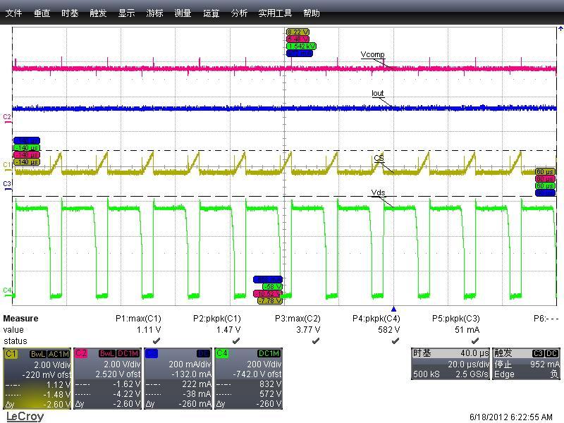
13 9. Waveforms and Testing Results 9.1 Drain Voltage and Current Sense Startup --(Red Vcomp,Blue Vout,Yellow Vcs,Green Vds) Fig.2 Startup 90VAC, 42V load Fig.3 Startup 115VAC 42V load Fig.4 Startup 230VAC, 42V load Fig.5 Startup 264VAC 42V load 9.2 Drain Voltage and Current Sense Nomal Operation --(Red Vcomp,Blue Iout,Yellow Vcs,Green Vds) Fig.6 90VAC, 42V load Fig. 7 90VAC 42V load SiFirst Technology SiFirst_RDR_SFL900_V1.0


14 Fig.8 115VAC, 42V load Fig.9 115VAC, 42V load Fig VAC, 42V load Fig VAC, 42V load Fig VAC, 42V load Fig VAC, 42V load SiFirst Technology SiFirst_RDR_SFL900_V1.0

15 9.3 Ripple and Noise Input Voltage Ripple & Noise Ripple current Ripple Voltage Waveform 90VAC/60Hz 116mA 3.8V Fig VAC/60Hz 108mA 3.5V Fig VAC/50Hz 118mA 3.8V Fig VAC/50Hz 124mA 3.8V Fig.17 Note: Ripple and noise are measured at cable end with a 0.1uF/50V ceramic cap connected in parallel with a 47uF/50V aluminum electrolytic cap. The oscilloscope bandwidth is limited to 20MHz. Fig.14 Ripple & 42V load (Blue Iout,Red Vout) Fig.15 Ripple & 115VAC/60Hz, 42V load (Blue Iout,Red Vout) Fig.16 Ripple & 42V load (Blue Iout,Red Vout) Fig.17 Ripple & 264VAC/50Hz, 42V load (Blue Iout,Red Vout) SiFirst Technology SiFirst_RDR_SFL900_V1.0
 Fig.")
 Max.")

16 9.4 Output current overshoot Input Voltage Measure Data (%) SPEC Waveform 90VAC/60Hz 0 <5% Fig VAC/50Hz 0 <5% Fig.19 Fig.18 90VAC, 42V load (Blue Iout,Red Vout) Fig VAC, 42V load(blue Iout,Red Vout) 9.5 Max Mosfet Vds and second diode Vak Voltage Test Condition Max. Vds (V) Max. Vak(V) Remark Full load 264V/50hz Normal full 264V/50Hz Output 264V/50Hz Fig Fig Fig.22 Fig.20 Startup 264VAC, 42V load Fig.21 Normal 264VAC 42V load SiFirst Technology SiFirst_RDR_SFL900_V1.0


17 Fig.22 Output short 264VAC, 42V load Fig.23 Output short 264VAC, 42V load 10. Protections 10.1 Output Short Circuit Protection --(Red Vcomp,Blue Vcc,Yellow Vcs,Green Vds) Fig.24 output short 90VAC, 42V load Fig.25 output short 90VAC 42V load Fig.26 output short 264VAC, 42V load Fig.27 output short 264VAC 42V load SiFirst Technology SiFirst_RDR_SFL900_V1.0

18 10.2 Over Voltage Protection -- Blue Vout,Yellow Vdem Input Voltage Vout (V) Vdem (V) Waveform 90VAC/60Hz Fig VAC/50Hz Fig.30 Fig.28 90VAC no load Fig.29 90VAC no load Fig VAC no load Fig VAC no load SiFirst Technology SiFirst_RDR_SFL900_V1.0
19 11. EMI Testing Results 11.1 Conduction EMI Test Full Load Report VIN=230V/50Hz, Line (Blue QP yellow--av ) VIN=230V/50Hz, Neutral (Blue QP yellow--av ) FCC 15 Class Full Load Report VIN=120V/60Hz, Line (QP ) VIN=120V/60Hz, Line (AV ) SiFirst Technology SiFirst_RDR_SFL900_V1.0
20 VIN=120V/60Hz, Neutral (QP ) VIN=120V/60Hz, Neutral (AV ) 11.2 Radiation EMI Test Radiation EN55022 CLASS full load report VIN=230V/50Hz, Vertical VIN=230V/50Hz, Horizontal SiFirst Technology SiFirst_RDR_SFL900_V1.0
21 Radiation FCC 15 CLASS full load report VIN=120V/60Hz, Vertical VIN=120V/60Hz, Horizontal IMPORTANT NOTICE SiFirst Technology Nanhai, Ltd (SiFirst) reserves the right to make corrections, modifications, enhancements, improvements and other changes to its products and services at any time and to discontinue any product or service without notice. Customers should obtain the latest relevant information before placing orders and should verify that such information is current and complete. SiFirst Technology SiFirst_RDR_SFL900_V1.0
5V/550mA Battery Charger Solution Using AP3703
 System Engineering Department BCD Semiconductor Manufacturing Limited 01/19/2009 Summary of Report Specifications 85~264Vac, 5V/550mA Applications Key features Cellphone charger or adapter Primary Side
DIO8650 buck boost-80v235ma- THD<5% for LED T-tube lighting
 DEMO EVALUATION REPORT DIO8650 buck boost-80v235ma- THD
6.5W LED Driver Using UPSR100
 6.5W LED Driver Using UPSR00 Subject UPSR00 6 LED Driver Demo Board Manual- Hi Line Version Key features: AC Input Range80Vac/50Hz~264Vac/50Hz DC Output 9Vdc / 0.35A Average Efficiency >79% Short Circuit
Description. Quick Start. Features. Ordering Information. Applications. or call
 Description LED PAR IS31LT3932 is a universal LED driver, which can operate in fly-back, buck-boost and buck convertor. For isolation fly-back, it can achieve high PF, high current accuracy, ± 5 % load
Dimmable LED Driver with iw3614. (Input 230Vac Output 24V350mA)
") Dimmable LED Driver with iw3614 (Input 230Vac Output 24V350mA) 1. Design Purpose and Feature Isolated ac-dc offline, Input 230Vac, Output 7 LEDs 350mA Intelligent wall dimmer detections - Leading-edge
Dimmable LED Driver with iw3614 (Input 230Vac Output 24V350mA) 1. Design Purpose and Feature Isolated ac-dc offline, Input 230Vac, Output 7 LEDs 350mA Intelligent wall dimmer detections - Leading-edge
6.5W LED Driver Using UPSR100
 6.5W LED Driver Using UPSR00 Subject UPSR00 LED Driver Demo Board Manual- Low Line Key features: AC Input Range 90Vac/60Hz~32Vac60/Hz DC Output 2Vdc / 0.3A Average Efficiency > 76% Short Circuit Protection
Test Report. 10W/5V/2A AC/DC Adapter. Reference Design Using UCC28700
 Test Report 0W/5V/2A AC/DC Adapter Reference Design Using UCC28700 Table of Content Introduction... 3 2 Electrical Performance Specifications... 3 3 Schematic... 4 4 Function Test Report... 5 4. Test Equipment...
iw for 9V2A Adapter Design
 iw70-0 for 9VA Adapter Design General Design Specification :. AC Input Range 90-6Vac. DC Output 9V, A 3. Meet EPA_.0 Requirement with 0AWG/.8m DC-Cable. Max Ripple
12V-65W WIDE-RANGE INPUT MAINS ADAPTER USING THE L6566B
 APPLICATION NOTE 12V-65W WIDE-RANGE INPUT MAINS ADAPTER USING THE L6566B Introduction This note describes the characteristics and the features of a 65 W reference board, wide-range input mains, AC-DC adapter
EV4034-S-00B 85VAC-265VAC/50Hz, 10V/350mA Primary-Side-Controlled, Offline, LED Driver Evaluation Board
 EV4034-S-00B 85VAC-265VAC/50Hz, 10V/350mA Primary-Side-Controlled, Offline, LED Driver Evaluation Board DESCRIPTION The EV4034-S-00B Evaluation Board demonstrates the capabilities of the MP4034: a primary-side-controlled,
Reference Design EBC iw1760b-00 for 15W Dual Output Home Appliance Switched Mode Power Supply Design
 Reference Design iw1760b-00 for 15W Dual Output Home Appliance Switched Mode Power Supply Design Table of Contents iw1760b-00 for 15W Dual Output Home Appliance Switched Mode Power Supply Design 1.0. Introduction...3
BF1556 For 5V1A Charger Design
 BF1556 For 5V1A Charger Design Table of Contents BF1556 for High efficiency Charger Design: (AC Input 90-264Vac,Output 5V 1A, No-Load Standby Power
Reference Design EBC iw for 12V 600mA Network Adapter Design
 Reference Design EBC10011 iw1706-00 for 12V 600mA Network Adapter Design Table of Contents iw1706-00 For Network Adapter Design (AC Input 90 264V AC, Output 12V 600mA) EBC10011 1.0. Introduction...3 2.0.
SD6857_AN03 SD6857 DEMO BOARD USER MANUAL
 Silan SD6857 DEMO BOARD USER MANUAL Silan reserves the right to make changes without notice in this specification for the improvement of the design and performance. Silan will supply the best possible
Application Note, V2.0, March 2006 EVALPFC2-ICE1PCS W PFC Evaluation Board with CCM PFC controller ICE1PCS01. Power Management & Supply
 Application Note, V2.0, March 2006 EVALPFC2-ICE1PCS01 300W PFC Evaluation Board with CCM PFC controller ICE1PCS01 Power Management & Supply N e v e r s t o p t h i n k i n g. Edition 2006-03-27 Published
EV4021A-S-00D Universal input, 24W Primary-side-control with Active PFC T8 Isolated LED Driver Evaluation Board
 EV4021A-S-00D Universal input, 24W Primary-side-control with Active PFC T8 Isolated LED Driver Evaluation Board DESCRIPTION The EV4021A-S-00D Evaluation Board is designed for driving a nominal LED string
Application Note, V1.1, October 2009 EVALPFC2-ICE2PCS W PFC Evaluation Board with CCM PFC controller ICE2PCS01. Power Management & Supply
 Application Note, V1.1, October 2009 EVALPFC2-ICE2PCS01 300W PFC Evaluation Board with CCM PFC controller ICE2PCS01 Power Management & Supply N e v e r s t o p t h i n k i n g. Edition 2009-10-13 Published
Reference Design EBC941. Dimmable LED Driver with iw (AC input 180V 264V AC. , Output 30V 350mA)
") Reference Design Dimmable LED Driver with iw3616-01 (AC input 180V 264V AC Table of Contents Dimmable LED Driver with iw3616-01 1.0. Introduction...3 2.0. Design Features...3 3.0. Design Specification...4
Reference Design Dimmable LED Driver with iw3616-01 (AC input 180V 264V AC Table of Contents Dimmable LED Driver with iw3616-01 1.0. Introduction...3 2.0. Design Features...3 3.0. Design Specification...4
Reference Design EBC940. Dimmable LED Driver with iw (AC Input 90V 135V AC. , Output 30V 350mA)
") Reference Design Dimmable LED Driver with iw3616-00 (AC Input 90V 135V AC Table of Contents Dimmable LED Driver with iw3616-00 1.0. Introduction...3 2.0. Design Features...3 3.0. Design Specification...4
Reference Design Dimmable LED Driver with iw3616-00 (AC Input 90V 135V AC Table of Contents Dimmable LED Driver with iw3616-00 1.0. Introduction...3 2.0. Design Features...3 3.0. Design Specification...4
EV020-5-S-01B 85VAC~265VAC/50Hz, 12V/0.65A,5V/50mA Off-line Primary-Side-Regulator Home Appliances Evaluation Board
 The Future of Analog IC Technology EV020-5-S-01B 85VAC~265VAC/50Hz, 12V/0.65A,5V/50mA Off-line Primary-Side-Regulator Home Appliances Evaluation Board DESCRIPTION The EV020-5-S-01B Evaluation Board is
ANP030. Contents. Application Note AP2014/A Synchronous PWM Controller. 1. AP2014/A Specification. 2. Hardware. 3. Design Procedure. 4.
 Contents 1. AP2014/A Specification 1.1 Features 1.2 General Description 1.3 Pin Assignments 1.4 Pin Descriptions 1.5 Block Diagram 1.6 Absolute Maximum Ratings 2. Hardware 2.1 Introduction 2.2 Description
Universal AC input, Primary Side Regulation AP3983E 12V-1.5A EV1 Board User Guide
 Universal AC input, Primary Side Regulation General Description Based on Flyback topology, the Primary side Regulated AP3983E EV1 board is designed to serve as an example for High Efficiency, low cost
EV S-00A Primary Side CC/CV Flyback Regulator Universal Input, 5V/2A USB Charger Evaluation Board
 The Future of Analog IC Technology EV24-1-S-A Primary Side CC/CV Flyback Regulator Universal Input, 5V/2A USB Charger Evaluation Board DESCRIPTION The MP24-1 is a low cost offline primary-side Flyback
AT V,3A Synchronous Buck Converter
 FEATURES DESCRIPTION Wide 8V to 40V Operating Input Range Integrated 140mΩ Power MOSFET Switches Output Adjustable from 1V to 25V Up to 93% Efficiency Internal Soft-Start Stable with Low ESR Ceramic Output
160W PFC Evaluation Board with DCM PFC controller TDA and CoolMOS
 Application Note Version 1.0 160W PFC Evaluation Board with DCM PFC controller TDA4863-2 and CoolMOS SPP08N50C3 Power Management & Supply TDA4863-2 SPP08N50C3 Ver1.0, _doc_release> N e v e
30V, 3.1A Monolithic Step-Down Switching Regulator. C5 100nF/25V 5 FB COMP GND 4. Fig. 1 Schematic 60.00%
 30V, 3.1A Monolithic Step-Down Switching Regulator 1 Features 3.1A continuous output current capability 6.5V to 30V wide operating input range with input Over Voltage Protection Integrated 36V, 79mΩ high
AC - DC 150W LED Driver MDC150 Single Output Series
 Features Built-in 10KV lightning surge protection (EN61000-4-5) 90 ~ 305Vac full range input; Active PFC Output voltage range up to 58Vdc for outdoor lighting Aluminum case IP65/ IP67 waterproof Dual mode
Boundary Mode Offline LED Driver Using MP4000. Application Note
 The Future of Analog IC Technology AN046 Boundary Mode Offline LED Driver Using MP4000 Boundary Mode Offline LED Driver Using MP4000 Application Note Prepared by Zheng Luo March 25, 2011 AN046 Rev. 1.0
LSP5502 2A Synchronous Step Down DC/DC Converter
 FEATURES 2A Output Current Wide 4.5V to 27V Operating Input Range Integrated 20mΩ Power MOSFET Switches Output Adjustable from 0.925V to 24V Up to 96% Efficiency Programmable Soft-Start Stable with Low
HM V, 3.1A Monolithic Buck Converter with Port Controller. 1 Features. 2 Applications. 3 Description. 4 Typical Application Schematic.
 30V, 3.1A Monolithic Buck Converter with Port Controller HM1498. 1 Features 3.1A continuous output current capability 6.5V to 30V wide operating input range with input Over Voltage Protection Up to 96%
30W PD Power Module Using UCS1655S+VP300
 UCS655S+VP300 30W PD Power EVB Manual Key features: Compatible VIA PD protocol AC Input Full Range 90Vac~264Vac DC Output (Default voltage 5V) 5V 3 A 9V 3 A 2V 2.5 A 5V 2 A 20V.5 A Average Efficiency (Board
Supertex inc. HV9971DB1. Isolated, Constant Current HV9971 LED Driver Demoboard. Board Layout and Connection Diagram.
 Isolated, Constant Current HV9971 LED Driver Demoboard Board Layout and Connection Diagram Terminals for Monitoring Bus Voltage - + V AC = + 180-265VAC = 18-24V - I OUT = 330mA Connections 1. Input Voltage:
IS31LT3916. Isolated or Non-isolated configuration LED driver with active PFC. January General Description. Features
 Isolated or Non-isolated configuration LED driver with active PFC General Description Features January 2013 The IS31LT3916 is a primary side, peak current mode, isolated or non-isolated type HBLED driver.
AC - DC 96W LED Driver MDC100 Single Output Series
 AC - DC LED Driver Features Built-in 10KV lightning surge protection (EN61000-4-5) 90 ~ 305Vac full range input; Active PFC Output voltage range up to 58Vdc for outdoor lighting Aluminum case IP65/ IP67
Power Management & Supply. Design Note. Version 2.3, August 2002 DN-EVALSF2-ICE2B765P-1. CoolSET 80W 24V Design Note for Adapter using ICE2B765P
 Version 2.3, August 2002 Design Note DN-EVALSF2-ICE2B765P-1 CoolSET 80W 24V Design Note for Adapter using ICE2B765P Author: Rainer Kling Published by Infineon Technologies AG http://www.infineon.com/coolset
Reference Design EBC iw for 5V 1A Mini-TA Charger Design
 Reference Design EBC10010 iw1700-01 for 5V 1A Mini-TA Charger Design Table of Contents iw1700-01 For Mini-TA Charger Design (AC Input 90 264V AC, Output 5V 1A) EBC10010 1.0. Introduction...3 2.0. Design
D W PI Product description: Product feature: Application Circuit Diagram: PSR+SPFC LED bulb lamp driver
 PI186101 Product description: PSR+SPFC LED bulb lamp driver Product feature: 1. PF>0.9, Eff.>0.85, full voltage 85Vac-265Vac input 2. Constant current driver, constant current precision ±3%, Open /short
HM V, 3.1A Monolithic Step-Down Switching Regulator in TSOT Features. 2 Applications. 3 Description. 4 Typical Application Schematic
 30V, 3.1A Monolithic Step-Down Switching Regulator in TSOT23-8 1 Features 3.0A continuous output current capability 6.5V to 30Vwide operating input range with input Over Voltage Protection Integrated 36V,
Reference Design EBC iw for 5V 1A Small-Size Adapter Design
 Reference Design EBC10003 iw1677-00 for 5V 1A Small-Size Adapter Design Table of Contents iw1677-00 For Small-Size Adapter Design (AC Input 90 264V AC, Output 5V 1A) EBC10003 1.0. Introduction...3 2.0.
23V, 3A, 340KHz Synchronous Step-Down DC/DC Converter
 23V, 3A, 340KHz Synchronous Step-Down DC/DC Converter Description The is a synchronous step-down DC/DC converter that provides wide 4.5V to 23V input voltage range and 3A continuous load current capability.
Constant Current Switching Regulator for White LED
 Constant Current Switching Regulator for White LED FP7201 General Description The FP7201 is a Boost DC-DC converter specifically designed to drive white LEDs with constant current. The device can support
AT V Synchronous Buck Converter
 38V Synchronous Buck Converter FEATURES DESCRIPTION Wide 8V to 38V Operating Input Range Integrated two 140mΩ Power MOSFET Switches Feedback Voltage : 220mV Internal Soft-Start / VFB Over Voltage Protection
Design Guideline and Application Notes of AP1681 System Solution
 Design Guideline and Application otes of AP1681 System Solution Prepared by Wang Zhao Kun System Engineering Dept. 1. ntroduction The AP1681 is a powerful high performance AC/DC power supply controller
AN2001 Application note
 Application note VIPower : the VIPer53-E single output reference board with 90 to 264 Vac input, 24 W output Introduction The VIPer53-E combines an enhanced current mode PWM controller with a high voltage
AN2447 Application note
 Application note Quasi-resonant flyback converter for low cost set-top box application Introduction This application note describes how to implement a complete solution for a 17 W switch mode power supply
Non-Synchronous PWM Boost Controller
 Non-Synchronous PWM Boost Controller FP5209 General Description The FP5209 is a boost topology switching regulator for wide operating voltage applications. It provides built-in gate driver pin, EXT pin,
Application Note, V1.0, Nov 2004 ICE3B2565. SMPS Evaluation Board with CoolSET TM ICE3B2565. Power Management & Supply
 Application Note, V1.0, Nov 2004 ICE3B2565 SMPS Evaluation Board with CoolSET TM ICE3B2565 F3 Power Management & Supply N e v e r s t o p t h i n k i n g. Edition 2005-01-13 Published by Infineon Technologies
AC - DC 120~150W LED Driver MDC120 Single Output Series
 Features Built-in 10KV lightning surge protection (EN61000-4-5) 90 ~ 305Vac full range input; Active PFC Output voltage range up to 430Vdc for outdoor lighting Aluminum case IP65/ IP67 waterproof Dual
Low Cost 8W Off-line LED Driver using RT8487
 Application Note AN019 Jun 2014 Low Cost 8W Off-line LED Driver using RT8487 Abstract RT8487 is a boundary mode constant current controller with internal high side driver, which can be used in buck and
Application Note. EVALQS-190W-ICE2QS02G 190W Evaluation Board Based on Quasi-resonant Flyback Converter for LCD TV SMPS. Power Management & Supply
 Application Note, V1.1, 2 February 2009 Application Note EVALQS-190W-ICE2QS02G 190W Evaluation Board Based on Quasi-resonant Flyback Converter for LCD TV SMPS Power Management & Supply N e v e r s t o
AL1672EV1 User Guide 100~265VAC High PF Buck LED Driver
 General Description This demonstration board utilizes the AL1672 Buck LED driver IC providing a cost effective PWM/Analog dimmable solution for offline high brightness LED applications. This user-friendly
30W PD Power Module Using UCS1655S+VP300
 UCS655S+VP300 30W PD Power EVB Manual Key features: Compatible VIA PD protocol AC Input Full Range 90Vac~64Vac DC Output (Default voltage 5V) 5V 3 A 9V 3 A V.5 A 5V A 0V.5 A Average Efficiency (Board end)
HM2259D. 2A, 4.5V-20V Input,1MHz Synchronous Step-Down Converter. General Description. Features. Applications. Package. Typical Application Circuit
 HM2259D 2A, 4.5V-20V Input,1MHz Synchronous Step-Down Converter General Description Features HM2259D is a fully integrated, high efficiency 2A synchronous rectified step-down converter. The HM2259D operates
Low-Noise 4.5A Step-Up Current Mode PWM Converter
 Low-Noise 4.5A Step-Up Current Mode PWM Converter FP6298 General Description The FP6298 is a current mode boost DC-DC converter. It is PWM circuitry with built-in 0.08Ω power MOSFET make this regulator
UNISONIC TECHNOLOGIES CO., LTD UC1103 Preliminary CMOS IC
 UNISONIC TECHNOLOGIES CO., LTD HIGH PRECISION CC/CV PRIMARY SIDE SWITCHING REGULATOR DESCRIPTION The UTC UC1103 is a primary control unit for switch mode charger and adapter applications. The controlled
Green-Mode PWM Controller with Integrated Protections
 Green-Mode PWM Controller with Integrated Protections Features Current mode control Very low startup current Under-voltage lockout (UVLO) Non-audible-noise green-mode control Programmable switching frequency
Analog Technologies. ATI2202 Step-Down DC/DC Converter ATI2202. Fixed Frequency: 340 khz
 Step-Down DC/DC Converter Fixed Frequency: 340 khz APPLICATIONS LED Drive Low Noise Voltage Source/ Current Source Distributed Power Systems Networking Systems FPGA, DSP, ASIC Power Supplies Notebook Computers
HF A 27V Synchronous Buck Converter General Description. Features. Applications. Package: TBD
 General Description The is a monolithic synchronous buck regulator. The device integrates 80 mω MOSFETS that provide 4A continuous load current over a wide operating input voltage of 4.5V to 27V. Current
4.5V to 32V Input High Current LED Driver IC For Buck or Buck-Boost Topology CN5816. Features: SHDN COMP OVP CSP CSN
 4.5V to 32V Input High Current LED Driver IC For Buck or Buck-Boost Topology CN5816 General Description: The CN5816 is a current mode fixed-frequency PWM controller for high current LED applications. The
ISL6721EVAL Current Mode Active Clamp Forward with SR for Middle Power Level Applications
 ISL6721EVAL Current Mode Active Clamp Forward with SR for Middle Power Level Applications Introduction: The ISL6721EVAL board is a 48V input to 3.3V output DC/DC converter which can output current up to
AC - DC 96W LED Driver MDC100 Single Output Series
 Features Built-in 10KV lightning surge protection (EN61000-4-5) 90 ~ 305Vac full range input; Active PFC Output voltage range up to 58Vdc for outdoor lighting Aluminum case IP65/ IP67 waterproof Dual mode
DESCRIPTION FEATURES APPLICATIONS TYPICAL APPLICATION. 500KHz, 18V, 2A Synchronous Step-Down Converter
 DESCRIPTION The is a fully integrated, high-efficiency 2A synchronous rectified step-down converter. The operates at high efficiency over a wide output current load range. This device offers two operation
1.0MHz,24V/2.0A High Performance, Boost Converter
 1.0MHz,24V/2.0A High Performance, Boost Converter General Description The LP6320C is a 1MHz PWM boost switching regulator designed for constant-voltage boost applications. The can drive a string of up
Single Switch Forward Converter
 Single Switch Forward Converter This application note discusses the capabilities of PSpice A/D using an example of 48V/300W, 150 KHz offline forward converter voltage regulator module (VRM), design and
AN2103 APPLICATION NOTE VIPower: VIPer12A ISOLATED FLYBACK CONVERTER REFERENCE BOARD
 AN203 APPLICATION NOTE VIPower: VIPer2A ISOLATED FLYBACK CONVERTER REFERENCE BOARD. ABSTRACT The presented circuit can be used to produce multiple isolated voltage outputs. It is dedicated to building
RT7306 Evaluation Board
 RT7306 Purpose The RT7306 is a constant current LED driver with active power factor correction. It supports high power factor across a wide range of line voltages, and it drivers the converter in the Quasi-resonant
FL7732 Single-Stage PFC Primary-Side-Regulation Offline LED Driver
 FL7732 Single-Stage PFC Primary-Side-Regulation Offline LED Driver Features Cost-Effective Solution: No Input Bulk Capacitor or Feedback Circuitry Power Factor Correction Accurate Constant-Current (CC)
AN-EVALSF3-ICE3B0565J
 Application Note, V1.0, Sep 2005 AN-EVALSF3-ICE3B0565J 12W 5.0V SMPS Evaluation Board with CoolSET TM F3 ICE3B0565J Power Management & Supply N e v e r s t o p t h i n k i n g. Edition 2005-09-26 Published
Keywords: No-opto flyback, synchronous flyback converter, peak current mode controller
 Keywords: No-opto flyback, synchronous flyback converter, peak current mode controller APPLICATION NOTE 6394 HOW TO DESIGN A NO-OPTO FLYBACK CONVERTER WITH SECONDARY-SIDE SYNCHRONOUS RECTIFICATION By:
AC-DC SMPS: Up to 15W Application Solutions
 AC-DC SMPS: Up to 15W Application Solutions Yehui Han Applications Engineer April 2017 Agenda 2 Introduction Flyback Topology Optimization Buck Topology Optimization Layout and EMI Optimization edesignsuite
idesyn id8802 2A, 23V, Synchronous Step-Down DC/DC
 2A, 23V, Synchronous Step-Down DC/DC General Description Applications The id8802 is a 340kHz fixed frequency PWM synchronous step-down regulator. The id8802 is operated from 4.5V to 23V, the generated
JW1767B FEATURES DESCRIPTION APPLICATIONS TYPICAL APPLICATION. Offline Step-down LED Regulator With PFC and High Voltage MOSFET
 JW767B Offline Step-down LED Regulator With PFC and High Voltage MOSFET Parameters Subject to Change Without Notice FEATURES No auxiliary winding 600V high voltage MOSFET integrated High current accuracy
FEB User s Guide Power Factor Corrected 500W Off-Line Power Supply
 FEB108-001 User s Guide Power Factor Corrected 500W Off-Line Power Supply Featured Fairchild Product: FAN4810 www.fairchildsemi.com/febsupport Contents 1. General Board Description...3 1.1 Contents of
AL1663-Flyback-30V650mA User Guide 85v~265VAC Evaluation
 General Description This demonstration board utilizes the AL1663 Flyback LED driver-controller providing a cost effective solution for high brightness LED applications. This userfriendly evaluation board
Design Example Report
 Design Example Report Title Specification Application Author Document Number 9W power supply using TNY267P Input: 85 265 VAC Output: 5V/0.56A, 3.3V/0.48A, 12V/100mA, -12V/15mA, -22V/100mA, Floating 4V/100mA
Evaluation Board for ADP2118 EVAL-ADP2118
 Evaluation Board for ADP8 EVAL-ADP8 GENERAL DESCRIPTION The evaluation (demo) board provides an easy way to evaluate the ADP8 buck regulator. This data sheet describes how to quickly set up the board to
DESCRIPTION FEATURES APPLICATIONS TYPICAL APPLICATION
 MP5016 2.7V 22V, 1A 5A Current Limit Switch with Over Voltage Clamp and Reverse Block The Future of Analog IC Technology DESCRIPTION The MP5016 is a protection device designed to protect circuitry on the
SPECIFICATION. LED Driver. Model : SI-EPF006650WW CUSTOMER : SAMSUNG CHECKED APPROVED DRAWN SAMSUNG #2, NONGSEO-DONG, GIHEUNG-GU,
 01 1 /17 SPECIFICATION Model : SI-EPF006650WW CUSTOMER : CHECKED APPROVED 20... 20... SAMSUNG DRAWN SALES CHECKED QA APPROVED 20... 20... 20... 20... SAMSUNG ELECTRONICS CO,. LTD. SAMSUNG #2, NONGSEO-DONG,
Notes: Note1: Max. capacitive load is tested at nominal input voltage and full load. Single or Dual
 Features Regulated Converters Description 6-Side Shielding External ON/OFF control 1.6kV Isolation UL/CSA/EN-695-1 Certified 2:1 Input Voltage Range Continuous Short Circuit Protection Efficiency up to
EVALPFC-300W-ICE3PCS02/03G
 Application Note, V1.0, January 2011 EVALPFC-300W-ICE3PCS02/03G 300W PFC Evaluation Board with CCM PFC controller ICE3PCS02/03G Power Management & Supply N e v e r s t o p t h i n k i n g. Edition 2010-12-31
SPECIFICATION FOR APPROVAL
 Scanning LIB. SPECIFICATION FOR APPROVAL CUSTOMER : ITEM : Power Supply Unit. DESCRIPTION : LCD & LED Monitor Power Supply. CUSTOMER P/NO : SUPPLIER P/NO : BRK-3500 DATE : 2015-10-05 CUSTOMER EN GR CHKD
1.5MHz, 3A Synchronous Step-Down Regulator
 1.5MHz, 3A Synchronous Step-Down Regulator FP6165 General Description The FP6165 is a high efficiency current mode synchronous buck PWM DC-DC regulator. The internal generated 0.6V precision feedback reference
FEBFL7733A_L50U008A Evaluation Board. 8.4 W LED Driver at Universal Line. Featured Fairchild Product: FL7733A
 User Guide for FEBFL7733A_L50U008A Evaluation Board 8.4 W LED Driver at Universal Line Featured Fairchild Product: FL7733A Direct questions or comments about this evaluation board to: Worldwide Direct
Green-Mode PWM Controller with Integrated Protections
 Green-Mode PWM Controller with Integrated Protections Features High-voltage (500) startup circuit Current mode PWM ery low startup current (
High performance ac-dc notebook PC adapter meets EPA 4 requirements
 High performance ac-dc notebook PC adapter meets EPA 4 requirements Alberto Stroppa, Claudio Spini, Claudio Adragna STMICROELECTRONICS via C. Olivetti Agrate Brianza (MI), Italy Tel.: +39/ (039) 603.6184,
MP2494 2A, 55V, 100kHz Step-Down Converter
 The Future of Analog IC Technology MP2494 2A, 55V, 100kHz Step-Down Converter DESCRIPTION The MP2494 is a monolithic step-down switch mode converter. It achieves 2A continuous output current over a wide
RT8487. High Efficiency BCM LED Driver Controller for High Power Factor Offline Applications. General Description. Features. Ordering Information
 High Efficiency BCM LED Driver Controller for High Power Factor Offline Applications General Description The RT8487 is a Boundary mode high PF floating buck constant LED current output controller with
1.5MHz, 2A Synchronous Step-Down Regulator
 1.5MHz, 2A Synchronous Step-Down Regulator General Description The is a high efficiency current mode synchronous buck PWM DC-DC regulator. The internal generated 0.6V precision feedback reference voltage
AL1696EV1 User Guide 120VAC Dimmable LED Driver
 120VAC Dimmable LED Driver General Description This demonstration board utilizes the AL1696 Buck LED driver providing a cost effective triac dimmable solution for offline high brightness LED applications.
UCC38C42 25-Watt Self-Resonant Reset Forward Converter Reference Design
 Reference Design UCC38C42 25-Watt Self-Resonant Reset Forward Converter Reference Design UCC38C42 25-Watt Self-Resonant Reset Forward Converter Lisa Dinwoodie Power Supply Control Products Contents 1 Introduction.........................................................................
AN2000 Application note
 Application note VIPower: VIPer53A dual output reference board 90 to 264 VAC input, 24W output Introduction This is an off-line wide range VIPer53 dual output reference board that is set up for secondary
DN0039 Design note. 35 W wide input range flyback converter using HVLED001A quasi resonant Flyback controller and STF10LN80K5.
 DN0039 Design note 35 W wide input range flyback converter using HVLED001A quasi resonant Flyback controller and STF10LN80K5 Designs from our labs describe tested circuit designs from ST labs which provide
FEBFSL336LRN_CS04U07A Evaluation Board. Fairchild Multi-Output Buck Converter. Featured Fairchild Product: FSL336LRN
 User Guide for FEBFSL336LRN_CS04U07A Evaluation Board Fairchild Multi-Output Buck Converter Featured Fairchild Product: FSL336LRN Direct questions or comments about this evaluation board to: Worldwide
CEP8101A Rev 1.0, Apr, 2014
 Wide-Input Sensorless CC/CV Step-Down DC/DC Converter FEATURES 42V Input Voltage Surge 40V Steady State Operation Up to 2.1A output current Output Voltage 2.5V to 10V Resistor Programmable Current Limit
LD /15/2011. Green-Mode PWM Controller with Frequency Swapping and Integrated Protections. Features. General Description.
 12/15/2011 Green-Mode PWM Controller with Frequency Swapping and Integrated Protections Rev. 02a General Description The LD7536 is built-in with several functions, protection and EMI-improved solution
FEBFL7732_L25U008B. 8.4 W LED Driver at Universal Line. Featured Fairchild Product: FL7732
 User Guide for FEBFL7732_L25U008B 8.4 W LED Driver at Universal Line Featured Fairchild Product: FL7732 Direct questions or comments about this evaluation board to: Worldwide Direct Support Fairchild Semiconductor.com
3 in 1 Dimmable (0-10Vdc, PWM signal, or resistance)
") FEATURES: AC Input 100~277VAC Built-in Active PFC Function Protection: SCP / OVP / OTP 12V Auxiliary Output Built-in 3 in 1 dimming function (0-10Vdc, 10V PWM signal, or resistance) Power saving < 0.35W
FEATURES: AC Input 100~277VAC Built-in Active PFC Function Protection: SCP / OVP / OTP 12V Auxiliary Output Built-in 3 in 1 dimming function (0-10Vdc, 10V PWM signal, or resistance) Power saving < 0.35W
EUP3452A. 2A,30V,300KHz Step-Down Converter DESCRIPTION FEATURES APPLICATIONS. Typical Application Circuit
 2A,30V,300KHz Step-Down Converter DESCRIPTION The is current mode, step-down switching regulator capable of driving 2A continuous load with excellent line and load regulation. The can operate with an input
EUP V/12V Synchronous Buck PWM Controller DESCRIPTION FEATURES APPLICATIONS. Typical Application Circuit. 1
 5V/12V Synchronous Buck PWM Controller DESCRIPTION The is a high efficiency, fixed 300kHz frequency, voltage mode, synchronous PWM controller. The device drives two low cost N-channel MOSFETs and is designed
CEP8113A Rev 2.0, Apr, 2014
 Wide-Input Sensorless CC/CV Step-Down DC/DC Converter FEATURES 42V Input Voltage Surge 40V Steady State Operation Up to 3.5A output current Output Voltage 2.5V to 10V Resistor Programmable Current Limit