AN-EVALSF3-ICE3B0565J
|
|
|
- Gervase Harmon
- 5 years ago
- Views:
Transcription
1 Application Note, V1.0, Sep 2005 AN-EVALSF3-ICE3B0565J 12W 5.0V SMPS Evaluation Board with CoolSET TM F3 ICE3B0565J Power Management & Supply N e v e r s t o p t h i n k i n g.
2 Edition Published by Infineon Technologies Asia Pacific, 168 Kallang Way, Singapore, Singapore Infineon Technologies AP All Rights Reserved. Attention please! The information herein is given to describe certain components and shall not be considered as a guarantee of characteristics. Terms of delivery and rights to technical change reserved. We hereby disclaim any and all warranties, including but not limited to warranties of non-infringement, regarding circuits, descriptions and charts stated herein. Information For further information on technology, delivery terms and conditions and prices please contact your nearest Infineon Technologies Office ( Warnings Due to technical requirements components may contain dangerous substances. For information on the types in question please contact your nearest Infineon Technologies Office. Infineon Technologies Components may only be used in life-support devices or systems with the express written approval of Infineon Technologies, if a failure of such components can reasonably be expected to cause the failure of that life-support device or system, or to affect the safety or effectiveness of that device or system. Life support devices or systems are intended to be implanted in the human body, or to support and/or maintain and sustain and/or protect human life. If they fail, it is reasonable to assume that the health of the user or other persons may be endangered.
3 Revision History: V1.0 Previous Version: none Page Subjects (major changes since last revision) 12W 5.0V SMPS Evaluation Board with CoolSET TM F3 ICE3B0565J: License to Infineon Technologies Asia Pacific Pte Ltd ANP0065 Kok Siu Kam Eric Jeoh Meng Kiat We Listen to Your Comments Any information within this document that you feel is wrong, unclear or missing at all? Your feedback will help us to continuously improve the quality of this document. Please send your proposal (including a reference to this document) to: ap-lab.admin@infineon.com
4 Table of Contents Page 1 Evaluation Board List of Features Technical Specifications Circuit Diagram PCB Layout Component side component legend Solder side copper & component legend Circuit Description Introduction Line Input Start up Operation mode Soft start Clamper circuit Limitation of primary current Output Stage Feedback and regulation Blanking Window for Load Jump / Active Burst Mode Active Burst Mode Jitter mode Component List Transformer Construction Test Results Efficiency Input Standby Power Line Regulation Load Regulation Max. Overload Output Power Waveforms and Scope Plots Low and High AC Line Input Voltage and 12W load Drain Source Voltage and Current During 12W load Operation Load Transient Response ( Load jump from 10% to 100% Load ) AC Output Ripple during 12W Blanking window for over power protection Active Burst 0.5W load Frequency Jittering Slope compensation...23 Application Note

5 Abstract This document is an engineering report that describes an universal input power supply designed in a typical off line flyback converter topology that utilizes the ICE3B0565J CoolSET TM1. The application operates in discontinuous current mode using the active burst mode during standby condition. The board has one output voltage with secondary regulation. It is especially suitable as an AC/DC power supply for LCD monitors, adapters for printer, notebook computers, DVD players and set-top boxes and auxiliary power for high power system. The ICE3B0565J is an enhanced version of the F3 CoolSET TM. Besides having the basic features of the F3 CoolSET TM such as Active Burst Mode, adjustable blanking time, propagation delay compensation, etc., it also has the BiCMOS technology design and frequency jittering. It can further reduce the input Standby Power and at the same time achieve the low EMI performance. 1 Evaluation Board Figure 1 EVALSF3-ICE3B0565J This document contains the list of features, the power supply specification, schematic, bill of material and the transformer construction documentation. Typical operating characteristics are presented at the rear of the report and consist of performance curves and scope waveforms. 1 CoolSET TM is a current mode PWM control IC and the power MOSFET CoolMOS TM within one package designed for low cost switch mode power supplies (SMPS). Application Note
6 2 List of Features 650V avalanche rugged CoolMOS with built in switchable Startup Cell Active Burst Mode for lowest Standby light load controlled by Feedback signal BiCMOS technology provide wide Vcc voltage range Fast load jump response in Active Burst Mode 67kHz fixed switching frequency Auto Restart Mode for Over temperature protection, Overvoltage protection, Overload protection, Open Loop protection and VCC Undervoltage protection Blanking Window for short duration high current User defined Soft Start Max Duty Cycle 72% Propagation delay compensation provide accurate primary current limit Frequency jittering for low EMI 3 Technical Specifications Input voltage 85VAC~265VAC Input frequency 50Hz, 60Hz Input Standby Power < no load; < 0.5W load Output voltage and current 5V +/- 2% Output current 2.4A Output power 12W Efficiency >75% at full load Output ripple voltage < 50mVp-p ( exclude high frequency spike ) Application Note
7 4 Circuit Diagram C4 2.2nF/250V, Y1 C23 * R21 * L 85V - 265Vac N F1 0.5A C1 0.1uF/275V L1 EMI 2 x 27mH, 0.5A BR1 2KBB40 R k/2W C2 47uF/400V D1 UF4005 C3 2n2F/400V TR1 6 8 D21 SB540 L21 1.5uH + C uF/25V + C22 220uF/25V 5V/2.4A GND C5 24V ZD1 + 22u/25V R2 510R D2 1N C6 0.1u C7 1uF 1 VCC Softst GND 8 7 IC1 ICE3B0565J FB 2 C8 1nF DRAI N DRAI N Isense 3 5 R4 1.5R 4 R4A 15R EF20 IC2 SFH617A Rc6 470 Rc5 2.2K IC3 TL431 Cc2 1nF Rc4 6.8k Cc1 1uF Rc3A * Rc1 10k Rc2 0R Rc3 10k Figure 2 12W 5.0V ICE3B0565J power supply Schemetic Application Note
8 5 PCB Layout 5.1 Component side component legend Figure 3 Component side Component Legend View from Component Side Application Note
9 5.2 Solder side copper & component legend Figure 4 Solder side copper View from Component Side Figure 5 Solder side component Legend View from Component Side Application Note
10 6 Circuit Description 6.1 Introduction The EVALSF3-ICE3B0565J demoboard is a low cost off line flyback switch mode power supply ( SMPS ) using the ICE3B0565J system IC from the CoolSET TM -F3 family. The circuit, shown in Figure 2, details a 5.0V, 12W power supply that operates from an AC line input voltage range of 85Vac to 265Vac, suitable for applications requiring either an open frame supply or an enclosed adapter. 6.2 Line Input The AC line input side comprises the input fuse F1 as over-current protection. The choke L1, X2-capacitors C1 and Y1-capacitor C4 act as radio interference suppressors. After the bridge rectifier BR1 and the input bulk capacitor C2, a voltage of 100 to 380 V DC is present which depends on input voltage is available. 6.3 Start up Since there is a built-in startup cell in the ICE3B0565J, there is no need for external start up resistor. The startup cell is connecting the drain pin of the IC. Once the voltage is built up at the Drain pin of the ICE3B0565J, the startup cell will charge up the Vcc capacitor C5 and C6. When the Vcc voltage exceeds the UVLO at 18V, the IC starts up. Then the Vcc voltage is bootstrapped by the auxiliary winding to sustain the operation. 6.4 Operation mode During operation, the Vcc pin is supplied via a separate transformer winding with associated rectification D2 and buffering C5, C6. Resistor R2 is used for current limiting. In order not to exceed the maximum voltage at Vcc pin an external zener diode ZD1 limits this voltage. 6.5 Soft start The Soft-Start function is realized by an internal resistor and the adjustable external capacitor C Clamper circuit The circuit R1, C3 and D1 clamp the DRAIN voltage spike caused by transformer leakage inductance to a safe value below the drain source break down voltage V DSBR = 650V 1 maximum. 6.7 Limitation of primary current The CoolMOS TM drain source current is sensed via external shunt resistors R4 and R4A. An accurate value of the shunt improves the peak power limitation shown in the curve peak power limitation in the rear of this report. 6.8 Output Stage On the secondary side the power is coupled out by a schottky diode D21. The capacitor C21 provides energy buffering following with the LC filter L21 and C22 to reduce the output voltage ripple considerably. Storage 1 V DSBR = Tj = 110 C Application Note
11 capacitor C21 is selected to have an internal resistance as small as possible (ESR) to minimizes the output voltage ripple 6.9 Feedback and regulation The output voltage is controlled using a type TL431 reference diode (IC3). This device incorporates the voltage reference as well as the error amplifier and a driver stage. Compensation network Cc1, Cc2, Rc1, Rc4 constitutes the external circuitry of the error amplifier of IC3. This circuitry allows the feedback to be precisely matched to dynamically varying load conditions, thereby providing stable control. The maximum current through the optocoupler diode and the voltage reference is set by using resistors Rc5 and Rc6. Optocoupler IC2 is used for floating transmission of the control signal to the Feedback input via capacitor C8 of the ICE3B0565J control device. The optocoupler used meets DIN VDE 884 requirements for a wider creepage distance Blanking Window for Load Jump / Active Burst Mode In case of Load Jumps the Controller provides a Blanking Window before activating the Overvoltage Protection and entering the Auto Restart Mode. This time is generated by charging up the Soft Start capacitor from 3.4V to 4.0V. Within this time frame the voltage at Feedback pin can rise up above 4.5V, without switching off due to Overload Protection. During this operation the transferred power is limited to the maximum peak current defined by the value of the sense resistor. The same procedure happens to the external Soft Start capacitor if a low load condition is detected when V FB is falling below 1.35V. Only after V SOFTS has exceeded 4.0V and V FB is still below 1.35V, Active Burst Mode is entered Active Burst Mode At light load condition, the SMPS enters into Active Burst Mode. The controller is always active at this state. V CC must therefore be above the switch off threshold V CCoff = 10.5V. While supporting low ripple on V OUT and fast response on load jump, efficiency also increased significantly during Active Burst Mode. When the voltage level at FB falls below 1.35V, capacitor C 7 at SOFTS pin is allowed to charge from the sawtooth voltage level at 3.2V ~ 3.6V in Normal Operating Mode. Active Burst Mode is entered if V SOFTS exceeds 4.0V. A Blanking Window as mentioned earlier which can be adjusted by manipulating C 7, is generated to avoid a sudden entering of Burst Mode due to load jump. During Active Burst Mode the current sense voltage limit at I CS pin, V ICS, is set to 0.32V to reduce the conduction losses. All the internal circuits are switched off except the reference and bias voltages to reduce the total V CC current consumption to below 0.5mA. The FB voltage is changing like a sawtooth between 3.2 and 3.6V. To leave Burst Mode, FB voltage must exceed 4.5V. This resets the Active Burst Mode and turns the SMPS into Normal Operating Mode. Maximum current can now be provided to stabilize V OUT Jitter mode The soft start capacitor, C7 has 3 functions; control the soft start time, control the blanking time and control the period of the frequency jitter mode. Once the ICE3B0565J is startup, the SOFTS pin will run at a sawtooth voltage from 3.2V ~ 3.6V. This voltage controls the period of the jitter frequency. The jitter frequency is for ICE3B0565J is internally set at 67KHz +/-2.7KHz. This demo board has SOFTS capacitor of 1uF and the jitter period is around 3.2ms. Application Note
12 7 Component List Items Part Type Quantity 1 BR1 2KBB80R 1 2 C1 0.1uF/275V, X2 Capacitor 1 3 C2 47uF/400V 1 4 C3 2.2nF/400V 1 5 C4 2.2nF/250V, Y1 Capacitor 1 6 C5 22uF/35V 1 7 C6 100nF/50V 1 8 C7 1uF/50V 1 9 C8 1nF/50V 1 10 C uF/25V 1 11 C22 220uF/25V 1 12 C23 N.A Cc1 1uF/50V 1 14 Cc2 1nF/50V 1 15 D1 UF D2 1N D21 SB F1 0.5A/250V 1 19 IC1 ICE3B0565J 1 20 IC2 SFH617A IC3 TL431CLP 1 22 J1, J2, J3, J4 Jumper 4 23 L1 2 x 27mH, 0.5A 1 24 L21 1.5uF 1 25 R1 150K, 2W, 5% 1 26 R2 510R, 0.25W, 5% 1 27 R4 1.5R 0.5W, 2% 1 28 R4A 15R, 0.1W, 5% ( 0805 SMD ) 1 29 Rc1 10K, 0.25W, 1% 1 30 Rc2 0R 1 31 Rc3 10K, 0.25W, 1% 1 32 Rc3A N.A Rc4 6.8K, 0.25W, 5% 1 34 Rc5 2.2K, 0.25W, 5% 1 35 Rc6 470, 0.25W, 5% 1 36 R21 N.A TR1 EF20 N87, Lp =830uH 1 38 ZD1 24V 1 Application Note
13 8 Transformer Construction Core and material : EF20/10/6, N87 Bobbin: Horizontal Version Primary Inductance, Lp=830µH, measured between pin 4 and pin 5 (Gapped to Inductance) Figure 6 Transformer structure Figure 7 Transformer complete top view Application Note
14 9 Test Results 9.1 Efficiency 90 Efficiency versus AC Line Input Voltage 85 Efficiency [ %] AC Line Input Voltage [ Vac ] 12W output Power Figure 8 Efficiency vs. AC Line Input Voltage Efficiency [ %] Efficiency versus Output Power Output Power [ W ] Vin=85VAc Vin=265VAc Figure 9 Efficiency vs. Output Low and High Line 50Hz Application Note
15 9.2 Input Standby Power 30 Stanby no-load versus AC Line Input Voltage Input Power [ mw ] AC Line Input Power [ Vac ] Po = 0W Figure 10 Input Standby no load vs. AC Line Input Voltage 0.75 Standby load versus AC Line Input voltage 0.7 Input Power [ W ] AC Line Input Voltage [ Vac ] Po=0.5W Figure 11 Input Standby 0.5W load vs. AC Line Input Voltage Application Note
16 9.3 Line Regulation 5.2 Line Regulation : Vo versus AC Line Input 12W load Output Voltage [ V ] AC Line Input Voltage [ Vac ] Vo Figure 12 Line Regulation vs. AC Line Input Voltage 9.4 Load Regulation 5.2 Load Regulation: Vout versus Vin = 230Vac Ouput Voltage [ V ] Output Power [ W ] Output Voltage Figure 13 Load Regulation vs. AC Line Input Voltage Application Note
17 9.5 Max. Overload Output Power Max. Overload Output Power ( Peak Power ) versus AC Line Input Voltage Max. Overload Output Power [ W ] Ac Line Input Voltage [ V ] Peak Power Figure 14 Overload Output Power ( Over Current Shut Off Threshold ) vs. AC Line Input Voltage Application Note
 Channel 2; C2 : Feedback voltage (")
 Channel 2; C2 : Feedback voltage ( V FB )")

 Duty cycle = 40% Duty cycle = 10.")
18 10 Waveforms and Scope Plots All waveforms and scope plots were recorded with a LeCroy 6050 oscilloscope 10.1 Low and High AC Line Input Voltage and 12W load Channel 1; C1 : IC Supply Voltage ( Vcc ) Channel 2; C2 : Feedback voltage ( V FB ) Channel 3; C3 : Soft Start Voltage ( V SOFTS ) Channel 4; C4 : Output Voltage ( Vo ) Startup time = 0.56s, Soft start time = 43.3ms Figure 15 Vin=85Vac and 12W load Channel 1; C1 : IC Supply Voltage ( Vcc ) Channel 2; C2 : Feedback voltage ( V FB ) Channel 3; C3 : Soft Start Voltage ( V SOFTS ) Channel 4; C4 : Output Voltage ( Vo ) Startup time = 0.55s, Soft start time = 41.5ms Figure 16 Vin=265Vac and 12W load 10.2 Drain Source Voltage and Current During 12W load Operation Channel 1; C1 : Drain Source Current ( I DS ) Channel 2; C2 : Drain Source Voltage ( V DS ) Duty cycle = 40% Duty cycle = 10.8% Figure 17 Vin = 85Vac and 12W load Channel 1; C1 : Drain Source Current ( I DS ) Channel 2; C2 : Drain Source Voltage ( V DS ) Figure 18 Vin = 265Vac and 12W load Application Note
19 10.3 Load Transient Response ( Load jump from 10% to 100% Load ) Channel 1; C1 : Output Current ( Io ) Channel 2; C2 : Output Voltage ( Vo ) Current step slew rate = 0.4A/us Figure 19 Vin=85Vac from 1.2W to 12W load Channel 1; C1 : Output Current ( Io ) Channel 2; C2 : Output Voltage ( Vo ) Current step slew rate = 0.4A/us Figure 20 Vin=265Vac from 1.2W to 12W load 10.4 AC Output Ripple during 12W Channel 3; C3 : Output Ripple Voltage ( Vo_ripple ) Channel 3; C3 : Output Ripple Voltage ( Vo_ripple ) Vo_ripple = +/-10mV ( exclude high frequency ripple ) Vo_ripple = +/-10mV ( exclude high frequency ripple ) Terminal with decoupling capacitor of 0.1uF + 10uF Terminal with decoupling capacitor of 0.1uF + 10uF Figure 21 AC output Vin=85Vac and 12W load Figure 22 AC output Vin=265Vac and 12W load Application Note


20 10.5 Blanking window for over power protection Channel 1; C1 : Output current ( I O ) Channel 3; C3 : Soft Start Voltage ( V SOFTS ) Channel 4; C4 : Output Voltage ( Vo ) Blanking time to enter auto-restart mode : 22.4ms Figure 23 Over Power Vin=85Vac and output power step from 1.2W to 16W load Channel 1; C1 : Output current ( I O ) Channel 3; C3 : Soft Start Voltage ( V SOFTS ) Channel 4; C4 : Output Voltage ( Vo ) Blanking time to enter auto-restart mode : 22.7ms Figure 24 Over Power Vin=265Vac and output power step from 1.2W to 16W load Channel 1; C1 : Output current ( I O ) Channel 2; C2 : Vcc Voltage ( V CC ) Channel 3; C3 : Soft Start Voltage ( V SOFTS ) Channel 4; C4 : Output Voltage ( Vo ) Burst period at auto-restart mode : 1.04 s Figure 25 Auto-restart mode under Over Power Vin=85Vac Channel 1; C1 : Output current ( I O ) Channel 2; C2 : Vcc Voltage ( V CC ) Channel 3; C3 : Soft Start Voltage ( V SOFTS ) Channel 4; C4 : Output Voltage ( Vo ) Burst period at auto-restart mode : 1.04 s Figure 26 Auto-restart mode under Over Power Vin=265Vac Application Note
 Channel 2; C2 : Feedback voltage ( V FB ) Channel 3; C3 : Soft Start Voltage")

 Output ripple : app. 60mV Figure 29 Output ripple at active burst mode @ Vin=85Vac and 0. ) Output ripple : app.")
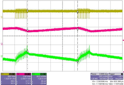
21 10.6 Active Burst 0.5W load Channel 1; C1 : Drain Source Voltage ( V DS ) Channel 2; C2 : Feedback voltage ( V FB ) Channel 3; C3 : Soft Start Voltage ( V SOFTS ) Channel 4; C4 : Output Voltage ( Vo ) Blanking time to enter burst mode : 21.9ms Figure 27 Active burst Vin=85Vac and 0.5W load Channel 1; C1 : Drain Source Voltage ( V DS ) Channel 2; C2 : Feedback voltage ( V FB ) Channel 3; C3 : Soft Start Voltage ( V SOFTS ) Channel 4; C4 : Output Voltage ( Vo ) Blanking time to enter burst mode : 21.6ms Figure 28 Active burst Vin=265Vac and 0.5W load Channel 1; C1 : Drain Source Voltage ( V DS ) Channel 2; C2 : Feedback voltage ( V FB ) Channel 4; C4 : Output Voltage ( Vo ) Output ripple : app. 60mV Figure 29 Output ripple at active burst Vin=85Vac and 0.5W load Channel 1; C1 : Drain Source Voltage ( V DS ) Channel 2; C2 : Feedback voltage ( V FB ) Channel 4; C4 : Output Voltage ( Vo ) Output ripple : app. 70mV Figure 30 Output ripple at active burst Vin=265Vac and 0.5W load Application Note


22 10.7 Frequency Jittering Channel 3; C3 : Soft Start Voltage ( V SOFTS ) Channel 3; C3 : Soft Start Voltage ( V SOFTS ) Frquency Jitter period : app. 3.02ms Frquency Jitter period : app. 2.97ms Figure 31 Frequency Jitter period shown in SOFTS Vin=85Vac and 12W load Figure 32 Frequency Jitter period shown in SOFTS Vin=265Vac and 12W load Channel 1; C1 : Drain Source Voltage ( V DS ) Channel 1; C1 : Drain Source Voltage ( V DS ) Frequency changing from 63.2kHz ~ 68.9KHz Frequency changing from 63.2kHz ~ 68.9KHz Figure 33 Frequency change shown at V Vin=85Vac and 12W load Figure 34 Frequency change shown at V Vin=265Vac and 12W load Application Note
23 10.8 Slope compensation This demo board is designed in Discontinuous Conduction Mode ( DCM ) operation. If the application is designed in Condtinous Condiction Mode ( CCM ) operation where the maximum duty cycle exceeds the 50% threshold, it needs to add the slope compensation network. Otherwise, the circuitry will be unstable. In this case, three more components ( 2 ceramic capacitors C17 / C18 and one resistor R19) is needed to add as shown in the circuit diagram below. Figure 33 Circuit Diagram Switch Mode Power Supply with Slope Compensation More information regarding how to calculate the additional components, see in the application note AN_SMPS_ICE2xXXX available on the internet: CoolSET F2. Application Note
24 References [1] Infineon Technologies, Datasheet CoolSET TM - F3 ( Jitter Version ) ICE3B0365J / ICE3B0565J OFF-Line SMPS Current Mode Controller with integrated 650V Startup Cell/Depl-CoolMOS [2] Infineon Technologies, Application Note AN-SMPS-ICE2xXXX-1 CoolSET TM ICE2xXXX for OFF-Line Switch Mode Power Supply (SMPS) [3] Infineon Technologies, Application Note AN-SMPS-ICE3DS01-1 CoolSET TM ICE3DS01 Current Mode Controller for OFF Line Switch Mode Power Supply (SMPS) [3] APEB Power Management Chapter September, Article 60W SMPS design achieving <100mW standby power Application Note
Application Note, V1.0, Nov 2004 ICE3B2565. SMPS Evaluation Board with CoolSET TM ICE3B2565. Power Management & Supply
 Application Note, V1.0, Nov 2004 ICE3B2565 SMPS Evaluation Board with CoolSET TM ICE3B2565 F3 Power Management & Supply N e v e r s t o p t h i n k i n g. Edition 2005-01-13 Published by Infineon Technologies
AN-EVALSF3-ICE3BS03LJG
 Application Note, V1.0, Nov 2007 AN-EVALSF3-ICE3BS03LJG 60W 16V SMPS Evaluation Board with F3 controller ICE3BS03LJG Power Management & Supply N e v e r s t o p t h i n k i n g. Edition 2007-11-14 Published
Power Management & Supply. Design Note. Version 2.3, August 2002 DN-EVALSF2-ICE2B765P-1. CoolSET 80W 24V Design Note for Adapter using ICE2B765P
 Version 2.3, August 2002 Design Note DN-EVALSF2-ICE2B765P-1 CoolSET 80W 24V Design Note for Adapter using ICE2B765P Author: Rainer Kling Published by Infineon Technologies AG http://www.infineon.com/coolset
Application Note, V1.2, Aug 2010 AN-EVAL3BR0665JF. 100W 18V SMPS Evaluation Board with CoolSET F3R ICE3BR0665JF. Power Management & Supply
 Application Note, V1.2, Aug 2010 AN-EVAL3BR0665JF 100W 18V SMPS Evaluation Board with CoolSET F3R ICE3BR0665JF Power Management & Supply N e v e r s t o p t h i n k i n g. Edition 2010-08-11 Published
Application Note AN- EVAL-2QR2280G-20W. 20W5V Evaluation Board with Quasi- Resonant CoolSET ICE2QR2280G. Power Management & Supply
 Application Note, V1.1, 23 May 2011 Application Note AN- EVAL-2QR2280G-20W 20W5V Evaluation Board with Quasi- Resonant CoolSET ICE2QR2280G Power Management & Supply N e v e r s t o p t h i n k i n g. Published
Power Management & Supply. Application Note. Version 3.0, Oct AN-EVALSF2-ICE2B765P2-3. CoolSET 80W 24V Evaluation Board using ICE2B765P2
 Version 3.0, Oct. 2003 Application Note AN-EVALSF2-ICE2B765P2-3 CoolSET 80W 24V Evaluation Board using ICE2B765P2 Author: Rainer Kling Published by Infineon Technologies AG http://www.infineon.com/coolset
Application Note, V1.0, Sep 2011 AN-EVAL3BR1465JF. 60W 18V SMPS Evaluation Board with CoolSET F3R ICE3BR1465JF. Power Management & Supply
 Application Note, V1.0, Sep 2011 AN-EVAL3BR1465JF 60W 18V SMPS Evaluation Board with CoolSET F3R ICE3BR1465JF Power Management & Supply N e v e r s t o p t h i n k i n g. Published by Infineon Technologies
CoolSET F3 Latch & Jitter Mode ICE3A1065LJ. 6 th Sept., Beijing. Infineon. Tim Hu. 7Apr06 Page 1. Page 1
 CoolSET F3 Latch & Jitter Mode ICE3A1065LJ Infineon 7Apr06 Page 1 Page 1 6 th Sept., 2006 - Beijing Infineon Integrated Power IC - CoolSET TM AC ~ V o DC IC T 2 CoolSET TM F3 Depl CoolMOS PWM IC 7Apr06
160W PFC Evaluation Board with DCM PFC controller TDA and CoolMOS
 Application Note Version 1.0 160W PFC Evaluation Board with DCM PFC controller TDA4863-2 and CoolMOS SPP08N50C3 Power Management & Supply TDA4863-2 SPP08N50C3 Ver1.0, _doc_release> N e v e
Application Note, V2.0, March 2006 EVALPFC2-ICE1PCS W PFC Evaluation Board with CCM PFC controller ICE1PCS01. Power Management & Supply
 Application Note, V2.0, March 2006 EVALPFC2-ICE1PCS01 300W PFC Evaluation Board with CCM PFC controller ICE1PCS01 Power Management & Supply N e v e r s t o p t h i n k i n g. Edition 2006-03-27 Published
2 8W 1 6 V E v a l u a t i o n B o a r d w i t h Q u a s i - R e s o n a n t C o o l S E T I C E 2 Q R G
 Application Note, V1.1, 1 March 2013 Application Note AN- EVAL-2QR0665G-28W 2 8W 1 6 V E v a l u a t i o n B o a r d w i t h Q u a s i - R e s o n a n t C o o l S E T I C E 2 Q R 0 6 6 5 G Power Management
Application Note, V1.1, October 2009 EVALPFC2-ICE2PCS W PFC Evaluation Board with CCM PFC controller ICE2PCS01. Power Management & Supply
 Application Note, V1.1, October 2009 EVALPFC2-ICE2PCS01 300W PFC Evaluation Board with CCM PFC controller ICE2PCS01 Power Management & Supply N e v e r s t o p t h i n k i n g. Edition 2009-10-13 Published
Application Note. EVALQS-190W-ICE2QS02G 190W Evaluation Board Based on Quasi-resonant Flyback Converter for LCD TV SMPS. Power Management & Supply
 Application Note, V1.1, 2 February 2009 Application Note EVALQS-190W-ICE2QS02G 190W Evaluation Board Based on Quasi-resonant Flyback Converter for LCD TV SMPS Power Management & Supply N e v e r s t o
N e v e r s t o p t h i n k i n g.
 Application Note, V., December 0 N e v e r s t o p t h i n k i n g. Edition 0--4 Published by Infineon Technologies Asia Pacific, 68 Kallang Way, 495 Singapore, Singapore Infineon Technologies AP 004.
Application Note, V1.0, Dec 2010 AN-EVAL3AR4780JZ. 12W 5V SMPS Evaluation Board with CoolSET F3R80 ICE3AR4780JZ. Power Management & Supply
 Application Note, V1.0, Dec 2010 AN-EVAL3AR4780JZ 12W 5V SMPS Evaluation Board with CoolSET F3R80 ICE3AR4780JZ Power Management & Supply N e v e r s t o p t h i n k i n g. Published by Infineon Technologies
Application Note, V1.0, Aug 2011 AN-EVAL3BR0680JZ. 30W 12V SMPS Evaluation Board with CoolSET F3R80 ICE3BR0680JZ. Power Management & Supply
 Application Note, V1.0, Aug 2011 AN-EVAL3BR0680JZ 30W 12V SMPS Evaluation Board with CoolSET F3R80 ICE3BR0680JZ Power Management & Supply N e v e r s t o p t h i n k i n g. Published by Infineon Technologies
EVALPFC-300W-ICE3PCS02/03G
 Application Note, V1.0, January 2011 EVALPFC-300W-ICE3PCS02/03G 300W PFC Evaluation Board with CCM PFC controller ICE3PCS02/03G Power Management & Supply N e v e r s t o p t h i n k i n g. Edition 2010-12-31
1 8W 5 V S m a l l S i z e L o w P r o f i l e E v a l u a t i o n B o a r d w i t h Q u a s i - R e s o n a n t C o o l S E T I C E 2 Q R G
 , V.0, 2 May 202 AN- EVAL-2QR765G-8W 8W 5 V S m a l l S i z e L o w P r o f i l e E v a l u a t i o n B o a r d w i t h Q u a s i - R e s o n a n t C o o l S E T I C E 2 Q R 7 6 5 G Power Management &
Application Note ANPS ICE2QS02G. Power Management & Supply. Converter Design Using Quasi-resonant PWM Controller ICE2QS02G
 Application Note, Version 1.0, 26 June 2008 Application Note ANPS0027 - ICE2QS02G Converter Design Using Quasi-resonant PWM Controller ICE2QS02G Power Management & Supply N e v e r s t o p t h i n k i
CoolSET TM Selection Guide
 CoolSET - New Type Numbering System Z Z CoolSET TM F2 Second generation off-line SMPS current mode controller with integrated CoolMOS power transistor as well as enhanced Protection Features and Lowest
Power Control ICs EVALLED-TDA4863G-40W. Application Note. Industrial & Multimarket
 Power Control ICs EVALLED-TDA4863G-40W Single Stage High Power Factor Flyback Converter for Offline LED Supply TDA4863G TLE4305G Application Note Revision.0, 00-04-0 Industrial & Multimarket Edition 00-04-0
D e m o B o a r d U s e r s M a n u a l. Demoboard Rev.1.0, Standard Power
 IFX80471SKV D e m o B o a r d U s e r s M a n u a l Demoboard Rev.1.0, 2012-05-15 Standard Power 1 Abstract Note: The following information is given as a guideline for the implementation of the device
Infineon LLC IC solution & QR Coolset. Willion Chen ASIC & IC System Application Engineer
 Infineon LLC IC solution & QR Coolset Willion Chen ASIC & IC System Application Engineer Infineon LLC Solution for LED TV LLC stage ICE2HS01G Timer EnA OCP LOAD FREQ TD Delay Vref Vmc Vres ICE2HS01G PG-DSO-20
12V-65W WIDE-RANGE INPUT MAINS ADAPTER USING THE L6566B
 APPLICATION NOTE 12V-65W WIDE-RANGE INPUT MAINS ADAPTER USING THE L6566B Introduction This note describes the characteristics and the features of a 65 W reference board, wide-range input mains, AC-DC adapter
22 W 12 V 5 V SMPS demo board with ICE5GR2280AG
 ER_201707_PL83_015 22 W 12 V 5 V SMPS demo board with ICE5GR2280AG About this document Scope and purpose This document is an engineering report that describes a universal-input 22 W 12 V 5 V off-line isolated
5V/550mA Battery Charger Solution Using AP3703
 System Engineering Department BCD Semiconductor Manufacturing Limited 01/19/2009 Summary of Report Specifications 85~264Vac, 5V/550mA Applications Key features Cellphone charger or adapter Primary Side
SHENZHEN DONGKE SEMICONDUCTOR CO., LTD SPECIFICATION
 SPECIFICATION 1. DESCRIPTION The DK124 IC is specially design for off-line switch mode power supply, maximum power is 24W. Different from PWM controller and external power separated MOS combination design,
ILD2035. MR16 3 W Control Board with ILD2035. Application Note AN214. Industrial and Multimarket. Revision: 1.0 Date:
 ILD2035 MR16 3 W Control Board with ILD2035 Application Note AN214 Revision: 1.0 Date: Industrial and Multimarket Edition Published by Infineon Technologies AG 81726 Munich, Germany 2011 Infineon Technologies
AN2001 Application note
 Application note VIPower : the VIPer53-E single output reference board with 90 to 264 Vac input, 24 W output Introduction The VIPer53-E combines an enhanced current mode PWM controller with a high voltage
AN2000 Application note
 Application note VIPower: VIPer53A dual output reference board 90 to 264 VAC input, 24W output Introduction This is an off-line wide range VIPer53 dual output reference board that is set up for secondary
Application Note, V1.1, Apr CoolMOS TM. AN-CoolMOS-08 SMPS Topologies Overview. Power Management & Supply. Never stop thinking.
 Application Note, V1.1, Apr. 2002 CoolMOS TM AN-CoolMOS-08 Power Management & Supply Never stop thinking. Revision History: 2002-04 V1.1 Previous Version: V1.0 Page Subjects (major changes since last revision)
15 W HVDCP Quick Charge 3.0 Compatible CV/CC Charger
 Design Note 15 W HVDCP Quick Charge 3.0 Compatible CV/CC Charger Device Application Input Voltage NCP4371AAC NCP1361EABAY NCP4305D Quick Charge 3.0, Cell Phone, Laptop Charger Output Voltage Output Ripple
FEBFSL336LRN_CS04U07A Evaluation Board. Fairchild Multi-Output Buck Converter. Featured Fairchild Product: FSL336LRN
 User Guide for FEBFSL336LRN_CS04U07A Evaluation Board Fairchild Multi-Output Buck Converter Featured Fairchild Product: FSL336LRN Direct questions or comments about this evaluation board to: Worldwide
UNISONIC TECHNOLOGIES CO., LTD UC1103 Preliminary CMOS IC
 UNISONIC TECHNOLOGIES CO., LTD HIGH PRECISION CC/CV PRIMARY SIDE SWITCHING REGULATOR DESCRIPTION The UTC UC1103 is a primary control unit for switch mode charger and adapter applications. The controlled
LD /15/2011. Green-Mode PWM Controller with Frequency Swapping and Integrated Protections. Features. General Description.
 12/15/2011 Green-Mode PWM Controller with Frequency Swapping and Integrated Protections Rev. 02a General Description The LD7536 is built-in with several functions, protection and EMI-improved solution
High Efficiency DC-DC Converter Module
 Design Note DN05108/D High Efficiency DC-DC Converter Module Device Application Input Voltage Output Power Topology I/O Isolation NCP12700 Module 9 to 36 Vdc Up to 15 W Output Specification Output Voltage
AN1513 Application note
 Application note VIPower: 30 W SMPS using VIPer50A-E Introduction In a growing consumer market, cost effective solutions with good performances and reliability able to meet energy saving international
Reference Design Report for a 21W (42V/0.5A) LED Driver Using SFL900
 LED Driver Using SFL900") Reference Design Report for a 21W (42V/0.5A) LED Driver Using SFL900 Specification Application 90-264VAC Input; 42V/0.5A output LED Driver Author Document Number System Engineering Department SFL900_LED
Reference Design Report for a 21W (42V/0.5A) LED Driver Using SFL900 Specification Application 90-264VAC Input; 42V/0.5A output LED Driver Author Document Number System Engineering Department SFL900_LED
EVALPFC-300W-IPP60R190P6
 EVALPFC-300W-IPP60R190P6 3 0 0 W P F C E v a l u a t i o n B o a r d I P P 6 0 R 1 9 0 P 6 w i t h C C M P F C c o n t r o l l e r IFAT PMM APS SE SL Steiner Alois Stückler Franz Zechner Florian (IFAT
14 W 15 V 5 V SMPS demo board with ICE5AR4780BZS
 ER_201709_PL83_017 14 W 15 V 5 V SMPS demo board with ICE5AR4780BZS About this document Scope and purpose This document is an engineering report that describes universal-input 14 W 15 V and 5 V off-line
AN2103 APPLICATION NOTE VIPower: VIPer12A ISOLATED FLYBACK CONVERTER REFERENCE BOARD
 AN203 APPLICATION NOTE VIPower: VIPer2A ISOLATED FLYBACK CONVERTER REFERENCE BOARD. ABSTRACT The presented circuit can be used to produce multiple isolated voltage outputs. It is dedicated to building
MP2313 High Efficiency 1A, 24V, 2MHz Synchronous Step Down Converter
 The Future of Analog IC Technology MP2313 High Efficiency 1A, 24V, 2MHz Synchronous Step Down Converter DESCRIPTION The MP2313 is a high frequency synchronous rectified step-down switch mode converter
UNISONIC TECHNOLOGIES CO., LTD UC1108 Preliminary CMOS IC
 UNISONIC TECHNOLOGIES CO., LTD LOW-POWER OFF-LINE PRIMARY SIDE REGULATION CONTROLLER DESCRIPTION The UTC UC1108 is a primary control unit for switch mode charger and adapter applications. The controlled
DESCRIPTION FEATURES APPLICATIONS TYPICAL APPLICATION. 500KHz, 18V, 2A Synchronous Step-Down Converter
 DESCRIPTION The is a fully integrated, high-efficiency 2A synchronous rectified step-down converter. The operates at high efficiency over a wide output current load range. This device offers two operation
Application Note, Rev.1.0, November 2010 TLE8366. The Demoboard. Automotive Power
 Application Note, Rev.1.0, November 2010 TLE8366 Automotive Power Table of Contents 1 Abstract...3 2 Introduction...3 3 The Demo board...4 3.1 Quick start...4 3.2 The Schematic...5 3.3 Bill of Material...6
MP2314 High Efficiency 2A, 24V, 500kHz Synchronous Step Down Converter
 The Future of Analog IC Technology MP2314 High Efficiency 2A, 24V, 500kHz Synchronous Step Down Converter DESCRIPTION The MP2314 is a high frequency synchronous rectified step-down switch mode converter
Fairchild Reference Design
 Fairchild Reference Design www.fairchildsemi.com This reference design supports inclusion of the FSL306LRN. It should be used in conjunction with the FSL306LRN datasheet as well as Fairchild s application
AC-DC SMPS: Up to 15W Application Solutions
 AC-DC SMPS: Up to 15W Application Solutions Yehui Han Applications Engineer April 2017 Agenda 2 Introduction Flyback Topology Optimization Buck Topology Optimization Layout and EMI Optimization edesignsuite
AN-9719 Applying Fairchild Power Switch (FPS ) FSL1x7 to Low- Power Supplies
 FSL1x7 to Low- Power Supplies") www.fairchildsemi.com Applying Fairchild Power Switch (FPS ) FSL1x7 to Low- Power Supplies 1. Introduction The highly integrated FSL-series consists of an integrated current-mode Pulse Width Modulator
www.fairchildsemi.com Applying Fairchild Power Switch (FPS ) FSL1x7 to Low- Power Supplies 1. Introduction The highly integrated FSL-series consists of an integrated current-mode Pulse Width Modulator
MIC2196. Features. General Description. Applications. Typical Application. 400kHz SO-8 Boost Control IC
 400kHz SO-8 Boost Control IC General Description Micrel s is a high efficiency PWM boost control IC housed in a SO-8 package. The is optimized for low input voltage applications. With its wide input voltage
Designing Offline HB LED Current Sources with Primary Side Control Using E-series Fairchild Power Switch (FPS)
") Designing Offline HB LED Current Sources with Primary Side Control Using E-series Fairchild Power Switch (FPS) Carl Walding Global Power Resource Center, Hoffman Estates, IL www.fairchildsemi.com Overview
Designing Offline HB LED Current Sources with Primary Side Control Using E-series Fairchild Power Switch (FPS) Carl Walding Global Power Resource Center, Hoffman Estates, IL www.fairchildsemi.com Overview
AN4583 Application note
 AN4583 Application note Cable set-top box SMPS adaptor using VIPER27 Introduction Harjeet Singh, Alessandro Cannone Abstract: a set-top box (STB) is a cable box, placed in the consumer's house, that has
High Efficiency DC-DC Converter Module
 Design Note DN05109/D High Efficiency DC-DC Converter Module Device Application Input Voltage Output Power Topology I/O Isolation NCP12700 Module 18 to 160 Vdc Up to 15 W DCM Flyback Isolated Output Specification
FL103 Primary-Side-Regulation PWM Controller for LED Illumination
 FL103 Primary-Side-Regulation PWM Controller for LED Illumination Features Low Standby Power: < 30mW High-Voltage Startup Few External Component Counts Constant-Voltage (CV) and Constant-Current (CC) Control
Step down - LED controller IC for external power stages ILD4001
 Target Datasheet, Rev. 1.0, July 2009 Step down - LED controller IC for external power stages ILD4001 Small Signal Discretes Edition 2009-07-06 Published by Infineon Technologies AG, 81726 München, Germany
Wide range isolated flyback demonstration board, single output 12 V/4.2 W based on the VIPER16LN. Description
 Wide range isolated flyback demonstration board, single output 12 V/4.2 W based on the VIPER16LN Data brief Features GIPD1712121716FSR Universal input mains range: input voltage 90-264 V AC frequency 45-65
AN TEA1836XT GreenChip SMPS control IC. Document information
 Rev. 1 18 April 2014 Application note Document information Info Keywords Abstract Content TEA1836XT, DCM flyback converter, high efficiency, burst mode operation, low audible noise, high peak power, active
Driving 2W LEDs with ILD4120
 Application Note AN270 Revision: 0.4 Date: LED Driver & AF Discretes Edition 2011-09-13 Published by Infineon Technologies AG 81726 Munich, Germany 2011 Infineon Technologies AG All Rights Reserved. LEGAL
UNISONIC TECHNOLOGIES CO., LTD UC3846 LINEAR INTEGRATED CIRCUIT
 UNISONIC TECHNOLOGIES CO., LTD UC3846 LOW COST POWER-SAVING MODE PWM CONTROLLER FOR FLYBACK CONVERTERS DESCRIPTION The UTC UC3846 is a high performance current mode PWM controller ideally suited for low
CURRENT MODE PWM+PFM CONTROLLER WITH BUILT-IN HIGH VOLTAGE MOSFET
 CURRENT MODE PWM+PFM CONTROLLER WITH BUILT-IN HIGH VOLTAGE MOSFET DESCRIPTION SD6832 is current mode PWM+PFM controller with built-in highvoltage MOSFET used for SMPS It features low standby power and
AT V,3A Synchronous Buck Converter
 FEATURES DESCRIPTION Wide 8V to 40V Operating Input Range Integrated 140mΩ Power MOSFET Switches Output Adjustable from 1V to 25V Up to 93% Efficiency Internal Soft-Start Stable with Low ESR Ceramic Output
AN1736 Application note VIPower: VIPer22A dual output reference board 90 to 264 VAC input, 10W output Introduction
 Application note VIPower: VIPer22A dual output reference board 90 to 264 VAC input, 10W output Introduction This is an off-line wide range VIPer22A dual outputs power supply at a switching frequency of
Current Mode PWM Power Switch. Code A B G H I J Year Code A B C Month Jan. Feb. Mar. Apr.
 Current Mode PWM Power Switch Preliminary GR8935 Features Current mode PWM ery low startup current Under-voltage lockout ULO Non-audible-noise green-mode control Fixed switching frequency of 50KHz Cycle-by-cycle
ACE726C. 500KHz, 18V, 2A Synchronous Step-Down Converter. Description. Features. Application
 Description The is a fully integrated, high-efficiency 2A synchronous rectified step-down converter. The operates at high efficiency over a wide output current load range. This device offers two operation
SMPS IC SmartRectifier IR1161LPBF
 SMPS IC SmartRectifier IR1161LPBF SmartRectifier Control IC Features Secondary side synchronous rectification controller DCM, CrCM Flyback and resonant half-bridge topologies Direct sensing of MOSFET drain
Positive to Negative Buck-Boost Converter Using LM267X SIMPLE SWITCHER Regulators
 Positive to Negative Buck-Boost Converter Using LM267X SIMPLE SWITCHER Regulators Abstract The 3rd generation Simple Switcher LM267X series of regulators are monolithic integrated circuits with an internal
AN APPLICATION NOTE
 AN1539 - APPLICATION NOTE VIPower: LOW COST UNIVERSAL INPUT SMPS FOR DIGITAL SET-TOP BOX BASED ON VIPer50 F. Gennaro ABSTRACT In this paper the design of a low cost power supply for digital Set Top Box
AN1258 Application note
 AN58 Application note VIPer0-E standby application demonstration board Introduction This general flyback circuit can be used to produce any output voltage in primary or secondary mode regulation and is
UNISONIC TECHNOLOGIES CO., LTD UCSR3651S Preliminary CMOS IC
 UNISONIC TECHNOLOGIES CO., LTD UCSR3651S Preliminary CMOS IC HIGH PRECISION CC/CV PRIMARY-SIDE PWM POWER SWITCH DESCRIPTION The UTC UCSR3651S is a primary control switch mode charger and adapter applications.
Single Channel Linear Controller
 Single Channel Linear Controller Description The is a low dropout linear voltage regulator controller with IC supply power (VCC) under voltage lockout protection, external power N-MOSFET drain voltage
FAN6862R / FAN6862L Highly Integrated Green-Mode PWM Controller
 FAN6862R / FAN6862L Highly Integrated Green-Mode PWM Controller Features Low Startup Current: 8µA Low Operating Current in Green Mode: 3mA Peak-Current-Mode Operation with Cycle-by-Cycle Current Limiting
DESCRIPTION FEATURES PROTECTION FEATURES APPLICATIONS. RS2320 High Accurate Non-Isolated Buck LED Driver
 High Accurate Non-Isolated Buck LED Driver DESCRIPTION RS2320 is especially designed for non-isolated LED driver. The building in perfect current compensation function ensures the accurate output current.
STEVAL-ISA110V1. 12 V/12 W wide-range non-isolated flyback based on the VIPER26LN. Features. Description
 12 V/12 W wide-range non-isolated flyback based on the VIPER26LN Data brief Features Universal input mains range: input voltage 90-264 V AC frequency 45-65 Hz Single output voltage: 12 V @ 1 A continuous
ANP012. Contents. Application Note AP2004 Buck Controller
 Contents 1. AP004 Specifications 1.1 Features 1. General Description 1. Pin Assignments 1.4 Pin Descriptions 1.5 Block Diagram 1.6 Absolute Maximum Ratings. Hardware.1 Introduction. Typical Application.
Green-Mode PWM Controller with Integrated Protections
 Green-Mode PWM Controller with Integrated Protections Features High-voltage (500) startup circuit Current mode PWM ery low startup current (
CR6842. Green-Power PWM Controller with Freq. Jittering. Features. Applications. General Description. Leading-edge blanking on Sense input
 Green-Power PWM Controller with Freq. Jittering Features Low Cost, Green-Power Burst-Mode PWM Very Low Start-up Current ( about 7.5µA) Low Operating Current ( about 3.0mA) Current Mode Operation Under
TFT-LCD DC/DC Converter with Integrated Backlight LED Driver
 TFT-LCD DC/DC Converter with Integrated Backlight LED Driver Description The is a step-up current mode PWM DC/DC converter (Ch-1) built in an internal 1.6A, 0.25Ω power N-channel MOSFET and integrated
High Accurate non-isolated Buck LED Driver
 High Accurate non-isolated Buck LED Driver Features High efficiency (More than 90%) High precision output current regulation (-3%~+3%) when universal AC input voltage (85VAC~265VAC) Lowest cost and very
Voltage-Current Regulator TLE 4305
 Voltage-Current Regulator TLE 4305 Features Wide supply voltage operation range Wide ambient temperature operation range Minimized external circuitry High voltage regulation accuracy High current limit
Power Charge Pump and Low Drop Voltage Regulator TLE 4307
 Power Charge Pump and Low Drop Voltage Regulator TLE 4307 Power Charge Pump Circuit Features High Current Capability Short Circuit Protection Overtemperature Protection Active Zener Circuit Very Low Drop
TLE4916-1K. Datasheet. Sense & Control. Low Power Automotive Hall Switch. Rev.1.0,
 Low Power Automotive Hall Switch Datasheet Rev.1.0, 2010-02-23 Sense & Control This datasheet has been downloaded from http://www.digchip.com at this page Edition 2010-02-23 Published by Infineon Technologies
Smart Multichannel Switches
 Application Note, V1.2, August 2005 Smart Multichannel Switches Technical considerations for parallel channel operation applications Automotive Power by Bernard Wang Never stop thinking. Edition 2005-08
Green-Mode PWM Controller with Integrated Protections
 Green-Mode PWM Controller with Integrated Protections Features High-voltage (500) startup circuit Current mode PWM ery low startup current (
Universal AC input, Primary Side Regulation AP3983E 12V-1.5A EV1 Board User Guide
 Universal AC input, Primary Side Regulation General Description Based on Flyback topology, the Primary side Regulated AP3983E EV1 board is designed to serve as an example for High Efficiency, low cost
Green-Mode PWM Controller with Hiccup Protection
 Green-Mode PWM Controller with Hiccup Protection Features Current Mode Control Standby Power below 100mW Under-Voltage Lockout (UVLO) Non-Audible-Noise Green-Mode Control 65KHz Switching Frequency Internal
MP2225 High-Efficiency, 5A, 18V, 500kHz Synchronous, Step-Down Converter
 The Future of Analog IC Technology DESCRIPTION The MP2225 is a high-frequency, synchronous, rectified, step-down, switch-mode converter with built-in power MOSFETs. It offers a very compact solution to
ACT111A. 4.8V to 30V Input, 1.5A LED Driver with Dimming Control GENERAL DESCRIPTION FEATURES APPLICATIONS TYPICAL APPLICATION CIRCUIT
 4.8V to 30V Input, 1.5A LED Driver with Dimming Control FEATURES Up to 92% Efficiency Wide 4.8V to 30V Input Voltage Range 100mV Low Feedback Voltage 1.5A High Output Capacity PWM Dimming 10kHz Maximum
Designing A Medium-Power Resonant LLC Converter Using The NCP1395
 Designing A Medium-Power Resonant LLC Converter Using The NCP395 Prepared by: Roman Stuler This document describes the design procedure needed to implement a medium-power LLC resonant AC/DC converter using
SG6846 APPLICATIONS DESCRIPTION. Preliminary Specification. Highly-Integrated Green-Mode PWM Controller
 FEATURES Linearly decreasing PWM frequency at light load Burst-mode at light load and zero load Low start-up current (20uA) Low operating current (4mA) Leading-edge blanking Built-in synchronized slope
HF V Offline Switching Regulator
 HF900 900V Offline Switching Regulator The Future of Analog IC Technology DESCRIPTION The HF900 is a flyback regulator with an integrated 900V MOSFET. Requiring a minimum number of external components,
Green-Mode PWM Controller with Hiccup Protection
 Green-Mode PWM Controller with Hiccup Protection Features Current Mode Control Standby Power below 100mW Under-Voltage Lockout (UVLO) Non-Audible-Noise Green-Mode Control 65KHz Switching Frequency Internal
Low Drop Voltage Regulator TLE
 Low Drop Voltage Regulator TLE 4266-2 Features Fixed output voltage 5. V or 3.3 V Output voltage tolerance ±2%, ±3% 15 ma current capability Very low current consumption Low-drop voltage Overtemperature
SR A, 30V, 420KHz Step-Down Converter DESCRIPTION FEATURES APPLICATIONS TYPICAL APPLICATION
 SR2026 5A, 30V, 420KHz Step-Down Converter DESCRIPTION The SR2026 is a monolithic step-down switch mode converter with a built in internal power MOSFET. It achieves 5A continuous output current over a
LD7536R 05/11/2010. Green-Mode PWM Controller with Frequency Swapping and Integrated Protections. General Description. Features.
 05/11/2010 Green-Mode PWM Controller with Frequency Swapping and Integrated Protections Rev. 00 General Description The LD7536R is built-in with several functions, protection and EMI-improved solution
NOT RECOMMENDED FOR NEW DESIGNS REFER TO MP2147 MP Ultra Low Voltage, 4A, 5.5V Synchronous Step-Down Switching Regulator DESCRIPTION FEATURES
 The Future of Analog IC Technology DESCRIPTION The MP38115 is an internally compensated 1.5MHz fixed frequency PWM synchronous step-down regulator. MP38115 operates from a 1.1V to 5.5V input and generates
LD7536E 5/28/2012. Green-Mode PWM Controller with Frequency Swapping and Integrated Protections. General Description. Features.
 5/28/2012 Green-Mode PWM Controller with Frequency Swapping and Integrated Protections Rev. 00 General Description The is built-in with several functions, protection and EMI-improved solution in a tiny
SG5841/J FEATURES APPLICATIONS DESCRIPTION TYPICAL APPLICATION. Product Specification. Highly-Integrated Green-Mode PWM Controller
 FEATURES Green-mode PWM Controller Low Start-Up Current (4uA) Low Operating Current (4mA) Programmable PWM frequency with Hopping Peak-current-mode Control Cycle-by-Cycle Current Limiting Synchronized
AN1489 Application note
 Application note VIPower: non isolated power supply using VIPer20 with secondary regulation Introduction Output voltage regulation with adjustable feedback compensation loop is very simple when a VIPer
FAN6747WALMY Highly Integrated Green-Mode PWM Controller
 FAN6747WALMY Highly Integrated Green-Mode PWM Controller Features High-Voltage Startup AC-Line Brownout Protection by HV Pin Constant Output Power Limit by HV Pin (Full AC-Line Range) Built-in 8ms Soft-Start
LM5034 High Voltage Dual Interleaved Current Mode Controller with Active Clamp
 High Voltage Dual Interleaved Current Mode Controller with Active Clamp General Description The dual current mode PWM controller contains all the features needed to control either two independent forward/active