Converting the Motorola 42 to 50 MHz MT1000 or P200 to 50 to 54 MHz
|
|
|
- Clare Marilyn Stone
- 5 years ago
- Views:
Transcription
1 Converting the Motorola 42 to 50 MHz MT1000 or P200 to 50 to 54 MHz Hardware mods by WB8VLC. RSS mods by WA1MIK Transmitter and receiver mods to tune the entire band and direct RSS frequency entry. Revision 6: 31-Mar-2012 This revised document now has WA1MIK s RSS modifications to allow direct frequency entry from RSS. Hex-editing of the code plug is no longer necessary. Go to this web page and download these documents. index.html Document 1: Radius P200 Low-band RF board information <Schematic Document 2: Radius P200 Low-band Alignment Procedure <Service manual Document 3. Modifying the low-band P200/MT1000 RSS to cover the 6- meter and 10-meter bands VCO CAPACITORS: Digi-Key 0805 chip caps QTY: Reference designator value description 1 C1 VCO 7.5 pf Digi-Key ND 1 C2 VCO 18 pf Digi-Key ND RF BOARD CAPACITORS. Digi-Key 0805 chip capacitors QTY: Reference designator value description 1 C2 100pF Digi-Key ND 1 C8 68pF Digi-Key ND 1 C pF Digi-Key ND 1 C117 75pF Digi-Key ND 4 C124, C125, C130, C pF Digi-Key ND 1 C126 20pF Digi-Key ND 1 C127 39pF Digi-Key ND NOTE: RF BOARD C2 is not the same as VCO C2. RF BOARD RESISTORS. Digi-Key 0805 chip resistors QTY: reference designator value description 2 R108, R ohm Digi-Key P20ACT-ND 1 R ohm Digi-Key P33ACT-ND 1 R ohm Digi-Key P220ACT-ND
2 Note: data taken after several conversions shows that C1 optimum is 7.5 pf and C2 optimum is ~17.5 pf, (18pF is fine) but you can go as low as 6.8 pf on C1 and 15 pf on C2 and as high as 9 pf for C1 and 20pF for C2 and coverage of the entire ham band is still possible. WHAT RSS should you be using? For all MT1000 low band models with the LCD display: If you have the MT1000 low band radio with the 2-digit LCD display, these models typically came as 32 or 99 channel radios and from some information that others have sent me they may all be capable of 99 channels. The correct RSS for all low band LCD display models is regular MT1000.EXE; do not use the P200LB.EXE for any of the low band LCD display model MT1000s. For all P200 and MT1000, 6 channel models only: Use the P200LB.EXE only if your radio is the 6-channel P200 or 6-channel MT1000 low band model. NOTE: If the radio you have is not in the 42 to 50 split then stop right now as the modifications to take a 36 to 42 split to either 6 meters or 10 meters are more in depth and still being documented or worked on at this time. However; I have successfully moved a 36 to 42 MHz split MT1000 to the 10-meter ham band with great results but this is still being documented as the receiver pre-selector changes are numerous.

3 Radio disassembly 1. Open the radio up by removing the 2 back cover screws and remove the 2 bottom screws holding the front cover on. Loosen the 2 screws holding the battery plate on; these are the larger screws near the center of the bottom plate. The other 2 screws are smaller and hold the front cover on. Don t remove the 3 screws holding the battery contacts. See Figure 1.0 Figure Pull the front cover away from the back section and disconnect the speaker flex cable. 3. Pull the radio away from and out of the LEXAN case by grasping the antenna and pulling away from the Lexan case.

4 4. To remove the controller module (this is the large metal module in the center of the radio) first remove the 4 side screws. Remove the plastic assembly covering the transmitter trimmer capacitor. See figure 2 Figure 2. Remove 4 screws from controller. Remove the plastic cover assembly near the top of the radio.

5 5. Next gently lift the controller module away from the main RF board/radio casing by pulling the 2 top connectors off. Lift the board up at ~ 45 degree angle from the top and remove the back side connector. See Figure 3. Figure 3. Controller removal from radio
6 6. Carefully pull the controller up and slightly away from the main RF board. Using a pair of tweezers or small blade screw driver push the 2 bottom connectors that connect to the VCO up and away to free the controller board from the main board. See figure 4. Figure 4. Controller to VCO connector removal 7. Place the controller module aside.

7 8. Turn the radio over so the back metal shield/cover is facing up and remove the 4 screws securing the shield to the module. See figure 5. Figure 5. Remove the 4 screws holding the RF back shield

8 9. Look towards the bottom with the back shield removed and there are 2 screws securing the VCO module, they are the only 2 screws near the bottom of the radio module. Remove these screws. See figure 6.0 Figure 6. VCO hold down screws

9 Desoldering the VCO module from the main RF board 10. Using a solder sucker or some de-soldering wick remove the solder from the 11 pins shown in figure 7 and pull the VCO module away from the radios Main Printed circuit board. Figure 7. Unsoldering the VCO from main RF board Once the VCO is removed from the main RF board, pull the snap on piece of the 3 piece VCO cover off of the VCO synthesizer assembly as follows. See figures 8A thru 8E.

10 Refer to figures 8A thru 8E, Remove the 2 VCO covers and set aside. Unsolder the 10 pins from the controller part of the VCO module so that the RF section of the VCO module can be separated from the VCO controller. Pull the VCO RF section of the VCO board up and away from the remaining metal cover. The result should be the RF VCO section in figure 8E. Figure 8A. Remove the thinner clip on VCO cover by unclipping and lifting the left side then lift the right side away and set this cover aside.

11 Figure 8B. Remove the thicker VCO back cover by pulling/lifting away from the VCO assembly and set it aside.

12 Figure 8C. Unsolder 10 pins to free the VCO RF assembly from the VCO controller board.

13 Figure 8D. Pull the VCO controller board out and pull the VCO RF board up to free each board from the metal VCO housing assembly.

14 Figure 8E. VCO RF board removed from VCO controller board NOTE: Take your time here and be patient with these pins during this step. Use a small tip hot solder iron and lots of solder wick or better yet if you can get your hands on an automatic solder sucker this works excellent for separating the 2 VCO boards. You do not want to pull a via hole off of the circuit board connector so take your time at this step. Use an EYE-LOOP to inspect each of the above 13 pins to make sure that all solder is removed before separating the metal shield that holds the 2 VCO board assemblies together.
15 Refer to figure 9. Remove the capacitor at the location labeled C1 in figure 4 and replace it with a 0805 size 7.5pF chip capacitor. Figure 9. C1 location. Remove and replace the original capacitor with a 7.5pF chip capacitor.

16 11. Refer to figure 10. Remove the capacitor at the location labeled C2 and replace it with a 0805 size 18 pf chip capacitor. Figure 10. C2 location. Replace with an 18pF chip capacitor. 12. Re-assemble the VCO in reverse order and solder it back in to the main RF board. Screw the 2 VCO module hold down screws back in to the main RF board to secure the VCO/synthesizer module.

17 Modifying the Transmitter and Receiver for full coverage 13. Place the radio on its front and remove the single top screw holding the RF board to the radios case. See figure 11. Figure 11. Remove the screw near the top center of the radio
18 14. Turn the radio over and unsolder the red lead from the power on/off switch. See figure 12. Figure 12. Unsolder the red lead connected to the Power on/off switch
19 15. Turn the radio over so the back side of the RF board is facing up. 16. Unsolder the center pin of the RF connector, the Ground tab holding the top frame and the 2 U-clips holding the pins coming from the radios top multi pin connector. See figure 13. Figure 13. The 4 connections that are unsoldered to free the RF board from the radio case/top connector assembly.
20 17. Gently lift the Main RF board away from the top radio case by pulling from the top of the RF board. You may have to gently pry the top case away from the RF board to dislodge the top 2 connector pins away from the U-clips. See figure 14 below. Figure 14. RF board U clips pulled away from top connector pins 18. When the RF board U clips are free from the Top UDC connectors pins lift the main RF board away from the radio case and set the radio case aside
21 19. See figure 15. With the RF board facing up, as in figure 14 below, locate inductor L120 nearest the antenna. Note its location for the next step where the board is flipped over. Figure 15. Component side location of inductor L120

22 20. Flip the RF board over and unsolder inductor L120 at the 2 pins shown in figure 16 below. Figure 16. Inductor L120, unsolder these 2 leads to remove.

23 21. Flip the RF board over and using a pair of tweezers, remove Inductor L120 from the main RF board. 22. Remove 2 turns from inductor L120 and form this new inductor so the leads come off in the same direction as the original part. This new modified inductor will now have 8 turns. 23. Re-install modified inductor L120 back in its original position and solder it to the RF board. See figure 17. Do not let the leads protrude more than about 5 mils on the back side of the RF board, the leads should only stick out just enough to solder to the original VIA holes. Figure 17. Modified inductor L120 re-installed in board.
24 24. See figure 18. To gain access to Inductor L119 you must first unsolder and pull off the shield covering L119 from the back side of the RF board. Figure 18. Remove the shield covering L119 on the top side of the RF board.
25 25. See figure 19. Unsolder the 2 pins holding L119 s shield to the RF board. Figure 19. Unsolder these pins to remove L119 s shield. 26. Remove the shield covering L119 and set it aside.
26 27. See figure 20, Unsolder the 2 pins to remove inductor L119 from the RF board. Figure 20. Unsolder these 2 pins to remove inductor L Pull L119 off of the RF board and remove 1 turn from it. This modified part will now have 7 turns. 29. Re-install modified L119 back in the RF board and solder the leads back in. Do not let the leads protrude more than about 5 mils on the back side of the RF board, the leads should only stick out just enough to solder to the original VIA holes. 30. Re-install the shield over modified L119 and solder it to the RF board.

27 31. See figure 21. Locate the position of inductor L124. Figure 21. Component side location of inductor L124
28 32. See figure 22. Unsolder L124 s pins from the backside of the RF board. Figure 22. Unsolder these 2 pins to remove inductor L Pull L124 off of the RF board and remove 1 turn, tin the leads just like was done with L120 and L119 and re-install and solder this new part back into the RF board.
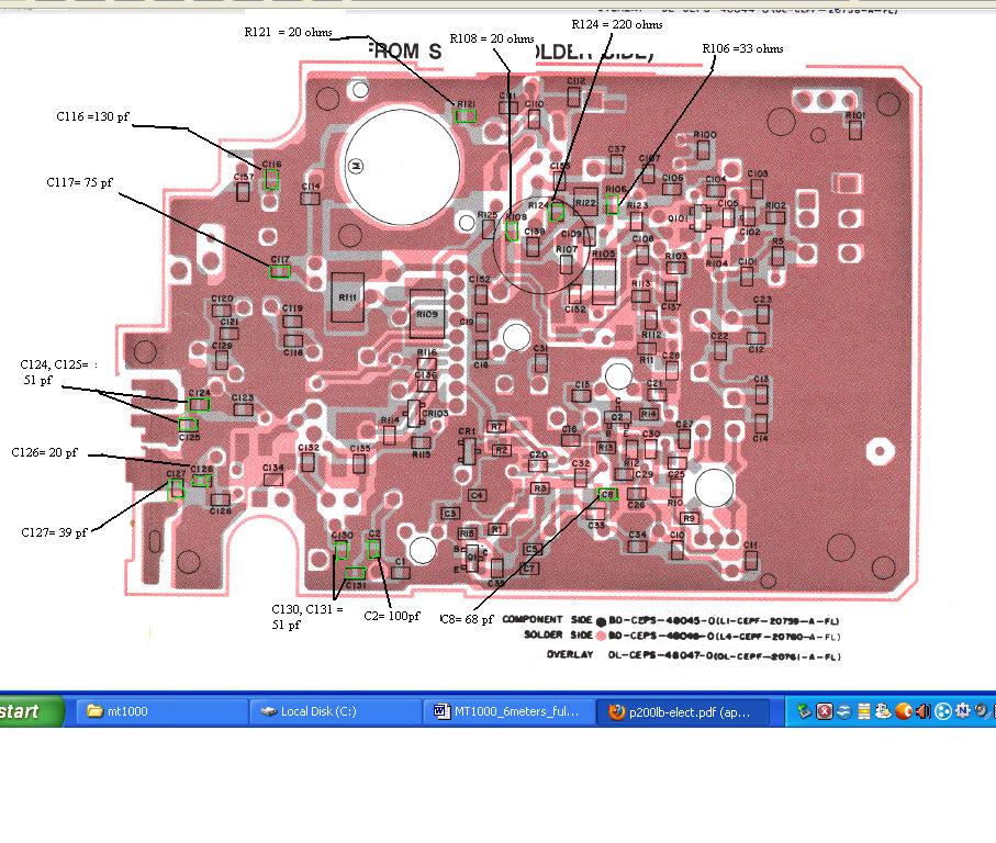
29 RF BOARD PARTS CHANGES, SEE COMPONENT LOCATOR ON NEXT PAGE. RECEIVER /ANTENNA SWITCH CAPACITOR CHANGES Download this document, #68P81085E58 for all of the following capacitor and resistor component locations on the main RF board. These component numbers are the schematic ref designators from the above condensed manual, which applies to the P200LB or MT1000LB radios. See page 5 of this condensed manual for the following parts locations. 1. Locate capacitor C8 and replace it with a 68 pf chip cap. 2. Locate capacitor C2 and replace it with a 100 pf chip. 3. Locate capacitors C131 and C130 and replace each with a 51 pf chip cap. 4. Locate capacitor C126 and replace it with a 20 pf chip cap. 5. Locate capacitor C127 and replace with a 39 pf chip cap. TRANSMITTER CAPACITOR AND RESISTOR CHANGES. Again see page 5 of document #68P81085E58, for component locations. These component designators are the schematic ref designators from the condensed manual above this applies to the P200LB or MT1000LB radios. See page 5 of this condensed manual for the following parts locations. TRANSMITTER POWER AMP CAPACITOR CHANGES 1. Locate Capacitors C125 and C124 and replace each with a 51 pf chip cap. 2. Locate C117 and replace with a 75 pf chip cap. 3. Locate C116 and replace with a 130 pf chip cap. TRANSMITTER RESISTOR CHANGES FOR STABILITY 1. Locate R108 and R121 and replace each with a 20 ohm chip resistor. 2. Locate R106 and replace with a 33 ohm chip resistor. 3. Locate R124 and replace with a 220 ohm chip resistor.
30

31 34. Re-install the RF board back in the radio casing by placing the VCO end in first then press the U-clips down so they make contact with the 2 top connector pins. NOTE: You may need to cut back the bottom ends of the 2 U-clips off at around half of their original length so that the 2 top connector pins can re-seat easily back in to the U-clips. See figure 23. Figure 23. Reinstalling the RF board U-clips into the top connector pins.
32 35. See figure 24. Screw the top center screw back in and re-solder the Antenna connector center pin, the ground pin and the 2 top connector pins that connect to the U- clips. Figure 24. Re-solder the 4 RF board pins to the top assembly and screw the top center screw in.


33 36. Resolder the red power lead to the On/Off switch as shown in figure 25. Figure 25. re-solder the red power lead back to the ON/OFF switch. 37. Screw the back shield back in over the main RF board. 38. Re-assemble the controller module back in to the main RF board being sure to place the back flex cable on first then slide the 2 bottom VCO connectors on and drop the controller into the Main RF board while carefully attaching the 2 top connectors to the controller module. 39. Re-assemble the radio into the LEXAN case and connect the front cover's speaker mic flex cable back in and screw the radio back together.

34 ***grounding the synthesizer lock detect line: **** 40. Some people have reported problems making the radio lock after the conversion and with the display radios they have reported an error 88, which is an unlocked VCO. 41. As a result you may need to ground the lock detect line, but only temporarily prior to re-programming and retuning the VCOs. 42. Lock detect is the right most pin on the left most 7 pin connector going to the VCO module. This is the connector closest to the speaker mic flex cable. Figure 26. Lock Detect pin 43. Simply connect up a short piece of jumper wire from pin 7 of this connector and solder the other end to the shield covering the RF/controller board.
35 Radio Programming: 44. Remember for all 6 channel P200s and 6 channel MT1000s use RSS P200LB.EXE. For all LCD display models of the MT1000 use RSS MT1000.EXE. 45. Thanks to Bob Meister, WA1MIK, all that is needed is to modify the respective RSS to accept frequencies up to 54 MHz. RSS Programming Background: By Bob Meister WA1MIK The 6-channel MT1000 low-band radio and the 6 channel P200 uses P200 programming software P200LB.EXE. The display models of the 99 channel low band MT1000s use MT1000.EXE. The low-band version of the Radio Service Software (RSS) for the P200/MT1000 limits you to three ranges: MHz, MHz, or MHz. You can change the range to be used by pressing F4 then F9 from the main menu. When you change the range, the in-memory code plug will be cleared and you'll be starting fresh, so make sure you choose the proper range for the radio you have before you do any programming on it. Changing the range through software does not alter the physical capabilities of the radio; you must still have the proper RF board in the radio to operate on the range you select. They must match. Before you make any changes to the program, be sure you make a backup copy of the EXE file. Some hex-editors offer to do this every time you save changes, but I find it better to make my own. Keep it in a safe place; you never know when you'll need it, and if you make any mistakes hex-editing the file, you can always retrieve the backup and start over. It's better to have a backup and not need it, than to need it and not have it.
36 Restrictions: The modifications shown here were done with P200LB.EXE, Version D , dated 01-Jun-90 and MT1000.EXE versions R , 20-OCT-89 and R , 1-Jun-94. These versions seem to be the ones commonly found on the web. All addresses and data bytes are in hexadecimal. Data bytes you'll be changing are shown in bold red. Changing the Band Limit: The software frequency limitations are stored in two separate areas within the P200LB.EXE and MT1000.EXE files. One specifies the lower limits; the other specifies the upper limits. We're only concerned with the upper limit, which restricts frequency data to 50.0 MHz. The values are stored as 8-byte, double precision, floating point values. Hex Workshop (and probably any hex editor) can find the exact location (there's only one occurrence of the double precision value 50.0). This value is stored starting at hex address 3A122 for P200LB and address 3A619 for MT1000.EXE R and address 3517C for MT1000 R : 3A122: for RSS P200.LB.exe and 3A619: for RSS R MT1000.EXE 3517C for RSS R Mt1000.EXE The above eight bytes represent a value of 50.0 decimal. For P200LB.EXE change the byte at location 3A128 from 49 to 4B to change the upper limit to 54.0 decimal. This lets you enter and edit transmit and receive frequencies from 42.0 through 54.0 MHz. For display radios, which are the typical 99 channel radios, you need to use the MT1000.EXE program, not P200LB.EXE. In MT1000.EXE R change the byte at address $3A61F from 49 to 4B. In MT1000.EXE R change the byte at address $35182 from 49 to 4B. This moves the RSS recognized high limit to 54 MHz but the program actually lets you go 2 MHz above this to 56 MHz in the MT1000 RSS.
37 Changing the Displayed Range: One more cosmetic change really needs to be made. The list of acceptable frequency ranges (on the F4, F9 menu mentioned above) should be changed to reflect the new band upper limit. This is a simple ASCII null-terminated text string and Hex Workshop can find the exact location for you (there's only one occurrence of the string "50.0"). This string starts at hex address 39337: For P200LB Change the byte at location 3933F from 30 to 34 to change the displayed text to become " MHz". For 99 channel radios you need to use MT1000.EXE not P200LB.EXE. So to change what the MT1000.EXE RSS displays you need to change the byte at address $397BF from 30 to 34 in MT1000.exe version R and for version R the byte at $3438A needs to be changed from 30 to 34. Save the file and you should be good to go. No more hex-editing of the radio's code plug or worrying about reviewing the frequency values in RSS. Start RSS, read the code plug, make your changes, save the code plug to disk, and write the code plug to the radio

38 Connecting to the radio at the antenna terminal You can make a homebrew antenna connector by using a short length of 50 ohm coax and a cutoff SMA connector. Attach a suitable connector such as a BNC to one end of this cable. Form the other end into pigtails, solder the center lead of this pigtail to the outer side of the SMA male connector and screw this a few turns into the radios antenna connector. Attach the shield of this 50 ohm coax pigtail end to the top screw that covers the radios UDC connector making sure to obtain a good ground at this screw. See figure 27 below for an example using a small brass strap as the ground connection point of the pigtail connector. Figure 27. Home-made antenna cable.

39 Transmitter Alignment: See figure 28 below. Use document > When tuning C159 and C115 use a long insulated tool so as not to short to the radio case. Use a good fully charged battery prior to PA alignment, with an ~ 10.5 volt fully charged pack you should measure ~ 7 watts, +/- 0.6 watt across the band when finished. A method of tuning that worked for me was to tune C159 for best power at your highest TX frequency and then adjust C115 for best balance of TX power across the band while staying around 7.0 watts ~ +/- 0.6 watt up to MHz. Also be aware that the maximum Tx current will be just over 2.1 amps due to the power transistor's efficiencies degrading above 50 MHz and the stability changes made in the transmitter to extend operation to MHz. I was able to get 6.4 to 7.6 watts power flatness across my operating range from to MHz on Transmit. FIGURE 28 Transmitter trimmer cap locations.
40 RECEIVER ALIGNMENT/LOCAL OSCILLATOR INJECTION COILS See page 7 of the following document for the locations of L12 and L Align the receiver across your operating range by the method in the above document. Basically you only need to tune L12 and L13, the local oscillator injection coils, for best sensitivity across your operating range. 2. Typical 12 db SINAD measurements will be 0.35 uv or less. Troubleshooting: If you have any problems making the radio lock after the conversion you will need to temporarily ground the lock detect line if you can t reprogram the radio after any VCO tweaks. This step should only be done temporarily if your VCO will not lock at the band edges in TX or RX or both and you cannot reprogram the radio. Temporarily grounding the lock detect line before reprogramming a radio that is beeping or on a LCD radio that is displaying the numbers 88 will aid in reprogramming. Lock detect is the right most pin on the left most 7 pin connector going to the VCO module. This is the connector closest to the speaker mic's flex cable. Simply connect up a short piece of jumper wire from pin 7 of this connector and solder the other end to the shield covering the RF/controller board. If needed, make VCO capacitor modifications by using ~0.5 pf smaller capacitors if needed to get higher frequency operation and then reprogram the radio. Once the radios is re-programmed remove the lock detect shorting wire and check for RX and TX VCO lock at all frequencies. WB8VLC/7 hardware mods and Bob Meister WA1MIK RSS mods
Easy Transmitter. Support ETX_REV5_Manual V2.7 Revised
 Easy Transmitter Introduction The Easy Transmitter kit from qrpkits.com provides a basic, crystal controlled transmitter with VXO tuning to provide a small tuning range around the crystal frequency. It
Assembly Instructions for the 1.5 Watt Amplifier Kit
 Assembly Instructions for the 1.5 Watt Amplifier Kit 1.) All of the small parts are attached to a sheet of paper indicating both their value and id. 2.) Leave the parts affixed to the paper until you are
Pacific Antenna Field Strength Indicator Kit
 Pacific Antenna Field Strength Indicator Kit Description The Field Strength Indicator kit from Pacific Antenna provides a visual way to monitor the presence and relative strength RF fields through the
Pacific Antenna Low Pass Filter Kit
 Pacific Antenna Low Pass Filter Kit Description Many basic transmitter and/or transceiver designs have minimal filtering on their output and frequently have significant harmonic content in their signals.
Read This Page First
 Read This Page First If you are reading this you know the manuals are always available at QRPKITS.com. This is version 8.0 of the manual dated 4/27/2016. There is no need to print out the whole assembly
Connecting the FCC-2 to the Hendricks DC Kits Bob Okas, W3CD
 Connecting the FCC-2 to the Hendricks DC Kits Bob Okas, W3CD This is an application note that describes how you can connect the NorCal FCC-1/2 combination to the DC kits. It involves a few extra components
Pacific Antenna Easy TR Switch
 Pacific Antenna Easy TR Switch Kit Description The Easy TR Switch is an RF sensing circuit with a double pole double throw relay that can be used to automatically switch an antenna between a separate receiver
MAINTENANCE MANUAL SERVICE STATION FOR PCS VHF PERSONAL RADIOS
 B MAINTNANC MANUAL SRVIC STATION FOR PCS VHF PRSONAL RADIOS TABL OF CONTNTS INTRODUCTION............................................. ADJUSTMNT.............................................. Page Front
DEC-001 Installation Instructions
 DEC-001 Installation Instructions Skill Level: The installation of this assembly requires a medium level of expertise in working with modern electronic equipment. The use of appropriate tools, correct
LED Field Strength Indicator Kit
 LED Field Strength Indicator Kit Description The Field Strength Indicator kit from Qrpkits.com provides a visual way to monitor RF fields through the brightness of an LED. It will respond to RF fields
S-Pixie QRP Kit. Student Manual. Revision V 1-0
 S-Pixie QRP Kit Student Manual Revision V 1-0 Introduction The Pixie 2 is a small, versatile radio transceiver that is very popular with QRP (low power) amateur radio operators the world over. It reflects
Pacific Antenna - Easy TR Switch
 Pacific Antenna - Easy TR Switch Kit Description The Easy TR Switch is an RF sensing switch that can be used to switch an antenna between a receiver and transmitter. It also has a second switched pair
Building a Bitx20 Version 3
 Building a Bitx20 Version 3 The board can be broken into sections and then built and tested one section at a time. This will make troubleshooting easier as any problems will be confined to one small section.
MAINTENANCE MANUAL RF BOARD 19D901835G1 ( MHz) 19D901835G2 ( MHz) FOR MVS
 19D901835G2 ( MHz) FOR MVS") D MAINTENANCE MANUAL F BOAD 19D901835G1 (136-153 MHz) 19D901835G2 (150-174 MHz) FO MVS TABLE OF CONTENTS DESCIPTION............................................... Front Cover CICUIT ANALYSIS..............................................
D MAINTENANCE MANUAL F BOAD 19D901835G1 (136-153 MHz) 19D901835G2 (150-174 MHz) FO MVS TABLE OF CONTENTS DESCIPTION............................................... Front Cover CICUIT ANALYSIS..............................................
DEM Part Number L144-28INTCK 144 MHz Transverter Kit and complete kit
 DEM Part Number L144-28INTCK 144 MHz Transverter Kit and complete kit Power Out: Noise Figure and Gain: DC Power Requirement: 50 mw linear minimum 3.5 db NF nominal, 5 dbg maximum 12-15.5 VDC, 13.8 nominal
LBI-31564A. Mobile Communications. DELTA - SX MHz RADIO COMBINATIONS (NEGATIVE GROUND ONLY) Maintenance Manual
 Maintenance Manual") A Mobile Communications DELTA - SX 136-174 MHz RADIO COMBINATIONS (NEGATIVE GROUND ONLY) Maintenance Manual TABLE OF CONTENTS MILITARY AND SYSTEM SPECIFICATIONS................................. 2-3 COMBINATION
A Mobile Communications DELTA - SX 136-174 MHz RADIO COMBINATIONS (NEGATIVE GROUND ONLY) Maintenance Manual TABLE OF CONTENTS MILITARY AND SYSTEM SPECIFICATIONS................................. 2-3 COMBINATION
REPAIRING THE RM KL400 LINEAR AMPLIFIER.
 REPAIRING THE RM KL400 LINEAR AMPLIFIER. Les Carpenter G4CNH December 2012 Page 1 of 20 The following is a step by step guide to fixing your KL400 amplifier. Each part will be individually tested up to
Custom Front Panel Upgrade Instructions
 Custom Front Panel Upgrade Instructions Here are the directions for upgrading your SP-II to an SP-IIB, with a custom blackanodized front panel and engraved lettering. There are only forty SP-IIB s in existence
KX2 Side KX installation
 KX2 Side KX installation NOTE: The installation of any Side KX parts does NOT require the unsoldering of any connection nor removal of ANY of the boards from within the radio! The user/installer assumes
INTERNATIONAL RADIO CORP
 I N R A D INTERNATIONAL RADIO CORP 13620 Tyee Road Umpqua, OR 97486 (541) 459-5623 fax (541) 459 5632 E-mail: inrad@rosenet.net www.qth.com/inrad IC-775 ROOFING FILTER INSTALLATION INSTRUCTIONS The IC-775
Foxhunt Offset Attenuator. Parts List:
 When your closing in on the fox you may find the signals to be so strong that you can no longer find a peak or null with your antenna. Sometimes the signal is so strong that the RF will leak straight into
iphone 6 Chargeport REPAIR GUIDE Version Edition
 iphone 6 Chargeport REPAIR GUIDE Version 1 2016 Edition IPHONE 6 CHARGEPORT REPAIR GUIDE LCD AND DIGITIZER REPLACEMENT RiAna Soto Repair Training Specialist rsoto@cellairis.com FOR EVERY REPAIR MAKE SURE
Hendricks QRP Kits The Twofer Rev
 Hendricks QRP Kits The Twofer Rev 1 11-15-06 1. Description The Twofer is a classic QRP transmitter that s easy to assemble and operate. It uses a JFET VXO (variable crystal oscillator), driver stage and
TK-931 Receiver Modifications
 TK-931 Receiver Modifications This page identifies all the hardware modifications necessary to adapt a Kenwood TK-931 transceiver for 902 MHz repeater receive operation. Not shown here is the effort required
Iphone 5 Glass/Lcd REPAIR GUIDE. Version Edition
 Iphone 5 Glass/Lcd REPAIR GUIDE Version 1 2016 Edition IPhone 5 Glass/LCd REPAIR GUIDE RiAna Soto Repair Training Specialist rsoto@cellairis.com FOR EVERY REPAIR MAKE SURE TO COMPLETE, INITIAL, AND HAVE
ELECRAFT Application Note
 ELECRAFT Application Note Front Panel Microphone Circuit Modification Revision A, November 12, 2008 Copyright 2008, Elecraft, Inc., All Rights Reserved Background Some K3 owners have noted distorted transmit
Modifying The Heath HA-14 For 6 Meters Greg Chartrand - W7MY 4/22/07
 Introduction The Heathkit HA-14 was one of the few electron tube linear amplifiers intended for mobile use but few were purchased with the 12 volt mobile power supply. Most hams bought the HA-14 for base
KN-Q10 Assembly Manual
 KN-Q10 Assembly Manual Translated by Adam Rong, BD6CR/4 with permission from Ke Shi, BA6BF Edited by Stephen, VK2RH Revision B, Oct 14, 2010 Thank you for purchasing the KN-Q10 4 Band SSB/CW Dual Mode
SoftRock v6.0 Builder s Notes. May 22, 2006
 SoftRock v6.0 Builder s Notes May 22, 2006 Be sure to use a grounded tip soldering iron in building the v6.0 SoftRock circuit board. The soldering iron needs to have a small tip, (0.05-0.1 inch diameter),
Goals: Board ID's in System Transmitter components/modules TLD5321A exciter board
 Micor Unified Chassis Base Station Conversion to A Ham Band Repeater by Lawrence Glaister VE7IT November 2002 Goals: -To duplex a base station radio set for repeater usage. - To mount and tune a micor
INSTALLATION MANUAL FOR 2U MODIFICATION KIT
 FOR 2U054-001 MODIFICATION KIT Kit for modification of ARC Type 385A Communication -Navigation System; (Extended COM Frequency Range: 118.000 to 136.975 MHz) Publication. No. 86M016 OCTOBER 1992 LIST OF
Assembly Instructions for the FRB FET FM 70 Watt Amp
 Assembly Instructions for the FRB FET FM 70 Watt Amp 1.) Orient the circuit board with the diagram 2.) Use a narrow chisel tip 25-30 watt soldering iron for assembly 3.) All the small parts are taped onto
EDACS WALL MOUNT STATION. Maintenance Manual. Mobile Communications LBI-31838A TABLE OF CONTENTS
 A Mobile Communications EDACS WALL MOUNT STATION TABLE OF CONTENTS SYSTEM BOARD & REGULATOR BOARD.......... LBI-31892 KEY/DISPLAY BOARD MAINTENANCE MANUAL.... LBI-31940 Maintenance Manual Printed in U.S.A.
Ameritron ALS-600 Retrofit ALS-600-LPF Assembly Manual
 Ameritron ALS-600 Retrofit ALS-600-LPF Assembly Manual FEATURES Automatic band change based on TX frequency. PIN diode QSK RX/TX switch. Temperature controlled FAN for quiet operation. RS-232 serial port
Modifying the Qualcomm 1W Ku-Band PA for use on 3.4, 5.7 or 10.3 GHz
 Web Version 10-9-2001 Modifying the Qualcomm 1W Ku-Band PA for use on 3.4, 5.7 or 10.3 GHz K-Banke- 07/13/01 Hundreds of Ku-Band Qualcomm 1 watt power amplifiers have been modified and found their way
HT-1A Dual Band CW QRP Transceiver. Kit Building Instructions
 HT-A Dual Band CW QRP Transceiver Kit Building Instructions Rev B, July 8, 08 Designed by BD4RG Exclusively distributed by CRKITS.COM and its worldwide distributors Join the group http://groups.io/g/crkits
The Uniden Grant XL Owners Site
 The Uniden Grant XL Owners Site Modifications page for the Grant XL (For Informational purposes only) The author of this site takes NO responsibility for illegal modifications and/or use of illegally modified
Pacific Antenna Easy Transmitter Kit
 Pacific Antenna Easy Transmitter Kit Introduction The Easy Transmitter kit from qrpkits.com provides a crystal controlled transmitter with VXO tuning. The circuit consists of a N3904 based crystal oscillator
SoftRock v6.0 Builder s Notes. April 6, 2006
 SoftRock v6.0 Builder s Notes April 6, 006 Be sure to use a grounded tip soldering iron in building the v6.0 SoftRock circuit board. The soldering iron needs to have a small tip, (0.05-0. inch diameter),
HAMTRONICS LPA 2-25R REPEATER POWER AMPLIFIER: ASSEMBLY, INSTALLATION, & MAINTENANCE
 HAMTRONICS LPA 2-25R REPEATER POWER AMPLIFIER: ASSEMBLY, INSTALLATION, & MAINTENANCE GENERAL INFORMATION. The Power Amplifier is a class C device designed to be installed as an integral part of a transmitter
HAMTRONICS TB901 FM EXCITER INSTALLATION, OPERATION, & MAINTENANCE
 HAMTRONICS TB901 FM EXCITER INSTALLATION, OPERATION, & MAINTENANCE GENERAL INFORMATION. The TB901 is a single-channel low power fm transmitter (exciter) designed to provide 300-600 milliwatts continuous
Modifying the Larcan VHF Lo/Hi 1.5KW Amplifier for 144MHz. by Corey Abercrombie, N4NGZ May 2015
 Modifying the Larcan VHF Lo/Hi 1.5KW Amplifier for 144MHz. by Corey Abercrombie, N4NGZ May 2015 This document details the steps I took to modify the Larcan VHF Lo/Hi 1.5KW Amplifier for 144MHz. With a
RECEIVER TEST OSCILLATOR Rev G, January 16, 2018 Copyright 2018, Elecraft, Inc., All Rights Reserved
 E L E C R A F T XG RECEIVER TEST OSCILLATOR Rev G, January 6, 08 Copyright 08, Elecraft, Inc., All Rights Reserved Introduction The Elecraft XG is a crystal oscillator with accurate µv and 50 µv output
Step by Step Building PJ meter ARDF Receiver Kit. CRKITS.COM August 5, 2013
 Step by Step Building PJ-80 80-meter ARDF Receiver Kit CRKITS.COM August 5, 2013 What is ARDF? ARDF is the abbreviation of Amateur Radio Direction Finding, or so called Fox Hunting. If you are looking
ALS-1306 Vacuum relay modification
 ALS-1306 Vacuum relay modification This modification installs two vacuum relays in the amplifier to allow nearly silent QSK operation. NG7M first did the modification to his ALS-1300 with input from Tom,
Read This Page First
 Read This Page First If you are reading this you know the manuals are always available at QRPKITS.com. If you have questions contact qrpkits.com@gmail.com There is no need to print out the whole assembly
TS-930: Installing the Inrad Roofing Filter Mod
 TS-930: Installing the Inrad Roofing Filter Mod The TS-930 roofing filter mod consists of a 6 pole, 4 to 5 khz wide filter followed by a high dynamic range, feedback amplifier. The amplifier provides enough
MAINTENANCE MANUAL AEGIS M-PA UHF SERVICE SECTION TABLE OF CONTENTS
 MAINTENANCE MANUAL AEGIS M-PA UHF SERVICE SECTION TABLE OF CONTENTS DESCRIPTION... 3 TEST EQUIPMENT... 3 GENERAL.... 3 SPECIALIZED... 3 PROGRAMMING... 4 FRONT COVER TEST ACCESSORY KIT... 4 DISASSEMBLY
Ten Tec DDS Board Assembly Procedure
 05 May 2014 Ten Tec DDS Board Assembly Procedure You will find a photo of a completed board at the end of these instructions. Refer it whenever clarification is required. 1. AD9835 Attachment If you purchased
Alcatel White Box 24GHz Transceiver experiments and modifications
 Alcatel White Box 24GHz Transceiver experiments and modifications A set of working notes, measurements and comments PSU Need to supply : -5V up to ~ 30mA for Rx and PA modules +5.2V 1A for Rx and Tx mixer
TECHNICAL NOTES. MT-4 Radio Systems. TN247 VR-4E VHF MT-4E Receiver. Specifications. Models Available. Receiver Operating Frequency
 MADE IN CANADA TN247 VR-4E VHF MT-4E Receiver USB CNTL BUS A D RECEIVER FREQUENCY (MHz) SQ. DISABLE NORM OFF REF IN RF IN The VR-4E VHF receiver is an FM radio module capable of analog operation in 12.5
Broadcast Concepts Inc NW 102 Road Suite 4 Medley FL Tel: : Fax Model P50FM42MH-SMA2 FM Pallet Amplifier Module
 Model P50FM42MH-SMA2 FM Pallet Amplifier Module This amplifier module is ideal for driver stages in FM Broadcast transmitters. 86 110MHz 28Volts Pout: 50W CW minimum 40dB Gain Class AB MACOM MRF173 Mosfet
Cross-Connect Interface
 Cross-Connect Interface User Manual Document #: 050-015-0036R01 November 2006 TASC Systems Inc. Langley, BC Canada Cross-Connect System User Manual Preface This document describes the installation, commissioning
Modification of USB Sound Card for Asterisk app_rpt Use
 Modification of USB Sound Card for Asterisk app_rpt Use First off a huge thank you to Steve for providing the original notes on how to modify a USB sound card. (http://images.qrvc.com/usbfob.pdf) These
WA3RNC 30 METER CRYSTALPLEXER TRANSMITTER KIT ASSEMBLY INSTRUCTIONS
 WA3RNC 30 METER CRYSTALPLEXER TRANSMITTER KIT ASSEMBLY INSTRUCTIONS Description The WA3RNC 30 Meter Crystalplexer is a low power crystal controlled QRP transmitter offering a significantly improved tuning
MAINTENANCE MANUAL. MDX POWER AMPLIFIER BOARDS 19D904792G2 ( MHz) 19D904792G1 ( MHz) 19D904792G3 ( MHz) TABLE OF CONTENTS
 19D904792G1 ( MHz) 19D904792G3 ( MHz) TABLE OF CONTENTS") LBI-39051C MAINTENANCE MANUAL MDX POWER AMPLIFIER BOARDS 19D904792G2 (403-440 MHz) 19D904792G1 (440-470 MHz) 19D904792G3 (470-512 MHz) TABLE OF CONTENTS Page DESCRIPTION... 1 CIRCUIT ANALYSIS... 1 SERVICE
LBI-39051C MAINTENANCE MANUAL MDX POWER AMPLIFIER BOARDS 19D904792G2 (403-440 MHz) 19D904792G1 (440-470 MHz) 19D904792G3 (470-512 MHz) TABLE OF CONTENTS Page DESCRIPTION... 1 CIRCUIT ANALYSIS... 1 SERVICE
MFJ-219/219N 440 MHz UHF SWR Analyzer TABLE OF CONTENTS
 MFJ-219/219N 440 MHz UHF SWR Analyzer TABLE OF CONTENTS Introduction...2 Powering The MFJ-219/219N...3 Battery Installation...3 Operation Of The MFJ-219/219N...4 SWR and the MFJ-219/219N...4 Measuring
Written By: Walter Galan
 iphone 4S Logic Board Replacement Replace a dead logic board in your iphone 4S. Written By: Walter Galan ifixit CC BY-NC-SA www.ifixit.com Page 1 of 22 INTRODUCTION Use this guide to replace your iphone's
SoftRock v5.0 Builder s Notes. December 12, Building a QSD Kit
 SoftRock v5.0 Builder s Notes December 12, 2005 Building a QSD Kit Be sure to use a grounded tip soldering iron in building the QSD board. The soldering iron needs to have a small tip, (0.05-0.1 inch diameter),
Rockwell Automation PowerFlex 755 Disassembly
 Rockwell Automation PowerFlex 755 Disassembly Disassembling a 1HP Rockwell Automation PowerFlex 755 VFD. Written By: Alex Nolan ifixit CC BY-NC-SA www.ifixit.com Page 1 of 12 INTRODUCTION This guide outlines
MAINTENANCE MANUAL SERVICE SECTION FOR HIGHBAND MVS COMBINATIONS
 C MAINTNANC MANUAL SRVIC SCTION FOR HIGHBAND MVS COMBINATIONS TABL OF CONTNTS Page DSCRIPTION............................................... Front Cover INITIAL ADJUSTMNT..........................................
Harmony Remote Repair
 Harmony Remote Repair harmonyremoterepair.com How to install your new Harmony One Front Cover/Touch Screen Important! Before you begin working on your Harmony One, you must discharge any static electricity
Dual Band Filter Assembly Manual
 Dual Band Filter Assembly Manual 12 January 2018 Rev D Version Theory of Operation: The purpose of a Bandpass Filter is to filter out or reject all unwanted signals. The original KN-Q7A Receive Filter
BAND DECODER and CONTROLLE R. Accessibility Upgrade and Operating Instructions
 ELE CRAFT KRC2 BAND DECODER and CONTROLLE R Accessibility Upgrade and Operating Instructions Revision A, March 4, 2004. Copyright 2004, Elecraft; All Rights Reserved Introduction The KRC2 Accessibility
MAINTENANCE MANUAL RF BOARD 19D902243G4 ( MHz) 19D902243G5 ( MHz) 19D902243G6 ( MHz) FOR MVS
 19D902243G5 ( MHz) 19D902243G6 ( MHz) FOR MVS") LI-38258D IC DATA MAINTENANCE MANUAL F OAD 19D902243G4 (403-440 MHz) 19D902243G5 (440-470 MHz) 19D902243G6 (470-512 MHz) FO MVS OPEATIONAL AMPLIFIE 19A701789P2 QUAD ILATEAL SWITCH (U202) 19A700029P44 TALE
LI-38258D IC DATA MAINTENANCE MANUAL F OAD 19D902243G4 (403-440 MHz) 19D902243G5 (440-470 MHz) 19D902243G6 (470-512 MHz) FO MVS OPEATIONAL AMPLIFIE 19A701789P2 QUAD ILATEAL SWITCH (U202) 19A700029P44 TALE
Calibration Procedure for the Heathkit Antenna Tuner SA-2060 and SA2060A
 Calibration Procedure for the Heathkit Antenna Tuner SA-2060 and SA2060A Prepared by: Derf Mockford G8ZGK 17 November 2007 Page 1 Manufacturer: Models: Heathkit SA-2060, SA-2060A SPECIFICATIONS: Frequency
MAINTENANCE MANUAL MDX POWER AMPLIFIER BOARDS 19D904792G2 ( MHz) 19D904792G1 ( MHz) 19D904792G3 ( MHz)
 19D904792G1 ( MHz) 19D904792G3 ( MHz)") MAINTENANCE MANUAL MDX POWER AMPLIFIER BOARDS 19D904792G2 (403-440 MHz) 19D904792G1 (440-470 MHz) 19D904792G3 (470-512 MHz) TABLE OF CONTENTS Page DESCRIPTION... 1 CIRCUIT ANALYSIS... 1 SERVICE NOTES...
MAINTENANCE MANUAL MDX POWER AMPLIFIER BOARDS 19D904792G2 (403-440 MHz) 19D904792G1 (440-470 MHz) 19D904792G3 (470-512 MHz) TABLE OF CONTENTS Page DESCRIPTION... 1 CIRCUIT ANALYSIS... 1 SERVICE NOTES...
THEORY OF OPERATION. TM308EUL for Cobra Nov 06,2006
 THEORY OF OPERATION TM308EUL for Cobra Nov 06,2006 This PLL controlled VHF marine mobile transceiver provides an accurate and stable multi-channel operation. The transceiver consists of 15 main sections
FM RADIO KIT ESSENTIAL INFORMATION. Version 2.0 GET IN TUNE WITH THIS
 ESSENTIAL INFORMATION BUILD INSTRUCTIONS CHECKING YOUR PCB & FAULT-FINDING MECHANICAL DETAILS HOW THE KIT WORKS GET IN TUNE WITH THIS FM RADIO KIT Version 2.0 Build Instructions Before you start, take
Beta-test ED1 PCB installed in I0CG s K1
 K1 SSB Modification (Ed.2) This description provides the receiver (RX) modifications, assembly, alignment and operation as a first step. In a second step you can add the remaining transmitter (TX) modifications,
Written By: Walter Galan
 Replace the small antenna attached to the headphone jack of your iphone 4S. Written By: Walter Galan ifixit CC BY-NC-SA www.ifixit.com Page 1 of 23 INTRODUCTION Use this guide to replace your iphone's
CW-ADD. Universal CW Adapter for SSB Transceivers. Assembly manual. Last updated: October 1,
 CW-ADD Universal CW Adapter for SSB Transceivers Assembly manual Last updated: October 1, 2017 ea3gcy@gmail.com Updates and news at: www.ea3gcy.com Thanks for building the Universal CW Adapter kit CW-ADD
How to use your antenna tuner.
 How to use your antenna tuner. There's more to it than what is in your manual or on most how to do it websites! http://www.arrl.org/tis/info/ant-tuner-op.html Here is a neat site with a "T" network simulator.
Construction Guide European Version
 Construction Guide European Version PCB This section describes how to build up the DRO-350 printed circuit board (PCB). The bare PCB is available for purchase on the order page. Static Protection Bare
Icom IC-781 (IC 781 IC781) filter modification
 filter modification") Icom IC-781 (IC 781 IC781) filter modification The stock FL-96 (455 khz SSB: 2,8 khz wide @ -6 db) can be replaced with an FL-44A (2,4 khz wide @ -6 db) to improve adjacent-channel selectivity and sharpen
Icom IC-781 (IC 781 IC781) filter modification The stock FL-96 (455 khz SSB: 2,8 khz wide @ -6 db) can be replaced with an FL-44A (2,4 khz wide @ -6 db) to improve adjacent-channel selectivity and sharpen
Read This Page First
 Pacific Antenna 0 Watt HF Amplifier Kit Manual This is Version 5.5 dated 060505 Read This Page First If you are reading this you know the manuals are always available at QRPKITS.com. If you have questions
ERICSSONZ LBI-39019C. MAINTENANCE MANUAL MDX VHF RF BOARD 19D904958G1 ( MHz) 19D904958G2 ( MHz) DESCRIPTION SCHEMATIC DIAGRAM
 19D904958G2 ( MHz) DESCRIPTION SCHEMATIC DIAGRAM") SCHEMATIC DIAGRAM MAINTENANCE MANUAL MDX VHF RF BOARD 19D904958G1 (136-153 MHz) 19D904958G2 (150-174 MHz) TX Filter A101 TABLE OF CONTENTS Page DESCRIPTION.............................................
SCHEMATIC DIAGRAM MAINTENANCE MANUAL MDX VHF RF BOARD 19D904958G1 (136-153 MHz) 19D904958G2 (150-174 MHz) TX Filter A101 TABLE OF CONTENTS Page DESCRIPTION.............................................
MAINTENANCE MANUAL SPEAKER/MICROPHONE KRY /33 EARPHONE RLD /4
 MAINTENANCE MANUAL SPEAKER/MICROPHONE KRY 101 1617 EARPHONE RLD 541 07 TABLE OF CONTENTS Page DESCRIPTION................................................... 1 MAINTENANCE..................................................
The Empeg and Riōcar Illumination Kit Installation and User s Manual
 The Empeg and Riōcar Illumination Kit Installation and User s Manual Last Updated: October 13, 2005 Table of Contents READ THIS FIRST!!!...1 Introduction to the Installation Process...3 Install the Hijack
Hendricks QRP Kits BITX20A to BITX17A Conversion Instructions
 Hendricks QRP Kits BITX20A to BITX17A Conversion Instructions 30 November 2008 Converting your BITX20A Kit to a BITX17A Kit is not all that complex. It only requires that you change crystals and some resonance
Repairing Microsoft Wedge Touch Mouse Battery Cover Retaining Clip
 Repairing Microsoft Wedge Touch Mouse Battery Cover Retaining Clip Disassembly, repair and reassembly of Wedge Touch mouse when the battery cover will not stay closed. Also is a good guide to repair other
E L E C R A F T K N B 1 N O I S E B L A N K E R
 Introduction E L E C R A F T K N B N O I S E B L A N K E R Assembly and Operating Instructions Revision C, Jan. 8, 200. Copyright 200, Elecraft; All Rights Reserved The KNB noise blanker can be used to
LBI-4938C. Mobile Communications MASTR II POWER AMPLIFIER MODELS 4EF4A1,2,3. Printed in U.S.A. Maintenance Manual
 C Mobile Communications MASTR II POWER AMPLIFIER MODELS 4EF4A1,2,3 Printed in U.S.A. Maintenance Manual TABLE OF CONTENTS DESCRIPTION.................................................... 1 CIRCUIT ANALYSIS.................................................
Modification of the AM For 432 MHz
 Modification of the AM6154-6155 For 432 MHz by Ron Whitsel, W3RJW Updated 1/18/04 It seems the modifications to the venerable Fair Radio FAA amps for use on 432 has been lost in space. Following are the
DEM TC DEM TRANSVERTER CONTROL
 DEM TC DEM TRANSVERTER CONTROL The DEM Transverter Control (DEM TC) is the circuit board that controls all transverter functions in the DEMI 2.3 GHz. -10 GHz. transverters. It was designed with many options
Frequency Coverage MHz RF Power Output 30W SSB / 9W AM/ 30W FM Dual Finals on Heat Sink Modes AM, FM, USB, LSB Microprocessor
 MAGNUM M-257 30W AM/ /FM/SSB 10--11 Meterr Mobile Trranscei ivverr n Prri iiccee: : US$ 250..00 eexx ssttoocckk JJaakkaarrttaa (Arrrri ( iivvi iinngg 2 d weeeekk iinn i Maarrcchh) ) SPECIFICATIONS Frequency
User Guide for the Alpha Loop Sr Antenna
 User Guide for the Alpha Loop Sr Antenna Manufactured by: Alpha Antenna 1.888.482.3249 Website: http://alphaantenna.com Available from: Amateur Radio Store Website: https://amateurradiostore.com User Guide
Building the Sawdust Regenerative Receiver
 Building the Sawdust Regenerative Receiver Introduction The Sawdust is a super regenerative receiver using the basic Armstrong design architecture. The receiver uses one toroidal transformer to provide
Technical Application Note #5
 CRC CACTUS Radio Club, Inc. This Technical Application Note describes modifications, duplexing and tuning instructions to the Motorola Mitrek 406-420 MHz mobile radio. The following instructions are individually
Repairing your Porsche 928 Central Warning System (CWS) controller
 controller") Repairing your Porsche 928 Central Warning System (CWS) controller Disclaimer: This procedure is for a 1984 Porsche 928 S controller. Overview: Under the left foot pedal (dead pedal) of the Porsche 928
Repairing your Porsche 928 Central Warning System (CWS) controller Disclaimer: This procedure is for a 1984 Porsche 928 S controller. Overview: Under the left foot pedal (dead pedal) of the Porsche 928
LBI-30029M. MAINTENANCE MANUAL MHz OSCILLATOR/MULTIPLIER BOARD 19D423266G1-G10 DESCRIPTION CIRCUIT ANALYSIS TABLE OF CONTENTS. ICOMs.
 M MAINTENANCE MANUAL 406-512 MHz OSCILLATOR/MULTIPLIER BOARD 19D423266G1-G10 TABLE OF CONTENTS Page DESCRIPTION.............................................. CIRCUIT ANALYSIS..........................................
RS cm transceiver
 RS9044 70cm transceiver ATF-2 Base-unit Modification Dennis Koller (PA4DEN) Schoollaan 2 8392 NM Boyl 0622379901 / 0561421557 1 The receiver Lets start with the receiver, this is the most difficult part.
Pacific Antenna Easy SWR Indicator Kit
 Pacific Antenna Easy SWR Indicator Kit Description Monitoring the match of an antenna to your transmitter or adjusting an antenna tuner for best match requires an indicator of the reflected power as an
V6.2 SoftRock Lite Builder s Notes. November 17, 2006
 V6.2 SoftRock Lite Builder s Notes November 17, 2006 Be sure to use a grounded tip soldering iron in building the v6.2 SoftRock circuit board. The soldering iron needs to have a small tip, (0.05-0.1 inch
Installation tutorial for Console Customs Xbox ONE MaxFire ONE V2 PCB
 Installation tutorial for Console Customs Xbox ONE MaxFire ONE V2 PCB This tutorial is designed to aid you in installation of a console customs MaxFire ONE V2 Circuit board in the newer Xbox One Controllers
PA FAN PLATE ASSEMBLY 188D6127G1 SYMBOL PART NO. DESCRIPTION. 4 SBS /10 Spring nut. 5 19A702339P510 Screw, thread forming, flat head.
 MAINTENANCE MANUAL 851-870 MHz, 110 WATT POWER AMPLIFIER 19D902797G5 TABLE OF CONTENTS Page DESCRIPTION.............................................. Front Page SPECIFICATIONS.................................................
Team Xecuter Joycon Mod By: XxWiReDxX
 Team Xecuter Joycon Mod By: XxWiReDxX Works With Every Switch SX OS Works with every Nintendo Switch and every firmware version! Play Every Game With SX OS you can play all your favorite games straight
Building the Sawdust Regenerative Receiver
 Building the Sawdust Regenerative Receiver Introduction The Sawdust is a super regenerative receiver using the basic Armstrong design architecture. The receiver uses one toroidal transformer to provide
HAMTRONICS R451 UHF FM RECEIVER: INSTALLATION, OPERATION, & MAINTENANCE
 HAMTRONICS R451 UHF FM RECEIVER: INSTALLATION, OPERATION, & MAINTENANCE FUNCTIONAL DESCRIPTION. The R451 is a premium, commercial- grade single-channel uhf fm receiver. It features a GaAs FET rf amplifier
THE AGGRESSOR (K-995)
") THE AGGRESSOR (K-99) TONE VOLUME DISTORTION MID-SHIFT SWITCH LED The Aggressor Distortion Pedal Modkitsdiy.com 9 VDC CENTER (-) ADAPTER TO AMP IN FROM GUITAR OUT Unplug when not in use to save battery
THE AGGRESSOR (K-99) TONE VOLUME DISTORTION MID-SHIFT SWITCH LED The Aggressor Distortion Pedal Modkitsdiy.com 9 VDC CENTER (-) ADAPTER TO AMP IN FROM GUITAR OUT Unplug when not in use to save battery