R&S Series2000 HF Radio Family Advanced digital shortwave communications
|
|
|
- Vernon Cross
- 5 years ago
- Views:
Transcription


1 Series2000_dat_en_ _v0900.indd 1 Product Brochure Secure Communications R&S Series2000 HF Radio Family Advanced digital shortwave communications :22:31

2 R&S Series2000 HF Radio Family At a glance With the R&S Series2000 HF radio family, Rohde & Schwarz is continuing its long-standing tradition in the field of shortwave communications. The R&S Series2000 line includes transceiver and receiver systems for mobile and stationary use with powers of 150 W, 500 W and 1000 W. The R&S Series2000 not only provides the full range of standard radiocommunications functions; it also offers a wide variety of applications by means of useful options. Communications take place in line with international standards. Fast and reliable data transmission as well as message handling allow the Series2000 to be integrated into modern multimedia systems, thus providing the basis for reliable, worldwide communications independent of existing infrastructures. It is possible to set up high-power broadband communications systems on the basis of the Series2000 components for transmissions on multiple channels with low frequency separation and in different emission modes. Key facts Data transmission up to 9.6 kbit/s LINK expandability SELCAL expandability User-friendly HMI Plug-in options Conformance certification by Defense Information Systems Agency (JITC) MIL-STD B, App. A+B STANAG 5511, STANAG 5522 STANAG 4203, Annexes B+C Worldwide communications with high reliability and great ease of operation: Series2000 HF radio family. 2 Series2000_dat_en_ _v0900.indd :22:32
3 Versatility built into the basic configuration The Series2000 in its basic configuration is capable of transmitting Morse, speech and teletype data. All common classes of emission such as J3E (USB, LSB), B8E, H3E, A1A, F1B, weather fax and F3E are available. The system can thus be used both for high-quality J3E, H3E, F3E radiotelephony and for teletype and data transmissions with a rate up to 600 Bd. With a lower frequency limit of 1.5 MHz, radiocommunications via ground waves are possible, giving particularly reliable communications links. Completely new areas of application are opened up by a variety of options, provided mostly as plug-in modules for the base unit. High-speed data transmission The transmission rate can be markedly increased (up to 9.6 kbit/s) by means of the internal GM2200 HF modem. This enables the transmission and reception of telefax messages, computer data and color video still pictures, for example. Connection between the data terminal and the Series2000 is made by a commercial off-the-shelf (COTS) PC with the appropriate software. Remote control facilities One or more Series2000 transceivers can be remotely controlled over any distance and for all settings from either the GB2000 remote control unit, the GP2000 RC processor and/or from a PC. Options for versatile application Automatic link establishment (ALE) The GS2200 data link processor automatically sets up the optimum radiocommunications link using the adaptive Rohde & Schwarz ALIS procedure or MIL STD B, App. A+B. As for ALIS, this procedure is 100 % compatible with the Series850 family of radio equipment. High RF selectivity The optional FK2020/FK2040 digitally tuned RF selectors with a tuning time of only 10 ms enable fast frequency changes. Selectivity is up to 40 db at 10 % frequency spacing in the transmission and reception mode, while far-off selectivity exceeds 70 db. The input is protected against overvoltages up to 200 V EMF. Simultaneous connection of two remote control facilities (as above) is possible. Operating in addressed mode, up to 99 transceivers are controllable using the integrated (bus-capable) serial RS-485 interface. On the GB2000 remote control unit, various hardware- or softwareconfigured AF (in/out) and PTT modes can be selected. This facilitates adaptations and integration into existing voice/data/control (PTT) facilities. Full PC control of one or more Series2000 transceivers from a PC can easily be implemented either with remote control software or with customer-written programs. The transparent ASCII command format required for the Series2000 control will be accepted by any software language. Rohde & Schwarz R&S Series2000 HF Radio Family 3 Series2000_dat_en_ _v0900.indd :22:32
4 Three power classes Tried and tested technology The system is available in three versions with different output powers: XK2100 with 150 W XK2500 with 500 W XK2900 with 1000 W The Series2000 HF radio family is highly modern both in terms of hardware and software. This includes, for example, digital signal processing (DSP) in the transmitting and receiving sections, and internal instrument control by means of a fast, serial control bus. This allows hardware extensions (options) to be integrated quickly and easily and software updates to be made conveniently via an RS 232 interface. Plain-text display of faults down to the module level by means of the built-in test system (BIT) greatly facilitates troubleshooting and servicing. Each transceiver system comprises a receiver-exciter, an amplifier, a power supply, an antenna tuning unit, and internal and external options. All units are available as rackmount models. The Series2000 is used for reception in the range from 10 khz to 30 MHz and for transmission in the range from 1.5 MHz to 30 MHz. Broadband antennas can be connected directly to the system. Optimum antenna matching is provided for each power class by means of the FK2100M, FK855 and FK2900M antenna tuning units. Great importance has been attached to electromagnetic compatibility (EMC). The relevant requirements of MIL STD 461 are fulfilled. The core of the Series2000 family is formed by the XK2100 (150 W transceiver) and GX2900 (receiver-exciter for the 500 W and 1000 W versions) base units. These units include, in their basic configuration, six exchangeable modules and a number of spare slots for options (see figure). The options are detected by the unit upon plug-in and are immediately operational following a simple software update. The Series2000 HF radio family is available in three power classes: 150 W, 500 W and 1000 W. XK W Antennas ATUs XK W XK W e.g. HX002A1/M1 e.g. HX002 e.g. FK2100M e.g. FK855/FK2900M VK2500 power amplifier Transceiver systems and accessories (options) XK2100 transceiver IN4000A power supply Internal options VK2900 power amplifier GX2900 receiver-exciter IN4150 power supply IN4190 power supply Internal options The diagram shows the basic system configuration with recommended ATUs and antennas. 4 Series2000_dat_en_ _v0900.indd :22:32
 and via the keypad, which can be used for making phone calls, for example. The microprocessor also generates the messages and indications output on the graphic display.")

5 The central control unit incorporates a powerful microprocessor that coordinates all internal control sequences for the modules via the SERBUS and communicates with external equipment via two data interfaces (RS-232, RS 485) and via the keypad, which can be used for making phone calls, for example. The microprocessor also generates the messages and indications output on the graphic display. A total of approx complete channel settings can be stored in an EEPROM without a buffer battery being required. The channel memory is allocated as follows: 401 user-programmable channels, including 100 frequency pairs for half-duplex operation Fixed programmed ITU channels with allocated numbers between 401 and half-duplex channels for operation using automatic link establishment (ALE) The use of digital signal processing in the IF/AF processor affords a number of special features: Variety of classes of emission such as H3E, A1A, J3E (USB, LSB), F3E B8E (ISB) F1B (FSK, AFSK) J2D (with external modem) 17 bandwidths from 50 Hz to 8 khz with group-delayequalized filters for data transmission Five decay time constants between 25 ms and 3 s Passband tuning (with bargraph indication) Notch filter (with bargraph indication) Noise blanker (interference suppression) Syllabic squelch (no threshold setting) Voice compression (increase of output power for voice transmission) Excellent large-signal characteristics are obtained by means of a high-power mixer stage in the RF/synthesizer section. Intercept points are typically at +70 dbm (IP2) and +35 dbm (IP3); crossmodulation is 10 % with an interference source of +20 dbm. The sensitivity of the receiving section is considerably increased by means of a switchable preamplifier, yielding a noise figure of 9 db. This ensures good reception also with short rod or whip antennas. The unit will withstand overvoltages up to 100 V EMF for an indefinite period of time owing to an input voltage protection circuit. VK W HF power amplifier. The amplifier incorporated in the XK2100 outputs a transmit signal of 150 W (PEP) or 100 W in the CW mode. For CW and data operation, it is mandatory to use a blower unit (option). In the GX2900 for the 500 W and 1000 W systems, the 150 W amplifier is replaced by an amplifier interface for connecting the VK2500/ VK2900 power amplifiers. The power will automatically be cut back in the event of mismatch or thermal overload in all three power classes of the transceiver. If one of the 500 W output stages fails in systems with the VK2900 power amplifier, transmission can be continued with an output power of 500 W. IN4190 power supply. The ZW2900 option can be integrated into the VK2500/VK2900 to provide additional overvoltage protection for the receiver input. In conjunction with the optional FK2020/FK2040 digitally tuned RF selectors, the ZW2900 enables operation with voltages up to 100 V (RMS). All interface lines pass through an integrated EMC filter. Radiated and conducted interference is effectively suppressed by filters and protective diodes. Rohde & Schwarz R&S Series2000 HF Radio Family 5 Series2000_dat_en_ _v0900.indd :22:34
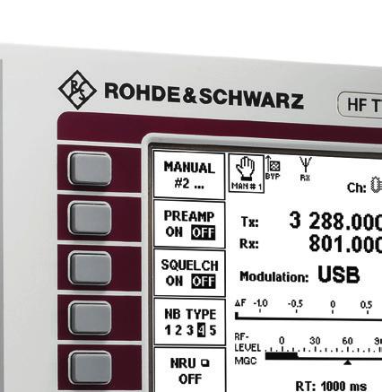
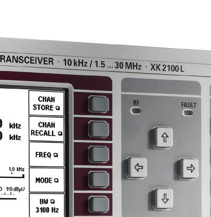
6 User-friendly operation The Series2000 HF radio family is outstanding for its high user-friendliness, featuring menu guidance on a highcontrast, large-size LC graphic display and providing a number of convenient controls and displays such as: Softkeys Cursor keys Step keys (rollkey editor) Message, selection and editing windows Numeric editor Icons for menu and system status indication In addition to plain-text messages, bargraphs are used to indicate the receive field strength, output power, etc. The control functions are logically combined in the menus and can thus be found easily. The clear-cut display makes operation of the Series2000 easy even for the non-specialist. Users with expertise can go to a more complex menu level upon entering a password and configure the equipment as required to suit a wide variety of applications. Suitable for use in harsh environments The Series2000 HF radio family was designed for operation under adverse environmental conditions and can be used not only in fixed stations but also on vehicles and ships. Shock absorbers are available for the XK2100 to protect the units in applications involving high levels of shock and vibration. Proper operation of the system will not be impaired by varying climatic conditions, problematic EMC environments or supply voltage fluctuations. Block diagram of the XK2100 and GX2900 Ctrl FK20xx digitally tuned RF selectors Data GV21xx modem/data interface 150 W amplifier or 500 W/1 kw amplifier interface RF unit/ synthesizer FK2110 EMC filter ALE/APP Telephone adapter PABX, PSTN DTE GM2200 HF modem SERBUS PTT/AF Front panel/ control unit GS2200 ALE processor IF/AF processor PTT/AF Antenna/ATU Power supply Ext. reference EMC filter 21 V to 31 V DC RS-232 RF signals Intercom bus ISB bus AF bus Miscellaneous signal types Data bus RS-485/ RS-422 AF Blower unit PTT Software update Data transmission Remote control External PC and software The base units of the Series2000 systems are equipped with six standard modules and provide spare slots for options (blue). Software updates are conveniently performed from a PC via the RS-232 interface. 6 Series2000_dat_en_ _v0900.indd :22:34

7 Selective level control Optimum matching The usual transmitter power control using broadband directional couplers as sensors can often not be employed, since backdoor power components from neighboring transceivers activate the transmitter power control and thus reduce the transmitter power, although there is no actual mismatch in the line under observation. Problems of this kind are likely to occur in applications where antennas are closely co-sited (e.g. co-location on board ships), or where frequency spacing is very small. Optimum matching of the antennas is achieved by means of the FK2900M for the 500 W and the 1000 W systems, and by means of the FK2100M for the 150 W system. The HF transceivers with selective level control feature narrowband evaluation of the forward and reflected power at the wanted frequency so that the transmitter power control is not affected by RF power coupled in from other transmitters in the system. All ATUs are fully arc-protected against direct lightning strokes. They are tested to withstand arcs of 10 kv/10 ka. An automatic BIT (built-in test) provides fault detection and reporting to the Series2000 transceiver/exciter respectively. The FK2100M can be used for land and naval applications. Is is sea-water and drop resistant and can match antennas with very low ohmic resistance. Microprocessor-controlled tuning allows self-learning of a maximum of 1500 settings that, together with the channels stored in the XK2100 transceiver (including ALE, ITU and 100 silent channels), are retained in non-volatile memory. The stored channels can be called up with very short setting times. FK2100M antenna tuning unit. Rohde & Schwarz R&S Series2000 HF Radio Family 7 Series2000_dat_en_ _v0900.indd :22:35

8 Failsafe power supply High-speed data mode The external power supplies are intended for stationary applications. They are in the form of a primary switchedmode power supply for all three power classes of the transceiver and comply with the relevant safety and EMC regulations. Depending on the system configuration, either with integrated or external ALE and/or HF modem, various interface options such as the FK2110 EMC filter or the GV2130 modem data interface are available for connection to external HF modems, data sources, dataprotection or link processors. The IN4150 and IN4190 were designed for single- or three-phase operation. For special AC supply voltages, e.g. in maritime applications, the BV4190 transformer is available as an option, which can be incorporated in the transceiver rack. When an emergency power supply (e.g. a 24 V battery) is used, AC supply/battery switchover will be effected instantaneously in the event of a power failure, thus ensuring uninterrupted radiocommunications. 1) System expansion options Data link expandability The GV2120 data link interface is provided for connecting an external data terminal set (DTS) that complies with MIL-STD A and STANAG 5511, STANAG Full-duplex or split-site operation For operations at different sites, a GP2000 split site controller is available to control separate transmitter and receiver sites from one center, also allowing ALE, fast data, and HF telephone modes. The base XK2100 transceivers as well as the GX2900 receiver-exciter are already fully prepared to accommodate optional interfaces that are available as plug-in units and are located at the rear of the equipment. Various interface options are available for easy matching and proper connection of external (e.g. customer-provided) HF modems, link processors, data terminal sets or system processors, encryption devices, etc., as well as for the control and operation of system-specific options such as remote control units. 1) At reduced power with 500 W and 1000 W systems. Block diagram: configuration example. Antenna (e.g. AK503) with GM bit/s (HF modem) option with GS2200 (ALE) option XK2100 FK2100 antenna tuning unit Data, control PC 26 V DC IN4000A power supply AC supply or emergency battery With the optional HF modem incorporated in the transceiver, transmission rates of up to 9600 bit/s can be achieved. This allows the trans-mission and reception of data files, for example. 8 Series2000_dat_en_ _v0900.indd :22:36
9 Specifications Transmission Reception R&S XK2500 R&S XK2900 Frequency range 10 khz to 30 MHz 1.5 MHz to 30 MHz 1000 W ± 1 db PEP or CW Input impedance 50 Ω, VSWR < 3 10/30/100 W 1.5 MHz to 30 MHz 500 W ± 1 db PEP or CW (400 W ± 1 db with FK855 ATU) 40/100/500 W > 70 dbc > 70 dbc > 70 dbc typ. 60 dbc > 32 db typ. 60 dbc > 36 db typ. 60 dbc > 36 db R&S XK2100 Frequency range 1.5 MHz to 30 MHz Output power 150 W ± 1 db into 50 Ω, PEP, 100 W VSWR 1.5 ± 1 db CW Power levels Spurious suppression 1) Harmonics suppression Intermodulation products (referenced to PEP) S/N ratio 2) Carrier suppression Suppression of unwanted sidebands Voice compression (VC) 100/500/1000 W Input sensitivity (for S/N = 10 db, f = 0.2 MHz to 30 MHz) Without preamplifier and preselection A1A (CW) J3E (SSB) H3E (AME), 1 khz, m = 60 % With preamplifier, without preselection A1A (CW) J3E (SSB) H3E (AME), 1 khz, m = 60 % Receiving bandwidths 3 db 60 db typ. 70 db typ. 70 db > 60 db > 60 db > 60 db AGC built-in, power increase with radiotelephony Frequency setting decadic in 1 Hz steps Channel memory User-programmable channels 401 Including half-duplex channels 100 (transmit and receive frequencies separately programmable) Fixed programmed channels (ITU) channel numbers between 401 and 2240 (half-duplex) Additional channels for ALE 120 (half-duplex) Response to a 60 db step variation Attack time < 10 ms Decay time 25/150/500 ms, 1 s/3 s (selectable) AF distortion Line output, 0 dbm < 1% Headphones, loudspeaker < 3 % at rated power Weighted S/N ratio (H3E) > 46 db SINAD for 1 mv EMF, weighted with filter in line with CCITT (O.41/P53) Nonlinearities (1.5 MHz to 30 MHz, without preamplifier) Blocking Frequency error Standard (TCXO) < / C Optional (OCXO) < / C, < /day Standard (TCXO) < /year Optional (OCXO) < /year Classes of emission 1) 2) 3) 4) Desensitization Intercept point IP3 Aging A1A (CW), J3E (SSB, USB/LSB), H3E (AME), B8E (ISB), F1B (FSK, AFSK, 50 Bd to 600 Bd, shift 42.5 Hz to 425 Hz), F3E (FM), F3C, A3E (AM) (reception only), J2D (with external modem), MIL-STD A (optional) Measured at < 0.95 fc and > 1.05 fc (fc = center frequency of bandwidth). Measured at f ± 10 %, at maximum rated output power, A1A (CW). At 10 db S/N. At 10 db SINAD. typ μv EMF, BW = 300 Hz 3) typ. 0.4 μv EMF, BW = 2.7 khz 4) typ. 1.0 μv EMF, BW = 6 khz 4) ±25/75/150/200/300/400/500 Hz, ±750/900/1050/1200/1350 Hz, ±1550/1850/2250/3000/4000 Hz ±125/150/215/335/430/650/770 Hz, ±1000/1440/1600/1760/1900 Hz, ±2100/2850/3220/4100 /5100 Hz < 3 db (1 μv to 1 V EMF) > 150 dbc (1 Hz) > 150 dbc (1 Hz) > 150 dbc (1 Hz) typ. 70 db typ. 0.4 μv EMF, BW = 300 Hz 3) typ. 1.0 μv EMF, BW = 2.7 khz 4) typ. 2.7 μv EMF, BW = 6 khz 4) Crossmodulation 3 db signal attenuation (Δf = 30 khz, useful signal 2 mv EMF, interfering signal 5 V EMF) > 20 db SINAD (Δf > 30 khz, BW = 2.7 Hz, useful signal 30 µv, interfering signal 100 mv) typ. 35 dbm (Δf > 30 khz, interfering signals 2 0 dbm) < 10 % (Δf > 30 khz, useful signal 1 mv EMF, interfering signal 4 V EMF, 1 khz, m = 30 %) Noise figure Without preamplifier 17 db With preamplifier 9 db Inherent spurious signals in line with MIL-STD B Immunity to interference Image-frequency rejection typ. 90 db IF rejection typ. 90 db Oscillator reradiation < 10 μv (at antenna input) Protection of receiver input up to 100 V EMF (f < 30 MHz) With digitally tuned RF selectors up to 200 V EMF (f < 30 MHz) Rohde & Schwarz R&S Series2000 HF Radio Family 9 Series2000_dat_en_ _v0900.indd :22:36
10 Power supplies Options FK2020 digitally tuned RF selectors FK2040 digitally tuned RF selectors GS2200 data link processor GM2200 HF modem KL2100 blower unit ( XK2100) GB2000 remote control unit GP2000 remote control processor FK2110 EMC filter ALE/APP attenuation > 20 db at > 10 % from operating frequency attenuation > 40 db at > 10 % from operating frequency automatic link establishment (ALE) in line with ALIS or MIL-STD B, App. A + B, for speech and data transmission advanced multimode HF modem with selectable waveforms up to 9.6 kbit/s in line with STANAG 4285, STANAG 4529, STANAG 4539, Annex B, Section 4, GM2200S (proprietary) required for continuous data transmission with modems for distances > 50 m; class of protection IP42 in line with DIN (IP54 as an option) for establishing split-site configurations APP interface to PABX interface, ALE-DTE interface AC supply Frequency 1.5 MHz to 30 MHz range Recommended FK2100M ATUs NVIS antennas HX002A1/M1 R&S XK2500 Temperature range Operating Storage Humidity Mechanical data Vibration Sinusoidal Random Shock resistance FK2900M FK2900M FK855C1/C3 FK859 HX002 EMI/EMC General data of ATU and antenna R&S XK2100 R&S XK2500 R&S IN V (1 phase + N), 208 V (Δ, 3 phases), 230 V (Y, 3 phases + N) +10 %, 15 %, 47 Hz to 63 Hz max. 4.5 kva max. 6.5 kva max. 5.0 kva General data of power supplies R&S XK2900 R&S XK2900 Temperature MIL-STD-810E, methods and range Operation 25 C to +55 C 25 C to +55 C Storage 40 C to +85 C Humidity MIL-STD-810E, method Mechanical data Vibration EN Sinusoidal (EN ) 5) Random MIL-STD-T (0.01 g2/hz, 10 Hz to 300 Hz, 1.9 g RMS) Shock (MIL-STD-810E, method 516.4, proc. I) 5) EMC MIL-STD-461E MIL-STD-461E CE102, CS101, CE102, CS101, CS114, RE102, CS114, RS101, RS101, RS103 RS103, (CE103, CS102, CS106, RE102) 6) MTBF > 9600 h > 5500 h > 5000 h Class of IP43/20 6) IP43/20 6) protection IP43/32 6) CE conformity in line with EN 60945, ETSI EN /-2/-3 mark (with restrictions) 7) Dimensions XK2100: GX2900: GX2900: W H D in mm (without ( IN2100: VK2500: VK2900: options) ) IN4150: IN4190: Weight (with- XKx: 15 kg GXx: 13 kg GXx: 13 kg out options) ( INx: 9 kg) VKx: 34 kg VKx: 42 kg INx: 24 kg INx: 24 kg R&S IN V (1 phase + N), 208 V (Δ, 3 phases), 230 V (Y, 3 phases + N) +10 %, 15 %, 47 Hz to 63 Hz Input voltage 90 V to 264 V, tolerance 47 Hz to 63 Hz Input power consumption 1 phase max kva max. 2.5 kva 3 phases (Y) max. 3.6 kva 3 phases (Δ) max. 3.0 kva Battery 24 V DC emergency supply Antenna tuning units (ATUs) and antennas R&S XK2100 R&S IN4000A 230 V (1 phase + N) 5) 6) 7) R&S IN4000A R&S IN4150 R&S IN4190 MIL-STD-810F, method 501.4/502.4, EN /2 25 C to +55 C 40 C to +70 C MIL-STD-810F, method MIL-STD-167-1, type 1 MIL-STD-810F, method MIL-STD-810F, MIL-STD-810F, method 516.5, method 516.5, proc. I, EN proc. I MIL-STD-461E: MIL-STD-461E: CE102, CS101, CE101, CE102, CS114, RE101, RE102, RS101, CS101, CS114, RS103 CS115, RE101, RE102, RS101, RS103 Tests in brackets were not verified in conjunction with the IN4000A. Front-panel exciter/rest of transceiver. XK2100: ETSI EN , 7.6, 9.3, 10.7 (see user manual); XK2500/XK2900: ETSI EN , 7.6, 8.3, 9.3, , 10.7 (see user manual); EN (see user manual). 10 Series2000_dat_en_ _v0900.indd :22:36
11 Ordering information Base units External options Designation Type Order No. HF Transceiver 150 W 8) Desktop Model XK2100L Rackmount 19" Adapter XK2100 IN2100 Naval Software Option HF Transceiver 500 W KA KA XK2101S ) Model for installation in 19" racks 9) Model for installation in 19" racks 9), selective level control Naval Software Option HF Transceiver 1000 W XK2500L XK2500L GX2901S ) Model for installation in 19" racks 9) XK2900L Model for installation in 19" racks, selective level control 9) Naval Software Option XK2900L GX2901S Internal options Designation Type Order No. Remote Control Unit GB Remote Control Processor GP System Receiver EK V Transformer BV Power Supply ( XK2100) IN4000A Power Supply 230 V AC; 1 or 3 phases + N/208 V AC; 3-phase Δ Power Supply 220 V DC IN IN Power Supply 230 V AC; 1 or 3 phases + N/208 V AC; 3-phase Δ Antenna Tuning Unit, 150 W IN FK Antenna Tuning Unit, 150 W, naval applications 11) Antenna Tuning Unit, 500 W, naval applications 11) Antenna Tuning Unit, 1 kw, naval applications 11) FK2100M FK855C FK2900M Recommended extras Designation Type Order No. Designation Data Link Processor GS Shock Absorber Software for GS2200 Type Order No. For XK2100 KS MIL-STD B, App. A (ALE) GS2200S For XK2500/XK2900 KS MIL-STD B, App. A + B, linking protection (ALE) ALIS (Rohde & Schwarz standard) GS2201S Service Kit KA Mating Connector Sets ( Series2000) GS2210S Data Link Interface 10) LINK Y + LINK 11 (CLEW SLEW) GV LINK Y (CLEW SLEW) GV HF Modem, multistandard 10) GM Modem Software Rohde & Schwarz kbit/s GM2200S MIL-STD A Section 5.3 (Single Tone) STANAG 4285 GM2201S STANAG 4529 GM2203S MIL-STD B App. C or STANAG 4539 Annex B, Section 4 Further options GM2204S High-Precision Frequency Standard (OCXO) (factory-installed only) Blower unit (for XK2100L) GF KL Digitally Tuned RF Selectors FK Digitally Tuned RF Selectors FK Rx/Tx Interface GS Receiver Input Protection ZW EMC Filter ALE/APP FK GM2202S For XK2100L GK2100 For GB2000 KA2000B For GX2900L KA2900G For VK2500/VK2900 KA2900V For IN4150/IN4190 ZF Further options and accessories on request 8) 9) 10) 11) HF transceivers equipped with front panel for local and remote control. Mating connector sets and cables have to be ordered separately. Requires GF2010 high-precision frequency standard. Requires naval software option. Rohde & Schwarz R&S Series2000 HF Radio Family 11 Series2000_dat_en_ _v0900.indd :22:36
12 Service that adds value Worldwide Local and personalized Customized and flexible Uncompromising quality Long-term dependability About Rohde & Schwarz The Rohde & Schwarz electronics group is a leading supplier of solutions in the fields of test and measurement, broadcasting, secure communications, and radiomonitor ing and radiolocation. Founded more than 80 years ago, this independent global company has an extensive sales network and is present in more than 70 countries. The company is headquartered in Munich, Germany. Sustainable product design Environmental compatibility and eco-footprint Energy efficiency and low emissions Longevity and optimized total cost of ownership Certified Quality Management ISO 9001 Certified Environmental Management ISO Rohde & Schwarz GmbH & Co. KG R&S is a registered trademark of Rohde & Schwarz GmbH & Co. KG Trade names are trademarks of the owners PD Version October 2014 (fi) R&S Series2000 HF Radio Family Data without tolerance limits is not binding Subject to change Rohde & Schwarz GmbH & Co. KG Munich, Germany PDP 1 en Regional contact Europe, Africa, Middle East customersupport@rohde-schwarz.com North America TEST RSA ( ) customer.support@rsa.rohde-schwarz.com Latin America customersupport.la@rohde-schwarz.com Asia Pacific customersupport.asia@rohde-schwarz.com China customersupport.china@rohde-schwarz.com Series2000_dat_en_ _v0900.indd :22:37
HF Transmit/Receive Broadband System XB 2900
 Data sheet HF Transmit/Receive Broadband System XB 2900 Especially designed for naval operational environment Full HF frequency band (2 MHz to 30 MHz) for voice, data, and ALE operation Flexible system
R&S EB500 Monitoring Receiver Specifications
 Radiomonitoring & Radiolocation Data Sheet 01.02 R&S EB500 Monitoring Receiver Specifications CONTENTS Definitions... 3 Specifications... 4 Frequency...4 Linearity...4 Interference rejection...4 Noise
TMR6200 HF Naval Digital Transceivers
 TMR6200 HF Naval Digital Transceivers One or Two High Performance 500 W/1 kw Transceivers in a Single Cabinet 125 W High Performance Transceiver In a 4U/19-inch Chassis Outstanding RF Performance Optimized
R&S FU129 Antenna Filter Unit Antenna switching, rotator control and signal attenuation, amplification and filtering
 Radiomonitoring & Radiolocation Product Brochure 02.01 R&S FU129 Antenna Filter Unit Antenna switching, rotator control and signal attenuation, amplification and filtering R&S FU129 Antenna Filter Unit
R&S RSC Step Attenuator Specifications
 R&S RSC Step Attenuator Specifications Data Sheet Version 05.00 CONTENTS Definitions... 3 Specifications... 4 Step attenuator, 139 db, 1 db steps, DC to 6 GHz (models.03 and.13)... 4 Step attenuator, 139.9
R&S ZVT Vector Network Analyzer Specifications
 ZVT_dat-sw_en_0758-065-22_v0900_cover.indd Data Sheet 09.00 Test & Measurement R&S ZVT Vector Network Analyzer Specifications 06.03.205 5:50:4 CONTENTS Definitions... 3 Specifications... 4 Measurement
R&S FSC Spectrum Analyzer Specifications
 R&S FSC Spectrum Analyzer Specifications year Data Sheet Version 03.00 CONTENTS Base unit... 3 Frequency... 3 Sweep time... 3 Bandwidths... 3 Level... 4 Trigger functions... 5 Tracking generator (model.13/.16
R&S ZV-Z5x Calibration Units Specifications
 R&S ZV-Z5x Calibration Units Specifications Test & Measurement Data Sheet 10.00 Specifications apply under the following conditions: Sufficient warm-up time (approx. 15 minutes) at ambient temperature,
R&S ZVT Vector Network Analyzer Specifications
 R&S ZVT Vector Network Analyzer Specifications Test & Measurement Data Sheet 08.00 CONTENTS Definitions... 3 Specifications... 4 Measurement range...4 Measurement speed...5 Measurement accuracy...6 Effective
R&S ZNBT8 Vector Network Analyzer Specifications
 E stablished 1981 Advanced Test Equipment Rentals www.atecorp.com 800-404-ATEC (2832) ZNBT8_dat-sw_en_3606-9727-22_v0200_cover.indd 1 Data Sheet 02.00 Test & Measurement R&S ZNBT8 Vector Network Analyzer
R&S EM510 HF Digital Wideband Receiver Efficient and versatile solution for radiomonitoring
 EM510_bro_en_5213-7731-32_v0200.indd 1 Product Brochure 02.00 Radiomonitoring & Radiolocation R&S EM510 HF Digital Wideband Receiver Efficient and versatile solution for radiomonitoring 27.05.2015 16:01:58
Attenuators and Matching Pads, Terminations 75 mw to 1000 W, DC to 18 GHz
 Product Brochure Version 8. Attenuators and Matching Pads, Terminations 75 mw to W, DC to 8 GHz Attenuators_dat-bunt_en_758-96_3_v8.indd 3.3.7 7:33:39 Attenuators As a rule, the reflection coefficient
Monitoring Receiver R&S ESMB
 Data sheet Version 03.00 Monitoring Receiver R&S ESMB September 2003 Military and civil monitoring from 9 khz to 3 GHz ITU-compliant measurements The Monitoring Receiver R&S ESMB is ideally suited for
EK895/ EK896 Digital VLF-HF Receivers
 Data sheet EK895/ EK896 Digital VLF-HF Receivers For all shortwave applications from 10 khz to 30 MHz Compact DSP-based receivers for the following applications: Radiomonitoring and radio detection Radiocommunications
R&S CMU-Z10/-Z11 Antenna Coupler/ RF Shielding Cover Simple interference-free testing of all mobiles
 R&S CMU-Z1/-Z11 Antenna Coupler/ RF Shielding Cover Simple interference-free testing of all mobiles Test & Measurement Data Sheet 3. R&S CMU-Z1 /-Z11/-Z1/-Z13/-Z1 At a glance Anyone engaged in mobile phone
R&S ZNC Vector Network Analyzer Specifications
 ZNC3_dat-sw_en_5214-5610-22_v0300_cover.indd 1 Data Sheet 03.00 Test & Measurement R&S ZNC Vector Network Analyzer Specifications 04.09.2012 13:39:47 CONTENTS Definitions... 3 Measurement range... 4 Measurement
: Triple PLL, lowest reference frequency 10 khz. : ± 5 khz in 10 Hz steps, synthesized.
 PETER DE CONINCK HAGENUK RX 1001MVB RECEIVER ONL4234 SERIAL N 5820-310-6162 BELGIAN SWL DRAWING N 97 8 2.164 Technical data Frequency range Frequency resolution Frequency tuning Frequency synthesizer Frequency
MILnews. IP-based split-site operation with the R&S M3SR Series4100 HF radios. Offprint from MILnews 12. Electronics for security and defense
 MILnews Electronics for security and defense Offprint from MILnews 12 IP-based split-site operation with the R&S M3SR Series4100 HF radios IP-based split-site operation with the R&S M3SR Series4100 HF
R&S CBT/R&S CBT32 Bluetooth Tester Specifications
 Established 1981 Advanced Test Equipment Rentals www.atecorp.com 800-404-ATEC (2832) R&S CBT/R&S CBT32 Bluetooth Tester Specifications Test & Measurement Data Sheet 06.00 CONTENTS Unit specifications...
R&S ZNB Vector Network Analyzer Specifications
 Umschlag_ZNB4-8_dat-sw_en_5214-5384-22.indd 1 Data Sheet 02.00 Test & Measurement R&S ZNB Vector Network Analyzer Specifications 07.11.2011 10:03:35 CONTENTS Definitions... 3 Measurement range... 4 Measurement
R&S ZN-Z5x Calibration Units Specifications. Data Sheet V03.00
 R&S ZN-Z5x Calibration Units Specifications Data Sheet V03.00 CONTENTS Definitions... 4 Specifications... 6 Model description R&S ZN-Z5x... 6 Model description R&S ZN-Z15x... 7 Input power limits... 7
R&S ESCI/ESCI7 EMI Test Receiver Specifications
 R&S ESCI/ESCI7 EMI Test Receiver Specifications Test & Measurement Data Sheet 03.00 Specifications Specifications apply under the following conditions: 15 minutes warm-up time at ambient temperature, specified
R&S ZV-Z5x Calibration Units Specifications
 R&S ZV-Z5x Calibration Units Specifications Test & Measurement Data Sheet 09.01 Specifications apply under the following conditions: Sufficient warm-up time (approx. 15 minutes) at ambient temperature,
R&S ZVA-Zxx Millimeter-Wave Converters Network analysis up to 500 GHz
 ZVA-Zxx_bro_en_5214-2033-12.indd 1 Product Brochure 06.02 Test & Measurement R&S ZVA-Zxx Millimeter-Wave Converters Network analysis up to 500 GHz 28.10.2014 21:05:04 R&S ZVA-Zxx Millimeter-Wave Converters
 Options and their applications Extensions for basic model OCXO Reference Oscillator For long-term stability OCXO Reference Oscillator For extremely high long-term stability Duplex Modulation Meter Allows
R&S ZN-Zxxx Calibration Units Specifications. Data Sheet V04.00
 R&S ZN-Zxxx Calibration Units Specifications Data Sheet V04.00 Version 03.00, January 2019 CONTENTS Definitions... 4 Specifications... 6 Model description R&S ZN-Z5x... 6 Model description R&S ZN-Z15x...
R&S TS8997 Regulatory Test System for Wireless Devices
 R&S TS8997 Regulatory Test System for Wireless Devices Product Brochure Version 03.01 ETSI EN 300328 V1.8.1/ETSI EN 301893 V1.7.1 compliance tests in the 2.4/5 GHz band TS8997_bro_en_3606-8095-12_v0301.indd
R&S SMC100A Signal Generator Specifications
 R&S SMC100A Signal Generator Specifications Test & Measurement Data Sheet 01.00 CONTENTS Key features... 3 Specifications... 4 RF characteristics...4 Frequency...4 Frequency sweep...4 Reference frequency...4
Vector Network Analyzers ZVB
 Specifications Version 05.00 Vector Network Analyzers ZVB September 2005 Specifications MEASUREMENT RANGE...3 MEASUREMENT SPEED...5 MEASUREMENT ACCURACY...6 EFFECTIVE SYSTEM DATA...8 TEST PORT OUTPUT...8
Noise Figure Measurement Applications Specifications
 Noise Figure Measurement Applications Specifications R&S FSW-K30 R&S FSWP-K30 R&S FPS-K30 R&S FSV-K30 R&S FPL1-K30 Data Sheet Version 02.02 CONTENTS Definitions... 3 Specifications... 4 Frequency... 4
R&S NRPM Over-the-Air (OTA) Power Measurement Solution For 5G, WLAN IEEE ad and IEEE ay
 Power Measurement Solution For 5G, WLAN IEEE ad and IEEE ay") year Product Brochure Version 0.00 R&S NRPM Over-the-Air (OTA) Power Measurement Solution For 5G, WLAN IEEE 80.ad and IEEE 80.ay NRPM_bro_en_607-4687-_v000.indd 8.0.09 5:59:08 R&S NRPM Over-the-Air (OTA)
year Product Brochure Version 0.00 R&S NRPM Over-the-Air (OTA) Power Measurement Solution For 5G, WLAN IEEE 80.ad and IEEE 80.ay NRPM_bro_en_607-4687-_v000.indd 8.0.09 5:59:08 R&S NRPM Over-the-Air (OTA)
Using measurement methods described in Australian/New Zealand Standard AS/NZS 4770:2000
 Barrett 2050 HF transceiver Using measurement methods described in Australian/New Zealand Standard AS/NZS 4770:2000 General Specifications Equipment Standards Transmit frequency range Receive frequency
IC-F7000. Advanced selective call and ALE make HF communication easier than ever!
 Page 1 of 5 HF TRANSCEIVER IC-F7000 Advanced selective call and ALE make HF communication easier than ever! The IC-F7000 is an HF land mobile transceiver especially designed forlong distance communications.
R&S FSH4/8 Spectrum Analyzer Specifications
 R&S FSH4/8 Spectrum Analyzer Specifications Test & Measurement Data Sheet 02.00 CONTENTS Specifications... 3 Frequency...3 Sweep time...3 Bandwidths...4 Level...4 Trigger functions...5 Inputs and outputs...6
R&S UMS175 Compact Radiomonitoring System High performance for outdoor deployment
 UMS175_bro_en_3607-1488-12_v0201.indd 1 Product Brochure 02.01 Radiomonitoring & Radiolocation R&S UMS175 Compact Radiomonitoring System High performance for outdoor deployment 11.02.2016 09:50:15 R&S
Spectrum Analyzer FSL
 Specifications Version 02.00 Spectrum Analyzer FSL August 2005 Specifications Specifications Specifications apply under the following conditions: 15 minutes warm-up time at ambient temperature, specified
R&S FS-K112PC NFC Measurement Software Specifications
 FS_K112-PC_dat-sw_3606-7047-22_cover.indd 1 Data Sheet 03.00 Test & Measurement R&S FS-K112PC NFC Measurement Software Specifications 06.10.2014 18:19:15 CONTENTS Definitions... 3 Specifications... 4 Minimum
2026Q CDMA/GSM Interferer MultiSource Generator
 Signal Sources 2026Q CDMA/GSM Interferer MultiSource Generator The 2026Q is designed to work with a radio test set to provide a fully integrated radio receiver test solution for cellular and PCS systems
R&S MNT100 RF Interference Locator Specifications
 R&S MNT100 RF Interference Locator Specifications Data Sheet Version 02.00 CONTENTS Specifications... 3 RF data... 3 Noise figure, DANL... 3 Phase noise... 3 Sensitivity (demodulation path) with ITU-T
Analog Modulation Analysis (AM/FM/φM) Specifications
 Specifications") Analog Modulation Analysis (AM/FM/φM) Specifications R&S FSW-K7 R&S ESW-K7 R&S FSWP-K7 R&S FSV-K7 R&S FSL-K7 R&S FPS-K7 R&S FPL1-K7 R&S VSE-K7 Data Sheet Version 06.00 CONTENTS Definitions... 3 Specifications...
Analog Modulation Analysis (AM/FM/φM) Specifications R&S FSW-K7 R&S ESW-K7 R&S FSWP-K7 R&S FSV-K7 R&S FSL-K7 R&S FPS-K7 R&S FPL1-K7 R&S VSE-K7 Data Sheet Version 06.00 CONTENTS Definitions... 3 Specifications...
Spectrum Analyzer R&S FS300
 Spectrum Analyzer R&S FS300 9 khz to 3 GHz The new product family from Rohde & Schwarz Professional test equipment for laboratory, service and production The R&S FS300 is a highly accurate spectrum analyzer
Signal Generator SML
 Signal Generator SML Economy at its best 9 khz to 1.1 GHz/2.2 GHz/3.3 GHz SSB phase noise: < 122 dbc (1 Hz) (at f = 1 GHz, f = 20 khz) Setting times
ERX 3003 / RX 3003 Pushing the Limits 24 khz* wideband capability
 ERX 3003 / RX 3003 HF Exciter / VLF-HF Receiver ERX 3003 / RX 3003 Pushing the Limits 24 khz* wideband capability Software Defined HF Exciter/VLF-HF Receiver FEATURES Frequency range: 1.5 MHz 30 MHz transmit
Modulation Analyzer FMAB
 Data sheet Version 02.00 Modulation Analyzer FMAB The specialist for sound broadcast signals from 50 khz to 1360 MHz December 2003 Built-in precision stereo decoder both for internal FM stereo decoding
R&S CLGD DOCSIS Cable Load Generator Multichannel signal generator for DOCSIS 3.1 downstream and upstream
 CLGD_bro_en_3607-0123-12_v0200.indd 1 Product Brochure 02.00 Broadcast & Media Test & Measurement R&S CLGD DOCSIS Cable Load Generator Multichannel signal generator for downstream and upstream 24.07.2015
R&S Series4200 Software Defined Radios VHF/UHF Radio Family for ATC Communications
 Secure Communications Product Brochure 05.00 R&S Series4200 Software Defined Radios VHF/UHF Radio Family for ATC Communications R&S Series4200 Software Defined Radios At a glance The R&S Series4200 represents
R&S FPC Spectrum Analyzer Specifications
 R&S FPC Spectrum Analyzer Specifications year Data Sheet Version 04.00 CONTENTS Definitions... 3 Specifications... 4 Frequency... 4 Sweep time... 4 Bandwidth... 4 Level... 5 Trigger functions... 6 Tracking
Barrett 950 HF transceiver specifications Using measurement methods described in European Telecommunication Standard
 Barrett 950 HF transceiver specifications Using measurement methods described in European Telecommunication Standard 300 373. General Specifications Equipment Standards Transmit frequency range Receive
Evolution of the Modern Receiver in a Crowded Spectrum Environment White Paper
 Evolution of the Modern Receiver in a Crowded Spectrum Environment White Paper The International Telecommunications Union Radiocommunications working group (ITU-R) outlines recommendations for the regulations
Voltage Sensors URV5-Z
 Data sheet Version 05.00 Voltage Sensors URV5-Z May 2005 Universal voltage measurements from RF to microwaves The voltage sensors of the URV5-Z series are indispensable tools in RF and microwave laboratories,
Signal Generators SMY
 NEW up to 25 dbm RF sweep 9 khz to 1040/2080 MHz Signal Generators SMY Versatility and low cost can go hand in hand Frequency resolution 1 Hz Level range 140 to +19 dbm, overrange up to 25 dbm (option)
R&S TS-EMF EMF Measurement System Easy, frequency-selective measurement of EMF emissions
 TS-EMF_dat_en_0758-2777-12_v0501.indd 1 Product Brochure 05.01 Test & Measurement R&S TS-EMF EMF Measurement System Easy, frequency-selective measurement of EMF emissions 11.04.2016 09:35:59 R&S TS-EMF
Signal Generator SMA100A
 Product brochure Version 02.01 Signal Generator SMA100A November 2006 The new standard of excellence in the analog signal generator class Excellent signal quality Ideal for use in production All-purpose
Radio Base Station ND 950
 Radio Base Station ND 950 Compact and easy upgradable ACCESSNET the innovative Trunked Radio System from Rohde & Schwarz, has gained high acceptance on the world market due to its superb features and economical
R&S ENV216 Two-Line V-Network For disturbance voltage measurements on single-phase EUTs
 R&S ENV216 Two-Line V-Network For disturbance voltage measurements on single-phase EUTs Test & Measurement Data Sheet 03.00 R&S ENV216 Two-Line V-Network At a glance The R&S ENV216 two-line V-network meets
Signal Generator SMA 100A
 Specifications Version 01.01 Signal Generator SMA 100A April 2006 Specifications CONTENTS CONTENTS... 2 KEY FEATURES... 3 SPECIFICATIONS... 4 RF CHARACTERISTICS... 4 Frequency... 4 Frequency sweep... 4
R&S DF-ATC-S ATC DF System Solution Accurate and reliable direction finding for civil and military air traffic control
 Product Brochure Version 0.00 R&S DF-ATC-S ATC DF System Solution Accurate and reliable direction finding for civil and military air traffic control DF-ATC-S_bro_en_525-0792-2_v000.indd 20.02.208 :9:40
Signal Sources. 2026Q CDMA Interferer Multisource Generator. Advanced Test Equipment Rentals ATEC (2832)
") Signal Sources Established 1981 Advanced Test Equipment Rentals www.atecorp.com 800-404-ATEC (2832) 2026Q CDMA Interferer Multisource Generator The 2026Q is designed to work with a radio test set to provide
Signal Sources Established 1981 Advanced Test Equipment Rentals www.atecorp.com 800-404-ATEC (2832) 2026Q CDMA Interferer Multisource Generator The 2026Q is designed to work with a radio test set to provide
Guide Version Five techniques for fast, accurate power integrity measurements
 Guide Version 01.00 Five techniques for fast, accurate power integrity measurements Rail voltages are getting smaller, and tolerances are decreasing. As a result, making accurate power rail measurements
EB200 Miniport Receiver
 Data sheet Version 04.00 EB200 Miniport Receiver November 2006 Portable radiomonitoring from 10 khz to 3 GHz Ergonomic design for portable use Continuous frequency range from 10 khz to 3 GHz Detection
Handheld Spectrum Analyzer R&S FSH3
 Handheld Spectrum Analyzer R&S FSH3 100 khz to 3 GHz Fourth Edition July 2003i Spectrum analysis anywhere, anytime The R&S FSH3 is the ideal spectrum analyzer for rapid, high-precision, cost-effective
RF Signal Generator SM300
 RF Signal Generator SM300 9 khz to 3 GHz With compliments Helmut Singer Elektronik www.helmut-singer.de info@helmut-singer.de fon +49 241 155 315 fax +49 241 152 066 Feldchen 16-24 D-52070 Aachen Germany
Handheld Spectrum Analyzer R&S FSH 3
 Handheld Spectrum Analyzer R&S FSH 3 100 khz to 3 GHz Fifth Edition December 2003i Spectrum analysis anywhere, anytime The R&S FSH3 is the ideal spectrum analyzer for rapid, high-precision, cost-effective
Bring satellites into your lab: GNSS simulators from the T&M expert.
 Bring satellites into your lab: GNSS simulators from the T&M expert. www.rohde-schwarz.com/gnss-solutions Your challenge GNSS receiver tests can only be conclusive when they are performed under realistic
R&S M3AR MR6000R R&S M3AR MR6000L Software Defined Radios Specifications
 Secure Communications Data Sheet 03.00 R&S M3AR MR6000R R&S M3AR MR6000L Software Defined Radios Specifications CONTENTS Specifications for the fixed-frequency base unit... 3 Built-in interfaces... 3 General
R&S ZV-Z3xx T-Checker Specifications
 ZV-Z3xx_dat-sw_en_3607-0575-22_cover.indd 1 Data Sheet 01.00 Test & Measurement R&S ZV-Z3xx T-Checker Specifications 17.06.2014 15:14:20 CONTENTS Definitions... 3 Specifications... 4 Measurement range...
2026A/B 10 khz to 2.05/2.51 GHz MultiSource Generator
 Signal Sources 2026A/B 10 khz to 2.05/2.51 GHz MultiSource Generator Up to three fully functional signal generators in one unit offering a unique solution for complex tests on receivers, components and
DIRECTORATE OF COORDINATION POLICE WIRELESS MINISTRY OF HOME AFFAIRS GOVERNMENT OF INDIA
 DIRECTORATE OF COORDINATION POLICE WIRELESS MINISTRY OF HOME AFFAIRS GOVERNMENT OF INDIA TECHNICAL SPECIFICATION OF HF TRANSCEIVER & MANPACK TECHNICAL STANDARD No. DCPW/ TS-HF/01/13 Issue: January, 2013
Digital HF Receiver WJ-8723
 Developmental Specification WATKINS-JOHNSON April 1996 Digital HF Receiver WJ-8723 Description The WJ-8723 is a fully synthesized, general-purpose HF receiver that monitors RF communications from 5 khz
Power Added Efficiency Measurement with R&S ZNB/ R&S ZVA
 Power Added Efficiency Measurement with R&S ZNB/ R&S ZVA Application Note Products: R&S ZNB R&S ZVA Power Added Efficiency (PAE) is a key parameter for the characterization of an amplifier. This application
Handheld Spectrum Analyzer R&S FSH khz to 3 GHz
 Handheld Spectrum Analyzer R&S FSH3 100 khz to 3 GHz Spectrum analysis anywhere, anytime The R&S FSH3 is the ideal spectrum analyzer for rapid, high-precision, cost-effective signal investigations. It
Signal Sources. 2026A/B 10 khz to 2.05/2.51 GHz MultiSource Generator.
 Signal Sources 2026A/B 10 khz to 2.05/2.51 GHz MultiSource Generator Up to three fully functional signal generators in one unit offering a unique solution for complex tests on receivers, components and
R&S ZV-Z135 Calibration Kit Specifications
 R&S ZV-Z135 Calibration Kit Specifications Test & Measurement Data Sheet 01.01 CONTENTS Definitions... 3 Specifications... 4 Mechanical data... 4 Electrical data of R&S ZV-Z135 (3.5 mm, female)... 4 Electrical
3521 B 6 Vehicle Set VHF FM VEHICLE RADIO. VEHICLE SETS
 www.radmor.com RADMOR S.A. Hutnicza 3 81-212 Gdynia, Poland Foreign Customers Department: tel. +4858 69 96 621, fax: +4858 69 96 622 e-mail: export@radmor.com.pl VHF FM VEHICLE RADIO 3521 B 6 Vehicle Set
Technical Data. Digital HF Receiver WJ-8712A WATKINS-JOHNSON. Features
 May 1996 Technical Data WATKINS-JOHNSON Digital HF Receiver WJ-8712A The WJ-8712A is a fully synthesized, general-purpose HF receiver for surveillance and monitoring of RF communications from 5 khz to
Measurement Setup for Phase Noise Test at Frequencies above 50 GHz Application Note
 Measurement Setup for Phase Noise Test at Frequencies above 50 GHz Application Note Products: R&S FSWP With recent enhancements in semiconductor technology the microwave frequency range beyond 50 GHz becomes
TS-590SG HF/ 50MHz All-Mode TRANSCEIVER_
 New Product Release Information Oct 2014 TS-590SG HF/ 50MHz All-Mode TRANSCEIVER_ Kenwood introduces Updated to new G version new HF/50MHz All-Mode Transceiver Four years ago we launched our best-selling
R&S EB500 Monitoring Receiver High-performance radiomonitoring from 9 khz to 6 GHz
 Radiomonitoring & Radiolocation Product Brochure 01.04 R&S EB500 Monitoring Receiver High-performance radiomonitoring from 9 khz to 6 GHz R&S EB500 Monitoring Receiver At a glance The R&S EB500 monitoring
Handheld Spectrum Analyzer R&S FSH3
 Handheld Spectrum Analyzer R&S FSH3 100 khz to 3 GHz Third Edition March 2003i Spectrum analysis anywhere, anytime The R&S FSH3 is the ideal spectrum analyzer for rapid, high-precision, cost-effective
R&S NRT Power Reflection Meter Family R&S NRT2 and R&S NRT-Zxx
 R&S NRT Power Reflection Meter Family R&S NRT2 and R&S NRT-Zxx Product Brochure Version 01.00 year NRT_bro_en_5215-0986-12_v0100.indd 1 07.08.2017 10:45:57 R&S NRT Power Reflection Meter Family At a glance
Power Meter NRVS. Power, level and voltage measurements from DC to 40 GHz
 Power Meter NRVS Power, level and voltage measurements from DC to 40 GHz Accurate, general-purpose, easy-to-use Intelligent measuring heads: just plug them in and measure DC frequency input for tracking
R&S FSV Signal Analyzer Specifications
 R&S FSV Signal Analyzer Specifications Test & Measurement Data Sheet 01.00 CONTENTS Specifications... 3 Frequency...3 Sweep time...4 Resolution bandwidths...4 Level...5 Measurement speed...7 Trigger functions...8
R&S ZVL Vector Network Analyzer Specifications
 R&S ZVL Vector Network Analyzer Specifications Data Sheet Version 10.00 CONTENTS Definitions... 3 Specifications... 4 Measurement range... 4 Measurement speed... 4 Measurement accuracy... 5 Effective system
R&S SMB100N SIGNAL GENERATOR
 R&S SMB100N SIGNAL GENERATOR PERFORMANCE SPECIFICATIONS VERSION 02.00, SEPTEMBER 2009 CONTENTS Specifications...3 Definitions... 3 RF performance... 4 Frequency... 4 Frequency sweep... 4 Reference frequency...
R&S SMB100A RF and Microwave Signal Generator Versatile, compact, up to 40 GHz; 170 GHz with upconverter
 R&S SMB100A RF and Microwave Signal Generator Versatile, compact, up to 40 GHz; 170 GHz with upconverter SMB100A_bro_en_5213_8396_12_v0600_neu.indd 1 Product Brochure 06.00 Test & Measurement year 23.03.2016
R&S TS-PSAM Analog Source and Measurement Module Scanning multimeter and data acquisition unit
 TS-PSAM_bro_en_0758-0580-12.indd 1 Product Brochure 03.00 Test & Measurement R&S TS-PSAM Analog Source and Measurement Module Scanning multimeter and data acquisition unit 12.12.2013 15:34:44 R&S TS-PSAM
Receiver requirements for a TDOA-based radiolocation system
 Receiver_requirements_app-bro_en_3606-9162-92.indd 1 Receiver requirements for a TDOA-based radiolocation system Radiomonitoring & Radiolocation Application Brochure 01.00 Receiver requirements for a TDOA-based
R&S SMA100A Signal Generator The new standard of excellence in the analog signal generator class
 SMA100A_bro_en_5213-6412-12.indd 1 Product Brochure 06.01 Test & Measurement R&S SMA100A Signal Generator The new standard of excellence in the analog signal generator class 04.06.2013 10:13:49 R&S SMA100A
MICOM High Grade Solutions
 MICOM High Grade Solutions Used by governmental customers throughout the world. Professional High grade modular solutions! MICOM -3 MICOM-2 MICOM HF Products & Sub-Systems B.B Antenna PSTN/PABX 125/500/1000
R&S FSV Signal and Spectrum Analyzer Specifications
 R&S FSV Signal and Spectrum Analyzer Specifications Test & Measurement Data Sheet 02.02 CONTENTS Specifications... 3 Frequency...3 Sweep time...4 Resolution bandwidths...4 Level...5 Measurement speed...8
Signal Sources. 2026A/B 10 khz to 2.05/2.51 GHz MultiSource Generator
 Signal Sources 2026A/B 10 khz to 2.05/2.51 GHz MultiSource Generator Up to three fully functional signal generators in one unit offering a unique solution for complex tests on receivers, components and
ESU EMI Test Receiver
 Version 02.00 ESU EMI Test Receiver October 2007 Data sheet CONTENTS BASE UNIT...3 FREQUENCY...3 RECEIVER SCAN...4 SWEEP...4 PRESELECTION...4 IF AND RESOLUTION BANDWIDTHS...5 LEVEL...5 I/Q DATA...11 AUDIO
R&S ESRP EMI Test Receiver Specifications
 R&S ESRP EMI Test Receiver Specifications Test & Measurement Data Sheet 01.01 CONTENTS Definitions... 3 Specifications... 4 Frequency... 4 Preselection and preamplifier (R&S ESRP-B2 option)... 6 RF preamplifier
Measuring Receiver FSMR
 Product brochure Version 01.00 02.00 Measuring Receiver FSMR November April 2004 2006 All-in-one solution for the calibration of signal generators and attenuators Frequency range from 20 Hz to 3/26.5/50
Technical Data. VXI HF Receiver WJ-8721 WATKINS-JOHNSON. Features
 May 1996 Technical Data WATKINS-JOHNSON VXI HF Receiver WJ-8721 The WJ-8721 is a fully synthesized, general-purpose HF receiver for surveillance, monitoring and direction finding for RF communi-cations
Noise Figure Measurement in the 60 GHz Range Application Note
 Noise Figure Measurement in the 60 GHz Range Application Note Products: R&S FSU67 Noisecom Noise Figure Test Set - NC5115-60G - NC5115-60GT This application note describes how noise figure and gain of
FSH3 100 khz to 3 GHz FSH6 100 khz to 6 GHz First Edition May 2004i
 Handheld Spectrum Analyzer FSH FSH3 100 khz to 3 GHz FSH6 100 khz to 6 GHz First Edition May 2004i Spectrum analysis anywhere, anytime on earth and in space The FSH is the ideal spectrum analyzer for rapid,
Complimentary Reference Material
 Complimentary Reference Material This PDF has been made available as a complimentary service for you to assist in evaluating this model for your testing requirements. TMG offers a wide range of test equipment
R&S ZVH Cable and Antenna Analyzer Specifications
 Umschlag_ZVH_dat-sw_v0300.indd 1 Data Sheet 03.00 Test & Measurement R&S ZVH Cable and Antenna Analyzer Specifications 18.05.2011 11:30:50 CONTENTS Definitions... 3 Specifications of the R&S ZVH cable
R&S MNT100 RF Interference Locator
 R&S MNT100 RF Interference Locator Product Brochure Version 02.00 Radiolocation in mobile networks From the experts MNT100_bro_en_5215-3762-12_v0200.indd 1 21.01.2019 09:37:04 R&S MNT100 RF Interference