R&S FS-K112PC NFC Measurement Software Specifications
|
|
|
- Eileen Preston
- 6 years ago
- Views:
Transcription
1 FS_K112-PC_dat-sw_ _cover.indd 1 Data Sheet Test & Measurement R&S FS-K112PC NFC Measurement Software Specifications :19:15
2 CONTENTS Definitions... 3 Specifications... 4 Minimum system requirements for R&S FS-K112PC software... 4 Running on a PC... 4 Measurement parameters... 4 Result display... 4 General results... 4 NFC-A specific results... 4 NFC-B specific results... 5 NFC-F specific results... 5 R&S FSL/ZVL/FSV/FSW... 6 Frequency... 6 Level... 6 Signal acquisition... 6 R&S RTO input source... 6 Frequency... 6 Level... 6 Signal acquisition... 6 R&S FSV/FSL/FSW measurement uncertainty (nominal)... 7 NFC-A specific parameters... 7 NFC-B specific parameters... 7 NFC-F 212kB specific parameters... 7 NFC-F 424kB specific parameters... 7 R&S ZVL measurement uncertainty (nominal)... 8 NFC-A specific parameters... 8 NFC-B specific parameters... 8 NFC-F 212kB specific parameters... 8 NFC-F 424kB specific parameters... 8 R&S RTO measurement uncertainty (nominal)... 9 NFC-A specific parameters... 9 NFC-B specific parameters... 9 NFC-F 212kB specific parameters... 9 NFC-F 424kB specific parameters... 9 Ordering information The specifications of the R&S FS-K112PC NFC Measurement Software are based on the data sheet specifications of the R&S FSV, R&S FSW and R&S FSL signal and spectrum analyzers, the R&S ZVLvector network analyzer and the R&S RTO digital oscilloscope, have not been checked separately and are not verified during instrument calibration. Measurement uncertainties are given as 95 % confidence intervals. The specified level measurement errors do not take into account systematic errors due to reduced signal to noise ratio (S/N). Chip rates are specified in Mcps (million chips per second), whereas bit rates and symbol rates are specified in kbps (thousand bits per second) or ksps (thousand symbols per second). Mcps, kbps and ksps are not SI units. 2 Rohde & Schwarz R&S FS-K112PC NFC Measurement Software

3 Definitions General Product data applies under the following conditions: Three hours storage at ambient temperature followed by 30 minutes warm-up operation Specified environmental conditions met Recommended calibration interval adhered to All internal automatic adjustments performed, if applicable Specifications with limits Represent warranted product performance by means of a range of values for the specified parameter. These specifications are marked with limiting symbols such as <,, >,, ±, or descriptions such as maximum, limit of, minimum. Compliance is ensured by testing or is derived from the design. Test limits are narrowed by guard bands to take into account measurement uncertainties, drift and aging, if applicable. Specifications without limits Represent warranted product performance for the specified parameter. These specifications are not specially marked and represent values with no or negligible deviations from the given value (e.g. dimensions or resolution of a setting parameter). Compliance is ensured by design. Typical data (typ.) Characterizes product performance by means of representative information for the given parameter. When marked with <, > or as a range, it represents the performance met by approximately 80 % of the instruments at production time. Otherwise, it represents the mean value. Nominal values (nom.) Characterize product performance by means of a representative value for the given parameter (e.g. nominal impedance). In contrast to typical data, a statistical evaluation does not take place and the parameter is not tested during production. Measured values (meas.) Characterize expected product performance by means of measurement results gained from individual samples. Uncertainties Represent limits of measurement uncertainty for a given measurand. Uncertainty is defined with a coverage factor of 2 and has been calculated in line with the rules of the Guide to the Expression of Uncertainty in Measurement (GUM), taking into account environmental conditions, aging, wear and tear. Device settings and GUI parameters are designated with the format parameter: value. Typical data as well as nominal and measured values are not warranted by Rohde & Schwarz. Rohde & Schwarz R&S FS-K112PC NFC Measurement Software 3
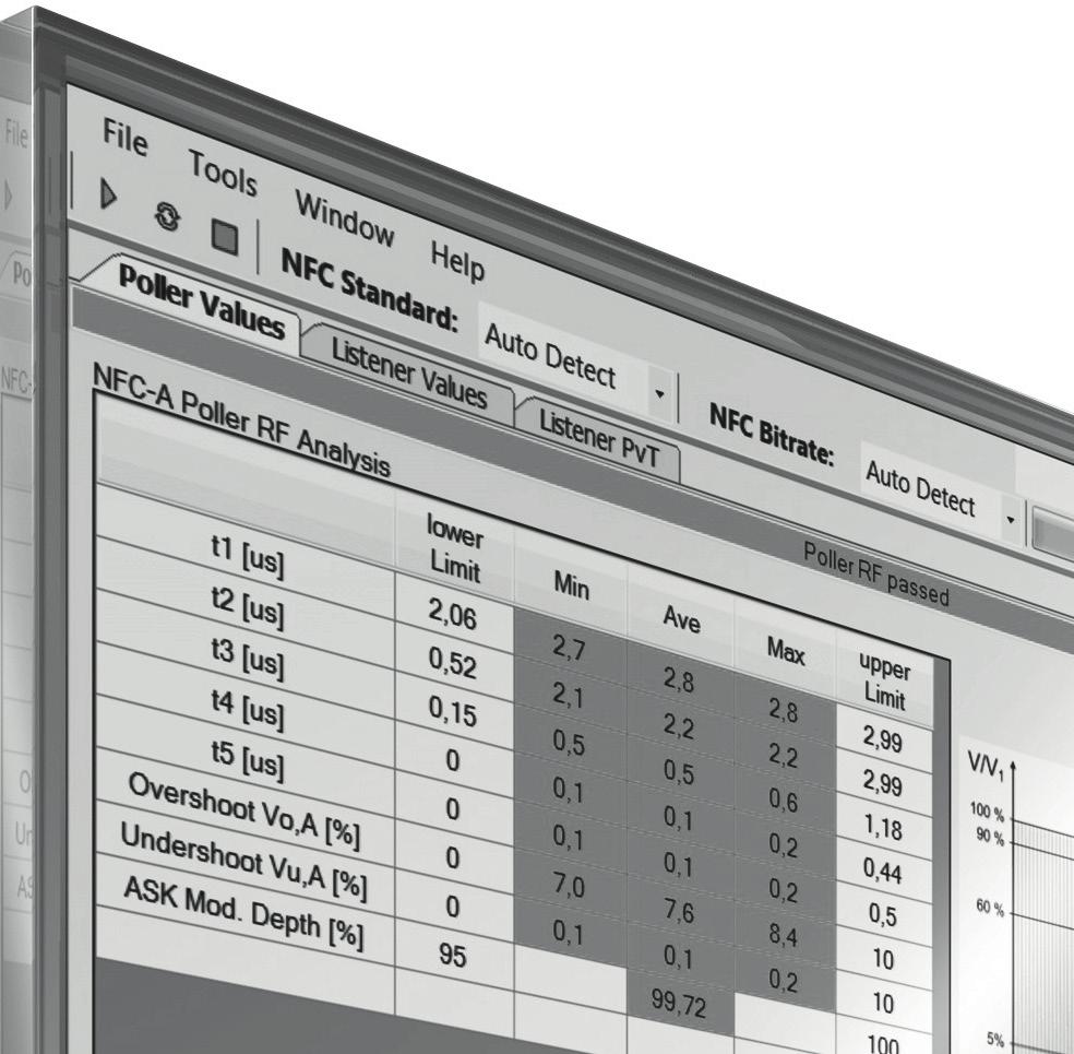
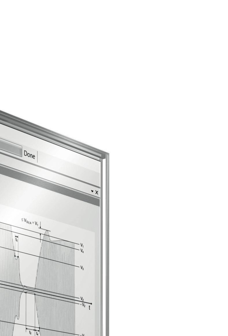
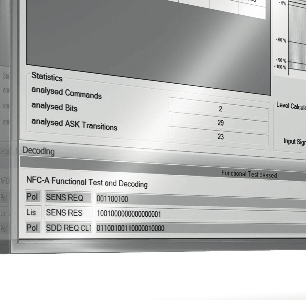
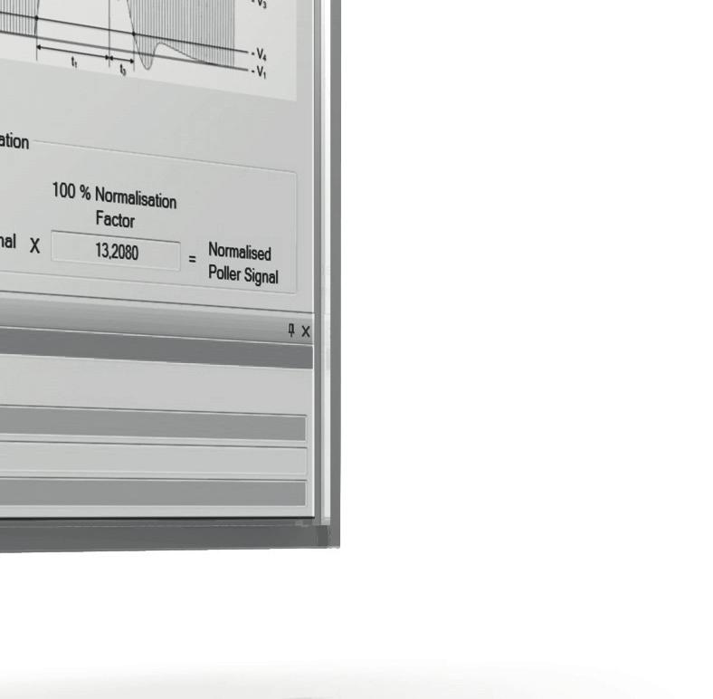
4 Specifications Minimum system requirements for R&S FS-K112PC software The R&S FS-K112PC software is compatible with the R&S FSV/FSL/ZVL/FSW signal and spectrum analyzers and the R&S RTO digital oscilloscope. Running on a PC Operating system Windows XP Professional + Service Pack 2, Windows 7 Free hard disk space 50 Mbyte Free RAM 512 Mbyte Graphics resolution pixel Measuring instrument connection IEC/IEEE bus or LAN connection, VISA driver Measurement parameters Input Supported NFC modulations Supported NFC bitrates NFC reference poller used for listener tests Peak to RMS factor RF NFC-A, NFC-B, NFC-F 106 kbit/s, 212 kbit/s, 424 kbit/s poller 0, poller 3, poller 6 Result display General results Result overview Analyzed standard Analyzed bitrate Poller RF state Listener RF state Functional test state Number of detected poller signals (NFC-A, NFC-B and NFC-F) Decoding Detected poller commands Detected listener commands NFC-A specific results Poller values Unit t 1 µs t 2 µs t 3 µs t 4 µs t 5 µs Overshoot V O, A % Amplitude shift keying modulation depth % Listener values Load modulation mv Frame delay time listener (only available if a listener answer has been detected) µs Frame delay time poller µs (only available if the poller answered to the listener s SENS RES command) Offtime t off µs 4 Rohde & Schwarz R&S FS-K112PC NFC Measurement Software
5 NFC-B specific results Poller values Unit Fall time t f, B µs Rise time t r, B µs Overshoot V O,B % Undershoot V U, B % Modulation index m i, B % Listener values Load modulation mv Frame delay time listener (only available if a listener answer has been detected) µs Frame delay time poller µs (only available if the poller answered to the Listener s SENS RES command) Offtime t off µs NFC-F specific results Poller values Unit Fall time t f, F µs Rise time t r, F µs Overshoot V O, F % Undershoot V U, F % Modulation index m i, F % Listener values Load modulation mv Frame delay time listener (only available if a listener answer has been detected) µs Frame delay time poller µs (only available if the poller answered to the listener s SENS RES command) Offtime t off µs Rohde & Schwarz R&S FS-K112PC NFC Measurement Software 5
6 R&S FSL/ZVL/FSV/FSW Frequency Center frequency range 13.0 MHz to 14.0 MHz Level Level range RF input 50 dbm to +30 dbm Signal acquisition Capture length R&S FSL/ZVL 0.05 ms to 25 ms R&S FSV/FSW 0.05 ms to 100 ms Sample rate 5 MHz to 20 MHz Trigger modes RF input free run, external, IF power Coupling 50 Ω R&S RTO input source Frequency Center frequency range 13.0 MHz to 14.0 MHz Level Level range RF input 50 dbm to +30 dbm Signal acquisition Capture length 0.05 ms to 100 ms Sample rate 5 MHz to 20 MHz Trigger modes RF input free run, external, poller SENS REQ trigger for NFC-A, NFC-B, NFC-F212 and NFC-F424 Input channel channel 1, channel 2, channel 3, channel 4 Coupling 50 Ω or 1000 Ω 6 Rohde & Schwarz R&S FS-K112PC NFC Measurement Software
7 R&S FSV/FSL/FSW measurement uncertainty (nominal) The measurement uncertainty has been measured by connecting the RF output of a vector signal generator directly to the RF input of the R&S FSx. The signal generator has been configured to use a carrier frequency of MHz and an output level of 10 dbm. The measurements have been triggered by using an external trigger signal which was supplied by the marker output of the generator. A sample rate of 20 MHz has been used for the measurements. NFC-A specific parameters t 1 µs < 0.09 < 2/f carrier 0.14 for f carrier = MHz t 2 µs < 0.09 < 2/f carrier 0.14 for f carrier = MHz t 3 µs < 0.03 < 2/f carrier 0.14 for f carrier = MHz t 4 µs < 0.03 < 2/f carrier 0.14 for f carrier = MHz V O, A % < 0.5 < 0.5 NFC-B specific parameters t r, B µs < 0.09 < 2/f carrier 0.14 for f carrier = MHz t f, B µs < 0.09 < 2/f carrier 0.14 for f carrier = MHz V O, B % < 0.5 < 0.5 V U, B % < 0.5 < 0.5 m i, B % < 0.5 < 0.5 valid for modulation NFC-F 212kB specific parameters t r, F µs < 0.13 < 2/f carrier 0.14 for f carrier = MHz t f, F µs < 0.13 < 2/f carrier 0.14 for f carrier = MHz V O, F % < 0.5 < 0.5 V U, F % < 0.5 < 0.5 m i, F % < 0.5 < 0.5 valid for modulation NFC-F 424kB specific parameters t r, F µs < 0.13 < 2/f carrier 0.14 for f carrier = MHz t f, F µs < 0.13 < 2/f carrier 0.14 for f carrier = MHz V O, F % < 0.5 < 0.5 V U, F % < 0.5 < 0.5 m i, F % < 0.5 < 0.5 valid for modulation Rohde & Schwarz R&S FS-K112PC NFC Measurement Software 7
8 R&S ZVL measurement uncertainty (nominal) The measurement uncertainty has been measured by connecting the RF output of a vector signal generator directly to the RF input of the R&S ZVL. The signal generator has been configured to use a carrier frequency of MHz and an output level of 10 dbm. The measurements have been triggered by using an external trigger signal which was supplied by the marker output of the generator. For the R&S ZVL measurements a sampling rate of 16.5 MHz has been used. NFC-A specific parameters t 1 µs < 0.09 < 2/f carrier 0.14 for f carrier = MHz t 2 µs < 0.09 < 2/f carrier 0.14 for f carrier = MHz t 3 µs < 0.03 < 2/f carrier 0.14 for f carrier = MHz t 4 µs < 0.03 < 2/f carrier 0.14 for f carrier = MHz V O, A % < 0.5 < 0.5 NFC-B specific parameters t r, B µs < 0.09 < 2/f carrier 0.14 for f carrier = MHz t f, B µs < 0.09 < 2/f carrier 0.14 for f carrier = MHz V O, B % < 0.5 < 0.5 V U, B % < 0.5 < 0.5 m i, B % < 1.4 < 0.5 valid for modulation NFC-F 212kB specific parameters t r, F µs < 0.13 < 2/f carrier 0.14 for f carrier = MHz t f, F µs < 0.13 < 2/f carrier 0.14 for f carrier = MHz V O, F % < 0.5 < 0.5 V U, F % < 0.5 < 0.5 m i, F % < 1.4 < 0.5 valid for modulation NFC-F 424kB specific parameters t r, F µs < 0.13 < 2/f carrier 0.14 for f carrier = MHz t f, F µs < 0.13 < 2/f carrier 0.14 for f carrier = MHz V O, F % < 0.5 < 0.5 V U, F % < 0.5 < 0.5 m i, F % < 1.4 < 0.5 valid for modulation 8 Rohde & Schwarz R&S FS-K112PC NFC Measurement Software
9 R&S RTO measurement uncertainty (nominal) The measurement uncertainty has been measured by connecting the RF output of a vector signal generator directly to the CH1 input of the R&S RTO. The signal generator has been configured to use a carrier frequency of MHz and an output level of 10 dbm. The measurements have been triggered by using an external trigger signal which was supplied by the marker output of the generator. A sample rate of 20 MHz has been used for the measurements. NFC-A specific parameters t 1 µs < 0.09 < 2/f carrier 0.14 for f carrier = MHz t 2 µs < 0.09 < 2/f carrier 0.14 for f carrier = MHz t 3 µs < 0.03 < 2/f carrier 0.14 for f carrier = MHz t 4 µs < 0.03 < 2/f carrier 0.14 for f carrier = MHz V O, A % < 0.5 < 0.5 NFC-B specific parameters t r, B µs < 0.09 < 2/f carrier 0.14 for f carrier = MHz t f, B µs < 0.09 < 2/f carrier 0.14 for f carrier = MHz V O, B % < 0.5 < 0.5 V U, B % < 0.5 < 0.5 m i, B % < 0.5 < 0.5 valid for modulation NFC-F 212kB specific parameters t r, F µs < 0.09 < 2/f carrier 0.14 for f carrier = MHz t f, F µs < 0.09 < 2/f carrier 0.14 for f carrier = MHz V O, F % < 0.5 < 0.5 V U, F % < 0.5 < 0.5 m i, F % < 0.5 < 0.5 valid for modulation NFC-F 424kB specific parameters t r, F µs < 0.09 < 2/f carrier 0.14 for f carrier = MHz t f, F µs < 0.09 < 2/f carrier 0.14 for f carrier = MHz V O, F % < 0.5 < 0.5 V U, F % < 0.5 < 0.5 m i, F % < 0.5 < 0.5 valid for modulation Rohde & Schwarz R&S FS-K112PC NFC Measurement Software 9
10 Ordering information Designation Type Order No. NFC Measurement Software R&S FS-K112PC License Dongle R&S FSPC Signal and Spectrum Analyzer R&S FSV Signal and Spectrum Analyzer R&S FSW K08 Vector Network Analyzer R&S ZVL Spectrum Analyzer R&S FSL Kxx Digital Oscilloscope R&S RTO xx with R&S RTO-K11 option An R&S FSPC license dongle is necessary to run the R&S FS-K112PC NFC measurement software. Existing license dongles can be used. References [1] NFC Analogue Specification Technical Specification, NFC Forum TM, Analog1.0, NFC Forum-TS-Analog-v1.0, [2] Test Cases for NFC RF Analogue Specification NFC Forum TM, ANALOGUE_TC , NFC Forum_TestCases for Analogue, , CONFIDENTIAL DRAFT. For product brochure, see PD and 10 Rohde & Schwarz R&S FS-K112PC NFC Measurement Software
11 Rohde & Schwarz R&S FS-K112PC NFC Measurement Software 11
12 Service that adds value Worldwide Local and personalized Customized and flexible Uncompromising quality Long-term dependability About Rohde & Schwarz The Rohde & Schwarz electronics group is a leading supplier of solutions in the fields of test and measurement, broadcasting, secure communications, and radiomonitor ing and radiolocation. Founded more than 80 years ago, this independent global company has an extensive sales network and is present in more than 70 countries. The company is headquartered in Munich, Germany. Sustainable product design Environmental compatibility and eco-footprint Energy efficiency and low emissions Longevity and optimized total cost of ownership Certified Quality Management ISO 9001 Certified Environmental Management ISO Rohde & Schwarz GmbH & Co. KG R&S is a registered trademark of Rohde & Schwarz GmbH & Co. KG Trade names are trademarks of the owners PD PD Version October 2014 (as) R&S FS-K112PC NFC Measurement Software Data without tolerance limits is not binding Subject to change Rohde & Schwarz GmbH & Co. KG Munich, Germany PD PDP 1 en Regional contact Europe, Africa, Middle East customersupport@rohde-schwarz.com North America TEST RSA ( ) customer.support@rsa.rohde-schwarz.com Latin America customersupport.la@rohde-schwarz.com Asia Pacific customersupport.asia@rohde-schwarz.com China customersupport.china@rohde-schwarz.com FS_K112-PC_dat-sw_ _cover.indd :19:15
Analog Modulation Analysis (AM/FM/φM) Specifications
 Specifications") Analog Modulation Analysis (AM/FM/φM) Specifications R&S FSW-K7 R&S ESW-K7 R&S FSWP-K7 R&S FSV-K7 R&S FSL-K7 R&S FPS-K7 R&S FPL1-K7 R&S VSE-K7 Data Sheet Version 06.00 CONTENTS Definitions... 3 Specifications...
Analog Modulation Analysis (AM/FM/φM) Specifications R&S FSW-K7 R&S ESW-K7 R&S FSWP-K7 R&S FSV-K7 R&S FSL-K7 R&S FPS-K7 R&S FPL1-K7 R&S VSE-K7 Data Sheet Version 06.00 CONTENTS Definitions... 3 Specifications...
R&S RSC Step Attenuator Specifications
 R&S RSC Step Attenuator Specifications Data Sheet Version 05.00 CONTENTS Definitions... 3 Specifications... 4 Step attenuator, 139 db, 1 db steps, DC to 6 GHz (models.03 and.13)... 4 Step attenuator, 139.9
R&S ZN-Z5x Calibration Units Specifications. Data Sheet V03.00
 R&S ZN-Z5x Calibration Units Specifications Data Sheet V03.00 CONTENTS Definitions... 4 Specifications... 6 Model description R&S ZN-Z5x... 6 Model description R&S ZN-Z15x... 7 Input power limits... 7
R&S ZN-Zxxx Calibration Units Specifications. Data Sheet V04.00
 R&S ZN-Zxxx Calibration Units Specifications Data Sheet V04.00 Version 03.00, January 2019 CONTENTS Definitions... 4 Specifications... 6 Model description R&S ZN-Z5x... 6 Model description R&S ZN-Z15x...
R&S ZV-Z3xx T-Checker Specifications
 ZV-Z3xx_dat-sw_en_3607-0575-22_cover.indd 1 Data Sheet 01.00 Test & Measurement R&S ZV-Z3xx T-Checker Specifications 17.06.2014 15:14:20 CONTENTS Definitions... 3 Specifications... 4 Measurement range...
Noise Figure Measurement Applications Specifications
 Noise Figure Measurement Applications Specifications R&S FSW-K30 R&S FSWP-K30 R&S FPS-K30 R&S FSV-K30 R&S FPL1-K30 Data Sheet Version 02.02 CONTENTS Definitions... 3 Specifications... 4 Frequency... 4
R&S ZV-Z135 Calibration Kit Specifications
 R&S ZV-Z135 Calibration Kit Specifications Test & Measurement Data Sheet 01.01 CONTENTS Definitions... 3 Specifications... 4 Mechanical data... 4 Electrical data of R&S ZV-Z135 (3.5 mm, female)... 4 Electrical
R&S ZVT Vector Network Analyzer Specifications
 ZVT_dat-sw_en_0758-065-22_v0900_cover.indd Data Sheet 09.00 Test & Measurement R&S ZVT Vector Network Analyzer Specifications 06.03.205 5:50:4 CONTENTS Definitions... 3 Specifications... 4 Measurement
R&S ZNBT8 Vector Network Analyzer Specifications
 E stablished 1981 Advanced Test Equipment Rentals www.atecorp.com 800-404-ATEC (2832) ZNBT8_dat-sw_en_3606-9727-22_v0200_cover.indd 1 Data Sheet 02.00 Test & Measurement R&S ZNBT8 Vector Network Analyzer
R&S ZNC Vector Network Analyzer Specifications
 ZNC3_dat-sw_en_5214-5610-22_v0300_cover.indd 1 Data Sheet 03.00 Test & Measurement R&S ZNC Vector Network Analyzer Specifications 04.09.2012 13:39:47 CONTENTS Definitions... 3 Measurement range... 4 Measurement
R&S ZVT Vector Network Analyzer Specifications
 R&S ZVT Vector Network Analyzer Specifications Test & Measurement Data Sheet 08.00 CONTENTS Definitions... 3 Specifications... 4 Measurement range...4 Measurement speed...5 Measurement accuracy...6 Effective
R&S ZNB Vector Network Analyzer Specifications
 Umschlag_ZNB4-8_dat-sw_en_5214-5384-22.indd 1 Data Sheet 02.00 Test & Measurement R&S ZNB Vector Network Analyzer Specifications 07.11.2011 10:03:35 CONTENTS Definitions... 3 Measurement range... 4 Measurement
R&S ZV-Z5x Calibration Units Specifications
 R&S ZV-Z5x Calibration Units Specifications Test & Measurement Data Sheet 10.00 Specifications apply under the following conditions: Sufficient warm-up time (approx. 15 minutes) at ambient temperature,
R&S EB500 Monitoring Receiver Specifications
 Radiomonitoring & Radiolocation Data Sheet 01.02 R&S EB500 Monitoring Receiver Specifications CONTENTS Definitions... 3 Specifications... 4 Frequency...4 Linearity...4 Interference rejection...4 Noise
R&S ZVA-Zxx Millimeter-Wave Converters Network analysis up to 500 GHz
 ZVA-Zxx_bro_en_5214-2033-12.indd 1 Product Brochure 06.02 Test & Measurement R&S ZVA-Zxx Millimeter-Wave Converters Network analysis up to 500 GHz 28.10.2014 21:05:04 R&S ZVA-Zxx Millimeter-Wave Converters
R&S FSC Spectrum Analyzer Specifications
 R&S FSC Spectrum Analyzer Specifications year Data Sheet Version 03.00 CONTENTS Base unit... 3 Frequency... 3 Sweep time... 3 Bandwidths... 3 Level... 4 Trigger functions... 5 Tracking generator (model.13/.16
Attenuators and Matching Pads, Terminations 75 mw to 1000 W, DC to 18 GHz
 Product Brochure Version 8. Attenuators and Matching Pads, Terminations 75 mw to W, DC to 8 GHz Attenuators_dat-bunt_en_758-96_3_v8.indd 3.3.7 7:33:39 Attenuators As a rule, the reflection coefficient
R&S ZVL Vector Network Analyzer Specifications
 R&S ZVL Vector Network Analyzer Specifications Data Sheet Version 10.00 CONTENTS Definitions... 3 Specifications... 4 Measurement range... 4 Measurement speed... 4 Measurement accuracy... 5 Effective system
Guide Version Five techniques for fast, accurate power integrity measurements
 Guide Version 01.00 Five techniques for fast, accurate power integrity measurements Rail voltages are getting smaller, and tolerances are decreasing. As a result, making accurate power rail measurements
R&S ZV-Z5x Calibration Units Specifications
 R&S ZV-Z5x Calibration Units Specifications Test & Measurement Data Sheet 09.01 Specifications apply under the following conditions: Sufficient warm-up time (approx. 15 minutes) at ambient temperature,
Data Sheet Version R&S RT-ZVCxx Multi-Channel Power Probe Specifications
 Data Sheet Version 05.01 R&S RT-ZVCxx Multi-Channel Power Probe Specifications CONTENTS Definitions... 3 Probe characteristics... 4 Voltmeter of the R&S RT-ZVC02/02A/04/04A... 4 Amperemeter of the R&S
R&S NRPM Over-the-Air (OTA) Power Measurement Solution For 5G, WLAN IEEE ad and IEEE ay
 Power Measurement Solution For 5G, WLAN IEEE ad and IEEE ay") year Product Brochure Version 0.00 R&S NRPM Over-the-Air (OTA) Power Measurement Solution For 5G, WLAN IEEE 80.ad and IEEE 80.ay NRPM_bro_en_607-4687-_v000.indd 8.0.09 5:59:08 R&S NRPM Over-the-Air (OTA)
year Product Brochure Version 0.00 R&S NRPM Over-the-Air (OTA) Power Measurement Solution For 5G, WLAN IEEE 80.ad and IEEE 80.ay NRPM_bro_en_607-4687-_v000.indd 8.0.09 5:59:08 R&S NRPM Over-the-Air (OTA)
R&S FPC Spectrum Analyzer Specifications
 R&S FPC Spectrum Analyzer Specifications year Data Sheet Version 04.00 CONTENTS Definitions... 3 Specifications... 4 Frequency... 4 Sweep time... 4 Bandwidth... 4 Level... 5 Trigger functions... 6 Tracking
R&S TS8997 Regulatory Test System for Wireless Devices
 R&S TS8997 Regulatory Test System for Wireless Devices Product Brochure Version 03.01 ETSI EN 300328 V1.8.1/ETSI EN 301893 V1.7.1 compliance tests in the 2.4/5 GHz band TS8997_bro_en_3606-8095-12_v0301.indd
Bring satellites into your lab: GNSS simulators from the T&M expert.
 Bring satellites into your lab: GNSS simulators from the T&M expert. www.rohde-schwarz.com/gnss-solutions Your challenge GNSS receiver tests can only be conclusive when they are performed under realistic
R&S FU129 Antenna Filter Unit Antenna switching, rotator control and signal attenuation, amplification and filtering
 Radiomonitoring & Radiolocation Product Brochure 02.01 R&S FU129 Antenna Filter Unit Antenna switching, rotator control and signal attenuation, amplification and filtering R&S FU129 Antenna Filter Unit
Vector Network Analyzers ZVB
 Specifications Version 05.00 Vector Network Analyzers ZVB September 2005 Specifications MEASUREMENT RANGE...3 MEASUREMENT SPEED...5 MEASUREMENT ACCURACY...6 EFFECTIVE SYSTEM DATA...8 TEST PORT OUTPUT...8
R&S CBT/R&S CBT32 Bluetooth Tester Specifications
 Established 1981 Advanced Test Equipment Rentals www.atecorp.com 800-404-ATEC (2832) R&S CBT/R&S CBT32 Bluetooth Tester Specifications Test & Measurement Data Sheet 06.00 CONTENTS Unit specifications...
Modulation Accuracy Measurements of DVB-S2 and DVB-S2X Signals Application Note
 Modulation Accuracy Measurements of DVB-S2 and DVB-S2X Signals Application Note Products: ı ı ı ı R&S FSW-K70 R&S FSW-K70M R&S FPS-K70 R&S VSE-K70 This Application Note gives a short overview how signals
R&S CLGD DOCSIS Cable Load Generator Multichannel signal generator for DOCSIS 3.1 downstream and upstream
 CLGD_bro_en_3607-0123-12_v0200.indd 1 Product Brochure 02.00 Broadcast & Media Test & Measurement R&S CLGD DOCSIS Cable Load Generator Multichannel signal generator for downstream and upstream 24.07.2015
R&S TS-EMF EMF Measurement System Easy, frequency-selective measurement of EMF emissions
 TS-EMF_dat_en_0758-2777-12_v0501.indd 1 Product Brochure 05.01 Test & Measurement R&S TS-EMF EMF Measurement System Easy, frequency-selective measurement of EMF emissions 11.04.2016 09:35:59 R&S TS-EMF
R&S SMC100A Signal Generator Specifications
 R&S SMC100A Signal Generator Specifications Test & Measurement Data Sheet 01.00 CONTENTS Key features... 3 Specifications... 4 RF characteristics...4 Frequency...4 Frequency sweep...4 Reference frequency...4
R&S FSx-K91/-K91n, R&S FSW/FSQ-K91ac WLAN Application Firmware WLAN TX measurements with Rohde & Schwarz analyzers
 Test & Measurement Product Brochure 03.00 R&S FSx-K91/-K91n, R&S FSW/FSQ-K91ac WLAN Application Firmware WLAN TX measurements with Rohde & Schwarz analyzers R&S FSx-K91/-K91n R&S FSW-K91ac/ R&S FSQ-K91ac
R&S FSWP Phase Noise Analyzer Specifications
 FSWP_dat-sw_en_3607-2090-22_v0300_cover.indd 1 Data Sheet 03.00 Test & Measurement R&S FSWP Phase Noise Analyzer Specifications 19.05.2016 10:13:04 CONTENTS Definitions... 3 Specifications... 4 Frequency...
Power Added Efficiency Measurement with R&S ZNB/ R&S ZVA
 Power Added Efficiency Measurement with R&S ZNB/ R&S ZVA Application Note Products: R&S ZNB R&S ZVA Power Added Efficiency (PAE) is a key parameter for the characterization of an amplifier. This application
R&S ZNA Vector Network Analyzer Specifications
 R&S ZNA Vector Network Analyzer Specifications Data Sheet Version 01.02 year ZNA_dat-sw_en_5215-4652-22_v0102_cover.indd 1 07.01.2019 12:23:03 Version 01.02 January 2019 CONTENTS Definitions... 3 Measurement
R&S FSWP Phase Noise Analyzer Specifications
 R&S FSWP Phase Noise Analyzer Specifications Test & Measurement Data Sheet 02.01 CONTENTS Definitions... 3 Specifications... 4 Frequency... 4 Phase noise measurements... 4 Phase noise sensitivity with
R&S ESCI/ESCI7 EMI Test Receiver Specifications
 R&S ESCI/ESCI7 EMI Test Receiver Specifications Test & Measurement Data Sheet 03.00 Specifications Specifications apply under the following conditions: 15 minutes warm-up time at ambient temperature, specified
R&S NRP-Zxx Power Sensors Specifications
 R&S NRP-Zxx Power Sensors Specifications year Data Sheet Version 11.00 CONTENTS Definitions... 3 Overview of the R&S NRP-Zxx power sensors... 4 Specifications in brief of the R&S NRP-Zxx power sensors...
R&S ESRP EMI Test Receiver Specifications
 R&S ESRP EMI Test Receiver Specifications Test & Measurement Data Sheet 01.01 CONTENTS Definitions... 3 Specifications... 4 Frequency... 4 Preselection and preamplifier (R&S ESRP-B2 option)... 6 RF preamplifier
R&S NRP Power Meter Family Specifications
 R&S NRP Power Meter Family Specifications year Data Sheet Version 06.00 CONTENTS Definitions... 3 Overview of the R&S NRP power sensors... 4 Specifications in brief of the R&S NRP power sensors... 5 Multipath
Measurement Setup for Phase Noise Test at Frequencies above 50 GHz Application Note
 Measurement Setup for Phase Noise Test at Frequencies above 50 GHz Application Note Products: R&S FSWP With recent enhancements in semiconductor technology the microwave frequency range beyond 50 GHz becomes
Noise Figure Measurement in the 60 GHz Range Application Note
 Noise Figure Measurement in the 60 GHz Range Application Note Products: R&S FSU67 Noisecom Noise Figure Test Set - NC5115-60G - NC5115-60GT This application note describes how noise figure and gain of
LabWindows/CVI, VXIpnp driver history for the R&S Radio Tester
 Miloslav Macko May 11, 2017 LabWindows/CVI, VXIpnp driver history for the R&S Radio Tester Products: R&S CMA180 Driver history for LabWindows/CVI and VXIplug&play Instrument Driver for C/C++, C#, VEE,
R&S NRP USB and LAN Power Sensors Specifications
 NRP-Family_dat-sw_en_3607-0852-22_v0200_Cover.indd 1 Data Sheet 02.00 Test & Measurement R&S NRP USB and LAN Power Sensors Specifications 01.12.2015 13:55:03 CONTENTS Definitions... 3 Overview of the R&S
R&S TSMW, TSME, TSMA LTE Downlink Allocation Analysis Application Note
 R&S TSMW, TSME, TSMA LTE Downlink Allocation Analysis Application Note Products: ı ı ı ı R&S TSMW R&S TSME R&S TSMA R&S ROMES4 Application Note Jordan Schilbach 12.2016 04.00 Table of Contents 1Introduction
Spectrum Analyzer FSL
 Specifications Version 02.00 Spectrum Analyzer FSL August 2005 Specifications Specifications Specifications apply under the following conditions: 15 minutes warm-up time at ambient temperature, specified
R&S FSH4/8 Spectrum Analyzer Specifications
 R&S FSH4/8 Spectrum Analyzer Specifications Test & Measurement Data Sheet 02.00 CONTENTS Specifications... 3 Frequency...3 Sweep time...3 Bandwidths...4 Level...4 Trigger functions...5 Inputs and outputs...6
R&S ENV216 Two-Line V-Network For disturbance voltage measurements on single-phase EUTs
 R&S ENV216 Two-Line V-Network For disturbance voltage measurements on single-phase EUTs Test & Measurement Data Sheet 03.00 R&S ENV216 Two-Line V-Network At a glance The R&S ENV216 two-line V-network meets
Bring satellites into your lab
 Bring satellites into your lab GNSS simulators from the T&M expert 5215.5042.32 02.01 PDP 1 en www.rohde-schwarz.com/gnss-solutions GNSS-Simulators--------Bring-satellites_fly_5215-5042-32_v0201.indd 7
Receiver requirements for a TDOA-based radiolocation system
 Receiver_requirements_app-bro_en_3606-9162-92.indd 1 Receiver requirements for a TDOA-based radiolocation system Radiomonitoring & Radiolocation Application Brochure 01.00 Receiver requirements for a TDOA-based
Near Field Communication (NFC) Technology and Measurements White Paper
 Technology and Measurements White Paper") Near Field Communication (NFC) Technology and Measurements White Paper Near Field Communication (NFC) is a new short-range, standards-based wireless connectivity technology, that uses magnetic field induction
Near Field Communication (NFC) Technology and Measurements White Paper Near Field Communication (NFC) is a new short-range, standards-based wireless connectivity technology, that uses magnetic field induction
R&S TS-PSAM Analog Source and Measurement Module Scanning multimeter and data acquisition unit
 TS-PSAM_bro_en_0758-0580-12.indd 1 Product Brochure 03.00 Test & Measurement R&S TS-PSAM Analog Source and Measurement Module Scanning multimeter and data acquisition unit 12.12.2013 15:34:44 R&S TS-PSAM
Signal Generator SMA 100A
 Specifications Version 01.01 Signal Generator SMA 100A April 2006 Specifications CONTENTS CONTENTS... 2 KEY FEATURES... 3 SPECIFICATIONS... 4 RF CHARACTERISTICS... 4 Frequency... 4 Frequency sweep... 4
R&S CMU-Z10/-Z11 Antenna Coupler/ RF Shielding Cover Simple interference-free testing of all mobiles
 R&S CMU-Z1/-Z11 Antenna Coupler/ RF Shielding Cover Simple interference-free testing of all mobiles Test & Measurement Data Sheet 3. R&S CMU-Z1 /-Z11/-Z1/-Z13/-Z1 At a glance Anyone engaged in mobile phone
Evolution of the Modern Receiver in a Crowded Spectrum Environment White Paper
 Evolution of the Modern Receiver in a Crowded Spectrum Environment White Paper The International Telecommunications Union Radiocommunications working group (ITU-R) outlines recommendations for the regulations
Group Delay measurements with Signal and Spectrum Analyzers Application Note
 Group Delay measurements with Signal and Spectrum Analyzers Application Note Products: ı ı R&S FSW R&S FSW-K17 Phase distortions in a transmission channel are determined using group delay measurements,
R&S ESR EMI Test Receiver Specifications
 ESR_dat-sw_en_3606-7201-22_cover.indd 1 Data Sheet 02.00 Test & Measurement R&S ESR EMI Test Receiver Specifications 30.07.2013 16:02:30 CONTENTS Definitions... 3 Specifications... 4 Frequency... 4 Preselection
Application Firmware for Phase Noise Measurements FS-K40
 Data sheet Version 01.00 Application Firmware for Phase Noise Measurements FS-K40 June 2005 Phase noise measurements with Analyzers FSP/FSU/FSQ/FSMR Editable sweep settings: Measurement range Resolution
R&S FPL1000 Spectrum Analyzer Experience high performance wherever you take it
 R&S FPL1000 Spectrum Analyzer Experience high performance wherever you take it Product Brochure Version 02.00 year FPL1000_bro_en_5214-6974-12_v0200.indd 1 13.09.2017 19:43:11 R&S FPL1000 Spectrum Analyzer
Trends in connected cars at a glance V2X V2V, V2I, V2P, C-V2X, 3GPP LTE-V2X, DSRC, WAVE, ITS-G5, IEEE p
 Trends in connected cars at a glance V2X V2V, V2I, V2P, C-V2X, 3GPP LTE-V2X, DSRC, WAVE, ITS-G5, IEEE 802.11p What s coming Your challenge... We are on the verge of a new generation of mobility. Development
R&S EM510 HF Digital Wideband Receiver Efficient and versatile solution for radiomonitoring
 EM510_bro_en_5213-7731-32_v0200.indd 1 Product Brochure 02.00 Radiomonitoring & Radiolocation R&S EM510 HF Digital Wideband Receiver Efficient and versatile solution for radiomonitoring 27.05.2015 16:01:58
Wideband mm-wave Signal Generation and Analysis
 Application Note R Minihold, R. Wagner 7.2017 1MA257_3e Wideband mm-wave Signal Generation and Analysis Application Note Products: R&S SMW200A R&S FSW R&S SMB100A R&S FSW-B2000 R&S SMF100A R&S FSW-B21
R&S ESRP EMI Test Receiver Specifications
 R&S ESRP EMI Test Receiver Specifications Test & Measurement Data Sheet 03.00 CONTENTS Definitions... 3 Specifications... 4 Frequency... 4 Preselection and preamplifier (R&S ESRP-B2 option)... 6 RF preamplifier
R&S FSV Signal Analyzer Specifications
 R&S FSV Signal Analyzer Specifications Test & Measurement Data Sheet 01.00 CONTENTS Specifications... 3 Frequency...3 Sweep time...4 Resolution bandwidths...4 Level...5 Measurement speed...7 Trigger functions...8
R&S FSV Signal and Spectrum Analyzer Specifications
 R&S FSV Signal and Spectrum Analyzer Specifications Test & Measurement Data Sheet 02.02 CONTENTS Specifications... 3 Frequency...3 Sweep time...4 Resolution bandwidths...4 Level...5 Measurement speed...8
R&S SMB100N SIGNAL GENERATOR
 R&S SMB100N SIGNAL GENERATOR PERFORMANCE SPECIFICATIONS VERSION 02.00, SEPTEMBER 2009 CONTENTS Specifications...3 Definitions... 3 RF performance... 4 Frequency... 4 Frequency sweep... 4 Reference frequency...
R&S UMS175 Compact Radiomonitoring System High performance for outdoor deployment
 UMS175_bro_en_3607-1488-12_v0201.indd 1 Product Brochure 02.01 Radiomonitoring & Radiolocation R&S UMS175 Compact Radiomonitoring System High performance for outdoor deployment 11.02.2016 09:50:15 R&S
Radio Network Analyzer TSMU/TSMU-H
 Flyer Radio Network Analyzer TSMU/TSMU-H Universal platform for coverage measurements UMTS PN scanning (bands I to VI) with BCH (SIB) decoder ( TSMU) GSM network scanning (bands 850, 900 public/extended/rail,
Signal Generator SMA100A
 Product brochure Version 02.01 Signal Generator SMA100A November 2006 The new standard of excellence in the analog signal generator class Excellent signal quality Ideal for use in production All-purpose
GSM/EDGE Application Firmware R&S FS-K5 for R&S FSP and R&S FSU
 GSM/EDGE Application Firmware R&S FS-K5 for R&S FSP and R&S FSU The solution for easy and fast GSM and EDGE measurements GSM/EDGE push-button measurements Fast modulation spectrum routine Easy to use Accurate
R&S ZVH Cable and Antenna Analyzer Specifications
 ZVH_dat-sw_en_5214-4588-22_cover.indd 1 Data Sheet 06.00 Test & Measurement R&S ZVH Cable and Antenna Analyzer Specifications 26.03.2015 15:40:31 CONTENTS Definitions... 3 Specifications... 4 Frequency...
R&S DF-ATC-S ATC DF System Solution Accurate and reliable direction finding for civil and military air traffic control
 Product Brochure Version 0.00 R&S DF-ATC-S ATC DF System Solution Accurate and reliable direction finding for civil and military air traffic control DF-ATC-S_bro_en_525-0792-2_v000.indd 20.02.208 :9:40
Spectrum Analyzer R&S FS300
 Spectrum Analyzer R&S FS300 9 khz to 3 GHz The new product family from Rohde & Schwarz Professional test equipment for laboratory, service and production The R&S FS300 is a highly accurate spectrum analyzer
R&S NRT Power Reflection Meter Family R&S NRT2 and R&S NRT-Zxx
 R&S NRT Power Reflection Meter Family R&S NRT2 and R&S NRT-Zxx Product Brochure Version 01.00 year NRT_bro_en_5215-0986-12_v0100.indd 1 07.08.2017 10:45:57 R&S NRT Power Reflection Meter Family At a glance
R&S SMA100A Signal Generator The new standard of excellence in the analog signal generator class
 SMA100A_bro_en_5213-6412-12.indd 1 Product Brochure 06.01 Test & Measurement R&S SMA100A Signal Generator The new standard of excellence in the analog signal generator class 04.06.2013 10:13:49 R&S SMA100A
R&S NRPC Calibration Kits Calibration of power sensors
 R&S NRPC Calibration Kits Calibration of power sensors Product Brochure Version 03.00 year NRPC_bro_en_5214-6297-12_v0300.indd 1 10.04.2018 10:30:29 R&S NRPC Calibration Kits At a glance The five modular
Measuring Receiver FSMR
 Product brochure Version 01.00 02.00 Measuring Receiver FSMR November April 2004 2006 All-in-one solution for the calibration of signal generators and attenuators Frequency range from 20 Hz to 3/26.5/50
R&S MNT100 RF Interference Locator Specifications
 R&S MNT100 RF Interference Locator Specifications Data Sheet Version 02.00 CONTENTS Specifications... 3 RF data... 3 Noise figure, DANL... 3 Phase noise... 3 Sensitivity (demodulation path) with ITU-T
RF Signal Generator SM300
 RF Signal Generator SM300 9 khz to 3 GHz With compliments Helmut Singer Elektronik www.helmut-singer.de info@helmut-singer.de fon +49 241 155 315 fax +49 241 152 066 Feldchen 16-24 D-52070 Aachen Germany
Voltage Sensors URV5-Z
 Data sheet Version 05.00 Voltage Sensors URV5-Z May 2005 Universal voltage measurements from RF to microwaves The voltage sensors of the URV5-Z series are indispensable tools in RF and microwave laboratories,
R&S ZVH Cable and Antenna Analyzer Specifications
 Umschlag_ZVH_dat-sw_v0300.indd 1 Data Sheet 03.00 Test & Measurement R&S ZVH Cable and Antenna Analyzer Specifications 18.05.2011 11:30:50 CONTENTS Definitions... 3 Specifications of the R&S ZVH cable
R&S NRPC Calibration Kits Calibration of power sensors
 R&S NRPC Calibration Kits Calibration of power sensors Test & Measurement Product Brochure 02.00 R&S NRPC Calibration Kits At a glance The four modular R&S NRPC calibration kits are used to calibrate power
R&S OSP Open Switch and Control Platform Specifications
 R&S OSP Open Switch and Control Platform Specifications Data Sheet Version 18.00 CONTENTS Definitions... 4 Introduction... 5 R&S OSP120... 5 R&S OSP130... 5 R&S OSP150... 5 R&S OSP-B200S2... 5 General
MDS-21 Absorbing Clamp, EZ-24 Ferrite Clamp
 Version 06.00 MDS-21 Absorbing Clamp, EZ-24 Ferrite Clamp July 2007 Measurement of disturbance power and screening effectiveness on cables Reproducible measurements of disturbance field strength and disturbance
FMU36 Baseband Signal Analyzer
 Version 01.00 FMU36 Baseband Signal Analyzer January 2007 Specifications Contents SPECIFICATIONS... 3 FREQUENCY... 3 SWEEP... 3 RESOLUTION BANDWIDTHS... 3 LEVEL... 4 DYNAMIC RANGE... 5 PHASE... 5 PROBE
R&S CMW100 Communications Manufacturing Test Set Specifications
 R&S CMW100 Communications Manufacturing Test Set Specifications Data Sheet Version 02.00 CONTENTS Definitions... 6 General technical specifications... 7 RF generator... 8 Modulation source: arbitrary waveform
R&S OSP Open Switch and Control Platform Specifications
 R&S OSP Open Switch and Control Platform Specifications Data Sheet Version 15.00 CONTENTS Definitions... 4 Introduction... 5 R&S OSP120... 5 R&S OSP130... 5 R&S OSP150... 5 R&S OSP-B200S2... 5 General
R&S FSUP Signal Source Analyzer Specifications
 Test & Measurement Data Sheet 06.03 R&S FSUP Signal Source Analyzer Specifications CONTENTS Specifications... 3 All operating modes... 3 Signal source analyzer mode... 3 Phase noise measurement with PLL
R&S ETH Handheld TV Analyzer Specifications
 R&S ETH Handheld TV Analyzer Specifications year Data Sheet Version 11.00 CONTENTS Definitions... 3 Specifications... 4 TV analyzer... 4 Frequency... 4 Level... 4 RF preselection (R&S ETH-K1 option)...
R&S NRP USB and LAN Power Sensors Specifications
 R&S NRP USB and LAN Power Sensors Specifications year Test & Measurement Data Sheet 04.00 CONTENTS Definitions... 3 Overview of the R&S NRP power sensors... 4 Specifications in brief of the R&S NRP power
R&S ZVH Cable and Antenna Analyzer Where mobility counts
 Test & Measurement Product Brochure 01.00 R&S ZVH Cable and Antenna Analyzer Where mobility counts R&S ZVH Cable and Antenna Analyzer At a glance The R&S ZVH cable and antenna analyzer is rugged, handy
ENY81 Coupling Network
 Version 01.00 ENY81 Coupling Network January 2008 For radio disturbance measurements on unshielded, symmetrical telecommunications ports Eight-wire network Radio disturbance measurements in line with CISPR
R&S ESR EMI Test Receiver Specifications
 R&S ESR EMI Test Receiver Specifications Data Sheet Version 06.00 CONTENTS Definitions... 3 Specifications... 4 Frequency... 4 Preselection and preamplifier... 6 IF and resolution bandwidths... 7 Level...
SMA100A Signal Generator
 Version 02.02 SMA100A Signal Generator August 2007 Data sheet CONTENTS KEY FEATURES...3 SPECIFICATIONS...4 RF CHARACTERISTICS...4 Frequency...4 Frequency sweep...4 Reference frequency...4 Level...5 Level
R&S MNT100 RF Interference Locator
 R&S MNT100 RF Interference Locator Product Brochure Version 02.00 Radiolocation in mobile networks From the experts MNT100_bro_en_5215-3762-12_v0200.indd 1 21.01.2019 09:37:04 R&S MNT100 RF Interference
Provided by R&S FSH4/FSH8 Spectrum Analyzer Specifications
 Provided by www.aaatesters.com R&S FSH4/FSH8 Spectrum Analyzer Specifications Test & Measurement Data Sheet 04.00 CONTENTS Specifications...3 Frequency...3 Sweep time...3 Bandwidths...4 Level...4 Trigger
Automated Measurements of 77 GHz FMCW Radar Signals
 Application Note Dr. Steffen Heuel 4.2014-1EF88_0e Automated Measurements of 77 GHz FMCW Radar Signals Application Note Products: R&S FSW R&S FS-Z90 Frequency Modulated Continuous Wave (FMCW) radar signals
R&S CMW100 Communications Manufacturing Test Set Specifications
 R&S CMW100 Communications Manufacturing Test Set Specifications R&S CMW100 model.k06 Data Sheet Version 03.00 CONTENTS Definitions... 4 General technical specifications... 5 RF generator... 6 RF analyzer...
DSA700 Series Spectrum Analyzer
 DSA700 Series Spectrum Analyzer Product Features: All-Digital IF Technology Frequency Range from 100 khz up to 1 GHz Min. -155 dbm Displayed Average Noise Level (Typ.) Min.