FLORIDA INTERNATIONAL UNIVERSITY ELECTRICAL & COMPUTER ENGINEERING LAB INSTRUMENTS USER MANUAL
|
|
|
- Johnathan Burns
- 5 years ago
- Views:
Transcription

1 FLORIDA INTERNATIONAL UNIVERSITY ELECTRICAL & COMPUTER ENGINEERING LAB INSTRUMENTS USER MANUAL
2 Contents 1. Digital Multimeter-HP34401A Quick Start... 6 o Introduction... 7 o Resistance Measurement... 9 Two-wire Method. 9 Null Function... 9 Range Selection Min/Max and Average o Resistance Color Code and Power Rating.. 11 o Voltage Measurement.13 o Current Measurement o Frequency Measurement.. 16 o Specifications Programmable Power Supply-HP E3631A 18 o Quick Start.. 18 o Introduction o Basics of Power Supplies: CV, CC and CV/CC o HP E3631A Triple Output DC Power Supply...20 A Simplified View of a Power Supply Constant Voltage Constant Current.. 23 Disabling the Outputs Other Features o Specifications Digital 2 Channel 100 MHz Osciloscope-HP54600B o Quick Start. 25 o Features 26 o Getting Familiar with the Scope Front Panel Controls.. 27 Display Features Helpful Hints 28 Setting Probe Attenuation Factor. 28 o List of Procedures Adjusting The Oscilloscope Display. 29 Vp-p
3 Vrms 29 Frequency Period. 30 Risetime.. 30 Offset...30 Selecting the Trigger Source Setting the Trigger Mode 30 Averaging 31 Measuring Signal Amplitudes. 31 Measuring the Phase Shift between Channels...31 o Taking Measurements (Examples) Peak-Peak Voltage Measurements.. 32 Rise Time...32 Rise Time With Delayed Sweep FFT.. 33 Storing Waveforms. 34 Auto Store Saving to Trace Memory.. 34 o Specifications Function Generator/Arbitrary Wave Generator-HP33120A o Quick Start.. 37 o Introduction o Basics of the Function/Waveform Generator (HP 33120A) Functions and use of HP 33120A a. Front Panel Number Entry 42 b. Selection of Standard Functions. 43 c. Frequency Selection.. 43 d. Amplitude Selection.. 43 e. Offset Selection...44 f. Duty Cycle Selection g. Output of an Arbitrary Waveform. 44 Front Panel Menu 45 a. Selection of the Output Impedance (50 Ohm or High Z) 45 b. Advanced Modification of a Standard Waveform.. 45 Storing Arbitrary Waveforms 47 o Specifications
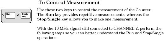
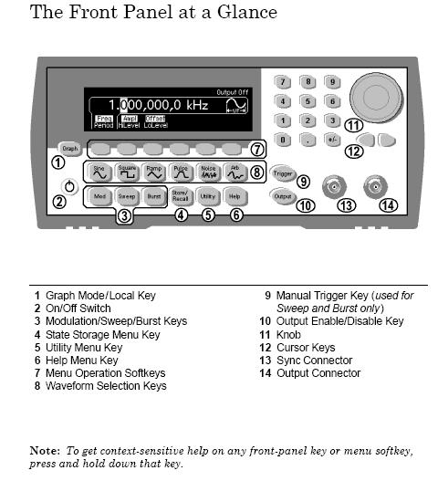
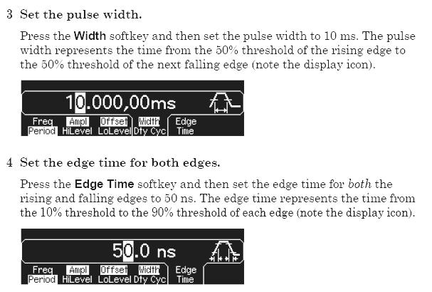
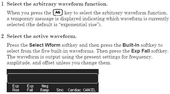
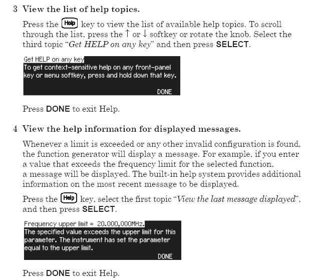
4 5. HP 53131A DC-225MHZ 10 Digit Universal Counter o Quick Start o Key Features.. 50 o The Front Panel at a Glance o The Front Panel Indicators at a Glance. 52 o The Front Panel Menus at a Glance.54 o Making Measurements.. 56 o To Control Measurement Function/Arbitrary Waveform Generator HP33220A 20 MHz 73 o Specification o The Front Panel at a Glance. 74 o The Front Panel Display at a Glance o Front-Panel Number Entry o To Set Output Frequency o To Set Output Amplitude o To Set a DC Offset Voltage o To Set the High-Level and Low-Level Values o To Set DC Volts o To Set the Duty Cycle of a Square Wave o To Configure a Pulse Waveform.. 81 o To View a Waveform Graph o To Output a Stored Arbitrary Waveform o To Use the Built-In Help System. 83 o To Select the Output Termination o To Output a Modulated Waveform o To Output an FSK Waveform o To Output a PWM Waveform o To Output a Frequency Sweep
 which will allow you to check any voltage from 0 to 200V DC at the 200 V terminals, and 0 to 1000V DC at the 1000 V terminals ( Red")
5 1. Digital Multimeter-HP34401A QUICK START Turn ON the unit; the unit will test itself and will show Adds # 22. Also, will set to mv (milivolts) which is the default. DC (Default). The unit will also be set at Auto Range (Automatic Voltage Reading) which will allow you to check any voltage from 0 to 200V DC at the 200 V terminals, and 0 to 1000V DC at the 1000 V terminals ( Red buttons at front panel). Note: For any voltage over 30V, check with the instructor BEFORE YOU ATTEMPT TO MEASURE. To measure AC Voltage, press the AC voltage button and be sure that the leads are now in the correct position for the correct amount of voltage to be measured. Note: See the Lab instructor if any doubt. For DC current, press the blue (shift) button, then V DC Volt button. Before this test, leads must be placed as fallows: Positive lead to the current terminal (Red button outlet) while the ground lead remains at the same position. Note: To measure currents, the meter must be in series with the part of the circuit under test. Never measure current across a circuit component. To measure AC Current, press the blue (shift) button and AC Volt button. Remember, test cables must be placed in correct terminals to measure currents. 5
6 To measure current at any part of your circuit on the board, connect the multimeter in series with the components or wire in that part of your circuit. Do not connect the meter across (in parallel) any component or wire. See your lab instructor for help. NOTE: For any current over 1 Amp, see your Lab Instructor for assistance, BEFORE YOU MEASURE! To check Resistance: First, be absolutely sure that there is NO POWER connected to the resistance under test. It is recommended to place the resistor(s) at an empty part of the Proto Board, not connected to the other part of the circuit, to do the measurement. Leads will be place as if were to measuring voltage, press the Ω from the front panel After the measurement has been made, reconnect the right resistance(s) back into the circuit, and then, reconnect the power. NOTE: Range at the resistance meter s panel is auto, but can be adjusted manually By pressing the arrows (, ) at the front of the unit s panel. See below for more details. Figure 1: Measurement of resistance, voltage and current with a multimeter Introduction One of the most important functions of ECE Lab is to provide an understanding of the functions of instruments. For ECE students, this knowledge is essential to conduct laboratory assignments and develop independent design projects. Currents and voltages are the basic circuit variables of interest. In this Lab we are mainly concerned with accurately measuring resistance, DC voltage and currents using a digital multimeter (DMM). We will use the HP34401A digital multimeter which is a high performance instrument capable of measuring resistance, DC and AC voltage and current, as well as frequency. The HP34401A has a built-in microprocessor, memory and other electronics components that give it numerous features such as built-in math functions, recording and storing up to 512 readings, giving the maximum, minimum and average of the readings. In addition, it 6
7 can be remotely programmed using the SCPI (Standard Commands for Programmable Instruments) language and read by computer via a General Purpose Interface Board (GPIB) port. The use of the instrument for measurement of resistance, current and voltage is in principle very simple. Figure 1 shows the set up for resistance, voltage and current measurements. For resistance measurements, one connects the DMM over the resistor. Notice that for voltage measurements one puts the multimeter in parallel with the circuit element so that one measures the voltage across the element. In case of a current measurement, one must put the DMM in serial with the element in order to measure the current through the element. That involves breaking the circuit in order to insert the multimeter in the circuit loop. 7

8 Resistance measurements with the HP34401 To Measure Resistance Ranges: 100 Ω, 1 kω, 10 kω, 100 kω, 1 M Ω, 10M Ω, 100MΩ Maximum resolution: 100 µ Ω (on 100 ohm range) 4 wire measurement 4 Wires Ω 4W Ω 2W Shift Principle of 2 wire measurement The DMM measures a resistance by applying a known DC voltage over unknown resistance in series with a small resistance R m. It measures the voltage over the resistance R m as shown in Figure 2. The DMM can then calculate the unknown resistance R. 8
9 Figure 2: Two-wire resistance measurement To use the DMM for resistance measurements, connect the resistor to the terminals labeled HI (V Ω)and LO, select the resistance measurement function by pushing the [Ω] button (one of the function keys) on the front panel as shown below in Figure 3. Please notice that the selection keys are annotated in black and blue. To select the function in blue, please press the blue SHIFT key. Figure 3: Function buttons to select resistance, voltage, current or frequency Measurement errors and Null function. If using DMM to measuring the small value of resistor with cables, the resistance of cables may even larger than small resistor. The HP34401A DMM can overcome this problem by using the Null feature. The front panel of the DMM (see Figure 3) has a Null button. To null the wire resistance, short the ends of the test wire and then press the Null button. You can disable the Null function by pushing the button again. CAUTION: To test resistance, the safest way is disconnect all voltage sources before connecting the DMM to the circuit. A large voltage input terminals of the DMM may damage the meter. Range selector The multimeter automatically selects the range using the auto-ranging feature. However, you can 9

10 also manually select a fixed range (e.g. 1KΩ or 1MΩ) using the Auto/Man button on the front panel (under Range/Digits) buttons (Figure 4). The 'down' arrow selects the lower range and the 'up' arrow the higher range. Figure 4: Function, Math, Range, and Menu keys Additional features of the HP34401A: average, max and min value To find the average value, maximum and minimum values of variable test points, HP34401A has built-in features. To enable this feature, push the Min/Max button (one of the Math buttons) on the front panel. The Math annunciator will lit on, and DMM will make short beeps indicating it is taking readings and storing the MAX, MIN, Average value, and the total COUNT. Push the Min/Max button again to stop the readings. To access these stored numbers, just turn the Menu on by pressing the On/Off key (SHIFT <) on the front panel (see Figure 4). Then, use the > or < keys until you are in the MATH (B) menu. You can now go down to the "parameter level" of the selected MIN-MAX menu by pressing the "down" button until you see the desired parameter menu (1:MIN_MAX) displayed. Press "down" button again, you are in the MIN-MAX menu. Please use the > or < buttons to scroll through the menu and read the values. The menu is organized in three levels, as Fig. 5. Figure 5: The front panel menu organization. 10

11 The MIN-MAX feature can be used for resistance measurements as well as for voltage, current, and frequency measurements. The resistance color code and power rating Resistors are usually color coded using color banding as shown in Figure 6. Two digits and a power 10 multiplier determine the resistance value. The color band on the most left is the 1st significant digit, followed by the 2nd digit and the multiplier. The fourth band is usually present as well and indicates the tolerance of the specified resistance. Figure 6: The 5% Resistor Color Code. 11
12 Power rating of resistors In addition to the value and tolerance of a resistor, the power rating is another important characteristic. It tells how much power the resistor can dissipate before being damaged by overheating. Resistors come in different power ratings: 1/8, 1/4, 1/2, 1 and 2 Watts are typical values. Voltage measurement Ranges: 100mV, 1V, 10V, 100V, 1000V (750 Vac) Maximum resolution: 100nV (on 100 mv range) AC technique: true RMS, ac-coupled + AC or DC Voltage _ Principle of measurement A DC voltage is measured by using a voltage amplifier and an analog-to-digital converter as schematically shown in Figure 7. A microprocessor further manipulates the data before displaying the results. Figure 7: Schematic of the DMM as a DC voltage meter. 12
13 To measure a voltage, connect the nodes over which one wants to measure the voltage between the HI and LO input terminals of the DMM (Figure 3). In order to activate the DMM for DC measurements you have to select the DC Voltage function by pushing the DC V button on the front panel (see Figure 3). The Math functions, such as Max/Min and average, can be activated in a similar fashion as was done for the resistance measurements. Also, the range can be selected manually by pushing the Man/Auto key in the Range menu. If you have the probes connected for measuring currents and you try to measure the voltage of low-impedance voltage source (such as power supply), you will blow a fuse in the instrument. In order to avoid this, always remember to check the connection of your probes before making voltage measurement. Errors due to the internal resistance An ideal voltmeter has an infinite input resistance so that it will not draw any current from the circuit under testing. However, in reality, there is always a finite input resistance R i, as shown in Figure 7. As a result, one has a voltage divider that will cause the voltage V m one sees at the input of the voltmeter to be slightly different from the actual voltage V S one wants to measure. The HP34401A has a relatively large input resistance of at least 10Mohm (depending on the selected voltage range) so that the error will be small as long as R s << R i. CAUTION: Do not exceed the maximum allowable voltage input (1000V DC). Also, never apply a voltage over the current input terminal (I) of the DMM. Current measurement To Measure Current Never connect across any component or supply! Range: 10 ma ( DC only), 100 ma( DC only), 1A, 3A Maximum resolution: 10 na (on 10mA range) AC technique: true RMS, AC-coupled + AC or DC current _ 13
14 Principle of the measurement An ammeter senses the current flowing through its input terminals. The ammeter (or DMM) must be connected in series with the circuit such the same current flows through the DMM and the test circuit. The principle of the current measurement is quite simple. The ammeter has a small resistance at its input terminals and measures the voltage that the test current generates over this resistance (Figure 8). Figure 8: Principle of DC current measurement. To use the DMM as an ammeter, one connects the leads in which the current flows to the current (I) and Lo terminals (see the front panel in Figure 3). To activate the ammeter, one must also select the DC I key by pushing SHIFT and DC V button as shown in Figures 3 or 4. Error due to the non-zero input resistance An ideal ammeter has a zero input resistance so that it does not disturb the current under test. The small input resistance will cause a small voltage drop which gives a small error. Fortunately, the input resistance of the HP34401A is pretty small (Ro = 0.1Ω for 1 and 3 A range, and 5 Ω for the 10mA and 100mA ranges) and can, in most cases, be ignored as long as R >> Ro. CAUTION: Do not exceed the maximum allowable current input (3A DC). Also, never apply a voltage over the current input terminal (I) of the DMM. This will cause a large current to flow through the small input resistor Ro and can damage the DMM. Frequency measurement To Measure Frequency (or Period) Measurement band: 3 Hz to 300 KHz (0.33 sec to 3.3µsec) Input signal range: 100 mvac to 750 Vac Technique: Rrecip 14
15 + AC or DC Voltage _ 15
16 Specifications (HP 34401A) DC Characteristics: DC Voltage range and input resistance: 0.1V, 1V, 10V: input resistance selectable 10MΩ or > 10GΩ 100V and 1000V: Rin = 10MΩ DC Current range and shunt resistance: 10mA, 100mA: Rshunt= 5 Ω 1A and 3A: 0.1 Ω Resistance range: 2-wire and 4-wire method 100 Ω, 1 kω, 10 kω, 100 kω, 1 MΩ and 100 MΩ Input protection: 1000V o AC Characteristics: true RMS AC Voltage: from 3 Hz to 300 khz (for accuracy specs consult the manual) AC Current from 3 Hz to 5 khz Frequency and Period measurement: Frequency range: 3 Hz khz Input voltage range: 100 mv to 750 V 16
%, then will go to the default setting: 6 V DC (max). The unit is ready to operate.")
17 2. Programmable Power Supply-HP E3631A Quick Start Do not connect to your circuit yet! Turn the unit On. The unit will self test and show you Addr )%, then will go to the default setting: 6 V DC (max). The unit is ready to operate. Power will be accessible from the 6 V outlet, (+ - ); voltage can be adjusted by moving the blinking digits with the arrows ( )and turning wheel from the from panel. Once the output voltage is adjusted, turn the power OFF, inspect your circuit for any mistakes; then proceed to turn the output voltage ON. NOTE: Turn the Output voltage OFF before you make any changes on your circuit board. For higher voltage, use the ± 25 V (max) terminals. Sert the 25 + voltage first by pressing the +25V from the front panel, turn the output voltage On, then, turn the adjusting knob to the desired voltage. After reaching the desired voltage, turn the output voltage Off. For the -25V (max), press the -25 V key from the from panel, turn the voltage On, them turn the adjusting knob to the desired voltage. Then turn the voltage output Off. Now, you are set to connect power to your circuit board. Before turning On the output voltage, re-check your circuit for any problem; after that, turn your OUTPUT VOLTAGE ON. Make any measurements necessary, after finishing, PLEASE TURN THE UNIT OFF. NOTE: If any problem occurs while working in your circuit, turn the output voltage Off, re-check your circuit (more carefully), fixed if any problem and then re-connect the power ON. Also, make sure the supply is set for enough current your circuit. See below for more details. 17
18 Introduction Hewlett-Packard E3631A triple output power supply It is a 80-watt triple output supply and offers three independent 0 to +6V/5A and 0 to +/-25V/1A outputs. The 6V output is electrically isolated from the +/-25V supply to minimize any interference between circuits under tests. +/-25V outputs can be set to track each other. E3631A is dependable regulation and fast transient response with built-in GPIB and RS-232 interface. Basics of Power Supplies A regulated power supply provides electrical energy which is precisely controlled. Power supplies can be of the type Constant-Voltage, Constant-Current, and the Constant-Voltage /Constant-Current sources. A Constant-Voltage (CV) supply provides a DC voltage that can be set to any desired value over a specified range. An ideal constant-voltage supply has a zero output impedance, as illustrated in Figure 1a. On the other hand, a constant-current (CC) supply gives a regulated current independent of the voltage over the load (up to the maximum allowable voltage), as shown in Figure 1b. Figure 1: Output characteristic of a constant-voltage (a) and constant-current (b) supply. A more versatile power supply is the Constant-Voltage/Constant-Current supply which can be used to provide either a constant voltage or a constant current. Figure 2 illustrates the I-V characteristic of such a supply. The values V s and I s are selected by the operator from the front panel or programmed through the GPIB interface. Figure 2: Output characteristic of a constant-voltage/ constant-current supply. Let s look at the operating modes of CV/CC power supply. Assume that one connects a resistive load to the power supply as shown in Figure 3. The supply has been set at a voltage V=V s and current I=I s. The current through the resistor: I=V/R. As long as the current is below the maximum value I s, the voltage over the resistor will be constant and equal to V s. The power 18

19 supply operates thus in the CV mode as shown in Figure 3. However, if one decreases the resistance such that the current exceeds the maximum allowable value I s, the current will be limited to I s and the power supply operates in the CC mode. The resistance R c =V s /I s is called the critical resistance and determines whether one operates in the CV (R L >R c ) or CC (R L >R c ) mode. Figure 3: Operating point of a CV/CC power supply. HP E3631A Triple Output DC Power Supply The HP E3631A is a constant-voltage/constant-curren type and can be adjusted to various range controls of the power supply on both positive and negative voltages. Figure 4 shows the front panel of the HP E3631A. Italicized print indicates the switch functions. The shaded switches control more advanced features built into the equipment and will not in this write-up. Figure 4: Front panel of the HP E3631A triple output power supply. The power supply has a triple output: +6V/5A, +25V/1A and -25V/1A supplies. These outputs (binding posts) are located at the bottom right of the front panel (see Figure 4). In addition, the 19
 mode.")
20 power supply has an earth ground terminal (with sign) which is connected between chassis and earth ground by 3-wire ground receptacle. This is for safety considerations. A Simplified View of a Power Supply Let s look at the power supply in the constant-voltage (CV) mode. A CV power supply can be considered to be a "near-ideal" battery with a very low internal resistance. Its voltage will remain constant if its current rating is not exceeded. Figure 5 illustrates this view of the power supply. The +25V and -25V outputs have a common output terminal (denoted by "com") which is isolated from the case or chassis ground. The positive or negative terminals of each output can be grounded or each output can be left floating with respect to the ground (must be kept within +/- 240V from the chassis ground). Figure 5: Simplified view of the triple output power supply Figure 6 shows the case where one uses the +25V, -25V and -6V power supplies in one circuit. All supplies have a common connection (the reference node) which can or cannot be connected to the ground. ( For most circuits, our reference node is grouded). 20

21 Figure 6: Power supply connection using the three power supplies; the top figure shows the actual connection and the bottom one gives the circuit schematic. Constant Voltage(CV) Operation 1. Turn the power supply on. Output of power supply is disabled as default. OFF annunciator is on. 2. Enable the outputs by pressing the Output On/OFF key (see Figure 7) The CV and +6V annunciators is on and +6V is selected. You can adjust the blinking digit to select the desired output voltage by turning the knob on the top right of the front panel. The display is in the meter mode, and shows the actual output voltage and current. 3. To set up the +25 V power supply, press the +25V key to select the display and adjust the +25V supply voltage, same way to adjust -25V supply. To Set Limit Mode: The next step is to select the maximum current (limit I). Setting the current limit will ensure that the supply can provide enough current and does not go into the constant current mode. It will protect your circuit from drawing too much current and from being damaged. 1. Set the display for limit mode by pressing the Display Limit key. LMT annunciator is blinking. The display shows the actual voltage and current limit values of the selected supply. 2. Connect the desired circuit to the power supply's output terminals. 3. Press the Vol/Cur key. The second digit of the ammeter will be blinking. Adjust the knob to set the desired current limit (make sure the LMT annunciator is still blinking). Using > or < buttons to switch to another digit. 4. When you press the Vol/Cur key again the voltage digit will be blinking. You can now adjust the voltage output. 5. Return to the meter mode by pressing Display Limit key or let the display time-out and back to the meter mode automatically. Figure 7: Front panel selections 21
22 NOTE: to check that you are operating in the constant voltage mode for the +25V or -25V supplies make sure the +25V or -25V annunciator is on. For the +6V supply, the +6V and CV annunciators will be on. If the CC annunciator is on, choose a higher current limit. Constant Current (CC) Operation The power supply can be used as a current source. 1. Turn on the power supply. The power supply's outputs is disabled (The annunciator of OFF is on) as default. 2. Enable the outputs by pressing the Output On/OFF key (see Figure 8) The CV and +6V annunciators is on, +6V is selected. The display is in the meter mode and shows the actual output voltage and current. 3. To set up the +25 V power supply, press the +25V key to select the display and adjust the +25V supply voltage by knob, same way to adjust -25V supply. 4. Turn off output by pressing Output On/OFF key. 5. Connect the desired circuit to the power supply output terminals. 6. Turn on output by pressing Output On/OFF key. To Set Limit Mode : 1. Set the display for limit mode by pressing the Display Limit key. You will notice the LMT annunciator blinking to indicate that the display is in the limit mode. The display shows the actual voltage and current limit values of the selected supply. 2. You will notice that the second digit of the voltmeter is blinking. Turn the large knob to set the desired voltage limit (make sure the LMT annunciator is still blinking). 3. Press the Vol/Cur key. The second digit of the ammeter will be blinking. Adjust the desired output current that the current source will supply. 4. To return to the meter mode press the Display Limit or let the display time-out, it will automatically back to meter mode. The LMT annunciator will be off. NOTE: To verify that you are operating in the constant current mode make sure the +6V and CC annunciator is on if you are using +6V supply, the +25V or -25V annunciator is on if using +25V or -25V supply. If the CV annunciator is on, choose a higher voltage limit. Disabling the Outputs Sometimes you need to disable the voltage or current outputs. This can be done without turn off the power supply so that you do not lose the settings. To disable the outputs, press the Output On/OFF key. The OFF annunciator will go on. To enable the outputs, press Output On/OFF again. Other features. 22
23 The HP E3631A has several other useful features. They include tracking operation (the +25 and - 25V outputs track each other); storing and recalling operating states (up to 3 different settings can be stored); system related controls, and remote interface configuration (GPIB and RS-232). 23
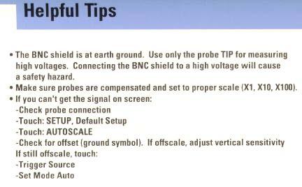
24 3. Digital 2 Channel 100 MHz Osciloscope-HP54600B QUICK START Turn ON the unit, after the self test, this unit will display Normal Screen. NOTE: Before any reading is made, press the SET-UP key, all the soft keys under the screen are displayed now. Press the default set-up key, then save the setting by pressing the save key from the soft key panel under the screen. Now you are ready to use this unit! When the unit is connected to any Source, (or your circuit) or from the OUTPUT of the Function Generator, it will display your signal at the scope. Pressing the auto range key, you will have a better look of the signal at the scope To measure the Amplitude of the signal: Press the Voltage key from the from panel of the scope; all the soft keys under the scope screen will change to: Source( 1 & 2), V p-p, V avg, V rms are now available. By pressing any of these keys, the unit will show them. Clear them (any measure you did) by pressing the Clear_Meas key; then the unit is ready for new set of measurements instructions. If any adjustment in the circuit is needed, turn off the power source, make the required change, restart the power supply, and press the auto-scale key for a new set of measurements. 24
25 To Measure Frequency: Press the Time Key, you are now in time domain mode, all the soft keys under the screen will change to Source (1 & 2), frequency, Period, Duty Cycle. All these measurements can be made by pressing the key for the desired task. If new measures are needed, adjust the circuit (if necessary), press auto scale key, and continue with your measurements. Note: Change the source for the proper reading of your input (Channel 1 or Channel 2). Other measurements possible with the scope are Voltage (eg, rms) or Time (T 1 and T 2 ) can be made by pressing the Cursor key and take the cursor to the desired type of measure (horizontal or vertical value). Accordingly with the Mode selected at the moment of this operation, you will be able to check (Voltage pp ) if in Voltage Mode by moving the cursor knob for up or down. If in Time Mode, T 1 and T 2 can be measured by moving the left or right knob for T 1 or T 2 values. Note: After using these units, be sure ALL of these units are turned OFF before you leave the lab. Before attempting to operate this unit as Spectrum Analyzer see your Lab Instructor for HELP! See below for more details. Features 100 MHz bandwidth 2 Channels Sweep speeds from 5 s/div to 2 ns/div Up to 1.5 Million points/sec screen update rate 25

26 Getting Familiar with the Scope Front Panel Controls 26

27 Display Features 27

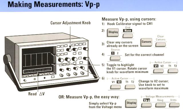
28 List of Procedures The procedures used in the processes of making measurements with the HP 54645A oscilloscope in the various labs are listed in this section for easy referencing. Adjusting the Oscilloscope Display Press OR Press followed by the Full softkey Press and press the leftmost softkey until On is highlighted Position the signal on the display using the position knob Adjust Time/Div until at least 2 periods are displayed Change the vertical sensitivity with the Volts/Div knob until the waveform fills the display without clipping Press and press the leftmost softkey until On is highlighted and repeat previous Steps Vp-p 1. Hook calibrator signal to CH1 2. Press key 3. Press Voltage Key 28
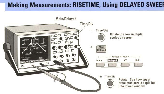
29 4. Press soft key Vp-p 5. Vp-p value will move toward to the bottom left on the screen. Vrms 1. Hook calibrator signal to CH1 2. Press key 3. Press Voltage Key 4. Press soft key Vrms 5. Vrms value will move toward to the bottom midle on the screen. Frequency 1. Press key 2. Press Time Key 3. Press Frequency soft key 4. Frequency value will move toward to the bottom left on the screen. Period 1. Press key 2. Press Time Key 3. Press Period soft key 4. Period value will move toward to the bottom on the screen. RiseTime 1. Press key 2. Press Key 3. Press soft key 29

30 4. Press soft key RiseTime 5. RiseTime value will move toward to the bottom on the screen. 6. If answer needs more resolution, rotate for best display: Offset 1. Press ± key 2. Press soft key Menu 3. Press Soft key Offset 4. Use the Cursor knob to adjust Selecting the Trigger Source 1. Press 2. Press the softkey corresponding to the desired source Setting the Trigger Mode 1. Press 2. Press the softkey corresponding to the desired mode Averaging To turn averaging on: 1. Press 2. Press the Average softkey 3. Press the # Average softkey until the desired number of averages is selected. To turn averaging off: 30
31 1. Press 2. Press the Normal softkey Measuring Signal Amplitudes 1. Press 2. Press the Clear Meas softkey to clear the last measurement 3. Press the Source softkey until channel 1 is selected 4. Press the Next Menu softkey until the VAMP softkey is displayed 5. Press the VAMP softkey to display the amplitude of the waveform 6. Repeat for channel 2 (Don t clear the last measurement) Measuring the Phase Shift between Channels 1. Press 2. Press the Next Menu softkey until the Define Thresholds softkey is displayed on the far left side of the screen 3. Press the Measure Phase softkey 31

32 Taking Measurements (Examples) 32

33 FFT 33

34 34
35 Specifications HP 54600B Performance Characteristics Form Factor Bandwidth Number of Channels Simultaneous Channels Simultaneous Maximum Sampling Rate/Ch One Ch. only max. sampling rate Max. Single Shot bandwidth Max. Record Length Min. Vertical Sensitivity Maximum Vertical Sensitivity Rise time Number of Bits Input Impedance Input Coupling Maximum Input Voltage Main time base - lowest Main time base - highest Bench top 100 MHz 2 ch 2 ch 20 MSa/s 20 MSa/s 2 MHz 4000 pt/sec 2 mv/div 5 V/div 3.5 ns 8 bits 1 MΩ AC,DC,GND 400 Vrms 2 ns/div 5 s/div Time base accuracy 0.01 % Trigger Source Trigger Modes Trigger Sensitivity Minimum Glitch Trigger Display Type Display Size External, Internal Auto, Single, Trigger 3.5 mv 1 ns CRT Monochrome cm 35

36 4. Function Generator/Arbitrary Wave Generator - HP33120A QUICK START Turn ON the unit, it will self test and Addr 10 will come on. 1 KHz at 100 mv pp sinusoidal is the Default for this unit. The shape of the signal can be changed by pressing the proper key from the front panel of the unit. To change the frequency: Press the frequency key, then, rotating the knob at the front panel will adjust the frequency from 0.1 Hz to 15 MHz. To change the magnitude of the signal: Press the Amplitude (Amp) key. Rotate the same knob used to adjust frequency, and select the desired unit (Hz, KHz, MHz), until you reach the desired frequency. For Signal Modulation Mode (AM, FM, FSK): Press the blue key (+ AM). From the scope, rotate the Time/Division knob until the signal appears at desired shape. You can stop the scope to have a better view of the modulated signal by pressing stop key from the front panel of the scope. After viewing the signal, press the Run key. To change the amount of modulation; while in modulation mode, press the (blue key + the Amp (level) key). By rotating the adjustment knob will change the % of modulation from 1 to 120 % of modulation. 36
37 Note: When connecting the generator to the scope, be sure that the correct measurement is read, adjust the Function Generator to High Impedance reading with these steps: 1. Press Blue Key then Enter 2. Press 3 times the key 3. Press 2 times key. 4. Press 1 time key. 5. Finally, press the Enter Key The unit is now in High Impedance and in Sync with the scope! Also, remember to press the Auto-Scale at the scope to reset the measurement. 37
38 Introduction A function generator allows you to create a wide variety of synthesized electrical signals and waveforms. Figure 1 shows the most common functions such as the sine, square, triangle and ramp functions. 38
=v A sin(2*pi*ft) + V OFF in which f is frequency, V A the amplitude, and V OFF if the offset voltage as shown in Figure 2.")

39 Figure 1: Waveforms generated by a function generator Each of the waveforms can be adjusted through the front panel controls or remotely for frequency, amplitude and DC offset voltage. For example, a sine function described by the following equation, v(t)=v A sin(2*pi*ft) + V OFF in which f is frequency, V A the amplitude, and V OFF if the offset voltage as shown in Figure 2. Instead of amplitude one often uses the RMS (Root Mean Square) value to express the signal voltage level. For a sine wave the RMS value is the amplitude divided by the square root of 2 or V RMS = V A /1.41. The RMS is the most useful way to specify AC signal amplitudes. Figure 2: Sine wave with amplitude V A, frequency f, and offset V OFF The generator can be remotely programmed and read by computer via a General Purpose Interface Board (GPIB). Basics of the Function Generator (HP33120A) The function generator in the ECE lab is based on digital signal processing (DSP) methods. The DSP is able to generate complex and arbitrary functions. A simplified block diagram is shown in Figure 3. 39
 and R T is the Thevenin resistance (= output resistance).")

40 Figure 3: Block diagram of the HP33120A waveform generator. Any circuit can be represented by the Thevenin's equivalent circuit. This is shown in Figure 4a. V gen represents the waveform (sine, pulse, etc.) and R T is the Thevenin resistance (= output resistance). Figure 4: (a) Thevenin's equivalent circuit; (b) voltage divider between the output and load resistors. Important is that this output resistance of the function generator is 50 Ohm. This implies that the actual output voltage one measures over the load will vary with the load resistance because of the voltage divider, as shown in Figure 4b. The output amplitude is calibrated for a 50 Ohm load resistance, which means that the voltage shown on the function generator's display panel corresponds to the actual voltage V LOAD over the load only when the resistance is equal to 50 Ohm. In other words, the value of V gen is double of the value displayed (or selected) by the function generator. If the function generator's output is measured with no load connected (=open circuit or infinite resistance), the output voltage will be twice the displayed amplitude. Thus, be careful when applying the output voltage of the function generator to a circuit which input resistance is different from 50 Ohm. To get accurate test result, you have to set function generator to high-impedance load (High-Z) mode. How to set function generator to high-impedance load (High-Z) mode, please refer II.2.a. 40


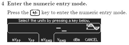
41 Functions and Use of HP 33120A The front panel of the HP 33120A is shown in Figure 5. There are two outputs on the right of front-panel. One is OUTPUT -- the regular output terminal at which the specified waveform appears. The other output SYNC is often used as a trigger signal. Both output terminals are of the "BNC" type, which can be connected to a coaxial cable (a shielded cable). Figure 5: Front panel of the HP 33120A function generator/waveform generator a. Front Panel Number Entry To set the amplitude, frequency and offset voltage of a waveform, just enter numbers. Numbers can be entered in three ways: 1. Use big knob. One of the digits will be blinking on the display. During you turning knob, the blinking number will increase or decrease. 2. Use the arrow keys <, >, ^, v. 3. Use the Enter Number mode. Press ENTER NUMBER key, followed by the number (see green number keys on the front panel) and the units, and then press ENTER key(see Figure 6). To cancel the number mode, press SHIFT and CANCEL keys. Figure 6: Entering numbers using the "Enter Number" mode. 41
42 At power-on the function generator will output a sine wave of 1 KHz and amplitude of 100mV peak-to-peak (for a 50 Ohm load resistance). You can select another function or change the frequency, amplitude and offset voltage by pressing MODIFY keys. b. Selection of a standard waveform 1. Press the key with the icon of the desired waveform (sine, pulse, triangle, or ramp) as shown in Figure 5. An annunciator will show the selected waveform 2. Arbitrary waveforms can be selected, see details on coming section. 3. Press Modify key to modify the amplitude, frequency (and duty cycle in case of a pulse). See details on coming section c. Frequency selection Procedure: 1. Press the FREQ key (Figures 5 and 7). 2. Enter frequency with number key, the frequency annunciator will display. 3. Press one of the arrow keys to set the units (MHz, KHz, HZ). Figure 7: Using the Modify Keys to select the frequency, amplitude, offset or duty cycle d. Amplitude selection Select the Amplitude Mode by: 1. Press the AMPL key (Figure 7). 2. Enter the number for the amplitude. 3. Press the arrow keys to select amplitude in (m) V peak-to-peak (VPP), in (m) V RMS or db. Notice: The function generator is calibrated for a 50 Ohm load which implies that the output voltage will be different from the one selected when the load resistance is different from 50 Ohm. The minimum amplitude is 50 mv PP and the maximum 10 V PP for a 50 Ohm load (and 100mV PP and 20 VPP, respectively, for an open circuit). 42

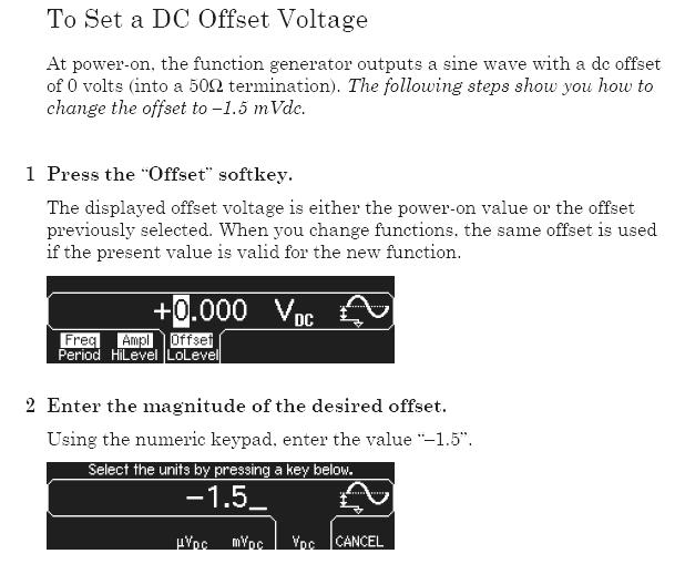
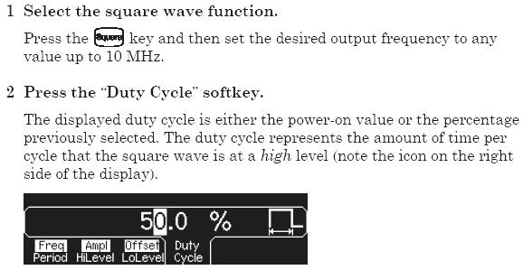
43 e. Offset Voltage selection The waveforms default offset voltage is 0V, which means that the waveform will vary between a positive and negative value. If you want to offset the waveform, you will need to add an offset voltage as defined in Figure 2. To set the offset voltage: 1. Select the Offset Modify Mode. 2. Enter the number for the offset voltage. 3. Press ENTER key. f. Duty Cycle selection This applies to square waves only, and default duty cycle is 50% and can be changed by: 1. Press the key with the square wave icon. 2. Press the SHIFT and %DUTY keys (see Figure 7). 3. Enter the number in %. 4. Press the ENTER key. g. Output of an arbitrary waveform There are five built-in arbitrary waveforms stored in memory. It includes sinc, exponential rise and fall, negative ramp and a cardiac function (which simulates the heart beat of human), refer Figure 8. In addition, one of five waveforms can be user-defined. Figure 8: The five built-in arbitrary functions 43
. 4. When the desired function is displayed press the ENTER key. 5.")
44 To see the list of arbitrary functions: 1. Press SHIFT key. 2. Press ARB LIST key. 3. The first choice displayed is SINC. The display will show SINC for about 10 seconds. Press the > keys or Round knob to change the functions (EXP-RISE, EXP-FALL, NEG-RAMP, and CARDIAC). 4. When the desired function is displayed press the ENTER key. 5. Now, the amplitude, frequency and offset voltage are able to be changed. 6. Once you have selected an arbitrary waveform, this function will be assigned to the ARB key. Every time you press ARB key, this waveform will be selected. 7. And then, the parameters of this function can be changed. Figure 9: Selecting the Arbitrary Functions by pressing the SHIFT and ARB LIST keys Front-panel Menu of the HP33120A Waveform Generator a. Selection of the output impedance (50 Ohm or High Z) To get accurate test result, you have to set function generator to high-impedance load (High-Z) mode. How to set function generator to high-impedance load (High-Z) mode: 1. Press Menu On (Shift-Enter). You can see A: MOD MENU on the display. 2. Press > key three times, you can see D: SYS MENU on the display. 3. Press v key once, you can see 1: OUT TERM on display. It means output termination Resistance of your load. 4. Press v again, you can see 50 OHM on the display. 5. Press > key, you can see HIGH Z on display. 6. Press Enter, the equipment is set as high impendence loads. To get High-Z, this procedure must go through by manually each time turn on the HP 33120A. 44

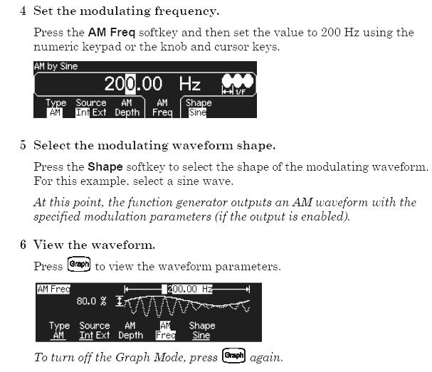
45 b. Advanced modification of a standard waveform Modulation waveform using amplitude or frequency (AM and FM), generate Frequency Shift Keying (FSK) signal, frequency sweep, or a burst waveform. The menu is organized in a top down tree structure as shown in Figure 10. You move down the menu tree using the ^ or v keys, and move within a level using the > and < keys. The top level lets you select the main functions, the 2nd level is the command level, and the 3rd level is the parameter level. Figure 10: Menu organization To turn the menu on press the SHIFT and MENU On/Off keys; Press the >, <, ^ and v keys to navigate the menu; To enter a command press the ENTER key; To recall the last menu command that was executed, press the SHIFT RECALL_MENU keys. Example: Advanced modification of standard waveforms The standard waveforms can be modified to create more complex ones which can be used in various applications. As an example, one can modulate the amplitude (AM) or frequency (FM) of the waveforms in Figure 11 for an AM modulated sinusoid. The carrier frequency amplitude is being modulated by the lower frequency - sinusoid, and is called modulating signal. The modulating signal could be any signal (For example: a speech signal or music, as the case for AM radio transmission). 45
. AM annunciator will be on. 4. Select the shape of the modulating waveform on Menu. 5. Press SHIFT and RECALL_MENU buttons, it will get in AM menu and displays AM SHAPE.")

46 Figure 11: AM modulated sinusoid To modulate a sinusoid: 1. Select the sine function by pressing the key with the sine icon. 2. Adjust the frequency and amplitude using the modify keys. 3. Select AM mode by pressing the SHIFT and AM keys (see Figures 5 and 12). AM annunciator will be on. 4. Select the shape of the modulating waveform on Menu. 5. Press SHIFT and RECALL_MENU buttons, it will get in AM menu and displays AM SHAPE. 6. Press v to select SINE waveform. 7. Press ENTER. 8. Set the modulating frequency by pressing SHIFT and FREQ key (Figure 12). AM annunciator will flash. 9. Set the frequency of the modulating signal by number keys. 10. Press SHIFT and LEVEL key to set the modulation depth. The modulation depth is between 0 and 120%. (Please see Figure 10 for the definition). Figure 12: Selecting the AM mode Storing arbitrary waveforms Once you have set up your arbitrary waveform such as the AM modulated waveform, you can store them for later use and recall it any time. You can store them up to 4 waveforms. To store a waveform: 46
47 1. Press the SHIFT key. 2. Press STORE key. 3. Press the number (from 1 to 4) of the register where you want to store the function. To recall the waveform: 1. Press RECALL key. 2. Press number of the register. Specifications: o Frequency characteristics: Sine and square: 100µHz - 15 MHz Triangle and Ramp: 100µHz-100KHz o Arbitrary waveform: Length: 8 to 16,000 points Resolution: 12 bits Sample rate: 40 MSa/sec Non-volatile memory (arbitrary waveforms): four 16k o Output: (into 50 Ohm): Amplitude: 50mVpp - 10 Vpp. Offset: +/- 5Vpk ac+dc Output impedance: 50 Ohm 47

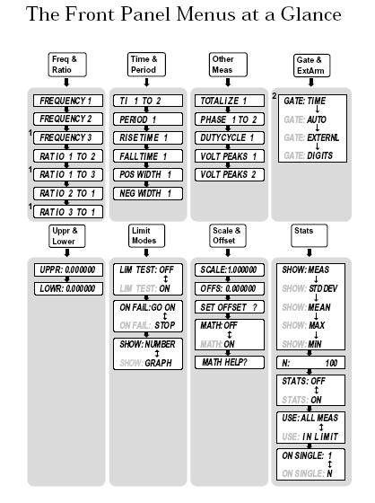
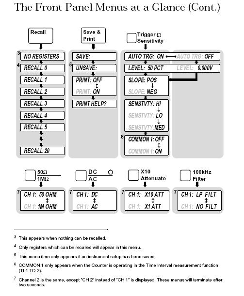
48 5. HP 53131A DC-225MHZ 10 Digit Universal Counter QUICK START Turn the unit ON; the unit will self test, given Address 03 and will set to Channel 1 (Default). Connect your leads cables from channel 1 to the circuit under test. See the counter manual for how to measure frequencies below 100 Hz. The unit will show the exact frequency. To select another channel, press Frequency button until Freq 2 appears. Connect the circuit under test to channel 2 and read the measurements from the display of the unit. New frequency checked will be held for convenience reading when needed. Also, ratios from freq 1 to 2 or freq 3 can be obtained by pressing frequency button until the desired ratio appears. Note: Both channels under test Must be connected during ratio reading. Other readings can be made, such as: The period T 1 to T 2, Rise time 1, Falltime 1, (Positive Width 1, and Negative Width 1), obtained by pressing the Time and Period button on the front panel until the desired measurement is found. Other measurements are possible, such as: Phase of signal 1 to signal 2 (phase difference between both signals). Duty cycle: defined as the positive pulse width divided by the period. Also, Volts Peak: Voltage 1 and Voltage 2 for both signal strength. See more details below. 48
49 Key Features 225 MHz Basic Bandwidth on both channels Basic Universal Counter with Time Interval Capability 500 pixels single shot Time Interval resolution GP-IB and RS232 Fast Continuous-Count measurement technique Intuilink Software included 49
50 50
51 51
52 52
53 53
54 54
55 Making Measurements This quick manual is designed to give you hands-on experience in using the 53131A counter. Universal Counter can make various measurements. Required Equipments A Universal Counter 2. Signal Source ( Example: 33220A Function/Arbitrary Waveform Generator) 3. 1 BNC cable Measuring Common Signals That s easy. 1. counter displays the measured frequency around 1 KHz. The frequency is not exactly 1 KHz, it is due to the calibration of both the counter and the function generator. Notice that a few of the digits shown on the counter are changing. 2. Change the function generator output to a square wave by pressing the [Square] button. Observe that the counter's digits are changing less than before. This demonstrates the general fact that counter works better with fast edge signals (square wave) rather than slow edge signals (sine wave). This is due to trigger errors that are greater with the slower edge signals. Low Frequency Measurements A little less automatic. Let s see what happens if we try to measure a low frequency. Turn the power off on both the function generator and the counter. Function Generator Set-up 1. Power the Function Generator on. The default frequency of 1 KHz appears. 2. Change the frequency to 2 Hz. First pressing < and > locate the digit you want to change on the generator s front panel. Second press V and Λ to change the value to be 2 Hz. 3. Connect the 33220A Output BNC to the 53131A CHANNEL 1 input BNC. 4. Power on the counter. It passes self-test, and displays This is a problem sign which is typically caused by either no frequency signal or an incorrect frequency signal that is not stable. You set a stable 2Hz frequency on the function generator so What could be wrong? 55
56 Counter Set-up Notice the 5 buttons associated with Ch 1 on the Counter. 5. Press the [Trigger Sensitivity] button. The display shows Auto Trg On. The ON is flashing. Whenever a portion of the display is flashing, that means that there are choices for the flashing element. This element can be changed by pressing one of the arrow buttons just to the right of the display. 6. Set AUTO TRG: OFF. Auto trigger does not work at frequencies below 100 Hz. The counter may be set at the wrong trigger voltage. 7. Press [Trigger Sensitivity] again. You can manually set the trigger level. The generator is outputting a 2 Hz signal symmetric about 0 V (no offset) so an appropriate trigger level is 0 V. 8. Use the arrow buttons to set the trigger level to 0V. Use the horizontal arrows to select the digit. When the correct digit is flashing, use the vertical arrows to increment/decrement the digit s value. 9. Press the [Enter] button next to the arrows. 10. Press [Run] on the main keyboard panel. You will now get a reading around 2 Hz. For low frequencies you should also use DC coupling. Here is how: 11. Set DC coupling for Ch 1 (press the [DC/AC] button near Ch 1). You should see a good solid measure of the 2Hz frequency. Time Interval Measurements The counter can do time interval measurements between a signal edge on Ch 1 (start edge) and an edge of a different signal on Ch 2 (stop edge). The counter can also make time interval measurements on one signal. The start edge and stop edge are both on one signal. To do this, the counter is set to put a single signal on both channels at the same time by selecting common signal routing as explained below. Cycle the power for both the counter and the generator to make sure you are starting at a known state Function Generator Set-up Do not connect the BNC to counter, yet. Soft keys are buttons just below the display. Their function / labels change depending on where you are at within the configuration menu. When instructed to press a soft key, look for the label in the display and press the corresponding button. 1. Turn the functions generator on 56
57 2. Select pulse by press pulse button. 3. Set frequency to 2 KHz. 4. Set amplitude to 1 Vpp. (Press Ampl key, press < and > move flash digit and set value by pressing V and Λ ) 5. Set offset to 0V. (Press Offset key, change the value to be 0 ). 6. Set pulse frequency to be 2KHz. ( Press Freq key, set value to be 2KHz) 7. Connect BNC to counter Ch1. Counter Set-up 8. Turn the counter on and wait for it to complete the start-up sequence. 9. Press the [Time and Period] button. T1 to 2 is displayed. 10. Press the Ch 1 [Trigger Sensitivity] button. AUTO TRG: ON is displayed. 11. Pressing the [Trigger Sensitivity] button again, it shows LEVEL: 50 PCT Make sure to set 50 by pressing [Enter] before continuing. 12. Press [Trigger Sensitivity] again, SLOPE: POS. 13. Press again, SENSTVTY: HI 14. Press again to see COMMON 1: OFF. This means Ch 1 is not connected to Ch 2 internally inside the counter. Note that the OFF portion of the displayed message is flashing. That means it can be changed by pressing one of the arrow buttons to the right of the display. 15. Set COMMON 1: ON Now Ch 1 is connected internally to Ch 2 and they see the same signal. 16. Press the same buttons (steps 10 through 15) for Ch 2 that you did for Ch 1 to ensure that the settings are the same for both Channels. 17. Press the [Run] button. The display shows the time interval measurement between the rising edges of two adjacent pulses in the signal. For a 2 KHz signal this should be 1/2000 = 500 u sec. You are most likely seeing a time interval considerably smaller than 500usec. 18. Press the [Gate and Ext Arm] button until it displays DELAY: NONE Note that the None portion of the display is flashing. 19. Press an arrow button (to the right of the display) to display DELAY: TIME. 20. Press the [Gate & Ext Arm] button to display TIME: s. 21. Set the time to 100 usec using the arrow buttons. (set.00010s by using the horizontal arrows to move digits, use the vertical arrows to increment/decrement numbers) 22. Press [Enter] located by the arrow buttons. 57
58 Note: You must press [Enter], otherwise, your setting will be lost. 23. Press [Run]. You should see a display of 500 usec. Slowing Down the Display by Using Stats Counter Set-up 1. Press the [State] button. 2. Set SHOW MEAS to display SHOW MEAN by pressing the arrow key. 3. Press [Stats] again and set N to Press [Enter] 5. Press [Run] Notice that the display has slowed down and is easier to read. Totalize Measurements The counter s totalize feature simply means counting triggered edges. For instance, we now have a signal from the 33220A that is a pulse occurring at a 2 khz rate. So, if we were to totalize this signal for 1 second, the total shown should be 2000 ±1 count. Counter Set-up 1. Press the [Other Meas] button once to display TOTALIZE 1. If you wait a moment, you will see the display show 200. Now press the [Gate & ExtArm] button and see GATE: TIME. Notice that TIME is flashing. Check the available choices with the arrow buttons. The choices are TIME, AUTO, and EXTERNAL. 2. Set the flashing field to TIME. 3. Press the [Gate & ExtArm] button again to display.100 seconds. 4. Use the arrow buttons to set the gate time to 1 second. 5. Press [Enter]. 6. Press [Run]. The display now shows That is, the counter is counting 2000 pulses in 1 second on channel 1. CAUTION here. The 1-second gate that you set is not very accurate. Instead of deriving the 1-second gate from the precision clock time base, it is derived from the u-processor clock. Why the count that they expected is not being displayed? The reason is, most likely because of an error in the time gate, not the count mechanism itself. To make really accurate time gated TOTALIZE measurements you must supply a precision time length pulse to the 58
59 external gate. 7. Press [Gate & ExtArm] twice to display GATE: TIME (with time flashing). 8. Set GATE: AUTO using the arrow buttons. 9. Press [Run]. The counter counts and counts in a continuous mode until you Press the [Stop/Single] button. Pressing [Run] again resets the totalizer back to zero. There is no way to just pause the Totalize function; you must stop it and that automatically resets it. The last choice, External, allows you to set a positive or negative going edge as the start for TOTALIZE. It also allows you to set a positive or negative going edge as the stop for TOTALIZE. Limit Testing It is possible to do limit testing with the 53131A counters. For example, you may want to know whenever a measured frequency goes outside a predefined upper limit or lower limit. Cycle the power on the counter and the function generator to ensure a known starting point. Function Generator Set-up Turn the function generator on. It will be set to a default 1 KHz sine wave with an amplitude of 100 mvpp. Counter Set-up 1. Turn the counter on. After the start up sequence, the counter will read approximately 1 KHz. 2. Press the [Limit Modes] button. Note that the LIM TEST: OFF is displayed. 3. Press an arrow button to turn LIM TEST: ON. 4. Press the [Limit Modes] button twice to display SHOW: NUMBER. 5. Press the [Uppr & Lower] button and set the upper limit of 1010 Hz using the arrow buttons. 6. Press [Enter]. 7. Press the [Uppr & Lower] button again and set the lower limit to 990 Hz. 8. Press [Enter]. 9. Press [Run]. The counter should be displaying a measurement of about 1 khz. 10. Change the frequency of the function generator to frequencies above and below the limits. (Use the horizontal arrow to move digits, turn the knob to Increment / decrement frequency). 59
60 Note: The Limit light comes on on the counter display when the frequency is above or below the limit. Limit test graphic mode There is a convenient and unique way to display in and out of limit conditions using these counters. 1. Press the [Limit Modes] button until SHOW: NUMBER is displayed. 2. Press the arrow buttons to display SHOW: GRAPH. 3. Press [Run]. Notice that an asterisk and two colons are shown in the counter s display. 4. Change the generator s frequency slowly so that it exceeds both the lower and upper frequency limits. The asterisk represents the current frequency with respect to the limits (two colons). 60
61 61
62 62
63 63
64 64
65 65
66 66
67 67
68 68
69 69
70 70
71 71

72 6. Function/Arbitrary Waveform Generator HP33220A 20 MHz Specification HP 33220A function/arbitrary waveform generator uses direct digital synthesis (DDS) techniques to create stable, low-distortion output signals and provides easy access to standard sine, square, ramp, triangle, pulse waveforms, and also, you can create custom waveforms using the 50 MSa/s, 14 bit, 64 K-point arbitrary waveform function. It supports variable-edge pulse function and create PWM. The 33220A includes USB, LAN and GPIB interfaces. 20 MHz sine and square waveforms Ramp, triangle, pulse, noise, and DC waveforms 14-bit, 50 MSa/s, 64 K-point arbitrary waveforms AM, FM, PM, FSK, and PWM modulation types Linear & logarithmic sweeps and burst operation modes Graph mode for visual verification of signal settings USB, GPIB and LAN interfaces included 72

73 73


74 The Front Panel Display at a Glance 74

75 Front-Panel Number Entry To Set the Output Frequency 75


76 To Set Output Amplitude 76

77 77


78 78


79 79


80 80

81 81

82 82

83 83


84 84

85 85

86 86
87 87

88 88
89 89
90 90
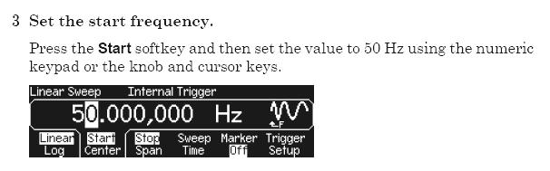
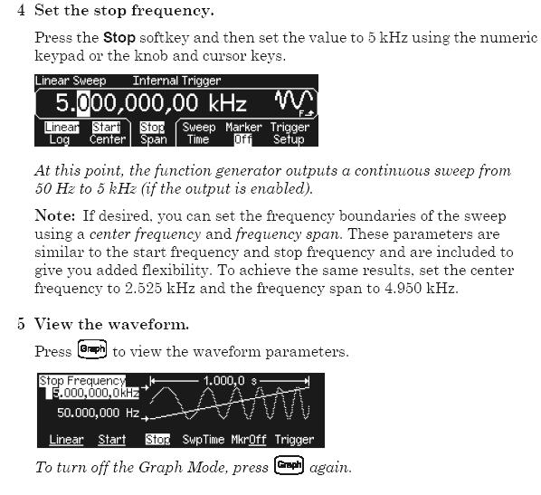
HP 33120A Function Generator / Arbitrary Waveform Generator
 Note: Unless otherwise indicated, this manual applies to all Serial Numbers. The HP 33120A is a high-performance 15 MHz synthesized function generator with built-in arbitrary waveform capability. Its combination
ME 365 EXPERIMENT 1 FAMILIARIZATION WITH COMMONLY USED INSTRUMENTATION
 Objectives: ME 365 EXPERIMENT 1 FAMILIARIZATION WITH COMMONLY USED INSTRUMENTATION The primary goal of this laboratory is to study the operation and limitations of several commonly used pieces of instrumentation:
Introduction to basic laboratory instruments
 Introduction to basic laboratory instruments 1. OBJECTIVES... 2 2. LABORATORY SAFETY... 2 3. BASIC LABORATORY INSTRUMENTS... 2 4. USING A DC POWER SUPPLY... 2 5. USING A FUNCTION GENERATOR... 3 5.1 TURN
L107 Lab. LAB basic HW Tools. Manual PS E3630A. E9340A LogicWave PC Logic Analyzer
 LAB basic HW Tools L107 Lab Toolbar add-ins for Word, Excel (Scope, DMM, [PS]) Waveform Editor (ARB gen) Data Capture (Scope) Data Capture Toolbars (Word, Excel) Waveform Editor /D Manual PS E3630A DUT
The University of Jordan Mechatronics Engineering Department Electronics Lab.( ) Experiment 1: Lab Equipment Familiarization
 Experiment 1: Lab Equipment Familiarization") The University of Jordan Mechatronics Engineering Department Electronics Lab.(0908322) Experiment 1: Lab Equipment Familiarization Objectives To be familiar with the main blocks of the oscilloscope and
The University of Jordan Mechatronics Engineering Department Electronics Lab.(0908322) Experiment 1: Lab Equipment Familiarization Objectives To be familiar with the main blocks of the oscilloscope and
MULT SWP X1K K VERN START FREQ DURATION AMPLITUDE 0 TTL OUT RAMP
 Signal Generators This document is a quick reference guide to the operation of the signal generators available in the laboratories. Major functions will be covered, but some features such as their sweep
Introduction to Basic Laboratory Instruments
 Introduction to Contents: 1. Objectives... 2 2. Laboratory Safety... 2 3.... 2 4. Using a DC Power Supply... 2 5. Using a Function Generator... 3 5.1 Turn on the Instrument... 3 5.2 Setting Signal Type...
Agilent 33250A 80 MHz Function / Arbitrary Waveform Generator. User s Guide
 User s Guide Publication Number 33250-90002 (order as 33250-90100 manual set) Edition 2, March 2003 Copyright Agilent Technologies, Inc. 2000, 2003 For Safety information, Warranties, and Regulatory information,
Combinational logic: Breadboard adders
 ! ENEE 245: Digital Circuits & Systems Lab Lab 1 Combinational logic: Breadboard adders ENEE 245: Digital Circuits and Systems Laboratory Lab 1 Objectives The objectives of this laboratory are the following:
Lab #1 Lab Introduction
 Cir cuit s 212 Lab Lab #1 Lab Introduction Special Information for this Lab s Report Because this is a one-week lab, please hand in your lab report for this lab at the beginning of next week s lab. The
ECE 480: SENIOR DESIGN LABORATORY
 ECE 480: SENIOR DESIGN LABORATORY DEPARTMENT OF ELECTRICAL AND COMPUTER ENGINEERING MICHIGAN STATE UNIVERSITY I. TITLE: Lab I - Introduction to the Oscilloscope, Function Generator, Digital Multimeter
ECE 53A: Fundamentals of Electrical Engineering I
 ECE 53A: Fundamentals of Electrical Engineering I Laboratory Assignment #1: Instrument Operation, Basic Resistor Measurements and Kirchhoff s Laws Fall 2007 General Guidelines: - Record data and observations
332:223 Principles of Electrical Engineering I Laboratory Experiment #2 Title: Function Generators and Oscilloscopes Suggested Equipment:
 RUTGERS UNIVERSITY The State University of New Jersey School of Engineering Department Of Electrical and Computer Engineering 332:223 Principles of Electrical Engineering I Laboratory Experiment #2 Title:
Notes on Experiment #1
 Notes on Experiment #1 Bring graph paper (cm cm is best) From this week on, be sure to print a copy of each experiment and bring it with you to lab. There will not be any experiment copies available in
LAB I. INTRODUCTION TO LAB EQUIPMENT
 1. OBJECTIVE LAB I. INTRODUCTION TO LAB EQUIPMENT In this lab you will learn how to properly operate the oscilloscope Agilent MSO6032A, the Keithley Source Measure Unit (SMU) 2430, the function generator
Introduction to basic laboratory instruments
 BEE 233 Laboratory-1 Introduction to basic laboratory instruments 1. Objectives To learn safety procedures in the laboratory. To learn how to use basic laboratory instruments: power supply, function generator,
Dual Channel Function/Arbitrary Waveform Generators 4050 Series
 Data Sheet Dual Channel Function/Arbitrary Waveform Generators The Dual Channel Function/Arbitrary Waveform Generators are capable of generating stable and precise sine, square, triangle, pulse, and arbitrary
EXPERIMENT NUMBER 2 BASIC OSCILLOSCOPE OPERATIONS
 1 EXPERIMENT NUMBER 2 BASIC OSCILLOSCOPE OPERATIONS The oscilloscope is the most versatile and most important tool in this lab and is probably the best tool an electrical engineer uses. This outline guides
Digital Storage Oscilloscopes Models 2540B, 2542B, 2540B-GEN, 2542B-GEN
 Data Sheet Digital Storage Oscilloscopes Models 2540B, 2542B, 2540B-GEN, 2542B-GEN The 2540B, 2542B, 2540B-GEN, and 2542B-GEN dual channel 60 MHz and 100 MHz digital storage oscilloscopes deliver performance
Lab 0: Introduction to basic laboratory instruments. Revised by Dan Hoang & Tai-Chang Chen 03/30/2009
 Lab 0: Introduction to basic laboratory instruments Revised by Dan Hoang & Tai-Chang Chen 03/30/2009 1. Objectives 1. To learn safety procedures in the laboratory. 2. To learn how to use basic laboratory
UNIVERSITY OF CALIFORNIA, BERKELEY. EE40: Introduction to Microelectronic Circuits Lab 1. Introduction to Circuits and Instruments Guide
 UNERSTY OF CALFORNA, BERKELEY EE40: ntroduction to Microelectronic Circuits Lab 1 ntroduction to Circuits and nstruments Guide 1. Objectives The electronic circuit is the basis for all branches of electrical
Dual Channel Function/Arbitrary Waveform Generators 4050B Series
 Data Sheet Dual Channel Function/Arbitrary Waveform Generators The Dual Channel Function/ Arbitrary Waveform Generators are capable of generating stable and precise sine, square, triangle, pulse, and arbitrary
Introduction to Lab Instruments
 ECE316, Experiment 00, 2017 Communications Lab, University of Toronto Introduction to Lab Instruments Bruno Korst - bkf@comm.utoronto.ca Abstract This experiment will review the use of three lab instruments
Model MHz Arbitrary Waveform Generator Specifications
 50MHz Arbitrary Waveform Generator s DISPLAY: Graph mode for visual verification of signal settings. CAPABILITY: Standard waveforms: Sine, Square, Ramp, Triangle, Pulse, Noise, DC Built-in arbitrary waveforms:
Dual Channel Function/Arbitrary Waveform Generators 4050 Series
 Data Sheet Dual Channel Function/Arbitrary Waveform Generators The Dual Channel Function/Arbitrary Waveform Generators are capable of generating stable and precise sine, square, triangle, pulse, and arbitrary
Experiment 1: Instrument Familiarization (8/28/06)
") Electrical Measurement Issues Experiment 1: Instrument Familiarization (8/28/06) Electrical measurements are only as meaningful as the quality of the measurement techniques and the instrumentation applied
Electrical Measurement Issues Experiment 1: Instrument Familiarization (8/28/06) Electrical measurements are only as meaningful as the quality of the measurement techniques and the instrumentation applied
Equipment: You will use the bench power supply, function generator and oscilloscope.
 EE203 Lab #0 Laboratory Equipment and Measurement Techniques Purpose Your objective in this lab is to gain familiarity with the properties and effective use of the lab power supply, function generator
LAB I. INTRODUCTION TO LAB EQUIPMENT
 LAB I. INTRODUCTION TO LAB EQUIPMENT 1. OBJECTIVE In this lab you will learn how to properly operate the basic bench equipment used for characterizing active devices: 1. Oscilloscope (Keysight DSOX 1102A),
Publication Number ATFxxB Series DDS FUNCTION WAVEFORM GENERATOR. User s Guide
 Publication Number 101201 ATFxxB Series DDS FUNCTION WAVEFORM GENERATOR User s Guide Introduction This user's guide is used for all models of ATFxxB series of DDS function generator. xx in the model number
Experiment #2: Introduction to Lab Equipment: Function Generator, Oscilloscope, and Multisim
 SCHOOL OF ENGINEERING AND APPLIED SCIENCE DEPARTMENT OF ELECTRICAL AND COMPUTER ENGINEERING ECE 2110: CIRCUIT THEORY LABORATORY Experiment #2: Introduction to Lab Equipment: Function Generator, Oscilloscope,
CIRCUIT-TEST ELECTRONICS
 USER'S MANUAL Sweep Function Generator with Counter SWF-8030 CIRCUIT-TEST ELECTRONICS www.circuittest.com TABLE OF CONTENTS SAFETY INFORMATION...page 3 INTRODUCTION... 4 SPECIFICATIONS... 5 FRONT PANEL
EE 201 Function / Arbitrary Waveform Generator and Oscilloscope Tutorial
 EE 201 Function / Arbitrary Waveform Generator and Oscilloscope Tutorial 1 This is a programmed learning instruction manual. It is written for the Agilent DSO3202A Digital Storage Oscilloscope. The prerequisite
Laboratory 3 (drawn from lab text by Alciatore)
") Laboratory 3 (drawn from lab text by Alciatore) The Oscilloscope Required Components: 1 10 resistor 2 100 resistors 2 lk resistors 1 2k resistor 2 4.7M resistors 1 0.F capacitor 1 0.1 F capacitor 1 1.0uF
Laboratory 3 (drawn from lab text by Alciatore) The Oscilloscope Required Components: 1 10 resistor 2 100 resistors 2 lk resistors 1 2k resistor 2 4.7M resistors 1 0.F capacitor 1 0.1 F capacitor 1 1.0uF
ENGR 210 Lab 6 Use of the Function Generator & Oscilloscope
 ENGR 210 Lab 6 Use of the Function Generator & Oscilloscope In this laboratory you will learn to use two additional instruments in the laboratory, namely the function/arbitrary waveform generator, which
Agilent 33210A 10 MHz Function / Arbitrary Waveform Generator. User s Guide
 User s Guide Publication Number 33210-90001 (order as 33210-90000 manual set) Edition 1, August 2008 Copyright 2008 Agilent Technologies, Inc. Agilent 33210A 10 MHz Function / Arbitrary Waveform Generator
University of Jordan School of Engineering Electrical Engineering Department. EE 204 Electrical Engineering Lab
 University of Jordan School of Engineering Electrical Engineering Department EE 204 Electrical Engineering Lab EXPERIMENT 1 MEASUREMENT DEVICES Prepared by: Prof. Mohammed Hawa EXPERIMENT 1 MEASUREMENT
Arbitrary/Function Waveform Generators 4075B Series
 Data Sheet Arbitrary/Function Waveform Generators Point-by-Point Signal Integrity The Arbitrary/Function Waveform Generators are versatile high-performance single- and dual-channel arbitrary waveform generators
Analog Arts SG985 SG884 SG834 SG814 Product Specifications [1]
![Analog Arts SG985 SG884 SG834 SG814 Product Specifications [1]](/thumbs/94/122371203.jpg "Analog Arts SG985 SG884 SG834 SG814 Product Specifications [1]") www.analogarts.com Analog Arts SG985 SG884 SG834 SG814 Product Specifications [1] 1. These models include: an oscilloscope, a spectrum analyzer, a data recorder, a frequency & phase meter, and an arbitrary
www.analogarts.com Analog Arts SG985 SG884 SG834 SG814 Product Specifications [1] 1. These models include: an oscilloscope, a spectrum analyzer, a data recorder, a frequency & phase meter, and an arbitrary
Laboratory Equipment Instruction Manual 2011
 University of Toronto Department of Electrical and Computer Engineering Instrumentation Laboratory GB341 Laboratory Equipment Instruction Manual 2011 Page 1. Wires and Cables A-2 2. Protoboard A-3 3. DC
Agilent 33220A. 20 MHz Waveform Generator. User's Guide. Agilent Technologies
 Agilent 33220A 20 MHz Waveform Generator User's Guide Agilent Technologies User s Guide Publication Number 33220-90002 (order as 33220-90100 manual set) Edition 4, May 2007 Copyright 2003, 2005, 2007 Agilent
Sirindhorn International Institute of Technology Thammasat University at Rangsit
 Sirindhorn International Institute of Technology Thammasat University at Rangsit School of Information, Computer and Communication Technology COURSE : ECS 210 Basic Electrical Engineering Lab INSTRUCTOR
UNIVERSITY OF CALIFORNIA, SANTA BARBARA Department of Electrical and Computer Engineering. ECE 2A & 2B Laboratory Equipment Information
 UNIVERSITY OF CALIFORNIA, SANTA BARBARA Department of Electrical and Computer Engineering ECE 2A & 2B Laboratory Equipment Information Table of Contents Digital Multi-Meter (DMM)... 1 Features... 1 Using
Analog Arts SL987 SL957 SL937 SL917 Product Specifications [1]
![Analog Arts SL987 SL957 SL937 SL917 Product Specifications [1]](/thumbs/95/126095980.jpg "Analog Arts SL987 SL957 SL937 SL917 Product Specifications [1]") www.analogarts.com Analog Arts SL987 SL957 SL937 SL917 Product Specifications [1] 1. These models include: an oscilloscope, a spectrum analyzer, a data recorder, a frequency & phase meter, an arbitrary
www.analogarts.com Analog Arts SL987 SL957 SL937 SL917 Product Specifications [1] 1. These models include: an oscilloscope, a spectrum analyzer, a data recorder, a frequency & phase meter, an arbitrary
Experiment 1: Instrument Familiarization
 Electrical Measurement Issues Experiment 1: Instrument Familiarization Electrical measurements are only as meaningful as the quality of the measurement techniques and the instrumentation applied to the
Rigol DG1022A Function / Arbitrary Waveform Generator
 Rigol DG1022A Function / Arbitrary Waveform Generator The Rigol DG1000 series Dual-Channel Function/Arbitrary Waveform Generator adopts DDS (Direct Digital Synthesis) technology to provide stable, high-precision,
EENG-201 Experiment # 4: Function Generator, Oscilloscope
 EENG-201 Experiment # 4: Function Generator, Oscilloscope I. Objectives Upon completion of this experiment, the student should be able to 1. To become familiar with the use of a function generator. 2.
Virtual Lab 1: Introduction to Instrumentation
 Virtual Lab 1: Introduction to Instrumentation By: Steve Badelt and Daniel D. Stancil Department of Electrical and Computer Engineering Carnegie Mellon University Pittsburgh, PA Purpose: Measurements and
Agilent 33220A Function Generator Tutorial
 Contents UNIVERSITY OF CALIFORNIA AT BERKELEY College of Engineering Department of Electrical Engineering and Computer Sciences EE105 Lab Experiments Agilent 33220A Function Generator Tutorial 1 Introduction
Analog Arts SF990 SF880 SF830 Product Specifications
 1 www.analogarts.com Analog Arts SF990 SF880 SF830 Product Specifications Analog Arts reserves the right to change, modify, add or delete portions of any one of its specifications at any time, without
Analog Arts SF900 SF650 SF610 Product Specifications
 www.analogarts.com Analog Arts SF900 SF650 SF610 Product Specifications Analog Arts reserves the right to change, modify, add or delete portions of any one of its specifications at any time, without prior
EE EXPERIMENT 1 (2 DAYS) BASIC OSCILLOSCOPE OPERATIONS INTRODUCTION DAY 1
 BASIC OSCILLOSCOPE OPERATIONS INTRODUCTION DAY 1") EE 2101 - EXPERIMENT 1 (2 DAYS) BASIC OSCILLOSCOPE OPERATIONS INTRODUCTION The oscilloscope is the most versatile and most important tool in this lab and is probably the best tool an electrical engineer
EE 2101 - EXPERIMENT 1 (2 DAYS) BASIC OSCILLOSCOPE OPERATIONS INTRODUCTION The oscilloscope is the most versatile and most important tool in this lab and is probably the best tool an electrical engineer
2 Oscilloscope Familiarization
 Lab 2 Oscilloscope Familiarization What You Need To Know: Voltages and currents in an electronic circuit as in a CD player, mobile phone or TV set vary in time. Throughout the course you will investigate
EE-4022 Experiment 2 Amplitude Modulation (AM)
") EE-4022 MILWAUKEE SCHOOL OF ENGINEERING 2015 Page 2-1 Student objectives: EE-4022 Experiment 2 Amplitude Modulation (AM) In this experiment the student will use laboratory modules to implement operations
EE-4022 MILWAUKEE SCHOOL OF ENGINEERING 2015 Page 2-1 Student objectives: EE-4022 Experiment 2 Amplitude Modulation (AM) In this experiment the student will use laboratory modules to implement operations
electrical noise and interference, environmental changes, instrument resolution, or uncertainties in the measurement process itself.
 MUST 382 / EELE 491 Spring 2014 Basic Lab Equipment and Measurements Electrical laboratory work depends upon various devices to supply power to a circuit, to generate controlled input signals, and for
RIGOL Data Sheet. DS1000E, DS1000D Series Digital Oscilloscopes DS1102E, DS1052E, DS1102D, DS1052D. Product Overview. Easy to Use Design.
 RIGOL Data Sheet DS1000E, DS1000D Series Digital Oscilloscopes DS1102E, DS1052E, DS1102D, DS1052D Product Overview The DS1000E, DS1000D series instruments are economical, high-performance digital oscilloscopes.
ECE 2274 Lab 1 (Intro)
") ECE 2274 Lab 1 (Intro) Richard Dumene: Spring 2018 Revised: Richard Cooper: Spring 2018 Forward (DO NOT TURN IN) The purpose of this lab course is to familiarize you with high-end lab equipment, and train
ECE 2274 Lab 1 (Intro) Richard Dumene: Spring 2018 Revised: Richard Cooper: Spring 2018 Forward (DO NOT TURN IN) The purpose of this lab course is to familiarize you with high-end lab equipment, and train
A semester of Experiments for ECE 225
 A semester of Experiments for ECE 225 Contents General Lab Instructions... 3 Notes on Experiment #1... 4 ECE 225 Experiment #1 Introduction to the function generator and the oscilloscope... 5 Notes on
A semester of Experiments for ECE 225
 A semester of Experiments for ECE 225 Contents General Lab Instructions... 3 Notes on Experiment #1... 4 ECE 225 Experiment #1 Introduction to the function generator and the oscilloscope... 5 Notes on
Group: Names: Resistor Band Colors Measured Value ( ) R 1 : 1k R 2 : 1k R 3 : 2k R 4 : 1M R 5 : 1M
 R 1 : 1k R 2 : 1k R 3 : 2k R 4 : 1M R 5 : 1M") 2.4 Laboratory Procedure / Summary Sheet Group: Names: (1) Select five separate resistors whose nominal values are listed below. Record the band colors for each resistor in the table below. Then connect
2.4 Laboratory Procedure / Summary Sheet Group: Names: (1) Select five separate resistors whose nominal values are listed below. Record the band colors for each resistor in the table below. Then connect
Appendix A: Laboratory Equipment Manual
 Appendix A: Laboratory Equipment Manual 1. Introduction: This appendix is a manual for equipment used in experiments 1-8. As a part of this series of laboratory exercises, students must acquire a minimum
RIGOL Data Sheet. DG1000 Series Dual-Channel Function/Arbitrary Waveform Generator. Product Overview. Main Features. Applications. Easy to Use Design
 RIGOL Data Sheet DG1000 Series Dual-Channel Function/Arbitrary Waveform Generator Product Overview DG1000 series Dual-Channel Function/Arbitrary Waveform Generators adopt DDS technology, which enables
INTRODUCTION TO ENGINEERING AND LABORATORY EXPERIENCE Spring, 2015
 INTRODUCTION TO ENGINEERING AND LABORATORY EXPERIENCE Spring, 2015 Saeid Rahimi, Ph.D. Jack Ou, Ph.D. Engineering Science Sonoma State University A SONOMA STATE UNIVERSITY PUBLICATION CONTENTS 1 Electronic
RIGOL Data Sheet. DG3000 Series Function/Arbitrary Waveform Generator DG3121A, DG3101A, DG3061A. Product Overview. Easy to Use Design.
 RIGOL Data Sheet DG3000 Series Function/Arbitrary Waveform Generator DG3121A, DG3101A, DG3061A Product Overview DG3000 Series Function/Arbitrary Waveform Generators adopt DDS technology, which enables
Sept 13 Pre-lab due Sept 12; Lab memo due Sept 19 at the START of lab time, 1:10pm
 Sept 13 Pre-lab due Sept 12; Lab memo due Sept 19 at the START of lab time, 1:10pm EGR 220: Engineering Circuit Theory Lab 1: Introduction to Laboratory Equipment Pre-lab Read through the entire lab handout
LAB II. INTRODUCTION TO LAB EQUIPMENT
 1. OBJECTIVE LAB II. INTRODUCTION TO LAB EQUIPMENT In this lab you will learn how to properly operate the oscilloscope Keysight DSOX1102A, the Keithley Source Measure Unit (SMU) 2430, the function generator
P a g e 1 ST985. TDR Cable Analyzer Instruction Manual. Analog Arts Inc.
 P a g e 1 ST985 TDR Cable Analyzer Instruction Manual Analog Arts Inc. www.analogarts.com P a g e 2 Contents Software Installation... 4 Specifications... 4 Handling Precautions... 4 Operation Instruction...
EECS 318 Electronics Lab Laboratory #2 Electronic Test Equipment
 EECS 318 Electronics Lab Laboratory #2 Electronic Test Equipment Objectives: The purpose of this laboratory is to acquaint you with the electronic sources and measuring equipment you will be using throughout
University of Utah Electrical & Computer Engineering Department ECE 2210/2200 Lab 4 Oscilloscope
 University of Utah Electrical & Computer Engineering Department ECE 2210/2200 Lab 4 Oscilloscope Objectives 1 Introduce the Oscilloscope and learn some uses. 2 Observe Audio signals. 3 Introduce the Signal
54645D. Mixed Signal Oscilloscope
 54645D Mixed Signal Oscilloscope Page 1 of 42 Instructions for the use of the 54645D Mixed Signal Oscilloscope This pamphlet is intended to give you (the student) an overview on the use of the 54645D Mixed
Laboratory 2 (drawn from lab text by Alciatore)
") Laboratory 2 (drawn from lab text by Alciatore) Instrument Familiarization and Basic Electrical Relations Required Components: 2 1k resistors 2 1M resistors 1 2k resistor Objectives This exercise is designed
Laboratory 2 (drawn from lab text by Alciatore) Instrument Familiarization and Basic Electrical Relations Required Components: 2 1k resistors 2 1M resistors 1 2k resistor Objectives This exercise is designed
DS1102E, DS1052E, DS1102D, DS1052D
 RIGOL Data Sheet DS1000E, DS1000D Series Digital Oscilloscopes DS1102E, DS1052E, DS1102D, DS1052D Product Overview DS1000E, DS1000D series are kinds of economical digital oscilloscope with high-performance.
Function Generator Guide Tektronix AFG3102
 Tektronix AFG3102 ersion 2008-Jan-1 Dept. of Electrical & Computer Engineering Portland State University Copyright 2008 Portland State University 1 Basic Information This guide provides basic instructions
Lab #5 Steady State Power Analysis
 Lab #5 Steady State Power Analysis Steady state power analysis refers to the power analysis of circuits that have one or more sinusoid stimuli. This lab covers the concepts of RMS voltage, maximum power
Notes on Experiment #3
 Notes on Experiment #3 This week you learn to measure voltage, current, and resistance with the digital multimeter (DMM) You must practice measuring each of these quantities (especially current) as much
University of Saskatchewan Electrical Engineering Laboratory Equipment Manual. Analog Meters
 Analog Meters There are a wide variety of analog meters available in the labs. There are ac & dc voltmeters, ac & dc ammeters, ac & dc wattmeters, and several true rms voltmeters. They are all designed
Specifications for DS1000CA Series
 Revised December, 2009 RIGOL Specifications for DS1000CA Series All specifications apply to the DS1000CA Series Oscilloscopes unless noted otherwise. To meet these specifications, two conditions must first
80MHz/50MHz Arbitrary Function Generator
 80MHz/50MHz Arbitrary Function Generator AFG-3000 Series NEW The AFG-3000 Series is an Arbitrary Waveform and Digital-Synthesized Function Generator designed for industrial, scientific research and educational
RIGOL Data Sheet. DG2000 Series Function/Arbitrary Waveform Generator DG2041A, DG2021A. Product Overview. Main Features.
 RIGOL Data Sheet DG2000 Series Function/Arbitrary Waveform Generator DG2041A, DG2021A Product Overview DG2000 Series Function/Arbitrary Waveform Generators adopt DDS technology, which enables to generate
Laboratory 2. Lab 2. Instrument Familiarization and Basic Electrical Relations. Required Components: 2 1k resistors 2 1M resistors 1 2k resistor
 Laboratory 2 nstrument Familiarization and Basic Electrical Relations Required Components: 2 1k resistors 2 1M resistors 1 2k resistor 2.1 Objectives This exercise is designed to acquaint you with the
Agilent E3631A Triple Output DC Power Supply
 Service Guide 3DUW1XPEHU( $SULO )RU:DUUDQW\LQIRUPDWLRQUHIHUWRWKHEDFNRIWKHPDQXDO &RS\ULJKW$JLOHQW7HFKQRORJLHV,QF $OO5LJKWV5HVHUYHG $JLOHQW($ '&3RZHU6XSSO\ The Agilent Technologies E3631A is a high performance
Frequency and Time Domain Representation of Sinusoidal Signals
 Frequency and Time Domain Representation of Sinusoidal Signals By: Larry Dunleavy Wireless and Microwave Instruments University of South Florida Objectives 1. To review representations of sinusoidal signals
APPENDIX D DISCUSSION OF ELECTRONIC INSTRUMENTS
 APPENDIX D DISCUSSION OF ELECTRONIC INSTRUMENTS DC POWER SUPPLIES We will discuss these instruments one at a time, starting with the DC power supply. The simplest DC power supplies are batteries which
MODEL 9050 EXTENDED SPECIFICATIONS. 50ppm TRANSPORTABLE CALIBRATOR
 MODEL 9050 EXTENDED SPECIFICATIONS Ü 50ppm TRANSPORTABLE CALIBRATOR 9050A EXTENDED SPECIFICATIONS General Specifications TRANSMILLE LTD Warm Up Time Double the time since last used up to 20 minutes maximum
LLS - Introduction to Equipment
 Published on Advanced Lab (http://experimentationlab.berkeley.edu) Home > LLS - Introduction to Equipment LLS - Introduction to Equipment All pages in this lab 1. Low Light Signal Measurements [1] 2. Introduction
Lab 1: Basic Lab Equipment and Measurements
 Abstract: Lab 1: Basic Lab Equipment and Measurements This lab exercise introduces the basic measurement instruments that will be used throughout the course. These instruments include multimeters, oscilloscopes,
5MHz FUNCTION GENERATOR
 5MHz FUNCTION GENERATOR MODEL GF-8056 User s Manual Elenco TM Electronics, Inc. Copyright 2004 by Elenco TM Electronics, Inc. All rights reserved. 753117 No part of this book shall be reproduced by any
PHYSICS 171 UNIVERSITY PHYSICS LAB II. Experiment 4. Alternating Current Measurement
 PHYSICS 171 UNIVERSITY PHYSICS LAB II Experiment 4 Alternating Current Measurement Equipment: Supplies: Oscilloscope, Function Generator. Filament Transformer. A sine wave A.C. signal has three basic properties:
DG5000 series Waveform Generators
 DG5000 series Waveform Generators DG5000 is a multifunctional generator that combines many functions in one, including Function Generator, Arbitrary Waveform Generator, IQ Baseband /IQ IF, Frequency Hopping
CPE 310L EMBEDDED SYSTEM DESIGN LABORATORY
 CPE 310L EMBEDDED SYSTEM DESIGN LABORATORY LABORATORY 1 LAB SAFETY & LAB EQUIPMENT USE TUTORIAL DEPARTMENT OF ELECTRICAL AND COMPUTER ENGINEERING UNIVERSITY OF NEVADA, LAS VEGAS GOALS: Introduce laboratory
Using Circuits, Signals and Instruments
 Using Circuits, Signals and Instruments To be ignorant of one s ignorance is the malady of the ignorant. A. B. Alcott (1799-1888) Some knowledge of electrical and electronic technology is essential for
AME140 Lab #2 INTRODUCTION TO ELECTRONIC TEST EQUIPMENT AND BASIC ELECTRONICS MEASUREMENTS
 INTRODUCTION TO ELECTRONIC TEST EQUIPMENT AND BASIC ELECTRONICS MEASUREMENTS The purpose of this document is to guide students through a few simple activities to increase familiarity with basic electronics
WaveStation Function/Arbitrary Waveform Generators
 WaveStation Function/Arbitrary Waveform Generators Key Features High performance with 14-bit, 125 MS/s and 16 kpts 2 channels on all models Large 3.5 color display for easy waveform preview Over 40 built-in
RIGOL Data Sheet. DS1000E, DS1000D Series Digital Oscilloscopes DS1102E, DS1052E, DS1102D, DS1052D. Product Overview. Applications. Easy to Use Design
 RIGOL Data Sheet DS1000E, DS1000D Series Digital Oscilloscopes DS1102E, DS1052E, DS1102D, DS1052D Product Overview DS1000E, DS1000D series are kinds of economical digital oscilloscope with high-performance.
Sonoma State University Department of Engineering Science Spring 2017
 EE 110 Introduction to Engineering & Laboratory Experience Saeid Rahimi, Ph.D. Lab 4 Introduction to AC Measurements (I) AC signals, Function Generators and Oscilloscopes Function Generator (AC) Battery
WaveStation Function/Arbitrary Waveform Generators
 WaveStation Function/Arbitrary Waveform Generators Key Features High performance with 14-bit, 125 MS/s and 16 kpts 2 channels on all models Large 3.5 color display for easy waveform preview Over 40 built-in
DG5000 Series Specifications
 DG5000 Series Specifications All the specifications can be guaranteed if the following two conditions are met unless where noted. The generator is within the calibration period and has performed self-calibration.
WaveStation Function/Arbitrary Waveform Generators
 Function/Arbitrary Waveform Generators Key Features High performance with 14-bit waveform generation, up to 500 MS/s sample rate and up to 512 kpts memory 2 channels on all models Large color display for
RIGOL. Quick Guide. DG2000 Series Function/Arbitrary Waveform Generator. Sept RIGOL Technologies, Inc.
 Quick Guide DG2000 Series Function/Arbitrary Waveform Generator Sept. 2010 RIGOL Technologies, Inc. Guaranty and Declaration Copyright 2010 RIGOL Technologies, Inc. All Rights Reserved. Trademark Information
Press Cursors and use the appropriate X and Y functions to measure period and peak-peak voltage of the square wave.
 Equipment Review To assure that everyone is up to speed for the hurdles ahead, the first lab of the semester is traditionally an easy review of electrical laboratory fundamentals. There will, however,
G5100A: 50 MHz Arbitrary Function Generator
 G5100A: 50 MHz Arbitrary Function Generator Key Features 50 MHz Sine Wave 25 MHz Square Wave Pulse, Ramp, Triangle, Noise, and DC waveforms AM, FM, PM, FSK, and PWM modulation types Linear & logarithmic