ADAM-4022T Serial Base Dual Loops PID Controller User s Manual
|
|
|
- Clement Dalton
- 5 years ago
- Views:
Transcription
1 ADAM-422T Serial Base Dual Loops PID Controller User s Manual
2 Warning Message : The ADAM-422T is recommended to be used in general purposed air conditioning application. When using this product in applications that required particular safety or when using this product in important facility, pay attention to the safety of the overall system and equipment. For example, install fail-safe mechanism, carry out redundancy checks and periodic inspections, and adopt other appropriate safety measures as required.
3 ADAM-422T dual loop PID Controller Introduction Function The ADAM-422T dual loop PID controller is a Serial-based controller. It was designed as the product of Advantech s ADAM-4 series with Serial based PID controller With an excellent accuracy ±.15%, the ADAM-422T is an ideal controller for temperature and other process variable in heating and cooling application, test and environmental work. Easy to operate ADAM-422T utility software can help you to select input and range configuration, set the operating parameter (SP, Sv, Pv.. etc) for your process control needed. ADAM-422T utility software also integrates the trend chart to help you to monitor and debug your control setting. Industrial Design ADAM-422T was designed to use in industrial environment. It can be installed in standard DIN rail inside the cabinet. And it can be powered by unregulated 1~Vdc to meet the various power supplied source in field. It also withstands ambient temperature up to 6 o C and resists the effects of vibration and mechanical shock.

4 Wiring & Installation The ADAM-422T is a Dual loop PID controller. There are three analog input, one analog output, one digital input and one digital out put for each loop usage. The analog input channels is 16-bit, universal signal accepted design. It provides programmable input ranges on all channels. It accepts various analog inputs +/-1V, ~2mA and 4~2mA. The analog output channel is 12 bit with ~1V, ~2mA and 4~2mA acceptable input type. Each analog channel is allowed to configure an individual range for several applications. The digital input can be configured as the emergency shutdown trigger input and the digital output is designed as the common alarm output. The PID loop function can be disabled by ADAM-422T utility software tool, that is, ADAM-422T can be a pure universal I/O module after disabling the PID loop function. ADAM-422T Fig. 7-1 ADAM-422T Drawing
5 Application Wiring Fig. 7-2 Analog Input/Output Wiring Diagram Fig. 7- Digital Input/Output Wiring Diagram

6 Jumper Setting P AI P1 AI P AI1 P1 AI1 P AO P1 AO Initial Switch JP1 Loop 1 AI Channel JP2 Loop 1 AI Channel 1 JP Loop AI Channel JP4 Loop AI Channel 1 JP5,JP6 Loop AO Channel JP7,JP8 Loop 1 AO Channel I: Current Signal V: Voltage Signal Input Default: V Output default: I Note: When using RTD or Thermistor, please set the jumper to voltage signal setting. Initial Switch Setting You can set the initial mode by switching the switch to INIT, after setting your ADAM-422T, you can switch to NORMAL mode.

7 Operation Interface Open the ADAM 4 Utility Software, the software tool will auto-scan the ADAM 4 module through the network. Clicking the 422T in the system tree of left dialog block, User can select Modbus or BACnet as supported Protocol Clicking the 422T in the system tree of left dialog block to go to ADAM-422T configuration page. In this page, user can configure the input channel, output channel and PID loop function. And ADAM-422T support two communication protocol Modbus/RTU and BACnet MS/TP. User can select the supported protocol in this page.


8 Input Channel Configuration Page : In ADAM-422T input channel configuration page, user can enable the input channel, select the input signal type and select the DI status. Channel, 1 is the analog input as the control parameter for PID loop and channel 2, is for PID loop 1 when the PID loop function is enabled. ADAM-422T also support MODBUS/RTU protocol, user can see the detail MODBUS address register number for each channel in this page. It can be a very important reference for communication work. Input Channel Config. Page Input Signal Type Select MODBUS Register Address

9 Calibration ADAM-422T input channel configuration also support Zero and Span calibration function. Clicking the Zero Calib and Span Calib bottom to go to the calibration dialog block, user can set the initial zero value and span range then click the Execute bottom to proceed the channel calibration work. Please refer the following pictures for operation guideline.

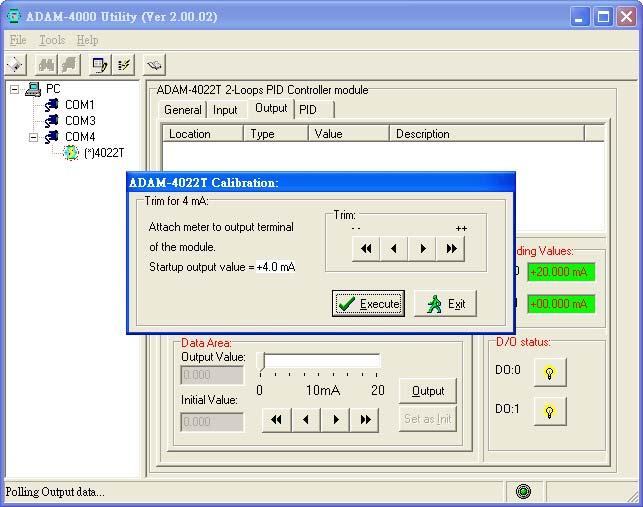
10 Output Channel Configuration Page : For output channel configuration, there are two analog output channel in ADAM-422T. The output channel is used as the control output for PID loop and channel 1 is for PID loop 1 when PID loop function is enabled. The configuration for output channel is quite similar as input configuration. User can easily to finish the configuration with the friendly operating interface of ADAM-422T utility software. Channel Calibration Output Signal Type Select Analog Manual Output Setting ADAM-422T can be a pure universal I/O module when PID being set in Free mode. User can use Data Area to setup the analog output to send a specific value for such kind application. This function can also be controlled with MODBUS/TCP protocol through Ethernet network for HMI/SCADA application. For calibrating the analog output channel, user can use external certificated signal measured device as calibrator then use the Trim for 4mA and Trim for 2mA calibrating function to fine tuning the channel output signal for calibration requirement.
11

12 PID Loop Configuration ADAM-422T is designed as a stand alone PID controller. We offer a very convenient software tool for user to configure the PID controlled parameter. In this configuration page, there is a real time trend chart to show the values changing of SV, PV and MV. It is very helpful for user to monitor and diagnose the PID control situation. For the functionality of the bottom in PID configuration page, please refer the explanation of the following table. Bottom Function PID loop number Control Mode Selection : Free : Stop PID Control Auto : PID Loop Automatically Manual : Manual Control


13 Parameter Setting and Monitoring SV : Setpoint Value PV : Process Value MV : Controlled Output Value PV, MV Alarm Status PID Setting Button (go to PID setting page) PID Tuning Button (go to PID tuning page) After finishing the setup work in configuration page, please click the setting bottom to go to the detail parameter setting screen.

14 PV/SV Setting : Button SV Range High SV Range Low PV Range High PV Range Low Low Pass Filter Interval (msec) Alarm H-High Alarm High Alarm Low Alarm L-Low Function PID Algorithm: Standard: Standard PID calculation. DIFF First: Differentiation as first priority. SV high limit value SV low limit value PV high limit value PV low limit value Low Pass Filter set value Low Pass Filter Calculation : MV Feedback = ing MV x Filter Value + Previous MV x (1- Filter Value) PID loop sensing time interval SV & PV High High alarm setpoint SV & PV High alarm setpoint SV & PV Low Low alarm setpoint SV & PV Low alarm setpoint
 Action, The \"MV\" decreases when the \"PV\" increases.")
15 MV Setting Button Range High Range Low Filter (.~1.) MV Init. Value MV Output High MV Output Low MV E-Stop Value Function PID Action: Control Action Mode Setting Direct: Direct (Heating) Action, The "MV" decreases when the "PV" increases. Reverse: Reverse (Cooling) Action, The "MV" increases when the "PV" increases. MV/FB high limit value MV/FB low limit value Filter set value Setting MV initial value MV output high limit MV output low limit Setting MV frozen value while PID being emerged shutdown

16 For PID parameter tuning, please refer the PID tuning page. In this page, the P, I, D parameters can be adjusted to achieve the optimal control result. The real time trend chart provides a powerful tool for user to supervise the parameters adjustment result.
17 Appendix A ASC II Command Set Command Description Remarks % AANNTTCCFF Sets the address, input mode, baud rate, checksum status (NN: new address TT: always CC: baudrate FF: bit6=1 checksum enable bit6=1 checksum disable)!nn: OK $AAB channel diagnostic!aammmm: OK (m: normal 1 over highest value 2 over lowest value invalid calibration) $AAF $AAM $AA $AA1 $AA2 $AA2Ci $AA2Cihhh $AACi Return the firmware version code from the specified module.!aaav.vv: OK Return the module name from the!aa422t: OK specified module Calibrate the analog input module to!aa: OK correct the gain error Calibrate the analog input module to!aa: OK correct the offset error Returns the configuration!aaccff: OK parameters. the MAX calibration value for!aacihhh: OK analog output (i: channel ~1) Calibrate the analog output to correct the MAX value (i: channel ~1 hhh: 12bits raw data) the MIN calibration value for analog output (i: channel ~1) $ AACihhh Calibrate the analog output to correct the MIN value (i: channel ~1 hhh: 12bits raw data) $AA5vv $AA6 $AA7 Enable/Disable multiplexing (vv: ~F) Asks a specified input module to return the status of all AI channels Asks a specified module to return the status of all DI/DO channels!aa: OK!AACihhh: OK!AA: OK!Aa: OK?Aa: error!aavv: OK!AAooii: OK
18 Command Description Remarks $AA7CiRrr Set the channel input range code (i: channel ~!AA: OK rr: range code) $AA8Ci the channel input range code (i: channel ~)!AACiRrr: OK $AA9Ci the channel output range code!aacirrr: OK $AA9CiRrr #AA #AAi #AAccdd #AACidd.ddd (i: channel ~1) Set the channel output range code. After setting, the output will be set to minimum value. (i: channel ~1 rr: range code) Return the input values from all channels of the specified analog input module Return the input value from the specified channel in the analog input module (i: channel ~) Set a single or all digital output channels. (cc: all channel, dd: ~ 1 channel, dd:~1 11 channel 1, dd:~1) Analog output to the specified channel (i: channel ~1 dd.ddd: engineering units)!aa: OK >+xx.xxx+xx.xxx+xx.xxx+xx.x xx: OK (format: V, ma is xx.xxx; RTD, Thermistor is xxx.xx) >+xx.xxx: OK >: OK >: OK #AAO all AO channel value >+xx.xxx+xx.xxx: OK #AAOi AO value from an output channel (i: channel ~1) >: OK #AAPRsscc PID value (ss: starting index, h~ffh cc: total tot read, MAX is 4h) #AAPWssvvvvvvvv Set PID value (ss: index, h~ffh vvvvvvvv: the long value) >aaaaaaaabbbbbbbb : OK each value use 8 HEX to indicate a long value >: OK
19 Appendix B Channel Specification Analog input channel Channel index in command Channel index in hardware LOOP Ain 1 LOOP Ain1 2 LOOP1 Ain LOOP1 Ain1 Input range code mapping and input calibration value Range code Range value Span calibration Zero calibration x7 4~2 ma 2. ma. ma x8 ~1 V 1 V V xd ~2 ma 2. ma. ma x2 PT-1 (-1~1 o C) 14 ohms 6 ohms a=.85 x21 PT-1 (~1 o C) 14 ohms 6 ohms a=.85 x22 PT-1 (~2 o C) 18 ohms 6 ohms a=.85 x2 PT-1 (~6 o C) 4 ohms 6 ohms a=.85 x24 PT-1 (-1~1 o C) 14 ohms 6 ohms a=.92 x25 PT-1 (~1 o C) 14 ohms 6 ohms a=.92 x26 PT-1 (~2 o C) 18 ohms 6 ohms a=.92 x27 PT-1 (~6 o C) 4 ohms 6 ohms a=.92 x2a PT-1 (-4~16 o C) 16 ohms 85 ohms x Thermistor K (~1 o C) 1 K ohms 2 ohms x1 Thermistor 1K (~1 o C) K ohms 8 ohms Output range code mapping Range code x x1 x2 Range value ~ 2 ma 4 ~ 2 ma ~ 1 V
20 Default setting Convert rate: 6 Hz Range code: x8 (1 V) Automatic ADC convert: false Channel mask: xf Auxiliary ADC: temperature sensor
21 Appendix C PID Parameters Table Modbus Register Loop Modbus Register Loop Code Open/Close Mode PID Mode Process value bare data Manipulator value bare data DI On/Off DO On/Off Set point Value PV RH (Range high) PV RL (Range low) MV RH (Range high) MV & FB RH (Range low) PV engineering data MV engineering data / Decimal Place Descriptions Enable/Disable PID loop function :Open mode -- no PID control, ADAM-422T will be a pure I/O module 1:Close mode enable PID loop function 2:Manual mode manual control analog output PID Mode Selection :Standard PID Calculation Mode 1:Differential First Mode PV value MV value DI for Emergency Shutdown Alarm DO On SV (Set point Value) PV Source Engineering Value Range high (PV RH must > PV RL) PV Source Engineering Value Range low (PV RL must < PV RH) MV Engineering Value Range high MV RH must > MV RL MV Engineering Value Range high MV RL must < MV RL PV Source engineering data MV engineering data MV engineering data can not only be automatically created by PID loop, but it also can be manual setup when PID loop set in manual mode. It will be translated as MV bare data AO output MV RL<MV engineering data<mv RH
22 Modbus Register Loop Modbus Register Loop 1 Code PID PV value PID SV value PV Filter value PV Range / Decimal Descriptions Place PID PV value PID SV value 1st order filter value for PV source <(PV Filter value/1)<1. : ~ 1V 1: - 2mA 2: 4-2mA : PT-1 (85) 1~1 C 4: PT-1 (85) ~1 C 5: PT-1 (85) ~2 C 6: PT-1 (85) ~6 C 7: PT-1 (92) 1~1 C 8: PT-1 (92) ~1 C 9: PT-1 (92) ~2 C 1: PT-1 (92) ~6 C 11: PT-1 4~16 C 12: Thermistor K ~1 C 1: Thermistor 1K ~1 C MV Range : ~ 1V 1: - 2mA 2: 4-2mA PID KP PID KI PID KD PID KP (PID) PID KI (PID) PID KD (PID) PID Proportional factor for PV Source PID KP=(Input value/1) PID Integrated factor for PV Source PID KI=(Input value/1) PID Differential factor for PV Source PID KD=(Input value/1) PID Proportional factor for PID calculation PID Integrated factor for PID calculation PID Differential factor for PID calculation
23 Modbus Register Loop Modbus Register Loop 1 Code / Decimal Place Descriptions Control loop period setting (msec) for PV <= : Loop empty > : Loop controlling Control loop period setting (msec)for PID <= : Loop empty > : Loop controlling Count down value of control loop period counting value<= then calculating PID loop Previous Loop Open/Close status Record the previous Loop Open or Close mode for Loop Initial set NSEC OLD NSEC Power recovery action setting MV Initial Value Last DI State Last DO State PV Alarm HH limit PV Alarm H limit PV Alarm LL limit Calculating the newest Loop interval as nsec Calculating the previous Loop interval as old nsec : maintaining the previous MV output keep PID open 1: setting the previous MV output as initial value and keeping PID Close 2: PID open, using MV initial value as MV output MV initial value for power recovery action Previous Scan DI State (reference for control program) Previous Scan DO State (reference for control program) PV Alarm High High Limit Value (<PV RH) PV Alarm High Limit Value (<PV RH & PV Alarm HH) PV Alarm Low Low Limit Value (>PV RL)
24 Modbus Register Loop Modbus Register Loop 1 Code / PV Alarm L limit PV Alarm Dead Band % PV Alarm Status Decimal Place Descriptions PV Alarm Low Limit Value (>PV RL & PV Alarm LL) PV Dead band % <(Input Value/1)%<1 % PV Alarm Status Normal 1:HH 2 H :L 4:LL MV Output High Limit MV Output High Limit (<MV RH) MV Output Low Limit MV Output Low Limit (>MV RL) MV Output Alarm Status MV Output Alarm Status Normal 1:H 2 L MV Emergency Value MV output value while emergency shutdown DI being active PV open wire flag Normal 1 Open wire PID Direct/Reverse Direct Mode 1 Reverse Mode SV High Limit SV Low Limit / SV High Limit value SV Low Limit value
25 MODBUS functions address mapping (1) Coils Address Mapping Table Index(Address) Remarks 1() DI status 2(1) DI 1 status ~16(2)~(15) Reserved (for those reserved area, there will be no effect if you set it) 17(16) DO status 18(17) DO 1 status 19~128(18)~(127) Reserved
26 (2) Registers Address Mapping Table Index(Address) Remarks 1() PAin value 2(1) PAin1 value (2) P1Ain value 4() P1Ain1 value 5~1(4)~(9) Reserved 11(1) AO value 12(11) AO 1 value 1~2(12)~(19) Reserved 21(2) PAin status (: normal; 1: over high; 2: over low; : invalid calibration) 22(21) PAin1 status 2(22) P1Ain status 24(2) P1Ain1 status 25~2(24)~(199) Reserved 21(2) PAin range code 22(21) PAin1 range code 2(22) P1Ain range code 24(2) P1Ain1 range code 25(24) AO range code 26(25) AO 1 range code 27~21(26)~(29) Reserved 211~212(21)~(211) Module name 21~214(212)~(21) Version 221(22) AI channel enable 1~1511 (999)~(151) PID data area (total 512 registers) Each PID data formed by two registers, for example: PID data[] = reg[1]*6555+reg[11] PID loop- occupies from PID data[] to PID [127]. PID loop-1 occupies from PID data[128] to PID [255]. For function x, x4, you can read 1 registers at most one time For function x1, you must set even number of registers at a time. The starting address must be an even number as well. You can only set at most 1 registers at a time. --- Not support
27 Appendix D BACnet objects supported Object type Instance Remarks Analog Input Refer to the PAin 1 Refer to the PAin1 2 Refer to the P1Ain Refer to the P1Ain1 Analog Output Refer to the AO 1 Refer to the AO1 Analog Value Refer to the PID SV of Loop 1 Refer to the PID MV of Loop 2 Refer to the PID SV of Loop Refer to the PID MV of Loop 1 Binary Input Refer to the DI 1 Refer to the DI 1 Binary Output Refer to the DO 1 Refer to the DO 1 Device is the default object instance Loop PID loop 1 PID loop 1 Multi-state Input Refer to the PV alarm in PID loop 1 Refer to the MV alarm in PID loop 2 Refer to the PV alarm in PID loop 1 Refer to the MV alarm in PID loop 1 Multi-state Output Refer to the Control Mode in PID loop 1 Refer to the Control Mode in PID loop 1
ADAM-4022T Serial Base Dual Loops PID Controller User s Manual
 ADAM-4022T Serial Base Dual Loops PID Controller User s Manual Warning Message : The ADAM-4022T is recommended to be used in general purposed air conditioning application. When using this product in applications
User s Manual. Model US1000 Digital Indicating Controller Functions. IM 5D1A01-02E 2nd Edition IM 5D1A01-02E
 User s Manual Model US1000 Digital Indicating Controller Functions 2nd Edition Introduction This instruction manual describes the functions of the US1000 Digital Indicating Controller in detail. Read
Universal Controller
 Universal Controller Overview and Configuration Manual Overview... 1 About this Manual... 1 Introduction... 5 Hardware Overview... 5 Software Overview... 7 Interpreting Flow Diagrams... 8 Foreign Language
DC1010/DC1020/DC1030/DC1040
 05/0 0-10-10-0-EN Page 1 of DC1010/DC1020/DC100/DC1040 DIGITAL CONTROLLERS Specification Overview The DC1000 Series are microprocessorbased controllers designed with a high degree of functionality and
APPENDIX APPENDIX A 1
 A 1 SPECIFICATIONS Ratings Supply voltage 100 to 240 VAC, 50/60 Hz 24 VAC, 50/60 Hz/24 VDC Operating voltage range 85 to 110% of rated supply voltage Power consumption 7VA 4VA/2.5W Sensor input Thermocouple
Series Temperature Controller Instruction Sheet
 2015/4/8 Series Temperature Controller Instruction Sheet Precaution DANGER! Caution! Electric Shock! Do not touch the AC terminals while the power is supplied to the controller to prevent electric shock.
Series Valve Temperature Controller. Instruction Sheet
 2013/10/03 Series Valve Temperature Controller Instruction Sheet Thank you very much for choosing Delta DTV series valve temperature controller. Please read this instruction sheet before using your DTV
PROCESS & TEMPERATURE CONTROLLERS
 PROCESS & TEMPERATURE CONTROLLERS NOVA PD54 Series Thermocouple, RTD, & Process Inputs High Accuracy Auto-Tuning PID Heating & Cooling Models Universal Power Supply 1-24 VAC Up to 3 Relays & 2 Analog Outputs
Series F4P Communications Guide
 Series F4P Communications Guide 1/4 DIN Temperature/Process Controller with Guided Setup 98 Registered Company Winona, Minnesota USA Watlow Controls 1241 Bundy Blvd., P.O. Box 5580, Winona, Minnesota USA
DC1010/DC1020/DC1030/DC1040/Compact type DIGITAL CONTROLLERS Specification
 01 May 20 30-10-10--EN Page 1 of DC1010/DC1020/DC1030/DC1040/Compact type DIGITAL CONTROLLERS Specification Overview The DC1000 Series are microprocessorbased controllers designed with a high degree of
- SMART TUNE- PID CONTROL - UNIVERSAL, 3 WIRE- TC, RTD AND LINEAR INPUT - AUX- REMOTE SET POINT/ TRIM INPUT - 2x ISOLATED CONTROL AND RETRANSMISSION
 ADVANCED - CONTROLLERS - SMART TUNE- PID CONTROL - UNIVERSAL, 3 WIRE- TC, RTD AND INPUT - AUX- REMOTE SET POINT/ TRIM INPUT - 2x ISOLATED CONTROL AND RETRANSMISSION (ma) OUTPUTS - 4x EVENT OR ALARM OUTPUTS
XC series PLC expansion module User Manual
 XC series PLC expansion module User Manual WUXI XINJE ELECTRIC CO., LTD. This manual includes some basic precautions which you should follow to keep you safe and protect the products. These precautions
Shenzhen ATC Technology CO.,LTD ATC. A-1 Serial Remote I/O Module. User Manual. V1.13 Edit:2018/01/
 ATC A-1 Serial Remote I/O Module User Manual V1.13 Edit:2018/01/30-1 - Catalogue 1.The introduction of Modbus protocol...- 3-1.1 Modbus protocol master-slave response process... - 3-1.2 Modbus register
CT435. PC Board Mount Temperature Controller
 CT435 PC Board Mount Temperature Controller Features Two RTD temperature sensor inputs: Pt100 or Pt1000. Wide temperature sensing range: -70 C to 650 C. All controller features are configurable through
OVEN INDUSTRIES, INC. Model 5C7-362
 OVEN INDUSTRIES, INC. OPERATING MANUAL Model 5C7-362 THERMOELECTRIC MODULE TEMPERATURE CONTROLLER TABLE OF CONTENTS Features... 1 Description... 2 Block Diagram... 3 RS232 Communications Connections...
Modbus Integration Integration for Modbus Functionality for VT8300 Series
 Modbus Integration Integration for Modbus Functionality for VT8300 Series Building Management System *For data visualization and analysis Modbus Controller VT8000 Series room controllers 2 TABLE OF CONTENTS
BusWorks 900EN Series Modbus TCP/IP 10/100M Industrial Ethernet I/O Modules
 BusWorks 900EN Series Modbus TCP/IP 10/100M Industrial Ethernet I/O Modules Six Differential Current Inputs Six Differential Voltage Inputs USER S MANUAL ACROMAG INCORPORATED Tel: (248) 295-0880 30765
ADAM 4000/4100 Series
 ADAM 4000/4100 Series Common Dimensions Communication RS-485 (2-wire) to host Speeds: 1200, 2400, 4800, 9600, 19200, 38400, 57600, 115200 bps (ADAM-4080, ADAM-4080D only support up to 38400 bps) Max. communication
INDEX. i 1. B Braking Resistor Dimensions: A 24 Braking Resistors: A 20 Braking Units: A 20. DURAPULSE AC Drive User Manual
 INDEX A AC Drive Cover: 1 6 Dimensions: 2 4 External Parts and Labels: 1 6 Heat Sink Fins: 1 6 Input Mode Switch (Sink/Source): 1 6 Introduction to DuraPulse GS3 AC drive: 1 3 Keypad: 1 6 Model Number
PROGRAMMABLE CONTROLLER
 Shimaden, Temperature and Humidity Control Specialists C %RH Series FP2 PROGRAMMABLE CONTROLLER approved UL applied BASIC FEATURES 2-channel controller (Basic type: 1-channel controller) Independent 2-loop
TC LV-Series Temperature Controllers V1.01
 TC LV-Series Temperature Controllers V1.01 Electron Dynamics Ltd, Kingsbury House, Kingsbury Road, Bevois Valley, Southampton, SO14 OJT Tel: +44 (0) 2380 480 800 Fax: +44 (0) 2380 480 801 e-mail support@electrondynamics.co.uk
Industrial Modbus I/O Modules
 Industrial Modbus I/O Modules Modbus I/O Modules Introduction & Features Digital Input / Output Modules Analog Input / Output Modules Modbus I/O Modules The Best Choice For Your SCADA Applications Introduction
PL420 PROGRAMMABLE LOGIC CONTROLLER
 PL420 PROGRAMMABLE LOGIC CONTROLLER USER MANUAL 12/01/2007 V02 P.O.Box 24 STANFIELD 3613 SOUTH AFRICA Tel: +27 (031) 7028033 Fax: +27 (031) 7028041 Email: proconel@proconel.com Web: www.proconel.com TABLE
CCE Image may differ from the actual product By Martin Labbé, eng., Jasmin Goupil & Louis Perreault
 CCE-32 1.09 Image may differ from the actual product By Martin Labbé, eng., Jasmin Goupil & Louis Perreault Index 1. General description... 5 2. Applications... 5 3. Installation... 5 4. Connections...
- SMART TUNE - PID CONTROL - UNIVERSAL, 3 WIRE - TC, RTD AND LINEAR INPUT - 2 INDEPENDENT SET POINT RAMP UP/ DOWN PROFILES - SERVO VALVE POSITIONER
 MULTI - FUNTION ONTROLLERS - SMART TUNE - PID ONTROL - UNIVERSAL, 3 WIRE - T, RTD AND LINEAR INPUT - 2 INDEPENDENT SET POINT RAMP UP/ DOWN PROFILES - SERVO VALVE POSITIONER WITH POTENTIOMETER FEEDBAK -
I-7088, I-7088D, M-7088 and M-7088D User Manual
 I-7088, I-7088D, M-7088 and M-7088D User Manual I-7000 New Features 1. Internal Self Tuner 2. Multiple Baud Rates 3. Multiple Data Formats 4. Internal Dual WatchDog 5. True Distributed Control 6. High
Network Instrumentation Module Controller Module NX-D15/25/35
 No. CP-SS-1861E Network Instrumentation Module Controller Module NX-D15/25/35 Overview Network Instrumentation Modules make optimal distributed configuration a reality. Distributed modules execute cooperative
MELSEC-L Temperature Control Module User's Manual -L60TCTT4 -L60TCTT4BW -L60TCRT4 -L60TCRT4BW
 MELSEC-L Temperature Control Module User's Manual -L60TCTT4 -L60TCTT4BW -L60TCRT4 -L60TCRT4BW SAFETY PRECAUTIONS (Read these precautions before using this product.) Before using this product, please read
InsuLogix T MODBUS Protocol Manual
 InsuLogix T MODBUS Protocol Manual Weidmann Technologies Deutschland GmbH Washingtonstraße 16/16a D-01139 Dresden, Germany Telefon: +49 (0)351 8435990 Version 1.1 InsuLogix T MODBUS Protocol Manual 1 Contents
K3P ENG.qxd 23/10/ Pagina 1
 K3P ENG.qxd 23/10/2003 12.30 Pagina 1 - CLEAR PROGRAM STATUS DISPLAY - DIRECT PROGRAM PARAMETER ADJUSTMENT - 8 INDEPENDENT PROGRAMS - 10 SEGMENTS FOR EACH PROGRAM - "SET - POINT TRACKING " AND "GUARANTEED
CoolEx User Manual 2008 XDIMAX LTD. Revision 1.0
 CoolEx User Manual Revision 1.0 2 CoolEx User Manual Table of Contents Foreword 0 Part I Overview 3 Part II Configuration and Setup 4 1 Terminals Layout... 4 2 Modbus Address... Switch 4 Part III Functional
SRC-110 Series Zone Controllers with Modbus RTU
 Product sheet CT2.142 Type SRC-110-MOD SRC-110 Series Zone Controllers with Modbus RTU The SRC-110 series controllers have been designed for zone heating and cooling control. The controllers have 3 analogue
GE Fanuc IC695ALG600. Rx3i PacSystem
 GE Fanuc IC695ALG600 http://www.pdfsupply.com/automation/ge-fanuc/rx3i-pacsystem/ic695alg600 Rx3i PacSystem UNIVERSAL ANALOG MODULE. 8 CHANNELS OF ANALOG CONFIGURABLE IC695A IC695AL IC695ALG 919-535-3180
TECHNICAL DATASHEET #TDAX022420
 TECHNICAL DATASHEET TDAX022420 Four Inputs, Two Outputs Universal Valve Controller 2 Universal Signal Inputs, Magnetic Pick Up Sensor, or Encoder Inputs 2-3A High Side, Low Side or Half-bridge Outputs
High Performance Process & Temperature Controllers
 C22 C62 C82 C83 High Performance Process & Temperature Controllers C72 C42 R22 01. Multi Color LCD Display 02. High Accuracy 18 Bit A-D Input and 15 Bit D-A Output 03. 200 msec Sampling Rate 04. True Universal
Excellent low-cost Process & Temperature Controllers
 C22 C62 C82 C83 Excellent low-cost Process & Temperature Controllers C72 C42 R22 01. High Quality LCD Display 02. High Accuracy 18 Bit A-D Input and 15 Bit D-A Output 03. The Fast Sampling Rate in 200
MV110-8AS. Analog input module 8 channel. User guide
 MV110-8AS Analog input module 8 channel User guide MV110-8AS_2016.12_0226_EN All rights reserved Subject to technical changes and misprints Contents 1 Description... 2 1.1 Function... 2 1.2 RS485 network...
SRC-110 Series Zone Controllers. BACnet MS/TP. Product sheet CT2.143 SRC-110-BAC
 Product sheet CT2.143 Type SC-110-BAC SC-110 Series Zone Controllers with BACnet MS/TP The SC-110 series controllers have been designed for zone heating and cooling control. The controllers have 3 analogue
NX Series Inverters. HVAC Pocket Programming Guide
 NX Series Inverters HVAC Pocket Programming Guide HVAC Pocket Programming Guide HVAC Pocket Programming Guide / Contents This guide provides a single reference document for the user of NXL HVAC (product
APPLICATION GUIDE Delta Network Sensor Thermostat: BACstat II DNS-24, DNT-T103, & DNT-T221 Document Edition 3.1
 APPLICATION GUIDE Delta Network Sensor Thermostat: BACstat II DNS-24, DNT-T103, & DNT-T221 Document Edition 3.1 Product Description The BACstat II is an intelligent 4-button room sensor/thermostat with
WCT W Single Coil TX V3.0 Runtime Debugging User s Guide
 Freescale Semiconductor Document Number: WCT1012V30RTDUG User s Guide Rev. 0, 09/2015 WCT1012 15W Single Coil TX V3.0 Runtime Debugging User s Guide 1 Introduction Freescale provides the FreeMASTER GUI
Technical Bulletin, Communicating with Honeywell TM ST3000/STT3000 Smart Transmitters
 Last Updated: 10-March-2009 TB-960704B Technical Bulletin, Communicating with Honeywell TM ST3000/STT3000 Smart Transmitters OMNI FLOW COMPUTERS, INC. 12620 West Airport Boulevard, Suite 100 Sugar Land,
Digital Temperature Controller
 www.hynux.com Digital Temperature Controller Economical price Convenient functions High speed sampling High accuracy temperature controlling AX2 AX3 AX4 AX7 AX9 Actualized the highly accurate temperature
CM3-SP04EAO CM3-SP04EAA CM3-SP04EOAI CM3-SP04EOAV
 CM3-SP04EAO CM3-SP04EAA CM3-SP04EOAI CM3-SP04EOAV General Specifications Analog Input (Specifications) Items Specification Standards Operating Temp. Storage Temp. Operating Humidity Storage Humidity Vibration
Bulletin B1243: RIBTW24B-BCAI RIBMNW24B-BCAI
 Bulletin B243: RIBTW24B-BC RIBMNW24B-BC Enclosed BACnet Network Relay Device RIBTW24B-BC RIBMNW24B-BC One Binary Output (2 Amp Relay SPDT + Override) Contact Ratings: 2 Amp Resistive @ 277 Vac 2 Amp Magnetic
F4-08RTD 8-Channel RTD Input
 F-8RTD 8-Channel RTD 92 F8RTD 8-Channel RTD Module Specifications The F8RTD 8 Differential Channel RTD module provides several features and benefits. It provides eight RTD input channels with 16-bit resolution.
MICRO-CONTROLLER X (48 48 mm)
") PX series digital temperature controller MICRO-CONTROLLER X ( mm) DATA SHEET PXG PXG is a compact size temperature controller of front panel size mm. To cope with any of versatile uses as a temperature
PX series digital temperature controller MICRO-CONTROLLER X ( mm) DATA SHEET PXG PXG is a compact size temperature controller of front panel size mm. To cope with any of versatile uses as a temperature
Modbus communication module for TCX2: AEX-MOD
 Modbus communication module for TCX2: Communication Specification TCX2 is factory installed in TCX2 series controllers with -MOD suffix, and is also available separately upon request for customer installation
I/A Series Model 718TC 1/8 DIN Temperature Controller with ma Output
 Instruction MI 018-573 February 1997 I/A Series Model 718TC 1/8 DIN Temperature Controller with ma Output Foxboro and I/A Series are trademarks of The Foxboro Company. Siebe is a registered trademark of
MicroManager. Velocity Mode PID Dancer/Loadcell Control. Instruction Manual MM3000-PID
 MicroManager Velocity Mode PID Dancer/Loadcell Control Instruction Manual MM3000-PID Table of Contents 1. General Description... 5 2. Specifications... 5 2.1 Electrical... 5 2.2 Physical... 6 3. Installation...
DIN rail mounting temperature controller with current transformer input deltadue series D1 line
 BT.. D/E S E R I E S DIN rail mounting temperature controller with current transformer input deltadue series D line The controller with load control The deltadue series includes a powerful DIN rail mounting
CHAPTER AC DRIVE PARAMETERS. In This Chapter...
 CHAPTER AC DRIVE 4 PARAMETERS In This Chapter... GS2 Parameter Summary....................4 2 Detailed Parameter Listings.................4 11 Motor Parameters........................4 11 Ramp Parameters.........................4
Technical Manual. Standard Communication Protocol TA3840C
 TA3840C Technical Manual SAS au Capital de 2 158 244-444 871 933 R.C.S. Bourges - APE : 2651B Headquarter : 9, rue Isaac Newton - 18000 Bourges - France Technical Manual TA3840C 1 st Edition Released February
MPS SERIES. INSTALLATION and TECHNICAL MANUAL MPS 4 MPS 5 MPS 9 4 PV
 MPS SERIES INSTALLATION and TECHNICAL MANUAL PV AT M AL1 AL2 SP1 4 PV AT SV SV M SP1 SP2 AL1 AL2 AL3 P SP2 P MPS 4 MPS 5 PV M AL1 SV AT SP1 AL2 SP2 AL3 P MPS 9 ITALMEC ELETTRONICA P.O. Box 34 40069 ZOLA
UNICONT. PMG-400 Universal controller and display unit USER'S AND PROGRAMMING MANUAL 1. pmg4111a0600p_01 1 / 24. ST edition
 UNICONT PMG-400 Universal controller and display unit USER'S AND PROGRAMMING MANUAL 1 ST edition pmg4111a0600p_01 1 / 24 TABLE OF CONTENTS 1. GENERAL DESCRIPTION... 3 2. ORDER CODE... 3 3. TECHNICAL DATA...
NetBiter I/O Extender 4RO 6RTD 8DIO - DAIO User Manual Revision 1.00
 NetBiter I/O Extender 4RO 6RTD 8DIO DAIO User Manual Revision 1.00 IntelliCom Innovation AB Linjegatan 3D SE302 50 Halmstad SWEDEN Phone +46 35 18 21 70 Fax +46 35 18 21 99 email info@intellicom.se www
XC-E6TCA-P Temperature control module User s manual
 XC-E6TCA-P Temperature control module User s manual Xinje Electronic Co., Ltd. Catalog 1. Summarization... 3 1.1 Introduction... 3 1.2 Features... 3 1.3 Using requirements... 3 2 PID self-study introduction...
SMART TEMPERATURE TRANSMITTERS. smar
 SMART TEMPERATURE TRANSMITTERS FEATURES Single unit accepts signal from: - Standart RTDs and Thermocouples - Single ended or differential sensing - mv signals from radiation pyrometers, load cells, etc.
USB-TEMP and TC Series USB-Based Temperature Measurement Devices
 USB-Based Temperature Measurement Devices Features Temperature and voltage measurement USB devices Thermocouple, RTD, thermistor, or semiconductor sensor measurements Eight analog inputs Up to ±10 V inputs*
LabCon User Manual. Multi-Purpose Temperature Controller Temp High SP
 LabCon Basic Multi-Purpose Temperature Controller 42.5 Temp High SP C 42.5 CONTENTS 1. FRONT PANEL LAYOUT 1 2. BASIC OPERATION 2 3. OPERATOR PARAMETERS 5 4. SUPERVISORY PARAMETERS 7 5. FACTORY PARAMETER
WCT W Single Coil TX V3.1 Runtime Debugging User s Guide
 Document Number: WCT1012V31RTDUG NXP Semiconductors User s Guide Rev. 0 02/2017 WCT1012 15W Single Coil TX V3.1 Runtime Debugging User s Guide 1 Introduction NXP provides the FreeMASTER GUI tool for WCT1012
BACnet PTEC Controller Dual Duct 2 AVS - Constant Volume with Two Inlet Sensors and Optional Reheat, Application 6665
 BACnet PTEC Controller Dual Duct 2 AVS - Constant Volume with Two Inlet Sensors and Optional Reheat, Application 6665 Application Note 140-1113 Building Technologies Table of Contents Overview... 5 BACnet...
Uni-Mux XQL Multi-Channel Data Acquisition Module
 Uni-Mux XQL Multi-Channel Data Acquisition Module Uni-Mux XQL Multi-Channel Data Acquisition Module * 8 channel differential inputs. * 16 channel single ended inputs. * User programmable via P.C. software.
Process controller with Modbus Master/Slave & PROFIBUS DP 1/8 DIN - 48 x 96 mm Platinum Series X5000 Line
 Process controller with Modbus Master/Slave & PROFIBUS DP /8 DIN - 8 x 96 mm Platinum Series X000 Line Sophisticated multifunction process controller with high level communications By its three different
RWD44U Controller. Installation and Commissioning Guide Document No October 5, Function. Application
 RWD44U Controller Installation and Commissioning Guide Document No. 129-408 Function RWD44U controllers are intended for HVAC and Refrigeration systems including Heat Pumps. They are suitable for 1-, 2-,
Data Acquisition Modules/ Distributed IO Modules
 User Manual Data Acquisition Modules/ Distributed IO Modules Future Design Controls, Inc. 7524 West 98 th Place / P.O. Box 1196 Bridgeview, IL 60455 888.751.5444 - Office: 888.307.8014 - Fax 866.342.5332
Continental Hydraulics Installation Manual CEM-PA-A
 CEMPAA Description: This closed loop PID amplifier drives a single solenoid proportional pressure or flow control valve coil up to 2.6A. It is suitable to provide precise closed loop control in pressure,
E2P0 DVP
 2009-05-26 5011686600-E2P0 DVP-1130530-01 ENGLISH Thank you for choosing Delta s DVP series PLC. DVP04PT-E2 temperature measurement module receives 4 points of platinum temperature sensors (PT100 3-WIRE
TTH300. Temperature transmitter. Additional Information. FOUNDATION Fieldbus. Measurement made easy
 ABB MEASUREMENT & ANALYTICS INTERFACE DESCRIPTION TTX300 Temperature transmitter FOUNDATION Fieldbus Measurement made easy TTX300-FF Additional Information Additional documentation on TTX300 is available
SAFETY PRECAUTIONS. (Read these precautions before using this product.)
") SAFETY PRECAUTIONS (Read these precautions before using this product.) Before using this product, please read this manual and the relevant manuals carefully and pay full attention to safety to handle the
SAFETY PRECAUTIONS (Read these precautions before using this product.) Before using this product, please read this manual and the relevant manuals carefully and pay full attention to safety to handle the
Table of Contents. HWIO-Gateway User Manual
 User Manual HWIO-Gateway INUX AB Katrinedalsg. 3, 504 51 Borås http://www.inux.se Copyright 2009 Uppdaterad 2010-01-12 Copyright 2009 INUX AB 1 Table of Contents 1. Product overview...3 2. License...3
PACSystems* RX3i IC695ALG600-DD
 November 2012 The PACSystems * Universal Analog Input module IC695ALG600 provides eight general purpose input channels and two Cold Junction Compensation (CJC) channels. Inputs are divided into two equal
3 in 1 Laser Power Supply (diode driver + Q-switch driver + DC power supply of marking head)
") 3 in 1 Laser Power Supply (diode driver + Q-switch driver + DC power supply of marking head) In a diode pumped Nd:YAG laser marker, a diode driver, a Q-switch driver and a DC power supply are needed. They
3 in 1 Laser Power Supply (diode driver + Q-switch driver + DC power supply of marking head) In a diode pumped Nd:YAG laser marker, a diode driver, a Q-switch driver and a DC power supply are needed. They
PROGRAM CONTROLLER OUTLINE
 Specifications Sheet No.SPEC-1232E (1st Edition) EC1200A PROGRAM CONTROLLER OUTLINE The EC1200 can, totally and with high precision, control and monitor such factors as temperature, temperature balance
Series Temperature Controller Instruction Sheet
 Series Temperature Controller Instruction Sheet Thank you very much for choosing Delta DTE series temperature controller. Please read this instruction sheet carefully before using your DTE to ensure proper
VI. SET-UP PARAMETER. Input filter
 VI. SET-UP PARAMETER Input filter Input filter When a PV value becomes unstable due to effects of noise, the filter helps suppress the unstable status. (input filter constant) Set the filter time constant
2F. No.25, Industry E. 9 th Rd., Science-Based Industrial Park, Hsinchu, Taiwan Application Note of OGM220, AN001 V1.8
 Application Note of OGM220, AN001 V1.8 1.0 Introduction OGM220 series is a dual channels NDIR module having a digital output directly proportional to CO2 concentration. OGM220 is designed for multi-dropped
ZHUHAI PILOT TECHNOLOGY CO., LTD.
 SPM32 Multifunctional Power Meter SPM32 Multifunction Power Meter Installation & Operation Manual V1.0 ZHUHAI PILOT TECHNOLOGY CO., LTD. Danger and warning! This device can be installed only by professionals.
Models UT550/UT520 Digital Indicating Controllers User s Manual for Loop Control for Backup
 Instruction Manual Models UT550/UT520 Digital Indicating Controllers User s Manual for Loop Control for Backup IM 05D01C02-45E IM 05D01C02-45E 1st Edition Blank Page Introduction Thank you
MICRO-CONTROLLER X (96 96 mm)
") PX series digital temperature controller MICRO-CONTROLLER X ( mm) DATA SHEET PXG PXG is a compact size temperature controller of front panel size mm. To cope with any of versatile uses as a temperature
PX series digital temperature controller MICRO-CONTROLLER X ( mm) DATA SHEET PXG PXG is a compact size temperature controller of front panel size mm. To cope with any of versatile uses as a temperature
PID Controller-Single Loop (1/16 DIN - Microcontroller Based) (Product Code 10.10)
 (Product Code 10.10)") PID Controller-Single Loop (1/16 DIN - Microcontroller Based) (Product Code 10.10) PID-480 Model Wise Description: Sr. No Model Description Size (mm.) 10.10 PID-480-U PID Controller (Universal Input) 48
PID Controller-Single Loop (1/16 DIN - Microcontroller Based) (Product Code 10.10) PID-480 Model Wise Description: Sr. No Model Description Size (mm.) 10.10 PID-480-U PID Controller (Universal Input) 48
PID500 FULL FEATURED PID TEMPERATURE CONTROLLERS
 PID500 FULL FEATURED PID TEMPERATURE CONTROLLERS DESCRIPTION FEATURES * Compact Size: 1/16 DIN * Dual LED displays for simultaneous indication of process temperature and set point (Lower display selectable
Process and Temperature Controllers
 Process and Temperature Controllers www.durexindustries.com Input Input Input break action Input short action Sampling time Influence of external resistance Influence of lead resistance PV bias Input
TECHNICAL DATASHEET #TDAX021901
 TECHNICAL DATASHEET #TDAX021901 8 In, 5 Output Valve Controller 6 Universal Analog Inputs, 1 Digital Input 1 Magnetic Pickup Sensor Input 4-2.5A Proportional or On/Off Outputs 1-2.5A Digital Output CANopen
STT 3000 Series STT170 SMART TEMPERATURE TRANSMITTER Models STT171, STT173, STT17H, STT17F, STT17C
 STT 3000 Series STT170 SMART TEMPERATURE TRANSMITTER Models STT171, STT173, STT17H, STT17F, STT17C 34-TT-03-07 3/06 PRODUCT SPECIFICATION SHEET OVERVIEW The Honeywell STT170 series of programmable temperature
GE Fanuc IC695ALG312. Rx3i PacSystem
 GE Fanuc IC695ALG312 http://www.pdfsupply.com/automation/ge-fanuc/rx3i-pacsystem/ic695alg312 Rx3i PacSystem GE IP Isolated Thermocouple Input module 12 INPUTS 919-535-3180 sales@pdfsupply.com June 2008
MV110-8A. Analog input module 8 channel. User guide
 MV110-8A Analog input module 8 channel User guide MV110-8A_2016.12_0225_EN All rights reserved Subject to technical changes and misprints Contents 1 Description... 2 1.1 Function... 2 1.2 RS485 network...
The wireless alternative to expensive cabling...
 The wireless alternative to expensive cabling... ELPRO 105U Wireless Solutions for Process Applications New Products... New Solutions The ELPRO 105U range of wireless I/O provides a low cost alternative
DUAL OUTPUT AC CURRENT/VOLTAGE TRANSDUCER
 OPERATOR S MANUAL DUAL OUTPUT AC CURRENT/VOLTAGE TRANSDUCER Masibus Automation & Instrumentation Pvt. Ltd. B/30, GIDC Electronics Estate, Sector-25, Gandhinagar-382044, Gujarat, India Web Site: www..com
USER MANUAL. EPP Intelligent Positioner Control Unit 1/22.
 USER MANUAL - Intelligent Positioner Control Unit 1/22 Table of contents: 1 General... 3 1.1 Safety instructions... 3 2 Application... 4 3 Electrical specifications and terminals... 5 3.1 Control loop...
The wireless alternative to expensive cabling...
 The wireless alternative to expensive cabling... ELPRO 905U Wireless Solutions for Process Applications New Products... New Solutions The ELPRO 905U range of wireless I/O provides a low cost alternative
XMT*JK two-way series temperature controller. Instruction manual
 XMT*JK two-way series temperature controller Instruction manual Summary XMT*JK series two-way temperature controller can connect two sensors synchronously and conveniently, diminish the instrument s volume.
RWD68U Controller. Installation and Commissioning Guide Document No October 1, Function. Application
 RWD68U Controller Installation and Commissioning Guide Document No. 129-411 Function Application The RWD68U is a three-input, two-output device used to control temperature, humidity, air pressure, fluid
Automation System TROVIS 6400 Industrial Controller TROVIS Mounting and Operating Instructions EB 6497 EN. Electronics from SAMSON
 Automation System TROVIS 6400 Industrial Controller TROVIS 6497 Mounting and Operating Instructions Electronics from SAMSON EB 6497 EN Firmware version 1.1x Edition August 2004 Contents Contents 1 Description...............................
PID CONTROLLERS LT SERIES
 PID CONTROLLERS LT SERIES The Axis family of microprocessor based controllerscombine a high degree of functionality and reliability at a very low price, in 4 different formats : 1/16 DIN, 1/8 DIN, 1/ 4
Calibration Instruction Manual Emerson 475 Field Communicator. Manual Revision FC.2
 Calibration Instruction Manual Emerson 475 Field Communicator Manual Revision FC.2 ABM 2 Wire Radar with HART ABM Sensor Technologies Inc 2013, all rights reserved. Emerson is a registered trademark of
PACSystems* RX3i. Isolated RTD Input Module, 8 Channels, IC695ALG508-CA. Module Features. GFK-2501C November 2012
 November 2012 PACSystems* RX3i Isolated RTD Input Module, 8 Channels, IC695ALG508-CA Isolated RTD Input module IC695ALG508 provides eight isolated differential RTD input channels. Each channel can be individually
GUIDE SPECIFICATIONS CONTROLS SPECIFICATIONS AND CONTROL POINT DATA MAP GENERAL DESCRIPTION
 GUIDE SPECIFICATIONS 256920-UGS-A-0506 Simplicity Intelli-Comfort Optional Control in 3-25 Ton Packaged Units GENERAL DESCRIPTION CONTROLS SPECIFICATIONS AND CONTROL POINT DATA MAP Equipment with Simplicity
1. Model number Page OUT2 (Heating/Cooling control) action [Reverse (Heating) action]
![1. Model number Page OUT2 (Heating/Cooling control) action [Reverse (Heating) action]](/thumbs/87/97360262.jpg "1. Model number Page OUT2 (Heating/Cooling control) action [Reverse (Heating) action]") CONTENTS 1. Model number Page 1.1 Model number ----------------------------------------------------------------------------- 5 1.2 How to read the rated label ------------------------------------------------------------
CONTENTS 1. Model number Page 1.1 Model number ----------------------------------------------------------------------------- 5 1.2 How to read the rated label ------------------------------------------------------------
TC-408 PID TEMPEARATURE CONTROLLER INSTRUCTION MANUAL
 TC-408 PID TEMPEARATURE CONTROLLER INSTRUCTION MANUAL WARNING Wiring precautions -Install an external protection circuit if failure of this instrument could result in damage to your system. Power supply