GPS-INDEPENDENT OUTDOOR POSITIONING SYSTEM
|
|
|
- Toby Dickerson
- 5 years ago
- Views:
Transcription
1 TALLINN UNIVERSITY OF TECHNOLOGY Faculty of Information Technology IEE70LT Levent SELÇUK IVEM GPS-INDEPENDENT OUTDOOR POSITIONING SYSTEM Master s Thesis Supervisor: Alar Kuusik PhD Senior Researcher
2 TALLINNA TEHNIKAÜLIKOOL Infotehnoloogia teaduskond IEE70LT Levent SELÇUK IVEM GPS-IST SÕLTUMATU VÄLIPOSITSIONEERIMISSÜSTEEMI Magistritöö Juhendaja: Alar Kuusik PhD Vanemteadur
3 Author s declaration of originality I hereby certify that I am the sole author of this thesis. All the used materials, references to the literature and the work of others have been referred to. This thesis has not been presented for examination anywhere else. Author: Levent Selçuk
4 Abstract This Graduation Thesis was written regarding the research which was conducted to develop a positioning system that does not require GPS. Since the device must see the satellites directly -without any obstacles- for better positioning on GPS Technology and GPS Technology has other vulnerabilities as mentioned in other chapters, the IndoorAtlas mobile application which has been produced for indoor positioning was tested and developed for GPS- Independent Outdoor Positioning System. In this work, the main goal was improvement/development/research of positioning technologies for GPS-denied environments. For this purpose, initially, a system for indoor positioning (IndoorAtlas) was adapted to some critical locations in Estonia, Tallinn. For this initial work, one of the biggest shopping malls of Tallinn was chosen. The system was applied to the both floors of the mall. Then, as the main purpose, this system was aimed to be developed for outdoor positioning and it was applied to key locations in Estonia, Tallinn and Turkey, Istanbul. For this application, crowded, central and busy locations of these cities were chosen. As the final step, a mobile application for Android Platform was developed. Actually, an external mobile application (IndoorAtlas) was used for indoor and outdoor experiments. However, this new mobile application was designed more detailed whilst it was using the IndoorAtlas infrastructure. Both of the maps which were created for Istanbul and Tallinn were implemented into this new application with different additional features. Further details about this new mobile application will be given in the next chapters of the thesis. As the future improvement of the project, application of the system to the main building of the Tallinn University of Technology and its outside area was planned. Besides, some other technical details for the development of the whole system and the new mobile application were also planned as additional future researches. 4
5 This thesis was written in English and is 78 pages long, including 9 chapters, 34 figures, and 1 tables. 5
6 Annotatsioon GPS-ist sõltumatu välipositsioneerimissüsteemi Antud lõputöö on uurimus, mille eesmärk oli luua positsioneerimissüsteem, mis ei pea kaasama GPS-i. GPS-seadmel peab hea positsioneerimise jaoks olema takistusteta otseühendus satelliitidega, lisaks on GPS tehnoloogial muidki nõrkuseid, mida mainitakse teistes peatükkides, mistõttu testiti ja arendati siseruumides positsioneerimiseks loodud IndoorAtlas mobiilirakendust GPS-ist sõltumatu välipositsioneerimissüsteemi jaoks (GPS-Independent Outdoor Positioning System). Töö peamine eesmärk on parandada ja arendada positsioneerimistehnoloogiate tööd keskkondades, kus GPS ei toimi. Eesmärgi saavutamiseks kohandati algselt siseruumides positsioneerimiseks mõeldud süsteemi (IndoorAtlast) mõnede olulise tähtsusega asukohtade jaoks Tallinnas. Esmase töö jaoks valiti üks suuremaid ostukeskuseid Tallinnas. Süsteemi rakendati ostukeskuse mõlemal korrusel. Seejärel seati peaeesmärgiks arendada süsteemi välipositsioneerimiseks ning seda rakendati võtmeasukohtades Eestis Tallinnas ja Türgis Istanbulis. Antud rakenduse jaoks valiti rahvarohked, linna keskuses asuvad ja toimekad kohad. Viimase sammuna loodi mobiilirakendus Android platvormile. Tegelikult kasutati välikasutuseks mõeldud mobiilirakendust (IndoorAtlast) siseruumides ja õues korraldatud eksperimentides. Siiski, uue mobiilirakenduse ülesehitus on üksikasjalikum, kuid selles kasutatakse IndoorAtlase infrastruktuuri. Nii Istanbuli kui Tallinna kohta loodud kaarte juurutati uues rakenduses koos erinevate lisaelementidega. Uut mobiilirakendust on täpsemalt kirjeldatud töö järgmises peatükis. Projekti plaanitakse tulevikus laiendada ja rakendada süsteemi Tallinna Tehnikaülikooli peahoones ja selle ümbruses. Lisaks plaanitakse tulevikus tervet süsteemi ja uut mobiilirakendust täiendada mõnede tehniliste detailidega. 6
7 Lõputöö on kirjutatud Inglise keeles ning sisaldab teksti 78 leheküljel, 9 peatükki, 34 joonist, 1 tabelit. 7
8 List of abbreviations and terms RADAR LORAN GPS Wi-Fi UI App PaaS OS MEMS GMR MTJ AMR GSM SDK TUT Radio Detection and Ranging Long Rang Navigation Global Positioning System Wireless Fidelity User Interface Application Platform as a System Operating System Microelectromechanical Systems Giant Magnetoresistance Magnetic Tunneling Junction Anisotropic Magnetoresistance Global System for Mobile Communications Software Development Kit Tallinn University of Technology 8
9 Table of contents 1. Introduction Research Problem and Background Methodology Research Questions IndoorAtlas Working Principle of IndoorAtlas Magnetic Positioning Magnetic Anomaly The Mobile Device Which Was Used During Experiments Working Principle and Physics of the Sensors Used by IndoorAtlas Indoor Experiments with IndoorAtlas Experiments with GPS-Independent Outdoor Positioning System, Tallinn Experiment with GPS-Independent Outdoor Positioning System, Tallinn: On Foot Experiment with GPS-Independent Outdoor Positioning System, Tallinn: By Vehicle Experiments with GPS-Independent Outdoor Positioning System, İstanbul Experiment with GPS-Independent Outdoor Positioning System, İstanbul: On Foot Experiment with GPS-Independent Outdoor Positioning System, Istanbul: By Vehicle Experiment with GPS-Independent Outdoor Positioning System, Istanbul: Combined Conclusion of Experiments Find Me Tallinn İstanbul: The Mobile App for Android Platform Further Improvements on the GPS-Independent Outdoor Positioning System and Find Me App Summary Appendix
10 Appendix References
11 List of figures Figure 1. IndoorAtlas logo Figure 2. Application of floor plan on the global map Figure 3. Example record of the paths of a venue Figure 4. Examples of well and badly covered venues Figure 5. Magnetic field map of a building Figure 6. Anomaly map of the magnetic field of the Earth Figure 7. Gyroscope sketch Figure 8. MEMS Gyroscope Figure 9. Global map of IndoorAtlas Figure 10. Application of floor plans to both floors Figure 11. Recorded paths of both floors Figure 12. Test paths of both floors Figure 13 Purple dot shows the point which is clicked as the starting point by the user Figure 14. The results of the indoor positioning test Figure 15. Floor plan of Tornimäe Figure 16. Path records and test paths for on foot outdoor application Figure 17. The results of outdoor positioning test in Tornimäe Figure 18 Floor plan of Harjapea - Viru Keskus line Figure 19. Path records and test paths for outdoor application by vehicle Figure 20. The results of the outdoor test in Harjapea - Viru Keskus Line Figure 21. Floor plan of outdoor test Figure 22. The results of outdoor positioning test in Bostancı Figure 23. Path records for outdoor application in İstanbul by vehicle Figure 24. The results of outdoor positioning test in Levent Figure 25. The mapped routes on foot and by vehicle on the last application in Sultanahmet Figure 26. The results of the combined outdoor positioning test in Sultanahmet Figure 27. Find Me logo Figure 28. FloorplanID, FloorID, and VenueID of the map that was created for İstanbul, Bostancı 60 Figure 29. Layout selection and different layout screens of Find Me App Figure 30. Menu buttons and maps connection codes
12 Figure 31. Map selection screen to use the Find Me app on foot or by vehicle Figure 32. City selection screen of Find Me App Figure 33. Sensor data code Figure 34. Sensor data screen of Find Me App Figure 35. Credits and splash screens of Find Me App
13 List of Tables Table 1. Error rates of accuracy
14 1. Introduction 1.1. Research Problem and Background Throughout history, humankind has always been curious about new places and virgin lands. New areas for colonization and new sources and new materials have been the biggest motivation behind explorations. In the light of this motivation, humankind has always been on a journey to ultima thule [1]. In this journey, people have needed different systems to find their way and route. These journeys were hard, some of them were in scorching deserts, whilst some of them were in deep and endless oceans against huge waves. In all these circumstances, a reliable system has been needed to know the current location and the target. The sailors of the first large boats which were built to carry stuff have chosen to stay close to the shore while sailing to use landmarks to navigate. They used a system which combines the sight of landmarks and the North Star/the Sun. Then, they have started to use quadrants which let the sailors know the latitude of the boat with the help of the North Star. Another ancient device was the astrolabe. It also used to be used to get the information of the current latitude with the help of the Sun. Then, chip-logs have been started to be used to measure the speed of the boats and get the location information via that speed information. This development has also named the speed unit which is still used for ships and aircraft (Knot). One of the biggest digital development regarding navigation and positioning was Radio Detection and Ranging system (RADAR) which was produced by Robert Watson-Watt in In following years, Long Rang Navigation (LORAN) system was produced by The US. Pulsed radio waves were used by this system to see the time difference between the arrivals of the signals which were determined by at least two different sets of LORAN Transmitters [2]. This was an expensive system and its accuracy was between a hundred meters and a few kilometers. 14
15 Then, the GPS System was developed in The GPS system has been started to be used instead of LORAN System It consists of 24 satellites in the sky and a limitless number of devices which received the signals from these satellites. GPS is the most popular system for navigation and positioning. However, as many systems, it also has limitations and vulnerabilities [3]. To use GPS System efficiently and get the most accurate result, the GPS Antenna which belongs to the user device must see the GPS Satellite directly. Location of the antenna critically affects the quality of the received signals. Therefore, the accuracy of the positioning also is affected and the possibility of getting correct result also reduces. So, it can clearly be claimed that when the receiver device is inside, it does not have a clear line of sight to the sky and the satellites. The signal is distorted when it gets inside. Building materials also have an impact on the quality of the incoming signal and the accuracy. When the user gets close to a window inside a house, or if the user in a high building with large windows, GPS could still work since it is easier for the signal to go through glass instead of bricks and steel. Bu still, GPS would have decreased accuracy. In the light of the basic information about the working principles of GPS Systems, it can be stated that GPS does not provide accurate and reliable location information when the user is inside. To achieve this vulnerability, systems which are independent of GPS can be used. In large indoor places such as universities, shopping malls, libraries, airports, positioning is getting more important and necessary notion day by day. For better positioning, GPS would not be the first choice. In this case, different systems must be produced. As the main focus of the project, a locating and positioning system which is independent of GPS was needed to be designed. On the first stage of the research, main literature and source review was conducted. The main purpose was to find a software that can achieve this challenge somehow. Besides, a developable and flexible software was a necessity as well, to enhance and make it usable for outdoor applications and improve it for the purposes of the research. In that stage, many different methods and software have been tried. The very first aim was developing a system which bases the mapping of ambient Wi-Fi signals and achieving the 15
16 GPS-Independent Outdoor Positioning System via measuring and calculating the signal power of these Wi-Fi sources. There is an open source project which is available for almost all countries and cities around the world and which contains the locations, SSIDs, signals strengths and other information of Wi-Fi hotspots. Its name is WiGLE [4]. This Wi-Fi map is far reaching, as can be observed. However, the GPS-Independent Outdoor Positioning System had planned to be available especially for roads. As can be seen, WiGLE is not an application which has specialized for roads and pedestrian walks. Due to this fact, the focus of the project was shifted. Another idea was developing and adapting an already existing positioning system which does not use GPS. In the research, it was dawned on that indoor positioning systems can be helpful to achieve GPS-Independent Outdoor Positioning System. The next target was to find a stable and handy software to use for the first indoor application. Indoor navigation was not the main focus of the research, however, an indoor locating software which has a stable working principle was a big step for the outdoor implementation. After several attempts, IndoorAtlas mobile application has been chosen to be used. Since working principle of IndoorAtlas is smart and it has a user-friendly using procedure, IndoorAtlas was the best choice for the project Methodology In this research, practical methods were followed. A system was developed and applied to both inside and outside areas. The primary objective of the research was developing a system which does not require GPS Technology to navigate outside. For this purpose, IndoorAtlas Mobile Application was examined, new maps were created for both outside and inside places in Estonia, Tallinn, these maps were tested, then, the same experiment was applied to Turkey, Istanbul. Finally, a new mobile application which is built on IndoorAtlas, since it is free to use and develop, was developed and final tests were performed via this new application. 16
17 1.3. Research Questions As mentioned in the above, IndoorAtlas -mainly its infrastructure- software was used for the main purpose of the project. IndoorAtlas is a software which was mainly developed for indoor positioning and it has an algorithm which makes indoor positioning without GPS possible with only the usage of sensors, gyroscope, and compass inside of the device (Further information regarding the working principles of IndoorAtlas will be presented in later chapters.) At this point, main research question arises: Is it possible to use IndoorAtlas on the outside for positioning and navigating after required adaptations were implemented? Are anomalies and fluctuations of the ambient magnetic field, which is the base of the working principle of IndoorAtlas, could be beneficial and useful for GPS- Independent Outdoor Positioning? 17
![2. IndoorAtlas Figure 1. IndoorAtlas logo [5] IndoorAtlas application is a product of IndoorAtlas Ltd. Company [5] which is located in Oulu, Finland.](/docs-images/83/87115075/images/18-0.jpg "It is free to use and develop the IndoorAtlas, which makes it preferable. It offers 1-2 meters accuracy when it is set up properly.")
18 2. IndoorAtlas Figure 1. IndoorAtlas logo [5] IndoorAtlas application is a product of IndoorAtlas Ltd. Company [5] which is located in Oulu, Finland. It is free to use and develop the IndoorAtlas, which makes it preferable. It offers 1-2 meters accuracy when it is set up properly. It uses Blue Dot positioning, and while there are numerous positioning technologies including Beacons, Radio, and Wi-Fi, IndoorAtlas uses basically Earth s magnetic field. In the indoors, Earth s magnetic field interacts with the steel structure of the building (Magnetic Positioning). IndoorAtlas uses the device s (smartphone, tablet computer, etc.) compass and other sensors to map the effects of the Earth s magnetic field over the building Working Principle of IndoorAtlas As mentioned before, IndoorAtlas uses the map of the distorted magnetic field of the Earth. IndoorAtlas has two main stages: Web UI and Mobile App. Once the user logs into the system via an account which can be signed up easily, one has the ability to create a map. IndoorAtlas contains a global map like Google Map. The user is supposed to find the building s location which s/he wants to create a map for, for the purpose of positioning, on the global map of IndoorAtlas, then upload an image of the floor plan of that building into the system and put this image on the building, on the map. This step can be done via both Web UI and Mobile App. 18
![Figure 2. Application of floor plan on the global map [6] After the floor plan is fetched, a magnetic field map is needed to be prepared.](/docs-images/83/87115075/images/19-0.jpg "Once user did and saved previous changes into his/her account, s/he would be able to see this sketch on the global map after logging into the system from a mobile device.")
19 Figure 2. Application of floor plan on the global map [6] After the floor plan is fetched, a magnetic field map is needed to be prepared. Once user did and saved previous changes into his/her account, s/he would be able to see this sketch on the global map after logging into the system from a mobile device. However, this floor plan will be available only for the user until the magnetic map is generated. Once the magnetic map is prepared, the map can be set as publically available. After the user logged into the system from the mobile device and open the floor plan of the building, s/he is supposed to locate his/her starting point onto the map, locate his/her arrival point as well, then start to walk between these two points into the building after pressing record button on the app. The line between these two points may both be a curve or a straight line. The device must be held in the portrait orientation while this operation and the stop button must be clicked after the last checkpoint is achieved. Maintaining a constant speed while walking is recommended for better analyzing. The user is supposed to do this for all the corridors and halls of the building and record these paths. 19
![Figure 3. Example record of the paths of a venue [6] Once all these paths are recorded, the software wants the user to create a test path.](/docs-images/83/87115075/images/20-0.jpg "This means that the user is supposed to determine two different points in a straight line on the paths s/he created in the previous step and walk between these points.")
20 Figure 3. Example record of the paths of a venue [6] Once all these paths are recorded, the software wants the user to create a test path. This means that the user is supposed to determine two different points in a straight line on the paths s/he created in the previous step and walk between these points. The distance between these points must be meters at least, and this operation may be done for more than one path. In fact, at least 30% of the total length of the map should be passed for test paths. After all these steps, the map is ready to be used. The user must upload this map to the servers of IndoorAtlas. Once the map is uploaded, it can be set as open to public and everyone who visits this particular area can use this map, this is all about the choice of the creator of the map. After uploading, the map can be used. While using IndoorAtlas, an internet connection is required since the map is pulled from the cloud servers of IndoorAtlas and IndoorAtlas service is a PaaS (Platform as a System). However, once the map is pulled, internet connection is not necessary since IndoorAtlas does not need an internet connection for positioning. Besides, it also does not require any additional hardware just uses the internal hardware of a mobile device (gyroscope, accelerator, and compass). Sometimes, the device may ask for the calibration. It needs the sensors to be calibrated for better accuracy. In this case, the device must be rotated in all three axes until the app says it has reached 100%. Besides, only one path for wide corridors and halls would reduce the efficiency and accuracy of positioning. To achieve/overcome this problem, more than one path would be recommended. 20


21 (a) A well-covered hall (b) Well covered corridors (c) Badly recorded corridor Figure 4. Examples of well and badly covered venues [7] As can be seen from the figures above, big halls and corridors should be covered as many paths as possible for better accuracy. Insufficient paths would reduce the accuracy of positioning. Different maps for different floors of a building can be created via IndoorAtlas. While generating maps, there is an option which lets the user determine which floor is the floor plan that the user uploading belongs [8] Magnetic Positioning In nature, many animals and insects find their way with the help of the magnetic field of Earth, instinctively. Today, the vast majority of people have a smart device which detects the changes in this magnetic field. Each building has different magnetic field maps since their steel structure and other materials are different and Earth s magnetic field is distorted by these materials. From the point of view of magnetic positioning technology, it can be stated that more steel structure is better for the accuracy of the positioning operation [8]. 21
![Figure 5. Magnetic field map of a building [9] 2.](/docs-images/83/87115075/images/22-0.jpg "1.2. Magnetic Anomaly The magnetic anomaly can be defined as; deviations in values of a magnetic field on the surface of the earth from the normal values [10].")
22 Figure 5. Magnetic field map of a building [9] Magnetic Anomaly The magnetic anomaly can be defined as; deviations in values of a magnetic field on the surface of the earth from the normal values [10]. The magnetic field of Earth surrounds all the globe. However, it might show different values and orientations on some specific location on Earth. Basically, this situation is what Magnetic Anomaly is called, and, this irregularity is generally a result of variations in the chemical and magnetic characteristic of rocks. Due to different rock types on different locations of Earth have different chemical and magnetic structure, it is possible to observe different values for the magnetic field of Earth. Because of magnetic anomaly, each different location on Earth has its own unique magnetic field value. Basically, this can be said that magnetic anomaly magnetically fingerprints the world [8]. IndoorAtlas uses this feature of the magnetic anomaly. Since all the buildings have steel structures and building materials, these steel and chemical materials would distort the magnetic field of the earth and other ambient magnetic fields. Besides, naturally, there are differences in the steel structure and building materials of buildings from point to point. By reason of these differences, the floors of the buildings would be magnetically fingerprinted. In other words, each different location of a building would have different magnetic field value. IndoorAtlas, basically, uses these different magnetic field values to recognize the actual 22
![Figure 6. Anomaly map of the magnetic field of the Earth [11] location with the help of the internal sensors of the device.](/docs-images/83/87115075/images/23-0.jpg "Similarly, in this project, the magnetic anomaly of the magnetic field of Earth, which is the result of the nature (rocks, dirt, etc.")
23 Figure 6. Anomaly map of the magnetic field of the Earth [11] location with the help of the internal sensors of the device. Similarly, in this project, the magnetic anomaly of the magnetic field of Earth, which is the result of the nature (rocks, dirt, etc.) and structure of the roads and sidewalks (steels, cables and pipes under the roads, chemical materials), is planned to be used to overcome GPS- Independent Outdoor Positioning System The Mobile Device Which Was Used During Experiments During all the experiments performed and mentioned above, LG G2 D802TR Smart Phone with Android OS was used. LG G2 D802TR has Accelerometer, Magnetometer, Gyroscope and Rotation Vector Sensor. The accelerometer LG G2 D802TR has (LGE Accelerometer) has been produced by STMicroelectronics. Its resolution is m/s 2 and maximum range is m/s 2. LGE Magnetometer has produced by AKM Company. Its resolution is µt while the maximum range is µt. 23
24 LGE Gyroscope has produced by STMicroelectronics. Its resolution is rad/s while the maximum range is rad/s. Finally, Rotation Vector Sensor has produced by QTI. Its resolution is and the maximum range is rad/s Working Principle and Physics of the Sensors Used by IndoorAtlas As mentioned before, IndoorAtlas uses three internal of the mobile device; accelerometer, gyroscope, and compass. These sensors are MEMS (Microelectromechanical Systems) Devices and have the same principles with the mechanic ones. The internal accelerometer calculates the acceleration in three different dimensions; X, Y, and Z. For instance, when the device is in portrait mode and lying on a smooth surface steadily, the acceleration value on z axis would be around 9.8 (can vary between 10 and 9.6) since the only acceleration which affects the device on such a position would be the gravitational acceleration. As per Newton s 2nd Law, the Net Force on an object can be expressed as; F = m. a (1) Where m is mass and a is acceleration. In modern technology, MEMS (Microelectromechanical Systems) Devices are used on a single chip to detect acceleration. As can be seen from the Newton s 2nd Law, on the axis which directly points the center of the Earth, the acceleration is expected to be 9.8 m/s2. This constant leads the accelerometer to be used to measure the tilt as well. When the device is tilted, the tilt angle (θ) can be measured with following formula. θ = sin 1 Measured Acceleration ( ) (2) g The MEMS accelerometers consist of a mass which is attached to springs and adjusted to move along only one direction. The mass has lateral parts and these lateral parts are between capacitor plates. The distance between these lateral parts and capacitors changes with the 24
25 movement of the mass. Thus, the capacitance between these plates also changes and the change of capacitance is sensed, calculated and served as acceleration information. Besides the accelerometer, the gyroscope is also an important sensor on this process. A gyroscope had three different angular gradient values in three different axes; Roll, Pitch, and Yawn. The gyroscope is a device which can rotate in there different axes. A gyroscope s rotation axis is not affected by rotation or tilting of the mounting. The main reason for this situation is the conservation of angular momentum. This situation can be explained with the Newton s 2nd Law. The Net Force on an x object can be described as; F X = m. a x (3) And the acceleration can be described as; a x = dv dt (4) So the Net Force would be; F X = d(mv) dt (5) Since m. V equation gives the linear momentum (P) of the object, the Net Force linearly can be described as; F X = dp dt (6) For rotational motion, Newton s 2 nd Law can be adapted. Let s assume that a wheel rotates on z-axis with the angular velocity of ω. In linear motion, the Net Force would induce toward translatory motion. Similarly, the Net Torque on the object would induce toward the rotational motion. This rotational motion can be described as; 25
26 τ = I. α (7) As can be seen from the equation above, the Net Torque is derived from the Net Force equation, however, instead of mass and linear acceleration, moment of inertia and angular acceleration were used. In this equation, angular acceleration can be described as; α = dω dt (8) And the Net Torque would be; τ = d(ωi) dt (9) Since ω. I equation gives the angular momentum (L) of the object, the Net Torque angularly can be described as; τ = dl dt (10) The equation above gives the Newton s 2nd Law for rotational motion. 26


27 Figure 7. Gyroscope sketch The image above shows a draft of a gyroscope. While the wheel of the gyroscope rotates, an angular momentum appears along its axis (L). Besides, there is a torque which affects the wheel, and, this torque is perpendicular to the plane. If the wheel rotates on z axis while rotating on its own axis (Gyroscopic Precession Motion), there would be an angular momentum gradient. And, this angular momentum gradient would be perpendicular to the plane, in the same direction of the torque vector. Accordingly, Newton s 2nd Law would be verified for gyroscope during these rotational motions on different axes. τ = ΔL (11) Thus, since Newton s 2nd Law is balanced, as can be seen from the equation above, the gyroscope would stand in the balance. In today s electronic devices, gyroscopes are popular to be used. Gyroscopes are mainly used to detect slight spins and rotations on each axis. With this detection, for example, the flight route can be stabilized on a plane. Or, as another example, different applications, which has functions related to the elevation of the device, can be used in a mobile device which contains a digital gyroscope. 27


28 A digital gyroscope can have single or double axes, but 3-axis gyroscopes are mainly used in mobile devices. These 3-axis MEMS gyroscopes can detect the angular gradients in three different axes. As can be seen from the image below, a MEMS Gyroscope has a resonating mass inside. As the gyroscope is rotated, the small mass changes it location since the angular velocity changes with the effect of inertia. The movement and changes in the location of the mass are converted into low-current electric signals and with the sensing of these signals, the movement of the mass, accordingly, the shift on the angle of the device is calculated. The radius of this kind of MEMS gyroscopes is usually between 1 and 100 micrometers [12]. Figure 8. MEMS Gyroscope [13] Accelerometer and gyroscopes are used together to calculate the orientation of the device precisely. Accelerator can calcite the linear motion of the device. However, only accelerator would not be enough to get the information of the angular orientation of the device. With the help of 3-axis gyroscope on the data which is gathered from the accelerator, besides the linear orientation, lateral orientation or tilt would also be calculated. Finally, the last sensor which is used by IndoorAtlas is magnetometer. On the calculation of the ambient magnetic field, there are four main concepts and the producers choose one of these concepts to apply most suitable magnetic field calculation. These concepts are; Hall Effect, Giant Magnetoresistance (GMR), Magnetic Tunneling Junction (MTJ) and Anisotropic Magnetoresistance (AMR). The most popular method which is used by magnetometers is Hall Effect. Hall Effect is based on the anomaly of the current which is on a thin, conductive plate. Under a certain magnetic field, the current which is applied to a thin plate would 28
29 flow on a different path other than a straight line, depending on the magnitude of the magnetic field. Due to this difference on the path which current flow follows, positively charged particles would be located on the opposite side of the flow. This situation would cause a potential on the thin plate. This is the basic principle of Hall Effect, and, with the calculation of this potential, the magnitude of the ambient magnetic field would be calculated in three dimensions [14]. 29

30 3. Indoor Experiments with IndoorAtlas Indoor application of IndoorAtlas was not the main purpose, however, it was a good and necessary application to see how the application works and how to use it efficiently. For this first experiment, a big and popular venue was needed. Accordingly, Kristiine Keskus in Kristiine Region of Tallinn, Estonia was chosen to try indoor positioning. As mentioned before, there were some procedures to follow to create a map. First, the venue was created via the Web UI of IndoorAtlas. It has a simple and user-friendly UI, and it is easy to find and create a venue after signing up to the system. Kristiine Keskus has two floors. With the floor option on the website, two different floors were assigned to the mall. So, map generating was made available for both floors. For mapping, floor plans of both floors were needed. These plans were collected from the official website of Kristiine Keskus [15]. Figure 9. Global map of IndoorAtlas 30
 (b) Figure 10.")

31 These images of floor plans were uploaded to the system and implemented onto the coordinates of the mall, on the map of IndoorAtlas. This step was done for both first and second floor. (a) (b) Figure 10. Application of floor plans to both floors After all the path was crossed, the software wants the user to walk through some random parts of the path again, to save test paths for better accuracy. Since this was the first experiment, all paths were crossed over again, to record better test paths. In following figures, test paths are shown with light blue lines. 31
32 Since the building is magnetically fingerprinted and this information is recorded, the software would recognize the current position and the direction of the movement from the change of distortion of the magnetic field. (a) Recorded paths of 1 st floor (b) Recorded paths of 2 nd floor Figure 11. Recorded paths of both floors After all the path was crossed, the software wants the user to walk through some random parts of the path again, to save test paths for better accuracy. Since this was the first experiment, all paths were crossed over again, to record better test paths. In following figures, test paths are shown with light blue lines. Since the building is magnetically fingerprinted and this information is recorded, the software would recognize the current position and the direction of the movement from the change of distortion of the magnetic field. Both maps for both floors of the mall were ready to be used after this step. To find the correct location, the user is supposed to click on the starting point on the map, then start walking. Since the building is magnetically fingerprinted and this information is recorded, the software would recognize the current position and the direction of the movement from the change of distortion of the magnetic field. 32
33 (a) Test paths of 1 st floor (b) Test paths of 2 nd floor Figure 12. Test paths of both floors Figure 13 Purple dot shows the point which is clicked as the starting point by the user The maps were tested for both floors. 33


34 (a) (b) (c) (d) Figure 14. The results of the indoor positioning test As can be seen from the images and figures above, IndoorAtlas was working with 1-2 meters accuracy. These results show that IndoorAtlas is a reliable and user-friendly software when the necessary conditions are supplied. Results of this experiment also show that IndoorAtlas may be useful to develop a GPS-Independent Outdoor positioning system under proper conditions. 34
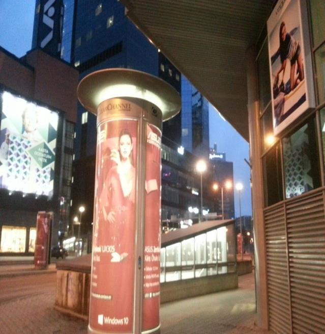
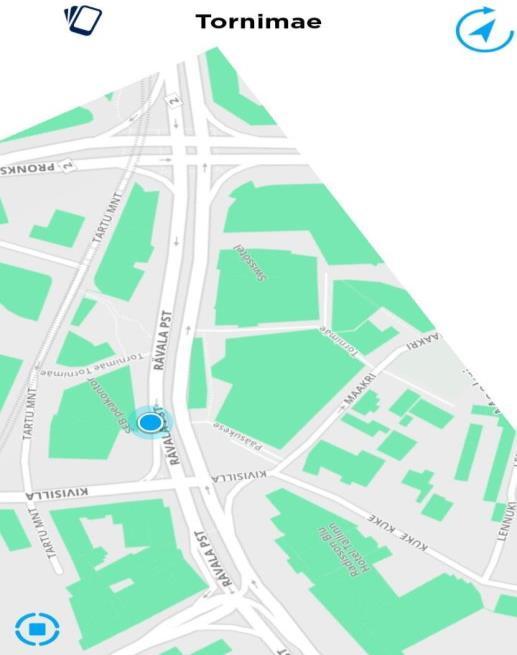
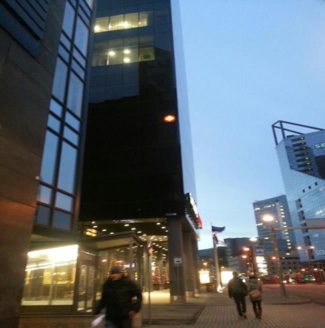
35 4. Experiments with GPS-Independent Outdoor Positioning System, Tallinn 4.1. Experiment with GPS-Independent Outdoor Positioning System, Tallinn: On Foot After the success attained in the first experiment, IndoorAtlas had had to be tried for Outdoor applications for the main purpose of the project. As mentioned before, IndoorAtlas uses the anomalies and fluctuations of ambient magnetic field (especially the magnetic field of Earth) which is caused by the reinforced steel structure and the building materials of buildings. In the light of this knowledge, the second research question was needed to be tested: Could the anomalies and fluctuations of the ambient magnetic field, which is the base of the working principle of IndoorAtlas, be beneficial and useful for GPS- Independent Outdoor Positioning? The motivation behind this step of the project and the experiment was the idea of that there are enough steel and building materials under the roads. Like the corridors and the halls of buildings, in the same way, the outdoor roads can be magnetically fingerprinted since there is enough ambient magnetic field outdoor (especially the magnetic field of Earth). For this experiment, a busy and central location which is surrounded by big towers and buildings that have reinforced steel structures was chosen. This location was Tornimäe, Rävala Puiestee (Avenue), Tallinn, Estonia. The main objective of this experiment creating a model map for GPS-Independent Outdoor Positioning System in a pilot area. The steps which were supposed to be taken were the same as the indoor application. In the previous experiment, similarly, a map of the location was required. In the outdoor application, the floor plans of the mall were used. In this experiment, the actual maps of the roads were necessary. To achieve this issue, IndoorAtlas global map itself was used. An image of the pilot area was 35

36 taken from the global map, then it is applied to the global map itself; just like the floor plan of the mall was applied onto the location of the mall on the global map. Figure 15. Floor plan of Tornimäe The same process as the indoor application was followed in this outdoor application as well. First, main roads were passed on foot. Since it is planned as usable for pedestrians; sidewalks and crosswalks were passed and mapped. Then, after the map was generated and paths were recorded, test paths were prepared. Almost all the road was walked again to create a map with a better accuracy. As can be seen from the figures above, the main roads in Tornimäe, around SEB Pank Main Branch, Stockmann AS Kaubamaja (Mall), Swissôtel Tallinn, Radisson Blu Sky Hotel Tallinn, were mapped for a pilot project. This area is one of the central locations of Tallinn, so, from this point of view, this experiment was going to be useful and helpful to see if this system is suitable and usable for outdoor positioning or not. Following figures show the result of the experiment. As can be seen from these figures, this experiment was successful, and the results show that IndoorAtlas could achieve GPS- Independent Outdoor Positioning project by using anomaly map of ambient magnetic field caused by the concentrated structure of roads and the surrounding buildings. 36

37 (a) (b) Figure 16. Path records and test paths for on foot outdoor application With the success attained in this step of the experiment, the way for the GPS-Independent Outdoor Positioning project became wide open, since this test showed that IndoorAtlas can use the effects of the outdoor materials over, especially, the magnetic field of Earth. These figures and images show that the experiment was successful and accuracy of IndoorAtlas, especially around high and steel-structured buildings is around a few meters. However, this was not the final step for the project. This step was rather instructive since it showed that IndoorAtlas is usable with the outdoor ambient magnetic field, but, besides this step, outdoor usage of IndoorAtlas had to be tested in a vehicle. The next step of the project was about this experiment. 37
 (d)")
38 (a) (b) (c) (d) 38
 Figure 17.")


39 (e) (f) (g) (h) Figure 17. The results of outdoor positioning test in Tornimäe 39
40 4.2. Experiment with GPS-Independent Outdoor Positioning System, Tallinn: By Vehicle Until this stage of the project, IndoorAtlas was tried indoor, to see and understand its working principle, then it was tried outdoor, to see if the working principle is suitable for outside or not. The second experiment, the outdoor application was successful and accuracy of the system was a few meters. Yet, the main and the most important point is to develop this system as a car navigation system, since the number of people who use their cell phones for GPS navigation in the United States was 66.3 Million by the year 2012 [16] and, volume of carnavigation systems by category worldwide by the year 2012 was 230 Million [17]. These statistics show that there is a huge volume of usage of GPS Systems in cars. In the light of these facts, it was a necessary to test the system for vehicles as well. The test with a vehicle might result differently. Since, as mentioned before, IndoorAtlas uses metal fluctuations of the ambient magnetic field. In this case, the cage construction and steel structure of a vehicle may give rise to different results and accuracy values. From this point of view, it can be considered that it is possible to observe different accuracy and precision values in this part of the experiment. Different accuracy values can negatively affect the usability of the whole project unless it is negligible. There might be several reasons for this situation: Recording of the paths will be conducted while in a moving vehicle. Since this movement would be faster that movement of a person, getting data samples for the software might be harder Since the recording operation of the paths will be processed in a vehicle, the cage construction and steel structure of a car may affect the result. After the paths are recorded, the map probably will be used in a different vehicle. Basically all the vehicles, roughly, have similar shapes. However, small differences between metal structures of different vehicles might result in different accuracy values. Under these circumstances, it was possible to observe some differences and potential problems. However, these differences might be negligible. 40

41 In the light of these predictions, the Vehicle Application of GPS-Independent Outdoor Positioning System was started. For this experiment, it would have been a good decision to prefer a frequently-used vehicle by public. Clearly, public transportation would have been the best choice for this test to see if the system works inside of a vehicle or not. For this experiment, one of the bus lines of Tallinn, number 40 (Viru Keskus Pelguranna) was chosen. This bus line has many stops, yet, the test was performed between Harjapea and Viru Keskus stops. The bus passes Telliskivi, Tehnika, Vabaduse Valjak and Estonia regions between these stops. Besides, the test was performed for both directions (Harjapea Viru Keskus, Viru Keskus Harjapea). As the previous experiment, a map of the location was required. Similarly, IndoorAtlas global map itself was used and an image of the route which was passed was taken from the global map, then it was applied to the global map itself. Figure 18 Floor plan of Harjapea - Viru Keskus line The bus 40 was taken from Harjapea stop, and, the map was started to be created part by part, along the road. All the road was recorded from Harjapea to Viru Keskus and from Viru Keskus to Harjapea. Then, the same road was passed again by another bus, to record the test maps to provide better accuracy to the system. Similarly, the same road and the same route was passed by the bus. 41


42 After all the data was recorded, another bus of line 40 was taken from Harjapea to observe the results. As the results of the experiment, the accuracy of the blue dot was just a bit less than other experiments. As mentioned before, this was a result of that the bus is normally faster than a moving pedestrian. Besides, the map and the location of the application was huge when it is compared with the other experiments. These factors can cause the lack of accuracy, however, in big maps such as this one which was prepared for big areas, (a) (b) Figure 19. Path records and test paths for outdoor application by vehicle After all the data was recorded, another bus of line 40 was taken from Harjapea to observe the results. As the results of the experiment, the accuracy of the blue dot was just a bit less than other experiments. As mentioned before, this was a result of that the bus is normally faster than a moving pedestrian. Besides, the map and the location of the application was huge when it is compared with the other experiments. These factors can cause the lack of accuracy, however, in big maps such as this one which was prepared for big areas, this accuracy error can be neglected. The Department of Defense of United States of America states that the GPS technology provides 4 meters of accuracy with the new improvements [18]. Additionally, as IndootAtlas Inc. Company claims, IndoorAtlas offers 3 meters of accuracy on indoor positioning systems [19]. As can be seen from the results of the experiment, the 42
 (b) (c) Figure 20.")
43 usage of the GPS-Independent Outdoor Positioning System provides an accuracy level around 6-8 meters. Besides its potential as a developable application, GPS-Independent Outdoor Positioning System also offers a fair accuracy level. (a) (b) (c) Figure 20. The results of the outdoor test in Harjapea - Viru Keskus Line With this experiment, it was observed that IndoorAtlas is usable for GPS-Independent Outdoor Positioning System Project. The working principle IndoorAtlas has, can be benefited from, to achieve GPS-Independent Outdoor Positioning System. Further in the project, the outdoor applications were expanded with the map which was made for Istanbul. Additionally, a unique mobile application for Android Platform that is based on IndoorAtlas was developed. Up to now, the main focus of the project, GPS-Independent Outdoor Positioning System was examined and tried in different places with different methods. IndoorAtlas, the service (PaaS) which has been developed for indoor positioning where GPS Systems are not available, was first tried indoor, then its working principle was deeply examined and understood. After this step, in accordance with the working principle, the system was adapted for outdoor and it was tested in a different location in Tallinn, Estonia. The test in Tallinn was conducted for 43
44 both pedestrians (on foot) and as a car GPS system. These tests were rather successful. IndoorAtlas, which has been produced for basically indoor positioning and navigation, achieved the GPS-Independent Outdoor System Project for both methods. From this point on, there were two more necessary and critical tasks left to be completed. First, GPS-Independent Outdoor Positioning System was going to be applied to Turkey, Istanbul. Secondly, a mobile application which is based on IndoorAtlas for Android Platform was going to be developed. The main focus of the mobile application was going to be connected to the pre-generated GPS-Independent Outdoor Positioning maps and let the users benefit from them in chosen cities and/or regions. 44
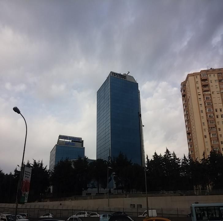
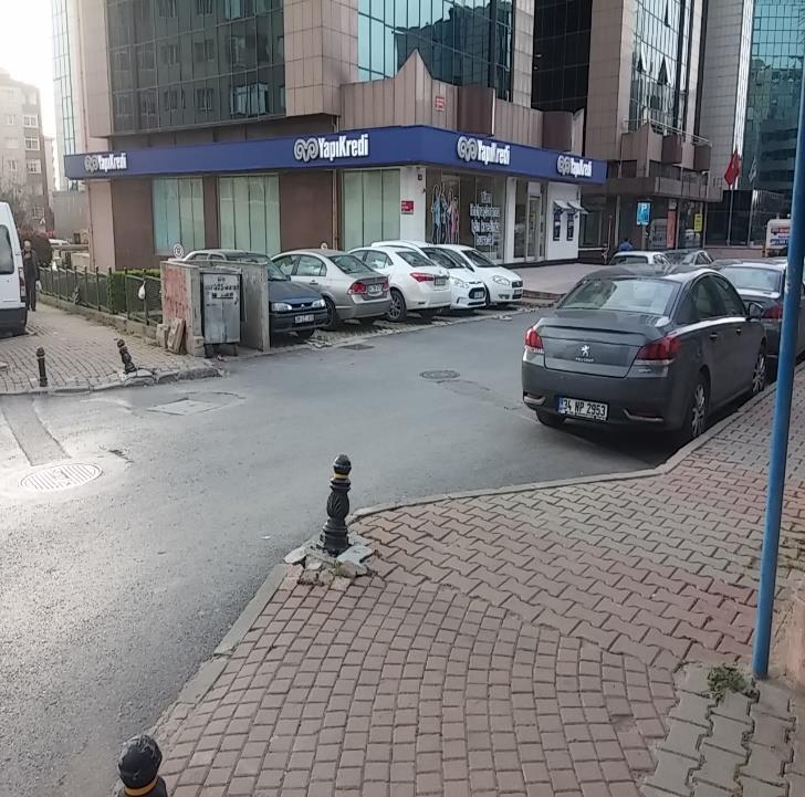
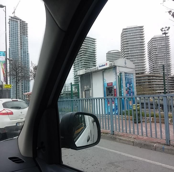
45 5. Experiments with GPS-Independent Outdoor Positioning System, İstanbul 5.1. Experiment with GPS-Independent Outdoor Positioning System, İstanbul: On Foot The last but not the least application of the project was going to be applied to Istanbul, Turkey. The first step of this application was preparing the system for pedestrians, and then a map for vehicles was prepared, similar with Tallinn. For the on foot part of the project, for better results, one of the busy and central locations of the city was decided to be chosen. The pilot area for his experiment was Bostancı, İstanbul, Turkey. The area is surrounded by high towers and huge trade centers. Besides, there is a highway which crosses by the route of the map. Also, there is a big campus of a public hospital and private university in the immediate vicinity. In the light of these factors, this can be stated that this area is a busy and a frequently-used neighborhood and it was definitely suitable for this experiment. The steps which were supposed to be taken were the same as the previous steps and experiments of the project. Similarly, the whole road was needed to be crossed through and through, with all important side streets. While walking down the road, the sidewalks should were used since this map was going to be prepared for pedestrians. Sidewalks on the both sides of the each part of the road were crossed. The test was started to be performed from the broadside of the highway. Since one of the sides of the road which passes by the highway has no sidewalk, due to the highway, only one side of the main road was crossed through. There were the headquarters of some banks and big companies by these side streets and the main road. 45

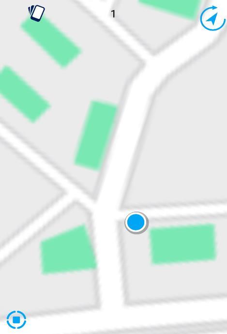
46 Similarly, a screenshot of the region from the global map of IndoorAtlas, which is the object of the test, was used as the floorplan of the test. Figure 21. Floor plan of outdoor test Classically, with the respect to the working principle of IndoorAtlas, all the sidewalks in route were crossed part by part with a constant speed and the route was magnetically fingerprinted. After mapping phase is done, test paths were created to provide the system with a better accuracy. To achieve adding test paths part, some random parts of the route were crossed again. After all these processes, the map which was prepared in İstanbul, Bostancı for pedestrians was ready to be tested and used. The results of the experiment can be observed from the figures below: As can be seen from the figures and images above, the results and the accuracy of the system was extremely successful. So far in the project, this was the experiment which was most successful and accurate and works perfectly. The accuracy of the system was less than 1 meter. 46
 (d)")
47 (a) (b) (c) (d) 47

48 (e) (f) Figure 22. The results of outdoor positioning test in Bostancı After the observation of the results, this can be stated that these good results and almost perfect rate of accuracy are related to magnetic field distorting ability of the area which is the object of the experiment. In this area, there are too many Wi-Fi and other signals besides the magnetic field of Earth. Additionally, there are a remarkable amount of big buildings and towers which have reinforced steel structure and different types of building materials. The intensity of steel structures and building materials of the buildings causes more anomalies and fluctuations of the ambient magnetic field. Thus, magnetically fingerprinting of the paths could be performed better. Surely, the experiences which were gained during the previous experiments also have a big part in this success in the experiment. Even the methods which are used in the experiments are mostly similar, with the experiences gained, mapping phase and recording of the anomalies of the ambient magnetic field gets better and more accurate. After this experiment and the success which can be observed from the accuracy rate of the positioning, the next application of the GPS-Independent Outdoor Application was going to be conducted. 48
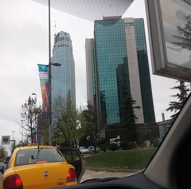
49 5.2. Experiment with GPS-Independent Outdoor Positioning System, Istanbul: By Vehicle Istanbul is the most crowded city of Turkey with more than 14 Million inhabitants and it is one of the biggest metropolises of the world. Istanbul has many trade centers and a transfer location between Europe and Asia. This is a fact that the number of motor vehicles in Turkey is almost 19 Million [20] while the total number of motor vehicles in Istanbul is almost 3.5 Million, [21] which is almost 20% of the total number, by the year These statistics and numbers are clear evidence of that inhabitant of Istanbul are commonly use personal motor vehicles. Thus, this situation gives rise to the need for positioning systems. From this point of view, it was necessary to develop and test the GPS-Independent Outdoor Positioning System for Istanbul, as available for vehicles as well. As the previous tests, this last test was also going to be conducted in a busy and central location of Istanbul. For this purpose, one of the most centers of Istanbul, Levent District was chosen. In this pilot area, there are two main highways which connect all parts of the city with each other and linking roads for Istanbul Bosphorus Bridge, Anatolian Side of Istanbul and other important districts of the city. It can be said that this area just like the heart of the city. Experimenting the GPS-Independent Outdoor Positioning Systems for Vehicles in such central district of such a big city was going to be a rather instructive and important. As stated before, there are too many important roads and highways around this pilot area. This situation makes the area rather ideal for this application. The procedures which were supposed to be followed were same again. Similarly, a screenshot of the location from the global map of IndoorAtlas was taken and used as the floor plan. The tests and recording of the anomalies of the ambient magnetic field were performed by personal car. Almost all main roads and highways around the route were crossed thoroughly. Especially, the roads which surround the huge and steel structured buildings were chosen to be crossed and mapped. The magnetic characteristic of the pilot region was recorded and the 49

50 area was magnetically fingerprinted. The test paths were also added to achieve better accuracy. Figure 23. Path records for outdoor application in İstanbul by vehicle As experienced in previous experiments, the map was ready to be used and positioning process after the recording of anomalies of the ambient magnetic field in the mapping phase. With the help of steel structures of the buildings and building materials of the roads, intense metal fluctuations of ambient magnetic field, good results were observed as can be seen from the figures and images below: These results show that IndoorAtlas is rather helpful and useful to develop GPS-Independent Outdoor Positioning System. In all the experiments which were performed outdoor were successful and accuracy of the system was a 1-2 meter and for the very big routes 3-4 meter which are negligible values when it is considered that this system has a developable infrastructure. 50
 (d)")
51 (a) (b) (c) (d) 51


52 (e) (f) (g) (h) Figure 24. The results of outdoor positioning test in Levent 52
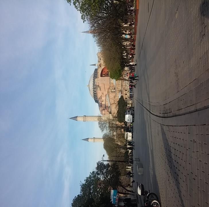
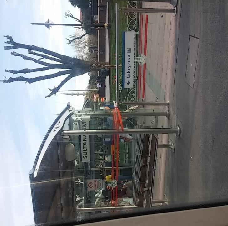
53 5.3. Experiment with GPS-Independent Outdoor Positioning System, Istanbul: Combined The last two experiments were conducted in a popular and a huge city. The pilot areas were the trade centers of Istanbul. Thousands of people visit these areas to go to their offices, or to the Anatolian or European side of the city. Besides the trade centers and huge malls, Istanbul also has too many different historical and touristic locations which are visited by many people every day. Many Turkish and foreign tourists visit historical and natural places in Istanbul. One of the most popular touristic destinations of Istanbul is Sultanahmet Square and its outskirt neighborhood. There are many historical buildings and monuments such as Çemberlitaş (Column of Constantine), Sultanahmet Mosque, Hagia Sophia Museum, Yerebatan Sarnıcı (Basilica Cistern), Archeology Museum, Kapalı Çarşı (Grand Bazaar) Gülhane Park and Topkapı Palace. There are many streets for pedestrians around these places, and the main road for vehicles with a tram line which crosses this area. As can be seen, it is an important and central location where GPS-Independent Outdoor Position System could be useful. So far, the system was tried for pedestrians and vehicles separately. In this region, the public transportation, tram line, could be used to test the system by a vehicle and the streets around the area could be mapped by walk. Thus, both methods were going to be combined in this experiment. The figure below was used as the floor plan of this experiment. The mains road which is shown with the red line is used by cars, and it is the route of the tram line. In the vehicle part of the experiment, the public tram was used. This route is the most popular part of the tram line among the tourists. The side streets and sidewalks which are shown with blue lines are the popular routes of tourists to visit all the important places around the neighborhood. In walking part of the experiment, that route was used. 53

54 Figure 25. The mapped routes on foot and by vehicle on the last application in Sultanahmet As the previous experiments, the roads were crossed and magnetic distortions were recorded in this experiment as well. Test paths were also added to this map too to achieve better accuracy levels. Differently from the other experiments, the Flight Mode was activated during the experiment. First, the Flight Mode was tried to be activated on mapping phase. Once the floor plan is downloaded from the server, IndoorAtlas does not require to be connected neither to a Wi- Fi hotspot nor mobile internet network for mapping phase. However, as observed in this experiment, IndoorAtlas needs the Wi-Fi scanning feature to be activated to scan ambient Wi-Fi signals and their anomalies to create a map with better accuracy. Thus, even flight mode is activated and GSM network and mobile internet are deactivated, Wi-Fi scanning mode must be enabled. In positioning phase, Flight Mode was again tried to be activated. Once the paths which were created for positioning were downloaded from servers, the Flight Mode was activated. The positioning was successful since, as can be seen from the Developer Kit SDK Files which IndoorAtlas releases, the calculations of the anomalies of the magnetic field are performed locally on the mobile device, independent from internet connection and servers. After mapping phase, the maps were ready to be used. GPS-Independent Outdoor Positioning System is designed as useful in all circumstances, for both pedestrians and vehicles. This situation gives rise to the necessity of that all maps must 54


55 be created as available for both types of users. From this point of view, the last combined experiment was rather important to conduct since it showed that it is possible to create maps for both users at the same time, and, even in this case, the system works with the same accuracy level. (a) (b) (c) (d) 55
 (h)")
56 (e) (f) (g) (h) 56

57 (i) (j) Figure 26. The results of the combined outdoor positioning test in Sultanahmet This last experiment was the last application of IndoorAtlas, and, the most important cases were tested in all experiments conducted so far, to see how GPS-Independent Outdoor Positioning System works and if it is a valid solution to achieve the main target. Since the maps were ready to be used, as the last experiment was performed finally, the last part of the project could be conducted. As the last part, a mobile app for Android Platform which contains the maps that were created for the project and the data that is gathered from different sensors from the mobile device was developed. 57
58 6. Conclusion of Experiments After all the experiments were performed, it was rather easy to see and compare the results of the accuracy levels of the tests. As can be seen from the results below, the error of accuracy decreases when there are more steel-structured buildings since the ambient magnetic field is distorted more and these locations have more intense magnetic characters. In the following table, all maximum, minimum and average accuracy error rates are given in meters. Maximum Minimum Average Tallinn: On Foot Tallinn: By Vehicle Istanbul: On Foot Istanbul: By Vehicle Istanbul: Combined Table 1. Error rates of accuracy 58
59 7. Find Me Tallinn İstanbul: The Mobile App for Android Platform Once a map is created via IndoorAtlas, for any venue, the map is available to be used on servers of IndoorAtlas. The users can see the maps via Web UI of IndoorAtlas, and can use the maps for positioning via the mobile app of IndoorAtlas. However, once a user logs into the system of IndoorAtlas, all the maps which were created by all IndoorAtlas users are available to be used. All of the usable and properly created ones of these maps are indoor maps, and, for the one who wants to use GPS-Independent Outdoor Positioning System, this situation would cause confusions. Starting this point of view, there was a need to develop a mobile app to gather up all the maps which were generated for GPS-Independent Outdoor Positioning System. This app was going to be specialized for GPS-Independent Outdoor Positioning System. The app was planned as to have two different choices for both cities since the experiments were conducted in two different cities. Once the user chooses the city, the app asks for if s/he is a pedestrian or going to use it for a vehicle. After this selection, the app asks for is the user wants to see his/her location on Google Maps, or on the image of the floor plan. After this last selection, the requested map is pulled from the servers of IndoorAtlas and presented to the user. During these operations, there is no need to log into the system since the logging in is only needed while creating maps. Users do not need to log into the system to use the maps. The name of the application which was developed by the author is; Find Me [22]. Each map has its own IDs. There are 3 different IDs which are used to determine a map. These IDs are; FloorplanID, FloorID, and VenueID. 59


60 Figure 27. Find Me logo Figure 28. FloorplanID, FloorID, and VenueID of the map that was created for İstanbul, Bostancı As the IndoorAtlas SDK provides, the maps which are desired to be used can be defined and called from the server by their FloorplanID. The code part which calls the maps to Find Me application can be seen in Appendix 1. Once the map is called by its FloorplanID, its floor plan and the recorded magnetic distortion information which belongs to the called map are also gotten. Therefore, with this information gathered, positioning could be possible. IndoorAtlas SDK provides different types of layout for positioning screen. After the tests conducted, two most useful layouts were chosen and applied into Find Me application. One of these layouts is Google Maps layout. Per this layout, while positioning process, the position of the user is shown on Google Maps. Once this layout is applied and chosen from the menu, user sees the global map, then, it zooms to the region where the chosen map belongs to. The Blue Pin of Google Maps shows the current location of the user. The other type of layout is image layout. Basically, as similar with the IndoorAtlas application itself, the system shows the current location of the user on the Floor Plan image. Since 60
 (b) (c) Figure 29.")


61 this layout is familiar from IndoorAtlas and it is the base of it, this layout is also applied into Find Me as a second option. These layouts and choice buttons for these layouts on the menu can be seen below. (a) (b) (c) Figure 29. Layout selection and different layout screens of Find Me App These layouts are connected to these menu buttons by the code part which is presented in Appendix 2. As the experiments conducted, different maps were created for both pedestrians and vehicles. This was to see different results on different applications. Since there is such a distinction in the maps and conducted experiments, there was a need to distinguish these two different concepts in Find Me application as well. To achieve this, two more buttons were designed. Once the user chooses if s/he is going to use the system as a pedestrian or by a vehicle, the appropriate map is called with layout choice. For example, when someone is in Istanbul and wants to use the system by a vehicle, s/he should choose Istanbul and vehicle choices. Since the experiment which was conducted by a vehicle in Istanbul was in Levent district, the Find Me app will serve the layout choices for Istanbul, Levent map. Or, if the user in Tallinn and want to use the system as a pedestrian, s/he should choose Tallinn from the main menu, then 61

62 the pedestrian choice from the next menu. On the 3 rd menu, the app will be serving the layout choices for Tornimäe, Rävala Puiestee, Tallinn. Since there are 3 different concept choices for Istanbul; by vehicle, pedestrian and mixed, 3 different buttons were designed. The operation of calling the right map with clicking on a button was achieved with the following code part. if (stcity == "TALLINN" && ststatus == "VEHICLE") { stcurrentmapid = stmapidtallinnvehicle; } else if (stcity == "TALLINN" && ststatus == "WALK") { stcurrentmapid = stmapidtallinnwalk; } else if (stcity == "ISTANBUL" && ststatus == "VEHICLE") { stcurrentmapid = stmapidistanbulvehicle; Figure 30. Menu buttons and maps connection codes (a) (b) Figure 31. Map selection screen to use the Find Me app on foot or by vehicle As can be understood, on the main page of the application, there was a need to design buttons to let the user choose the city where the system will be used. Since the system is available in only two cities right now, two different buttons were designed for both Tallinn and Istanbul. After the city is chosen, available concepts and layout for positioning would be available for the user. 62

63 With the functions and buttons mentioned above, Find Me application have the ability to perform GPS-Independent Outdoor Positioning for the created maps. As will be mentioned in further chapters, Find Me application is developable with new and wider maps. For now, Find Me will be serving only the maps which were created within the project. Besides its general structure and function, Find Me was designed to show the data which is gathered from sensors. With the help of three different sensors of the device, different information regarding the device s position and movements can be gathered. As mentioned before, three main sensors, accelerometer, gyroscope and compass in the device are used to achieve positioning which based on the anomalies and distortions of the ambient magnetic field. Figure 32. City selection screen of Find Me App Therefore, making the sensor data available for the user could be a good feature for the application. The sensor data is collected by following code public void onsensorchanged(sensorevent event) { if (event.sensor.gettype() == Sensor.TYPE_ACCELEROMETER) { float x = event.values[0]; float y = event.values[1]; float z = event.values[2]; 63
 == Sensor.TYPE_ORIENTATION){ } else if (event.sensor.gettype() == Sensor.TYPE_MAGNETIC_FIELD) Figure 33.")
64 txtxvalue.settext(string.valueof(x)); txtyvalue.settext(string.valueof(y)); txtzvalue.settext(string.valueof(z)); { } else if (event.sensor.gettype() == Sensor.TYPE_GYROSCOPE){ } else if (event.sensor.gettype() == Sensor.TYPE_ORIENTATION){ } else if (event.sensor.gettype() == Sensor.TYPE_MAGNETIC_FIELD) Figure 33. Sensor data code After the data is collected from the sensors, these data were grouped and served under Advanced menu as can be seen from the figure below. Figure 34. Sensor data screen of Find Me App The first group of data shows the Accelerometer Data. X, Y, and Z are the axes and the numbers across these axes are the acceleration values of the movement of the device on these axes. The second group basically show the information which is collected from the gyroscope. The third group on the sensor data section shows the basic compass data. Azimuth is the angular value on the z axis and this value basically shows the direction of the device. On the direction of the North, the azimuth value is 0 while this value is 180 on the direction to South and it changes between 0 and The Pitch is the value of altitude angle of the 64


65 device on x axis and it varies between -180 and The Roll is the value of the tilt of the device on the y axis and it changes between -90 and +90. The fourth and the last group of sensor data is the 3-Dimensional ambient magnetic field and all the values in µt. This data is gathered from the magnetometer which the device has, and it is the raw data of the compass data above. The functional features of Find Me app designed as mentioned above. Besides these functions, a page named as Credits was implemented into the app. In this page, the aim and the developer of the app were told. Additionally, the splash screen of the can be seen below. (a) (b) Figure 35. Credits and splash screens of Find Me App 65
Range Sensing strategies
 Range Sensing strategies Active range sensors Ultrasound Laser range sensor Slides adopted from Siegwart and Nourbakhsh 4.1.6 Range Sensors (time of flight) (1) Large range distance measurement -> called
Hardware-free Indoor Navigation for Smartphones
 Hardware-free Indoor Navigation for Smartphones 1 Navigation product line 1996-2015 1996 1998 RTK OTF solution with accuracy 1 cm 8-channel software GPS receiver 2004 2007 Program prototype of Super-sensitive
Gesture Identification Using Sensors Future of Interaction with Smart Phones Mr. Pratik Parmar 1 1 Department of Computer engineering, CTIDS
 Gesture Identification Using Sensors Future of Interaction with Smart Phones Mr. Pratik Parmar 1 1 Department of Computer engineering, CTIDS Abstract Over the years from entertainment to gaming market,
Senion IPS 101. An introduction to Indoor Positioning Systems
 Senion IPS 101 An introduction to Indoor Positioning Systems INTRODUCTION Indoor Positioning 101 What is Indoor Positioning Systems? 3 Where IPS is used 4 How does it work? 6 Diverse Radio Environments
INDOOR LOCATION SENSING AMBIENT MAGNETIC FIELD. Jaewoo Chung
 INDOOR LOCATION SENSING AMBIENT MAGNETIC FIELD Jaewoo Chung Positioning System INTRODUCTION Indoor positioning system using magnetic field as location reference Magnetic field inside building? Heading
Introduction to Mobile Sensing Technology
 Introduction to Mobile Sensing Technology Kleomenis Katevas k.katevas@qmul.ac.uk https://minoskt.github.io Image by CRCA / CNRS / University of Toulouse In this talk What is Mobile Sensing? Sensor data,
CENG 5931 HW 5 Mobile Robotics Due March 5. Sensors for Mobile Robots
 CENG 5931 HW 5 Mobile Robotics Due March 5 Sensors for Mobile Robots Dr. T. L. Harman: 281 283-3774 Office D104 For reports: Read HomeworkEssayRequirements on the web site and follow instructions which
ANDROID APPS DEVELOPMENT FOR MOBILE GAME
 ANDROID APPS DEVELOPMENT FOR MOBILE GAME Lecture 5: Sensor and Location Sensor Overview Most Android-powered devices have built-in sensors that measure motion, orientation, and various environmental conditions.
Indoor localization using NFC and mobile sensor data corrected using neural net
 Proceedings of the 9 th International Conference on Applied Informatics Eger, Hungary, January 29 February 1, 2014. Vol. 2. pp. 163 169 doi: 10.14794/ICAI.9.2014.2.163 Indoor localization using NFC and
MOBILE COMPUTING 1/29/18. Cellular Positioning: Cell ID. Cellular Positioning - Cell ID with TA. CSE 40814/60814 Spring 2018
 MOBILE COMPUTING CSE 40814/60814 Spring 2018 Cellular Positioning: Cell ID Open-source database of cell IDs: opencellid.org Cellular Positioning - Cell ID with TA TA: Timing Advance (time a signal takes
Indoor Positioning 101 TECHNICAL)WHITEPAPER) SenionLab)AB) Teknikringen)7) 583)30)Linköping)Sweden)
WHITEPAPER) SenionLab)AB) Teknikringen)7) 583)30)Linköping)Sweden)") Indoor Positioning 101 TECHNICAL)WHITEPAPER) SenionLab)AB) Teknikringen)7) 583)30)Linköping)Sweden) TechnicalWhitepaper)) Satellite-based GPS positioning systems provide users with the position of their
Indoor Positioning 101 TECHNICAL)WHITEPAPER) SenionLab)AB) Teknikringen)7) 583)30)Linköping)Sweden) TechnicalWhitepaper)) Satellite-based GPS positioning systems provide users with the position of their
INDOOR LOCATION SENSING USING GEO-MAGNETISM
 INDOOR LOCATION SENSING USING GEO-MAGNETISM Jaewoo Chung 1, Matt Donahoe 1, Chris Schmandt 1, Ig-Jae Kim 1, Pedram Razavai 2, Micaela Wiseman 2 MIT Media Laboratory 20 Ames St. Cambridge, MA 02139 1 {jaewoo,
Sponsored by. Nisarg Kothari Carnegie Mellon University April 26, 2011
 Sponsored by Nisarg Kothari Carnegie Mellon University April 26, 2011 Motivation Why indoor localization? Navigating malls, airports, office buildings Museum tours, context aware apps Augmented reality
Aerospace Sensor Suite
 Aerospace Sensor Suite ECE 1778 Creative Applications for Mobile Devices Final Report prepared for Dr. Jonathon Rose April 12 th 2011 Word count: 2351 + 490 (Apper Context) Jin Hyouk (Paul) Choi: 998495640
IoT Wi-Fi- based Indoor Positioning System Using Smartphones
 IoT Wi-Fi- based Indoor Positioning System Using Smartphones Author: Suyash Gupta Abstract The demand for Indoor Location Based Services (LBS) is increasing over the past years as smartphone market expands.
IoT. Indoor Positioning with BLE Beacons. Author: Uday Agarwal
 IoT Indoor Positioning with BLE Beacons Author: Uday Agarwal Contents Introduction 1 Bluetooth Low Energy and RSSI 2 Factors Affecting RSSI 3 Distance Calculation 4 Approach to Indoor Positioning 5 Zone
Sensors for orientation and control of satellites and space probes
 Sensors for orientation and control of satellites and space probes Ing. Ondrej Závodský GOSPACE s.r.o. ESA Contract No. 4000117400/16NL/NDe Specialized lectures Content 1) How to determine the orientation
Navigation problem. Jussi Suomela
 Navigation problem Define internal navigation sensors for a ground robot with car type kinematics (4 wheels + ackerman steering + rear wheel drive) Sensors? Where? Why? ~ 15-20 min. Describe your system
Indoor Positioning by the Fusion of Wireless Metrics and Sensors
 Indoor Positioning by the Fusion of Wireless Metrics and Sensors Asst. Prof. Dr. Özgür TAMER Dokuz Eylül University Electrical and Electronics Eng. Dept Indoor Positioning Indoor positioning systems (IPS)
Indoor navigation with smartphones
 Indoor navigation with smartphones REinEU2016 Conference September 22 2016 PAVEL DAVIDSON Outline Indoor navigation system for smartphone: goals and requirements WiFi based positioning Application of BLE
OughtToPilot. Project Report of Submission PC128 to 2008 Propeller Design Contest. Jason Edelberg
 OughtToPilot Project Report of Submission PC128 to 2008 Propeller Design Contest Jason Edelberg Table of Contents Project Number.. 3 Project Description.. 4 Schematic 5 Source Code. Attached Separately
Downwelling Light Sensor 2 (DLS 2) Integration Guide
 Integration Guide") Downwelling Light Sensor 2 (DLS 2) Integration Guide Revision 01, November 2018 Seattle, WA 2018 MicaSense, Inc. Page 1 of 17 Table of Contents Overview and Scope 3 Measurements and Attachment Points 4
Downwelling Light Sensor 2 (DLS 2) Integration Guide Revision 01, November 2018 Seattle, WA 2018 MicaSense, Inc. Page 1 of 17 Table of Contents Overview and Scope 3 Measurements and Attachment Points 4
Ubiquitous Positioning: A Pipe Dream or Reality?
 Ubiquitous Positioning: A Pipe Dream or Reality? Professor Terry Moore The University of What is Ubiquitous Positioning? Multi-, low-cost and robust positioning Based on single or multiple users Different
Agenda Motivation Systems and Sensors Algorithms Implementation Conclusion & Outlook
 Overview of Current Indoor Navigation Techniques and Implementation Studies FIG ww 2011 - Marrakech and Christian Lukianto HafenCity University Hamburg 21 May 2011 1 Agenda Motivation Systems and Sensors
Robust Positioning for Urban Traffic
 Robust Positioning for Urban Traffic Motivations and Activity plan for the WG 4.1.4 Dr. Laura Ruotsalainen Research Manager, Department of Navigation and positioning Finnish Geospatial Research Institute
Improved Pedestrian Navigation Based on Drift-Reduced NavChip MEMS IMU
 Improved Pedestrian Navigation Based on Drift-Reduced NavChip MEMS IMU Eric Foxlin Aug. 3, 2009 WPI Workshop on Precision Indoor Personnel Location and Tracking for Emergency Responders Outline Summary
Attitude and Heading Reference Systems
 Attitude and Heading Reference Systems FY-AHRS-2000B Installation Instructions V1.0 Guilin FeiYu Electronic Technology Co., Ltd Addr: Rm. B305,Innovation Building, Information Industry Park,ChaoYang Road,Qi
Indoor Floorplan with WiFi Coverage Map Android Application
 Indoor Floorplan with WiFi Coverage Map Android Application Zeying Xin Electrical Engineering and Computer Sciences University of California at Berkeley Technical Report No. UCB/EECS-2013-114 http://www.eecs.berkeley.edu/pubs/techrpts/2013/eecs-2013-114.html
SPEEDBOX Technical Datasheet
 SPEEDBOX Technical Datasheet Race Technology Limited, 2008 Version 1.1 1. Introduction... 3 1.1. Product Overview... 3 1.2. Applications... 3 1.3. Standard Features... 3 2. Port / Connector details...
Analysis of Tumbling Motions by Combining Telemetry Data and Radio Signal
 SSC18-WKX-01 Analysis of Tumbling Motions by Combining Telemetry Data and Radio Signal Ming-Xian Huang, Ming-Yang Hong, Jyh-Ching Juang Department of Electrical Engineering, National Cheng Kung University,
Utility of Sensor Fusion of GPS and Motion Sensor in Android Devices In GPS- Deprived Environment
 Utility of Sensor Fusion of GPS and Motion Sensor in Android Devices In GPS- Deprived Environment Amrit Karmacharya1 1 Land Management Training Center Bakhundol, Dhulikhel, Kavre, Nepal Tel:- +977-9841285489
NavShoe Pedestrian Inertial Navigation Technology Brief
 NavShoe Pedestrian Inertial Navigation Technology Brief Eric Foxlin Aug. 8, 2006 WPI Workshop on Precision Indoor Personnel Location and Tracking for Emergency Responders The Problem GPS doesn t work indoors
PS4 Remote Play review: No Farewell to Arms, but a Moveable Feast
 PS4 Remote Play review: No Farewell to Arms, but a Moveable Feast PlayStation 4 is the most fantastic console in the Universe! Why do we say so? Because PS4 is the most popular gaming console ever. Accordingly
Pedestrian Navigation System Using. Shoe-mounted INS. By Yan Li. A thesis submitted for the degree of Master of Engineering (Research)
") Pedestrian Navigation System Using Shoe-mounted INS By Yan Li A thesis submitted for the degree of Master of Engineering (Research) Faculty of Engineering and Information Technology University of Technology,
Pedestrian Navigation System Using Shoe-mounted INS By Yan Li A thesis submitted for the degree of Master of Engineering (Research) Faculty of Engineering and Information Technology University of Technology,
Indoor Positioning System using Magnetic Positioning and BLE beacons
 Indoor Positioning System using Magnetic Positioning and BLE beacons Prof.Manoj.V. Bramhe 1, Jeetendra Gan 2, Nayan Ghodpage 3, Ankit Nawale 4, Gurendra Bahe 5 1Associate Professor & HOD, Dept of Information
BeFitter Apps Manual
 BeFitter Apps Manual Key features The apps BF Hiker, BF Cycle, BF XC Ski and BF Runner have 13 pages. You can toggle through these pages with the previous page and next page function. See the chapter User
Roadblocks for building mobile AR apps
 Roadblocks for building mobile AR apps Jens de Smit, Layar (jens@layar.com) Ronald van der Lingen, Layar (ronald@layar.com) Abstract At Layar we have been developing our reality browser since 2009. Our
Technology Challenges and Opportunities in Indoor Location. Doug Rowitch, Qualcomm, San Diego
 PAGE 1 qctconnect.com Technology Challenges and Opportunities in Indoor Location Doug Rowitch, Qualcomm, San Diego 2 nd Invitational Workshop on Opportunistic RF Localization for Future Directions, Technologies,
A 3D Ubiquitous Multi-Platform Localization and Tracking System for Smartphones. Seyyed Mahmood Jafari Sadeghi
 A 3D Ubiquitous Multi-Platform Localization and Tracking System for Smartphones by Seyyed Mahmood Jafari Sadeghi A thesis submitted in conformity with the requirements for the degree of Doctor of Philosophy
Master Thesis Presentation Future Electric Vehicle on Lego By Karan Savant. Guide: Dr. Kai Huang
 Master Thesis Presentation Future Electric Vehicle on Lego By Karan Savant Guide: Dr. Kai Huang Overview Objective Lego Car Wifi Interface to Lego Car Lego Car FPGA System Android Application Conclusion
INTRODUCTION TO VEHICLE NAVIGATION SYSTEM LECTURE 5.1 SGU 4823 SATELLITE NAVIGATION
 INTRODUCTION TO VEHICLE NAVIGATION SYSTEM LECTURE 5.1 SGU 4823 SATELLITE NAVIGATION AzmiHassan SGU4823 SatNav 2012 1 Navigation Systems Navigation ( Localisation ) may be defined as the process of determining
FLCS V2.1. AHRS, Autopilot, Gyro Stabilized Gimbals Control, Ground Control Station
 AHRS, Autopilot, Gyro Stabilized Gimbals Control, Ground Control Station The platform provides a high performance basis for electromechanical system control. Originally designed for autonomous aerial vehicle
Introduction to Embedded Systems
 Introduction to Embedded Systems Edward A. Lee & Sanjit Seshia UC Berkeley EECS 124 Spring 2008 Copyright 2008, Edward A. Lee & Sanjit Seshia, All rights reserved Lecture 3: Sensors and Actuators Sensors
APP NOTE. Acceleration Sensitivity Characteristics of Quartz Crystal Oscillators
 APP NOTE Acceleration Sensitivity Characteristics of Quartz Crystal Oscillators The resonant frequency of every quartz crystal is affected by acceleration forces. The nature of the effect depends on the
ENHANCEMENTS IN UAV FLIGHT CONTROL AND SENSOR ORIENTATION
 Heinz Jürgen Przybilla Manfred Bäumker, Alexander Zurhorst ENHANCEMENTS IN UAV FLIGHT CONTROL AND SENSOR ORIENTATION Content Introduction Precise Positioning GNSS sensors and software Inertial and augmentation
ANNUAL OF NAVIGATION 16/2010
 ANNUAL OF NAVIGATION 16/2010 STANISŁAW KONATOWSKI, MARCIN DĄBROWSKI, ANDRZEJ PIENIĘŻNY Military University of Technology VEHICLE POSITIONING SYSTEM BASED ON GPS AND AUTONOMIC SENSORS ABSTRACT In many real
SELF-BALANCING MOBILE ROBOT TILTER
 Tomislav Tomašić Andrea Demetlika Prof. dr. sc. Mladen Crneković ISSN xxx-xxxx SELF-BALANCING MOBILE ROBOT TILTER Summary UDC 007.52, 62-523.8 In this project a remote controlled self-balancing mobile
DEMONSTRATION OF ROBOTIC WHEELCHAIR IN FUKUOKA ISLAND-CITY
 DEMONSTRATION OF ROBOTIC WHEELCHAIR IN FUKUOKA ISLAND-CITY Yutaro Fukase fukase@shimz.co.jp Hitoshi Satoh hitoshi_sato@shimz.co.jp Keigo Takeuchi Intelligent Space Project takeuchikeigo@shimz.co.jp Hiroshi
Indoor Positioning with a WLAN Access Point List on a Mobile Device
 Indoor Positioning with a WLAN Access Point List on a Mobile Device Marion Hermersdorf, Nokia Research Center Helsinki, Finland Abstract This paper presents indoor positioning results based on the 802.11
An Improved Version of the Fluxgate Compass Module V. Petrucha
 An Improved Version of the Fluxgate Compass Module V. Petrucha Satellite based navigation systems (GPS) are widely used for ground, air and marine navigation. In the case of a malfunction or satellite
UNIT Explain the radiation from two-wire. Ans: Radiation from Two wire
 UNIT 1 1. Explain the radiation from two-wire. Radiation from Two wire Figure1.1.1 shows a voltage source connected two-wire transmission line which is further connected to an antenna. An electric field
ASC IMU 7.X.Y. Inertial Measurement Unit (IMU) Description.
 Description.") Inertial Measurement Unit (IMU) 6-axis MEMS mini-imu Acceleration & Angular Rotation analog output 12-pin connector with detachable cable Aluminium housing Made in Germany Features Acceleration rate: ±2g
Inertial Measurement Unit (IMU) 6-axis MEMS mini-imu Acceleration & Angular Rotation analog output 12-pin connector with detachable cable Aluminium housing Made in Germany Features Acceleration rate: ±2g
Fingerprinting Based Indoor Positioning System using RSSI Bluetooth
 IJSRD - International Journal for Scientific Research & Development Vol. 1, Issue 4, 2013 ISSN (online): 2321-0613 Fingerprinting Based Indoor Positioning System using RSSI Bluetooth Disha Adalja 1 Girish
Indoor Localization and Tracking using Wi-Fi Access Points
 Indoor Localization and Tracking using Wi-Fi Access Points Dubal Omkar #1,Prof. S. S. Koul *2. Department of Information Technology,Smt. Kashibai Navale college of Eng. Pune-41, India. Abstract Location
LATERATION TECHNIQUE FOR WIRELESS INDOOR POSITIONING IN SINGLE-STOREY AND MULTI-STOREY SCENARIOS
 LATERATION TECHNIQUE FOR WIRELESS INDOOR POSITIONING IN SINGLE-STOREY AND MULTI-STOREY SCENARIOS 1 LEE CHIN VUI, 2 ROSDIADEE NORDIN Department of Electrical, Electronic and System Engineering, Faculty
Chapter 1 Implement Location-Based Services
 [ 3 ] Chapter 1 Implement Location-Based Services The term location-based services refers to the ability to locate an 802.11 device and provide services based on this location information. Services can
Generating Schematic Indoor Representation based on Context Monitoring Analysis of Mobile Users
 UNIVERSITY OF TARTU FACULTY OF MATHEMATICS AND COMPUTER SCIENCE Institute of Computer Science Martti Marran Generating Schematic Indoor Representation based on Context Monitoring Analysis of Mobile Users
AE4-393: Avionics Exam Solutions
 AE4-393: Avionics Exam Solutions 2008-01-30 1. AVIONICS GENERAL a) WAAS: Wide Area Augmentation System: an air navigation aid developed by the Federal Aviation Administration to augment the Global Positioning
Design and simulation of MEMS piezoelectric gyroscope
 Available online at www.scholarsresearchlibrary.com European Journal of Applied Engineering and Scientific Research, 2014, 3 (2):8-12 (http://scholarsresearchlibrary.com/archive.html) ISSN: 2278 0041 Design
Integrated Positioning The Challenges New technology More GNSS satellites New applications Seamless indoor-outdoor More GNSS signals personal navigati
 Integrated Indoor Positioning and Navigation Professor Terry Moore Professor of Satellite Navigation Nottingham Geospatial Institute The University of Nottingham Integrated Positioning The Challenges New
Hydroacoustic Aided Inertial Navigation System - HAIN A New Reference for DP
 Return to Session Directory Return to Session Directory Doug Phillips Failure is an Option DYNAMIC POSITIONING CONFERENCE October 9-10, 2007 Sensors Hydroacoustic Aided Inertial Navigation System - HAIN
[Kumar, 5(12): December2018] ISSN DOI /zenodo Impact Factor
![[Kumar, 5(12): December2018] ISSN DOI /zenodo Impact Factor](/thumbs/92/108178704.jpg "[Kumar, 5(12): December2018] ISSN DOI /zenodo Impact Factor") GLOBAL JOURNAL OF ENGINEERING SCIENCE AND RESEARCHES IOT BASED TRACKING AND MONITORING SYSTEM FOR SCHOOL CHILDREN SAFETY D. Lokesh Sai Kumar *1, B. Vishnu Vardhan 2 & A. Yuva Krishna 3 *1,2&3 Asst. Professor,
GLOBAL JOURNAL OF ENGINEERING SCIENCE AND RESEARCHES IOT BASED TRACKING AND MONITORING SYSTEM FOR SCHOOL CHILDREN SAFETY D. Lokesh Sai Kumar *1, B. Vishnu Vardhan 2 & A. Yuva Krishna 3 *1,2&3 Asst. Professor,
Chapter 6 Part 3. Attitude Sensors. AERO 423 Fall 2004
 Chapter 6 Part 3 Attitude Sensors AERO 423 Fall 2004 Sensors The types of sensors used for attitude determination are: 1. horizon sensors (or conical Earth scanners), 2. sun sensors, 3. star sensors, 4.
SPACE. (Some space topics are also listed under Mechatronic topics)
") SPACE (Some space topics are also listed under Mechatronic topics) Dr Xiaofeng Wu Rm N314, Bldg J11; ph. 9036 7053, Xiaofeng.wu@sydney.edu.au Part I SPACE ENGINEERING 1. Vision based satellite formation
SPACE (Some space topics are also listed under Mechatronic topics) Dr Xiaofeng Wu Rm N314, Bldg J11; ph. 9036 7053, Xiaofeng.wu@sydney.edu.au Part I SPACE ENGINEERING 1. Vision based satellite formation
Mobile Positioning in Wireless Mobile Networks
 Mobile Positioning in Wireless Mobile Networks Peter Brída Department of Telecommunications and Multimedia Faculty of Electrical Engineering University of Žilina SLOVAKIA Outline Why Mobile Positioning?
Cruise Automation on Marine Boats. Project Proposal Document
 Cruise Automation on Marine Boats Project Proposal Document October 8, 2013 Team Members: 1. Güliz Coşan, 1745843, gulizcsn@gmail.com 2. Hacer Ece Erden, 1745934, hacerece@gmail.com 3. M. Feyzullah
GPS-Aided INS Datasheet Rev. 2.6
 GPS-Aided INS 1 GPS-Aided INS The Inertial Labs Single and Dual Antenna GPS-Aided Inertial Navigation System INS is new generation of fully-integrated, combined GPS, GLONASS, GALILEO and BEIDOU navigation
PerSec. Pervasive Computing and Security Lab. Enabling Transportation Safety Services Using Mobile Devices
 PerSec Pervasive Computing and Security Lab Enabling Transportation Safety Services Using Mobile Devices Jie Yang Department of Computer Science Florida State University Oct. 17, 2017 CIS 5935 Introduction
Development of Ultimate Seamless Positioning System for Global Cellular Phone Platform based on QZSS IMES
 Development of Ultimate Seamless Positioning System for Global Cellular Phone Platform based on QZSS IMES Dinesh Manandhar, Kazuki Okano, Makoto Ishii, Masahiro Asako, Hideyuki Torimoto GNSS Technologies
Physics 131 Lab 1: ONE-DIMENSIONAL MOTION
 1 Name Date Partner(s) Physics 131 Lab 1: ONE-DIMENSIONAL MOTION OBJECTIVES To familiarize yourself with motion detector hardware. To explore how simple motions are represented on a displacement-time graph.
best practice guide Ruckus SPoT Best Practices SOLUTION OVERVIEW AND BEST PRACTICES FOR DEPLOYMENT
 best practice guide Ruckus SPoT Best Practices SOLUTION OVERVIEW AND BEST PRACTICES FOR DEPLOYMENT Overview Since the mobile device industry is alive and well, every corner of the ever-opportunistic tech
IOT GEOLOCATION NEW TECHNICAL AND ECONOMICAL OPPORTUNITIES
 IOT GEOLOCATION NEW TECHNICAL AND ECONOMICAL OPPORTUNITIES Florian LECLERE f.leclere@kerlink.fr EOT Conference Herning 2017 November 1st, 2017 AGENDA 1 NEW IOT PLATFORM LoRa LPWAN Platform Geolocation
2-Axis Force Platform PS-2142
 Instruction Manual 012-09113B 2-Axis Force Platform PS-2142 Included Equipment 2-Axis Force Platform Part Number PS-2142 Required Equipment PASPORT Interface 1 See PASCO catalog or www.pasco.com Optional
Underwater GPS User Manual
 Underwater GPS Document number W-DN-17002-3 Project Classification - Rev Prepared by Checked by Approved by Short description 1 2017-08-03 T. Trøite O. Skisland T. Trøite Initial 2 2017-08-04 T. Trøite
E 322 DESIGN 6 SMART PARKING SYSTEM. Section 1
 E 322 DESIGN 6 SMART PARKING SYSTEM Section 1 Summary of Assignments of Individual Group Members Joany Jores Project overview, GPS Limitations and Solutions Afiq Izzat Mohamad Fuzi SFPark, GPS System Mohd
Mobile Robots (Wheeled) (Take class notes)
 (Take class notes)") Mobile Robots (Wheeled) (Take class notes) Wheeled mobile robots Wheeled mobile platform controlled by a computer is called mobile robot in a broader sense Wheeled robots have a large scope of types and
Mobile Robots (Wheeled) (Take class notes) Wheeled mobile robots Wheeled mobile platform controlled by a computer is called mobile robot in a broader sense Wheeled robots have a large scope of types and
Final Examination. 22 April 2013, 9:30 12:00. Examiner: Prof. Sean V. Hum. All non-programmable electronic calculators are allowed.
 UNIVERSITY OF TORONTO FACULTY OF APPLIED SCIENCE AND ENGINEERING The Edward S. Rogers Sr. Department of Electrical and Computer Engineering ECE 422H1S RADIO AND MICROWAVE WIRELESS SYSTEMS Final Examination
Smartphone Motion Mode Recognition
 proceedings Proceedings Smartphone Motion Mode Recognition Itzik Klein *, Yuval Solaz and Guy Ohayon Rafael, Advanced Defense Systems LTD., POB 2250, Haifa, 3102102 Israel; yuvalso@rafael.co.il (Y.S.);
Lab 2b: Dynamic Response of a Rotor with Shaft Imbalance
 Lab 2b: Dynamic Response of a Rotor with Shaft Imbalance OBJECTIVE: To calibrate an induction position/displacement sensor using a micrometer To calculate and measure the natural frequency of a simply-supported
Foundation Specifications for Type ES45T-T and ES45T-R 4.5-Meter Earth Station Antennas
 Installation Instructions Foundation Specifications for Type ES45T-T and ES45T-R 4.5-Meter Earth Station Antennas Bulletin 37690B Revision F 1.0 INTRODUCTION 1.1 This document specifies typical foundation
Multi-sensory Tracking of Elders in Outdoor Environments on Ambient Assisted Living
 Multi-sensory Tracking of Elders in Outdoor Environments on Ambient Assisted Living Javier Jiménez Alemán Fluminense Federal University, Niterói, Brazil jjimenezaleman@ic.uff.br Abstract. Ambient Assisted
GEOMETRICS technical report
 GEOMETRICS technical report MA-TR 15 A GUIDE TO PASSIVE MAGNETIC COMPENSATION OF AIRCRAFT A fixed installation of a total field magnetometer sensor on an aircraft is much more desirable than the towed
NPTEL Online Course: Control Engineering
 NPTEL Online Course: Control Engineering Dr. Ramkrishna Pasumarthy and Dr.Viswanath Assignment - 0 : s. A passive band pass filter with is one which: (a) Attenuates signals between the two cut-off frequencies
SRV02-Series Rotary Experiment # 3. Ball & Beam. Student Handout
 SRV02-Series Rotary Experiment # 3 Ball & Beam Student Handout SRV02-Series Rotary Experiment # 3 Ball & Beam Student Handout 1. Objectives The objective in this experiment is to design a controller for
Long range magnetic localization- accuracy and range study
 Journal of Physics: Conference Series OPEN ACCESS Long range magnetic localization- accuracy and range study To cite this article: J Vcelak et al 2013 J. Phys.: Conf. Ser. 450 012023 View the article online
10/21/2009. d R. d L. r L d B L08. POSE ESTIMATION, MOTORS. EECS 498-6: Autonomous Robotics Laboratory. Midterm 1. Mean: 53.9/67 Stddev: 7.
 1 d R d L L08. POSE ESTIMATION, MOTORS EECS 498-6: Autonomous Robotics Laboratory r L d B Midterm 1 2 Mean: 53.9/67 Stddev: 7.73 1 Today 3 Position Estimation Odometry IMUs GPS Motor Modelling Kinematics:
On Attitude Estimation with Smartphones
 On Attitude Estimation with Smartphones Thibaud Michel Pierre Genevès Hassen Fourati Nabil Layaïda Université Grenoble Alpes, INRIA LIG, GIPSA-Lab, CNRS March 16 th, 2017 http://tyrex.inria.fr/mobile/benchmarks-attitude
Satellite Sub-systems
 Satellite Sub-systems Although the main purpose of communication satellites is to provide communication services, meaning that the communication sub-system is the most important sub-system of a communication
GPS TECHNOLOGY IN COMMUNITY SERVICES
 Abstract ISSN: 2456-2955 GPS TECHNOLOGY IN COMMUNITY SERVICES James Anderson Computer Department, Maseno University jamesbynature@gmail.com The paper demonstrated the role of GPS technology in law enforcement
Performance Evaluation of Beacons for Indoor Localization in Smart Buildings
 Performance Evaluation of Beacons for Indoor Localization in Smart Buildings Andrew Mackey, mackeya@uoguelph.ca Petros Spachos, petros@uoguelph.ca University of Guelph, School of Engineering 1 Agenda The
1.6 Beam Wander vs. Image Jitter
 8 Chapter 1 1.6 Beam Wander vs. Image Jitter It is common at this point to look at beam wander and image jitter and ask what differentiates them. Consider a cooperative optical communication system that
INTRODUCTION TO KALMAN FILTERS
 ECE5550: Applied Kalman Filtering 1 1 INTRODUCTION TO KALMAN FILTERS 1.1: What does a Kalman filter do? AKalmanfilterisatool analgorithmusuallyimplementedasa computer program that uses sensor measurements
idocent: Indoor Digital Orientation Communication and Enabling Navigational Technology
 idocent: Indoor Digital Orientation Communication and Enabling Navigational Technology Final Proposal Team #2 Gordie Stein Matt Gottshall Jacob Donofrio Andrew Kling Facilitator: Michael Shanblatt Sponsor:
GPS Tutorial Trimble Home > GPS Tutorial > How GPS works? > Triangulating
 http://www.trimble.com/gps/howgps-triangulating.shtml Page 1 of 3 Trimble Worldwide Popula PRODUCTS & SOLUTIONS SUPPORT & TRAINING ABOUT TRIMBLE INVESTORS GPS Tutorial Trimble Home > GPS Tutorial > How
PERSONS AND OBJECTS LOCALIZATION USING SENSORS
 Investe}te în oameni! FONDUL SOCIAL EUROPEAN Programul Operational Sectorial pentru Dezvoltarea Resurselor Umane 2007-2013 eng. Lucian Ioan IOZAN PhD Thesis Abstract PERSONS AND OBJECTS LOCALIZATION USING
ARDUINO BASED CALIBRATION OF AN INERTIAL SENSOR IN VIEW OF A GNSS/IMU INTEGRATION
 Journal of Young Scientist, Volume IV, 2016 ISSN 2344-1283; ISSN CD-ROM 2344-1291; ISSN Online 2344-1305; ISSN-L 2344 1283 ARDUINO BASED CALIBRATION OF AN INERTIAL SENSOR IN VIEW OF A GNSS/IMU INTEGRATION
Working towards scenario-based evaluations of first responder positioning systems
 Working towards scenario-based evaluations of first responder positioning systems Jouni Rantakokko, Peter Händel, Joakim Rydell, Erika Emilsson Swedish Defence Research Agency, FOI Royal Institute of Technology,
Research on an Economic Localization Approach
 Computer and Information Science; Vol. 12, No. 1; 2019 ISSN 1913-8989 E-ISSN 1913-8997 Published by Canadian Center of Science and Education Research on an Economic Localization Approach 1 Yancheng Teachers
FATE WEAVER. Lingbing Jiang U Final Game Pitch
 FATE WEAVER Lingbing Jiang U0746929 Final Game Pitch Table of Contents Introduction... 3 Target Audience... 3 Requirement... 3 Connection & Calibration... 4 Tablet and Table Detection... 4 Table World...
Brainstorm. In addition to cameras / Kinect, what other kinds of sensors would be useful?
 Brainstorm In addition to cameras / Kinect, what other kinds of sensors would be useful? How do you evaluate different sensors? Classification of Sensors Proprioceptive sensors measure values internally