EVALPFC-300W-ICE3PCS02/03G Revision History: V2.0 Previous Version: 1.0 Maximum switching frequency changed to 100kHz
|
|
|
- Angelica Arnold
- 5 years ago
- Views:
Transcription


1 App plication Notee, V2.0, Januaa ry 2018 EVA ALPFC-300W-ICE3PCS02/ /03G 3 00W PFC Evaluatio n Bo ard w ith C CM PFC c ontroo ller ICE3PCS0 2/03 G Power Management & Supply N e v e r s t o p t h i n k i n g.
2 Edition Published by Infineon Technologies Asia Pacific, 168 Kallang Way, Singapore, Singapore Infineon Technologies AP All Rights Reserved. Attention please! The information herein is given to describe certain components and shall not be considered as a guarantee of characteristics. Terms of delivery and rights to technical change reserved. We hereby disclaim any and all warranties, including but not limited to warranties of non-infringement, regarding circuits, descriptions and charts stated herein. Information For further information on technology, delivery terms and conditions and prices please contact your nearest Infineon Technologies Office ( Warnings Due to technical requirements components may contain dangerous substances. For information on the types in question please contact your nearest Infineon Technologies Office. Infineon Technologies Components may only be used in life-support devices or systems with the express written approval of Infineon Technologies, if a failure of such components can reasonably be expected to cause the failure of that life-support device or system, or to affect the safety or effectiveness of that device or system. Life support devices or systems are intended to be implanted in the human body, or to support and/or maintain and sustain and/or protect human life. If they fail, it is reasonable to assume that the health of the user or other persons may be endangered.
3 EVALPFC-300W-ICE3PCS02/03G Revision History: V2.0 Previous Version: 1.0 Figure 2 Page 5/6/7 Page 5 Maximum switching frequency changed to 100kHz Maximum switching frequency changed to 100kHz Maximum switching synchronous frequency changed to 100kHz 300W PFC Evaluation Board with CCM PFC controller ICE3PCS02/03G License to Infineon Technologies Asia Pacific Pte Ltd A N - P S 0054 Lim Teik Eng Liu Jianwei Li Dong 3
4 Table of Content 1 Content Evaluation Board Technical Specifications Circuit Description... 6 Line Input... 6 Power Stage Boost Type PFC Converter... 6 PWM Control of Boost Converte Circuit Operation Soft Startup Gate Switching Frequency Protection Features Input brown-out protection (BOP) Open loop protection (OLP) First over-voltage protection (OVP1) Second over-voltage protection (OVP2) Peak current limit IC supply under voltage lockout Circuit Diagram PCB Layout Top overlay view Bottom layer view Component List Boost Choke Layout Test report Load and Line Test Load and Line Test without NTC(5Ω) PFC stage efficiency Harmonic test t accordingg to EN Class D requirement r Harmonic test according to EN Class D requirement Test Waveforms References:


5 1 Content The evaluation board presented here is a 300W power factor correctionn (PFC) circuit with 85~265VAC universal input and output of 400VDC rated voltage. The T continuous conduction mode (CCM) PFC controller either ICE3PCS02G or ICE3PCS03G can be employed e in this board to achieve the unity power factor. This ICE3PCS02G and ICE3PCS03G are specially designed for applications of power supplies used in PC, server, LCD/ /PDP TV and Telecom, requesting high efficiency and power factor. The voltage loop compensation is integrated digitally for better dynamic response andd less design effort. Appreciated for its high integrated design, ICE3PCS02G and ICE3PCS03G can achieve full requirements of the PFC application implemented in the 8-pin in DSO8 package. At the same time the number of peripheral components is minimized. The gate switching frequency is adjustable from 21kHz to 100kHz and able to synchronize with external switching frequency from 50kHz to 100kHz. In order to improve the power conversion efficiency further, the CoolMOS TM CP series and highh voltage silicon carbide (SiC) schottky diode thinq!tmm are used into this boostt type PFC circuit. 2 Evaluation Board Figure 1: ICE3PCS01G Demoboard 5
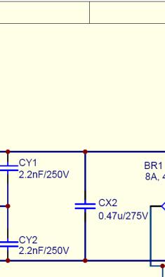
6 3 Technical Specifications Input voltage Input frequency Output voltage and current Output power Average efficiency Switching Frequency 85VAC~265VACC 47~63Hz 400VDC, 0.75A ~ 300W >95% at 115VACC 21kHz~100kHz 4 Line Input Circuit Description The AC line input side comprises the inputt fuse F1 as over-current protection. The choke L1, X2- capacitors CX1/CX2 and Y1-capacitor CY1/CY2 are used to suppress common mode noise as well as differential mode noise. RT1 is placed in series to limit inrush current during each power on. Power Stage Boost Type PFC Converter After the bridge rectifier BR1, there is a boost type PFC converter consisting c of f L3, Q1, D1 and C2. The third generationn CoolMOS IPP60R199P is used as the power switch Q1. BR1, Q1 and SiC Diode D1 share the same heat sink so that the system heat can be equably e spread. Output capacitor C2 provides energy buffering to reduce the output voltage ripple (100Hz) to the acceptable level l and meet the holdup time requirement. PWM Control of Boost Converter The ICE3PCS02G and ICE3PCS03G are 8-pins control IC for powerr factor correction converters. It is suitable for wide range line inputt applicationss from 85 to 265 VAC with overall efficiency above 93.5%. The IC supports converters in boost topology and it operates in continuous conduction mode (CCM) with average current control. The IC operates with a cascadedd control; thee inner current loop and the outer voltage loop. The inner current loop of the IC controls the sinusoidal profile for the average input current. It uses the dependency of the PWM duty cycle on the line input voltage to determine the corresponding input current. This means the averagee input current follows the input voltage as long ass the device operates in CCM. Under light load condition, depending on the choke inductance, the system may enter into discontinuous conduction mode (DCM) resulting in a higher harmonics but still meeting the Class D requirement of IEC The outer voltage loop controls the output bulk voltage, integrated digitally d within the IC. Depending on the load condition, internal PI compensation outputt is converted to an appropriate DC voltage which controls the amplitude of the average input current. The IC is equipped with various protection features to ensure safe operating condition for both the system and device. 6


7 5 Circuit Operation 5.1 Soft Startup During power up when the V OU UT is less than 95% of the rated level, internal voltage loop output increases from initial voltage under the soft-start control. This resultss in a controlled linear increase of the input current from 0A thus reducing the current stresss in the power components. Once V OUT has reached 95% of the rated level, the soft-start control is released to achieve good regulation and dynamic response. 5.2 Gate Switching Frequency The switching frequency of the PFC converter can be set with an external resistor R FREQ at pin FREQ with reference to pin SGND. The voltage at pin FREQ is typical 1V. The corresponding capacitor for the oscillator is integrated in the device and the R FREQ /frequency is givenn in Figure 2. The recommended operating frequency range is from 21 khz to 100 khz. As an example, a R FREQ of 68kΩ at pin FREQ will set a switching frequency f f SW W of 65 khz typically. Figure 2: Frequency setting The switching frequency can be synchronized to the external pulse signal after 6 external pulses delay once the voltage at the FREQ pin is higher than 2.5V. The synchronization means two points. Firstly, the PFC switching frequency is tracking the external pulse signal frequency. Secondly, the falling edge of the PFC signal is triggered byy the rising edge of the external pulsee signal. The external R8 combined with R9 and the external diode, D6 can ensure FREQQ pin voltagee to be kept between 1.0V (clamped internally) and 5V (maximum pin voltage) ). If the external pulse signal has disappeared longer than 108us ( typical) the switching frequency will be synchronized to internal clock set by the external resistor R8. 7
8 5.3 Protection Features Input brown-out protection (BOP) ICE3PCS03G provides a new BOP featuree whereby it senses directly the input voltage for f Input- Brown-Out conditionn via an external resistor/ /capacitor/diode network. This network provides a filtered value of V IN which turns the IC on when the voltage at pin 5 (BOP) iss more than 1.25V. The IC I enters into the fault mode when BOP goes beloww 1.0V. The hysteresis prevents thee system to oscillate between normal and fault mode. Note also that the peak of V IN needs to be at least 20% of the t rated V OUT in order to overcome open loop protection and power up system Open loop protection (OLP) The open loop protection is available for this IC to safe-guard the output. Whenever voltage at pin VSENSEE falls below 0.5V, or equivalently V O OUT falls below 20% of itss rated value, it indicates an open loop condition (i.e. VSENSE pin not connected). In this case, most of o the blockss within the IC will be shutdown. It is implemented using a comparator with a threshold of 0.5V First over-voltage protection (OVP1) Whenever V OUT exceeds the rated value by 8%, the first over-voltagee protection OVP1 is active. This is implemented by sensing the voltage at pinn VSENSE with respect to a reference voltage of 2.7V. A VSENSEE voltage higher than 2.7V will immediately block the gate signal. After bulk voltage falls below the rated value, gate drive resumes switchingg again Second over-voltage protection (OVP2) The second OVP (OVP2) is provided in case that the first one fails due to the aging or incorrect resistorss connected to the VSENSE pin. This is implemented by sensing the voltage at pin OVP with respect to a reference voltage of 2.5V. When voltage at OVP pin is higher than 2.5V, the IC will immediately turn offf the gate, thereby preventing damage to bus capacitor. c When the bulk voltage drops out of the hysteresis, which is below 2..3V the IC begin auto soft-start. In normal operation the trigger level of OVP22 should be designed higher than OVP1. However in the conditionn of mains transient overshoot the bulk voltage may be pulled up to the peak value of mains that is higher than the threshold of OVP1 andd OVP2. In this case the OVP1 and OVP2 are triggered in the same time the IC will shut down the gate drive until bulk voltage falls out of the two protection hysteresis, then resume the gate drive again. This function is available in ICE3PCS02G Peak current limit The IC provides a cycle by cycle peak current limitation (PCL). It is active when the voltage at pin ISENSEE reaches -0. 4V. This voltage is amplified by a factor of -2.5 and a connected to comparator with a reference voltage of 1.0V. A deglitcher withh 200ns after the comparator improves noise immunity to the activation of this protection. In other words, the current sense resistor should be designed lower than -0.4V PCL for normal operation IC supply under voltage lockout When V CC voltage is below the under voltagee lockout threshold V CCU UVLO, typical 11V, IC is off and the gate drive is internally pull low to t maintain the off state. The current consumption is down to t 1.4mA only. 8


9 6 Circuit Diagram Figure 3: Schematic of 300W PFC demo board 9


10 7 7.1 PCB Layout Top overlay view 7.2 Bottom layer view 10
11 8 Component List Designator BR1 C1 C2 C4 C4A C5 C7 C8 C9 C10 C11 CX1 CX2 CY1 CY2 (Connecter) SYNC (Connecter) VCCC (Connecter) L N (Connecter) VOUT Part Type 8A, 400V 0.1uF/630V 220uF/450V 1.5 uf/ /50V 1.5 uf/ /50V 4.7nF/50V 6.8nF/50V 0.1uF/50V 47uF/25V 10nF/50V 10pF/50V 0.47uF, X1, 275V 0.47uF, X1, 275V 2.2nF, Y2, 250V 2.2nF, Y2, 250V SIP3-MOLEX 2-way PCB connecter 2-way PCB connecter 2-way PCB connecter D1 IDH04S60C D2 1N5408 D4 1N4007 D5 1N4007 D6 1N4148 F1 5A HEATSINK_KM100 Heatsink ICE3PCS02G/ IC1 ICE3PCS02G J1 jumperr wire J2 jumperr wire L1 2*3.9mH L3 750uH Q1 IPP60R199CP R1 68/0.25W, 1% R2 0.05/3W, 1% R3 10k/0.25W, 1% R4 3.3/0.25W, 1% R5 1.5M/0.25W, 1% R5A 1.5M/0.25W, 1% R6 27k/0.25W, 1% R6A 62k/0.25W, 1% R8 68k/0.25W, 1% R9 130k/0.25W, 1% R10 3.9M/0.25W, 5% R10A 3.9M/0.25W, 5% Description Bridge Rectifier Electrolytic Cap Electrolytic Cap Connector (SYNC) Connector (V CC ) Connector (V IN ) Connector (V OUT ) Diode Diode Diode Diode Diode Fuse DSO-8 GATE signal CM Choke PFC Choke Power MOSFET Metal Film Resistor Manufacturer/ Partt No. Vishay / KBU8G Epcos / B32652A6104J Epcos / B32922C3474M Epcos / B32922C3474M Epcos / B81123C1222M000 Epcos / B81123C1222M000 Infineon Technologies Vishay / 1N5408 Vishay / 1N4007 Vishay /1N4007 Infineon Technologies Epcoss / B82725J2602N20 Infineon Technologies Vishayy / LVR03R0500FE70 11
12 R11 R12 R12A R13 R13A RT1 SCREW1 SCREW2 SCREW3 SCREW4 SCREW5 SCREW6 SW1 VAR1 130k/0.25W, 1% 2M/0.25W, 1% 2M/0.25W, 1% 24k/0.25W, 1% 560k/0.25W, 1% S237/55 Diameter:2mm Diameter:2mm Diameter:2mm Diameter:2mm Diameter:2mm Diameter:2mm 3 pin PCB P header S10K275 NTC Thermistor PCB stand PCB stand PCB stand PCB stand Heatsink Heatsink Varistor Epcos / B57237S509M Epcoss / B72210S271K101 9 Boost Choke Layout Core: PQ-core PQ3535 (TDK) Material: PC95 Inductance: L=750uH Windings 1 Start 1 End Wire 6 100x0.1mmm Litz Turns Layers 70 4 or 5 Method Tight Pin 1 Pin 2 Pin 3 Pin 4 Pin 5 Pin 6 TOP VIEW Removee Pin Pin 12 Pin 11 Pin 10 Pin 9 Pin 8 Pin 7 Pin 1 Pin 6 No Margin tape Winding 1: 70 turns//100x0.1mm Litz//tight Core Center Limb Length 20.8mm No Margin tape 12
13 Test report Load and Line Test Input 85V 115V 230V 265V V in (V) I in (I) V o out(v) I out t(i) P out (W) Efficiency PF
14 ICE3PCS02/03G Efficiency V 115V 230V 265V Efficiency(%) Output Power (W) Figure 4: PFC stage efficiency ICE3PCS02/03G PF PF V 115V 230V 265V Output Power (W) Figure 5: Power factor 14
15 10.2 Load and Line Test without NTC(5Ω) Input 85V 115V 230V 265V V in (V) I in (I) V o ut(v) I out t(i) P out ( W) Eff. PF
16 ICE3PCS02/03G Efficiency - No NTC Efficiency(%) V No NTC 115V No NTC 230V No NTC 265V No NTC Output Power (W) Figure 6: PFC stage efficiency without NTC (5Ω) 16
17 Harmonic test according to EN Class D requirement Test condition I: 85VAC input measurement class D measurement class D current (A) 0.6 current (A) harmonics (Vac=85V Po=300W Kp=1) harmonics (Vac=85V Po=60W Kp=1) Harmonics at 300W output Harmonics at 60W outputt Test condition II: 265VAC input measurement class D measurement class D current (A) 0.6 current (A) harmonics (Vac=265V Po=300W Kp=1, Boost Follower) harmonics (Vac=265V Po=60W Kp=1, Boost Follower) Harmonics at 300W output Harmonics at 60W outputt 17


18 11 Test Waveforms BOP triggered startup VCC triggered startup Figure 7: Startup test at 85VAC, 300W During startup the average current of PFC choke increases from zeroo to maximumm limited by PCL and PFC output voltage rises gradually with very slight overshoot. Pout from 0W to 300W Pout from 300W to 0W Figure 8: Load jump test at 85VAC The under shoot of output voltage is only 63VV when load jump from no n load to full load at 85Vac while the overshoot is within 33V vice versa. The choke current shows no distortion during load dynamic change. 18


![12 References: [1] ICE3PCS02G and ICE3PCS03G](/docs-images/82/86741263/images/19-8.jpg "datasheet, Infineon Technologies AG, 2010.")
![[2] Luo Junyang, Liu Jianwei and Jeoh Meng Kiat,](/docs-images/82/86741263/images/19-9.jpg "Design tips for CCM PFCC controller ICE2PCSxx,")


19 Enter brown-out and leave brown-out, Pout: : 300W Figure 9: Brownout and OLP test Open Loop protection n at 85V, Pout: 150W The gate drive is latched off once BOP pin voltage is lower than 1V and a initiates another soft-startup an inadequatee output voltage and initiates another soft-startup once Vsense voltagee is higher than 0.5V as shown in the right picture. once BOP voltage is higher than 1.25V as shown in the left picture. The gate drive can also be latched off oncee Vsense pin voltage is below b 0.5V indicating Auto Restart Mode Figure 10: OVP2 test When OVP2 happens the gate drive the willl shut down and enter auto startup when the voltage at OVP pin drop below 2.3V. 12 References: [1] ICE3PCS02G and ICE3PCS03G datasheet, Infineon Technologies AG, [2] Luo Junyang, Liu Jianwei and Jeoh Meng Kiat, Design tips for CCM PFCC controller ICE2PCSxx, Application note, Infineon Technologies s, [3] Lim Teik Eng, Li Dong and Liu Jian Wei, 300W PFC evaluation board with CCM PFC controllerr ICE3PCS01G, Application note, Infineon Technologies, [4] Luo Junyang, Liu Jianwei and Jeoh Meng Kiat, ICE1PCS01 based boostt type CCM PFC design guide control loop modeling, Application note, Infineon Technologies,
EVALPFC-300W-ICE3PCS02/03G
 Application Note, V1.0, January 2011 EVALPFC-300W-ICE3PCS02/03G 300W PFC Evaluation Board with CCM PFC controller ICE3PCS02/03G Power Management & Supply N e v e r s t o p t h i n k i n g. Edition 2010-12-31
Application Note, V1.1, October 2009 EVALPFC2-ICE2PCS W PFC Evaluation Board with CCM PFC controller ICE2PCS01. Power Management & Supply
 Application Note, V1.1, October 2009 EVALPFC2-ICE2PCS01 300W PFC Evaluation Board with CCM PFC controller ICE2PCS01 Power Management & Supply N e v e r s t o p t h i n k i n g. Edition 2009-10-13 Published
EVALPFC-300W-IPP60R190P6
 EVALPFC-300W-IPP60R190P6 3 0 0 W P F C E v a l u a t i o n B o a r d I P P 6 0 R 1 9 0 P 6 w i t h C C M P F C c o n t r o l l e r IFAT PMM APS SE SL Steiner Alois Stückler Franz Zechner Florian (IFAT
Application Note, V2.0, March 2006 EVALPFC2-ICE1PCS W PFC Evaluation Board with CCM PFC controller ICE1PCS01. Power Management & Supply
 Application Note, V2.0, March 2006 EVALPFC2-ICE1PCS01 300W PFC Evaluation Board with CCM PFC controller ICE1PCS01 Power Management & Supply N e v e r s t o p t h i n k i n g. Edition 2006-03-27 Published
160W PFC Evaluation Board with DCM PFC controller TDA and CoolMOS
 Application Note Version 1.0 160W PFC Evaluation Board with DCM PFC controller TDA4863-2 and CoolMOS SPP08N50C3 Power Management & Supply TDA4863-2 SPP08N50C3 Ver1.0, _doc_release> N e v e
Application Note, V1.0, Nov 2004 ICE3B2565. SMPS Evaluation Board with CoolSET TM ICE3B2565. Power Management & Supply
 Application Note, V1.0, Nov 2004 ICE3B2565 SMPS Evaluation Board with CoolSET TM ICE3B2565 F3 Power Management & Supply N e v e r s t o p t h i n k i n g. Edition 2005-01-13 Published by Infineon Technologies
AN-EVALSF3-ICE3B0565J
 Application Note, V1.0, Sep 2005 AN-EVALSF3-ICE3B0565J 12W 5.0V SMPS Evaluation Board with CoolSET TM F3 ICE3B0565J Power Management & Supply N e v e r s t o p t h i n k i n g. Edition 2005-09-26 Published
Power Management & Supply. Design Note. Version 2.3, August 2002 DN-EVALSF2-ICE2B765P-1. CoolSET 80W 24V Design Note for Adapter using ICE2B765P
 Version 2.3, August 2002 Design Note DN-EVALSF2-ICE2B765P-1 CoolSET 80W 24V Design Note for Adapter using ICE2B765P Author: Rainer Kling Published by Infineon Technologies AG http://www.infineon.com/coolset
Application Note. EVALQS-190W-ICE2QS02G 190W Evaluation Board Based on Quasi-resonant Flyback Converter for LCD TV SMPS. Power Management & Supply
 Application Note, V1.1, 2 February 2009 Application Note EVALQS-190W-ICE2QS02G 190W Evaluation Board Based on Quasi-resonant Flyback Converter for LCD TV SMPS Power Management & Supply N e v e r s t o
AN-EVALSF3-ICE3BS03LJG
 Application Note, V1.0, Nov 2007 AN-EVALSF3-ICE3BS03LJG 60W 16V SMPS Evaluation Board with F3 controller ICE3BS03LJG Power Management & Supply N e v e r s t o p t h i n k i n g. Edition 2007-11-14 Published
N e v e r s t o p t h i n k i n g.
 Application Note, V., December 0 N e v e r s t o p t h i n k i n g. Edition 0--4 Published by Infineon Technologies Asia Pacific, 68 Kallang Way, 495 Singapore, Singapore Infineon Technologies AP 004.
CCM-PFC ICE3PCS02G. Standalone Power Factor Correction (PFC) Controller in Continuous Conduction Mode (CCM)
 Controller in Continuous Conduction Mode (CCM)") Standalone Power Factor Correction (PFC) Controller in Continuous Conduction Mode (CCM) Product Highlights High efficiency over the whole load range Lowest count of external components Accurate and adjustable
Standalone Power Factor Correction (PFC) Controller in Continuous Conduction Mode (CCM) Product Highlights High efficiency over the whole load range Lowest count of external components Accurate and adjustable
RT8465. Constant Voltage High Power Factor PWM Boost Driver Controller for MR16 Application. Features. General Description.
 RT8465 Constant Voltage High Power Factor PWM Boost Driver Controller for MR16 Application General Description The RT8465 is a constant output voltage, active high power factor, PWM Boost driver controller.
12V-65W WIDE-RANGE INPUT MAINS ADAPTER USING THE L6566B
 APPLICATION NOTE 12V-65W WIDE-RANGE INPUT MAINS ADAPTER USING THE L6566B Introduction This note describes the characteristics and the features of a 65 W reference board, wide-range input mains, AC-DC adapter
CoolSET TM Selection Guide
 CoolSET - New Type Numbering System Z Z CoolSET TM F2 Second generation off-line SMPS current mode controller with integrated CoolMOS power transistor as well as enhanced Protection Features and Lowest
LD /15/2011. Green-Mode PWM Controller with Frequency Swapping and Integrated Protections. Features. General Description.
 12/15/2011 Green-Mode PWM Controller with Frequency Swapping and Integrated Protections Rev. 02a General Description The LD7536 is built-in with several functions, protection and EMI-improved solution
Application Note AN- EVAL-2QR2280G-20W. 20W5V Evaluation Board with Quasi- Resonant CoolSET ICE2QR2280G. Power Management & Supply
 Application Note, V1.1, 23 May 2011 Application Note AN- EVAL-2QR2280G-20W 20W5V Evaluation Board with Quasi- Resonant CoolSET ICE2QR2280G Power Management & Supply N e v e r s t o p t h i n k i n g. Published
Power Control ICs EVALLED-TDA4863G-40W. Application Note. Industrial & Multimarket
 Power Control ICs EVALLED-TDA4863G-40W Single Stage High Power Factor Flyback Converter for Offline LED Supply TDA4863G TLE4305G Application Note Revision.0, 00-04-0 Industrial & Multimarket Edition 00-04-0
Power Management & Supply. Application Note. Version 3.0, Oct AN-EVALSF2-ICE2B765P2-3. CoolSET 80W 24V Evaluation Board using ICE2B765P2
 Version 3.0, Oct. 2003 Application Note AN-EVALSF2-ICE2B765P2-3 CoolSET 80W 24V Evaluation Board using ICE2B765P2 Author: Rainer Kling Published by Infineon Technologies AG http://www.infineon.com/coolset
CCM-PFC ICE3PCS03G. Standalone Power Factor Correction (PFC) Controller in Continuous Conduction Mode (CCM)
 Controller in Continuous Conduction Mode (CCM)") Standalone Power Factor Correction (PFC) Controller in Continuous Conduction Mode (CCM) Product Highlights High efficiency over the whole load range Lowest count of external components Accurate and adjustable
Standalone Power Factor Correction (PFC) Controller in Continuous Conduction Mode (CCM) Product Highlights High efficiency over the whole load range Lowest count of external components Accurate and adjustable
Driving 2W LEDs with ILD4120
 Application Note AN270 Revision: 0.4 Date: LED Driver & AF Discretes Edition 2011-09-13 Published by Infineon Technologies AG 81726 Munich, Germany 2011 Infineon Technologies AG All Rights Reserved. LEGAL
Reference Design Report for a 21W (42V/0.5A) LED Driver Using SFL900
 LED Driver Using SFL900") Reference Design Report for a 21W (42V/0.5A) LED Driver Using SFL900 Specification Application 90-264VAC Input; 42V/0.5A output LED Driver Author Document Number System Engineering Department SFL900_LED
Reference Design Report for a 21W (42V/0.5A) LED Driver Using SFL900 Specification Application 90-264VAC Input; 42V/0.5A output LED Driver Author Document Number System Engineering Department SFL900_LED
DESCRIPTION FEATURES PROTECTION FEATURES APPLICATIONS. RS2320 High Accurate Non-Isolated Buck LED Driver
 High Accurate Non-Isolated Buck LED Driver DESCRIPTION RS2320 is especially designed for non-isolated LED driver. The building in perfect current compensation function ensures the accurate output current.
2 8W 1 6 V E v a l u a t i o n B o a r d w i t h Q u a s i - R e s o n a n t C o o l S E T I C E 2 Q R G
 Application Note, V1.1, 1 March 2013 Application Note AN- EVAL-2QR0665G-28W 2 8W 1 6 V E v a l u a t i o n B o a r d w i t h Q u a s i - R e s o n a n t C o o l S E T I C E 2 Q R 0 6 6 5 G Power Management
Application Note, V1.2, Aug 2010 AN-EVAL3BR0665JF. 100W 18V SMPS Evaluation Board with CoolSET F3R ICE3BR0665JF. Power Management & Supply
 Application Note, V1.2, Aug 2010 AN-EVAL3BR0665JF 100W 18V SMPS Evaluation Board with CoolSET F3R ICE3BR0665JF Power Management & Supply N e v e r s t o p t h i n k i n g. Edition 2010-08-11 Published
D e m o B o a r d U s e r s M a n u a l. Demoboard Rev.1.0, Standard Power
 IFX80471SKV D e m o B o a r d U s e r s M a n u a l Demoboard Rev.1.0, 2012-05-15 Standard Power 1 Abstract Note: The following information is given as a guideline for the implementation of the device
ILD2035. MR16 3 W Control Board with ILD2035. Application Note AN214. Industrial and Multimarket. Revision: 1.0 Date:
 ILD2035 MR16 3 W Control Board with ILD2035 Application Note AN214 Revision: 1.0 Date: Industrial and Multimarket Edition Published by Infineon Technologies AG 81726 Munich, Germany 2011 Infineon Technologies
High Accurate non-isolated Buck LED Driver
 High Accurate non-isolated Buck LED Driver Features High efficiency (More than 90%) High precision output current regulation (-3%~+3%) when universal AC input voltage (85VAC~265VAC) Lowest cost and very
MP2313 High Efficiency 1A, 24V, 2MHz Synchronous Step Down Converter
 The Future of Analog IC Technology MP2313 High Efficiency 1A, 24V, 2MHz Synchronous Step Down Converter DESCRIPTION The MP2313 is a high frequency synchronous rectified step-down switch mode converter
The Test Report of FAN7621 Evaluation Board
 Document Number E/B Number Application The Test Report of FAN7621 Evaluation Board FSEB-FAN7621-LCD-035 FAN7621 2009.02.06 ver1.1 LCD TV Power Supply Featured Products FAN7621 Date. APR. 02. 2009 Design
Application Note, Rev.1.0, November 2010 TLE8366. The Demoboard. Automotive Power
 Application Note, Rev.1.0, November 2010 TLE8366 Automotive Power Table of Contents 1 Abstract...3 2 Introduction...3 3 The Demo board...4 3.1 Quick start...4 3.2 The Schematic...5 3.3 Bill of Material...6
TFT-LCD DC/DC Converter with Integrated Backlight LED Driver
 TFT-LCD DC/DC Converter with Integrated Backlight LED Driver Description The is a step-up current mode PWM DC/DC converter (Ch-1) built in an internal 1.6A, 0.25Ω power N-channel MOSFET and integrated
AND8324/D. 300 W, Wide Mains, PFC Stage Driven by the NCP1654
 300 W, Wide Mains, PFC Stage Driven by the NCP1654 Prepared by: Patrick Wang ON Semiconductor Introduction The NCP1654 is a Power Factor Controller to efficiently drive Continuous Conduction Mode (CCM)
Application Note ANPS ICE2QS02G. Power Management & Supply. Converter Design Using Quasi-resonant PWM Controller ICE2QS02G
 Application Note, Version 1.0, 26 June 2008 Application Note ANPS0027 - ICE2QS02G Converter Design Using Quasi-resonant PWM Controller ICE2QS02G Power Management & Supply N e v e r s t o p t h i n k i
MP2314 High Efficiency 2A, 24V, 500kHz Synchronous Step Down Converter
 The Future of Analog IC Technology MP2314 High Efficiency 2A, 24V, 500kHz Synchronous Step Down Converter DESCRIPTION The MP2314 is a high frequency synchronous rectified step-down switch mode converter
DESCRIPTION FEATURES APPLICATIONS TYPICAL APPLICATION. 500KHz, 18V, 2A Synchronous Step-Down Converter
 DESCRIPTION The is a fully integrated, high-efficiency 2A synchronous rectified step-down converter. The operates at high efficiency over a wide output current load range. This device offers two operation
CR6842. Green-Power PWM Controller with Freq. Jittering. Features. Applications. General Description. Leading-edge blanking on Sense input
 Green-Power PWM Controller with Freq. Jittering Features Low Cost, Green-Power Burst-Mode PWM Very Low Start-up Current ( about 7.5µA) Low Operating Current ( about 3.0mA) Current Mode Operation Under
LD7750 2/23/2010. High Voltage Green-Mode PWM Controller with Over Temperature Protection. Features. Applications. Typical Application
 Rev. 00b General Description High Voltage Green-Mode PWM Controller with Over Temperature Protection Features LD7750 2/23/2010 The LD7750 integrates several functions of protections, and EMI-improved solution
4.5V to 32V Input High Current LED Driver IC For Buck or Buck-Boost Topology CN5816. Features: SHDN COMP OVP CSP CSN
 4.5V to 32V Input High Current LED Driver IC For Buck or Buck-Boost Topology CN5816 General Description: The CN5816 is a current mode fixed-frequency PWM controller for high current LED applications. The
ACE726C. 500KHz, 18V, 2A Synchronous Step-Down Converter. Description. Features. Application
 Description The is a fully integrated, high-efficiency 2A synchronous rectified step-down converter. The operates at high efficiency over a wide output current load range. This device offers two operation
LD7591 3/4/2010. Transition-Mode PFC Controller with Fault Condition Protection. Features. General Description. Applications
 3/4/2010 Transition-Mode PFC Controller with Fault Condition Protection REV. 00 General Description The LD7591 is a voltage mode PFC controller operating on transition mode, with several integrated functions
Digital Control IC for Interleaved PFCs
 Digital Control IC for Interleaved PFCs Rosario Attanasio Applications Manager STMicroelectronics Presentation Outline 2 PFC Basics Interleaved PFC Concept Analog Vs Digital Control The STNRGPF01 Digital
23V, 3A, 340KHz Synchronous Step-Down DC/DC Converter
 23V, 3A, 340KHz Synchronous Step-Down DC/DC Converter Description The is a synchronous step-down DC/DC converter that provides wide 4.5V to 23V input voltage range and 3A continuous load current capability.
30V, 3.1A Monolithic Step-Down Switching Regulator. C5 100nF/25V 5 FB COMP GND 4. Fig. 1 Schematic 60.00%
 30V, 3.1A Monolithic Step-Down Switching Regulator 1 Features 3.1A continuous output current capability 6.5V to 30V wide operating input range with input Over Voltage Protection Integrated 36V, 79mΩ high
CoolSET F3 Latch & Jitter Mode ICE3A1065LJ. 6 th Sept., Beijing. Infineon. Tim Hu. 7Apr06 Page 1. Page 1
 CoolSET F3 Latch & Jitter Mode ICE3A1065LJ Infineon 7Apr06 Page 1 Page 1 6 th Sept., 2006 - Beijing Infineon Integrated Power IC - CoolSET TM AC ~ V o DC IC T 2 CoolSET TM F3 Depl CoolMOS PWM IC 7Apr06
FL7732 Single-Stage PFC Primary-Side-Regulation Offline LED Driver
 FL7732 Single-Stage PFC Primary-Side-Regulation Offline LED Driver Features Cost-Effective Solution: No Input Bulk Capacitor or Feedback Circuitry Power Factor Correction Accurate Constant-Current (CC)
PCB layout guidelines for MOSFET gate driver
 AN_1801_PL52_1801_132230 PCB layout guidelines for MOSFET gate driver About this document Scope and purpose The PCB layout is essential to the optimal function of the MOSFET gate driver. It is also essential
Applications of 1EDNx550 single-channel lowside EiceDRIVER with truly differential inputs
 AN_1803_PL52_1804_112257 Applications of 1EDNx550 single-channel lowside EiceDRIVER with About this document Scope and purpose This application note shows the potential of the 1EDNx550 EiceDRIVER family
Infineon LLC IC solution & QR Coolset. Willion Chen ASIC & IC System Application Engineer
 Infineon LLC IC solution & QR Coolset Willion Chen ASIC & IC System Application Engineer Infineon LLC Solution for LED TV LLC stage ICE2HS01G Timer EnA OCP LOAD FREQ TD Delay Vref Vmc Vres ICE2HS01G PG-DSO-20
LD7536R 05/11/2010. Green-Mode PWM Controller with Frequency Swapping and Integrated Protections. General Description. Features.
 05/11/2010 Green-Mode PWM Controller with Frequency Swapping and Integrated Protections Rev. 00 General Description The LD7536R is built-in with several functions, protection and EMI-improved solution
FL7730 Single-Stage Primary-Side-Regulation PWM Controller for PFC and LED Dimmable Driving
 October 2012 FL7730 Single-Stage Primary-Side-Regulation PWM Controller for PFC and LED Dimmable Driving Features Compatible with Traditional TRIAC Control (No need to change existing lamp infrastructure:
ICE1PCS01 - Technical Description
 Application Note, V1.2, 29.10.2003 ICE1PCS01 - Technical Description AN-PFC-ICE1PCS01-1 Author: Wolfgang Frank http://www.infineon.com/pfc Power Management & Supply Never stop thinking. Revision History:
800 W PFC evaluation board
 800 W PFC evaluation board EVAL_800W_PFC_C7_V2 / SP001647120 / SA001647124 High power density 800 W 130 khz platinum server design with analog & digital control Garcia Rafael (IFAT PMM ACDC AE) Zechner
LD7577 1/15/2009. High Voltage Green-Mode PWM Controller with Brown-Out Protection. General Description. Features. Applications. Typical Application
 Rev. 01 General Description High Voltage Green-Mode PWM Controller with Brown-Out Protection The LD7577 integrates several functions of protections, and EMI-improved solution in SOP-8 package. It minimizes
Green-Mode PWM Controller with Integrated Protections
 Green-Mode PWM Controller with Integrated Protections Features Current mode control Very low startup current Under-voltage lockout (UVLO) Non-audible-noise green-mode control Programmable switching frequency
TLE8366. Data sheet. Automotive Power. 1.8A DC/DC Step-Down Voltage Regulator TLE8366EV50 TLE8366EV TLE8366EV33. Rev. 1.
 1.8A DC/DC Step-Down Voltage Regulator TLE8366EV50 TLE8366EV TLE8366EV33 Data sheet Rev. 1.0, 2009-05-18 Automotive Power 1.8A DC/DC Step-Down Voltage Regulator TLE8366 1 Overview 1.8A step down voltage
HF A 27V Synchronous Buck Converter General Description. Features. Applications. Package: TBD
 General Description The is a monolithic synchronous buck regulator. The device integrates 80 mω MOSFETS that provide 4A continuous load current over a wide operating input voltage of 4.5V to 27V. Current
TS mA / 1.5MHz Synchronous Buck Converter
 SOT-25 Pin Definition: 1. EN 2. Ground 3. Switching Output 4. Input 5. Feedback General Description The TS3406 is a high efficiency monolithic synchronous buck regulator using a 1.5MHz constant frequency,
LD7552B 1/2/2008. Green-Mode PWM Controller with Integrated Protections. General Description. Features. Applications. Typical Application. Rev.
 Rev. 01a LD7552B 1/2/2008 Green-Mode PWM Controller with Integrated Protections General Description The LD7552B are low cost, low startup current, current mode PWM controllers with green-mode power- saving
N386X APPLICATION INFORMATION
 N386X APPLICATION INFORMATION Prepared by : Alex Leng The N386X is a low cost high integrated PWM primary switcher, it combines a current mode controller with a high voltage power MOSFET and integrates
LD7536E 5/28/2012. Green-Mode PWM Controller with Frequency Swapping and Integrated Protections. General Description. Features.
 5/28/2012 Green-Mode PWM Controller with Frequency Swapping and Integrated Protections Rev. 00 General Description The is built-in with several functions, protection and EMI-improved solution in a tiny
TS19702 High Power Factor Corrector LED Driver
 SOT-26 Pin Definition: 1. VCC 2. Ground 3. Output 4. Dimming 5. Compensation 6. Current Sense Description The TS19702 is a highly-integrated, low startup current, average current mode, one cycle control
Boundary Mode Offline LED Driver Using MP4000. Application Note
 The Future of Analog IC Technology AN046 Boundary Mode Offline LED Driver Using MP4000 Boundary Mode Offline LED Driver Using MP4000 Application Note Prepared by Zheng Luo March 25, 2011 AN046 Rev. 1.0
Fixed with 65kHz (AP3125A/V/R/L/B/ST) 100kHz (AP3125HA/HB) VFB Resistor 10kΩ 15kΩ. Standby Performance Better Best
 100kHz (AP3125HA/HB) VFB Resistor 10kΩ 15kΩ. Standby Performance Better Best") APPLICATION NOTE 1120 GREEN MODE PWM CONTROLLER Introduction The AP3125 series is a low start-up current, current mode PWM controller with green-mode power-saving operation. AP3125 series PWM switching
APPLICATION NOTE 1120 GREEN MODE PWM CONTROLLER Introduction The AP3125 series is a low start-up current, current mode PWM controller with green-mode power-saving operation. AP3125 series PWM switching
LSP5502 2A Synchronous Step Down DC/DC Converter
 FEATURES 2A Output Current Wide 4.5V to 27V Operating Input Range Integrated 20mΩ Power MOSFET Switches Output Adjustable from 0.925V to 24V Up to 96% Efficiency Programmable Soft-Start Stable with Low
NCP1631EVB/D. NCP1631 Evaluation Board Manual. Performance of a 300 W, Wide Mains Interleaved PFC Driven by the NCP1631 EVALUATION BOARD MANUAL
 P1631EVB/D P1631 Evaluation Board Manual Performance of a 300 W, Wide Mains Interleaved PFC Driven by the P1631 Prepared by: Stephanie Conseil ON Semiconductor EVALUATION BOARD MANUAL The P1631 is a dual
Control integrated Power System (CIPOS )
") Application Note, V1.0, Oct. 2008 Control integrated Power System (CIPOS ) Reference Board for CIPOS TM IKCSxxF60B(2)x AN-CIPOS-Reference Board-2 Authors: Junbae Lee http://www.infineon.com/cipos Power
Application Note, V1.0, Oct. 2008 Control integrated Power System (CIPOS ) Reference Board for CIPOS TM IKCSxxF60B(2)x AN-CIPOS-Reference Board-2 Authors: Junbae Lee http://www.infineon.com/cipos Power
Designing Offline HB LED Current Sources with Primary Side Control Using E-series Fairchild Power Switch (FPS)
") Designing Offline HB LED Current Sources with Primary Side Control Using E-series Fairchild Power Switch (FPS) Carl Walding Global Power Resource Center, Hoffman Estates, IL www.fairchildsemi.com Overview
Designing Offline HB LED Current Sources with Primary Side Control Using E-series Fairchild Power Switch (FPS) Carl Walding Global Power Resource Center, Hoffman Estates, IL www.fairchildsemi.com Overview
Application Note, V1.0, Sep 2011 AN-EVAL3BR1465JF. 60W 18V SMPS Evaluation Board with CoolSET F3R ICE3BR1465JF. Power Management & Supply
 Application Note, V1.0, Sep 2011 AN-EVAL3BR1465JF 60W 18V SMPS Evaluation Board with CoolSET F3R ICE3BR1465JF Power Management & Supply N e v e r s t o p t h i n k i n g. Published by Infineon Technologies
ISL6721EVAL Current Mode Active Clamp Forward with SR for Middle Power Level Applications
 ISL6721EVAL Current Mode Active Clamp Forward with SR for Middle Power Level Applications Introduction: The ISL6721EVAL board is a 48V input to 3.3V output DC/DC converter which can output current up to
Evaluates: MAX V Output-Voltage Application. MAX17632C Evaluation Kit. General Description. Quick Start. Features. Recommended Equipment
 General Description The MAX17632C 5V output evaluation kit (EV kit) provides a proven design to evaluate the MAX17632C highefficiency, synchronous step-down DC-DC converter. The EV kit provides 5V/2A at
FEBFSL336LRN_CS04U07A Evaluation Board. Fairchild Multi-Output Buck Converter. Featured Fairchild Product: FSL336LRN
 User Guide for FEBFSL336LRN_CS04U07A Evaluation Board Fairchild Multi-Output Buck Converter Featured Fairchild Product: FSL336LRN Direct questions or comments about this evaluation board to: Worldwide
Green-Mode PWM Controller with Integrated Protections
 Green-Mode PWM Controller with Integrated Protections Features High-voltage (500) startup circuit Current mode PWM ery low startup current (
Dimmable LED Driver with iw3614. (Input 230Vac Output 24V350mA)
") Dimmable LED Driver with iw3614 (Input 230Vac Output 24V350mA) 1. Design Purpose and Feature Isolated ac-dc offline, Input 230Vac, Output 7 LEDs 350mA Intelligent wall dimmer detections - Leading-edge
Dimmable LED Driver with iw3614 (Input 230Vac Output 24V350mA) 1. Design Purpose and Feature Isolated ac-dc offline, Input 230Vac, Output 7 LEDs 350mA Intelligent wall dimmer detections - Leading-edge
AT V,3A Synchronous Buck Converter
 FEATURES DESCRIPTION Wide 8V to 40V Operating Input Range Integrated 140mΩ Power MOSFET Switches Output Adjustable from 1V to 25V Up to 93% Efficiency Internal Soft-Start Stable with Low ESR Ceramic Output
Application Note, V1.1, Apr CoolMOS TM. AN-CoolMOS-08 SMPS Topologies Overview. Power Management & Supply. Never stop thinking.
 Application Note, V1.1, Apr. 2002 CoolMOS TM AN-CoolMOS-08 Power Management & Supply Never stop thinking. Revision History: 2002-04 V1.1 Previous Version: V1.0 Page Subjects (major changes since last revision)
Fairchild Reference Design
 Fairchild Reference Design www.fairchildsemi.com This reference design supports inclusion of the FSL306LRN. It should be used in conjunction with the FSL306LRN datasheet as well as Fairchild s application
5V/550mA Battery Charger Solution Using AP3703
 System Engineering Department BCD Semiconductor Manufacturing Limited 01/19/2009 Summary of Report Specifications 85~264Vac, 5V/550mA Applications Key features Cellphone charger or adapter Primary Side
SR A, 30V, 420KHz Step-Down Converter DESCRIPTION FEATURES APPLICATIONS TYPICAL APPLICATION
 SR2026 5A, 30V, 420KHz Step-Down Converter DESCRIPTION The SR2026 is a monolithic step-down switch mode converter with a built in internal power MOSFET. It achieves 5A continuous output current over a
ICB2FL02G. Smart Ballast Control IC for Fluorescent Lamp Ballasts. Power Management & Drives. Preliminary Datasheet V1.2
 Preliminary Datasheet ICB2FL02G Smart Ballast Control IC for Fluorescent Lamp Ballasts Published by Infineon Technologies AG http://www.infineon.com Power Management & Drives Never stop thinking ICB2FL02G
Green-Mode PWM Controller with Integrated Protections
 Green-Mode PWM Controller with Integrated Protections Features Current mode PWM Very low startup current Under-voltage lockout (UVLO) Non-audible-noise green-mode control Programmable switching frequency
POWER MANAGEMENT PRODUCTS. Application Note. Simple PWM Boost Converter with I/O Disconnect Solves Malfunctions Caused when V OUT <V IN
 POWER MANAGEMENT PRODUCTS Application Note Simple PWM Boost Converter with I/O Disconnect Solves Malfunctions Caused when V OUT
Green-Mode PWM Controller with Integrated Protections
 Green-Mode PWM Controller with Integrated Protections Features High-voltage (500) startup circuit Current mode PWM ery low startup current (
FR V, 3.5A, 340KHz Synchronous Step-Down DC/DC Converter. Features. Description. Applications. Pin Assignments. Ordering Information
 23V, 3.5A, 340KHz Synchronous Step-Down DC/DC Converter Description The is a synchronous step-down DC/DC converter that provides wide 4.5V to 23V input voltage range and 3.5A continuous load current capability.
LD7523 6/16/2009. Smart Green-Mode PWM Controller with Multiple Protections. General Description. Features. Applications. Typical Application REV: 00
 6/16/2009 Smart Green-Mode PWM Controller with Multiple Protections REV: 00 General Description The LD7523 is a low startup current, current mode PWM controller with green-mode power-saving operation.
MP2324 High Efficiency 2A, 24V, 500kHz Synchronous Step-Down Converter
 MP2324 High Efficiency 2A, 24V, 500kHz Synchronous Step-Down Converter DESCRIPTION The MP2324 is a high frequency synchronous rectified step-down switch mode converter with built in internal power MOSFETs.
Features. Applications. 1.2MHz Boost Converter with OVP in Thin SOT-23-6
 1.2MHz PWM Boost Converter with OVP General Description The is a 1.2MHz pulse width modulated (PWM) step-up switching regulator that is optimized for low power, high output voltage applications. With a
LM5034 High Voltage Dual Interleaved Current Mode Controller with Active Clamp
 High Voltage Dual Interleaved Current Mode Controller with Active Clamp General Description The dual current mode PWM controller contains all the features needed to control either two independent forward/active
DESCRIPTION FEATURES APPLICATIONS TYPICAL APPLICATION
 MP5016 2.7V 22V, 1A 5A Current Limit Switch with Over Voltage Clamp and Reverse Block The Future of Analog IC Technology DESCRIPTION The MP5016 is a protection device designed to protect circuitry on the
ANP012. Contents. Application Note AP2004 Buck Controller
 Contents 1. AP004 Specifications 1.1 Features 1. General Description 1. Pin Assignments 1.4 Pin Descriptions 1.5 Block Diagram 1.6 Absolute Maximum Ratings. Hardware.1 Introduction. Typical Application.
Features. General Description. Component List
 MAX68 Evaluation Kit Evaluates: MAX68 General Description The MAX68 evaluation kit (EV kit) demonstrates the MAX68 high-brightness LED (HB LED) driver, integrating a step-up DC-DC preregulator followed
Green-Mode PWM Controller with Hiccup Protection
 Green-Mode PWM Controller with Hiccup Protection Features Current Mode Control Standby Power below 100mW Under-Voltage Lockout (UVLO) Non-Audible-Noise Green-Mode Control 65KHz Switching Frequency Internal
Constant Current Switching Regulator for White LED
 Constant Current Switching Regulator for White LED FP7201 General Description The FP7201 is a Boost DC-DC converter specifically designed to drive white LEDs with constant current. The device can support
AN2000 Application note
 Application note VIPower: VIPer53A dual output reference board 90 to 264 VAC input, 24W output Introduction This is an off-line wide range VIPer53 dual output reference board that is set up for secondary
Step down - LED controller IC for external power stages ILD4001
 Target Datasheet, Rev. 1.0, July 2009 Step down - LED controller IC for external power stages ILD4001 Small Signal Discretes Edition 2009-07-06 Published by Infineon Technologies AG, 81726 München, Germany
MP2482 5A, 30V, 420kHz Step-Down Converter
 The Future of Analog IC Technology DESCRIPTION The MP2482 is a monolithic step-down switch mode converter with a built in internal power MOSFET. It achieves 5A continuous output current over a wide input
A7221A DC-DC CONVERTER/BUCK (STEP-DOWN) 600KHz, 16V, 2A SYNCHRONOUS STEP-DOWN CONVERTER
 600KHz, 16V, 2A SYNCHRONOUS STEP-DOWN CONVERTER") DESCRIPTION The is a fully integrated, high efficiency 2A synchronous rectified step-down converter. The operates at high efficiency over a wide output current load range. This device offers two operation
DESCRIPTION The is a fully integrated, high efficiency 2A synchronous rectified step-down converter. The operates at high efficiency over a wide output current load range. This device offers two operation
Low-Noise 4.5A Step-Up Current Mode PWM Converter
 Low-Noise 4.5A Step-Up Current Mode PWM Converter FP6298 General Description The FP6298 is a current mode boost DC-DC converter. It is PWM circuitry with built-in 0.08Ω power MOSFET make this regulator
1200mA step down - LED controller IC ILD4120
 Target Datasheet, Rev. 1.0, July 2009 ILD4120 Small Signal Discretes Edition 2009-07-06 Published by Infineon Technologies AG, 81726 München, Germany Infineon Technologies AG 2009. All Rights Reserved.
MP1495 High Efficiency 3A, 16V, 500kHz Synchronous Step Down Converter
 The Future of Analog IC Technology DESCRIPTION The MP1495 is a high-frequency, synchronous, rectified, step-down, switch-mode converter with built-in power MOSFETs. It offers a very compact solution to