Digital Control IC for Interleaved PFCs
|
|
|
- Emerald Hall
- 6 years ago
- Views:
Transcription

1 Digital Control IC for Interleaved PFCs Rosario Attanasio Applications Manager STMicroelectronics
2 Presentation Outline 2 PFC Basics Interleaved PFC Concept Analog Vs Digital Control The STNRGPF01 Digital Controller Main Functions Edesign suite GUI Application Example: 3kW Three channel Interleaved PFC Performance Evaluation Conclusions
3 Power Factor Correction 5 A PFC is the input stage of an AC/DC converter connected to the AC mains to address the need to limit energy consumption A PFC pre-regulator placed between the bridge and the bulk capacitor draws a quasi-sinusoidal current from the mains, in-phase with the line voltage Harmonic current emission is regulated by IEC Lighting requirements > 25W, SMPS & chargers > 75W Maximize the energy delivery to load means to reduce the Total Harmonic Distortion (THD) and therefore maximize the Power Factor
4 Introduction to PFC 4 Kd= Distortion Factor Kϴ= Displacement Factor


5 Passive vs Active PFC 5 EMI Filter Rectifier PFC Main Converter Load SMPS Structure PFC stage can be Passive or Active. Passive: bulky capacitors and inductors Active: high frequency topologies
6 Passive PFC Topologies 6 AC side inductor PR Bandstop filter DC side inductor Harmonic Trap filter SR Bandpass filter LCD Rectifier
7 Active PFC Topologies 7 Main topologies for PFC stage: Boost (most used because it s stepping-up the voltage) Buck Flyback Cuk Sepic Operation modes: Continuous Conduction Mode (CCM) > 350W Transition Mode (TM) <350W Discontinuous Conduction Mode (DCM)
8 PFC Control Technique 8 Type Strengths Weakness Average current control Low distortion on input current Two control loops Peak Current control Fast current correction High distortion on input current Hysteresis Current control Fast current correction Low distortion on input current Need two comparators

9 PFC Interleaved Concept 9 L1 I1 PFC controller M1 Phase1 + Ic DC/DC or DC/AC Load LN In Mn Phase n

10 Single Channel Example: 3kW ipfc Switching frequency 100kHz 10 Interleaved 3 Channels Core: EE70 L= 150µH Size: h=70mm, W=66mm, D=31mm Volume=8.72 in 3 Core: PQ3230 L= 120µH Size: h=30mm, W=32mm, D=27mm Volume=1.58 in 3 Total Volume=4.74 in 3 45% Less!
11 Output Capacitor Ripple Current Reduction 11 RMS Current Reduction Single Channel 1 I cccccccc NNNNNNNNNNNNNNNNNNNN 0.5 Double Channel Triple Channel %D 1 Capacitors with higher ESR can be used Lower cost


12 Digital vs Analog PFC Control 12 Full digital control of PFC is already state of the art. More PFC topologies can be implemented More sophisticated control algorithms Availability of ICs for PFCs from many manufacturers Cycle by cycle control loop High bandwidth Low Cost Digital Control Analog Control

13 The STNRGPF01: Overview 13 TSSOP38 Package Mixed Signal Control Configurable By GUI

14 Semi-digital control Analog current controller The STNRGPF01: Overview 14 Voltage controller, feed-forward compensation, multiplier, PWM clock generator and nontime critical protection functions are implemented digitally. Interleaved boost PFC Up to 3 interleaved channels CCM, fixed frequency Average current control, cycle-by-cycle Inrush current control Burst mode support OCP, OVP and thermal protection Soft start-up Flexible phase-shedding strategy

15 STRNGPF01: Application Block Diagram 15
16 STNRGPF01: Voltage Loop 16 Output Voltage Sensing Internal control block scheme Input Voltage Sensing Output Current Sensing ZVD Sensing


17 STNRGPF01: Current Loop 17 Analog Current OP-Amp PI Internal control block scheme Itot_fb Itot_ref


")
18 STNRGPF01: Driving and Interleaving 18 Interleaving operation (internal) Internal control block scheme


19 STNRGPF01 GUI: edesign Suite Tool 19 BoM + SCHEMATIC Binary file generation Build edesignsuite smart configurator for STNRGPF01
 Input Voltage feed forward Load feed forward Working frequency = 111kHz per channel Thermal")
20 3kW Three Channels Interleaved PFC 20 The device performance have been evaluated developing a 3kW Three channels PFC. Pout = Vin = 230Vac; Vin = 110Vac Vout = 400V PF > 20% load THD < 20% load CCM with analog current control loop (cycle by cycle regulation) Input Voltage feed forward Load feed forward Working frequency = 111kHz per channel Thermal protection set at 120 C Current protection set at 33A Direct fan driving Current reference realized by internal map (200 pt) High Power Density 52W/in 3! Key Products L=24,5 cm; W=11 cm; H=3,5 cm (including heatsink area) STNRGPF01 (Digital controller for PFC) PM8834D (Double Channel low side driver) ALTAIR (Off-line primary-sens. switch. reg.) STW40N60M2 (MDmesh II Plus low Qg ) STPSC1206 Schottky silicon carbide diode TSV911 (High speed OP) LMV358 (Standard OP) M74HC132 (Quad NAND Gate)

21 Experimental Results: Steady State 21 Inductors current Duty cycle PWM master

22 Experimental Results: Load Feed Forward 22 Load step : 0W - 2kW DC Bus voltage Input current The load feed forward when load step is applied reduces the over and under voltage of the output dc bus voltage!

23 Experimental Results: Load Feed Forward 23 Load step sequence: 0.4kW - 2kW - 0.4kW DC Bus voltage Input current The load feed forward when load step is applied reduces the over and under voltage of the output dc bus voltage!

24 Experimental Results: Load Feed Forward 24 Load step sequence: 0W - 2kW - 0W DC Bus voltage Input current The PFC interrupts the Burst Mode to meet the load requirement and when load is disconnected it returns in Burst Mode.
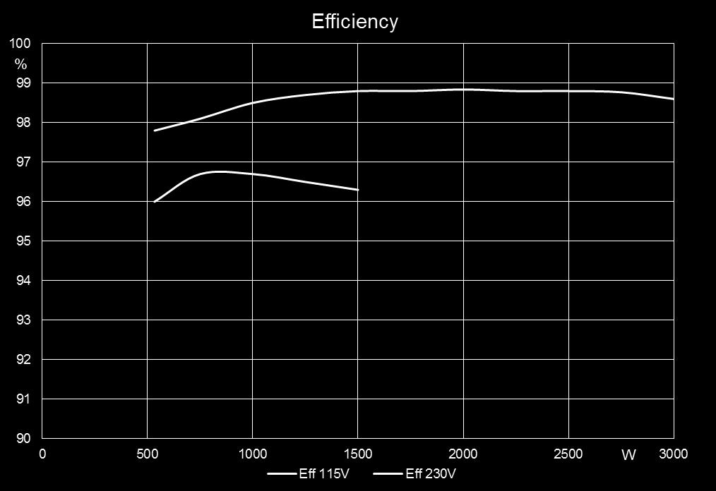
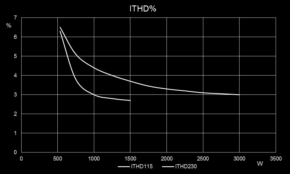
25 Experimental Results Efficiency and ITHD% 25
26 Conclusions 26 Interleaved PFC benefits include: the use of smaller components, better thermal performance, low current ripple The STNRGPF01 is a controller for CCM interleaved PFCs It supports up to three independent channels Cycle by Cycle current control allows fast dynamic response The STNRGPF01 can be easily and quickly configured using the edesign Suite GUI resulting in reduced development time, lower development cost and faster time-to-market
27 Thank You! 27
Demonstration. Agenda
 Demonstration Edward Lee 2009 Microchip Technology, Inc. 1 Agenda 1. Buck/Boost Board with Explorer 16 2. AC/DC Reference Design 3. Pure Sinewave Inverter Reference Design 4. Interleaved PFC Reference
Digital Controller Eases Design Of Interleaved PFC For Multi-kilowatt Converters
 ISSUE: June 2017 Digital Controller Eases Design Of Interleaved PFC For Multi-kilowatt Converters by Rosario Attanasio, Giuseppe Di Caro, Sebastiano Messina, and Marco Torrisi, STMicroelectronics, Schaumburg,
ST Power Factor Controllers. Luca Salati
 ST Power Factor Controllers Luca Salati PFC controller: what a PFC is? 2 Power factor (PF) it's a measure of the efficiency of a power distribution system A system with low PF for a given amount of power
GaN in Practical Applications
 in Practical Applications 1 CCM Totem Pole PFC 2 PFC: applications and topology Typical AC/DC PSU 85-265 V AC 400V DC for industrial, medical, PFC LLC 12, 24, 48V DC telecomm and server applications. PFC
Application - Power Factor Correction (PFC) with XMC TM. XMC microcontrollers July 2016
 with XMC TM. XMC microcontrollers July 2016") Application - Power Factor Correction (PFC) with XMC TM XMC microcontrollers July 2016 Agenda 1 Key features 2 Specification 3 System block diagram 4 Software overview 5 Highlight MCU features 6 CCM PFC
Application - Power Factor Correction (PFC) with XMC TM XMC microcontrollers July 2016 Agenda 1 Key features 2 Specification 3 System block diagram 4 Software overview 5 Highlight MCU features 6 CCM PFC
Welcome. High Efficiency SMPS with Digital Loop Control
 Welcome High Efficiency SMPS with Digital Loop Control Presenter: Walter Mosa Company: MagneTek IBM Power and Cooling Technology Symposium September 20-21st FE 1U 800-12 High Density AC/DC Front-End Design
Level-2 On-board 3.3kW EV Battery Charging System
 Level-2 On-board 3.3kW EV Battery Charging System Is your battery charger design performing at optimal efficiency? Datsen Davies Tharakan SYNOPSYS Inc. Contents Introduction... 2 EV Battery Charger Design...
IBM Technology Symposium
 IBM Technology Symposium Impact of Input Voltage on Server PSU- Efficiency, Power Density and Cost Design. Build. Ship. Service. Sriram Chandrasekaran November 13, 2012 Presentation Outline Redundant Server
CHAPTER 3. SINGLE-STAGE PFC TOPOLOGY GENERALIZATION AND VARIATIONS
 CHAPTER 3. SINGLE-STAGE PFC TOPOLOG GENERALIATION AND VARIATIONS 3.1. INTRODUCTION The original DCM S 2 PFC topology offers a simple integration of the DCM boost rectifier and the PWM DC/DC converter.
Bridgeless Cuk Power Factor Corrector with Regulated Output Voltage
 Bridgeless Cuk Power Factor Corrector with Regulated Output Voltage Ajeesh P R 1, Prof. Dinto Mathew 2, Prof. Sera Mathew 3 1 PG Scholar, 2,3 Professors, Department of Electrical and Electronics Engineering,
DSP-BASED CURRENT SHARING OF AVERAGE CURRENT CONTROLLED TWO-CELL INTERLEAVED BOOST POWER FACTOR CORRECTION CONVERTER
 DSP-BASED CURRENT SHARING OF AVERAGE CURRENT CONTROLLED TWO-CELL INTERLEAVED BOOST POWER FACTOR CORRECTION CONVERTER P.R.Hujband 1, Dr. B.E.Kushare 2 1 Department of Electrical Engineering, K.K.W.I.E.E.R,
The First Step to Success Selecting the Optimal Topology Brian King
 The First Step to Success Selecting the Optimal Topology Brian King 1 What will I get out of this session? Purpose: Inside the Box: General Characteristics of Common Topologies Outside the Box: Unique
Chapter 10 Switching DC Power Supplies
 Chapter 10 Switching One of the most important applications of power electronics 10-1 Linear Power Supplies Very poor efficiency and large weight and size 10-2 Switching DC Power Supply: Block Diagram
800 W PFC evaluation board
 800 W PFC evaluation board EVAL_800W_PFC_C7_V2 / SP001647120 / SA001647124 High power density 800 W 130 khz platinum server design with analog & digital control Garcia Rafael (IFAT PMM ACDC AE) Zechner
Fundamentals of Power Electronics
 Fundamentals of Power Electronics SECOND EDITION Robert W. Erickson Dragan Maksimovic University of Colorado Boulder, Colorado Preface 1 Introduction 1 1.1 Introduction to Power Processing 1 1.2 Several
Cree PV Inverter Tops 1kW/kg with All-SiC Design
 Cree PV Inverter Tops 1kW/kg with All-SiC Design Alejandro Esquivel September, 2014 Power Forum 2014 (Bologna) presentation sponsored by: Presentation Outline 1. Meeting an Industry Need a) 1kW/Kg b) No
Implementation Of Bl-Luo Converter Using FPGA
 Implementation Of Bl-Luo Converter Using FPGA Archa.V. S PG Scholar, Dept of EEE, Mar Baselios College of Engineering and Technology, Trivandrum Asst. Prof. C. Sojy Rajan Assistant Professor, Dept of EEE,
AC-DC SMPS: Up to 15W Application Solutions
 AC-DC SMPS: Up to 15W Application Solutions Yehui Han Applications Engineer April 2017 Agenda 2 Introduction Flyback Topology Optimization Buck Topology Optimization Layout and EMI Optimization edesignsuite
A Single Phase Single Stage AC/DC Converter with High Input Power Factor and Tight Output Voltage Regulation
 638 Progress In Electromagnetics Research Symposium 2006, Cambridge, USA, March 26-29 A Single Phase Single Stage AC/DC Converter with High Input Power Factor and Tight Output Voltage Regulation A. K.
Designing High-Efficiency ATX Solutions. Practical Design Considerations & Results from a 255 W Reference Design
 Designing High-Efficiency ATX Solutions Practical Design Considerations & Results from a 255 W Reference Design Agenda Regulation and Market Requirements Target Specification for the Reference Design Architectural
POWER FACTOR CORRECTION USING AN IMPROVED SINGLE-STAGE SINGLE- SWITCH (S 4 ) TECHNIQUE
 TECHNIQUE") International Journal of Power Systems and Microelectronics (IJMPS) Vol. 1, Issue 1, Jun 2016, 45-52 TJPRC Pvt. Ltd POWER FACTOR CORRECTION USING AN IMPROVED SINGLE-STAGE SINGLE- SWITCH (S 4 ) TECHNIQUE
International Journal of Power Systems and Microelectronics (IJMPS) Vol. 1, Issue 1, Jun 2016, 45-52 TJPRC Pvt. Ltd POWER FACTOR CORRECTION USING AN IMPROVED SINGLE-STAGE SINGLE- SWITCH (S 4 ) TECHNIQUE
Using the Latest Wolfspeed C3M TM SiC MOSFETs to Simplify Design for Level 3 DC Fast Chargers
 Using the Latest Wolfspeed C3M TM SiC MOSFETs to Simplify Design for Level 3 DC Fast Chargers Abstract This paper will examine the DC fast charger market and the products currently used in that market.
Design and Simulation of New Efficient Bridgeless AC- DC CUK Rectifier for PFC Application
 Design and Simulation of New Efficient Bridgeless AC- DC CUK Rectifier for PFC Application Thomas Mathew.T PG Student, St. Joseph s College of Engineering, C.Naresh, M.E.(P.hd) Associate Professor, St.
PAM2421 EVB User Guide
 EV Board User Guide AE Department 1. Revision Information PAM2421 Date Revision Description Comment 2011/09 V1.0 Initial Release 2. PAM2804 General Description The PAM2421 devices are high-performance,
Designing High density Power Solutions with GaN Created by: Masoud Beheshti Presented by: Xaver Arbinger
 Designing High density Power Solutions with GaN Created by: Masoud Beheshti Presented by: Xaver Arbinger Topics Why GaN? Integration for Higher System Performance Application Examples Taking GaN beyond
Single Phase Bridgeless SEPIC Converter with High Power Factor
 International Journal of Emerging Engineering Research and Technology Volume 2, Issue 6, September 2014, PP 117-126 ISSN 2349-4395 (Print) & ISSN 2349-4409 (Online) Single Phase Bridgeless SEPIC Converter
Power Factor Correction in Digital World. Abstract. 1 Introduction. 3 Advantages of Digital PFC over traditional Analog PFC.
 Power Factor Correction in Digital World By Nitin Agarwal, STMicroelectronics Pvt. Ltd., India Abstract There are various reasons why power factor correction circuit is used in various power supplies in
Reference Design. TDTTP3300-RD 3.3kW Bridgeless Totem-pole PFC. Test Report
 Reference Design TDTTP3300-RD 3.3kW Bridgeless Totem-pole PFC Table of Contents 1 Introduction... 4 1.1 Design resources... 4 2 Power supply specifications... 5 3 3-D board image... 6 4 Performance data...
Low-Noise 4.5A Step-Up Current Mode PWM Converter
 Low-Noise 4.5A Step-Up Current Mode PWM Converter FP6298 General Description The FP6298 is a current mode boost DC-DC converter. It is PWM circuitry with built-in 0.08Ω power MOSFET make this regulator
ST s Solutions for LED General Illumination
 ST s Solutions for LED General Illumination ST LED Lighting Solutions Low Power (75w) Design Software HVLED8XX Controller + MOSFET Embedded with 800V MOSFET
A NEW SINGLE STAGE THREE LEVEL ISOLATED PFC CONVERTER FOR LOW POWER APPLICATIONS
 A NEW SINGLE STAGE THREE LEVEL ISOLATED PFC CONVERTER FOR LOW POWER APPLICATIONS S.R.Venupriya 1, Nithyananthan.K 2, Ranjidharan.G 3, Santhosh.M 4,Sathiyadevan.A 5 1 Assistant professor, 2,3,4,5 Students
A Control Scheme for an AC-DC Single-Stage Buck-Boost PFC Converter with Improved Output Ripple Reduction
 Western University Scholarship@Western Electronic Thesis and Dissertation Repository August 2012 A Control Scheme for an AC-DC Single-Stage Buck-Boost PFC Converter with Improved Output Ripple Reduction
Coupled Inductor Based Single Phase CUK Rectifier Module for Active Power Factor Correction
 Bonfring International Journal of Power Systems and Integrated Circuits, Vol. 3, No. 3, September 2013 22 Coupled Inductor Based Single Phase CUK Rectifier Module for Active Power Factor Correction Jidhun
Design of step-up converter for a constant output in a high power design
 2015; 1(6): 125-129 ISSN Print: 2394-7500 ISSN Online: 2394-5869 Impact Factor: 3.4 IJAR 2015; 1(6): 125-129 www.allresearchjournal.com Received: 25-03-2015 Accepted: 27-04-2015 M. Tech, (VLSI Design and
Modified SEPIC PFC Converter for Improved Power Factor and Low Harmonic Distortion
 Modified SEPIC PFC Converter for Improved Power Factor and Low Harmonic Distortion Amrutha M P 1, Priya G Das 2 1, 2 Department of EEE, Abdul Kalam Technological University, Palakkad, Kerala, India-678008
A new way to PFC and an even better way to LLC Bosheng Sun
 A new way to PFC and an even better way to LLC Bosheng Sun 1 What will I get out of this session? Purpose: To introduce a recently developed advanced PFC + LLC solution with extremely low stand by power,
CHAPTER 2 GENERAL STUDY OF INTEGRATED SINGLE-STAGE POWER FACTOR CORRECTION CONVERTERS
 CHAPTER 2 GENERAL STUDY OF INTEGRATED SINGLE-STAGE POWER FACTOR CORRECTION CONVERTERS 2.1 Introduction Conventional diode rectifiers have rich input harmonic current and cannot meet the IEC PFC regulation,
Power of GaN. Enabling designers to create smaller, more efficient and higher-performing AC/DC power supplies
 Power of GaN Enabling designers to create smaller, more efficient and higher-performing AC/DC power supplies Steve Tom Product Line Manager, GaN Products stom@ti.com Solving power and energy-management
Converters with Power Factor Correction
 32 ACTA ELECTROTEHNICA Converters with Power Factor Correction Daniel ALBU, Nicolae DRĂGHICIU, Gabriela TONŢ and Dan George TONŢ Abstract Traditional diode rectifiers that are commonly used in electrical
A Combined Buck and Boost Converter for Single-Phase Power-Factor Correction
 2005 IBM Power and Cooling Technology Symposium A Combined Buck and Boost Converter for Single-Phase Power-Factor Correction Kevin Covi Introduction The AC/DC converters in IBM s high-end servers connect
10kW Three-phase SiC PFC Rectifier
 www.onsemi.com 10kW Three-phase SiC PFC Rectifier SEMICON EUROPA, Nov 13-18, 2018, Munich, Germany Contents General PFC Concept 3 Phase System and PFC Control Simulation Understanding the losses 3 Phase
A Novel Concept in Integrating PFC and DC/DC Converters *
 A Novel Concept in Integrating PFC and DC/DC Converters * Pit-Leong Wong and Fred C. Lee Center for Power Electronics Systems The Bradley Department of Electrical and Computer Engineering Virginia Polytechnic
POWER- SWITCHING CONVERTERS Medium and High Power
 POWER- SWITCHING CONVERTERS Medium and High Power By Dorin O. Neacsu Taylor &. Francis Taylor & Francis Group Boca Raton London New York CRC is an imprint of the Taylor & Francis Group, an informa business
Performance Improvement of Bridgeless Cuk Converter Using Hysteresis Controller
 International Journal of Electrical Engineering. ISSN 0974-2158 Volume 6, Number 1 (2013), pp. 1-10 International Research Publication House http://www.irphouse.com Performance Improvement of Bridgeless
Topologies for Optimizing Efficiency, EMC and Time to Market
 LED Power Supply Topologies Topologies for Optimizing Efficiency, EMC and Time to Market El. Ing. Tobias Hofer studied electrical engineering at the ZBW St. Gallen. He has been working for Negal Engineering
A New Single Switch Bridgeless SEPIC PFC Converter with Low Cost, Low THD and High PF
 A New Single Switch Bridgeless SEPIC PFC Converter with ow Cost, ow THD and High PF Yasemin Onal, Yilmaz Sozer The University of Bilecik Seyh Edebali, Department of Electrical and Electronic Engineering,
VIPerPlus Your SMPS design deserves a Plus
 Your SMPS design deserves a Plus Content Where every mw counts... 5 series... 7 0P: zero power mode... 7 : minimal BoM & low voltage applications... 7 series 5: quasi-resonant... 8 series 6: minimal BoM...
Kevin Wong, Paul Glaze, Ethan Hotchkiss, Jethro Baliao. Advisor: Prof. Ali Bazzi. Sponsored by: Lenze Americas 3/7/2017
 Power Factor Correction Input Circuit Kevin Wong, Paul Glaze, Ethan Hotchkiss, Jethro Baliao Advisor: Prof. Ali Bazzi Sponsored by: Lenze Americas 3/7/2017 1 Outline Background Power Factor (PF) Power
A New Interleaved Three-Phase Single-Stage PFC AC-DC Converter with Flying Capacitor
 A New Interleaved Three-Phase Single-Stage PFC AC-DC Converter with Flying Capacitor Mehdi Narimani, Member, IEEE, Gerry Moschopoulos, Senior Member, IEEE mnariman@uwo.ca, gmoschop@uwo.ca Abstract A new
Performance Evaluation of GaN based PFC Boost Rectifiers
 Performance Evaluation of GaN based PFC Boost Rectifiers Srinivas Harshal, Vijit Dubey Abstract - The power electronics industry is slowly moving towards wideband semiconductor devices such as SiC and
Design and Simulation of PFC Circuit for AC/DC Converter Based on PWM Boost Regulator
 International Journal of Automation and Power Engineering, 2012, 1: 124-128 - 124 - Published Online August 2012 www.ijape.org Design and Simulation of PFC Circuit for AC/DC Converter Based on PWM Boost
Design and Simulation of Synchronous Buck Converter for Microprocessor Applications
 Design and Simulation of Synchronous Buck Converter for Microprocessor Applications Lakshmi M Shankreppagol 1 1 Department of EEE, SDMCET,Dharwad, India Abstract: The power requirements for the microprocessor
CHAPTER IV DESIGN AND ANALYSIS OF VARIOUS PWM TECHNIQUES FOR BUCK BOOST CONVERTER
 59 CHAPTER IV DESIGN AND ANALYSIS OF VARIOUS PWM TECHNIQUES FOR BUCK BOOST CONVERTER 4.1 Conventional Method A buck-boost converter circuit is a combination of the buck converter topology and a boost converter
Designing reliable and high density power solutions with GaN. Created by: Masoud Beheshti Presented by: Paul L Brohlin
 Designing reliable and high density power solutions with GaN Created by: Masoud Beheshti Presented by: Paul L Brohlin What will I get out of this presentation? Why GaN? Integration for System Performance
CHAPTER 6 BRIDGELESS PFC CUK CONVERTER FED PMBLDC MOTOR
 105 CHAPTER 6 BRIDGELESS PFC CUK CONVERTER FED PMBLDC MOTOR 6.1 GENERAL The line current drawn by the conventional diode rectifier filter capacitor is peaked pulse current. This results in utility line
Advanced Single-Stage Power Factor Correction Techniques
 Advanced Single-Stage Power Factor Correction Techniques by Jinrong Qian Dissertation submitted to the faulty of the Virginia Polytechnic Institute and State University in partial fulfillment of the requirements
A HIGH RELIABILITY SINGLE-PHASE BOOST RECTIFIER SYSTEM FOR DIFFERENT LOAD VARIATIONS. Prasanna Srikanth Polisetty
 GRT A HIGH RELIABILITY SINGLE-PHASE BOOST RECTIFIER SYSTEM FOR DIFFERENT LOAD VARIATIONS Prasanna Srikanth Polisetty Department of Electrical and Electronics Engineering, Newton s College of Engineering
TABLE OF CONTENTS CHAPTER NO. TITLE PAGE NO. LIST OF TABLES LIST OF FIGURES LIST OF SYMBOLS AND ABBREVIATIONS
 vii TABLE OF CONTENTS CHAPTER NO. TITLE PAGE NO. ABSTRACT LIST OF TABLES LIST OF FIGURES LIST OF SYMBOLS AND ABBREVIATIONS iii xii xiii xxi 1 INTRODUCTION 1 1.1 GENERAL 1 1.2 LITERATURE SURVEY 1 1.3 OBJECTIVES
Champion PFC-PWM Combo Key Features in all combo
 Champion PFC-PWM Combo Key Features in all combo 1 System Start UP PFC Start Up then PWM Start Up 2 Reduce the 450V Boost Capacitor 3 Reduce the 450V Boost Capacitor 4 Reduce the 450V Boost Capacitor Leading
Linear Peak Current Mode Controlled Non-inverting Buck-Boost Power-Factor-Correction Converter
 Linear Peak Current Mode Controlled Non-inverting Buck-Boost Power-Factor-Correction Converter Mr.S.Naganjaneyulu M-Tech Student Scholar Department of Electrical & Electronics Engineering, VRS&YRN College
BLDC Motor Speed Control and PFC Using Isolated Zeta Converter
 BLDC Motor Speed Control and PFC Using Isolated Zeta Converter Vimal M 1, Sunil Kumar P R 2 PG Student, Dept. of EEE. Government Engineering College Idukki, India 1 Asst. Professor, Dept. of EEE Government
CONTENTS. Chapter 1. Introduction to Power Conversion 1. Basso_FM.qxd 11/20/07 8:39 PM Page v. Foreword xiii Preface xv Nomenclature
 Basso_FM.qxd 11/20/07 8:39 PM Page v Foreword xiii Preface xv Nomenclature xvii Chapter 1. Introduction to Power Conversion 1 1.1. Do You Really Need to Simulate? / 1 1.2. What You Will Find in the Following
Bridgeless Buck Converter with Average Current Mode control for Power Factor Correction and Wide Input Voltage variation
 Bridgeless Buck Converter with Average Current Mode control for Power Factor Correction and Wide Input Voltage variation Abstract In universal-line voltage (90-264 V) applications, maintaining a high efficiency
AN1421. Platinum-rated AC/DC Reference Design Using the dspic DSC ENERGY STAR AND THE CLIMATE SAVERS COMPUTING INITIATIVE (CSCI)
") Using the dspic DSC AN1421 Author: Andreas Reiter and Alex Dumais Microchip Technology Inc. ENERGY STAR AND THE CLIMATE SAVERS COMPUTING INITIATIVE (CSCI) Today, Green Power is one of the hottest topics
Using the dspic DSC AN1421 Author: Andreas Reiter and Alex Dumais Microchip Technology Inc. ENERGY STAR AND THE CLIMATE SAVERS COMPUTING INITIATIVE (CSCI) Today, Green Power is one of the hottest topics
Sepic Topology Based High Step-Up Step down Soft Switching Bidirectional DC-DC Converter for Energy Storage Applications
 IOSR Journal of Electrical and Electronics Engineering (IOSR-JEEE) e-issn: 2278-1676,p-ISSN: 2320-3331, Volume 12, Issue 3 Ver. IV (May June 2017), PP 68-76 www.iosrjournals.org Sepic Topology Based High
AN EXPERIMENTAL INVESTIGATION OF PFC BLDC MOTOR DRIVE USING BRIDGELESS CUK DERIVED CONVERTER
 Volume 116 No. 11 2017, 141-149 ISSN: 1311-8080 (printed version); ISSN: 1314-3395 (on-line version) url: http://www.ijpam.eu doi: 10.12732/ijpam.v116i11.15 ijpam.eu AN EXPERIMENTAL INVESTIGATION OF PFC
Single Phase Induction Motor Drive using Modified SEPIC Converter and Three Phase Inverter
 Single Phase Induction Motor Drive using Modified SEPIC Converter and Three Phase Inverter Ajeesh P R PG Student, M. Tech Power Electronics, Mar Athanasius College of Engineering, Kerala, India, Dr. Babu
R. W. Erickson. Department of Electrical, Computer, and Energy Engineering University of Colorado, Boulder
 R. W. Erickson Department of Electrical, Computer, and Energy Engineering University of Colorado, Boulder 18.2.2 DCM flyback converter v ac i ac EMI filter i g v g Flyback converter n : 1 L D 1 i v C R
High performance ac-dc notebook PC adapter meets EPA 4 requirements
 High performance ac-dc notebook PC adapter meets EPA 4 requirements Alberto Stroppa, Claudio Spini, Claudio Adragna STMICROELECTRONICS via C. Olivetti Agrate Brianza (MI), Italy Tel.: +39/ (039) 603.6184,
Power Factor Pre-regulator Using Constant Tolerance Band Control Scheme
 Power Factor Pre-regulator Using Constant Tolerance Band Control Scheme Akanksha Mishra, Anamika Upadhyay Akanksha Mishra is a lecturer ABIT, Cuttack, India (Email: misakanksha@gmail.com) Anamika Upadhyay
ACT111A. 4.8V to 30V Input, 1.5A LED Driver with Dimming Control GENERAL DESCRIPTION FEATURES APPLICATIONS TYPICAL APPLICATION CIRCUIT
 4.8V to 30V Input, 1.5A LED Driver with Dimming Control FEATURES Up to 92% Efficiency Wide 4.8V to 30V Input Voltage Range 100mV Low Feedback Voltage 1.5A High Output Capacity PWM Dimming 10kHz Maximum
Chapter 3 : Closed Loop Current Mode DC\DC Boost Converter
 Chapter 3 : Closed Loop Current Mode DC\DC Boost Converter 3.1 Introduction DC/DC Converter efficiently converts unregulated DC voltage to a regulated DC voltage with better efficiency and high power density.
A Unique SEPIC converter based Power Factor Correction method with a DCM Detection Technique
 IOSR Journal of Electrical and Electronics Engineering (IOSR-JEEE) e-issn: 2278-1676,p-ISSN: 2320-3331, Volume 11, Issue 4 Ver. III (Jul. Aug. 2016), PP 01-06 www.iosrjournals.org A Unique SEPIC converter
Non-Synchronous PWM Boost Controller
 Non-Synchronous PWM Boost Controller FP5209 General Description The FP5209 is a boost topology switching regulator for wide operating voltage applications. It provides built-in gate driver pin, EXT pin,
POWER ISIPO 29 ISIPO 27
 SI NO. TOPICS FIELD ISIPO 01 A Low-Cost Digital Control Scheme for Brushless DC Motor Drives in Domestic Applications ISIPO 02 A Three-Level Full-Bridge Zero-Voltage Zero-Current Switching With a Simplified
RT8465. Constant Voltage High Power Factor PWM Boost Driver Controller for MR16 Application. Features. General Description.
 RT8465 Constant Voltage High Power Factor PWM Boost Driver Controller for MR16 Application General Description The RT8465 is a constant output voltage, active high power factor, PWM Boost driver controller.
Reduction of Voltage Stresses in Buck-Boost-Type Power Factor Correctors Operating in Boundary Conduction Mode
 Reduction of oltage Stresses in Buck-Boost-Type Power Factor Correctors Operating in Boundary Conduction Mode ars Petersen Institute of Electric Power Engineering Technical University of Denmark Building
Average Current Mode Control Technique Applied to Boost Converter for Power factor Improvement and THD Reduction
 Average Current Mode Control Technique Applied to Boost Converter for Power factor Improvement and THD Reduction Dhivya A 1, Murali D 2 1 EEE, Anna University, Government College of Engineering, Salem,
IMPLEMENTATION OF A DOUBLE AC/DC/AC CONVERTER WITH POWER FACTOR CORRECTION (PFC) FOR NON-LINEAR LOAD APPLICATIONS
 FOR NON-LINEAR LOAD APPLICATIONS") IMPLEMENTATION OF A DOUBLE AC/DC/AC CONERTER WITH POWER FACTOR CORRECTION (PFC) FOR NON-LINEAR LOAD APPLICATIONS E.Alvear 1, M.Sanchez 1 and J.Posada 2 1 Department of Automation and Electronics, Electronics
IMPLEMENTATION OF A DOUBLE AC/DC/AC CONERTER WITH POWER FACTOR CORRECTION (PFC) FOR NON-LINEAR LOAD APPLICATIONS E.Alvear 1, M.Sanchez 1 and J.Posada 2 1 Department of Automation and Electronics, Electronics
MODERN switching power converters require many features
 IEEE TRANSACTIONS ON POWER ELECTRONICS, VOL. 19, NO. 1, JANUARY 2004 87 A Parallel-Connected Single Phase Power Factor Correction Approach With Improved Efficiency Sangsun Kim, Member, IEEE, and Prasad
I. INTRODUCTION. 10
 Closed-loop speed control of bridgeless PFC buck- boost Converter-Fed BLDC motor drive Sanjay S Siddaganga Institute Of Technology/Electrical & Electronics, Tumkur, India Email: sanjayshekhar04@gmail.com
Power Management for Computer Systems. Prof. C Wang
 ECE 5990 Power Management for Computer Systems Prof. C Wang Fall 2010 Course Outline Fundamental of Power Electronics cs for Computer Systems, Handheld Devices, Laptops, etc More emphasis in DC DC converter
R. W. Erickson. Department of Electrical, Computer, and Energy Engineering University of Colorado, Boulder
 R. W. Erickson Department of Electrical, Computer, and Energy Engineering University of Colorado, Boulder 17.1 The single-phase full-wave rectifier i g i L L D 4 D 1 v g Z i C v R D 3 D 2 Full-wave rectifier
FL7701 Smart LED Lamp Driver IC with PFC Function
 Click here for this datasheet translated into Chinese! FL7701 Smart LED Lamp Driver IC with PFC Function Features Digitally Implemented Active PFC Function (No Additional Circuit Necessary for High PF)
Linear Transformer based Sepic Converter with Ripple Free Output for Wide Input Range Applications
 Linear Transformer based Sepic Converter with Ripple Free Output for Wide Input Range Applications Karthik Sitapati Professor, EEE department Dayananda Sagar college of Engineering Bangalore, India Kirthi.C.S
Get Your GaN PhD in Less Than 60 Minutes!
 Get Your GaN PhD in Less Than 60 Minutes! 1 Detailed agenda Why is GaN Exciting GaN Fundamentals Cost and Reliability Totem Pole PFC Isolated LLC Motor Drive LiDAR Driving GaN Choosing a GaN Tools 4 Why
Three Phase Rectifier with Power Factor Correction Controller
 International Journal of Advances in Electrical and Electronics Engineering 300 Available online at www.ijaeee.com & www.sestindia.org ISSN: 2319-1112 Three Phase Rectifier with Power Factor Correction
Industrial and Outdoor (>15W)
") Industrial and Outdoor (>15W) AC/DC - PFC+ Flyback or or HB - Multi-String/Single-String - Multi-Transformer for HV LEDs DC/DC - Products and Features 1 Industrial and Outdoor/Infrastructure Lighting LED
Industrial and Outdoor (>15W) AC/DC - PFC+ Flyback or or HB - Multi-String/Single-String - Multi-Transformer for HV LEDs DC/DC - Products and Features 1 Industrial and Outdoor/Infrastructure Lighting LED
Power Factor Correction Why and How?
 Power Factor Correction Why and How? Renesas Electronics America Inc. Renesas Technology & Solution Portfolio 2 Microcontroller and Microprocessor Line-up 2010 2013 32-bit 8/16-bit 1200 DMIPS, Superscalar
Designing A Medium-Power Resonant LLC Converter Using The NCP1395
 Designing A Medium-Power Resonant LLC Converter Using The NCP395 Prepared by: Roman Stuler This document describes the design procedure needed to implement a medium-power LLC resonant AC/DC converter using
Reference Design. TDTTP3300-RD 3.3kW Bridgeless Totem-pole PFC. Test Report
 Reference Design TDTTP3300-RD 3.3kW Bridgeless Totem-pole PFC Table of Contents 1 Introduction... 4 1.1 Design resources... 4 2 Power supply specifications... 5 3 3-D board image... 6 4 Performance data...
High Power Factor Bridgeless SEPIC Rectifier for Drive Applications
 High Power Factor Bridgeless SEPIC Rectifier for Drive Applications Basheer K 1, Divyalal R K 2 P.G. Student, Dept. of Electrical and Electronics Engineering, Govt. College of Engineering, Kannur, Kerala,
Digital Control Techniques for Efficiency Improvements in Single-Phase Boost Power Factor Correction Rectifiers
 University of Colorado, Boulder CU Scholar Electrical, Computer & Energy Engineering Graduate Theses & Dissertations Electrical, Computer & Energy Engineering Spring 1-1-2010 Digital Control Techniques
FL7730 Single-Stage Primary-Side-Regulation PWM Controller for PFC and LED Dimmable Driving
 October 2012 FL7730 Single-Stage Primary-Side-Regulation PWM Controller for PFC and LED Dimmable Driving Features Compatible with Traditional TRIAC Control (No need to change existing lamp infrastructure:
Buck-boost converter as power factor correction controller for plug-in electric vehicles and battery charging application
 ISSN 1 746-7233, England, UK World Journal of Modelling and Simulation Vol. 13 (2017) No. 2, pp. 143-150 Buck-boost converter as power factor correction controller for plug-in electric vehicles and battery
e-issn: p-issn:
 Available online at www.ijiere.com International Journal of Innovative and Emerging Research in Engineering e-issn: 2394-3343 p-issn: 2394-5494 PFC Boost Topology Using Average Current Control Method Gemlawala
Active Power Factor Correction for AC-DC Converter with PWM Inverter for UPS System
 IJSRD - International Journal for Scientific Research & Development Vol. 3, Issue 02, 2015 ISSN (online): 2321-0613 Active Power Factor Correction for AC-DC Converter with PWM Inverter for UPS System Harish
[Singh*, 4(5): May, 2017] ISSN Impact Factor: 2.805
![[Singh*, 4(5): May, 2017] ISSN Impact Factor: 2.805](/thumbs/95/123590190.jpg "[Singh*, 4(5): May, 2017] ISSN Impact Factor: 2.805") SINGLE PHASE AC-DC POWER FACTOR IMPROVEMENT WITH HIGH FREQUENCY ISOLATION USING BOOST CONVERTERS Sumit Kumar Singh *1, Ankit Srivastava 2 & Santosh Kumar Suman 3 1,2&3 Department of Electrical Engineering,
SINGLE PHASE AC-DC POWER FACTOR IMPROVEMENT WITH HIGH FREQUENCY ISOLATION USING BOOST CONVERTERS Sumit Kumar Singh *1, Ankit Srivastava 2 & Santosh Kumar Suman 3 1,2&3 Department of Electrical Engineering,
Two Stage on-board Battery Charger for Plug in Electric Vehicle Applications
 I J C T A, 9(13) 2016, pp. 6175-6182 International Science Press Two Stage on-board Battery Charger for Plug in Electric Vehicle Applications P Balakrishnan, T B Isha and N Praveenkumar ABSTRACT On board
Regulator 2.dwg: a simplified linear voltage regulator. This is a multi-sheet template:
 Switch-Mode Power Supplies SPICE Simulations and Practical Designs INTUSOFT/IsSpice Simulation Libraries and Design Templates Christophe Basso 2007 Revision 0.1 March 2007 The present Word file describes