DRC DIN Rail Conditioner. user manual
|
|
|
- Lorin Jenkins
- 5 years ago
- Views:
Transcription


1 DRC DIN Rail Conditioner user manual
2 Index 1.0 Safety Information 2.0 Setting Up Electrostatic discharge.1 Set-up Summary 16.2 Set-up Procedure Product Options 5.0 MATH Functions 19.0 Installation MATH Introduction 19.1 Mounting and Access MATH Set-up Procedure 20.2 Connections and Link Identification 6. Description of Links Transducer Sensitivity 21. Primary Frequency X1, X2, X5 and DIV2 Link 21.5 Transducer Input Load 8.6 Bandwidth Application 22.7 Basic Configuration Application Example 22.8 Output Descriptions 10.9 Connections Specification 2.10 Placement and EMC Mechanical Outline 2.11 DRC Synchronisation Technical Specification 2 Index 1 Return of Goods Solartron Sales Offices
3 1.0 Safety Information Terms in this Manual WARNING statements identify conditions or practices that could result in personal injury or loss of life. CAUTION statements identify conditions or practices that could result in damage to the equipment or other property. Symbols in this manual This symbol indicates where applicable cautionary or other information is to be found. Warnings & Cautions WARNING: Do not operate in an explosive atmosphere. WARNING: Safety critical environments This equipment is not intended for use in a safety critical environment. CAUTION: Low voltage This equipment operates at below the SELV and is therefore outside the scope of the Low Voltage Directive. This equipment is designed to work from a low voltage DC supply. Do not operate this equipment outside of specification. 1.0 Safety Information 2
4 1.0 Safety Information (cont.) Warnings & Cautions 1.1 CAUTION: Electrostatic Discharge This equipment is susceptible to electrostatic discharge (ESD) when being installed or adjusted, or whenever the case cover is removed. To prevent ESD related damage, handle the conditioning electronics by its case and do not touch the connector pins. During installation, please observe the following guidelines: Ensure all power supplies are turned off If possible, wear an ESD strap connected to ground. If this is not possible, discharge yourself by touching a metal part of the equipment into which the conditioning electronics is being installed Connect the transducer and power supplies with the power switched off Ensure any tools used are discharged by contacting them against a metal part of the equipment into which the conditioning electronics is being installed During setting up of the conditioning electronics, make link configuration changes with the power supply turned off. Avoid touching any other components Make the final gain and offset potentiometer adjustments, with power applied, using an appropriate potentiometer adjustment tool or a small insulated screwdriver 1.0 Safety Information (cont.)
5 2.0 Product Options There are two DRC product options. These have different Primary transducer frequencies and output bandwidths. Options Product Numbers Primary frequencies (khz) Output Bandwidths 1 911xxx 5, 10, Hz, 1 khz , 5, Hz, 500 Hz The configuration for these are detailed in the appropriate sections of this manual. 2.0 Product Options
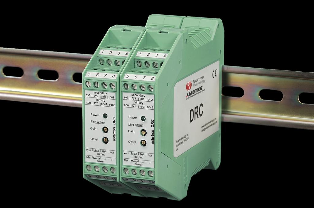
6 .0 Installation.1 Mounting and Access Before mounting the DRC, please refer to section Hook the DRC on the DIN rail with the release clip facing down and push onto the rail until a click is heard. To remove, use a screwdriver to lever the release clip down. Pull the bottom of the housing away from the rail and unhook. DRC 1 2 DRC DIN Rail Cover release latch Withdraw PCB To access internal links, the front cover and PCB must be withdrawn from the housing. Use a screwdriver or similar tool to depress the top latch. The cover will spring forward. Repeat with the bottom latch, then gently pull the PCB out..0 Installation 5
7 .0 Installation (cont.).2 Connections and link identification sy1 sy2 pri1 pri2 5 8 scn CT sec1 sec2 Power Fine Adjust Gain Offset Vout Mout 0V Iout 9 output 12 Min Mout# + 1 power 16 Transducer 1 Synchronisation 1 2 Synchronisation 2 Primary (red) Primary (blue) 5 Screen (0 V) 6 CT (yellow) 7 Secondary (green) 8 Secondary (white) Power Supply & Outputs 9 Voltage Output 10 Math OUT 11 Signal 0 V 12 Current OUT 1 Math External IN 1 Inverted Math OUT 15 VE power supply 16 +VE power supply Primary Frequency Synchronisation Coarse Offset Input Load Input Gain Coarse Gain Bandwidth Null at set-up A B C Option 1 : 5, 10, 1 Option 2 :, 5, Maths.0 Installation (cont.) Terminals 5, 11, and 15 are internally connected but, for best performance, they should be treated as separate terminals. Note: If the output polarity is incorrect, reverse the transducer secondary connections. 6
8 .0 Installation (cont.). Description of links The table below and subsequent diagrams explain the link functions and detail the factory settings. Link Description Options Factory Setting COARSE GAIN Select coarse output gain Range 1 to 6 Link ON, position 1 COARSE OFFSET Select coarse output offset +VE, -VE, 5 V, 10 V No offset, links PARKED NULL Used during set-up to null output Output in null state or enabled Link PARKED, output enabled PRIMARY Select primary frequency Option 1 : 5 khz, 10 khz, 1 khz Option 2 : khz, 5 khz, 10 khz Option 1 : Both links ON, 5 khz Option 2 : Both links ON, khz MT Select synchronisation mode Master or track Set as master INPUT LOAD Select transducer secondary load 100 kw or 2 kw Link PARKED, 100 kw INPUT GAIN Input gain X1, X2, X5, DIV2 Link ON, X1 BW Sets output signal bandwidth Option 1 : L = 500 Hz, H = 1 khz Option 2 : L = 250 Hz, H = 500 khz Option 1 : Link ON, 500 Hz Option 2 : Link ON, 250 Hz MATH Enables maths option A+B, A-B, (A+B)/2, (A-B)/2 Links PARKED, maths not set Note: If the output polarity is incorrect, reverse the transducer secondary connections. Link ON Link PARKED Link OFF.0 Installation (cont.) 7
9 .0 Installation (cont.). Primary Frequency The DRC primary frequency is set using links as shown below. Transducer specifications determine the optimum frequency. Primary amplitude is not adjustable. The DRC uses ratiometric techniques and is insensitive to primary amplitude. Maximum secondary transducer amplitudes must be observed. Refer to section Transducer Input Load The DRC has two input load ranges. 100 kω is often used for LVDT transducers while 2 kω is often used for Half Bridge transducers. If loads of less than 100 kω are required, an external resistor may be wired across the SEC1 and SEC2 terminals. Most Solartron transducers perform well into 100 kω. See specification section 7.2 for further details. 100 kω - link PARKED 2 kω - link ON Option 1 : Option 2 : M T 1 2 Option 1 : 5 khz khz khz 1 khz Option 2 : khz 5 khz 10 khz.6 Bandwidth The DRC has selectable bandwidth (BW). The bandwidth setting is independent of other DRC settings. Where possible, the lowest bandwidth setting should be used to minimise output noise. Option 1 Option Hz 250 Hz Link ON 1 khz 500 Hz Linked PARKED Note: Total system bandwidth is dependent on probe type and application Installation (cont.) 8
10 .0 Installation (cont.).7 Basic Configuration Please refer to section 2.10 before installation. A floating output power supply is recommended as it will minimise ground loop noise problems. Please refer to section 6.1 for a typical arrangement. pri Vout pri2 sec1 CT 7 6 Transducer Output 12 Iout + Voltage Current + - sec2 8 - screen 5 0V (GND) 11 0V (GND) Power Supply 10-0 VDC V (GND) Power converter Math Min Mout Mout# Voltage and current connections are shown. Generally only one type is used..0 Installation (cont.) 9
11 .0 Installation (cont.).8 Output Descriptions This section describes how the various outputs of the DRC are related. Vout This is a voltage output. The gain and offset controls are used to set the required output range. All other outputs are affected by changes made to Vout..0 Installation (cont.) 10 + Offsets Iout This is a current output only, DRC is not loop powered. This can be set for up to ±20 ma. A common output is -20 ma. The Iout is proportional to Vout but cannot be independently adjusted. The approximate relationship is shown below: Mout Mout# Input Gain Coarse Gain Transducer Circuits Voltage (V) Current (ma) When relating current to voltage, -20 ma is the same as a 2 to 10 V span (or ± V with a +6 V offset). Mout is the main MATH output. This is a voltage output. Vout and Min are combined in the MATH section. The output of this section is inverted to keep the signal polarity the same as Vout. This is an auxiliary voltage output. This is the direct output of the MATH stage and is the inverse of Vout. If MATH options are not selected then Mout Mout# Vout. Refer to section.1. All outputs may be used at the same time but cannot be independently adjusted for scalefactor or offset. - Min Fine Gain I V MATH Vout Iout Mout# Mout -1-1
12 .0 Installation (cont.).9 Connections The diagram in section 2.7 shows a basic connection with LVDT. The following diagram gives further details of Solartron LVDT transducers and alternative connections for Half Bridge transducers. LVDT Option 1 Pri1 (red) Pri2 (blue) Sec1 (green) CT (yellow) Sec2 (white) screen Option 2 Yel E Brn F Red A (Blu+Grn B+C) Bk D 0 V (GND) Half-Bridge LINK Pri1 (red) Pri2 (blue) Sec1 (yellow) Screen CT Sec V (GND) LVDT Electrical Connections Red and blue Primary (energising) Green and white Secondary (signal) Yellow Secondary centre tap Black Transducer body ground Half Bridge Electrical Connections Red and blue Energising Yellow Signal Black Transducer body ground The CT terminal is provided to terminate the centre tap (CT) connection of a transducer if present. There is no electrical connection within the DRC. This is provided to allow for quadrature components to be fitted if required..0 Installation (cont.) 11
13 .0 Installation (cont.).10 Placement and EMC DRC has been designed to comply with EMC regulations. For best performance, the EMC compliance of surrounding equipment must be considered. High levels of EMI (electro magnetic interference) can affect the performance of DRC. Residential, Commercial and Light Industrial Environments Typically this will be an office, laboratory or industrial environment where there is no equipment likely to produce high levels of electrical interference such as welders or machine tools. Connections may be made using twisted unscreened wire which is a costeffective option giving good performance in this environment. Standard equipment wire such as 7/0.2 (2AWG) can be twisted together as required. Standard data cable such as a generic CAT5 UTP will also give good performance. Industrial Environments Typically this will be an industrial environment where there is equipment likely to produce high levels of electrical interference such as welders, large machine tools, cutting or stamping machines. DRC should be mounted inside an industrial steel enclosure designed for EMI screening. Many enclosures, though metal, are not designed for good screening and so careful installation is important. Place DRC away from equipment within the enclosure that is likely to produce high levels of EMI. Connections should be made using a screened cable (braided or foil screened cables may be used). The cable screen should be connected to the housing at the cable entry point. An EMC cable gland is recommended. If this is not possible, then the unscreened section of cable should be kept as short as possible, and the screen should be connected to a local ground. Where possible, the DRC should be the only ground connection point. If voltage, current or power supplies are ground referenced and connected at some distance from DRC, then noise may be introduced. All 0 V terminals on DRC are connected internally. Ground 2 may be connected to any of the DRC 0 V terminals, however terminal 11 is preferred. Screen ground (ground 1) may be connected via terminal 11. Only one local ground is needed for each DRC. A local power supply is ideal but, if this is not possible, a screened cable arrangement can be used to reduce noise picked up. An application note outlining good practice for cable installation and routing is available from Installation (cont.) 12
14 .0 Installation (cont.) Keep exposed cable as short as possible Ground 1 and 2 DRC Keep exposed cable as short as possible Connect screen to chassis ground EMC gland Enclosure Ground 2 DRC.0 Installation (cont.) 1 Ground 1
15 .0 Installation (cont.) Transducer pri1 pri2 sec1 7 Sy1 Sy2 1 2 Transducer Output 9 12 Vout Ground 1 Voltage + - CT 6 sec2 8 screen 5 0V (GND) 11 0V (GND) Ground 2 Power supply V (GND) Power converter Math Min Mout Mout#.0 Installation (cont.) 1
16 .0 Installation (cont.).11 DRC Synchronisation When a system comprises several DRC modules, it is possible to synchronise primary oscillator phases. Synchronisation will not be required for most installations. It is only required when transducers and their cables are installed in close proximity to each other and there may be electrical interaction or cross-talk between probes. This may be seen as a change in output from one module when the probe connected to an adjacent module is moved. Even when probes are installed close to each other, synchronisation may not be required as cable shielding is generally effective. If interactions are seen, the cause is often poor 0 V or screen connection or mechanical effects between probes when mounted together. PCB Idents Option 1: Option 2: M T Link Positions (Primary links not shown).0 Installation (cont.) 15 MASTER TRACK
17 .0 Setting Up.1 Set-up Summary This is a set-up summary. A more detailed procedure is included in following sections but these simple steps describe a typical setting procedure and apply to most applications. Other procedures may be used as appropriate..0 Setting Up Step 1 Step 2 Step Step Step 5 Set links as required* Primary frequency Transducer load Initial gain Bandwidth No offset* No MATH* Set DRC output to zero Move transducer to full scale position Align transducer null Set DRC coarse and fine gain 16 Add offset if required Set DRC coarse and fine offset Final checks Repeat steps 2 - to check setting *If in doubt about initial link position, use the factory setting. Performing initial set-up without offset and MATH options makes set-up easier. Note: If the output polarity is incorrect, reverse the transducer secondary connections. For a bi-polar output i.e. ±10 VDC or ±20 ma, follow steps 1 to. Null For a uni-polar output i.e VDC, 0-20 ma or -20 ma, follow steps 1 to. In either case, step 5 (final checks) should be followed to complete the set-up. Zero electronics transducer -5V Zero +5V electronics transducer Null Shift zero 0V +5V +10V transducer Null electronics
18 .0 Setting Up (cont.).2 Set-up Procedure Step 1 - Set-up DRC links If the transducer characteristics are known, set the frequency and input resistance links as required. A list of standard settings for all Solartron transducers is available from If the transducer characteristics are not known, the factory link settings should be used. If the transducer is known to be outside the standard sensitivity range, the X1, X2, X5 or DIV2 links will have to be used. Please refer to section 5.1 Step 2 - Align DRC and transducer null Any electrical offset in the DRC is removed. The transducer position is adjusted so that transducer and DRC nulls are aligned. Null the DRC 1 Put the gain link onto the null position. This puts a temporary short across the transducer input and allows any electronics offset to be removed 2 Adjust the fine offset control to give as near zero output as practical Null the transducer Replace the gain link to the original position Adjust the position of the transducer to give as near zero output as practical. This is the centre of the mechanical range If the transducer cannot be centered for practical reasons, an offset will remain within the system. There may be noticeable interaction between gain and offset adjustment. This does not prevent the DRC being set-up, although several iterations may be required when adjusting gain and offset. Please consult your supplier for guidance if required..0 Setting Up (cont.) 17
19 .0 Setting Up (cont.) Step - Setting bi-polar (±) full scale output 1 Move the transducer to the position where maximum DRC output is required 2 If the output polarity is wrong, reverse the transducer secondary connections (terminals 7 & 8). Move the transducer back and re-check the zero position Move the coarse gain link along from position 1 towards position 6 until the DRC output is near the required value Adjust the fine gain control to give the required output 5 The bi-polar output is now set. Proceed to step 5 If a uni-polar output is required proceed to step. Example: ±10 V is required from a ±1 mm transducer. Set the transducer at the +1 mm position and set the output to +10 V. Step - Setting uni-polar full scale output (adding an offset) 1 Move the transducer to the null position. DRC output will be 0 V or 0 ma 2 Apply offset using the +VE, -VE, 5 V and 10 V links and adjust the fine offset control to set precisely. Both links may be used to give greater offset shift. Proceed to step 5 Example: 0-10 V is required for a ±1 mm transducer. Set the transducer to give ±5 V over the full range and then, with the transducer at null, add +5 V offset. Adjust the fine offset to give 5 V. When the transducer is moved to the +1 mm position, the output will be +10 V. Example: -20 ma is required for a ±1 mm transducer. Set the transducer to give ±8 ma over range and then, with the transducer at null, add +5 V ( 10 ma) offset. Adjust the fine offset to give +12 ma. When the transducer is moved to the +1 mm position, the output will be +20 ma. Step 5 - Final checks Ensure that calibration is correct by moving the transducer across the required mechanical range (including the mid position) and checking the calibration points. Fine adjustments can be made if required. It may only be possible to set the output accurately at the two calibration points. This is due to non-linearity within the transducer..0 Setting Up (cont.) 18
20 5.0 MATH Functions 5.1 MATH Introduction By linking two DRC modules, the following analogue arithmetic may be performed: A+B, A-B, (A+B)/2 and (A-B)/2. The output of DRC A, Vout A, is connected to the Min terminal of DRC B. The output of DRC B is routed internally to the arithmetic circuits and the result is available at the Mout terminal. The inverse of Mout is available as Mout#. Vout, Mout and Mout# may be used at the same time, however they are not individually adjustable Vout Vout Transducer A 7 Transducer Output 12 Iout Transducer B 7 Transducer Output 12 Iout DRC A No MATH link setting required Vout transducer A position Mout = Vout Mout# = 1/Mout = 1/Vout V (GND) Power Supply Math 11 0V (GND) Min Mout Mout# DRC B Math links set as A-B (example) Vout transducer B position Mout = Vout A - Vout B Mout# = 1/ Mout V (GND) Power Supply Math 11 0V (GND) Min Mout Mout# + V MATH Functions 19
21 5.0 MATH Functions (cont.) 5.2 MATH Set-up Procedure 1 2 A+B A-B LINK FOR (X)/ A+B A-B (A+B)/2 (A-B)/2 Mout=Vout Setting up two DRC for MATH can become confusing as the output of each DRC will affect the final output. The steps below are guidelines to help the set-up process. Step 1 - Requirements Write down the arithmetic required and the range of outputs likely to be seen. This will allow the requirement for each individual DRC to be determined. Vout of each DRC is used. Example: ±10 V required for A-B. If each DRC is set to ±10 V, then A-B would calculate to be ±20 V. However, as this is not possible, each DRC must be set to ±5 V or use ±10 V (A-B)/2. Example: 0-10 V required for A+B. Set each DRC for 0-5 V or set each DRC to 0-10 V and use (A+B)/2. Step 2 - Initial set-up Set up each DRC as an individual module first. Working around transducer null and having a ±V output will make set-up easier. Step - Final checks and further comments Initially each DRC Vout may have been set to an accurate zero but an offset may still be seen at Mout. This is because of offsets inherent within the MATH circuits. To remove this offset, adjust one of the Vout offsets. Mout offset adjustment is best performed on the DRC set for MATH. 5.0 MATH Functions (cont.) 20
22 6.0 Transducer Sensitivity 6.1 X1, X2, X5 and DIV2 link The DRC compensates for changes in primary signal amplitude by producing an internal error signal that is the ratio between the primary and secondary signals. If the transducer output signal is too high or too, low errors may occur that can degrade the performance of the DRC/transducer combination. For these transducers the X1, X2, X5 or DIV2 input gain link must be used. For Solartron transducers, consult the list of standard settings available from Calculating transducer Full Range Output (FRO) In general, transducer sensitivity is quoted as mv/v/mm where: mv = output of the transducer V = primary voltage mm = mechanical position of the transducer from null (usually mid mechanical range). To calculate the transducer full range output, simply multiply all three together. Example: AX/1.0 sensitivity is 210 mv/v/mm DRC primary voltage is V AX/1.0 range is ±1 mm Transducer full range output is 210 x x 1 = 60 mv (0.6 V). It falls within the standard range. Set the X1, X2, X5, DIV2 link as shown in the table below: Transducer Full Range Output Comment Input Gain Link setting 00 mv FRO to 2500 mv FRO Standard range Link ON X1 150 mv FRO to 00 mv FRO Low output transducer Link ON X2 150 mv FRO to 00 mv FRO Very low output transducer Link ON X mv FRO to 5000 mv FRO High output transducer DIV2 - Links X1, X2, X5 parked (ie. all OFF) 6.0 Transducer Sensitivity 21
23 AUTO A TO 7.0 Application 7.1 Application example Probe B Probe A Phoenix Contact MINI_PS power supply shown O T 2V C sy1 sy2 pri1 pri2 sy1 sy2 pri1 pri scn sec2 scn sec2 CT sec1 CT sec1 Power Power DRC B set to A-B Actual installation may differ depending on requirements. This is one practical example. Fine Adjust Gain Offset Fine Adjust Gain Offset DVM = probe A - probe B I VAC C C Vout Mout 0V Iout Vout Mout 0V Iout output 12 output Min Mout# - + Min Mout# power + 16 power Chassis/Ground i o i G uar d V A Vdc Vac Idc Iac Mains in DRC A DRC B DRC A linked to DRC B 7.0 Application 22
24 8.0 Specification 8.1 Mechanical Outline (mm) DRC 99.0 Solartron Metrology Ltd. Bognor Regis PO22 9ST UK Specification 2
25 8.0 Specification (cont.) 8.2 Technical Specification Power Requirement Voltage Range Current Range Transducer Excitation Primary Voltage 10 to 0 VDC 160 ma at 10 V to 70 ma at 0 V V rms nominal Primary Frequency Link Selectable Option 1 : 5 khz, 10 khz or 1 khz Option 2 : khz, 5 khz or 10 khz Primary Current 0 ma max. Signal Input (Transducer Sensitivity Range) Gain Range Link Select Standard X1 Special input gain X2 Special input gain X5 Special input gain DIV2 00 to 2500 mv FRO (in 6 gain ranges) 150 to 00 mv FRO 55 to 150 mv FRO 2500 to 5000 mv FRO Input Load Resistance 100 kw, 2 kw 1 Options See note 2 Signal Output Voltage Output Up to ±10 VDC, Current Output Up to ±20 ma into 500 W load Output Ripple Output Offset Up to 100% (coarse & fine adjustment) <1 mv rms Coarse (link selectable) Fine (front panel adjust) ±10 VDC ( 20 ma), ±5 VDC ( 10 ma) ±2.5 VDC ( 5.6 ma) 8.0 Specification (cont.) 2
26 8.0 Specification (cont.) Signal Output (cont.) Temp. Co. Gain Temp. Co. Offset Warm-up Linearity <0.01% FRO/ºC <0.01% FRO/ºC 15 minutes recommended <0.1% FRO Bandwidth (- db) Link Selectable Option 1 : 500 Hz, 1 khz Option 2 : 250 Hz, 500 Hz Maths Link Selectable A + B, A - B, (A +B)/2, (A - B)/2 5 Maths Accuracy Environmental Operational Temperature Range Storage Temperature Range Certification 0.1% FRO 0 to 60ºC (2 to 10ºF) -20 to 85ºC (- to 185ºF) Immunity BS EN :2001 Immunity for Industrial Environments 6 Emissions Mechanical and Connections Transducer Power Supply Output Signal Enclosure (size) Weight Material BS EN :2001 Emission for Residential, Commercial and Light-Industrial Environments 6 Screw terminals Screw terminals Screw terminals 11.5 x 99 x 22.5 mm 120 g Green polyamide 8.0 Specification (cont.) 25
27 8.0 Specification (cont.) Notes 1 Solartron Transducers are calibrated using the following loads: Standardised (plugged) Non-standardised (unplugged) Displacement LVDT 10 kw 100 kw 100 kw Half Bridge 2 kw 1 kw n/a When a standard LVDT transducer is connected to DRC set for 100 kw, transducer characteristics will be similar to the nonstandardised (unplugged) version of that transducer. When a non-standardised (unplugged) Half Bridge transducer is connected to DRC set for 2 kw, transducer characteristics will be similar to the standardised (plugged) version of that transducer. Any difference in transducer sensitivity is removed during DRC set-up. Where load resistance is critical, an external resistor may be fitted. If a 10 kw load is required an additional 11 kw resistor may be may be used in conjunction with the 100 kw internal load. This may be connected across the SEC1 (7) and SEC2 (8) terminals. If a 1 kw load is required, an additional 1 kw resistor may be used. 2 No input options are offered. As connection of transducer is by screw terminal, additional internal configuration methods are not required. By changing connections and use of external components, the user can perform: Change input polarity Half Bridge connection Grounding one side of the input Phase correction Quad resistors. DRC can drive into a 1 kw load but this offers no advantage kw is recommended. 8.0 Specification (cont.) 26
28 8.0 Specification (cont.) Output range can be adjusted as required anywhere within this range by using a combination of gain and offset, for example: ±10 VDC, ±5 VDC, 0-5 VDC, 0-10 VDC, -20 ma. 5 Maths requires the use of a second DRC. An additional output offset may be seen at any of the MATH outputs. This is not specified as it is trimmed out during set-up. 6 The DRC is able to comply with the toughest electrical emissions and immunity regulations. Compliance requires proper installation according to the user manual. Compliance does not guarantee performance as the installation environment may be outside of test specification limits. The flexibility of DRC means it can be installed in a variety of ways according to user requirements. Simple installations with short non-screened cables will meet the lesser light-industrial immunity regulations. Heavy industrial installations, especially with longer cables, will need more careful installation with screened cables. 8.0 Specification (cont.) 27
LVC Low Voltage Conditioner. User Manual
 LVC - 2500 Low Voltage Conditioner User Manual Index 1.0 Safety Information 2.0 MATH Functions 18 1.1 Electrostatic discharge.1 MATH Introduction 18.2 MATH Set-up Procedure 19 2.0 Installation 2.1 Mounting
OD4 PRODUCT NAME. user manual. user manual. Conditioning Module. Product Type
 OD4 Conditioning Module PRODUCT NAME Product Type user manual user manual 1.0 Index Section Title Page 1.0 Index...................... 2 2.0 Safety Information............ 3 3.0 Introduction.................
CAH CARD. user leaflet. 1 of 15. Copyright Issue 12.1 January 2015
 CAH CARD user leaflet 1 of 15 INTRODUCTION The function of the card is to energise a transducer (LVDT, Half-Bridge or Full-Bridge) with a stable a.c. waveform and to convert the output of the transducer
User s Guide LDX-4. Shop online at omega.com. For latest product manuals:
 User s Guide Shop online at omega.com e-mail: info@omega.com For latest product manuals: www.omegamanual.info LDX-4 omega.com info@omega.com U.S.A. Headquarters: Servicing North America: Omega Engineering,
user leaflet ABSOLUTE TTL MODULE
 user leaflet ABSOLUTE TTL MODULE Product Description Introduction The Solartron ATM transducer comprises a sensor and conditioning electronics which provides an RS422 level square wave output. Each output
Technical Manual TRANSDUCER AMPLIFIER TYPE DR7AC. Doc. Ref CD2402K
 RDP CUSTOMER DOCUMENT Technical Manual TRANSDUCER AMPLIFIER TYPE DR7AC Doc. Ref CD2402K BS EN ISO 9001 Certificate No. FM13141 Affirmed by Declaration of Conformity USA & Canada RDP Electrosense Inc. 2216
user leaflet BICM - LVDT (Boxed Inline Conditioning Module) For LVDT Transducers only
 For LVDT Transducers only") user leaflet BICM - LVDT (Boxed Inline Conditioning Module) For LVDT Transducers only Index Section Title Page Index.......................... 1 1.0 Introduction................. 2 2.0 Technical Specification...............
user leaflet BICM - LVDT (Boxed Inline Conditioning Module) For LVDT Transducers only Index Section Title Page Index.......................... 1 1.0 Introduction................. 2 2.0 Technical Specification...............
TECHNICAL MANUAL. SERIES AP5202 DC Strain Gage In-Line Amplifier ISO 9001/AS9100
 TECHNICAL MANUAL SERIES AP5202 DC Strain Gage In-Line Amplifier ISO 9001/AS9100 Due to the nature of technology, changes are inevitable. For latest technical specifications, see our website. Copyright
Technical Manual TRANSDUCER AMPLIFIER TYPE S7AC. Doc. Ref CD1201T
 RDP CUSTOMER DOCUMENT Technical Manual TRANSDUCER AMPLIFIER TYPE S7AC Doc. Ref CD1201T This manual applies to units of mod status 4 ONWARDS BS EN ISO 9001 / 1994 Certificate No. FM13141 Affirmed by Declaration
WS12EX Position Sensor with Analog output Dust explosion-proof
 Sensor for Hostile Environments Class IP67 Measurement Range: 0... 100 mm to 0... 3000 mm With Analog Output Dust Ex proof, category 3, zone 22 II 3D EEx T80 C IP67 Specifications Outputs Material Resolution
MODEL AT-10 ANALOG TRANSMITTER
 MODEL AT-10 ANALOG TRANSMITTER INSTALLATION & OPERATING MANUAL Industrial Weighing Systems 9 Richmond Street Picton, Ontario K0K 2T0 Phone: 613-921-0397 Fax: 613-476-5293 Web: www.iwsystems.ca info@iwsystems.ca
INSTALATION, OPERATION & MAINTENANCE MANUAL. PA-1001A Series SIGNAL CONDITIONER & CONVERTORS
 INSTALATION, OPERATION & MAINTENANCE MANUAL FOR PA-1001A Series SIGNAL CONDITIONER & CONVERTORS PA1001A 7/02 Page 1 of 11 SIGNAL CONDITIONER & CONVERTERS PA1001A Series INTRODUCTION: The PA1001A series
Technical Manual TRANSDUCER AMPLIFIER TYPE S7TW. Doc. Ref CD1210W
 RDP CUSTOMER DOCUMENT Technical Manual TRANSDUCER AMPLIFIER TYPE S7TW Doc. Ref CD1210W This manual applies to units of mod status 13 ONWARDS BS EN ISO 9001 Certificate No. FM13141 Affirmed by Declaration
SEM104 SERIES. SEM104P Pt100 Temperature Transmitter. SEM104TC Thermocouple Temperature Transmitter INDEX SECTION CONTENTS PAGE NO.
 INDEX SECTION CONTENTS PAGE NO. SEM104 SERIES SEM104P Pt100 Temperature Transmitter SEM104TC Thermocouple Temperature Transmitter SEM104P 1 1.0 DESCRIPTION 2 2.0 SPECIFICATION 2 3.0 INSTALLATION 24 4.0
For ultra-high precision measurement of current: DC, AC, pulsed..., with galvanic separation between primary and secondary. Applications.
 Current Transducer IT 205-S ULTRASTAB I PN = 200 A For ultra-high precision measurement of current: DC, AC, pulsed..., with galvanic separation between primary and secondary. Features Wide operating temperature
Isolated High Level Voltage Output 7B22 FEATURES APPLICATIONS PRODUCT OVERVIEW FUNCTIONAL BLOCK DIAGRAM
 Isolated High Level Voltage Output 7B22 FEATURES Unity gain single-channel signal conditioning output module. Interfaces and filters a +10 V input signal and provides an isolated precision output of +10V.
For ultra-high precision measurement of current: DC, AC, pulsed..., with galvanic separation between primary and secondary. Applications.
 Current Transducer IT 200-S ULTRASTAB I PM = 200 A For ultra-high precision measurement of current: DC, AC, pulsed..., with galvanic separation between primary and secondary. Features Closed loop (compensated)
Instruction Manual MSC710 MSC710-U MSC710-I
 Instruction Manual MSC710 MSC710-U MSC710-I Sensor controller for inductive displacement and gauging sensors series LVDT MICRO-EPSILON MESSTECHNIK GmbH & Co. KG Koenigbacher Strasse 15 94496 Ortenburg
SC200 Series. Signal Conditioner MNX10020, REV H 10/17/ Connection Technology Center, Inc Rae Boulevard Victor, NY (585)
") SC200 Series Signal Conditioner MNX10020, REV H 10/17/2012 1 CONTENTS SECTION 1: OVERVIEW... 4 Introduction... 4 Description... 4 Ordering Information... 4 Specifications... 5 Environmental... 5 Electrical...
SC200 Series Signal Conditioner MNX10020, REV H 10/17/2012 1 CONTENTS SECTION 1: OVERVIEW... 4 Introduction... 4 Description... 4 Ordering Information... 4 Specifications... 5 Environmental... 5 Electrical...
For ultra-high precision measurement of current: DC, AC, pulsed..., with galvanic separation between primary and secondary. Applications.
 Current Transducer IT 605-S ULTRASTAB I PN = 600 A For ultra-high precision measurement of current: DC, AC, pulsed..., with galvanic separation between primary and secondary. Features Wide operating temperature
Section 1, General information Introduction... 3 Description... 3 Specifications... 4 Wiring connections... 5
 LIST OF CONTENTS Section 1, General information Introduction... 3 Description... 3 Specifications... 4 Wiring connections... 5 Section 2, Calibration Calculations... 7 Calibration Procedure... 8 Section
MCR-VAC-UI-0-DC. Voltage transducer for AC voltages. INTERFACE Data sheet _en_02. 1 Description
 Voltage transducer for AC voltages TERFACE Data sheet 006_en_0 PHOENIX CONTACT 00-0- Description The MCR voltage transducer measures AC voltages in several signal ranges from 0... ±4 V AC to 0... ±30 V
For the electronic measurement of current: DC, AC, pulsed..., with galvanic separation between the primary and the secondary circuit.
 Current Transducer IN 1000-S N = 1000 A For the electronic measurement of current: DC, AC, pulsed..., with galvanic separation between the primary and the secondary circuit. Features Closed loop (compensated)
Isolated, Linearized RTD Input 7B34 FEATURES APPLICATIONS PRODUCT OVERVIEW FUNCTIONAL BLOCK DIAGRAM
 Isolated, Linearized RTD Input 7B34 FEATURES Amplifies, Protects, Filters, and interfaces input voltages from a wide variety of two and three-wire platinum, copper and nickel Resistor Temperature Detectors
High Performance Current Transducer IT 200-S ULTRASTAB = A. ε L
 High Performance Current Transducer IT 200-S ULTRASTAB For the electronic measurement of currents: DC, AC, pulsed..., with galvanic isolation between the primary circuit and the secondary circuit. I PM
Ref: HO 50-S/SP33, HO 100-S/SP33, HO 150-S/SP33, HO 200-S/SP33, HO 250-S/SP33
 Current Transducer HO-S/SP33 series I PN = 50, 100, 150, 200, 250 A Ref: HO 50-S/SP33, HO 100-S/SP33, HO 150-S/SP33, HO 200-S/SP33, HO 250-S/SP33 For the electronic measurement of current: DC, AC, pulsed...,
400 (±2,5 V/ V/ ,3% V4A
 LVDT Inductive Position Transducer - Hydraulic Series Series Hydraulic position measurement in hydraulic cylinders of machine controls ranges 10...300 mm temperature -40...+150 C (sensors) 0...+60 C (external
Transducer transmitter BILT 4 II 2(1) G. Technical Manual
 G. Technical Manual") GB Transducer transmitter BILT 4 II 2(1) G Technical Manual Transducer transmitter BILT 4 Contents Introduction General... 3 Ex.safety description... 4 Technical data... 5 Installation General... 6 Mechanical
GB Transducer transmitter BILT 4 II 2(1) G Technical Manual Transducer transmitter BILT 4 Contents Introduction General... 3 Ex.safety description... 4 Technical data... 5 Installation General... 6 Mechanical
IF30. User's manual. Description. Table of contents IF30
 User's manual IF30 Description IF30 is an encoder interface unit designed to convert the output signals delivered by so-called sine-cosine-encoders and similar measuring systems (devices which deliver
For the electronic measurement of current: DC, AC, pulsed..., with galvanic separation between the primary and the secondary circuit.
 Current Transducer IN 1000-S I P N = 1000 A For the electronic measurement of current: DC, AC, pulsed..., with galvanic separation between the primary and the secondary circuit. Features Closed loop (compensated)
Isolated, Linearized Thermocouple Input 7B47 FEATURES APPLICATIONS PRODUCT OVERVIEW FUNCTIONAL BLOCK DIAGRAM
 Isolated, Linearized Thermocouple Input 7B47 FEATURES Interfaces, amplifies and filters input voltages from a J, K, T, E, R, S, B or N-type thermocouple. Module provides a precision output of either +1
Isolated, Thermocouple Input 7B37 FEATURES APPLICATIONS PRODUCT OVERVIEW FUNCTIONAL BLOCK DIAGRAM
 Isolated, Thermocouple Input 7B37 FEATURES Interfaces, amplifies, and filters input voltages from a J, K, T, E, R, S, or B-type thermocouple. Module provides a precision output of either +1 V to +5 V or
OPERATION MANUAL LDM-1000
 OPERATION MANUAL LDM-1000 TE CONNECTIVITY SENSORS /// LDM-1000 OPERATION MANUAL P/N 09290100-000 REV. C 05/2016 Page 1 Table of Contents 1. Introduction...3 2. Product Specifications...3 3. Product Description...4
For ultra-high precision measurement of current: DC, AC, pulsed..., with galvanic separation between primary and secondary. Applications.
 Current Transducer ITN 1000-S ULTRASTAB I PM = 1000 A For ultra-high precision measurement of current: DC, AC, pulsed..., with galvanic separation between primary and secondary. Features Closed loop (compensated)
User's Manual: Series 450T AC Current Input (External Sensor), AC-Powered Transmitters
, AC-Powered Transmitters") User's Manual: Series 450T AC Current Input (External Sensor), AC-Powered Transmitters Table of Contents Page Introduction 1 Description 1 Specifications 2 Installation 3 Calibration 4 General Maintenance
User's Manual: Series 450T AC Current Input (External Sensor), AC-Powered Transmitters Table of Contents Page Introduction 1 Description 1 Specifications 2 Installation 3 Calibration 4 General Maintenance
TT-SI MHz Active Differential Probe
 INSTRUCTION MANUAL TT-SI 9110 100MHz Active Differential Probe These probe is in compliance with EN61010-031:2002+A1:2008 CAT III, Pollution Degree 2 1. Safety Terms and Symbols Terms appear in this manual:
MCR-C-UI-UI-DCI MCR 3-Way Isolation Amplifier, Configurable
 MCR-C-UI-UI-DCI MCR 3-Way Isolation Amplifier, Configurable 1. Short description configurable inputs and outputs signal conversion/amplification 3-way-isolation zero/span adjustment 17.5 mm ME housing
IDEAL INDUSTRIES, INC. TECHNICAL MANUAL MODEL: MODEL: Multimeter Service Information
 IDEAL INDUSTRIES, INC. TECHNICAL MANUAL MODEL: 61-340 MODEL: 61-342 Multimeter Service Information The Service Information provides the following information: Precautions and safety information Specifications
Current Loop Interface Module M 2025D
 CONTROLS Current Loop Interface Module M 2025D Current-to-Voltage Analog Converter used with the M 2001 Series Digital Tapchanger Control and M-2948 Tap Position Sensors to provide positive tap position
Primary-standard resistance thermometry bridge Model CTR9000
 Calibration technology Primary-standard resistance thermometry bridge Model CTR9000 WIKA data sheet CT 60.80 Applications High-performance AC resistance thermometry bridge for very accurate temperature
For the electronic measurement of current: DC, AC, pulsed..., with galvanic separation between the primary and the secondary circuit.
 Current Transducer LF 1010-S/SPA5 I P N = 1000 A For the electronic measurement of current: DC, AC, pulsed..., with galvanic separation between the primary and the secondary circuit. Features Bipolar and
Ordercode Output Power Output 1 Output 2 Output 3 PCB-mounting Chassis mounting max. with solder pins with screw terminals
 Features PCB Mounting with Solder Pins or Chassis Mounting with Screw Terminals Single, Dual and Triple Output Models Universal Input 8-2 VAC, 0 0 Hz EMI meets EN 022, Class B and FCC, Level B Low Ripple
EPA-M*** POWER AMPLIFIER FOR OPEN LOOP PROPORTIONAL VALVES SERIES 20
 89 220/101 ED EPA-M*** POWER AMPLIFIER FOR OPEN LOOP PROPORTIONAL VALVES EPA-M1** single solenoid EPA-M2** double solenoid EPA-M3** 2 independent channels single solenoid valves RAIL MOUNTING TYPES: DIN
DC Current Transducers CT-200 CT-300 CT-400 User s Manual All Rights Reserved CAEN ELS d.o.o. Rev. 1.0 November 2014
 < DC Current Transducers CT-200 CT-300 CT-400 User s Manual PRECISION CURRENT TRANSDUCERS All Rights Reserved CAEN ELS d.o.o. Rev. 1.0 November 2014 CAEN ELS d.o.o. Kraška ulica, 2 6210 Sežana Slovenija
For ultra-high precision measurement of current: DC, AC, pulsed..., with galvanic separation between primary and secondary. Applications.
 Current Transducer IT 700-S ULTRASTAB I PM = 700 A For ultra-high precision measurement of current: DC, AC, pulsed..., with galvanic separation between primary and secondary. Features Closed loop (compensated)
For the electronic measurement of current: DC, AC, pulsed..., with galvanic separation between the primary and the secondary circuit.
 Current Transducer HO-NSM/SP33 series N = 8, 15, 25 A Ref: HO 8-NSM/SP33, HO 15-NSM/SP33, HO 25-NSM/SP33 For the electronic measurement of current: DC, AC, pulsed..., with galvanic separation between the
POSICHRON position sensor in stick design. Protection class. Voltage: V, 3 wire Current: ma, 3 wire
 POSICHRON Position Sensor Stick Design with Analog Specifications POSICHRON position sensor in stick design Protection class IP67 Measurement range 0... 100 up to 0... 5750 mm Absolute position measurement
Operation Manual for. Mag690 Three-Axis Fluxgate Magnetometer
 Operation Manual for Mag690 Three-Axis Fluxgate Magnetometer Table of Contents 1. About this Manual 4 1.1. Symbols Glossary 4 2. Safe Use 4 3. Introduction to the Mag690 4 3.1. Vector Measurements and
User's Manual: Series 350T AC Current Input (External Sensor), DC-Powered Transmitters
, DC-Powered Transmitters") User's Manual: Series 350T AC Current Input (External Sensor), DC-Powered Transmitters Table of Contents Page Introduction 1 Description 1 Specifications 2 Installation 3 Calibration 4 General Maintenance
User's Manual: Series 350T AC Current Input (External Sensor), DC-Powered Transmitters Table of Contents Page Introduction 1 Description 1 Specifications 2 Installation 3 Calibration 4 General Maintenance
MODEL: M2DYS SEN TRONIC AG
 Super-mini Signal Conditioners Mini-M Series CURRENT LOOP SUPPLY Functions & Features Powers a 20 ma DC current loop Short circuit protection Applicable to smart transmitters CE marking UL approval Typical
HO 50-S/SP30, HO 100-S/SP30, HO 150-S/SP30, HO 200-S/SP30, HO 250-S/SP30 and HO 200-S/SP31
 Current Transducer HO-S/SP3 series Ref: I PN = 5,, 15, 2, 25 A HO 5-S/SP3, HO -S/SP3, HO 15-S/SP3, HO 2-S/SP3, HO 25-S/SP3 For the electronic measurement of current: DC, AC, pulsed..., with galvanic separation
I PN. Ref: HO 50-S, HO 100-S, HO 150-S, HO 200-S, HO 240-S, HO 250-S
 Current Transducer HO-S series I PN = 50, 100, 150, 200, 240, 250 A Ref: HO 50-S, HO 100-S, HO 150-S, HO 200-S, HO 240-S, HO 250-S For the electronic measurement of current: DC, AC, pulsed..., with galvanic
Operation Manual for. Mag690 Three-Axis Fluxgate Magnetometer.
 Operation Manual for Mag690 Three-Axis Fluxgate Magnetometer www.bartingtondefenceandspace.com www.bartingtondefenceandspace.com Table of Contents 1. How to Use this Manual 3 1.1. Symbols Glossary 3 2.
For ultra-high precision measurement of current: DC, AC, pulsed..., with galvanic separation between primary and secondary. Applications.
 Current Transducer IT 700-SB ULTRASTAB I PM = 700 A For ultra-high precision measurement of current: DC, AC, pulsed..., with galvanic separation between primary and secondary. Features ± 10 V voltage output
For the electronic measurement of current: DC, AC, pulsed..., with galvanic separation between the primary and the secondary circuit.
 Current Transducer CAS 25-NP/SP2 N = 25 A For the electronic measurement of current: DC, AC, pulsed..., with galvanic separation between the primary and the secondary circuit. Features Closed loop (compensated)
DUAL OUTPUT AC CURRENT/VOLTAGE TRANSDUCER
 OPERATOR S MANUAL DUAL OUTPUT AC CURRENT/VOLTAGE TRANSDUCER Masibus Automation & Instrumentation Pvt. Ltd. B/30, GIDC Electronics Estate, Sector-25, Gandhinagar-382044, Gujarat, India Web Site: www..com
ICA User Manual ICA. ICA Embedded Strain Gauge Analogue Amplifiers
 ICA User Manual ICA ICA Embedded Strain Gauge Analogue Amplifiers Contents Chapter 1 The ICA Range... 2 Figure 1.1 Block Diagram... 2 The ICA6H... 2 Chapter 2 Installing the ICA Range... 3 Pre Installation...
V P N. Voltage transducer DVM 2000-B = 2000 V
 Voltage transducer DVM 2-B V P N = 2 V For the electronic measurement of voltage: DC, AC, pulsed..., with galvanic separation between the primary and the secondary circuit. Features Bipolar and insulated
For the electronic measurement of current: DC, AC, pulsed..., with galvanic separation between the primary and secondary circuit.
 Current Transducer LF 510-S I P N = 500 A For the electronic measurement of current: DC, AC, pulsed..., with galvanic separation between the primary and secondary circuit. Features Bipolar and insulated
TECHNICAL DATASHEET #TD1400AX PWM Controlled Solenoid Driver (DIN rail mount) P/N: PWMC-DR-2A, PWMC-DR-1.2A
 P/N: PWMC-DR-2A, PWMC-DR-1.2A") TECHNICAL DATASHEET #TD1400AX PWM Controlled Solenoid Driver (DIN rail mount) P/N: PWMC-DR-2A, PWMC-DR-1.2A Description: The PWM Controlled Solenoid Driver supplies a proportional solenoid with current
TECHNICAL DATASHEET #TD1400AX PWM Controlled Solenoid Driver (DIN rail mount) P/N: PWMC-DR-2A, PWMC-DR-1.2A Description: The PWM Controlled Solenoid Driver supplies a proportional solenoid with current
TBX-1329 AC/DC COUPLING TERMINAL BLOCK
 INSTALLATION GUIDE TBX-1329 AC/DC COUPLING TERMINAL BLOCK Introduction This guide describes how to install and use the TBX-1329 AC/DC coupling terminal block with the SCXI-1120, SCXI-1120D, and SCXI-1121
MODEL: M2SES SEN TRONIC AG [3] OUTPUT
![MODEL: M2SES SEN TRONIC AG [3] OUTPUT](/thumbs/86/93838653.jpg "MODEL: M2SES SEN TRONIC AG [3] OUTPUT") Super-mini Signal Conditioners Mini-M Series HIGH/LOW SELECTOR Functions & Features Monitors two DC input signals and transmits an output signal proportional to the higher or lower input CE marking UL
Super-mini Signal Conditioners Mini-M Series HIGH/LOW SELECTOR Functions & Features Monitors two DC input signals and transmits an output signal proportional to the higher or lower input CE marking UL
The Harvard Research Carrier Signal Conditioner User s Manual
 The Harvard Research Carrier Signal Conditioner User s Manual TABLE OF CONTENTS SECTION TITLE PAGE I GENERAL INFORMATION INTRODUCTION 1.1 SPECIFICATIONS 1.1 II INSTALLATION 2.1 GENERAL 2.1 2.2 INITIAL
PRECISION CURRENT TRANSDUCERS. DC Current Transducers CT-100 CT-150. User s Manual. All Rights Reserved CAEN ELS d.o.o. Rev. 1.
 < DC Current Transducers CT-100 CT-150 User s Manual PRECISION CURRENT TRANSDUCERS All Rights Reserved CAEN ELS d.o.o. Rev. 1.1 November 2014 CAEN ELS d.o.o. Kraška ulica, 2 6210 Sežana Slovenija Mail:
Kattegat JP Groningen, The Netherlands High Efficiency High Power Audio SMPS
 Highlights High efficiency Selectable input voltage range Low EMI Features Advanced over current protection Remote controlled operation Low weight: 1,5kg Compact: 200 x 145 x 55mm Fixed output voltage
Current Transducer CTSR 1-P = 1A
 Current Transducer CTSR 1-P I PRN = 1A For the electronic measurement of current: DC, AC, pulsed..., with galvanic isolation between the primary (high power) and the secondary circuit (electronic circuit).
Protection Class (IEC 529)
") (W)GS2 Velocity Sensor with Analog or A/D converted synchronous serial output Specifications Velocity Sensor with Position Option Class IP50 Measurement Range: 0... 1500 mm to 0... 2500 mm 0... 59.06 in
(W)GS2 Velocity Sensor with Analog or A/D converted synchronous serial output Specifications Velocity Sensor with Position Option Class IP50 Measurement Range: 0... 1500 mm to 0... 2500 mm 0... 59.06 in
MODEL IFMA - DIN-RAIL FREQUENCY TO ANALOG CONVERTER
 H MODEL IFMA - DIN-RAIL FREQUENCY TO ANALOG CONVERTER SIMPLE ON-LINE RANGE SETTING (Using Actual Input Signal or Signal Generator) USER SETTABLE FULL SCALE FREQUENCY FROM 1 Hz to 25 KHz FOUR OUTPUT OPERATING
User s Manual for Integrator Short Pulse ISP16 10JUN2016
 User s Manual for Integrator Short Pulse ISP16 10JUN2016 Specifications Exceeding any of the Maximum Ratings and/or failing to follow any of the Warnings and/or Operating Instructions may result in damage
Transducer for Measurement Bridges SCM90, SIGS15
 Transducer for Measurement Bridges SCM90, SIGS15 General Description Transducer for measurement bridges for DINrails and for printed circuit boards. Programmable ranges and bridge supply, voltage or current
For the electronic measurement of current: DC, AC, pulsed..., with galvanic separation between the primary and the secondary circuit.
 Current Transducer HO-NSM- SERIES I PN = 8, 15, 25 A Ref: HO 8-NSM-, HO 15-NSM-, HO 25-NSM- For the electronic measurement of current: DC, AC, pulsed..., with galvanic separation between the primary and
W(G)S3.1 Position Sensor with Analog or A/D converted synchronous serial output
S3.1 Position Sensor with Analog or A/D converted synchronous serial output") W(G)S3.1 Position Sensor with Analog or A/D converted synchronous serial output Position and Velocity Sensor for Long Ranges Protection Class IP50 Measurement Range: 0... 10000 mm to 0... 15000 mm 0...
W(G)S3.1 Position Sensor with Analog or A/D converted synchronous serial output Position and Velocity Sensor for Long Ranges Protection Class IP50 Measurement Range: 0... 10000 mm to 0... 15000 mm 0...
MODEL SS - DIN-RAIL SPEED SWITCH
 MODEL SS - DIN-RAIL SPEED SWITCH! SIMPLE ON-LINE TRIP FREQUENCY SETTING (USING ACTUAL INPUT SIGNAL OR FREQUENCY GENERATOR)! USER SETTABLE TRIP FREQUENCY FROM 0.1 Hz to 25 KHz! OVER-SPEED, UNDER-SPEED,
AUTOMOTIVE CURRENT TRANSDUCER HAH3DR 700-S00
 AUTOMOTIVE CURRENT TRANSDUCER HAH3DR 700-S00 Introduction The HAH3DR family, a tri-phase tranducer is for the electronic measurement of DC, AC or pulsed s in high power automotive applications with galvanic
V P N. Voltage transducer DVM 4200 = 4200 V
 Voltage transducer DVM 42 N = 42 V For the electronic measurement of voltage: DC, AC, pulsed..., with galvanic separation between the primary and the secondary circuit. Features Bipolar and insulated measurement
GAMMA 20 DIGITAL MULTIMETER
 Gamma 20 www.sifamtinsley.co.uk DATASHEET Issue 1.0 Multifunction Meters Transducers & Isolators Temperature Controllers Converters & Recorders Digital Panel Meters Current Transformers Analogue Panel
MINI MCR-SL-UI-I-LP-NC
 2-way isolation amplifier Data sheet 105263_en_02 PHOENIX CONTACT 2013-12-13 1 Description The configurable 2-way isolation amplifiers are used to electrically isolate, convert and filter standard signals.
MODEL: W2DYS SEN TRONIC AG. Mini-MW Series
 MODEL: WDYS Space-saving Dual Output Signal Conditioners Mini-MW Series CURRENT LOOP SUPPLY Functions & Features Powers a 0 ma DC current loop Short circuit protection Applicable to smart transmitters
PRetrans Table of contents
 HART TRANSPARENT REPEATER PRetrans 5106 Table of contents Warnings 16 Safety instructions 17 EC Declaration of Conformity 19 How to demount SYSTEM 5000 20 Application 21 Technical characteristics 21 Mounting
Laboratory Equipment Instruction Manual 2011
 University of Toronto Department of Electrical and Computer Engineering Instrumentation Laboratory GB341 Laboratory Equipment Instruction Manual 2011 Page 1. Wires and Cables A-2 2. Protoboard A-3 3. DC
Heavy Duty Pressure Transducers. PX2 Series 1 bar to 46 bar 100 kpa to 4.6 MPa 15 psi to 667 psi. Datasheet
 PX2 Series bar to 46 bar 00 kpa to 4.6 MPa 5 psi to 667 psi Datasheet Table. Electrical Specifications Characteristic Ratiometric Regulated Transfer Function Order Code (See Figure 5.) AA AB AC AD CH BC
SEM210 SERIES. Programmable In-head Universal Temperature Transmitter INDEX SECTION CONTENTS PAGE NO.
 INDEX SECTION CONTENTS PAGE NO. SEM210 SERIES 1.0 DESCRIPTION 1 2.0 SPECIFICATION 15 3.0 INSTALLATION 67 Programmable Inhead Universal Temperature Transmitter Status Instruments Ltd, Green Lane Business
For the electronic measurement of current: DC, AC, pulsed..., with galvanic separation between the primary and the secondary circuit.
 Current transducer CKSR series N = 6, 5, 25, 5 A Ref: CKSR 6-NP, CKSR 5-NP, CKSR 25-NP, CKSR 5-NP For the electronic measurement of current: DC, AC, pulsed..., with galvanic separation between the primary
For the electronic measurement of current: DC, AC, pulsed..., with galvanic separation between the primary and the secondary circuit.
 Current Transducer HO-NP series I PN = 4, 6, 12, 15 Ref: HO 4-NP, HO 6-NP, HO 12-NP, HO 15-NP For the electronic measurement of current: DC, C, pulsed..., with galvanic separation between the primary and
CPCO Series DC-AC Current Probe, Clamp On, 160mm, ±1000A ±2000A ±4000A ±8000A ±12000A, ±16000A
 The CPCO Series (160mm aperture) Current Probes are Clamp On current sensors capable of measuring ac and dc currents. The Current Probe splits along a diameter allowing easy installation to existing cables
SY038 UNIVERSAL LOAD CELL AMPLIFIER
 SY038_manual_V2.0_2017_04_04 Interface Force Measurements Ltd. SY038 UNIVERSAL LOAD CELL AMPLIFIER Introduction The SY038 is a DIN rail mounted amplifier that converts a mv input signal typically from
Model LIA100. Lock-in Amplifier
 Model LIA100 Lock-in Amplifier Operations Manual Thorlabs, Inc 435 Route 206 Newton, NJ 07860 P-(973) 579-7227 F-(973) 300-3600 www.thorlabs.com Doc. Page 1 of 10 Table of Contents Chapter Description
SCC-FV01 Frequency Input Module
 USER GUIDE SCC-FV01 Frequency Input Module Conventions The SCC-FV01 frequency input module is a frequency-to-voltage converter designed to measure signals from frequency-generating sensors and other periodic
EMC Data Sheet CSD100 Model size 4 to 6. Variable Speed AC drive for permanent magnet motors
 EMC Data Sheet CSD100 Model size 4 to 6 Variable Speed AC drive for permanent magnet motors Safety Warnings A Warning contains information which is essential for avoiding a safety hazard. A Caution contains
MINI MCR-SL-UI-f(-SP)
") Configurable Analog Frequency Transducer INTERFACE Data Sheet PHOENIX CONTACT - 02/2006 Description The configurable analog frequency transducer MINI MCR-SL-UI-f(-SP) is used to convert analog standard
Configurable Analog Frequency Transducer INTERFACE Data Sheet PHOENIX CONTACT - 02/2006 Description The configurable analog frequency transducer MINI MCR-SL-UI-f(-SP) is used to convert analog standard
AUTOMOTIVE CURRENT TRANSDUCER HAH3DR 700-S02
 AUTOMOTIVE CURRENT TRANSDUCER Introduction The HAH3DR family, a tri-phase tranducer is for the electronic measurement of DC, AC or pulsed s in high power automotive applications with galvanic isolation
I P I OUT R L. Applications. Standards. N 52.D ; Page 1/8
 Ref: ATO-10-B225-D10/SP3 r = 10 A ATO series is a split core current transformer for the electronic measurement of AC waveform current with galvanic separation between the primary circuit (power) and the
For the electronic measurement of current: DC, AC, pulsed..., with galvanic separation between the primary and the secondary circuit.
 Current Transducer LF 2010-S/SPA7 I P N = 2000 A For the electronic measurement of current: DC, AC, pulsed..., with galvanic separation between the primary and the secondary circuit. Features Bipolar and
McPherson Voltage Regulators 4501 NW 27 Ave Miami FL
 McPherson Voltage Regulators 4501 NW 27 Ave Miami FL 33142 305-634-1511 To avoid of possible personal injury or equipment damage read and understand this manual before installation. (A.V.R) 208 / 380 /
Mid-West. Instrument. Model 140 Electrical Installation and Operating Instructions. Gauge Front ELECTRICAL
 Mid-West Instrument BULLETIN NO. ELEC-IM140/11A Replaces ELEC-IM140-141/09A ELECTRICAL Gauges with switches have one or two SPST or SPDT hermetically sealed adjustable set point reed switch assemblies.
POSICHRON position sensor in a stainless steel pressure case. Voltage: V, 3 wire Current: ma, 3 wire
 Rod Profile with Analog Specifications POSICHRON position sensor in a stainless steel pressure case Protection class IP68 Compression-proof up to 15 bar Measurement range 0... 100 to 0... 5750 mm Absolute
AC/DC Power Supply Series APPLICATION NOTE
 -350 + -700 AC/DC Power Supply Series APPLICATION NOTE NV350_NV700 App notes 69498 12.doc Document Number 69498 Page 1 of 17 1. INPUT... 3 AC INPUT LINE REQUIREMENTS... 3 2. DC OUTPUT... 3 OUTPUT VOLTAGES...
BL series Miniature paddle joystick controllers
 Distinctive features and specifications Hall effect joystick and switch function Sculpted ergonomic rubber grip 5V operation - standard dual redundant outputs Analog or PWM outputs Custom lever colors
LFR: flexible, clip-around current probe for use in power measurements
 LFR: flexible, clip-around current probe for use in power measurements These technical notes should be read in conjunction with the LFR short-form datasheet. Power Electronic Measurements Ltd Nottingham
Operation Manual for. Mag585 and Mag592 Low Radiation Three-Axis Magnetic Field Sensors
 Operation Manual for Mag585 and Mag592 Low Radiation Three-Axis Magnetic Field Sensors Table of Contents 1. How to use this manual 4 1.1. Symbols glossary 4 2. Safe use 4 3. Introduction to the Mag585