Advanced Avionics Workshop. Making the technology work for you
|
|
|
- Christina Hancock
- 5 years ago
- Views:
Transcription
1 Advanced Avionics Workshop Making the technology work for you
2 Presentation Outline GMA 340 Audio Panel Two-channel Monitoring ICS Isolation Split Comm GTX 330 Transponder Buttonology Basic Usage Advanced Features FS-450 Fuel Scanner WX-500 Stormscope Break Overview Operating Modes Carburetor Probes General Autopilot Tips Piper Auto Control IIIB Overview Heading Hold Nav Tracking En-route Terminal Stec 55/55X Stec Overview Heading & Nav Modes Vertical Modes ST-360 Operation Coupled Approaches
3 GMA 340 Audio Panel


4 GMA 340 Buttonology Pilot ICS Volume Marker Beacon Lamps Marker Beacon Audio Select/Mute Audio Selector Buttons Navigation Audio Selector Buttons Annunciator Test Button Pilot ICS VOX Squelch Marker Beacon Sensitivity Button Split COM Button ICS Isolation Buttons Copilot/Passenger ICS Volume Marker Beacon Sensitivity LEDs Transceiver Selection Buttons Overhead Speaker Toggle Copilot/Passenger ICS VOX Squelch
5 Feature Set Overview Failsafe operation Failsafe circuit connects pilot s headset and microphone directly to COM 1 in case power is interrupted Single or multiple COM selection Can select a single COM channel for audio input/output, or monitor multiple COM channels and transmit on a single COM channel Split COM capability Pilot / Crew isolation from passengers Integrated marker beacon receiver Marker beacon lamps are always active

6 Intercom Control Left knob Pilot s ICS control VOX Squelch Control Clockwise rotation increases the amount of mic audio (VOX level) required to break squelch Fully counter-clockwise is the hot mic position Small knob Unit on/off and ICS volume Large knob Mic VOX squelch level Right knob Copilot & Passenger ICS control Small knob In: Copilot ICS volume Out: Passenger ICS volume Large knob Copilot & passenger mic VOX squelch level


7 Intercom/Radio Adjustment Too loud/quiet? Decr./Incr. headset volume Set headset to midvolume Adjust intercom volume OK? OK? Adjust nav/com volume Too loud/quiet? Volume One recommended method is shown to the left Squelch Should be set so there is no audio clipping when talking at a normal volume Too little squelch, and the mic will stay open ( hot mic ) DONE Decr./Incr. intercom volume
8 ICS Isolation & Split COM ICS Isolation PILOT mode: Pilot is isolated from everyone else, and aircraft radios are dedicated to the pilot CREW mode: Pilot and copilot share a common ICS channel; passengers cannot communicate with the crew or hear the aircraft radios Split COM Toggled by pressing COM 1 / 2 COM 1 is dedicated to the pilot COM 2 is dedicated to the copilot Both pilots can listen to NAV 1, NAV 2, and MKR as selected Note: there can sometimes be some bleed-over between the two channels
 When multiple COM channels are selected, audio input remains active regardless of which channel is selected for microphone")
9 Audio Channel Selection Primary audio selector buttons Additional audio source selector buttons COM 1/2/3 MIC Selects a COM channel for transmit & receive COM 1/2/3 Selects an additional COM channel for audio monitoring (no mic) When multiple COM channels are selected, audio input remains active regardless of which channel is selected for microphone use
10 GTX 330 Transponder Mode-C/S transponder


11 GTX 330 Buttonology IDENT Button Mode Selection Keys Function Button Cursor Button Clear/Reset Button Code Selection Buttons Start/Stop Button Increase Value / 9 Decrease Value / 8
12 Basic Features Mode Selection Keys Code Selection Off Powers off the GTX 330 Stby Selects standby mode This is the default power-up mode On Selects Mode A (altitude not reported) Alt Selects Mode A & C/S Automatically selected when liftoff is sensed VFR 0-7 Sets the transponder to squawk 1200 Used to set the squawk code. Code is activated when the 4 th digit is entered. Pressing CLR moves the cursor back one digit, or resets to the previous code when the first digit is selected
13 Advanced Features Function Keys FUNC Changes the page shown on the right side of the display Pressure Altitude Flight Time Count Up & Count Down Timers START/STOP Starts and stops the altitude monitor, count up, count down and flight timers CLR Resets the timers Cancels the previous keypress Function Operations Flight Time Controlled by the START/STOP and CLR keys Timer begins when liftoff is sensed Count Up Timer Controlled by START/STOP and CLR keys Count Down Timer CRSR Initiates starting time entry 0-9 Used to set the starting time
14 Traffic Information Service (TIS) Provides estimated position, altitude, altitude trend, and ground track for up to 8 intruder aircraft within 7 NM horizontally, +3,500 and -3,000 feet vertically of the aircraft Coverage area extends out to 55 NM from ASR 7/8/9 radar sites System is being decommissioned in favor of TIS-B (ADS-B In)


15 FS-450 Fuel Scanner

16 Fuel Scanner Overview Fuel Flow Rate USD REM H.M. REQ RES Fuel flow in GPH Total fuel used, in gallons Fuel remaining, in gallons Time to empty, in hours.minutes Fuel required to next GPS destination Fuel reserve at GPS destination REQ-RES Nautical miles per gallon
17 Quick Reference No fuel added 1. On initial power up, see FILL?n 2. Tap STEP to exit Reset fuel used Tap STEP until the USD indicator lights up Hold AUTO for 3 seconds to reset fuel used to 0 Fuel tanks filled 1. See FUEL GAL followed by FILL?n 2. Tap AUTO For full tanks, see FILL 72* For tanks at tabs, tap AUTO again to see FILL 55* 3. Tap STEP to exit
18 Quick Reference (Cont.) Adding/removing fuel 1. Hold both STEP and AUTO until you see ProG ModE, followed by FUEL?n 2. Tap AUTO and see FUEL?y 3. Tap STEP and see FILL?n 4. Tap AUTO until you see FILL Add 5. Tap STEP and see 0.0 GAL Hold AUTO to increase Tap AUTO to decrease 6. Tap STEP to exit
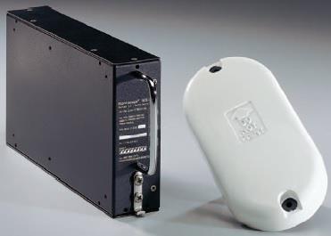
19 WX-500 Stormscope
20 Stormscope Overview Detects electrical discharges from thunderstorms within 200 nm of the aircraft Antenna detects intra-cloud, inter-cloud and cloud-toground discharges from thunderstorms in all phases of development Works in the air or on the ground Advantages Can detect thunderstorms in all states of development; weather radar will only detect storms when there is precipitation Not subject to attenuation can see behind the storm Disadvantages Calculating the distance is not an exact science: is a strong signal from a weak flash nearby, or an intense flash far away?

21 Display Modes Strike Mode Displays individual strikes in their calculated location Strikes will often show up in a radial pattern from the aircraft Cell Mode Algorithmic depiction of the location of individual cells Can be used to correlate the location of storm cells
22 Interpreting the Data Use strike mode when storms may be developing for more immediate detection of strikes Look for clusters of strikes to estimate the location of storm cells to avoid Atmospheric instability associated with cumulus clouds, or developing or dissipating storms might cause randomly scattered discharge points Use cell mode when there are developing storms for better estimation of actual storm cell locations Monitor the strike data as you go, and look for trends in the location and frequency of the strike points Be sure to clear the screen when heading changes are made Some installations will automatically couple with the aircraft heading
23 Final word on strike detection DO NOT USE FOR STORM PENETRATION PURPOSES! Strike detection is best used for strategic AVOIDANCE of storms Unlike data link weather, stormscope data is real-time Despite the impreciseness of the data, it is still useful for avoiding storms There is a strong correlation between electrical discharge and convective wind shear
24 Break Time!
25 Carburetor Probes

 when carb icing conditions")
26 Carb Temp Gauge Displays the temperature inside the carburetor venturi Keep the temperature either below -15C (5F) or above 5C (41F) when carb icing conditions exist


27 Carb Ice Detector Probe consists of a light emitter and a light sensor. When carb ice forms, it develops on the probe tip, reducing the light received by the sensor and activating the annunciator. Calibrating the sensor 1. Rotate the sensitivity knob fully counterclockwise so the carb ice light is on 2. Rotate the sensitivity knob clockwise until the carb ice light just goes out

28 General Autopilot Tips How to make the autopilot work for you
29 Autopilot Safety Know all of the ways to disconnect the autopilot Yoke-mounted disconnect switch (if installed) Autopilot master switch OFF Pull the autopilot circuit breaker Disabling runaway pitch trim Manually engage the electric pitch trim Pull the electric pitch trim circuit breaker Disconnect the entire autopilot (see above) Always be prepared for an out-of-trim condition when disengaging the autopilot Especially if automatic pitch trim is not enabled Always be ahead of the autopilot, and ready to hand-fly if necessary Practice in VFR conditions, or with a safety pilot who is fully proficient in its operation
30 Autopilot Tips Basic heading (HDG) mode is your friend If in doubt, control the autopilot with the heading bug Do not use the autopilot in moderate to severe turbulence, or while in icing conditions* Initiate course interception within 45º of desired course Greater intercept angles will likely result in course overshoot Make heading adjustments in 90º or less increments to ensure a turn in the desired direction Only use coupled approaches (LOC+GS capture) if you are fully proficient in the autopilot s operations * Never intentionally fly in icing conditions in a non-fiki approved aircraft!
31 Autopilot Tips (Cont.) Consider that single-pilot charter operations require an operational autopilot for IFR dispatching Learn the capabilities of the autopilot installed, and practice to proficiency When in doubt, disconnect! Don t let the autopilot do something you weren t expecting. If it does, either disconnect it, or revert back to basic heading hold. Whenever there is a course or altitude change coming up, monitor the autopilot to ensure it does what you expect After initially engaging the autopilot, monitor the aircraft for a few seconds to ensure the autopilot is working When using V/S hold, keep your hand near the autopilot as you near your level off altitude, so as not to bust the altitude
32 Automation Levels Use the concept of automation levels 1. Autopilot does all of the work, including intercepting and tracking the localizer and glideslope Example) Stec 55X in GPSS mode on an LPV approach 2. Simple heading and/or altitude hold autopilot doesn t change heading/altitude unless the pilot directly commands it 3. (If applicable) Hand-flying the flight director (autopilot off) 4. All automation off The pilot can move up and down the different levels as the need arises Example) Disengaging all automation to avoid a midair (L4), then reengaging the autopilot for level flight and manual course interception (L3/L2), and finally reengaging GPSS mode to reestablish the assigned course and altitude (L1).
33 Avoiding the WIDN Syndrome WIDN: What s it doing now? 1. Study and understand how all of the autopilot modes that you intend to use are designed and function 2. Be ready for the autopilot to do something different than you expect 3. Move up and down the automation levels as necessary to resolve a WIDN situation In resolving un-commanded pitch changes, most pilots (correct) initial reaction is to disconnect the autopilot and figure out why it did that later. However, the first reaction to an un-commanded roll is often to try and troubleshoot what it s doing, rather than the correct action which is to disconnect the autopilot and THEN troubleshoot.
34 Piper AutoControl IIIB Attitude-based roll computer
 navigation tracking Localizer approaches Back-course approaches 9-15 pounds of force to override the")
35 Overview Attitude-based autopilot Receives input from the AI Unavailable for use if there is a vacuum failure or AI instrument failure Provides the following modes Roll mode Essentially a wing-leveler with commandable turns Heading hold En-route navigation tracking Terminal (approach) navigation tracking Localizer approaches Back-course approaches 9-15 pounds of force to override the servos On/off switch Roll command Heading mode Heading switch En-route nav tracking Terminal nav tracking LOC tracking LOC BC tracking

36 Heading hold Roll Control 1. Select A/P ON and HDG OFF 2. The roll knob will bank the aircraft left or right, up to a 30-degree bank HDG (Heading) Mode 1. Align the DG to the magnetic compass 2. Set the desired heading to hold with the heading bug 3. Rotate the mode selector switch to HDG 4. Select A/P ON and HDG ON
37 Nav tracking Two different VOR/GPS modes NAV mode: Used for en-route navigation (damps out shortterm deviations) OMNI mode: Used for terminal-area (VOR/RNAV) approaches Navigation source is determined by the CDI GPS or VOR 1. Rotate the mode selector switch to NAV or OMNI 2. Tune in a VOR station (or set the nav source to GPS) and set the OBS to the desired course 3. Set the heading bug to the desired course 4. Select A/P ON and HDG ON
38 Approaches Two different localizer modes Standard LOC Localizer back-course No vertical coupling is available must hand-fly the glideslope However, this is still much easier than having to hand-fly both lateral and vertical paths 1. Rotate the mode selector switch to LOC NORM or LOC REV 2. Tune in the localizer and set the OBS to the localizer course 3. Set the heading bug to the localizer course 4. Select A/P ON and HDG ON
39 Stec 55/55X Rate-based 2-axis autopilot
40 Overview Rate-based autopilot Derives attitude information from the turn coordinator GPSS mode operational even with a complete vacuum failure Two-axis autopilot controls pitch and roll GPSS mode all course guidance derived from the GPS, including turn initiation Available modes Heading hold Nav (VOR/GPS) tracking Pilot-selectable course intercept Approach mode Including back-courses Altitude hold Vertical speed hold Climb/descend to selected altitude With installed ST360


")
41 Buttonology Stec 55/55X HDG + NAV Pilot Selectable Course Intercept REV Reverse Sensing Mode ALT + VS Climb/Descend to Selected Altitude (ST-360) VS Selector Knob HDG Heading Hold NAV VOR/GPS Course Tracking APR Approach Mode ALT Altitude Hold VS Vertical Speed Hold One of the lateral modes (HDG, NAV, APR/REV) must be engaged before any vertical mode (ALT, VS,GS) can be engaged
42 Heading & Nav Modes Heading (HDG) Mode Tracks the heading set with the heading bug En-route Navigation (NAV) Mode Tracks the selected OBS course The heading bug must also be set to the course heading NAV GPSS Mode Activated by pressing NAV twice Same as NAV mode, but all course guidance is derived from the GPS, including turn lead-ins and holding patterns Pilot-selectable Course Intercept (HDG+NAV) Same as NAV mode, but the heading bug is used to set the initial intercept course Need to reset the heading bug once the course is captured Approach (APR) Mode Same as NAV mode, but with increased sensitivity Back-course (REV) Mode Same as APR mode, but for tracking the localizer backcourse inbound
43 Altitude Modes Altitude Hold (ALT) Holds the current pressure altitude when the mode is engaged Altitude adjustments in 20 foot increments made with VS selector knob (CW+, CCW-) Vertical Speed Hold (VS) Hold a set vertical speed If aircraft is level, the V/S should be set with the VS selector knob If the aircraft is in a climb or descent, engagement will hold the current V/S Adjustments in 100 fpm increments made with VS selector knob (CW+, CCW-) Automatic climb/descent* Pitch trim Manual pitch trim Unit will annunciate TRIM ^ or TRIM v as required An audible annunciation will continue for 4 seconds The appropriate TRIM indication will remain lit until trim is met Automatic pitch trim Unit will auto-trim and annunciate TRIM ^ or TRIM v while trimming TRIM will flash if the trim is run for more than 7 seconds Auto trim will be disabled any time a fault is detected Using the electric pitch trim while ALT or VS modes are selected will disconnect the autopilot * Details on the following slide


44 Buttonology ST-360 Data Entry Button Barometric Entry Button Input Selector Knob Altitude Read Out / Selector Altitude Alerter V/S Selector Manual Mode Button* DH Alerter * Disconnects the ST-360 from the 55/55X
45 ST-360 Altitude Selector/Alerter Setting the barometric pressure 1. Verify ENT is displayed and BARO is flashing If not, press DTA followed by BAR 2. Set the baro pressure Pull the knob to set the tenths, push to set the tens 3. Press DTA to accept the set pressure Setting the level-off altitude 1. Press DTA until ENT and ALT are displayed, and SEL is flashing 2. Set the desired level-off altitude Pull the knob to set in 100s, push to set in 1000s 3. Press DTA to accept the altitude Enabling automatic climb/descent mode Press ALT+VS on the 55/55X head unit
46 ST-360 Altitude Selector/Alerter (Cont) Setting the decision height 1. Press DTA to annunciate ENT 2. Press DH The DH annunciation will flash 3. Set the decision altitude Set to the nearest 100 rounded up 4. Press DTA to activate An audible alert will sound at 50 above and 50 below the set DH Setting the altitude alterter 1. Set the altitude as described previously 2. Press ALR to arm the alerter function An audible alert will sound at 1000 and 300 from the selected altitude Following altitude capture, alerts will be generated when altitude is off by 300
47 Glideslope Intercept & Tracking Conditions to arm automatically NAV flag out of view GS flag out of view Autopilot must be in NAV+APR+ALT mode Aircraft must be within 50% of CDI needle deflection of LOC centerline 60% or more below the GDI needle deflection of GS path Manual GS capture still possible while within 20% or less above GS path

48 Glideslope Intercept & Tracking Mode progression 1. NAV+APR + ALT Approach mode armed 2. NAV+APR + ALT+GS Glideslope mode armed 3. NAV+APR + GS Glideslope captured Manually arming GS capture 1. Press ALT once if in ALT mode twice if in VS mode


49 More Information Flying 20 Club Library GMA 340 Manual GTX 330 Manual FS-450 Fuel Scanner Manual WX-500 Stormscope Manual AutoControl IIIB Manual Stec 55/55X Manuals AOPA Safety Advisors Single-Pilot IFR FAA AIM Traffic Information Service Advanced Avionics Handbook (FAA-H ) Special thanks to Brad Freeman for some of the original course material Open Sky Aviation, LLC.
Table of Contents. Introduction 3. Pictorials of the 40 and 50 Systems 4. List of Applicable Acronyms 6
 Table of Contents Introduction 3 Pictorials of the 40 and 50 Systems 4 List of Applicable Acronyms 6 System 40 Modes of Operation 7 System 40 Functional Preflight Procedures 10 System 40 In Flight Procedures
FAA APPROVED AIRPLANE FLIGHT MANUAL SUPPLEMENT FOR. Trio Pro Pilot Autopilot
 Page 1 480 Ruddiman Drive TRIO AP Flight Manual Supplement North Muskegon, MI 49445 L-1006-01 Rev D FOR Trio Pro Pilot Autopilot ON Cessna 172, 175, 177, 180, 182, 185 and Piper PA28 Aircraft Document
Fokker 50 - Automatic Flight Control System
 GENERAL The Automatic Flight Control System (AFCS) controls the aircraft around the pitch, roll, and yaw axes. The system consists of: Two Flight Directors (FD). Autopilot (AP). Flight Augmentation System
For Microsoft FSX and FS FriendlyPanels. All right reserved
 FriendlyPanels Software (version 2.0) For Microsoft FSX and FS9 2007 FriendlyPanels. All right reserved FOURTEEN GAUGES FOR YOUR FSX and FS9 AIRCRAFT 1 1. Introduction. 2. Requirements 3. Installing the
AT01 AIRPLANE FLIGHT MANUAL
 Table of Contents Supplement AVE12 1. Section 1 General AVE12 3 2. Section 2 Operating Limitations AVE12 3 3. Section 3 Emergency Procedures AVE12 3 4. Section 4 Normal Procedures AVE12 4 5. Section 5
SD3-60 AIRCRAFT MAINTENANCE MANUAL
 AMM 24.0.0.0FLIGHT DIRECTOR SYSTEM - DESCRIPTION & OPERATION 1. Description A. General Refer to Figure 1. Identical, left and right, systems are installed (one for each pilot); each provides information
G1000TM. audio panel pilot s guide
 G1000TM audio panel pilot s guide Record of Revisions Revision Date of Revision Revision Page Range Description A 12/01/04 6A-1 6A-17 Initial release. Garmin G1000 Audio Panel Pilot s Guide 190-00378-02
GRT Autopilot User Guide. All GRT EFIS Systems
 All GRT EFIS Systems Revision A 22-May-2014 Copyright 2014 3133 Madison Ave. SE Wyoming, MI 49548 (616) 245-7700 www.grtavionics.com Revision Notes Revision Date Change Description A 22-May-2014 Complete
Garmin GMA 340 Audio System
 Cirrus Design Section 9 Pilot s Operating Handbook and FAA Approved Airplane Flight Manual Supplement for Garmin GMA 340 Audio System Includes Optional XM Radio System When the Garmin GMA 340 Audio Panel
AUTOMATIC FLIGHT CONTROL SYSTEM
 TRIDEN AUTOMATIC FLIGHT CONTROL SYSTEM PILOT S OPERATING HANDBOOK 68S1135 Rev B 02-05-03 FACTORY SERVICE CENTERS Century Flight Systems, Inc. has established Factory owned and operated Customer Service
HAZARD AVOIDANCE. Displaying traffic on the Navigation Map. Displaying traffic information (PFD Inset Map):
:") HAZARD AVOIDANCE Displaying traffic on the Navigation Map 1) Ensure that the TAS system is operating. With the Navigation Map displayed, select the MAP Softkey. 2) Select the TRAFFIC Softkey. Traffic is
HAZARD AVOIDANCE Displaying traffic on the Navigation Map 1) Ensure that the TAS system is operating. With the Navigation Map displayed, select the MAP Softkey. 2) Select the TRAFFIC Softkey. Traffic is
Instrument Flight Procedures - Glass Cockpits
 Instrument Flight Procedures - Glass Cockpits The concepts contained here are general in nature and can be used by all however, they are targeted toward glass cockpits and, more specifically, integrated
Operating Handbook. For. Gemini Autopilot
 Operating Handbook For Gemini Autopilot TRUTRAK FLIGHT SYSTEMS 1488 S. Old Missouri Road Springdale, AR 72764 Ph. 479-751-0250 Fax 479-751-3397 www.trutrakap.com Table of Contents 1. Revisions... 5 2.
Dash8 - Q400 - Autoflight
 12.3.1 Introduction The Automatic Flight Control System (AFCS), provides fail-safe operation of flight director guidance, autopilot, yaw damper and automatic pitch trim functions. 12.3.2 General The Automatic
G1000TM. audio panel pilot s guide
 G1000TM audio panel pilot s guide Record of Revisions Revision Date of Revision Revision Page Range Description A 08/20/04 6A-1 6A-18 Initial release. Garmin G1000 Audio Panel Pilot s Guide 190-00378-01
Dash8-200/300 - Automatic Flight AUTOMATIC FLIGHT CONTROLS AND INDICATORS. Page 1
 AUTOMATIC FLIGHT CONTROLS AND INDICATORS FLIGHT GUIDANCE MODE SELECTORS (alternate action) - Engages flight director modes of operation. - Flight director command bars display lateral and/or vertical guidance
SkyView. Autopilot In-Flight Tuning Guide. This product is not approved for installation in type certificated aircraft
 SkyView Autopilot In-Flight Tuning Guide This product is not approved for installation in type certificated aircraft Document 102064-000, Revision B For use with firmware version 10.0 March, 2014 Copyright
ENSTROM 480/480B OPERATOR S MANUAL AND FAA APPROVED ROTORCRAFT FLIGHT MANUAL SUPPLEMENT GARMIN GNS 430W/530W NAVIGATION SYSTEM
 ENSTROM 480/480B OPERATOR S MANUAL AND FAA APPROVED ROTORCRAFT FLIGHT MANUAL SUPPLEMENT GARMIN GNS 430W/530W NAVIGATION SYSTEM * * * * * REPORT NO. 28-AC-055 HELICOPTER SERIAL NO. HELICOPTER REGISTRATION
G1000 Integrated Flight Deck
 G1000 Integrated Deck Cockpit Reference Guide for the Beechcraft 200/B200 Series System Software 0985.00 or later Transponder/Audio Panel Automatic Control System GPS Navigation Planning Procedures Features
Page Chg
 Page Chg Cover...0 Page #...2 TOC-1...2 TOC-2..2 1-1 2 1-2.2 1-3.2 1-4...2 1-5...2 1-6. 2 1-7. 2 1-8. 2 1-9. 2 1-10...2 1-11..2 1-12..2 1-13..2 1-14..2 1-15..2 1-16..2 1-17..2 1-18...2 2-1.0 2-2.0 2-3.2
Digiflight II SERIES AUTOPILOTS
 Operating Handbook For Digiflight II SERIES AUTOPILOTS TRUTRAK FLIGHT SYSTEMS 1500 S. Old Missouri Road Springdale, AR 72764 Ph. 479-751-0250 Fax 479-751-3397 Toll Free: 866-TRUTRAK 866-(878-8725) www.trutrakap.com
Operating Handbook For FD PILOT SERIES AUTOPILOTS
 Operating Handbook For FD PILOT SERIES AUTOPILOTS TRUTRAK FLIGHT SYSTEMS 1500 S. Old Missouri Road Springdale, AR 72764 Ph. 479-751-0250 Fax 479-751-3397 Toll Free: 866-TRUTRAK 866-(878-8725) www.trutrakap.com
KAP 140 Two Axis with Altitude Preselect Operation
 Two Axis/Altitude reselect Operations K 0 Two Axis with Altitude reselect Operation The K 0 is a digital, panel-mounted autopilot system for light aircraft. 7 8 K 0 D AV V AT D Two-axis w/altitude reelect
2001 by UPS Aviation Technologies, Inc. All rights reserved. Printed in the U.S.A.
 No part of this document may be reproduced in any form or by any means without the express written consent of UPS Aviation Technologies, Inc. II Morrow and Apollo are trademarks of UPS Aviation Technologies,
Operating Handbook. For. Gemini Autopilot
 Operating Handbook For Gemini Autopilot TRUTRAK FLIGHT SYSTEMS 1488 S. Old Missouri Road Springdale, AR 72764 Ph. 479-751-0250 Fax 479-751-3397 www.trutrakap.com Table of Contents 1. Revisions... 5 2.
9.1 General. f-i TABLE OF CONTENTS SECTION 9 SUPPLEMENTS REPORT: VB-880
 TABLE OF CONTENTS Paragraph/ Supplement No. 9.1 General Page No. 9-1 I z J 4 5 6 AutoFIite II Autopilot Installation 9-3 AutoControl IIIB Autopilot Installation 9-5 Piper Electric Pitch Trim 9-9 Air Conditioning
Digiflight II SERIES AUTOPILOTS
 Operating Handbook For Digiflight II SERIES AUTOPILOTS TRUTRAK FLIGHT SYSTEMS 1500 S. Old Missouri Road Springdale, AR 72764 Ph. 479-751-0250 Fax 479-751-3397 Toll Free: 866-TRUTRAK 866-(878-8725) www.trutrakap.com
NAVIGATION AND PITOT-STATIC SYSTEMS
 NAVIGATION AND PITOT-STATIC SYSTEMS. GENERAL This chapter describes the navigation systems, units, and components which provide airplane navigational information. Included are pitot-static, gyros, compass,
P/N 135A FAA Approved: 7/26/2005 Section 9 Initial Release Page 1 of 10
 FAA APPROVED AIRPLANE FLIGHT MANUAL SUPPLEMENT FOR GARMIN GNS 430 - VHF COMM/NAV/GPS Serial No: Registration No: When installing the Garmin GNS 430 - VHF COMM/NAV/GPS in the Liberty Aerospace XL2, this
9800 Martel Road Lenoir City, TN PMA6000B
 9800 Martel Road Lenoir City, TN 37772 www.ps-engineering.com PMA6000B Audio Control Panel Marker Beacon and Intercom Pilot s Guide and Operation Manual FAA-TSO C50c, C35d EASA ETSO C50c, 2C35d US Patent
RADIO SYSTEM DESCRIPTION The radio system consists of the following equipment:
 COMMUNICATION SYSTEM RADIO SYSTEM DESCRIPTION The radio system consists of the following equipment: Radio tuning function located in MFD s Dual CDU s (for tuning - shared with FMS) Two VHF communication
KMD 550/850. Traffic Avoidance Function (TCAS/TAS/TIS) Pilot s Guide Addendum. Multi-Function Display. For Software Version 01/13 or later
 Pilot s Guide Addendum. Multi-Function Display. For Software Version 01/13 or later") N B KMD 550/850 Multi-Function Display Traffic Avoidance Function (TCAS/TAS/TIS) Pilot s Guide Addendum For Software Version 01/13 or later Revision 3 Jun/2004 006-18238-0000 The information contained
N B KMD 550/850 Multi-Function Display Traffic Avoidance Function (TCAS/TAS/TIS) Pilot s Guide Addendum For Software Version 01/13 or later Revision 3 Jun/2004 006-18238-0000 The information contained
Page Chg
 Page Chg Cover...0 Page #...4 TOC-1...3 TOC-2..3 1-1 2 1-2.3 1-3.3 1-4...3 1-5...3 1-6. 3 1-7. 3 1-8. 4 1-9. 4 1-10...3 1-11..4 1-12..4 1-13..3 1-14..3 1-15..3 1-16..3 1-17..3 1-18...3 1-19..3 2-1.0 2-2.0
ENSTROM 480B OPERATOR S MANUAL AND FAA APPROVED ROTORCRAFT FLIGHT MANUAL SUPPLEMENT GARMIN GTN 650 NAVIGATION SYSTEM
 ENSTROM 480B OPERATOR S MANUAL AND FAA APPROVED ROTORCRAFT FLIGHT MANUAL SUPPLEMENT GARMIN GTN 650 NAVIGATION SYSTEM * * * * * REPORT NO. 28-AC-064 HELICOPTER SERIAL NO. HELICOPTER REGISTRATION NO. * *
2000 by UPS Aviation Technologies, Inc. All rights reserved. Printed in the U.S.A.
 No part of this document may be reproduced in any form or by any means without the express written consent of UPS Aviation Technologies, Inc. UPS Aviation Technologies, Inc., II Morrow, and Apollo are
Page Chg
 Page Chg Cover...0 Page #...1 TOC-1...1 TOC-2...1 1-1.1 1-2.0 1-3.1 1-4...1 1-5...1 1-6. 1 1-7. 1 1-8. 1 1-9. 1 1-10...1 1-11..1 1-12..1 1-13..2 1-14..1 1-15..1 1-16..1 1-17..1 1-18..1 2-1.0 2-2.0 Page
Page Chg
 Page Chg Cover...0 Page #...1 TOC-1...1 TOC-2..1 1-1.1 1-2.1 1-3.1 1-4...0 1-5...1 1-6. 1 1-7. 1 1-8. 1 1-9. 1 1-10...1 1-11..1 1-12..1 1-13..1 1-14..1 2-1.0 2-2.0 2-3.1 Page Chg 2-4.0 3-1.0 3-2.0 3-3.0
Integrated Cockpit Display System ICDS 1000 Pilot Operation Handbook
 Integrated Cockpit Display System ICDS 1000 Pilot Operation Handbook ICDS1000 Pilot Operating Handbook Revision 1.3 572-0540 page 1 Table Of Contents Electronic Attitude Direction Indicator (EADI)... 8
KMA 24 and KMA 24H Bendix/King Audio Control Systems
 KMA 24 and KMA 24H Bendix/King Audio Systems Compact TSO d consoles make audio control push button simple Push button simplicity puts complete, flexible audio control right at your fingertips with Bendix/King
G1000 Integrated Flight Deck. Cockpit Reference Guide for the Mooney M20M, M20R, & M20TN
 G1000 Integrated Deck Cockpit Reference Guide for the Mooney M20M, M20R, & M20TN FLIGHT INSTRUMENTS EIS NAV/COM/TRANSPONDER/AUDIO PANEL AUTOMATIC FLIGHT CONTROL SYSTEM GPS NAVIGATION FLIGHT PLANNING PROCEDURES
G1000 Integrated Flight Deck
 G1000 Integrated Deck Cockpit Reference Guide for the Piper PA-46 Mirage/Matrix System Software 0720.10 or later Instruments EICAS Transponder/Audio Panel Automatic Control System GPS Navigation Planning
Apollo Model SL10 Series Audio Selector Panel User s Guide
 Apollo Model SL10 Series Audio Selector Panel December 2001 560-0973-00a No part of this document may be reproduced in any form or by any means without the express written consent of UPS Aviation Technologies,
BEECHCRAFT SUPER KING AIR B200 Model: 1998 Crew: 2 pilots Passengers: 7
 BEECHCRAFT SUPER KING AIR B200 Model: 1998 Crew: 2 pilots Passengers: 7 AIRFRAME: 2996:09 Hours TSN Landings: 2314 ENGINES: Pratt & Whitney PW545A Left Engine: 2996:09 Hours TSN 2314 Cycles SN Right Engine:
G1000 Integrated Flight Deck. Cockpit Reference Guide for the DA42
 G1000 Integrated Deck Cockpit Reference Guide for the DA42 Instruments ENGINE INDICATION SYSTEM Transponder/Audio Panel Automatic Control System GPS Navigation Planning Procedures Annunciations & Alerts
GMA 240 Pilot s Guide
 GMA 240 Pilot s Guide Copyright 2008 Garmin Ltd. or its subsidiaries. All rights reserved. This manual reflects the operation of GMA 240 units with mod level 0 or later. Some differences in operation may
G1000 Integrated Flight Deck
 G1000 Integrated Deck Cockpit Reference Guide for the Cessna Caravan System Software 0767.02 or later Instruments EIS Transponder/Audio Panel Automatic Control System GPS Navigation Planning Procedures
G1000 Integrated Flight Deck
 G1000 Integrated Deck Cockpit Reference Guide System Software 0719.03 or later Instruments ENGINE & AIRFRAME SYSTEMS Transponder/Audio Panel Automatic Control System GPS Navigation Planning Procedures
G1000 Integrated Flight Deck. Cockpit Reference Guide for the Cessna Caravan
 G1000 Integrated Deck Cockpit Reference Guide for the Cessna Caravan Instruments EIS Transponder/Audio Panel Automatic Control System GPS Navigation Planning Procedures Annunciations & Alerts INDEx Copyright
Pilot s Operating Handbook Supplement AS-21
 SECTION 9 Pilot s Operating Handbook Supplement Mode S Transponder GARMIN GTX 335 / GTX 345 This supplement is applicable and must be inserted into Section 9 of the POH when a GARMIN GTX 335 or GTX 345
Pilot s Guide KI 825. Bendix/King Safety Display System Electronic Horizontal Situation Indicator For Units Having -2, -3 and -4 Softwa re
 N Pilot s Guide KI 825 Bendix/King Safety Display System Electronic Horizontal Situation Indicator For Units Having -2, -3 and -4 Softwa re W A R N I N G The enclosed technical data is eligible for export
MGL Avionics. Odyssey/Voyager G2 and iefis
 MGL Avionics Odyssey/Voyager G2 and iefis Navigation This document applies to G2 version 1.1.0.1 or later, iefis 1.0.0.3 or later. Note: This document is based on the G2. The iefis system provides identical
This page is intentionally blank. GARMIN G1000 SYNTHETIC VISION AND PATHWAYS OPTION Rev 1 Page 2 of 27
 This page is intentionally blank. 190-00492-15 Rev 1 Page 2 of 27 Revision Number Page Number(s) LOG OF REVISIONS Description FAA Approved Date of Approval 1 All Initial Release See Page 1 See Page 1 190-00492-15
Sigma-Tek 1U Radio Control Panel Operator s Manual
 Sigma-Tek 1U619-001 Radio Control Panel Operator s Manual 86M069 TABLE OF CONTENTS 1.0 GENERAL...1 1.1 DESCRIPTION...1 1.2 THEORY OF OPERATION...2 2.0 VHF COMMUNICATION MODULES...7 2.1 OPERATING PROCEDURE...8
11 Traffic-alert and Collision Avoidance System (TCAS)
") 11 Traffic-alert and Collision Avoidance System (TCAS) INSTRUMENTATION 11.1 Introduction In the early nineties the American FAA stated that civil aircraft flying in US airspace were equipped with a Traffic-alert
11 Traffic-alert and Collision Avoidance System (TCAS) INSTRUMENTATION 11.1 Introduction In the early nineties the American FAA stated that civil aircraft flying in US airspace were equipped with a Traffic-alert
Pro Pilot Operation and Installation Manual Trio Avionics Corporation
 Pro Pilot Operation and Installation Manual Trio Avionics Corporation Version 3.8 Notice: This manual uses illustrations that generally show the Pro Pilot model that mounts in a standard 3-1/8 round cutout
SECTION 2-19 AUTOPILOT
 AIRPLANE SECTION 2-19 Block General...2-19-05...01 Automatic Flight Control System...2-19-05...02 Flight Guidance System...2-19-05...04 Flight Director...2-19-05...04 Autopilot...2-19-05...04 Flight Director
GMA 347. audio panel pilot s guide
 GMA 347 audio panel pilot s guide WARRANTY LIMITED WARRANTY This Garmin product is warranted to be free from defects in materials or workmanship for two years from the date of purchase. Within this period,
STC FLIGHT FUNCTIONAL TEST
 GDC31 Roll Steering Converter 1049-2080-02 REV A 2004, DAC International All Rights Reserved. 6702 McNeil Drive Austin, Texas 78729 (512) 331-5323 Phone (512) 331-4516 Fax Page 1 of 14 Record of Revisions
GNS 430 Basic Usage. VFR GPS Usage
 GNS 430 Basic Usage VFR GPS Usage Disclaimer This briefing is to designed to give an introductory overview so that as you read the GNS 430 Pilot s Guide and Reference you will have a basic understanding
How to Intercept a Radial Outbound
 How to Intercept a Radial Outbound by Greg Whiley Another practical publication from Aussie Star Flight Simulation How to intercepting a radial outbound 1 Greg Whiley Aussie Star Flight Simulation How
G1000 Integrated Flight Deck. Cockpit Reference Guide for the DA42
 G1000 Integrated Deck Cockpit Reference Guide for the DA42 FLIGHT INSTRUMENTS ENGINE INDICATION SYSTEM NAV/COM/TRANSPONDER/AUDIO PANEL AUTOMATIC FLIGHT CONTROL SYSTEM GPS NAVIGATION FLIGHT PLANNING PROCEDURES
G1000 Integrated Flight Deck. Cockpit Reference Guide for the Beechcraft A36/G36
 G1000 Integrated Deck Cockpit Reference Guide for the Beechcraft A36/G36 Instruments ENGINE INDICATION SYSTEM Transponder/Audio Panel Automatic Control System GPS Navigation Planning Procedures Annunciations
G1000 Integrated Flight Deck. Cockpit Reference Guide for the Cessna Citation Mustang
 G1000 Integrated Flight Deck Cockpit Reference Guide for the Cessna Citation Mustang FLIGHT INSTRUMENTS NAV/COM/TRANSPONDER/AUDIO PANEL AUTOMATIC FLIGHT CONTROL SYSTEM GPS NAVIGATION FLIGHT PLANNING PROCEDURES
G1000 Integrated Flight Deck. Cockpit Reference Guide for the Beechcraft 58/G58
 G1000 Integrated Deck Cockpit Reference Guide for the Beechcraft 58/G58 FLIGHT INSTRUMENTS ENGINE INDICATION SYSTEM NAV/COM/TRANSPONDER/AUDIO PANEL AUTOMATIC FLIGHT CONTROL SYSTEM GPS NAVIGATION FLIGHT
G1000 Integrated Flight Deck
 G1000 Integrated Deck Cockpit Reference Guide for the Cessna 350/400 System Software 0534.11 or later Instruments ENGINE INDICATION SYSTEM Transponder/Audio Panel Automatic Control System GPS Navigation
EMBRAER 135/145 Autopilot
 EMBRAER 135/145 Autopilot GENERAL The Primus 1000 (P-1000) Automatic Flight Control System (AFCS) is a fully integrated, fail passive three-axis flight control system which incorporates lateral and vertical
Introduction. Traffic Symbology. System Description SECTION 12 ADDITIONAL FEATURES
 12.2 Traffic Advisory Systems (TAS) Introduction All information in this section pertains to the display and control of the Garmin GNS 430/GTS 800 interface. NOTE: This section assumes the user has experience
Radio Navigation Stack. User Manual
 Radio Navigation Stack User Manual Table Of Contents Introduction Installation 2D Panel Configuration 3D (Virtual Cockpit) Use KMA 30 Audio Panel KX 165A Navigation/Communication Radio KX 165 Navigation/Communication
Pro Pilot Operation Manual Trio Avionics Corporation
 Pro Pilot Operation Manual Trio Avionics Corporation Manual Part Number 13200000 Notice: This manual uses illustrations that generally show the Pro Pilot model that mounts in a standard 3-1/8 round cutout
FOUND FBA-2C1/2C2 BUSH HAWK EQUIPPED WITH SINGLE GARMIN GNS-430 # 1 VHF-AM COMM / VOR-ILS / GPS RECEIVER
 FOUND SUPPLEMENT M400-S11 Transport Canada Approved Flight Manual Supplement For FOUND BUSH HAWK EQUIPPED WITH SINGLE # 1 VHF-AM COMM / VOR-ILS / GPS RECEIVER Section 1 General is Unapproved and provided
Post-Installation Checkout All GRT EFIS Models
 GRT Autopilot Post-Installation Checkout All GRT EFIS Models April 2011 Grand Rapids Technologies, Inc. 3133 Madison Avenue SE Wyoming MI 49548 616-245-7700 www.grtavionics.com Intentionally Left Blank
SL30 TM. pilot s guide. color gps/waas/nav/comm. pilot s guide
 SL30 TM GNS nav com480 TM pilot s guide color gps/waas/nav/comm pilot s guide 2010 Garmin Ltd. or its subsidiaries Garmin International, Inc. Garmin AT 1200 East 151 st Street, Olathe, Kansas 66062, U.S.A.
PMA8000E Audio Selector Panel Marker Beacon Receiver Stereo Intercom System with Bluetooth Connectivity For Dual Audio Panel Installations
 9800 Martel Road Lenoir City, TN 37772 www.ps-engineering.com PMA8000E Audio Selector Panel Marker Beacon Receiver Stereo Intercom System with Bluetooth Connectivity For Dual Audio Panel Installations
400W / 500W Series Display Interfaces
 400W / 500W Series Display Interfaces Pilot s Guide Addendum L-3 STORMSCOPE WX-500 Weather Mapping Sensor L-3 SKYWATCH Traffic Advisory System (Model SKY497) L-3 SKYWATCH HP Traffic Advisory System (Model
AMS44 and AMS44T Dual Channel Audio Controllers OPERATOR S MANUAL
 AMS44 and AMS44T Dual Channel Audio Controllers OPERATOR S MANUAL REV 1.11 December 4, 2002 Northern Airborne Technology Ltd. 1925 Kirschner Road Kelowna, BC, Canada. V1Y 4N7 Telephone (250) 763-2232 Facsimile
GMA 342 pilot s guide
 GMA 342 pilot s guide Copyright 2011, 2016 Garmin Ltd. or its subsidiaries. All rights reserved. This manual reflects the operation of GMA 342 units. Some differences in operation may be observed when
Basic GPS Operation. by Greg Whiley. Another practical publication from Aussie Star Flight Simulation
 Basic GPS Operation by Greg Whiley Another practical publication from Aussie Star Flight Simulation INTENTIONALLY LEFT BLANK Aussie Star Flight Simulation 2 Basic GPS Operations Statement of copyright
Cockpit Voice Recorder Intelligibility Analysis Flight Test Procedures
 Registration: Serial #: Model: Date: Important Note To Flight Crew The procedures detailed in this report are intended to demonstrate that the CVR records the required information. Failure to follow each
Bendix/King Silver Crown Plus Avionics Systems Pilot s Guide
 Audio Panel Systems Communication Transceivers Nav/Comm Systems Navigation Receiver DME Systems ADF System Transponders Bendix/King Silver Crown Plus Avionics Systems Pilot s Guide N N The information
JA Audio Controller
 JA95-001 Audio Controller Rev. A Page 1 Copyright 2013 Jupiter Avionics Corp. All rights reserved Jupiter Avionics Corporation (JAC) permits a single copy of this manual to be printed or downloaded for
canadair chauenqer 4 - CONTENTS Page 1 Oct 03/83 SECTION 4 AUTOMATIC FLIGHT CONTROL SYSTEM TABLE OF CONTENTS GENERAL 1 FLIGHT DIRECTOR SYSTEM 1
 canadair chauenqer AUTOMATIC FLIGHT CONTROL SYSTEM TABLE OF CONTENTS Subject ZiSi GENERAL 1 FLIGHT DIRECTOR SYSTEM 1 AIR DATA SYSTEM 2 AUTOPILOT SYSTEM '- STABILITY AUGMENTATION SYSTEM? Yaw Damping Mach
Installation Guide For Vizion PMA Autopilot
 Installation Guide For Vizion PMA Autopilot RESTRICTION ON USE, DUPLICATION, OR DISCLOSURE OF PROPRIETARY INFORMATION THIS DOCUMENT CONTAINS PROPRIETARY INFORMATION OF TRUTRAK FLIGHT SYSTEMS, INC. AND
NAVIGATION INSTRUMENTS - BASICS
 NAVIGATION INSTRUMENTS - BASICS 1. Introduction Several radio-navigation instruments equip the different airplanes available in our flight simulators software. The type of instrument that can be found
SUPPLEMENT REVISION CESSNA MODEL 182T
 SUPPLEMENT REVISION CESSNA MODEL 182T NAV III AVIONICS OPTION - Serials 18281228 and 18281318 thru 18281868 and 18281870 thru 18281875 PILOTS OPERATING HANDBOOK AND AIRPLANE FLIGHT MANUAL REVISION 1 1
400/500 Series Display Interfaces
 400/500 Series Display Interfaces Pilot s Guide Addendum Goodrich STORMSCOPE WX-500 Series II Weather Mapping Sensor Goodrich SKYWATCH Traffic Advisory System (Model SKY497) Goodrich SKYWATCH HP Traffic
AP OLLO S L15M Audio Control Panel and Marker Beacon Receiver
 SkyRentals INFO FOR VH-VMA Insert to SECTION 7 MODEL 182Q (1977) Audio Control Panel & Marker Receiver AP OLLO S L15M Audio Control Panel and Marker Beacon Receiver Audio Panel & Marker components 1A Apollo
ADF-650D Automatic Direction Finder System Pilot s Operating Handbook
 ADF-650D Automatic Direction Finder System Pilot s Operating Handbook V O L 1.1 2 0 MHz ADF List of Effective Pages * Asterisk indicates pages changed, added, or deleted by revision. Record of Revisions
Head-Up Guidance System. HGS Pilot Guide for the Bombardier CRJ 700
 Head-Up Guidance System HGS Pilot Guide for the Bombardier CRJ 700 Registration Notice HGS is a registered trademark of Rockwell Collins Flight Dynamics Proprietary Notice The information contained in
AP OL LO SL 60 VHF Communications Transceiver and GNSS (GPS) Navigation Receiver
 Navigation Receiver") SkyRentals INFO FOR VH-VMA Insert to SECTION 9 MODEL 182Q (1977) VHF Com1 & GNSS Nav Receiver AP OL LO SL 60 VHF Communications Transceiver and GNSS (GPS) Navigation Receiver VHF Com1 & GNSS Nav components
SkyRentals INFO FOR VH-VMA Insert to SECTION 9 MODEL 182Q (1977) VHF Com1 & GNSS Nav Receiver AP OL LO SL 60 VHF Communications Transceiver and GNSS (GPS) Navigation Receiver VHF Com1 & GNSS Nav components
JA Audio Controller Six Transceiver
 JA95-002 Audio Controller Six Transceiver Rev. A Page 1 JA95-002 Audio Controller Six Transceiver Copyright 2014 Jupiter Avionics Corp. All rights reserved Jupiter Avionics Corporation (JAC) permits a
G1000TM. Cockpit Reference Guide for the Beechcraft A36/G36
 G1000TM Cockpit Reference Guide for the Beechcraft A36/G36 Copyright 2005 Garmin Ltd. or its subsidiaries. All rights reserved. This manual reflects the operation of System Software version 0458.01 or
INSTALLATION MANUAL AND OPERATING INSTRUCTIONS
 INSTALLATION MANUAL AND OPERATING INSTRUCTIONS MD200-302/303/306/307 Series COURSE DEVIATION INDICATOR MID-CONTINENT INST. CO., INC MANUAL NUMBER 8017972 Revisions Rev. Date Description of Change ECO#
Cirrus SR20/SR22/SR22T. Integrated Avionics System Cockpit Reference Guide
 Cirrus SR20/SR22/SR22T Integrated Avionics System Cockpit Reference Guide Instruments EIS Transponder/Audio Panel Automatic Control System GPS Navigation Planning Procedures Annunciations & Alerts Appendix
KAP 140. Pilot s Guide. Bendix/King Autopilot System Rev. 2 May 02
 ilot s uide K 140 Bendix/King Autopilot ystem ev. 2 May 02 00-1804-0000 AI rior to export of this document, review for export license requirement is needed. COYIT OTIC Copyright 1998, 2002 oneywell International
NAVIGATION INTRUMENTATION ADF
 1. Introduction NAVIGATION INTRUMENTATION ADF The Automatic Direction Finding (ADF) equipment on-board of aircraft is used together with the Non Directional Beacon (NDB) transmitters installed on the ground.
JA Audio Controller Data Sheet
 TM JA95-001 Audio Controller Data Sheet Description The JA95-001 audio controller is a compact, lightweight unit that incorporates the latest technology, and is compatible with the current industry standard
NDB Approach Background
 NDB Approaches 1 NDB Approach Background One of the oldest and most disliked approaches Can use NDBs both on and off of the destination airport NDB approaches can be on the TO or FROM side of an NDB; some
CHAPTER NAVIGATION SYSTEMS
 18--00--1 NAVIGATION SYSTEMS Table of Contents REV 3, May 03/05 CHAPTER 18 --- NAVIGATION SYSTEMS Page TABLE OF CONTENTS 18-00 Table of Contents 18--00--1 INTRODUCTION 18-10 Introduction 18--10--1 FLIGHT
Pilot s Guide and Operation Manual
 9800 Martel Road Lenoir City, TN 37772 www.ps-engineering.com PMA8000-Series Audio Selector Panel Marker Beacon Receiver High-fidelity Stereo Intercom System Flying Never Sounded So Good! PS Engineering,
AUTOMATIC FLIGHT CONTROL SYSTEM TABLE OF CONTENTS CHAPTER 4
 TABLE OF CONTENTS CHAPTER 4 Page TABLE OF CONTENTS DESCRIPTION General Guidance Panel Autopilot System Autopilot Yaw Damper Autopilot Engage Autopilot Disengage PFD Annunciation Flight Director (FD) Flight