Star Microwave. Sygnus SHC Microwave Radio. Installation and Operation Manual. v. 1.0
|
|
|
- Georgia Logan
- 5 years ago
- Views:
Transcription

1 Star Microwave Sygnus SHC Microwave Radio Installation and Operation Manual v. 1.0
2 The information contained in this document is of commercial value, and is proprietary to Star Microwave. It is conveyed to the recipient solely for the purpose of evaluation. Reproduction of this document, disclosure of its contents or any other use of the information herein is strictly forbidden unless expressly authorized in writing by Star Microwave. Star Microwave Corp. Sygnus SHC Installation Guide Notices Radio Frequency Statement Sygnus SHC has been tested and found to comply with part 15 of the FCC rules and EN rules. These limits are designed to provide reasonable protection against harmful interference when the equipment is operated in a residential environment notwithstanding use in commercial, business and industrial environments. Operation is subject to the following two conditions: (1) This device may not cause harmful interference, and (2) This device must accept any interference received, including interference that may cause undesired operation. IMPORTANT! It is the responsibility of the installer to ensure that when using the outdoor antenna kits in the United States (or where FCC rules apply), only those antennas certified with the product are used. The use of any antenna other than those certified with the product is expressly forbidden in accordance to FCC rules CFR47 part IMPORTANT! Outdoor units and antennas should be installed ONLY by experienced installation professionals who are familiar with local building and safety codes and, wherever applicable, are licensed by the appropriate government regulatory authorities. Failure to do so may void the product warranty and may expose the end user or the service provider to legal and financial liabilities. Star Microwave and its resellers or distributors of this equipment are not liable for injury, damage or violation of regulations associated with the installation of outdoor units or antennas. R&TTE Declaration on Conformity Hereby, Star Microwave Ltd, declares that Sygnus SHC is in compliance with the essential requirements and other relevant provisions of Directive 1999/5/EC. The declaration of conformity may be consulted through Star Microwave Corp., Teradion Industrial Park, Misgav 20179, Israel. Compliance with European Union WEEE Directives In January 2003, the European Union adopted an important environmental directive - - the Directive on Waste Electrical and Electronic Equipment (WEEE). It represents an important milestone in providing a safer environment for future generations. The WEEE label and instructions for disposal are as follows: Star Microwave Corp. Sygnus SHC Installation Guide Instructions for Disposal of Waste Equipment by Users in the European Union This symbol on the product or its packaging indicates that this product must not be disposed of with other waste. Instead, it is your responsibility to dispose of your waste equipment by handing it over to a designated collection point for the recycling of waste electrical and electronic equipment. The separate collection and recycling of your waste equipment at the time of disposal Page 1 of 48
3 will help conserve natural resources and ensure that it is recycled in a manner that protects human health and the environment. For more information about where you can drop off your waste equipment for recycling, please contact Star Microwave. Warranty Star Microwave warrants that this product shall be free from defects in workmanship and materials for a period of one year from the date of original purchase. If the product should fail to operate correctly in normal use during the warranty period, Star Microwave will replace or repair it free of charge. No liability can be accepted for damage due to misuse or circumstances outside Star Microwave s control. Star Microwave will not be responsible for any loss, damage or injury arising directly or indirectly from the use of this product. Star Microwave s total liability under the terms of this warranty shall in all circumstances be limited to the replacement value of this product. If any difficulty is experienced in the installation or use of this product that you are unable to resolve, please contact Star Microwave. Star Microwave Corp. Sygnus SHC Installation Guide Page 2 of 48
4 Table of Contents 1. INTRODUCTION Applications Technical Overview Element Management System NMS Link Manager Standard Protocols INSTALLATION Packing List Additional Part List Required for Installation Installation Overview Testing before outdoor installation Quick Configuration Install the Link Manager program Sygnus SHC MU configuration MU Installation window Link configuration SU configuration Checking the setup Typical outdoor installation scheme: Installation process summary: Select the Best Location Mounting Antennas Alignment Sealing Cables Indoor Outlet Installation Grounding Consecutive AP Connection Synchronization LINK MANAGER General Activating the Link Manager Menu Commands 31 Page 3 of 48
5 Selecting Adapter Toolbar Commands Start Session (s) End session (E) Refresh Unit Parameters (!) Auto Reconnect ({}) Start Logger (EL) Stop Logger (DL) Clear Log (X) Log to File View Log Reset Text (RT) Reset Unit (RU) Installation Window Advanced Window Software Window Firmware Window RF Analyzer Tests TELNET Telnet Features Telnet Prompt Telnet Commands SYGNUS SHC TECHNICAL SPECIFICATIONS Radio Networking and Management Physical and Environmental TECHNICAL SPECIFICATIONS Radio Networking and Management Physical and Environmental APPENDIX A OUTDOOR CABLES SCHEME APPENDIX B RF CHANNEL LISTS FCC operating Band: 5725 MHz MHz APPENDIX C FCC APPROVED ANTENNAS 47 Page 4 of 48
6 Table of Figures Figure 1: Sygnus SHC PTP (blue) and PTMP (red)... 6 Figure 2: Sygnus SHC 2x2 dual polarization MIMO... 7 Figure 3: Automatic interference sensibility... 8 Figure 4: Multiple Sygnus SHC MUs on one tower... 9 Figure 5: Self-interference without time synchronization... 9 Figure 6: Time synchronization eliminates self-interference... 9 Figure 7: Consecutive AP principle Figure 8: Network Management System Figure 9: Link Manager Figure 10: Built in RF analyzer and throughput test tool Figure 11: WEB interface Figure 12: General System Components View Figure 13: Pre-test and setup network scheme Figure 14: General Installation Scheme Figure 15: MU link configuration window Figure 16: SU installation window Figure 17: Wall mounting Figure 18: Cable preparation for Outdoor Unit Figure 19: Cable assembly to Outdoor Unit Figure 20: Cable insertion to Outdoor Unit Figure 21: Cable connection to Outdoor Unit Figure 22: Indoor Unit with Power over Ethernet (PoE) Figure 23: Ground Connection to Outdoor Unit Figure 24: Link Manager - First Window Figure 25: Adapter selection window Figure 26: Discover window Figure 27: Direct login Figure 28: Installation window Figure 29: Advanced window Figure 30: Software window Figure 31: Firmware window Figure 32: RF Analyzer window Figure 33: Tests window Figure 34: Outdoor Cables Scheme Figure 35: Integrated / external antennas for Sygnus SHC Page 5 of 48
7 1. Introduction Thank you for purchasing Sygnus SHC point-to-point solution. Sygnus SHC is a carrier grade, the best of its class point-to-point and Point-to-multipoint broadband wireless bridge. Sygnus SHC is the next generation of radio technology with field proven features of Sygnus SHC. Sygnus SHC comprises of Reliability, High Capacity, Lowest Latency, RF Robustness, Rugged outdoor design, Flexibility and Simplicity to install and maintain Applications Point-to-Point (PTP): The basic subsystem is composed of a Master Unit (MU) and a Slave Unit (SU). Typical applications: IP data backhaul of: WiMAX operators Metro WiFi Networks Cellular and 3G Backhaul of video surveillance systems Point-to-Multipoint (PTMP): The basic subsystem is composed of the same Master Unit (MU) and multiple Slave Units (SUs). Typical applications: Multiple backhauls solutions Multiple Video surveillance systems High bandwidth campus solutions Figure 1: Sygnus SHC PTP (blue) and PTMP (red) Page 6 of 48
, Sygnus SHC provides cutting edge advantages: Higher capacity and spectral efficiency - 100 Mbps full duplex.")
 lower rate streams, achieving sustained throughput over long distances.")
8 1.2. Technical Overview Sygnus SHC introduces unmatched benchmark of features and built in technological advantages: Advanced OFDM 2x2 MIMO - Utilizing superior Advanced OFDM 2x2 dual polarization MIMO (Multiple Input Multiple Output), Sygnus SHC provides cutting edge advantages: Higher capacity and spectral efficiency Mbps full duplex. 2x2 MIMO transmits 2 streams that double the throughput on same channel bandwidth. Long range - MIMO can deliver same throughput by transmitting two (2) lower rate streams, achieving sustained throughput over long distances. Increased reliability and availability - transmitting 2 lower rate streams provides higher fade margin, increasing reliability and link s availability. Figure 2: Sygnus SHC 2x2 dual polarization MIMO High capacity up to 270 Mbps net throughput. Low latency - 1msec typical (PTP). Ideal for backhaul, multi-hop backhauls and voice, video & interactive applications. More than 50,000 PPS (Packets Per Second) ideal for VOIP backhaul applications Superior 7.5 bit/hz spectral efficiency 300 Mbps over 40 MHz channel via: 2x2 dual polarization MIMO Advanced OFDM: Higher number of OFDM Subcarriers. Reduced guard interval. Forward Error Correction of 64QAM Symmetric / dynamic throughput - up/downstream throughput can be symmetric or dynamic & automatic according to the actual traffic, optimizing the link to the application. Output Power - High dynamic range of 40 db up to 26 dbm. Page 7 of 48

9 Versatile radio increase flexibility and scalability: Configurable channel bandwidth (5/10/20/40 MHz) maximizes capacity and availability. Multiple frequency bands in one radio. RF and interference robustness - Sygnus SHC introduces unique and robust interference mitigation mechanisms: Automatic Interference Sensibility - proprietary solution that increases RF robustness by eliminating false receptions of noise thus maintaining constant throughput and latency. The automatic sensibility sets an Rx threshold above the noise level as shown in figure 3. ACM - Adaptive Modulation and Coding (modulation can be defined manually as well). FEC - Forward Error Correction, K = 1/2, 2/3, 3/4, 5/6. Fast ARQ - Automatic Retransmit request. Figure 3: Automatic interference sensibility 128-bit AES encryption non-compromising security. Networking and QoS built in QoS in both PTP and PTMP modes: Bandwidth control define maximum throughput for each direction (uplink and downlink) independently. 8 priority queues packets are classified according to TOS and VLAN priority into the queues (7 = highest priority and 0 = lowest priority). Packet filtering: VLAN based and broadcast filters. VLAN tagging/stripping per terminal. Real time synchronization - by GPS or internal. Sygnus SHC built in time synchronization technology allows collocation of multiple MUs on the same tower and on collocated towers while reusing frequencies, eliminating self-interference between them. Page 8 of 48
.")
10 Figure 4: Multiple Sygnus SHC MUs on one tower Without time synchronization, one MU will transmit while the other MU receives. The transmission of the first MU will block the reception of the second MU since they are close to each other (can even occur when the MUs are on different channels). Collisions MTU 1 MTU 2 Figure 5: Self-interference without time synchronization Time synchronization synchronizes the transmission and reception of all MUs, thus eliminating self-interference between them and allowing better frequency reuse. MTU 1 MTU 2 Figure 6: Time synchronization eliminates self-interference Page 9 of 48

11 Built in redundancy - Power & data redundancy via 2xRJ Trunking capability. Consecutive AP - concatenation capability with power redundancy, as shown in figure 7. Figure 7: Consecutive AP principle Lowest total cost of ownership - Engineered for affordability, Sygnus SHC empowers operators with extremely low CAPEX & OPEX: Most competitive price Rugged & reliable weather proof design Compact and very simple to install: Fast installation by 1 technician. Built in RSSI buzzer for easy alignment. Built in RF analyzer - simplest site survey tool. ACS Automatic Channel Selection (automatic site survey). Extremely low power consumption: < 6Watt. Multiple frequency bands in one radio ease of stocking and maintenance. Over the air remote management Page 10 of 48

12 1.3. Element Management System Sygnus SHC is managed in three ways: NMS As part of a deployment, The Network Management System (NMS) provides one point of management for all the links deployed and allows the operator to monitor and control the units: Managing entire deployment composed of Sygnus SHC Radios Radio link monitoring and configuration. Easy PTMP configuration all in one point. System health in a glance. Multiple networking modes under single MU. Figure 8: Network Management System Page 11 of 48
, discovers the radio and allows the technician to configure and monitor the radio with WYSIYG application.")
13 Link Manager In a technician level, The Element Management System (Link Manager) provides a complete GUI system to configure/monitor the radio. The Link Manager automatically connects to the radio (from either side), discovers the radio and allows the technician to configure and monitor the radio with WYSIYG application. Figure 9: Link Manager The Link Manager contains a built in: RF analyzer. Numerous link indicators and counters. Traffic generator throughput test tool. Page 12 of 48
 Manage the radio using an Internet browser.")
14 Figure 10: Built in RF analyzer and throughput test tool Standard Protocols Sygnus SHC supports the following protocols: WEB (HTTP) Manage the radio using an Internet browser. SNMP Supports v2c with a private MIB, Traps and notifications. Telnet. Page 13 of 48

15 Figure 11: WEB interface Page 14 of 48
. 4. Pole mounting kit (will not be added if advanced mounting kit is provided). Figure 12:")
16 2. Installation 2.1. Packing List When you first open the package, verify that the unit is complete with the following components: 1. Outdoor Unit Sygnus SHC MU or SU. 2. Indoor PoE Outlet. 3. Indoor Power Supply (AC input). 4. Pole mounting kit (will not be added if advanced mounting kit is provided). Figure 12: General System Components View 2.2. Additional Part List Required for Installation Outdoor Unit grounding cable Outdoor-to-Indoor shielded CAT5 cable (Up to 90 meters). Indoor CAT5 cable. RJ-45 - Installation KIT. RJ-45 - Crimping tool. Adjustable wrench + screwdriver. Page 15 of 48
17 2.3. Installation Overview This section provides installation information for Sygnus SHC system. Note: Outdoor units and antennas should be installed ONLY by experienced installation professionals who are familiar with local building and safety codes and, wherever applicable, are licensed by the appropriate government regulatory authorities. Failure to do so may void the product warranty and may expose the end user or the service provider to legal and financial liabilities. Star Microwave and its resellers or distributors of this equipment are not liable for injury, damage or violation of regulations associated with the installation of outdoor units or antennas Testing before outdoor installation Star Microwave recommends setting the link up first in your facility and bench test before deployment. Mount the antennas so they are separated with at least 20 feet of distance at the lowest power output setting. Figure 13: Pre-test and setup network scheme 2.4. Quick Configuration The Sygnus SHC link is supplied pre-configured so once the units are powered, you will have connectivity between the 2 PCs. The following sections will guide you through the basic configuration of the link Install the Link Manager program 1. Run the UnitMgrInst_Vx.xxxx_Pro.exe installation program and follow the instructions. 2. Open the Link Manager program and go to Tools->select adapter. Select the IP of the network adapter connected to the unit. 3. Activate the Link Manager, and click the S button in order to connect to the unit. For detailed information on this tool please refer to Link Manager Section. 4. Repeat the process in the second PC Sygnus SHC MU configuration Sygnus MU (Master Unit) holds the main link configuration including data rates, time synchronization, DFS master, adaptive modulation, etc. Log in to Sygnus SHCMU using the Link Manager by pressing the start session button S. The Link Manager will discover the unit connected to the PC. Page 16 of 48


18 MU Installation window Go to the installation window and configure the MU s desired management IP (for example: ). Press Submit to save changes Link configuration Go to the link configuration window. Figure 14: General Installation Scheme Figure 15: MU link configuration window Page 17 of 48
19 MU ID: Configure the MU ID to be identical to the MU s MAC address. Channel: select the desired channel to operate on. SU MAC Address: Configure the SU MAC address. DL Rate: Select the modulation for the downlink traffic (from the MU to the SU). UL Rate: Select the modulation for the uplink traffic (from the SU to the MU). Channel BW: Select the required channel bandwidth 40/20/10/5 MHz The same value should be configured in both MU and SU. Default 20 MHz Enable MIMO: For Sygnus SHC only activate/deactivate 2x2 MIMO. The same value should be configured in both MU and SU. Default enabled in Sygnus SHC. Current Rate: Shows the current modulation for DL and UL. Pre-Shared Key: Configure the AES pre-shared key (used when AES is enabled). The same shared key should be configured in both MU and SU. Enable AES: Check to enable AES encryption. Default disabled. Enable AIS: Check to enable Automatic Interference Sensibility. Default enabled. Enable ACS: Check to enable Automatic Channel selection after AU power cycle. Default enabled. Perform ACS: Press this button to start Automatic Channel selection immediately. VLAN ID: management VLAN ID (default 0, no VLAN ID). Sync Unit: After configuring all parameters, press Sync Unit to submit the configuration to the MU SU configuration Log in to Sygnus SHCSU (Slave Unit) using the Link Manager by pressing the start session button S. The Link Manager will discover the SU connected to the PC SU Installation window Go to the installation window and configure the SU s desired management IP (for example: ). Configure the primary MU ID (same MU ID that was configured at the MU s link configuration window). Configure the channels you want the SU to scan. You can leave all channels marked to scan the entire band or select the exact channel configured at the MU. Press Submit to save the changes. Page 18 of 48

20 Figure 16: SU installation window Checking the setup Make sure to provide some distance between the units to avoid transmission saturation. Align the antennas in a way that keeps the RSSI level below 50 dbm. The RSSI level is shown in the Link Manager Installation window. From the MU PC issue the command ping x.x.x.x t, where x.x.x.x is the IP of the PC behind the SU. Make sure both PCs are on the same subnet, for example: /24 and / Typical outdoor installation scheme: 1. Sygnus SHC - Outdoor Unit with integrated Antenna 2. Outdoor to Indoor CAT5 3. Indoor Outlet 4. User computer 5. Indoor CAT5 6. Power 7. Supply V Page 19 of 48
21 9. AC Installation process summary: 10. Select the appropriate location for the Outdoor unit and the indoor PoE Outlet. 11. Mount the Outdoor unit. If you are using detached antenna mount the antenna and connect it to the Outdoor unit. 12. Connect a ground cable between the Outdoor unit and an appropriate grounding point. 13. Connect the Outdoor-to-Indoor shielded CAT5 cable to the Outdoor unit and route it to the location selected for the PoE Outlet. Assemble the enclosed connector on the cable. 14. Mount the Indoor Outlet. 15. Connect the Outdoor-to-Indoor cable to the PoE Outlet OUTDOOR port. (This port supplies 48 VDC in addition to the Ethernet data). 16. Connect the CAT5 Ethernet cable from the user s network/pc to the PoE Outlet 10/100 B-T port. 17. Connect the power supply to the PoE Outlet power port ( 48VDC ). 18. Align the antenna and secure the unit by fastening the mounting screws Select the Best Location Select the appropriate locations for the outdoor unit using the following guidelines: The outdoor unit can be pole or wall mounted. The location should allow easy access to the unit for installation. When using an external antenna, the unit should be installed as near as possible to the antenna. Make sure clear Line of Sight between the units Path of Clearest Propagation A propagation path is the path that signals traverse between the antennas of any two bridges. The line between two antenna sites is an imaginary straight line, which may be drawn between the two antennas. Any obstacles in the path of the line degrade the propagation path. The best Page 20 of 48


22 propagation path is, therefore, a clear line of sight with good clearance between the line and any physical obstacle Physical Obstacles Any physical object in the path between MU and SU can cause signal attenuation. Common obstructions are buildings, trees and hills located in the path between the two sites. Install outdoor antennas high enough to avoid any obstacles, which may block the signal Minimal Path Loss Path loss is determined by several factors: Distance between sites Path loss is lower when distances between sites are shorter. Clearance Path loss is minimized when there is a clear line of sight. The number, location, and size of obstacles determine their contribution to path loss. Antenna height Path loss is lower when antennas are positioned higher. Antenna height is the distance from the imaginary line connecting the antennas at the two sites to ground level. Ground level in an open area is the actual ground. In dense urban areas, ground level is the average height of the buildings between the antenna sites Mounting Outdoor Unit can be mounted on a pole or on a wall. Figure 17: Wall mounting Note: all outdoor units must be installed with a separation distance of at least 2.5 meters from all persons during normal operation. Page 21 of 48
23 Antennas General Two types of antennas are available for Sygnus SHC system: Integrated antenna External antenna The necessary antenna gain depends on the required range and performance. Note: To comply with the regulation EIRP limits, the outdoor unit-transmit power needs to be adjusted according to the installed antenna gain. Therefore a professional installation of the transmitter is required. The outdoor unit must be configured at the time of installation by qualified personal. Fail to comply with regulation rules may expose the installer to legal liabilities Tx power The outdoor unit transmit power is configurable using the Link Manager. The Link Manager limits the max transmit power according to the antenna gain, the regulation and the frequency band. The installer, if needed, can select a lower power. Regulation of the unit defines the frequency band supported by the units: FCC: 5.8 GHz. ETSI: 5.4 GHz and 5.8 GHz. Non-regulated: 5.x GHz. The Link Manager supports two levels of privilege password: regular user and administrator user. Since power output levels will affect compliance of the unit with regulation rules, precautions are built into the system to keep the end user from adjusting the power output level above the regulation limits. Therefore, the following parameters are Configurable only by administrator user: Antenna gain. Tx Power. IMPORTANT! Antennas must be selected from a list of Star Microwave approved antennas. Please refer to Appendix C FCC Approved Antennas. It is the responsibility of the installer to ensure that when using the outdoor antenna kits in the United States (or where FCC rules apply), only those antennas certified with the product are used. The use of any antenna other than those certified with the product is expressly forbidden in accordance to FCC rules CFR47 part According to FCC part (b): (1) The maximum peak output power of intentional radiator shall not exceed 1 Watt (+30 dbm). Page 22 of 48
24 (3) If transmitting antennas of directional gain greater than 6 dbi are used, the peak output power from the intentional radiator shall be reduced below the maximum peak power (of +30 dbm) as appropriate, by the amount in db that the directional gain of antenna exceeds 6 dbi. That is to say that the maximum EIRP (Effective Isotropic Radiated Power) shall not exceed +36 dbm. (ii) Systems operating in 5.8 GHz exclusively for fixed, point-to-point operations may employ transmitting antennas with directional gain greater than 6 dbi without any corresponding reduction in transmitter peak output power. That is to say that the maximum EIRP can exceed +36 dbm in point-to-point applications. Dynamic range of Tx power in Sygnus SHC is 40 db. In Point-to-Multipoint mode, the Link Manager Software will automatically reduce the Tx power according to the antenna gain. For example: For integrated antenna of 23 dbi, the Max Tx power allowed by the Link Manager is 13 dbm (10 dbm in Sygnus SHC) to meet the EIRP limitation of 36 dbm. For integrated antenna of 28.5 dbi, the Max Tx power allowed by the Link Manager is 7 dbm (4 dbm in Sygnus SHC) to meet the EIRP limitation of 36 dbm Antenna Polarization The MU and SU must have same antenna polarization. To verify antenna polarization, refer to the assembly instructions supplied with the antenna set. (The polarization of integrated antenna is marked on the backside) Alignment Power up the unit: 1. Plug the AC/DC Power Supply into a wall outlet or other standard AC power source. This is only for use prior to permanent mounting, so any available wall outlet in close proximity to your mounting location is suitable. 2. Connect the Outdoor-to-Indoor cable to the PoE Outlet OUTDOOR port. (This port supplies 48 VDC in addition to the Ethernet data). 3. Plug the DC plug from the AC/DC power supply to the DC jack marked 48VDC. Sygnus SHC can be aligned using 2 methods: Using the Link Manager 1. Connect a CAT5 Ethernet cable from a PC to the PoE Outlet 10/100 B-T port. Note: Do not attach standard CAT5 cable from the Outdoor Unit directly to the PC. Connecting the PC directly to the Outdoor Unit may cause damaged to the PC Ethernet NIC. 2. Start Link Manager application. 3. Press on the Start Session button ( S symbol). 4. Select the unit from the popup address window. 5. Select Installation at the left menu tree. 6. Rotate the antenna until you get maximum RSSI with zero PER on the installation window in the Link Manager. Page 23 of 48
25 Note: Do not stand in front of transmitting antenna. Rotate the antenna from the rear side. 7. Mount and secure the unit by fastening the mounting screws Using the Built in RSSI buzzer Sygnus SHC units have a built in RSSI buzzer that indicates the best mounting location. The buzzer is beeping at four tone levels: Fast highest signal obtained so far. Medium the current alignment is lower than the highest signal obtained so far. Slow the current alignment is much lower than the highest signal obtained so far. No sound no reception of the base station at all (or the buzzer is off). In order to select the best alignment of the unit, please perform the following steps. Select the best location: 1. When the unit is first connected to power, the buzzer will be automatically activated in one of the following modes: No sound there is no reception. Fast beep there is a reception (which is currently the maximum signal obtained). 2. Take the unit to the selected location and align the antenna in the link s direction. Listen to the buzzer tone level. Any sound (fast, medium or slow) indicates a reception. 3. Change the antenna alignment to the left, right, up and down in order to scan for the maximum reception point. 4. After scan is complete, align the antenna to the location where the buzzer beeps at the fast rate, indication the maximum reception. 5. Mount and secure the unit by fastening the mounting screws. The buzzer is automatically shut down within 20 minutes. You can reactivate it or shut it down manually using the Link Manager advanced window. Note: During this procedure, do not disconnect the unit from power Sealing The outdoor unit must be sealed against rain with the rubber grommets. Note: All Units are factory sealed, seal needed only on Ethernet ports. Opening the unit will void the Sygnus SHC product warranty. Star Microwave Corp. Sygnus SHC Installation Guide Page 22 of 32 Page 24 of 48
26 Cables Straight CAT5 Gauge 24-shielded outdoor rated cable must be installed between Outdoor Unit and Indoor Outlet. The cable should be UV resistant, flame retardant, UL listed and contain at least 4 twisted pairs. The outdoor cables scheme is given in Appendix A Outdoor Cables Scheme. The Indoor PoE Outlet side and Outdoor Unit side are crimped using RJ-45 tool. CAT5 cable must not exceed 300 feet (91 meters). The Outdoor Unit side will be assembled according to the following steps (Figure 2-4): Insert seal bracket (grommet clamping plate) on the cable. Insert rubber seal (grommet) on the cable. Crimp the RJ-45 Plug. Figure 18: Cable preparation for Outdoor Unit Insert the RJ-45 to the Outdoor Unit (Figure 2-5). Insert NC-6 screws with spring washer to the seal bracket. Page 25 of 48
27 Figure 19: Cable assembly to Outdoor Unit Figure 20: Cable insertion to Outdoor Unit. Fasten the seal bracket (Figure 2-7). The unused port should be left sealed. Page 26 of 48


28 Indoor Outlet Installation The Indoor Outlet is wall mounted. Figure 21: Cable connection to Outdoor Unit The Indoor Outlet side cables assembled as follows: 1. Crimp the RJ-45 Plugs on cable ends to form the Outdoor Unit cable. 2. Plug the Outdoor Unit cable to the RJ-45 Jack marked OUTDOOR. 3. Plug standard CAT5 cable from the PC to the RJ-45 Jack marked 10/100 B-T. 4. Plug the DC plug from the AC/DC power supply to the DC jack marked 48VDC. Note: Do not attach standard CAT5 cable from the PC to the Indoor Unit RJ-45 jack marked OUTDOOR. Connecting the PC directly to the Outdoor Unit may cause damaged to the Ethernet NIC in the PC. To Outdoor Unit (MU/SU) To Ethernet To Power Supply Figure 22: Indoor Unit with Power over Ethernet (PoE) Page 27 of 48
29 The indoor outlet provides the air and Ethernet link status via LEDs: 1. Air link (green LED) indicates air connectivity of the SU to the MU. 2. Ethernet link (orange LED) indicates Ethernet connectivity to the unit Grounding Grounding the Outdoor Unit (MU /SU) The outdoor unit shall be connected to a protective earth with not less than 10 AWG conductors having green-yellow insulation. The following figure shows the grounding cable from outdoor unit external screw to adjacent grounding rod. The cable should be long enough to reach from the mounting pole to the grounding rod with 3 to 6 feet extra to allow for strain relief. Figure 23: Ground Connection to Outdoor Unit Page 28 of 48
30 Protection from Lightning US National Electric Department of Energy Handbook 1996 specifies that radio and television lead-in cables must have adequate surge protection at or near the point of entry to the building. The code specifies that any shielded cable from a detached antenna must have the shield directly connected to a 10 AWG wire that connects to the building ground electrode. The ground wire shall be terminated with UL listed lug with a diameter of 0.2 inch (5.2 mm). The ground lug will need to be suitable for terminating on aluminum materials, such as the use of an aluminum connector and aluminum ground conductor. FCC Notice This equipment has been tested and found to comply with the limits for Class B digital device, pursuant to part 15 of the FCC Rules. These limits are designed to provide reasonable protection against harmful interference in a residential installation. This equipment generates uses and can radiate radio frequency energy and, if not installed and used in accordance with the instructions, may cause harmful interference to radio communications. However, there is no guarantee that interference will not occur in particular installation. If this equipment does cause harmful interference to radio or television reception, which can be determined by turning the equipment off and on, the user is encouraged to try to correct the interference by one or more of the following measures: Reorient the relocate-receiving antenna. Increase the separation between the equipment and receiver. Connect the equipment into an outlet on a circuit different from that to which the receiver is connected. Consult the dealer or an experienced radio/tv technician for help. This device must accept any interference received including interference that may cause undesired operation. Any unauthorized modification or changes to this device without the express approval of Star Microwave may void the user s authority to operate this device. Furthermore, this device intended to be used only when installed in accordance with the instructions outlined in this manual. Failure to comply with these instructions may also void the user s authority to operate this device and/or the manufacturer s warranty 2.6. Consecutive AP Connection Consecutive connection is done by plugging data crossover CAT5 cable between SU and consecutive MU. This cable will also provide power redundancy to the units. Total length of all wires should not exceed 300 feet each (91 meters) Synchronization Sygnus SHC was designed to work with co-located antennas. That means that two or more units can be mounted close to each other. Time synchronization allows reusing frequencies between co-located links and configured with the Link Manager advanced window. The synchronization signal is generated by an external GPS (1 PPS). To configure time synchronization, set all MUs to synchronization Enable and Slave mode. Page 29 of 48

31 3. Link Manager 3.1. General The Link Manager is a technician tool used for installation and configuration of Sygnus SHC units (MU or SU). The Link Manager is divided logically into two levels, standard and advanced. At startup, the Link Manager automatically direct the technician into a simple installation page that includes all the information needed to install the unit. When the need arises, the technician can select other pages and operations in order to perform more complex infrequent operations (like updating a new firmware etc.). The Link Manager has the ability to discover Sygnus SHC units connected to the network and allows configuration of one unit at a time Activating the Link Manager Activate the Link Manager. When you first activate the Link Manager the following window appears: Figure 24: Link Manager - First Window Page 30 of 48
 on")
. The adapter selected is saved in the application configuration file.")

: If you don t know the IP address of the unit, press the icon S to")
 the units on the network.")
32 3.3. Menu Commands Selecting Adapter If there is more than one Network Interface Card (NIC) on the PC, select the default adapter used by the Link Manager (Tools->Select Adapter). The adapter selected is saved in the application configuration file. If a router separates the computer and units, Default Gateway must be configured Toolbar Commands Figure 25: Adapter selection window Start Session (s) The user has two options to login into a unit (MU/SU): If you don t know the IP address of the unit, press the icon S to start a new session. This command discovers (with a broadcast command) the units on the network. The application waits (discover timeout) for replies and displays a list of the units replied. Figure 26: Discover window Page 31 of 48
33 Select one of the units from the list, select a Login User privilege (USER or ADMIN) and type the corresponding password (The default passwords are blank). The Login settings can be saved in the application configuration file by checking the Remember Settings Checkbox. Finally, press the Login Button. The application starts a session with the selected unit. The unit configuration is retrieved and displayed. As long as the session is active, the unit type, MAC and IP address are displayed on the title of the application window. Another way to login into the unit is a direct access using the unit s IP address. Type the IP, select the User privilege and password and press Login. Figure 27: Direct login End session (E) This command ends the session with the unit Refresh Unit Parameters (!) This command refreshes the displayed unit configuration Auto Reconnect ({}) When the Auto-Reconnect button is pressed and a session with a unit ends, the application tries to reconnect to the unit until the session restart Start Logger (EL) Enables the output of log messages from the unit and prints them to the log window and log file (Admin user only) Stop Logger (DL) Disables the output of log messages (Admin user only) Clear Log (X) Clears the log window Log to File When pressing the Log to File button, UnitManager.log file is cleared and all log printed to the log window are also printed to the file. The log file is placed in the application directory and can be opened only when the Log to File button is released. Page 32 of 48
34 View Log Opens UnitManager.log in Notepad. Can be done only if the Log to File button is released Reset Text (RT) Gets the Last reset reason and prints to the log window and log file Reset Unit (RU) Send reset command to the unit Installation Window The Installation Window provides a simple to use installation and configuration of general parameters of the unit. Figure 28: Installation window The Installation window contains the following fields: MAC Address The unit s unique MAC Address. IP Address The unit s IP Address. This field can be configured. Subnet Mask The unit s Subnet Mask. This field can be configured. MU ID The MU ID that Sygnus SHC SU will connect to. Relevant for SU only. Operation Mode status window This field shows the status of the unit. The status is different between MU and SU: MU Operation Modes: Online The MU is online but not receiving the SU. Online link up The link is online. Page 33 of 48

35 RF Analyzer The MU is on RF Analyzer mode. SU Operation Modes: Scanning The SU scans the RF channels marked in the RF channel list and search for the MU ID. Online The SU is connected to the MU. RF Analyzer The SU is on RF Analyzer mode. Channel The actual RF channels of the MU or SU. RF Channel Scan The RF Channels available for the unit. For the SU these are the channels it should scan. For the MU these are the channels available for transmission under DFS (Dynamic Frequency Selection) restrictions (if DFS is activated). RSSI The Received Signal Strength Indication. This field is used to adjust the position of the unit during installation. The unit should be positioned in the direction where the RSSI value is the highest (Green color). PER Packet Error Rate, this field shows the quality of the RF channel. The PER value on a stable link should be zero. Press the Submit button to save the configuration in the unit Advanced Window Configure advanced parameters of the unit. Figure 29: Advanced window The Advanced window contains the following fields: Page 34 of 48
36 General Configuration: Admin Login Password Set the Administrator password for Admin login. User Login Password Set the User password for User login. Enable Buzzer activate the built in RSSI buzzer. Please refer to Sygnus SHC Installation_Guide.pdf for more information. DFS Dynamic Frequency Selection (mandatory for MHz and MH frequency range). Adaptive Modulation dynamically change the link s modulation according to RSSI levels and PER. Ethernet Configuration: Ethernet Switch Port 1 Configuration set the speed and duplex of port 1. Ethernet Switch Port 2 Configuration set the speed and duplex of port 2. Enable Ethernet Switch Security when this flag is set, traffic between Port 1 to Port 2 is blocked (VLAN). NOTE: Sygnus SHC unit Ethernet port and the other end Ethernet port (Router, PC etc.) should be set to the same configuration (both sides AUTO, 100 Full/Half or 10 Full/Half). Fail to do so may cause Ethernet packet loss. Power Control ATPC: Activate ATPC Check this box to activate Automatic Power Control. Expected Rx power Set the desired Rx power threshold (maximum RSSI of Sygnus SHC SU at the MU). Tx Power Configuration: Antenna Gain select the antenna gain. Cable Loss - Insert cable attenuation for the specific frequency used. TX Power Select the output power at the antenna connector (Admin user only). Changes of the Tx Power must be done by an Expert Technician. This TX Power value is limited by the Link Manager according to the antenna gain and cable loss, in order to ensure that the power at the output of the antenna stands in the selected regulation restrictions. Regulation: Band: Select the appropriate regulation (FCC, ETSI, no regulation). Select the band of operation. Changing a band will automatically change: Channel of operation (MU link configuration window). Channel scan list (will activate all channels in the installation window). Tx power configuration (to the maximum allowed). DFS configuration (according to regulation). Page 35 of 48
.")
37 GPS Synchronization (MU only): External Sync If an external clock (from GPS or MU) is used to synchronize the MU select Enable, otherwise select Disable. Master/Slave This field is relevant only if External Sync is enabled. Select Master when the MU acts as the master unit, which produces the synchronization clock to all other MUs (Slaves). Make sure only one MU is configured as master in each base station. The slave units are synchronized to the Master clock, and are configured as Slave. Signal Count Shows running number for synchronization input pulses. Running counter indicates synchronization is active. AIS Value: Set the default value. Press the Submit button to save the configuration in the unit Software Window The Software Window provides information of the current firmware in the unit. Figure 30: Software window The information contains the following fields: Bank The bank number. Size The firmware size in bytes. Version The firmware version. Date The firmware date. Time The firmware time Checksum The firmware checksum. Note: The active boot banks are marked in yellow. Note: value of N/A in the bank s field means that there is no firmware in this bank. Page 36 of 48

38 Firmware Window Firmware Update The Firmware Window provides the ability to load new software to one of the banks (Admin user only). Browse for the new software file. Only when a software file is selected, the submit button will be enabled. Below the submit button there is a Target Bank section that automatically choose the alternate bank as a destination for the chosen file. Click Submit to start the update. A progress window will show the updating process. When the update process is done successfully, reset the unit. After the reset, reconnect to the unit and check that the software was updated (view the Software Window) Boot Control Block This section lets the user decide which software to load on boot. Select bank and press Submit BCB. N/A means there is no software in the bank. Figure 31: Firmware window Note: It is also possible to Drag & Drop a file to this window instead of using the browse button. Page 37 of 48

39 3.7. RF Analyzer The RF Analyzer is used to make a site survey before deploying units in a site. To start the RF Analyzer, press the Start button. The Clear button is used to clear the display and RSSI readings. In order to end the sniffing, press the Stop button. If you want to sniff a specific channel, you can choose it from the list on the right. Other features available: All Channels If enabled the unit will scan all the channels. Poll Interval Choose the time to scan each channel before advancing to the next channel. Save Bitmap Save the RF Analyzer graph to a bitmap file. Figure 32: RF Analyzer window 3.8. Tests The Tests window is used for throughput test, and can only be used when not connected to a unit In order to use the test, open a Link Manager application on the computer you want to transmit from, enter the Destination IP of the receiving computer and the Transmit Rate and press the Tx button. On the receiving computer, open a Link Manager application and press the Rx button. The transmitted and received rates are shown next to the Tx and Rx buttons. Page 38 of 48
40 Figure 33: Tests window Page 39 of 48

41 4. Telnet Telnet provides the Wireless operator with a standard way to automatically configure the system from a remote workstation (platform independent) Telnet Features Sygnus SHC Telnet interface features: Extensive API including RF monitoring Supports platform independent scripts Over the air remote access 4.2. Telnet Prompt The Telnet prompt is composed of the following parts: 1. Time Since Startup [sec] The number of seconds elapsed since the device is powered on. 2. Link Status The status of the link: a. ONLINE unit RF interface is operational, link is not connected b. LINKUP Link is up c. Other states used for debug purposes 3. Peer MAC Address my link peer MAC Address. Example: (1) (2) (3) [LINKUP]->0050C26FBAAC >>: 4.3. Telnet Commands Page 40 of 48
42 Page 41 of 48

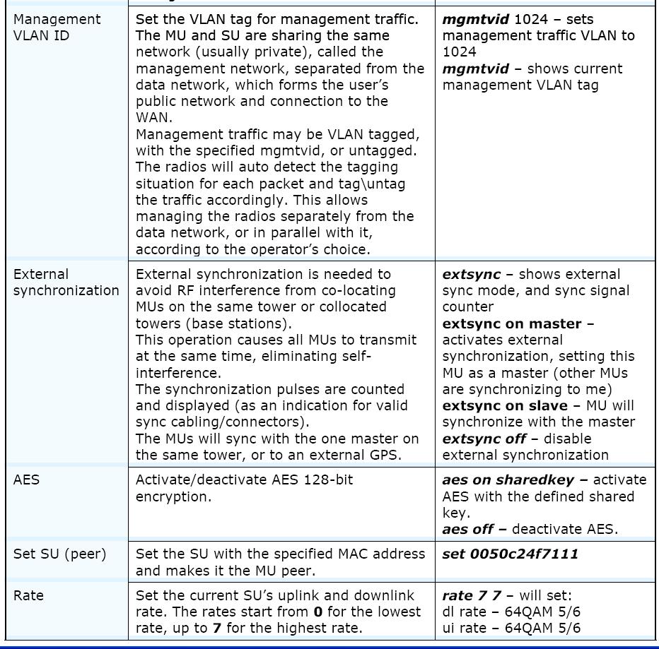
43 Page 42 of 48
44 5. Sygnus SHC Technical Specifications 5.1. Radio 5.2. Networking and Management 5.3. Physical and Environmental 20 MHz (dbm) Data 40 MHz (Mbps) PPS 50,000 Packets Per Second AIS Automatic Interference Sensibility ACM Adaptive Coding & Modulation ACS Automatic Channel Selection FEC Forward Error Correction, k = 1/2, 2/3, 3/4, 5/6 Fast ARQ Automatic Retransmit request Handling Interference and Range Up to 130 Km Net Throughput Up to 200 Mbps (100 Mbps Full Duplex) Data 10 MHz (Mbps) Data 5 MHz (Mbps) Data 20 MHz (Mbps) FEC 1/2 1/2 3/4 1/2 3/4 2/3 3/4 5/6 Modulation BPSK QPSK 16QAM 64QAM Encryption & Security 128-bit AES & MAC level authentication Output Power Configurable up to 26 dbm, 40 db dynamic range Waveform Advanced OFDM 2x2 dual polarization MIMO Channel Size Configurable 5 / 10 / 20 / 40 MHz Radio Frequency MHz, GHz, GHz, 4.9 GHz, 5.x GHz Topology Point-to-Point (PTP), Point-to-Multipoint (PTMP) VLAN Transparent or tagging/stripping QoS Based on 802.1q & 802.1p Management WEB, EMS, SNMP, Telnet, Built in throughput tests and RF Analyzer tools Access Technology Time Division Duplex (TDD) Dynamic or Symmetric Data Latency 1ms typical Traffic Handling Layer 2 transparent bridging Mechanical 19 x 19 x 4 cm (external antenna port) Operating Humidity 100% non-condensing (Rainproof) Power: Power over Ethernet (PoE) - 48 VDC VAC, Hz 10 x 5 x 2.5 cm PoE Adapter: Input Power Mechanical Mounting Wall or pole -30oc to 55oOperating Temperature c Power Consumption < 6Watt Connector Type RJ-45 Physical Interface 2 X 10/100 Base-T (ODU) Page 43 of 48
45 6. Technical Specifications 6.1. Radio 6.2. Networking and Management 6.3. Physical and Environmental Point-to-Point (PTP), Point-to-Topology Multipoint (PTMP) VLAN Transparent or tagging/stripping QoS Based on 802.1q & 802.1p Management WEB, EMS, SNMP, Telnet, Built in throughput tests and RF Analyzer tools Access Technology Time Division Duplex (TDD) Dynamic or Symmetric Data Latency 1ms typical Traffic Handling Layer 2 transparent bridging Encryption & Security 128-bit AES & MAC level authentication AIS Automatic Interference Sensibility ACM Adaptive Coding & Modulation ACS Automatic Channel Selection FEC Forward Error Correction, k = 1/2, 2/3, 3/4, 5/6 Fast ARQ Automatic Retransmit request and Handling Interference Output Power Configurable up to 26 dbm, 40 db dynamic range Waveform Advanced OFDM Channel Size Configurable 5 / 10 / 20 / 40 MHz Range Up to 130 Km PPS 50,000 Packets Per Second Radio Frequency MHz, GHz, GHz, 4.9 GHz, 5.x GHz 20 MHz (dbm) Data 40 MHz (Mbps) Net Throughput Sygnus SHC 1000/2000/ /40/120 Mbps Data 10 MHz (Mbps) Data 5 MHz (Mbps) Data 20 MHz (Mbps) FEC 1/2 1/2 3/4 1/2 3/4 2/3 3/4 5/6 Modulation BPSK QPSK 16QAM 64QAM Mechanical 19 x 19 x 4 cm (external antenna port) Operating Humidity 100% non-condensing (Rainproof) Power: Power over Ethernet (PoE) - 48 VDC VAC, Hz 10 x 5 x 2.5 cm PoE Adapter: Input Power Mechanical Mounting Wall or pole -30oc to 55oOperating Temperature c Power Consumption < 6Watt Connector Type RJ-45 Physical Interface 2 X 10/100 Base-T (ODU) Page 44 of 48
46 7. Appendix A Outdoor Cables Scheme Figure 34: Outdoor Cables Scheme Note: In order to comply with CAT5 91 meters cable Pins 1,2 must be on a twisted pair wire! Pins 3,6 must be on a twisted pair wire! Page 45 of 48

47 8. Appendix B RF Channel Lists 8.1. FCC operating Band: 5725 MHz MHz Page 46 of 48

48 9. Appendix C FCC Approved Antennas Figure 35: Integrated / external antennas for Sygnus SHC Page 47 of 48
March WaveIP Ltd. Teradion Industrial Park Misgav 20179, Israel Tel: Fax:
 WipAir 8000 Installation and Operation Instructions March 2015 The information contained in this document is of commercial value, proprietary to WaveIP. It is conveyed to the recipient solely for the purpose
RADWIN 2000 PORTFOLIO
 RADWIN 2000 PORTFOLIO Carrier-class point-to-point solutions The RADWIN 2000 portfolio offers sub-6 GHz licensed and unlicensed wireless broadband solutions that deliver from 25 Mbps and up to 750 Mbps
AW5802xTP. User s Manual. 5.8 GHz Outdoor Wireless Ethernet Panel. AvaLAN. Industrial-grade, long-range wireless Ethernet systems
 5.8 GHz Outdoor Wireless Ethernet Panel Industrial-grade, long-range wireless Ethernet systems AvaLAN W I R E L E S S Thank you for your purchase of the AW5802xTP 5.8 GHz Outdoor Wireless Ethernet Panel.
Point to Point PTP500
 Point to Point PTP500 The PTP Family of Products Product Family 2.5GHz 4.5GHz 4.9GHz 5.4GHz 5.8GHz Enhanced Max data rate EBS band DoD/Nato Public Safety Unlicensed Unlicensed IDU Mar'08 PTP600 Full 300Mbps
RADWIN 5000 JET NLOS PtP/PtMP HSU - Data Sheet. Product Highlights. Product Description RW-55S0-0550
 RADWIN 5000 JET NLOS PtP/PtMP HSU - Data Sheet RW-55S0-0550 Product Description Part of the RADWIN 5000 JET NLOS portfolio, RADWIN RW-55S0-0550 is a carrier class remote unit which is used for PtP and
Airmux-400 Broadband Wireless Multiplexer
 Data Sheet For North America Only Airmux-400 Point-to-point and multi point-to-point broadband radio solution for Cost-effective multi point-to-point encrypted wireless broadband multiplexer Net throughput
AW58300HTA AW58300HTS USER S MANUAL
 AW58300HTA AW58300HTS USER S MANUAL 5.8 GHz Outdoor 300 Mbps Wireless Ethernet Access Point and Subscriber Unit Radios Industrial-grade, long-range wireless Ethernet systems AvaLAN W I R E L E S S The
AW2400iTR USER S MANUAL 2.4 GHz Indoor Wireless Ethernet Radio
 USER S MANUAL 2.4 GHz Indoor Wireless Ethernet Radio Industrial-grade, long-range wireless Ethernet systems AvaLAN W I R E L E S S Thank you for your purchase of the AW2400iTR Indoor Wireless Ethernet
RIDE RADWIN 5000 HPMP HIGHWAY. RADWIN 5000 HPMP product brochure. RADWIN 5000 HPMP High Capacity Point to Multi-Point Solution
 RADWIN 5000 HPMP product brochure RIDE RADWIN 5000 HPMP HIGHWAY RADWIN 5000 HPMP High Capacity Point to Multi-Point Solution RADWIN 5000 HPMP delivers up to 200Mbps making it the ideal choice for last
Quick Start Guide. Version: 1.0 F/W: V1.2.0_RC1b. Date: December 11, 2017
 VigorAP 920R Series Ruggedized Outdoor AP with Extreme 802.11ac Power Warranty Quick Start Guide Version: 1.0 F/W: V1.2.0_RC1b Date: December 11, 2017 We warrant to the original end user (purchaser) that
AW5802xTR. User s Manual. 5.8 GHz Outdoor Wireless Ethernet Radio. AvaLAN. Industrial-grade, long-range wireless Ethernet systems
 AW5802xTR 5.8 GHz Outdoor Wireless Ethernet Radio Industrial-grade, long-range wireless Ethernet systems AvaLAN W I R E L E S S Thank you for your purchase of the AW5802xTR 5.8 GHz Outdoor Wireless Ethernet
RADWIN 5000 HPMP HIGH CAPACITY POINT TO MULTI-POINT. RADWIN 5000 HPMP product brochure RIDE RADWIN 5000 HPMP WIRELESS HIGHWAY
 RADWIN 5000 HPMP product brochure RADWIN 5000 HPMP HIGH CAPACITY POINT TO MULTI-POINT RIDE RADWIN 5000 HPMP WIRELESS HIGHWAY RADWIN 5000 HPMP Point-to-MultiPoint delivers up to 200Mbps per sector and is
MICHIGAN DEPARTMENT OF TRANSPORTATION SPECIAL PROVISION FOR TRAFFIC SIGNAL WIRELESS COMMUNICATIONS LINK
 MICHIGAN DEPARTMENT OF TRANSPORTATION SPECIAL PROVISION FOR TRAFFIC SIGNAL WIRELESS COMMUNICATIONS LINK SIG:CJS 1 of 6 APPR:EMS:DBP:06-29-17 FHWA:APPR:08-14-17 a. Description. This work consists of completing
MICHIGAN DEPARTMENT OF TRANSPORTATION SPECIAL PROVISION FOR TRAFFIC SIGNAL WIRELESS COMMUNICATIONS LINK
 MICHIGAN DEPARTMENT OF TRANSPORTATION SPECIAL PROVISION FOR TRAFFIC SIGNAL WIRELESS COMMUNICATIONS LINK SIG:EMS 1 of 6 APPR:LWB:DBP:07-14-15 FHWA:APPR:07-28-15 a. Description. This work consists of site
AvaLAN AW58103HTS MANUAL ADDENDUM. 5.8 GHz Outdoor 100 Wireless 3-Port Ethernet Subscriber Unit Radio
 AW58103HTS MANUAL ADDENDUM 5.8 GHz Outdoor 100 Wireless 3-Port Ethernet Subscriber Unit Radio Industrial-grade, long-range wireless Ethernet systems AvaLAN W I R E L E S S AW58103HTS Addendum The AW58103HTS
AW900xTR USER S MANUAL 900 MHz Outdoor Wireless Ethernet Radio
 USER S MANUAL 900 MHz Outdoor Wireless Ethernet Radio Industrial-grade, long-range wireless Ethernet systems Thank you for your purchase of the AW900xTR Outdoor Wireless Ethernet Radio. The AW900xTR includes:
TT-208. User s Manual. 300Mps 5.8 GHz. IP Camera Wireless Transmission Kit
 TT-208 300Mps 5.8 GHz IP Camera Wireless Transmission Kit User s Manual V1.0 02 / 2014 Welcome Thank you for purchasing the TT-208 Wireless Transmission Kit for IP Cameras. This user s manual is designed
AW900F AW900F-PAIR USER S MANUAL
 AW900F AW900F-PAIR USER S MANUAL 900 MHz Industrial Wireless Ethernet Radios Industrial-grade, long-range wireless Ethernet systems AvaLAN W I R E L E S S Thank you for your purchase of the AW900F Indoor
RADWIN 2000 Portfolio. Built for Backhaul
 RADWIN 2000 cellular backhaul deployment RADWIN 2000 Portfolio Built for Backhaul The RADWIN 2000 portfolio of carrier-class sub-6 GHz products delivers ultra-capacity for long-ranges. Built for Backhaul,
RADWIN 5000 JET REDEFINING POINT-TO-MULTIPOINT WIRELESS CONNECTIVITY IN SUB-6GHZ BANDS
 RADWIN 5000 JET POINT-TO-MULTIPOINT Product Brochure PtMP solution with PtP performance 750 Mbps RADWIN 5000 JET REDEFINING POINT-TO-MULTIPOINT WIRELESS CONNECTIVITY IN SUB-6GHZ BANDS RADWIN 5000 JET is
RADWIN JET POINT-TO-MULTIPOINT BEAMFORMING SOLUTION DELIVERS FIBER-LIKE CONNECTIVITY FOR RESIDENTIAL AND ENTERPRISE
 RADWIN JET POINT-TO-MULTIPOINT FOR SERVICE PROVIDERS Product Brochure PtMP solution with PtP performance 750 Mbps RADWIN JET POINT-TO-MULTIPOINT BEAMFORMING SOLUTION DELIVERS FIBER-LIKE CONNECTIVITY FOR
AW900i. User s Manual. Point-to-point. Industrial-grade, ultra-long-range 900 MHz non-line-of-sight wireless Ethernet systems
 Point-to-point Industrial-grade, ultra-long-range 900 MHz non-line-of-sight wireless Ethernet systems Non-line-of-sight :: 900 MHz Thank you for your purchase of the point-to-point wireless Ethernet bridge.
3 GHz Carrier Backhaul Radio. Model: AF-3X. Tel: +44 (0) Fax: +44 (0) LINK GPS MGMT DATA DATA
 Fax: +44 (0) LINK GPS MGMT DATA DATA") LINK GPS MGMT DATA DATA MGMT GPS LINK 3 GHz Carrier Backhaul Radio Model: AF-3X LINK GPS MGMT DATA 3 GHz Carrier Backhaul Radio Model: AF-3X LINK GPS MGMT DATA DATA MGMT GPS LINK Introduction Thank you
LINK GPS MGMT DATA DATA MGMT GPS LINK 3 GHz Carrier Backhaul Radio Model: AF-3X LINK GPS MGMT DATA 3 GHz Carrier Backhaul Radio Model: AF-3X LINK GPS MGMT DATA DATA MGMT GPS LINK Introduction Thank you
ORiNOCO AP-4000MR-LR and AP-4900MR-LR Access Points Safety and Regulatory Compliance Information
 IMPORTANT! Visit http://support.proxim.com for the latest safety and regulatory compliance information for this product. ORiNOCO AP-4000MR-LR and AP-4900MR-LR Access Points Safety and Regulatory Compliance
500 Series AP and SM CAP and CSM Licensed, Reliable Wireless Connectivity
 500 Series AP and SM CAP 35500 and CSM 35500 Licensed, Reliable Wireless Connectivity Reliable, Cost Effective Connectivity 3.5 GHz Licensed Band OFDM nlos and NLOS Connectivity High Downlink AND Uplink
MATERIAL SPECIFICATIONS FOR WIRELESS LINK
 MATERIAL SPECIFICATIONS FOR WIRELESS LINK SECTION 1 GENERAL The Wireless Link specification is for the listed components to be used in the Wireless Link pay item. Each component includes the antennae and
System Specification. BreezeACCESS TM EZ. January 2008
 System Specification BreezeACCESS TM EZ January 2008 All rights reserved Alvarion Ltd 2008 The information contained in this document is the proprietary and exclusive property of Alvarion Ltd. except as
APC 2M-14 Quick Installation Guide
 APC 2M-14 Quick Installation Guide Revision 1.4 20 October 2011 Copyright 2011 Deliberant www.deliberant.com Copyright 2011 Deliberant This user s guide and the software described in it are copyrighted
Cambium PMP 450 Series PMP 430 / PTP 230 Series PMP/PTP 100 Series Release Notes
 POINT TO POINT WIRELESS SOLUTIONS GROUP Cambium PMP 450 Series PMP 430 / PTP 230 Series PMP/PTP 100 Series Release Notes System Release 13.1.3 1 INTRODUCTION This document provides information for the
LigoDLB MACH 5. 5 GHz high-capacity wireless device COPYRIGHT 2017 LIGOWAVE
 LigoDLB MACH 5 5 GHz high-capacity wireless device Incredible performance 5+ Mbps throughput - a result of powerful hardware platform with 82.11ac technology based radio and a proprietary data transmission
USER S MANUAL ADDENDUM Matched Pair Bridges
 USER S MANUAL ADDENDUM Matched Pair Bridges Certain AvaLAN radios are sold as matched pairs, pre-configured as a wireless Ethernet bridge. The manual supplied with the pair does not include information
PYRAMID 915MHZ WIRELESS RF TRANSMITTER & REPEATER USER GUIDE. Table of Contents. Overview Installation Setup Specifications...
 Table of Contents Overview................................... 1 Installation.................................. 1 Setup...................................... 2 Specifications..............................
RADWIN JET PtMP Beamforming solution delivers fiber-like connectivity for residential and enterprise. 750 Mbps. PtMP solution with PtP performance
 RADWIN JET Point-to-MultiPoint for Service Providers Product Brochure PtMP solution with PtP performance 750 Mbps RADWIN JET PtMP Beamforming solution delivers fiber-like connectivity for residential and
DIGICELL ANYNET NETWORK ACCESS MODULE
 Comm Activity Network Status Service DigiCell Any NET Network Access Module Network Interface Network Service AMPS Cellemetry GSM SMS CDMA GPRS Ethernet 1xRTT RS-232 TCP/IP Input 1 Standard S3 off, S4
RADWIN 2000 PORTFOLIO CARRIER-CLASS POINT-TO-POINT SOLUTIONS. RADWIN 2000 product portfolio
 RADWIN 00 product portfolio RADWIN 00 PORTFOLIO CARRIER-CLASS POINT-TO-POINT SOLUTIONS RADWIN 00 CARRIER-CLASS SUB-6 GHZ POINT-TO-POINT PORTFOLIO IS IDEAL FOR CARRIERS AND A VARIETY OF VERTICAL MARKETS
Airmux-400 Specifications
 Airmux-400 Specifications Configuration Architecture Outdoor Units (ODUs) Max Throughput ODU: Outdoor Unit with Integrated Antenna, Embedded Antenna or Connectorized Unit for External Antenna IDU: Indoor
INSTALLATION AND OPERATING MANUAL
 INSTALLATION AND OPERATING MANUAL FOR RBDA-PCS-1/25W-90-A INDOOR REPEATER TABLE OF CONTENTS PARAGRAPH PAGE NO BDA OVERVIEW 3 BDA BLOCK DIAGRAM DESCRIPTION 3 FCC INFORMATION FOR USER 3 BDA BLOCK DIAGRAM
LINK GPS MGMT DATA. 4 GHz Licensed Backhaul Radio DATA MGMT GPS. Model: AF-4X LINK
 LINK GPS MGMT DATA DATA MGMT GPS LINK 4 GHz Licensed Backhaul Radio Model: AF-4X 4 GHz Licensed Backhaul Radio Model: AF-4X LINK GPS MGMT DATA DATA MGMT GPS LINK Introduction Thank you for purchasing the
GC9838-LR - INTELLIGENT HYBRID PLC-RF DIN RAIL MODEM
 GC9838-LR - INTELLIGENT HYBRID PLC-RF DIN RAIL MODEM and a built-in sub-ghz wireless module to allow adaptive networking over different media. The wireless connectivity can be available in LoRa for tree-structure
11 GHz FDD Licensed Backhaul Radio. Model: AF 11FX
 11 GHz FDD Licensed Backhaul Radio Model: AF 11FX 11 GHz FDD Licensed Backhaul Radio Model: AF 11FX Introduction Thank you for purchasing the Ubiquiti Networks airfiber AF 11FX. This Quick Start Guide
RM24100A. *Maximum transmit power output levels and local radio frequency regulator bodies must be obeyed in the country of operation.
 RM24100A 2.4GHz 100mW RS232 / RS485 / RS422 DSSS Radio Modem (IEEE 802.15.4 compliant) Operating Manual English 1.02 Introduction The RM24100A radio modem acts as a wireless serial cable replacement and
GPSR400 Quick Start Guide
 GPSR400 Quick Start Guide Rev. 6 Introduction Microlab s digital GPS repeater system can be used for cellular communications UTC synchronization for locations where the GPS signals are not readily available.
Connecting the Radio:
 Connecting the Radio: Step 1: Connect the Cat5 cable from the radio into the RJ-45 jack marked CPE on the POE injector. The POE injector is not weather proof and should be installed indoors. Step 2: Connect
RADWIN 2000 PORTFOLIO BUILT FOR BACKHAUL. RADWIN 2000 product portfolio
 RADWIN 2 product portfolio RADWIN 2 PORTFOLIO BUILT FOR BACKHAUL RADWIN 2 CARRIER-CLASS SUB-6 GHZ POINT-TO-POINT PORTFOLIO IS IDEAL FOR CARRIERS AND A VARIETY OF VERTICAL MARKETS THAT REQUIRE HIGH CAPACITY
RADWIN JET PtMP Beamforming solution delivers fiber-like connectivity for residential and enterprise. 750 Mb
 RADWIN JET Point-to-MultiPoint for Service Providers Product Brochure PtMP so l with PtuPtion perform ance 750 Mb ps RADWIN JET PtMP Beamforming solution delivers fiber-like connectivity for residential
RADWIN JET PtMP Beamforming solution for fiber-like connectivity
 RADWIN JET Point-to-MultiPoint for Private Networks Product Brochure PtMP so l with PtuPtion perform ance 750 Mb ps RADWIN JET PtMP Beamforming solution for fiber-like connectivity RADWIN JET is a disruptive
GPSR116 Quick Start Guide
 GPSR116 Quick Start Guide .21 [ 5,3] [482,6] 18.12 [460,3] GPSR116 Quick Start Guide Rev 2.35 [8,9] Introduction Microlab s digital GPS repeater system can be used for cellular communications UTC synchronization
VueNet EasyLink. ver User`s manual External wireless video and audio transmission system for IP cameras HD and UHD in the band
 VueNet EasyLink ver. 1.2 User`s manual External wireless video and audio transmission system for IP cameras HD and UHD in the band 5.1-5.8 GHz Thank you for choosing the VueNet EasyLink. We trust that
Pro Range SIL PICO SIL MICRO SIL LITE SIL MAX SIL BASE. 5.1GHz 5.8GHz Wireless Links
 +44 (0) 800 6521629 sales@silvernet.com www.silvernet.com Pro Range SIL PICO SIL MICRO SIL LITE SIL MAX SIL BASE 5.1GHz 5.8GHz Wireless Links OVERVIEW The PRO Range is a class leading outdoor wireless
System Requirements: D-Link Systems, Inc.
 System Requirements: Minimum System Requirements: CD-ROM Drive Computers with Windows, Macintosh, or Linux-based operating systems Installed Ether net Adapter Internet Explorer version 6.0 or Netscape
RM24100D. Introduction. Features. 2.4GHz 100mW RS232 / RS485 / RS422 DSSS Radio Modem (IEEE compliant) Operating Manual English 1.
 Operating Manual English 1.") RM24100D 2.4GHz 100mW RS232 / RS485 / RS422 DSSS Radio Modem (IEEE 802.15.4 compliant) Operating Manual English 1.09 Introduction The RM24100D radio modem acts as a wireless serial cable replacement and
RM24100D 2.4GHz 100mW RS232 / RS485 / RS422 DSSS Radio Modem (IEEE 802.15.4 compliant) Operating Manual English 1.09 Introduction The RM24100D radio modem acts as a wireless serial cable replacement and
Datasheet. Licensed Backhaul Radio. Model: AF-4X. Up to 687 Mbps Real Throughput, Up to 200+ km Range
 Licensed Backhaul Radio Model: AF-4X Up to 687 Mbps Real Throughput, Up to 200+ km Range Optimal Use of 4.9 GHz Radio Band for Public Safety Sector Ubiquiti s INVICTUS Custom Silicon Overview Ubiquiti
Quick Start Guide. Antenna Alignment Tool AIMWLLR0-35. QSG rev 7 AIMWLLR0-35 [NRB-0200] QSG.indd 1
![Quick Start Guide. Antenna Alignment Tool AIMWLLR0-35. QSG rev 7 AIMWLLR0-35 [NRB-0200] QSG.indd 1](/thumbs/86/94268876.jpg "Quick Start Guide. Antenna Alignment Tool AIMWLLR0-35. QSG rev 7 AIMWLLR0-35 [NRB-0200] QSG.indd 1") Quick Start Guide Antenna Alignment Tool AIMWLLR0-35 QSG-00097 rev 7 AIMWLLR0-35 [NRB-0200] QSG.indd 1 Welcome This quick start guide is designed to familiarize you with the features and use of the NetComm
Quick Start Guide Antenna Alignment Tool AIMWLLR0-35 QSG-00097 rev 7 AIMWLLR0-35 [NRB-0200] QSG.indd 1 Welcome This quick start guide is designed to familiarize you with the features and use of the NetComm
RADWIN 5000 HPMP HIGH CAPACITY POINT-TO-MULTIPOINT. RADWIN 5000 HPMP product brochure RIDE THE RADWIN 5000 HPMP WIRELESS HIGHWAY
 RADWIN 5000 HPMP product brochure RADWIN 5000 HPMP HIGH CAPACITY POINT-TO-MULTIPOINT RIDE THE RADWIN 5000 HPMP WIRELESS HIGHWAY The RADWIN 5000 high-capacity Point-to-Multipoint (HPMP) solution delivers
RM600 Carrier Grade E1 Radios
 Carrier Grade E1 Radios Quick Start Guide Package Contents ODU 1 IDU 1 Mast/Wall Mounting Kit 1 Outdoor Ethernet Cable (Optional) 1 External Antenna (Optional) 1 Power Supply Cable 1 Quick Start Guide
User's Manual F10G-5S-LCD 1 / 20 BOOST CELL PHONE SIGNAL BOOSTERS MADE BY HUAPTEC
 User's Manual F10G-5S-LCD 1 / 20 BOOST CELL PHONE SIGNAL BOOSTERS MADE BY HUAPTEC Table of contents WHAT IS INCLUDED... 3 1 HOW IT WORKS... 3 2 TOOL REQUIRED... 3 3 HOW TO INSTALL YOUR NEW CELLULAR BOOSTER...
(ES) Equipements Scientifiques SA - Département Réseaux sans fil rue de Buzenval BP Garches Tél Fax.
 Equipements Scientifiques SA - Département Réseaux sans fil rue de Buzenval BP Garches Tél Fax.") (ES) Equipements Scientifiques SA - Département Réseaux sans fil - 127 rue de Buzenval BP 26-92380 Garches Tél. 01 47 95 99 50 - Fax. 01 47 01 16 22 - e-mail: reseaux@es-france.com - Site Web: www.es-france.com
(ES) Equipements Scientifiques SA - Département Réseaux sans fil - 127 rue de Buzenval BP 26-92380 Garches Tél. 01 47 95 99 50 - Fax. 01 47 01 16 22 - e-mail: reseaux@es-france.com - Site Web: www.es-france.com
Airmux-400 Broadband Wireless Multiplexer (Ver. 2.4)
") Data Sheet For North America Only Airmux-400 Point-to-point and multi point-to-point broadband radio solution for Ethernet and TDM traffic over license-free frequencies Cost-effective multi point-to-point
Data Sheet For North America Only Airmux-400 Point-to-point and multi point-to-point broadband radio solution for Ethernet and TDM traffic over license-free frequencies Cost-effective multi point-to-point
TrangoFOX Subscriber Unit. (for Access5830 Wireless Broadband System) User Manual
 User Manual") TrangoFOX Subscriber Unit (for Access5830 Wireless Broadband System) User Manual Overview This manual covers basic configuration and installation of TrangoFOX Subscriber Units for the Access5830 Wireless
TrangoFOX Subscriber Unit (for Access5830 Wireless Broadband System) User Manual Overview This manual covers basic configuration and installation of TrangoFOX Subscriber Units for the Access5830 Wireless
Wireless Z-Wave Control ZRP-100US Z-Wave Repeater USER MANUAL. Introduction
 Wireless Z-Wave Control ZRP-100US Z-Wave Repeater USER MANUAL Introduction Thank you for choosing ZRP-100 Z-Wave Repeater product! ZRP-100 is a Z-Wave repeater with best RF performance to repeat Z-Wave
Using the epmp Link Budget Tool
 Using the epmp Link Budget Tool The epmp Series Link Budget Tool can offer a help to determine the expected performances in terms of distances of a epmp Series system operating in line-of-sight (LOS) propagation
Power Genius XL User Manual rev 10.
 Power Genius X User Manual rev 10. 1/23 Table of Contents 0. Important notice...3 1. Unpacking...5 1.1. Front Panel...5 1.2. Back Panel...6 1.3. BCD/PTP connector pinout...8 2. Using with Radios...9 2.1.
AW900-SPEC USER S MANUAL
 USER S MANUAL 900 MHz Site Survey Spectrum Analyzer Industrial-grade, long-range wireless Ethernet systems AvaLAN W I R E L E S S User s Manual Thank you for your purchase of the AW900-SPEC Site Survey
NetPoint Pro. 6x2.4, 6x5.8, 3x2.4, 3x5.8. Wi-Fi base Stations Providing Superior Connectivity
 NetPoint Pro 6x2.4, 6x5.8, 3x2.4, 3x5.8 Wi-Fi base Stations Providing Superior Connectivity NetPoint Pro is an advanced Wi-Fi base station that provides superior connectivity and greater range. It enables
High Security Supplement
 High Security Supplement User Manual Supplement foravalan Wireless Radios with FIPS 140-2 Security AW900FS USER S MANUAL Industrial-grade, long-range wireless Ethernet systems AvaLAN W I R E L E S S High
INSTRUCTION MANUAL. IBRit - rf1 - usb PC - Station for wireless Data transmission. M e s s t e c h n i k. Messtechnik GmbH & Co.
 M e s s t e c h n i k INSTRUCTION MANUAL PC - Station for wireless Data transmission Document No. : D1F604 001 Version : April 2006 Copyright : IBR Messtechnik GmbH & Co. KG Contents 1. Introduction 1.1
LigoSU 5-N/ 5-20/ 5-23
 LigoSU 5-N/ 5-2/ 5-23 High-performance 5 GHz subscriber unit COPYRIGHT 217 LIGOWAVE COPYRIGHT 217 LIGOWAVE Available models LigoSU 5-N LigoSU 5-2 LigoSU 5-23 Subscriber unit with N-type connectors for
USER MANUAL Digital Wireless Gateway U9120-W4 (P/N: 44002G-01)
") USER MANUAL Digital Wireless Gateway U9120-W4 (P/N: 44002G-01) 19549P-82 (11-16) 2016 DAVID CLARK COMPANY INCORPORATED Cautions and Warnings READ AND SAVE THESE INSTRUCTIONS. Follow the instructions in
USER MANUAL Digital Wireless Gateway U9120-W4 (P/N: 44002G-01) 19549P-82 (11-16) 2016 DAVID CLARK COMPANY INCORPORATED Cautions and Warnings READ AND SAVE THESE INSTRUCTIONS. Follow the instructions in
AW5800-SPEC USER S MANUAL
 USER S MANUAL 5.8 GHz Site Survey Spectrum Analyzer Industrial-grade, long-range wireless Ethernet systems AvaLAN W I R E L E S S User s Manual Thank you for your purchase of the AW5800-SPEC Site Survey
HORNET Remote Control Systems
 HORNET Remote Control Systems Up to 100metres Range 1 3 Button versions 12-30Vdc 0r 230Vac versions Reliable FM Technology Up to four 1000W Relay switches Waterproof Receiver (IP68) Momentary or Latching
Disclaimers. Important Notice
 Disclaimers Disclaimers Important Notice Copyright SolarEdge Inc. All rights reserved. No part of this document may be reproduced, stored in a retrieval system, or transmitted, in any form or by any means,
TrangoLINK-45 Point-to-Point Wireless Ethernet Bridge USER MANUAL
 TrangoLINK-45 Point-to-Point Wireless Ethernet Bridge USER MANUAL August, 2011 Revision 2p0r3 Contents Preface... 4 FCC Information... 4 Industry Canada Information... 5 Warranty Information... 5 European
Interface Manual Tank Level Float Stick System
 1 Interface Manual Tank Level Float Stick System SignalFire Model: Sentinel-FS-3BIS The SignalFire Sentinel Float Stick Node is an Intrinsically Safe device with the following features: - Standard SignalFire
Airmux-400 Broadband Wireless Multiplexer (Ver )
") Data Sheet For North America Only Airmux-400 Broadband Wireless Multiplexer (Ver. 2.4.50) Cost-effective multiple point-to-point encrypted broadband wireless multiplexer Point-to-point and multiple point-to-point
Data Sheet For North America Only Airmux-400 Broadband Wireless Multiplexer (Ver. 2.4.50) Cost-effective multiple point-to-point encrypted broadband wireless multiplexer Point-to-point and multiple point-to-point
FSW-1650 FSW User Manual. 16/24-Port 10/100 Rackmount Switch
 FSW-1650 FSW-2450 User Manual 16/24-Port 10/100 Rackmount Switch V1.0.0.0810 COPYRIGHT & TRADEMARKS Specifications are subject to change without notice. LevelOne is a registered trademark of Digital Data
Instruction manual ADN-W AM. Antenna Module
 Instruction manual ADN-W AM Antenna Module For your safety www www.sennheiser.com Manual Contents For your safety... 1 The ADN-W AM antenna module... 1 Package contents... 2 Components required for wireless
1000 Integrated Radio
 SPECIFICATION SHEET: epmp 1000 INTEGRATED RADIO 1000 Integrated Radio Network operators are challenged to deliver reliable connectivity in overcrowded RF environments. As available spectrum becomes more
Memorylink UltraSync GPS-100M Synchronization Guide. for PTP 600 Series Wireless Ethernet Bridges
 Memorylink UltraSync GPS-100M Synchronization Guide for PTP 600 Series Wireless Ethernet Bridges Contents pg Section 3 Introduction 4 System Overview 5 Product Features and Benefits 6 Installation The
WPR400 Wireless Portable Reader
 P516-098 WPR400 Wireless Portable Reader User guide Para el idioma español, navegue hacia www.schlage.com/support. Pour la portion française, veuillez consulter le site www.schlage.com/support. Contents
Copyright Teletronics International, Inc. Patent Pending
 Copyright 2003 By Teletronics International, Inc. Patent Pending FCC NOTICES Electronic Emission Notice: This device complies with Part 15 of the FCC rules. Operation is subject to the following two conditions:
Ffirm. Atlas5010 Point-to-Point Wireless Ethernet Bridge USER MANUAL. April 25, 2005 Revision 2
 Ffirm Atlas5010 Point-to-Point Wireless Ethernet Bridge USER MANUAL April 25, 2005 Revision 2 Table of Contents Trango Table of Contents Preface...iv FCC Information...iv Warranty Information...iv Contact
900 MHz. Frequency Hopping RS-485 Master/Slave auto-sensing radio interface.
 MDR210A-485 900 MHz. Frequency Hopping RS-485 Master/Slave auto-sensing radio interface. Black Box Corporation Lawrence, PA - http://www.blackbox.com - Ph 877-877-BBOX - Fax 724-746-0746 Table of Contents
MPR kHz Reader
 MPR-5005 Page 1 Doc# 041326 MPR-5005 125kHz Reader Installation & Operation Manual - 041326 MPR-5005 Page 2 Doc# 041326 COPYRIGHT ACKNOWLEDGEMENTS The contents of this document are the property of Applied
Quick Start Guide. ELPRO 905U-L-T Wireless I/O Transmitter Unit. man_905u-l-t_quickstart_v1.9.doc
 Quick Start Guide ELPRO 905U-L-T Wireless I/O Transmitter Unit man_905u-l-t_quickstart_v1.9.doc About this document This document is the and contains the following sections: Section Basic steps for using
JetWave WIFI Module Industrial 2.4G n 2.4G/ 5G ac mpcie WIFI module
 JetWave WIFI Module Industrial 2.4G 802.11n 2.4G/ 5G 802.11ac mpcie WIFI module User Manual V1.0 Aug. 2016 JetWave WIFI Module User Manual Copyright Copyright 2016 all rights reserved. No part of this
Setup Guide. support.spruceirrigation.com.
 FCC Compliance Statement This device complies with Part 15 of the FCC Rules. Operation is subject to the following two conditions: (1) this device may not cause harmful interference, and (2) this device
802.16s SOFTWARE PLATFORM
 General Software s 802.16s SOFTWARE PLATFORM Architecture Operation system Embedded Linux 1. MAC layer application running on ARM processor 2. PHY layer application running on DSP Application software
Datasheet. 5 GHz Carrier Backhaul Radio. Model: AF-5X. Up to 500+ Mbps Real Throughput, Up to 200+ km Range. Full-Band Certification including DFS
 5 GHz Carrier Backhaul Radio Model: AF-5X Up to 500+ Mbps Real Throughput, Up to 200+ km Range Full-Band Certification including DFS Ubiquiti s INVICTUS Custom Silicon Overview Ubiquiti Networks continues
Doodle Labs Smart Radio RM-2450 SWaP Optimized COFDM/MIMO Broadband Radio with Ethernet
 Doodle Labs Smart Radio RM-2450 SWaP Optimized COFDM/MIMO Broadband Radio with Ethernet Smart Radio Overview The Smart Radio is a tiny, full-featured broadband MIMO radio and a mesh router. It has an Ethernet
AERO MP100 High Performance Point to Point & Point to Multipoint Products
 AERO MP100 High Performance Point to Point & Point to Multipoint Products Best in class PTP & PTMP with high built-in quality MIMO 2x2 and dynamic spectrum analysis with zero downtime Mobility management
Enphase. Mobile Connect Installation Guide
 Enphase Mobile Connect Installation Guide Mobile Connect Installation Guide Contact Information Enphase Energy Inc. 1420 N. McDowell Blvd. Petaluma, CA 94954 http://www.enphase.com support@enphaseenergy.com
AN0509 swarm API Country Settings
 1.0 NA-15-0356-0002-1.0 Version:1.0 Author: MLA Document Information Document Title: Document Version: 1.0 Current Date: 2015-04-16 Print Date: 2015-04-16 Document ID: Document Author: Disclaimer NA-15-0356-0002-1.0
BRU-100 Physical Installation
 APPENDIX B BRU-100 In This Appendix: Warnings and Cautions, page 50, page 51 Check List, page 57 This appendix provides guidance for the physical installation of the BRU-100 Remote Unit at a subscriber
ver. 1.2 User`s manual External wireless video and audio transmission system for IP cameras HD and UHD in the band GHz
 ver. 1.2 User`s manual External wireless video and audio transmission system for IP cameras HD and UHD in the band 5.1 5.8 GHz www.camsat.com Thank you for choosing the CDS-EasyIP. Eco. We trust that its
Doodle Labs Smart Radio RM-1370 SWaP Optimized COFDM/MIMO Broadband Radio with Ethernet
 Doodle Labs Smart Radio RM-1370 SWaP Optimized COFDM/MIMO Broadband Radio with Ethernet Smart Radio Overview The Smart Radio is a tiny, full-featured broadband MIMO radio and a mesh router. It has an Ethernet
900 MHz Digital Wireless Indoor/Outdoor Speakers
 4015007 900 MHz Digital Wireless Indoor/Outdoor Speakers User s Manual This 900 MHz digital hybrid wireless speaker system uses the latest wireless technology that enables you to enjoy music and TV sound
Manual Unihan UPWL6580
 Manual Unihan UPWL6580 Federal Communications Commission Statement This device complies with FCC Rules Part 15. Operation is subject to the following i. This device may not cause harmful interference,
Ffirm. TrangoLINK-45 Point-to-Point Wireless Ethernet Bridge USER MANUAL. June, 2007 Revision 1p3
 Ffirm TrangoLINK-45 Point-to-Point Wireless Ethernet Bridge USER MANUAL June, 2007 Revision 1p3 Preface Table of Contents Preface...iv FCC Information...iv Industry Canada Information... v Warranty Information...
USER'S MANUAL. Model : K
 USER'S MANUAL Model : 2000-64K TM GINA MODEL 2000-64K Overview GINA Model 2000-64K is a stand-alone, high frequency data transceiver using spread spectrum technology. GINA 2000-64K capabilities include
AcuMesh Wireless RS485 Network. User's Manual SOLUTION
 AcuMesh Wireless RS485 Network User's Manual AN SOLUTION ACUMESH - WIRELESS METERING SYSTEM COPYRIGHT 2015 V1.2 This manual may not be altered or reproduced in whole or in part by any means without the