Clamp-on Fixed Type Ultrasonic Flowmeter
|
|
|
- Natalie Booker
- 5 years ago
- Views:
Transcription


1 Clamp-on Fixed Type Ultrasonic Flowmeter TFUF-TTCL
2 Contents 1. Introduction P4 1.1 Preface P4 1.2 Features P4 1.3 Flow measurement principle P4 1.4 Optional transducer P5 1.5 Typical application P5 1.6 Product Identification P6 1.7 Specifications P6 2. Installation and Measurement P7 2.1 Wiring diagram P7 2.2 Keypad P7 2.3 Menu Windows P8 2.4 Steps to Configure the Parameters P9 2.5 Transducers Straight Pipe Requirements P Transducers Installation P Wiring diagram of transducer P Transducers Spacing P V-method Installation P Z-method Installation P W-method Installation P N-method Installation P Installation Checkup P Signal Strength P Signal quality P Time Ratio between the Measured Total Transit Time and the Calculated Time P14 3. Menu Window Details P Menu Windows Arrangement P Menu Window Details P16 4. How To P How to judge if the instrument works properly P How to judge the liquid flowing direction P How to change between units systems P How to select a required flow rate unit P How to use the totalizer multiplier P24
3 4.6 How to open or shut the totalizers P How to reset the totalizers P How to restore the flow meter with default setups P How to use the damper P How to use the zero-cutoff function P How to setup a zero point P How to get a scale factor for calibration P How to use the system locker P How to use 4-20mA current loop output P How to use the Frequency Output P How to use the Totalizer Pulse Output P How to produce an alarm signal P How to use the built-in Buzzer P How to use the OCT output P How to modify the built-in calendar P How to view the Date Totalizers P How to use the Working Timer P How to use the manual totalizer P How to know how long the battery will last P How to check the ESN and other minor details P How to use the data logger for scheduled output P How to output analogue voltage signal P How to adjust the LCD display P How to use RS232/RS485 P How to use automatic amending function for offline compensation P How to use batch controller P How to adjust the analogue output P How to solidify the parameters P How to enter the parameters of user-type-transducer P How to use the circular display function P How to enter into the linearity correcting? How to enter into the data? P How to save / restore frequently-used pipe parameters P32 5. Troubleshooting P Power-on Error Displays and Counter-Measures P Error Code and Counter-Measures P Other Problems and Solutions P33
4 1. Introduction 1.1 Preface Welcome to use new generation transit-time ultrasonic flow meter, please read the user manual carefully before using. The wall-mount ultrasonic flow meter is designed to be installed in a fixed location for longterm flow measurement. 1.2 Features Linearity: 0.5%, Repeatability: 0.2% Accuracy:±1% Easy to operate. Several type transducers for selection, measuring pipe size is from DN15mm to DN6000mm Adopt low voltage, multi-pulse technology to improve accuracy, useful life and reliability. Powerful Recording Function, record the totalizer data of the last 64 days/64 monthes/5 years. 1.3 Flow measurement principle The TFUF-TTCL ultrasonic flow meter is designed to measure the fluid velocity of liquid within a closed conduit. The transducers are a non-contacting, clamp-on type, which will provide benefits of non-fouling operation and easy installation. The TFUF-TTCL transit-time flow meter utilizes two transducers that function as both ultrasonic transmitters and receivers. The transducers are clamped on the outside of a closed pipe at a specific distance from each other. The transducers can be mounted in V-method where the sound transverses the pipe twice, or Wmethod where the sound transverses the pipe four times, or in Z-method where the transducers are mounted on opposite sides of the pipe and the sound crosses the pipe once. This selection of the mounting method depends on pipe and liquid characteristics. The flow meter operates by alternately transmitting and receiving a frequency modulated burst of sound energy between the two transducers and measuring the transit time that it takes for sound to travel between the two transducers. The difference in the transit time measured is directly and exactly related to the velocity of the liquid in the pipe, show as follows:
5 1.4 Optional transducer TS-1 clamp-on type transducer, pipe size from DN15-100mm TM-1 clamp-on type transducer, pipe size from DN mm TL-1 clamp-on type transducer, pipe size from DN mm HTS-1 clamp-on type transducer, pipe size from DN15-100mm (high temperature) HTM-1 clamp-on type transducer, pipe size from DN mm (high temperature) HTL-1 clamp-on type transducer, pipe size from DN mm (high temperature) 1.5 Typical application The wall-mounting flow meter can be applied to a wide range of pipe flow measurements. Applicable liquids include pure liquids as well as liquid with small quantity of tiny particles. Examples are: Water (hot water, chilled water, city water, sea water, waste water, etc.); Sewage with small particle content; Oil (crude oil, lubricating oil, diesel oil, fuel oil, etc.); Chemicals (alcohol, acids, etc.); Plant effluent; Beverage, liquid food; Ultra-pure liquids; Solvents and other liquids

6 1.6 Product Identification Each set of the flow meter has a unique product identification number or ESN (electronic serial number) written into the software that can only be modified with a special tool by the manufacturer. In case of any hardware failure, please provide this number which is located on menu window M61 when contacting the manufacturer. 1.7 Specifications
 is the going UP key, when the user wants to go to the upper menu window.")
7 2. Installation and Measurement 2.1 Wiring diagram 2.2 Keypad The keypad for the operation of the flow meter is as shown by the right picture. Keys 0-9 and. are keys to enter numbers Key ( /+) is the going UP key, when the user wants to go to the upper menu window. It also works as the + key when entering numbers Key ( /- )is the going DOWN key, when the user wants to go down-sided menu window. It also works as the key when entering numbers. Key ( )is backspace key, when the user wants go left or wants backspace the left character that is located to the left of the cursor.
8 Key ENT is the ENTER key for any inputting or selections. Key MENU is the key for the direct menu window jump over. Whenever the user wants to proceed to a certain menu window, the user can press this key followed by 2-digit numbers. The MENU key is shortened as the M key afterward when referring to the menu windows. The ON key is for the power on. The OFF key is for the power off. 2.3 Menu Windows The user interface of this flow meter comprises about 100 different menu windows that are numbered by M00, M01, M02 M99. There are 2 methods to enter certain menu window: 1. Direct going/entering. The user can press the MENU key followed by two-digit number keys. For example, the menu window M11 is for the entering of pipe outer diameter. The display will go to the M11 menu window after the user presses MENU Pressing /+ and /- keys. Each time of the /+ key pressing will proceed to the lower-numbered menu window. For example, if the current window is on M12, the display will go to the number M11 window after pressing the /+ key. There are three different types of menu windows: 1. Menu windows for number entering, like M11 for the entering of pipe outer diameter. 2. Menu windows for option selection/selecting options, like M14 for the selection of pipe materials. 3. Displaying windows only, like M00 to display Velocity, Flow Rate etc. For number entering windows, the user can directly press the starting digit key when the user is going to modify the value. For example, when the current window is on M11, and the user is going to enter as the pipe outer diameter, the user can get the numbers entered by pressing the following serial keys: For the option selection windows, the user should first press the ENT key to a selection modification mode and then select the relevant options by pressing the /+ and /- keys or the digit keys to select the option with a number antecedent to the option. In the end, the ENT key must be pressed to make the selection. For example, with menu window M14 for the selection of pipe material selection, (the MENU 1 4 should be pressed first to enter this menu window if the current menu window is on a different window. The pipe material is stainless steel which has a number 1 antecedent to stainless steel on the display, the user should first press the ENT key to enter into a selection modification mode, then either make the selection bypressing the /+ and /- keys to make the cursor on the line that displays 1. Stainless Steel, or make the selection by pressing the 1 key directly. Generally, the ENT key must be pressed to enter a modification mode. If the Locked M47 Open message is indicated on the lowest line of the LCD display, it means the modification operations is locked out. In such cases, the user should go to M47 to have the instrument unlocked first before any further modification can be made.
9 2.4 Steps to Configure the Parameters The following parameters need to be configured for a proper measurement: (1) Pipe outer diameter (2) Pipe wall thickness (3) Pipe materials (for non-standard pipe materials*, the sound speed for the material must be configured too) *Standard pipe materials and standard liquids refer to those with the sound parameters that have already been programmed into software of the flow meter, therefore there is no need to configure them (4) Liner material and its sound speed and thickness, if there is any liner. (5) Liquid type (for non-standard liquids, the sound speed of the liquid is also needed) (6) Transducer type adapted to the flow meter. Generally the Standard M1 clamp-on transducers will be the selected option. (7) Transducer mounting methods (the V-method or Z-method is the common option) (8) Check up the Space displayed on M25 and install the transducers accordingly. (9) Store the parameter setup For standard pipe materials and standard liquids, the following detailed step-by-step setup is recommended. (1) Press keys MENU 1 1 to enter M11 window to input the digits for the pipe outer diameter, and then press ENT key. (2) Press key /- to enter M12 window to input the digits for the pipe outer diameter and then press ENT key. (3) Press key /- to enter M14 window, and press ENT key to enter the option selection mode. Use keys /+ and /- to scroll up and down to the intended pipe material, and then press ENT key. (4) Press key /- to enter M16 window, press ENT key to enter the option selection mode, use keys /+ and /- to scroll up and down to the liner material, and then press ENT key. Select No Liner, if there is no liner. (5) Press key /- to enter M18 window, press ENT key to enter the liner thickness and then press ENT key (if there is liner) (6) Press key /- to enter M20 window, press ENT key to enter the option selection mode, use keys /+ and /- to scroll up and down to the proper liquid, and then press ENT key. (7) Press key /- to enter M23 window, press ENT key to enter the option selection mode, use keys /+ and /- to scroll up and down to the proper transducer type, and then press ENT key. (8) Press key /- to enter M24 window, press ENT key to enter the option selection mode, use keys /+ and /- to scroll up and down to the proper transducer mounting method, and then press ENT key. (9) Press key /- to enter M25 window and check up the installation space. (10) Press MENU 2 6 to store the parameter setup (refer to M26) (11) Press MENU 9 0 to check up signal strength and quality, the bigger of the value the better. Generally the signal strength should be better than 60.0, and signal quality should be better than (12) Press MENU 9 1 to check up time ratio, the ratio value should be in the range of 100±3% (13) Press MENU 0 8 to check up the working status, R means work well (14) Press MENU 0 1 to check up the measuring data. Note: 1. For heat measurement, please connect PT100 which installed in water supply and water back pipe to T1, TX1, T2, TX2, GND terminal. 2. After setting parameter, remember to store parameter in MENU 26, to avoid parameter lose after turn off.
10 2.5 Transducers Straight Pipe Requirements The first step in the installation process is the selection of an optimum location in order to obtain a more accurate measurement. For this to be completed effectively, a basic knowledge about the piping and its plumbing system would be advisable. An optimum location would be defined as a straight pipe length full of liquid that is to be measured. The piping can be in vertical or horizontal position. The following table shows Examples of optimum locations. Principles to selection of an optimum location (1) Install the transducers on a longer length of the straight pipe. The longer the better, and make sure that the pipe is completely full of liquid. (2) Make sure that the temperature on the location does not exceed the range for the transducers. Generally speaking, the closer to the room temperature, the better. (3) Take the pipe fouling into consideration. Select a straight length of a relatively newer pipe. If the condition
11 is not satisfying, consider the fouling thickness as part of the liner for a better result. (4) Some pipes have a kind of plastic liner, and between the outer pipe and the liner there may be a certain thickness difference that will prevent the ultrasonic waves from direct traveling. Such conditions will make the measurement very difficult. Whenever possible, try to avoid this kind of pipes. If impossible, try our plugin transducers that are installed permanently on the pipe by drilling holes on the pipe while liquid is running inside. 2.6 Transducers Installation The transducers used by the TFUF-TTCL series ultrasonic flow meter are made of piezoelectric crystals both fortransmitting and receiving ultrasonic signals through the wall of liquid piping system. The measurement is realized by measuring the traveling time difference of the ultrasonic signals. Since the difference is very small,the spacing and the alignment of the transducers are critical factors to the accuracy of the measurement andthe performance of the system. Meticulous care should be taken for the installation of the transducers Steps to the installation of the transducers (1) Locate an optimum position where the straight pipe length is sufficient, and where pipes are in a favorable condition, e.g., newer pipes with no rust and ease of operation. (2) Clean any dust and rust. For a better result, polishing the pipe with a sander is strongly recommended. (3) Apply adequate coupler to the spot where the transducers are to be installed and leave no gap between the pipe surface and the transducers. Extra care should be taken to avoid any sand or dust particles left between the pipe outer surface and the transducers. To avoid gas bubbles inside the upper part of the pipe, the transducers should be installed horizontally by the side of the pipe Wiring diagram of transducer.


12 2.6.2 Transducers Spacing The spacing value shown on menu window M25 refers to the distance of inner spacing between the two transducers. The actual transducers spacing should be as close as possible to the spacing value V-method Installation V-method installation is the most widely mode for daily measurement with pipe inner diameters ranging from 50 mm to 200 mm. It is also called reflective mode Z-method Installation Z-method is commonly used when the pipe diameter is above 200mm W-method Installation W-method is usually used on pipes with a diameter from 15mm to 50mm
13 2.7 Installation Checkup Through the checkup of the installation, one can: check the receiving signal strength, the signal quality Q value, the traveling time difference of the signals, the estimated liquid speed, the measured traveling time of the signals and the calculated traveling time ratio. Therefore, optimum measurement result and longer running time of the instrument can be achieved Signal Strength Signal strength indicates the amplitude of receiving ultrasonic signals by a 3-digit number. [00.0] means there is no signal detected and [99.9] refers to the maximum signal strength that can be received. Although the instrument works well if the signal strength ranges from 50.0 to 99.9, stronger signal strength should be pursued, because a stronger signal means a better result. The following methods are recommendedto obtain stronger signals: (1) Relocate a more favorable location, if the current location is not good enough for a stable and reliable flowreading, or if the signal strength is lower than (2) Try to polish the outer surface of the pipe, and apply more coupler to increase the signal strength. (3) Adjust the transducers both vertically and horizontally while checking the varying signal strength, stop at the highest position, and then check the transducers spacing to make sure the transducers spacing is the same as what the M25 shows Signal quality Signal quality is indicated as the Q value in the instrument. A higher Q value would mean a higher Signal and Noise Ratio (short for SNR), and accordingly a higher degree of accuracy would be achieved. Under normal pipe condition, the Q value is in the range , the higher the better. Causes for a lower Q value could be: (1) Interference of other instruments and devices such as a powerful transverter working nearby. Try to relocate the flow meter to a new place where the interference can be reduced. (2) Bad sonic coupling for the transducers with the pipe. Try to apply more coupler or clean the surface, etc. (3) Pipes are difficult to be measured. Relocation is recommended Time Ratio between the Measured Total Transit Time and the Calculated Time This ratio would be used to check the transducer installation. If the pipe parameters are entered correctly andthe transducers are installed properly, the value for this ratio should be in the range of 100±3. If this range isexceeded, the user should check: (1) If the pipe parameters are correctly entered. (2) If the actual spacing of the transducers is right and the same as what the window M25 shows. (3) If the transducers are installed properly in the right directions. (4) If the mounting location is good and if the pipe has changed shape or if there is too much fouling inside the pipes (5) Other poor condition
14 3. Menu Window Details 3.1 Menu Windows Arrangement M00~M09 windows for the display of the flow rate, velocity, date time, totalizers, battery voltage and estimated working hours for the battery. M10~M29 windows for entering the pipe parameter. M30~M38 windows for flow rate unit selections and totalizer unit selections. M40~M49 windows for response time, zeroing, calibration and modification password setup. M50~M53 windows for the built-in logger M60-M78 windows for time-keeper initialization, version and ESN information viewing and alarms. M82 window for viewing date totalizer. M90~M94 are diagnostic windows for a more accurate measurement. M97~M99 are not windows but commands for the outputting of display copying and pipe parameter setups. M+0~M+8 are windows for some additional functions, including a scientific calculator, viewer on records suchas total working hours, turn-on and turn-off times, dates and times when the flow meter has been turned on or turned off. Other menu windows such as M88 have no functions, or functions were cancelled because they are not applied to this version of the software. The major reason why the menu windows are arranged in this way is that the software programmer hopes that the menu window arrangement for this version can be compatibility with the previous versions of the flow meter software. This will make it easier for the former version users with this flow meter series.

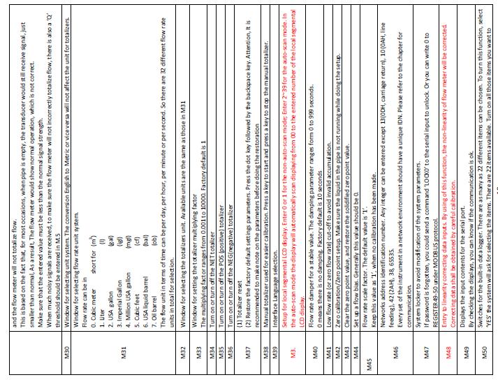
15 3.2 Menu Window Details
16

17

18

19

20

21

22 4. How To 4.1 How to judge if the instrument works properly Enter into M08, if R is displayed on the screen, the instrument is working properly, If 'E' is displayed, the current loop output is over-ranged. Increasing the range setting in M57 will make the 'E' letter disappear. If you do not use current loop output, you may ignore this error. If 'Q' is displayed, the frequency output is over-ranged. Increasing the range setting in M69 will make the 'Q' letter disappear. If you do not use frequency output, you may ignore this error. If an H flashes on that place, there could be poor signal received. Please refer to the chapters on diagnosis. If 'G' is displayed, the flow meter is adjusting system gain. This is normal as far as it does not last long time. If an I is displayed, it means that there is no signal detected. If 'J' is displayed, there is hardware problem. Turn off the power, then, turn on the power again. If the problem remains, refer to Chapter 5 for diagnosis details.
23 4.2 How to judge the liquid flowing direction (1) Make sure that the instrument works properly (2) Check the flow rate for the indication. If the displayed value is POSITIVE, the direction of the flow will be from the A transducers to the B transducers; if the displayed value is NEGATIVE, the direction will be from the B transducers to the A transducers; 4.3 How to change between units systems Use menu window M30 for the selection of unit system in English or Metric system. 4.4 How to select a required flow rate unit Use menu window M31 to select the flow unit first and then the timing unit. 4.5 How to use the totalizer multiplier Use window M33 to select a proper totalizer. Make sure that the totalizer pulse is appropriately speeded. It should not be too fast and neither too slow. A speed of producing a pulse in several seconds or minutes is preferable. If the totalizer multiplier is too small, there can be a loss of accumulation pulse because the output device can output only one pulse in a measurement period (500milliseconds) If the totalizer multiplier is too large, the output pulse will be too fewer for the devices that are connected with the instrument for a quicker response. 4.6 How to open or shut the totalizers Use M34, M35 and M36 to turn on or turn off the POS, NEG, or NET totalizer respectively. 4.7 How to reset the totalizers Use M37 to reset the proper totalizer. 4.8 How to restore the flow meter with default setups Use M37, when the selection message is displayed. Press the dot key first and the message Master Erase will display, then press the backspace key The master erase step will erase all the parameters entered by the user and setup the instrument with default values except instrument factor and network identification number parameter
24 4.9 How to use the damper The damper acts as a filter for a stable reading. If 0 is entered in window M40, that means there is no damping. A bigger number brings a more stable effect. But bigger damper numbers will prevent the instrument from acting quickly. Numbers 0 to 30 are commonly used for the damper value. Default value is 10 seconds How to use the zero-cutoff function The number displayed in window M41 is called the lower flow rate cut-off value. The flow meter will replace these flow rate values that are absolutely less than the low-cutoff value with 0. This means the flow meter will avoid any invalid accumulation when the actual flow is below the zero-cutoff value. Generally the default value is 0.03m/s The low-cutoff value does not affect the flow measurement when the actual flow is absolutely greater than the low-cutoff value How to setup a zero point There exists a Zero Point with certain installation which means the flow meter will display a non-zero value when the flow is absolutely stopped. In this case, setting a zero point with the function in window M42 will bring a more accurate measurement result. Make sure that there is no liquid running inside the pipe, and then run the function in window M42 by pressing the ENT key How to get a scale factor for calibration A scale factor is the ratio between the actual flow rate and the indicated value by the flow meter. It can be determined by calibration with standard flow calibration equipment. You may change the scale factor in menu window M45. The scale factor can be determined by calibration with flow calibration equipment How to use the system locker The system locker provides a means of preventing inadvertent configuration changes or totalizer resets. When the system is locked, menu window browsing can be done without affecting any change, but any modifications are prohibited. The system can be locked without a password or with a 1 to 4 digit password. With a no-password locking, directly press the ENT key in M47 If the password is forgotten, please contact the factory.
25 4.14 How to use 4-20mA current loop output The accuracy of the current loop output is better than 0.1%. It can be configured to different mode, such as 4-20mA mode, 0-20mA etc. Mode selection can be made in menu M55. Refer to the next chapter for details on M55. In order to use the 4-20mA output function, you need not only select the mode to be 4-20mA in M55, but also set the flow rate values which correspond to the minimum current (4mA) and the maximum current (20mA). Enter the two values in M56 and M57. Example A: flow rate range is 0-500m3/h. Just enter 0 in M56 and 500 in M57. Example B: flow rate range is m3/h. If flow direction is not an issue for you, you may select mA mode in M55. Then, enter 500 in M56 and 1000 in M57. If flow direction is an issue, you may select mA mode in M55. This means that the current loop will output 0-4mA when flow rate is negative and 4-20mA when flow rate is positive. Enter -500 in M56 and 1000 in M57. You may need to calibrate and test the current loop output before using it. Just go to menu M58 and do the following: First, connect an ammeter to the current loop output. Press MENU 58, then ENT to enter into menu M58. Use /+ and /- to display "0mA", "4mA", "8mA", "16mA", "20mA" orderly, record the corresponding reading on the ammeter. Calculate the differences between the readings and the selected ones. For instance, when 4mA is selected, the actual output current shown on the ammeter is 4.01mA. Then, the difference is 0.01mA. If the differences are not within tolerance, calibrate the current loop The present current loop output is displayed in Window M59. It changes along with flow rate change How to use the Frequency Output There is a Frequency Output in all TFUF-TT series flow meters. This frequency output signal, which represents the flow rate, is intended to connect with other instruments.
26 The Frequency Output is totally user-configurable. Generally, four parameters should be configured for the setups.enter the lower flow rate value in window M68 and the higher flow rate value in window M69. Enter the frequency range in window M67. For example, assume that the flow rate varies in a range 0m3/h to 3000m3/h, and an output signal is at a maximum frequency of 1000Hz, the minimum of 200Hz is going to be required for other instrumentation. The user should enter 0 in M68 and 3000 in M69, and enter 200 and 1000 in window M67. Please note that the user has to make the selection with OCT setups in window M How to use the Totalizer Pulse Output The totalizer output will produce a pulse output with every unit flow of the totalizer. The totalizer pulse output can only be realized by mapping the pulse output to the OCT or BUZZER hardware devices. For example, assume that the POS totalizer pulse output is needed, and every pulse should represent 0.1cubic meter of liquid flow; the pulse output will be mapped to the internal Buzzer, so that with every 0.1 cubic meter of flow the BUZZER will beep for a while. The following setups should be taken / performed: (1) Select the unit Cubic Meter under window M32. (2) Select the Multiplier as 2. X0.1 under window M33. (3) Select the output option 9. POS INT Pulse under window M77. (INT stands for totalized ) 4.17 How to produce an alarm signal There are 2 types of hardware alarm signals that are available with this instrument. One is the Buzzer, and the other is the OCT output. Both for the Buzzer and OCT output the triggering sources of the event include the following: (1) There is no receiving signal (2) There is poor signal received. (3) The flow meter is not in normal measurement modes. (4) Reverse flow. (5) Overflow occurs at the analogue output by 100% or more (6) Overflow occurs at the frequency output by 120% or more. (7) The flow rate is out of the specified range which is configured in windows M73 and M74 for Alarm #1, and in windows M75 and M76 for Alarm #2.
27 Example A: assume we need the Buzzer to start beeping when the flow meter is not ready in normal measurement. Switch to M77, select item "2. Abnormal Measurement State" Example B: assume we need the Buzzer to start beeping when the flow rate is less than 300 m3/h and greater than 1000m3/h. The following setup steps would be recommended: (1) Enter flow rate lower limit 300 in M73 for #1 alarm, (2) Enter flow rate upper limit 1000 in M74 for #1 alarm, (3) Select item '6. Alarm #1' in M77. Example C: assume we need the OCT output to activate when flow rate exceeds 100~500m3/h and the relay output to activate when flow rate exceeds 600~1000m3/h. The following setup steps would be recommended: (1) Enter flow rate lower limit 100 in M73 (2) Enter flow rate upper limit 500 in M74 (3) Enter flow rate lower limit 600 in M75 (4) Enter flow rate lower limit 1000 in M76 (5) Select item '6. Alarm #1' in M78 (6) Select item '6. Alarm #1' in M How to use the built-in Buzzer The built-in buzzer is user-configurable. It can be used as an alarm. Use M77 for setups How to use the OCT output The OCT output is user-configurable, which can be performed by selecting the proper input source such as pulse output. Use M78 for the setups. Please make sure that the Frequency Output shares the OCT. The OCT output shares pins with the RS-232C interface, and the terminal is at Pin 1 and How to modify the built-in calendar No modification on the built-in calendar will be needed in most cases. The calendar runs on insignificant amount of power supply. Modification will be required only in such cases as when the battery is totally consumed, or when the changing of the battery takes a long time. Press the ENT key under M60 for Modification. Use the dot key to skip over these digits that need no modification.
28 4.21 How to view the Date Totalizers Use M82 to view the date totalizers that are comprised of a daily totalizer, a monthly totalizer and a yearly totalizer How to use the Working Timer Use the working timer to check the time that has passed with a certain kind of operation. For example, use it as a timer to show how long a fully-charged battery will last. Under M72, press ENT key and then select YES to reset the timer How to use the manual totalizer Use M38 for the manual totalizer. Press ENT key to start and stop the totalizer How to know how long the battery will last Use M07 to check how long the battery will last. Also please refer to How to check the ESN and other minor details Every set of the BSUF-TTCL flow meter utilizes a unique ESN to identify the meter. The ESN is an 8-digit number that provides the information of version and manufacturing date. The user can also employ the ESN for instrumentation management. The ESN is displayed in window M61. Other details about the instrument are the total working hours displayed in window M+1, and the total poweron times displayed in window M How to use the data logger for scheduled output Use menu window 51 to setup the time of scheduled output, including start time, time interval and how many times of output. Then use menu window 50 to turn on data logger and select the items you want to output How to output analogue voltage signal Parallel a 250 resistance to the terminal of the Current loop output (No.21, 22), then you can change the 4-20mA output to analogue voltage output.
29 4.28 How to adjust the LCD display You may use menu window 70 to setup the LCD display backlight and menu window 71to adjust contrast it How to use RS232/RS485? Use menu window 62 to set up RS232/RS485. All the devices connected with flow meter should have matchedserial configuration. The following parameters can be configured: Baud rate (300 to bps), parity, data bits (always is 8), stop bits (1) How to use automatic amending function for offline compensation Use menu window 83 turn on or turn off this function. When the function is enabled, the flow meter will estimate the average flow uncounted (or lost ) during the offline session and add the result to the totalizer. This function is not recommended. The user should manage to avoid the offline time to keep precision of the measurement result How to use batch controller Please do the following to use the batch controller: 1) Go to menu window 80 to select the trig signal. 2) Go to menu window 78 (OCT output) or 79 (relay output), select 8 Batch Control. 3) Use menu window 81 to set the flow batch value (dose) How to adjust the analogue output We have adjusted every set of meter before delivery. Unless you find the current indicated in menu 58 is different with the actual current output, please do not do this operation. Press keys MENU /- 0, use the password to enter the window. Notice: the window will close after power off and the password will become invalid then. Press keys MENU /- 1, to adjust the 4mA current output: use precision ammeter to measure the output current, at the same time, use /+ /- to adjust the digital on the flow meter until the ammeter indicate Then press ENT to enter the window of adjusting the 20mA output. When finished adjusting, you have to use menu window 26 to store the result into the flash memory, so that it will be solidified and will not be lost even the reserve battery removed How to solidify the parameters There are three kinds of parameters for the new generation TFUF-TTCL
30 1) Current parameters, the parameters are stored in the RAM. They will be lost when one cut the power or remove the reserve battery. 2) Solidified parameters, you may use menu window 26 to store the parameters in the Flash memory and they will not be lost even power off. This menu window is also a switch for the parameters in flash memory to be loaded when power is turned on. The default option is that the parameters will be loaded. So if the parameters are very stable, you may need this option. 3) User frequently-used parameters, you can use menu window 27 to store or restore from the internal Flash memory, as many as 9 different pipe parameter configurations How to enter the parameters of user-type-transducer If a user-type-transducer is selected in menu window 23, you need proceed to enter additional 4 usertypewedge parameters that describe the user transducers. If the PI-type transducer is selected, you need enter additional 4 PI-type transducer parameters that describe the PI-type transducers How to use the circular display function When entering menu window 95, the circular display function will be started automatically. The following windows will be displayed one by one, each window will stay for 8 seconds: M95>>M00>>M01>>M02>>M02>> M03>>M04>>M05>>M06>>M07>>M08>>M90>>M91>>M92>> M93>> M94>>M95. This function allows the user to visit all the important information without any manual action. To stop this function, simply press a key. Or switch to a window other than M How to enter into the linearity correcting? How to enter into the data? When the product leaved the factory, the function is closed. The menu can realize almost 12 parts linearity correcting. The user can choose from two points to twelve points to execute the linearity correcting according to user actual condition. In order to explain the usage method of the menu, we suppose that we get the following table data through calibration the meter. In order to revised the flow exceed the scope of the above table, without mutations of correction factor, we add two points on the basis of the above five points, (0 m3/h, 1.0) and ( m3/h, 1.0). (0 m3/h, 1.0) is called the minimum flow of the amendment point, this set of data is used to facilitate to generated a appropriate correction factor when Instrumented show flow under 1.02 m3/h. ( m3/h, 1.0) is called the maximum flow of the amendment point, this set of data is used to facilitate to generated a appropriate correction factor when Instrumented show flow above m3/h. So that we get the following data sets from small to large.
31 The total is seven sets of data. The next step is to put seven sets of data entered into the Instrument. Pay attention to the input order in accordance with from small to large. To enter the menu M48, then input the data set number 7, to be followed in the above seven sets of data, we revised the setup of a multi-segment linearity correcting. If you need to cancel linearity correcting, simply enter 0 in the menu M48. Decommissioned linearity correcting, you just need to enter in the menu M48 data points (in this case, is 7 ). Noted: before the calibration of the instrument, you must first close the linearity correcting function. If under the condition that the linearity correcting function has not closed, the calibration data sets arising from the amendment must be dealing with the reverse curve of the data following the original amendment, then input to the Instrument. Reverse amendment is very complicated, and should be avoided How to save / restore frequently-used pipe parameters You can use menu window 27 to store or restore from the internal Flash memory, as many as 9 different pipe parameter configurations. 5. Troubleshooting 5.1 Power-on Error Displays and Counter-Measures The TFUF-TTCL ultrasonic flow meter provides an automatic power-on diagnosis for the hardware problems. When any message (with the power on) in the following table displays, counter-measures should be taken.
32 5.2 Error Code and Counter-Measures The TFUF-TTCL ultrasonic flow meter will show Error Code in the lower right corner with a single letter like I, Retc. on menu windows M00, M01, M02, M03, M90 and M08. When any abnormal Error Code shows, countermeasures should be taken. 5.3 Other Problems and Solutions 1. When the actual flow inside the pipe is not standstill, but the instrument displays for the flow rate, and R displaying signal strength and the signal quality Q (value) has a satisfactory value? The problems are likely caused by the user who has used the Set Zero function on this non-standstill flowing pipe. To solve this problem, use the Reset Zero function on menu window M The displayed flow rate is much lower or much higher than the actual flow rate in the pipe under normal working conditions. (1) There is probably an offset value wrongly entered by the user in M44. Enter 0 in M44.
 There is a Zero Point.")

33 (2) Problem with transducer installation. (3) There is a Zero Point. Try to zero the instrument by using M42 and make sure that the flow inside the pipe should be standstill.

34
Handheld Ultrasonic Flow meter User Manual
 Handheld Ultrasonic Flow meter User Manual LONGRUN INDUSTRIAL INSTRUMENT CO.,LTD Contents 1. Introduction... 1 1.1 Preface... 1 1.2 Main Features... 1 1.3 Principle of Measurement... 2 1.4 Packing List
TDS-100H Handheld Ultrasonic Flowmeter. User manual
 TDS-100H Handheld Ultrasonic Flowmeter TDS-100H Handheld Ultrasonic Flowmeter User manual - 2 - TDS-100H Handheld Ultrasonic Flowmeter Contents 1. Introduction... 1 1.1 Preface... 1 1.2 Main Features...
Handheld Ultrasonic Flow Meter. Series TFM1100-P. User Manual
 www.aktek.com.tr Handheld Ultrasonic Flow Meter Series TFM1100-P User Manual Contents 1. Introduction 4 1.1 Preface 4 1.2 Main Features 4 1.3 Principle of Measurement 5 1.4 Packing List (Standard Configuration)
TDS-100H Handheld Ultrasonic Flowmeter. User manual
 TDS-100H Handheld Ultrasonic Flowmeter User manual - 2 - Contents 1. Introduction... 1 1.1 Preface... 1 1.2 Main Features... 1 1.3 Principle of Measurement... 2 1.4 Packing List (Standard Configuration)...
Safsonic P. Handheld Ultrasonic Flow meter. User Manual
 01 Safsonic P Handheld Ultrasonic Flow meter User Manual 05 Safmag House P.O.Box 17143 Int Tel.: +27(0)312060630 498 Sydney Road Congella SA Tel.: 086 110 6028 Congella South Africa, 4013 enquiries@flowmetrix.co.za
Hand Held Ultrasonic Flow Meter
 Hand Held Ultrasonic Flow Meter CONTENTS 1. INTRODUCTION... 3 1.1 PREFACE... 3 1.2 FEATURES... 3 1.3 FLOW MEASUREMENT PRINCIPLE... 3 1.4 PART IDENTIFICATION... 5 1.5 APPLICATIONS... 7 1.6 DATA INTEGRITY
FMU-2000F PLEASE READ THIS MANUAL CAREFULLY BEFORE OPERATION
 Operation Manual Ultrasonic Flow Meter FMU-2000F PLEASE READ THIS MANUAL CAREFULLY BEFORE OPERATION 3, Hagavish st. Israel 58817 Tel: 972 3 5595252, Fax: 972 3 5594529 mrc@mrclab.com MRC.2.16 1. Introduction
PROSOL PCS Ultrasonic Flowmeter Installation and User Guide V
 Index PROSOL PCS Ultrasonic Flowmeter Installation and User Guide V 18.4.1 1.0 Component Identification 1.1 Meter Specifications 2.0 Preparation for Installation 3.0 Installation / Set up 3.1 Menu Navigation
Model R7900. Instruction Manual. Ultrasonic Thickness Gauge. reedinstruments. www. com
 Model R7900 Ultrasonic Thickness Gauge Instruction Manual reedinstruments com Table of Contents Features... 3 Specifications...4-5 Instrument Description... 6 Operating Instructions...7-10 Adjusting the
Innova-Sonic Model 210i Instruction Manual
 Innova-Sonic Model 210 Portable Innova-Sonic Model 210i Instruction Manual Version IM-210i, Rev. A (1.0.0), March 2011 Innova-Sonic Model 210 Portable GLOBAL SUPPORT LOCATIONS: WE ARE HERE TO HELP! CORPORATE
TUF Ultrasonic Flow Meter. One. Overview V =
 One. Overview TUF Ultrasonic Flow Meter series ultrasonic flow meter is designed on the theory of low voltage and time difference of multi pulse. It can be used to measure transmission time of ultrasound
Model Sono-Trak Transit Time
 Model Sono-Trak Transit Time Ultrasonic Flow Meter Engineered for performance excellence, the Sono-Trak Transit Time ultrasonic meter combines non-invasive, bi-directional measurement with advanced ultrasonic
TEK-CLAMP 1200A Ultrasonic Clamp-On Flowmeter
 TEK-CLAMP 1200A Ultrasonic Clamp-On Flowmeter Instruction Manual Document Number: IM-1200A NOTICE Read this manual before working with the product. For personal and system safety, and for optimum product
Instruction Manual ABM HART Gateway Software. Instruction Manual Revision A.1
 Instruction Manual ABM HART Gateway Software Instruction Manual Revision A.1 Table of Contents Section 1: Getting Started... 3 1.1 Setup Procedure... 3 1.2 Quick Setup Guide for Ultrasonic Sensors... 11
SGM-100H Transit time ultrasonic flowmeter
 SGM-100H Transit time ultrasonic flowmeter 825B108B Features Rechargable battery: 10h lasting Battery charger: 100 253Vac Display: alphanumeric 4x16 digits Keypad: 16+2 pushing buttons Displayed data:
BE6000 Series Ultrasonic Flow Meter
 BE6000 Series Ultrasonic Flow Meter 2 Flomotion Systems, Inc. ~ FlomotionSystems.com Installation and Operation Manual BE6000 Series Ultrasonic Transit-Time Flow Meter JANUARY 2012 V18 Flomotion Systems,
ULTRASONIC FLOW METER FT101
 Introduction F t101 is a wall-mount, clamp- on type ultrasonic flowmeter which use the transfer time technology. Clamp on type ultrasonic flowmeter is easy to install and no need to cut off the pipe, that
Handheld Ultrasonic Flowmeter
 Handheld Ultrasonic Flowmeter Features High Accuracy measuring A c c u r a c y : ±1 %, l i n e a r i t y : 0. 5 %, r e p e a t a b i l i t y : 0. 2 % Wi d e m e a s u r i n g r a n g e Several types transducer
Ultrasonic Flowmeter. Manual
 Ultrasonic Flowmeter FUM-1000 Series Manual #105 Business Incubator Center Hanyang Univ., Sa 3-dong, Sangrok-gu, Ansan-si, Gyeonggi_do, Korea Tel: +82-31-415-9992,3 Fax: +82-31-415-9994 http: // www.flovel.co.kr
FLOW SWITCH 600 Series Velocity Flow Sensor. Instruction Manual
 SWITCH 600 Series Velocity Flow Sensor Instruction Manual Ultrasonic Velocity Sensor using Doppler Technology Model: FS-600 Manual Release Date: November, 2009 ECHO Process Instrumentation, Inc. CONTENTS
MB1013, MB1023, MB1033, MB1043
 HRLV-MaxSonar - EZ Series HRLV-MaxSonar - EZ Series High Resolution, Low Voltage Ultra Sonic Range Finder MB1003, MB1013, MB1023, MB1033, MB1043 The HRLV-MaxSonar-EZ sensor line is the most cost-effective
Applications Features
 GE Measurement & Control TransPort PT878 Panametrics Portable Liquid Ultrasonic Flowmeter Applications The TransPort PT878 portable liquid flowmeter is a complete portable ultrasonic flow metering system
CJLC-9007 Temperature and humidity control meter Operation Instruction
 CJLC-9007 Temperature and humidity control meter Operation Instruction I. Survey Thanks for your using CJLC-9007 control meter. This handbook provides users for installing, running, operating, parameter-setting,
ULTRASONlC FlOWMETER SAMPLE BOOK. TYPE:LRF-3300S Concentrating on Flow Measurement
 ULTRASONlC FlOWMETER SAMPLE BOOK TYPE:LRF-3300S Concentrating on Flow Measurement Introduction LRF-3300S is a wall-mount, clamp- on type ultrasonic flowmeter which use the transfer time technology. Clamp
Technical Specification FLUXUS ADM 8127B
 FLUXUS ADM 8127B Liquid Ultrasonic Flowmeter for Permanent Installation in Hazardous Areas in the Mining Environment FLUXUS ADM 8127B is especially designed for the stationary use in explosive atmosphere
Wall Mounted Ultrasonic Flowmeter USER GUIDE
 Wall Mounted Ultrasonic Flowmeter USER GUIDE 1 of 21 1. O U T LI N E.. 3 1.1 Principle of Measurement. 4 2. S t ar t i ng M eas ur em ent 5 2.1 Wall-Mounted, Fixed Style Ultrasonic Flow Meter. 6 3. D i
S L n u. M e. E n te r. Transmitter: Flow range: 0 ~ ±40ft/s (0 ~ ±12m/s) Accuracy: ±1.0% Repeatability: 0.3% Outputs: OCT, KHz
 Accuracy: ±1.0% Repeatability: 0.3% Outputs: OCT, KHz") S L 1 16 8 7 8 9 M e n u 4 5 6 1 2 3 E n te r 0 Transmitter: Flow range: 0 ~ ±40ft/s (0 ~ ±12m/s) Accuracy: ±1.0% Repeatability: 0.3% Outputs: OCT, 0-9999 KHz Sl 1168 Ultrasonic Flowmeter Brochure Series1168
S L 1 16 8 7 8 9 M e n u 4 5 6 1 2 3 E n te r 0 Transmitter: Flow range: 0 ~ ±40ft/s (0 ~ ±12m/s) Accuracy: ±1.0% Repeatability: 0.3% Outputs: OCT, 0-9999 KHz Sl 1168 Ultrasonic Flowmeter Brochure Series1168
Flow Technologies Overview. For internal use only / Siemens AG All Rights Reserved.
 Flow Technologies Overview Mag Flow MAGFLO Program Siemens offers a comprehensive selection of electromagnetic flow meters Water & waste water Chemical Food & beverage Mining Aggregates Cement Pharmaceutical
CONNECT SYSTEMS INCORPORATED 5321 Derry Ave., Suite B Agoura Hills, CA FLEX SERIES UNIVERSAL CONTROLLER
 CONNECT SYSTEMS INCORPORATED 5321 Derry Ave., Suite B Agoura Hills, CA 91301 Phone (805) 642-7184 Fax (805) 642-7271 FLEX SERIES UNIVERSAL CONTROLLER FLEX IIIA CTCSS COMMUNITY TONE PANEL User s Instruction
USER MANUAL MODEL USFT-CS ULTRASONIC FLOW TRANSMITTER. Rev04009 USER MANUAL DEI MODEL USFT-CS
 Rev04009 USER MANUAL DEI MODEL USFT-CS USER MANUAL MODEL USFT-CS ULTRASONIC FLOW TRANSMITTER The Model USFT-CS is an ultrasonic transit time flow meter designed to accurately and reliably report the flow
Technical Specifications
 Technical Specifications EnduroFlow TM Series EF11 Solar Powered Ultrasonic Flowmeter For accurate Flow Measurement FEATURES AND BENEFITS Solar powered with a rugged 20Watts solar panel Built in rechargeable
Digital Electronic Thermostat With RF
 RT300RF Manual Altech 005_89 06/05/2014 08:56 Page 1 Digital Electronic Thermostat With RF Instruction Manual Model No ALTHC015 RT300RF Manual Altech 005_89 06/05/2014 08:56 Page 2 2 ALTHC015 INSTRUCTION
OVEN INDUSTRIES, INC. Model 5C7-362
 OVEN INDUSTRIES, INC. OPERATING MANUAL Model 5C7-362 THERMOELECTRIC MODULE TEMPERATURE CONTROLLER TABLE OF CONTENTS Features... 1 Description... 2 Block Diagram... 3 RS232 Communications Connections...
Brunata Optuna H Ultrasonic energy meter Type 775 Installation Guide Edition 1.2
 Ultrasonic energy meter Type 775 Installation Guide Edition 1.2 UK-QB101575 / 29.05.2012 Brunata a/s is a Danish owned company. We have more than 90 years of experience within developing and producing
Four Carrier Signal Generator Operation Manual
 ACE 5400 Four Carrier Signal Generator Operation Manual Table of Contents 1. Features...2 1.1. Specifications...3 1.2. Connections...3 1.3. Controls and Connections...4 1.4. Keypad...4 2. Operating Modes...5
5096 FIRMWARE ENHANCEMENTS
 Document Number A100745 Version No.: 4.4.1 Effective Date: January 30, 2006 Initial Release: September 19, 2005 1. Fixed display of logged memory date and time broken in version 4.3. 2. Allow time samples
ma/bcd Converter Model MFC-201 ma/bcd The MFC-201 ma/bcd Converter is a device designed to convert a DC current signal into BCD (8421) signals.
 signals.") 1 Definition ma/bcd Converter Model MFC-201 ma/bcd The MFC-201 ma/bcd Converter is a device designed to convert a DC current signal into BCD (8421) signals. 2 Operating Principle An electronic circuit
1 Definition ma/bcd Converter Model MFC-201 ma/bcd The MFC-201 ma/bcd Converter is a device designed to convert a DC current signal into BCD (8421) signals. 2 Operating Principle An electronic circuit
INSTRUCTION MANUAL FOR ULTRASONIC/MICROWAVE SENSORS
 INSTRUCTION MANUAL FOR ULTRASONIC/MICROWAVE SENSORS 1)Install PROBE_GatewayPC Software on PC.Remove previous installation. In Windows Control Panel go to the Programs and Features, select Probe_GatewayPC_Net
8000 SERIES PRECISION MULTIMETER VERIFICATION AND ADJUSTMENT GUIDE
 8000 SERIES PRECISION MULTIMETER VERIFICATION AND ADJUSTMENT GUIDE TRANSMILLE LTD. Version 1.1 : Apr 2015 TABLE OF CONTENTS PREPARING FOR CALIBRATION... 4 INTRODUCTION... 4 CALIBRATION INTERVAL SELECTION...
M 140i. Multifunction Calibrator. Operation Manual
 M 140i Multifunction Calibrator Operation Manual M-140i Multifunction Calibrator MEATEST, s.r.o. 2 Operation Manual v35 MEATEST, s.r.o. M-140i Multifunction Calibrator Content Operation Manual... 1 Basic
UltraFlo UFDD ULTRASONIC CLAMP-ON FLOW METER
 UltraFlo UFDD ULTRASONIC CLAMP-ON FLOW METER DESCRIPTION The UltraFlo UFDD Clamp-On Ultrasonic Flow Meter is the ideal flow meter with accurate, easy-to-use, easy-to-install digital doppler technology.
Ultrasonic Flowmeter Instruction Manual. Model: LRF-3000H. LRF-3000H Handheld Ultrasonic Flowmeter. Revision 1.1. Update Record. Date Nov.
 Ultrasonic Flowmeter Instruction Manual Model: LRF-3000H Update Record Revision 1.1 Date Nov. 2010 Version: 1.1 Page 0 of 42 Notice LRF-3000H Handheld Ultrasonic Flowmeter Thank you for choosing the LRF-3000H
MHPS MHPS. Modular pressure transmitter. Technical documentation. Table of content. Characteristics - applications - technical data
 Technical documentation Table of content Page 2: Page 3: Page 4: Page 5: Page 6: Page 7: Page 8: Characteristics - applications - technical data Technical data - input quantity - output quantity Electrical
Temperature Controller model MFC-301/T-Dry. Version for Dry Transformers and Motors. Technical Manual. Licht
 Temperature Controller model MFC-301/T-Dry Version for Dry Transformers and Motors Technical Manual Licht Contents 1 Introduction 2 2 Operating principle 3 2.1 General principle 3 2.2 RTD operation 3 3
JPQ2 PULSE ACCUMULATOR
 INSTRUCTION MANUAL PULSE ACCUMULATOR (field-programmable; built-in excitation) MODEL JPQ JPQ BEFORE USE... Thank you for choosing M-System. Before use, check the contents of the package you received as
MK372/Ultrasonic Sensor System. Installation & Setting up Instructions. Comprising. MK372 Indicator/Controller Ultrasonic Transmitter
 MK372/Ultrasonic Sensor System Installation & Setting up Instructions Comprising MK372 Indicator/Controller Ultrasonic Transmitter 1 Contents page Page 1.0 Overview 3 2.0 General Specification MK372 4
Precision Range Sensing Free run operation uses a 2Hz filter, with. Stable and reliable range readings and
 HRLV-MaxSonar - EZ Series HRLV-MaxSonar - EZ Series High Resolution, Precision, Low Voltage Ultrasonic Range Finder MB1003, MB1013, MB1023, MB1033, MB10436 The HRLV-MaxSonar-EZ sensor line is the most
MT3500 Hand-Held Engine Analyzer Safety Operation Regulations
 MT3500 Hand-Held Engine Analyzer Safety Operation Regulations - 1 - Chapter One Introduction A. Notice of Usage: MT3500 Hand-Held Engine Analyzer must be operated by trained professionals, who must know
FRUIT BONUS 2 nd Generation 2004 AMCOE INC.
 PIN PARTS SIDE SOLDER SIDE PIN 1 VIDEO RED VIDEO GREEN 1 2 VIDEO BLUE VIDEO SYNC 2 3 SPEAKER + SPEAKER - 3 4 EXTRA - 4 5 EXTRA - STOP 2 EXTRA - ALL STOP 5 6 EXTRA - STOP 3 6 7 TICKET OUT BUTTON - panel
Ultrasonic transducers being installed in the 2.4m (96 ) aqueduct at Watchgate WTW, Cumbria, UK.
 aqueduct at Watchgate WTW, Cumbria, UK.") Ultrasonic transducers being installed in the 2.4m (96 ) aqueduct at Watchgate WTW, Cumbria, UK. A Sarasota 2000 Ultrasonic flowmeter, installed at Watchgate water treatment works in Cumbria on the 2.4m
Ultrasonic transducers being installed in the 2.4m (96 ) aqueduct at Watchgate WTW, Cumbria, UK. A Sarasota 2000 Ultrasonic flowmeter, installed at Watchgate water treatment works in Cumbria on the 2.4m
GFL-1000 User Manual Ground Fault Locator
 GFL-Series User Manual V1.1 GFL-1000 User Manual Ground Fault Locator Contents Contents... 1 1 Declaration of Conformity... 3 2 Introduction... 3 3 Equipment Information... 3 3.1 Safety Precautions...
TEK-TROL HART GATEWAY SOFTWARE. Operating Instruction Manual.
 TEK-TROL HART GATEWAY SOFTWARE Operating Instruction Manual www.tek-trol.com Table of Contents 1 Getting Started... 2 1.1 Setup Procedure... 2 1.2 Quick Setup Guide for Radar Sensors... 10 2 Level device
Technical specification FLUXUS F401 H2O
 Technical specification Ultrasonic flowmeter for water Portable, very robust and easy-to-use ultrasonic flowmeter for the water and wastewater industry Features Very high bi-directional measuring accuracy
DigitalFlow XMT868i. Panametrics Liquid Flow Ultrasonic Transmitter. GE Measurement & Control. Applications. Features
 GE Measurement & Control DigitalFlow XMT868i Panametrics Liquid Flow Ultrasonic Transmitter The DigitalFlow XMT868i liquid flow transmitter is a complete ultrasonic flow metering system for measurement
INSTRUCTION MANUAL. Power Factor Controller - 12 steps Model A12 NOKIAN CAPACITORS. Power Factor Controller A12
 INSTRUCTION MANUAL Power Factor Controller - 12 steps Model A12 NOKIAN CAPACITORS Power Factor Controller A12 1. CONTENTS 1. CONTENTS 1 2. FEATURES 2 3. INSTALLATION, CONNECTION AND APPLYING POWER 2 4.
INSTRUCTION MANUAL Redox sensor M 1322 C
 INSTRUCTION MANUAL Redox sensor M 1322 C From version 2.01 2013 Controlmatik ABW d.o.o. 2 1. General... 7 1.1 Assembly... 8 1.2 Storage of Redox probes... 9 1.3 Connection to the electrical power supply...
Electromagnetic Flowmeter Comet F
 Electromagnetic Flowmeter Comet F - Exact measurements - Comfortable calibration with PC - No setup elements - No pressure loss - Periodic cleaning of electrodes - Data backup during power failure - Communication
1: Introduction : Caution : Tips for Reading this Manual : Preface : System Highlights : Receiver
 1: Introduction....1 1 2: Caution.... 2 2 3: Tips for Reading this Manual....3 3 4: Preface....4 4 5: System Highlights....6 6 6: Receiver..7 7 6.1: Specifications......7 7 6.2: Receiver Operation... 7
VersaFlow Ultrasonic clamp-on Flowmeter Technical Datasheet. Specification. Applications. Highlights. Industries. 34-VF September 2009
 VersaFlow Ultrasonic clamp-on Flowmeter Technical Datasheet 34-VF-03-14 September 2009 Specification Clamp-on technology HONEYWELL S VERSAFLOW stands for continuity and long term reliability. Flow measurement
MaxBotix Inc. Copyright MaxBotix Incorporated Patent 7,679,996. Close Range Operation. Warning: Personal Safety Applications
 HRXL-MaxSonar - WR Series High Resolution, Precision, IP67 Weather Resistant, Ultrasonic Range Finder MB7360, MB7363, MB7366, MB7367, MB7369, MB7380, MB7383, MB7386, MB7387, MB7389 8 The HRXL-MaxSonar-WR
EN-2018 MAGNETIC FLOW METERS
 EN-2018 MAGNETIC FLOW METERS www.meatest.com 1 MEASURING PRINCIPLE Having no moving or mechanical parts in the flow profile electromagnetic flow meters cause no pressure drop, are virtually maintenance
WIRELESS Energy Monitor - Smart Meter
 Energy saving made simple MONITOR CONTROL SAVE WIRELESS Energy Monitor - Smart Meter Monitors your electricity use and cost in real time Instruction Manual EW4500 IMPORTANT Please retain your Instruction
FoxRex RigExpert. Made in Ukraine. User s manual. ARDF Receiver 3.5MHz
 FoxRex 3500 ARDF Receiver 3.5MHz RigExpert Made in Ukraine User s manual . Table of contents Introduction Specifications Getting started Charging the battery Installing the whip antenna Switching the receiver
Mag 3/6 System. Manual.
 Mag 3/6 System Manual www.undergroundmagnetics.com 1: Introduction....1 1 2: Caution.... 2 2 3: FCC Compliance Statement.. 3 4: Tips for Reading this Manual....3 4 5: Preface....4 5 6: System Highlights....6
Acoustic Velocity Independent Ultrasonic Flow-Meter
 flotek.g 2017- Innovative Solutions in Flow Measurement and Control - Oil, Water and Gas August 28-30, 2017, FCRI, Palakkad, Kerala, India Acoustic Velocity Independent Ultrasonic Flow-Meter ABSTRACT Shalini
HP 33120A Function Generator / Arbitrary Waveform Generator
 Note: Unless otherwise indicated, this manual applies to all Serial Numbers. The HP 33120A is a high-performance 15 MHz synthesized function generator with built-in arbitrary waveform capability. Its combination
UCM-60 / UCM-60DL Technical Description. Revision 1.10
 UCM-60 / UCM-60DL Technical Description Revision 1.10 Table of contents 1 Document Scope... 1 1.1 Parameters... 1 1.2 Configurations... 1 1.3 Sensors... 1 1.4 Microprocessor... 2 1.5 Communication... 2
Flow Switch - 2 programmable thresholds. Stand Alone (Battery) - Battery powered, - 2 totalizers display, - Local flow display,
 - Battery powered, - 2 totalizers display, - Local flow display,") DN 15 - DN 50; PN Advantages / Benefits Easy System integration by Easy LINK provides low cost of ownership Easy commissioning due to multi-language, menu-guided operation TEACH-IN: automatic calibration
DN 15 - DN 50; PN Advantages / Benefits Easy System integration by Easy LINK provides low cost of ownership Easy commissioning due to multi-language, menu-guided operation TEACH-IN: automatic calibration
TIGER HOOK 2004 AMCOE INC.
 TIGER HOOK 2004 AMCOE INC. PIN PARTS SIDE SOLDER SIDE PIN 1 VIDEO RED VIDEO GREEN 1 2 VIDEO BLUE VIDEO SYNC 2 3 SPEAKER + SPEAKER - 3 4 EXTRA - 4 5 EXTRA - STOP 2 EXTRA - ALL STOP 5 6 EXTRA - STOP 3 6
KOBOLD EchoKing NEO-5003 Series Ultrasonic Level Transmitter User Instructions KOB
 KOBOLD EchoKing NEO-5003 Series Ultrasonic Level Transmitter User Instructions KOB KOBOLD Instruments Inc. 1801 Parkway View Drive Pittsburgh PA 15205 Phone (412) 788-2830 Fax (412)-788-4890 Manual-NEO_5003-4_1-17
English. Money Counter. Coin and banknote counter. DEUTsCH. Manual
 ITALIANO ESPAÑOL FRANçAIS NEDERLANDS English Money Counter DEUTsCH Coin and banknote counter Manual Money Counter for Coins and Banknotes Introduction Thank you for choosing the Money Counter series. The
7 Function description 7.1 Digital filter Alarm output
 User manual KH300 1 Preface 1.1 Preface ---------------------------------------1 1.2 Parts list---------------------------------------2 1.3 Notice------------------------------------------2 2 General 2.1
Mate Serial Communications Guide This guide is only relevant to Mate Code Revs. of 4.00 and greater
 Mate Serial Communications Guide This guide is only relevant to Mate Code Revs. of 4.00 and greater For additional information contact matedev@outbackpower.com Page 1 of 20 Revision History Revision 2.0:
Bulk Flow Meter LB 442 CONTACTLESS MEASUREMENT
 Bulk Flow Meter LB 442 CONTACTLESS MEASUREMENT Mass flow determination using the LB 442 Versatile uses Contactless mass flow determination of solid matter on continuous conveyor systems Conveyor belts
AE-250DS Automatic Wave Soldering Machine User s Manual
 AE-250DS Automatic Wave Soldering Machine User s Manual Omxie/SMTmax Corp. www.smtmax.com Copyright 2006 1 P a g e Index of Content 1. Specifications 2. Power Supply 3. Operations 4. Maintenance 5. Warnings
Operator Manual 1.4 FRACSIM MINI
 FracSim Meters FracSim Meters was founded with the intention of providing specifically designed tools for the well service industry. Our goal is to provide quality tools with a robust design to meet the
SITRANS F flowmeters. SITRANS F System information MAGFLO electromagnetic flowmeters 4/9
 Overview MAGFLO family MAGFLO electromagnetic are designed for measuring the flow of electrically conductive mediums. The patented MAGFLO Verificator guarantees accurate measurement and simple verification.
FastLink TM. Network. Operation and Installation Manual
 FastLink TM Network Operation and Installation Manual C6570 C6571 C6571S C6572 C6572S C6573S Store and Forward Controller Network Store and Forward Controller Service Store and Forward Controller Network
Table Of Contents Overview of the operating buttons... 4 The functions of the datalogger... 5 How to start logging from the default settings...
 Table Of Contents 1. Overview of the operating buttons... 4 2. The functions of the datalogger... 5 2.1 LOG... 5 2.2 METER... 5 2.3 REVIEW... 5 2.4 TIME / date... 5 2.5 START time / date... 5 2.6 INT log
DigitalFlow TM CTF878
 DigitalFlow TM CTF878 Panametrics Correlation Tag Clamp-On Gas Ultrasonic Flow Meter Applications The DigitalFlow CTF878 clamp-on gas fl ow meter is a complete ultrasonic fl ow metering system for the
Contents. Overview Introduction...3 Capabilities...3 Operating Instructions Installation...4 Settings... 5
 User s Manual Contents Overview................................................................. 3 Introduction..............................................................3 Capabilities...............................................................3
Technical description of the fuel tank sensor "Escort TD-500"
 Technical description of the fuel tank sensor "Escort TD-500" Kazan, 2016 1 Table of contents 1. General info..3 2. Technical characteristic.. 3 3. Operating mode. 3 3.1. Mode RS-485 3 3.2. Frequency mode
Programmable Control Introduction
 Programmable Control Introduction By the end of this unit you should be able to: Give examples of where microcontrollers are used Recognise the symbols for different processes in a flowchart Construct
The LEBOW 7554 Operator's Manual 7.2
 The LEBOW 7554 Operator's Manual 7.2 This manual covers operating version 7.2 of the LEBOW 7554. 11 February 1999 Lebow Products Inc Lebow Products Inc 1728 Maplelawn Rd Troy, MI 48084 1 (800) 803-1164
BATCHMATE 1500 Batch Control Computer Technical Bulletin
 TS-5(C) BATCHMATE 5 Batch Control Computer Technical Bulletin DESCRIPTION The BATCHMATE features an 8 digit.55-in. alphanumeric LED display. The pulse input model will accept up to 2, pulses per second
The keypad is used to set the flowmeter. The function of the keys are as follows: This key selects the figures to be changed.
 7. 7.1 Keypad and display layout Keypad The keypad is used to set the flowmeter. The function of the keys are as follows: TOP UP KEY FORWARD KEY BACKWARD KEY CHANGE KEY SELECT KEY LOCK/UNLOCK KEY This
Operating instructions Electronic level sensor LK / / 2008
 Operating instructions Electronic level sensor LK31 UK 704046 / 00 01 / 2008 Contents Safety instructions...2 Menu structure...3 Controls and indicating elements...4 Function and features...5 Functional
12912 Farnham Avenue White Bear Lake, Minnesota WILSON WHEEL OPERATOR S MANUAL. for Amada Thick Turret Punch Presses
 12912 Farnham Avenue White Bear Lake, Minnesota 55110 WILSON WHEEL OPERATOR S MANUAL for Amada Thick Turret Punch Presses Rolling Shear Rolling Rib Rolling Offset Rolling Pincher Revised: September 20,
DISCO DICING SAW SOP. April 2014 INTRODUCTION
 DISCO DICING SAW SOP April 2014 INTRODUCTION The DISCO Dicing saw is an essential piece of equipment that allows cleanroom users to divide up their processed wafers into individual chips. The dicing saw
Conductivity +/ 2% 1 or 2 point remotely through PLC or directly on board. Any two lead Conductivity probe (K 0.01, K 0.1, K 1.
 V 2.0 Revised 1/16/17 Conductivity IXIAN Transmitter Reads Range Accuracy Calibration Supported probes Temp probe Conductivity 0.07µS 100,000µS +/ 2% 1 or 2 point remotely through PLC or directly on board
Proximity-Sensor Counter Installation Instruction Model: MRC-PRO
 Proximity-Sensor Counter Installation Instruction Model: MRC-PRO NYS DOT Approval SYSDYNE CORP. 1055 Summer St. 1 st Floor Stamford, CT 06905 Tel: (203)327-3649 Fax: (203)325-3600 Contents: Introduction...
HTTF Transit Time Ultrasonic Flow Meter
 Transit Time Ultrasonic Flow Meter Reduced material costs: clamp-on sensor eliminates the need for in-line flanges, pipe fittings, strainers, and filters Reduced installation time: the may be installed
E l e c t r o m a g n e t i c f l o w m e t e r s
 E l e c t r o m a g n e t i c f l o w m e t e r s P r o v e n A N D R e l i a b l e F l o w M e a s u r e m e n t 2 MJK MagFlux flow meters combine high accuracy, stability and low maintenance. Without
Touch Probe Cycles itnc 530
 Touch Probe Cycles itnc 530 NC Software 340 420-xx 340 421-xx User s Manual English (en) 4/2002 TNC Models, Software and Features This manual describes functions and features provided by the TNCs as of
Efcon Water. Installation & User Manual Electro Magnetic Flowmeter (EMF) Efcon Water compact Electro Magnetic Flowmeter (EMF) Manual Version UK
 Efcon Water compact Electro Magnetic Flowmeter (EMF) Manual Version UK") Efcon Water Installation & User Manual Electro Magnetic Flowmeter (EMF) Page 1 Table of content Page 1.1 General 3 1.2 Application area 4 1.3 Transportation 4 1.4 Principle of Operation 4 1.5 Product Description
Efcon Water Installation & User Manual Electro Magnetic Flowmeter (EMF) Page 1 Table of content Page 1.1 General 3 1.2 Application area 4 1.3 Transportation 4 1.4 Principle of Operation 4 1.5 Product Description
DUC. Ultrasonic Flowmeter for Liquids. Portable or Stationary
 Ultrasonic Flowmeter for Liquids Portable or Stationary measuring monitoring analyzing DUC Media: Ultrasonic Conducting Liquids Temperature Range: -40...300 F Accuracy: up to 1% Flow Velocities: 0...±
GE Infrastructure Sensing. Druck DPI 841/842. Frequency calibrator and Frequency loop calibrator User manual - K395
 GE Infrastructure Sensing Druck DPI 841/842 Frequency calibrator and Frequency loop calibrator User manual - K395 A1 B1 10 1 A 2 9 A 3 8 2 3 7 6 11 4 5 B1 12 A2 DPI 842 13 15 14 A3 19 18 17 16 27 20 21
AirChip3000. Description and Main Functions
 Page 1 of 17 Page 2 of 17 Table of contents 1 OVERVIEW... 3 1.1 Introducing the... 3 1.2 Function overview... 4 1.3 Relevance of the functions... 4 1.4 Access to the configuration and user functions...
UTM10 Series Ultrasonic Transit-time Flowmeters
 Ultrasonic Transit-time meters Description UTM10 ultrasonic flow and energy meters clamp onto the outside of pipes and do not make contact with the internal liquid. The technology has inherent advantages
ST880 Cable Fault Locator. User Manual =======================================
 User Manual ======================================= All rights reserved. No part of this manual shall be reproduced, stored in a retrieval system, or transmitted by any means, electronic, mechanical, photo-copying,