TELECRANE REMOTE CONTROLS F21 12/6 S/D MANUAL
|
|
|
- Paulina Ford
- 5 years ago
- Views:
Transcription
1 November 7, 2004 Ref: TCM Rev: Woodhurst Road, Stanground, Peterborough, Cambridgeshire. PE2 8PQ United Kingdom. Tel: Fax: TELECRANE REMOTE CONTROLS F21 12/6 S/D MANUAL
2 CONTENTS Installation & Operation...3 Precautions of Operation...3 Attention...3 Precautions...4 Procedures of emergency...4 General Characteristic...5 General Specifications...5 Transmitter Specifications...5 Receiver Specifications...5 F21-12D/12S system...6 F21-6D/6S system:...6 Transmitter parts...7 Installation...9 Precautions during installation...9 Receiver Installation Instructions...10 Preparation for Installation...10 Installation of proper power source...10 Installation Sequence...11 Notes...11 Operation...12 Start Up...12 Power indicating functions of LED display...12 Power-On operation...12 Any pushbutton Power-On Mode...12 Start (Magnetic Key switch) Power-On Mode...12 E.U. standard Power-On Mode...13 Software Power-On Mode...13 Acceleration / Deceleration Operation...13 Inching Operation...13 Change of Frequency...14 Procedure for changing operation frequency:...15 Enter password operation...15 Function Setting...16 Start Switch Function Setting:...16 Up/Down Pushbutton Function Setting:...16 East/West Pushbutton Function Setting:...17 South/North Pushbutton Function Setting:...17 R1/R2Pushbutton Function Setting:...18 R3/R4 Pushbutton Function Setting:...18 R5/R6 Pushbutton Function Setting...19 Other Transmitter Functions...20 Other Receiver Functions:...23 Setting Of Channels...24 Password code setting...24 Function setting by radio:...24 Inspection and Maintenance...25 Inspection...25 Maintenance...25 Troubleshooting...26 Self-Diagnostics...26 Notes:...26 Transmitter Malfunctions and Solutions...27 Receiver Malfunction and Correction...28 Malfunction Identification Revision History...31 TCM Page 2 of 31
3 INSTALLATION & OPERATION PRECAUTIONS OF OPERATION ATTENTION Please carefully read the manual before installing and operating this device. Due to the complex nature of this equipment it is necessary to read the entire manual before installation. Never dismantle the equipment by any unauthorized personnel, or equipment may be damaged. This manual is for reference only. Pleases consult your distributor for further assistance. The equipment has been strictly tested for quality before delivery from our plant. However, this equipment must not be used in dangerous situations or where damage may result. After finishing operation of TELECRANE shut off main power to the crane, power to receiver, and remove transmitter key. If transmitter s power is controlled by rotary key switch, then turn the key to OFF position and remove it. Transmitter should be placed in a safe area when not in use to avoid accidental pressing of buttons. The crane should be equipped with main power relay, limit switch and other safety devices. The GND (ground) of the receiver must be in contact with the metal part of the crane or electrical shock may occur. Don t use equipment during lightening or high electrical interference conditions. Make sure that the batteries are in good condition and power for receiver is correct. Installation and maintenance should only be done while the crane s main power is off to prevent electrical shock. The contents of this manual may be amended by the manufacturer without notice. The manufacturer may introduce new functions to the equipment as necessary; therefore, the descriptions may change. The patent and related documents for the equipment belong to The Manufacturer and they aren t allowed to be used by others without permission. F21 series systems adopt many of patents belong to The Manufacturer. and its associated companies. TCM Page 3 of 31
4 PRECAUTIONS Operating in an industrial facility is highly dangerous; therefore, operator must have adequate training in using TELECRANE with this in mind. Those who operate the machine should be healthy and have good judgment in regards to safety. Although the F21 transmitter is very durable and weather resistant care should be taken not to expose it to severe impact or pressure. During operation, if the power supplied from transmitter s batteries is insufficient, the transmitter will send out EMS signal first to de-energize all of motion relays inside the receiver to stop crane s moving (Notice: the motions which are set as Bypass EMS will continuously move.), and then the LED indicator and buzzer on transmitter will light and sound continuously. At this time, they need to be replaced with AA size alkaline batteries. All four batteries should be replaced at the same time. Don t use manganese-zinc batteries because of their corrosive properties. If the severe interference occurs you should stop using the equipment at once. The standard voltage of rechargeable nickel-cadmium battery is 1.2 volts with capacity mah. When they are used in F21 system, the operating time will be shorter. Please take the battery out when the equipment will not be used for a long time. Be sure to know the Procedures of emergency in case of emergency. PROCEDURES OF EMERGENCY The F21 system has various protections to guard against different emergencies including strict security code checking and automatic monitoring of parts failure. The F21 system has isolation circuitry to protect from outside voltage surges and interference. In the event of sensing an emergency situation the F21 will perform an emergency stop of the equipment. It is important to properly install the F21 system so it can perform the emergency shutdown properly. In case of an Emergency, please follow the steps below and ask the distributor for service immediately. (1) Press EMS button. (2) Pull the magnetic key out of the transmitter. If transmitter s power is controlled by rotary key switch, then you need turn the key to OFF position to remove it. (3) Switch off the main power of crane. (4) Advise the distributor to find out the reason. TCM Page 4 of 31
5 GENERAL CHARACTERISTIC GENERAL SPECIFICATIONS - Operating Frequency : 415 ~ 483 MHz (set by software) - Hamming Distance : 4 - I.D. Code : 232; more than 4 billion sets (set by factory, never repeated) - Temperature Range : -35 ~ Channel Spacing : 5KC/6.25KC or integral multiple (set by software) - Maximum Operating Range : Up to 100 Meters - Structure : Fibre-Nylon - Protection Degree : IP 65 TRANSMITTER SPECIFICATIONS - Power Supply : Four 1.5volt Alkaline or Rechargeable Batteries (AA Size) - RF Power : < 10 mw - Modulation : ±2.5KHz; NBFM - Pushbutton Type : Two step Mechanical Switch - Dimensions : 186x61x51mm (excluding protrusion) - Weight : about 360g (including batteries) RECEIVER SPECIFICATIONS - Power Supply : AC 110/220/380V (50/60Hz) (tolerance±10%) - Sensitivity : 110DBm (Date Error Rate < 10 3) - Image Rejection : > 60dB - Rejection of Adjacent Channels : > 80dB (± 20KC) - Output Relays : 10A/250VAC; 8A/30VDC - Dimensions : 200x162x107mm (excluding protrusion) - Weight : about 1640g (excluding wire cable) TCM Page 5 of 31


6 F21-12D/12S SYSTEM F21-6D/6S SYSTEM: (1)Transmitter, one unit. (2)Receiver, one unit. TCM Page 6 of 31


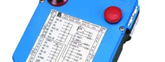
7 TRANSMITTER PARTS Stop Button ANTENNA LED indicator Rotary Key Switch Motion Buttons Motion Buttons Auxiliary Buttons Auxiliary Buttons Battery Cover TCM Page 7 of 31

 TCM260904")
8 Receiver s parts Antenna Receiver/ Decoder Module (inside) Relay Module (inside) Transformer (inside) TCM Page 8 of 31
9 INSTALLATION PRECAUTIONS DURING INSTALLATION (1) Observe all safety precautions when climbing the crane. (2) Turn off the main power source of crane before installation to avoid electric shock. (3) Receiver must be installed in such a way that it will not touch any part of the building during the operation. (4) Receiver must be fastened securely. (5) Two external antennas must be used when receiver is installed in a metal box. (6) Before installation, inspect the crane s safety devices, and make sure everything is in proper working condition. (7) Make sure you understand the crane circuits and power distribution as well as the function setting of remote controller, to avoid incorrect wiring. (8) To avoid any interference, the Receiver must be away from motors, frequency converter and power cable (show as below). (9) The Receiver should be installed on the top of the electrical control box. Don t mount the receiver inside. (Incorrect) Motor Antenna Receiver M (Electrical control box) Cable Receiver As far as possible Cable (Correct) Frequency Converter Receiver (Electrical control box) Cable TCM Page 9 of 31
 Select a place where you can see the Receiver or Antenna. (5) Select a place where there are no sparks, e.g. keep away from motors, relays, magnetic switches and power cables.")
 etc.")
 supplied in F21-12S/12D This could be set as required")
10 RECEIVER INSTALLATION INSTRUCTIONS PREPARATION FOR INSTALLATION (1) Provide all necessary tools. (2) Select a proper location. (3) Select a stable place. (4) Select a place where you can see the Receiver or Antenna. (5) Select a place where there are no sparks, e.g. keep away from motors, relays, magnetic switches and power cables. (6) Keep away from high-voltage wiring and devices. (7) The Receiver case must be at least 3 cm away from other obstacles. INSTALLATION OF PROPER POWER SOURCE The input power source for the receiver can be 110/220/380 VAC (50/60 Hz) etc. After the power source is confirmed, one must select the proper connector for the voltage applied to the relay module transformer primary winding. Selective power supply for F21-12S/12D as illustration as below: Power source plug 110V 220V 380V There are 3 kinds of voltage (110V/220V/ 380V) supplied in F21-12S/12D This could be set as required before shipment, or follow the procedures to change the voltage you need. (1) Turn off the Receiver. (2) Pull out the power source plug from the previous voltage position (3) Plug in the power source plug to the voltage you need. (4) Complete. Note: If the voltage you need is 48V/62V/110V, please contact distributor. Selective power supply for F21-6D as illustration as below: Black connector 110V 220V There are 2 kinds of voltage (110V/220V) supplied in F21-6D This could be set as required before shipment, or follow the procedures to change the voltage you need. (1) Turn off the Receiver. (2) Using tool to pull out the black connector from the previous voltage position. (3) Using tool to plug in the black connector to the voltage you need. (4) Complete. TCM Page 10 of 31
11 INSTALLATION SEQUENCE (1) Turn off the main power for the crane. (2) Attach the template (provided) for the receiver to the proper place. (3) Drill the holes for the screws, mount receiver, and then secure the receiver with 6mm nuts on the vibrationresistant feet. (4) Connect the cables to the control circuit of the crane according to the receiver s wiring chart and control contact diagram. NOTES (1) Inspect and make sure that all wires are connected correctly. (2) The earth ground for the remote controller and crane must be properly connected to ensure safety. (3) Secure the cables between the receiver and crane so that the cable bracket will not wear through due to the vibration of the crane. (4) Open the top cover of the receiver and turn the Relay module s Run/Test switch to the Test position. (5) Turn on the main power for the crane. (6) Operate the transmitter to test all functions and make sure they all operate correctly as shown by the LED indicators. (When the Run/Test switch is set to the Test position, the relays will not function, but the LEDs will display) (7) Turn the Run/Test switch to the Run position and secure the top cover to the receiver with screws. (8) This completes the installation of the receiver. TCM Page 11 of 31
12 OPERATION START UP Remove the cover of battery box. (1) Install 4 Fresh AA-size batteries in the battery box. Make sure the + and - directions are correct. (2) Attach back the battery cover. Note: Transmitter will sound two-long beeps to indicate the correct installation. (3) Turn on the power according to the Power-On Modes (see below). Note: LED indicator will flash with red colour if proper procedures are not followed. (4) Operate transmitter by pressing each pushbutton. (5) After operation, perform the following procedures in sequence: (1) Press EMS mushroom, (2) rotate key counter-clock-wise to the OFF position, (3) remove key and keep it in a safe place, (4) remove batteries if not used for a long period. POWER INDICATING FUNCTIONS OF LED DISPLAY. Green: Sufficient power to operate transmitter. (In order to save power, one can program to turn off LED display when power is sufficient.) Yellow: Power is depleting, warning sound occurs every 4 seconds (can be switched off and sound interval can be set by software). Operation must be stopped immediately (for example: lower the goods to ground) to replace batteries. Red: Insufficient power. In addition to red LED, warring sound will continue and transmitter will no longer function. Transmitter will send out an emergency stop signal to the receiver due to insufficient power. Operator should avoid this situation in order to maintain the safety of operation. POWER-ON OPERATION Power-on means that the Main-Relay on receiver will energize as soon as receiving the control data from transmitter and then receiver keep in condition of standby for continuous control. There are 4 different ways of Power-On mode could be setting. ANY PUSHBUTTON POWER-ON MODE (1) Rotate EMS mushroom clockwise 45º and pull out. (2) Turn key clockwise to ON position. (3) Press any pushbutton on the transmitter (or A, B switch). This will turn on the power as well as execute the function of pushbutton. START (MAGNETIC KEY SWITCH) POWER-ON MODE (1) Rotate EMS mushroom clockwise 45º and pull out. (2) Turn Key switch clockwise to ON position. (3) Turn Key switch 45º beyond ON position to turn on power. Note: When setting is on Any pushbutton power-on or Start pushbutton power-on, the transmitter is in the noncontinuous mode (i.e. pushbutton must be pressed to operate the function), it can save power. TCM Page 12 of 31
13 E.U. STANDARD POWER-ON MODE (1) Rotate EMS mushroom clockwise 45º and pull out. (4) Turn Key switch clockwise to ON position. (2) Turn Key switch 45º beyond ON position to turn on power. (3) After 3 minutes of non-operation, transmitter will send out an emergency stop signal to the receiver. When this occurs, one must turn the magnetic key counter-clockwise to the OFF position, then turn the key clockwise to the ON position, and press Start pushbutton to turn on the power. Note: When setting is on E.U. standard Power-on Mode, the transmitter is in the continuous mode. SOFTWARE POWER-ON MODE This Power-On mode is controlled by the software. It consists of: (1) Whether the receiver Power-Off automatically when no operation for a period of time. (2) Whether a password is required to turn on power. (3) Whether an emergency stop signal will be sent out etc. ACCELERATION / DECELERATION OPERATION Note: (1) South pushbutton is the acceleration pushbutton; North pushbutton is the deceleration pushbutton. (2) When a motion is in the second speed, quick touch of acceleration pushbutton will double the speed. Repeated touch of acceleration pushbutton will increase the speed up to 5 times. (3) To reduce the speed, touch the deceleration pushbutton. Repeated touch of deceleration pushbutton will reduce to the second speed. (1) When accelerate/decelerate, the motion pushbutton must be depressed and held in the second speed. If motion pushbutton is released, there will be no acceleration/deceleration and speed will return to zero. (2) Press North pushbutton will perform the Alarm function if the speed is reduced to the second speed. INCHING OPERATION (1) South pushbutton is set for inching pushbutton. (2) Press and hold inching pushbutton. (3) Press any motion pushbutton to perform the inching motion. Note: The other pushbutton of transmitter must be released before press inching pushbutton. TCM Page 13 of 31
14 CHANGE OF FREQUENCY This remote controller provides 3 operating frequencies. When remote controller is interfered by radio wave and can t operate properly, the operator can change the transmitter s frequency according to the following procedures without changing the channel in the receiver. This eliminates the trouble of climbing to the receiver. Note 1: From the transmitter, one can depress the corresponding pushbutton to change operation frequency. In the meantime, LED indicator displays different colours to show the operation frequency as follows: Operation frequency LED Colour Corresponding pushbutton Frequency A Red Up pushbutton Frequency B Yellow Down pushbutton Frequency C Green East pushbutton Note 2: From the transmitter, one can follow to the below-mentioned procedures to check the operation frequency. (1) Press EMS mushroom. (2) Turn security key to Off position and then turn security key clockwise from Off to On position. (3) At this moment, LED indicator will display the corresponding colour to show the present operation frequency of transmitter. Note 3: Both receiver and transmitter must be in the same operation frequency to operate properly. (e.g. both in Frequency A, or B, or C). Note 4: Channels 1 to 256 can be set by Dip switch in the receiver or set by software. A 1 A 2...A 256 B 1 B 2. C 1 C 2. C 256 Dip switch in the receiver is an 8-bit for 256 channels. If current setting is channel 16, one can choose among frequency A16, B16, C16. Bandwidth of each section and separation between channels can be set by software. e.g. A1=430,000MHz A2=430,025MHz.. A255=436,375MHz; B1=436,400MHz etc. TCM Page 14 of 31
15 PROCEDURE FOR CHANGING OPERATION FREQUENCY: Step Action Remark 1 Press EMS mushroom. 2 Turn key to Off position. 3 Depress and hold the pushbutton in accordance with the frequency that you want to change. Note: The pushbutton must be depressed and held until step 6 is completed. 4 Turn key clockwise from Off to On position 1. Up pushbutton = Frequency A 2. Down pushbutton = Frequency B 3. East pushbutton = Frequency C 5 Turn key counter-clockwise from On to Off position once LED indicator is ceased flashing. 6 Compete 7 Power-On according to the proper procedure described previously and return to normal operation. ENTER PASSWORD OPERATION (1) Rotate EMS mushroom clockwise 45º and pull out. (2) Turn key clockwise to ON position. (3) Press the pushbutton sequentially to enter password within 10 seconds. (Remark: This time duration of Password Complete can be set by software. At the duration of Password Complete the LED indicator will flash with Green colour.) (4) The buzzer of transmitter will sound one-long sound to indicate the password is correct. After buzzer turns off, Power-On according to the proper procedure and return to normal operation. (5) If password is incorrect then the buzzer will sound with two-short sound and one long sound. Enter the correct password again after buzzer is turned off. Note 1: The function of password can be set by software in order to avoid unauthorized people to use remote controller. Note 2: One must re-enter password to return to normal operation if EMS mushroom has been pressed (or emergency stop signal has been transmitted due to transmitter auto power off). TCM Page 15 of 31
16 FUNCTION SETTING The operation of the controller can be modified to suit a specific application, using a PC with a special interface cable. For further information please contact your distributor. START SWITCH FUNCTION SETTING: Item Title Options Description A Function 1. No Function 2. Alarm 3. Normal 4. Toggle UP/DOWN PUSHBUTTON FUNCTION SETTING: This function is available only when remote controller is in Power-On mode. Alarm : The alarm relay will close and the receiver alarm will sound if the rotary key switch is rotated to the Start position, and the alarm relay will turn off when the rotary key switch is released. Normal : The associated relay is on when the pushbutton is pressed and held, and is off when the pushbutton is released. Toggle : Press the pushbutton and release once for on, re-press and release for off. Item Title Options Description A Interlock 1. Interlock 2. Non-Interlock Interlock : If the motions cannot be operated simultaneously then select Interlock. Non-Interlock : If the motions are allowed to operate simultaneously then select Non-Interlock. This item is selectable only when UP and DOWN pushbuttons are set at Normal function. B Function UP: DOWN: 1. Normal Normal 2. Toggle Normal 3. Toggle Toggle 4. On Off Normal : The associated relay is on when the pushbutton is pressed and held, and is off when the pushbutton is released. Toggle : Press the pushbutton and release once for on, re-press and release for off. ON & OFF : The two pushbuttons are set to respectively control the same relay. If a pushbutton set as on is pressed and released, then the relay remains closed. No other pushbutton can change the status of this relay except the pushbutton set as off. TCM Page 16 of 31
17 EAST/WEST PUSHBUTTON FUNCTION SETTING: Item Title Options Description A Interlock 1. Interlock 2. Non-Interlock Interlock : If the motions cannot be operated simultaneously then select Interlock. Non-Interlock : If the motions are allowed to operate simultaneously then select Non-Interlock. This item is selectable only when East and West pushbuttons are set at Normal function. B Function Normal : The associated relay is on when the East: West: pushbutton is pressed and held, and is off when the 1. Normal Normal pushbutton is released. 2. Toggle Normal Toggle : Press the pushbutton and release once for on, re-press and release for off. 3. Toggle Toggle ON & OFF : The two pushbuttons are set to respectively control the same relay. If a pushbutton set as 4. On Off on is pressed and released, then the relay remains closed. No other pushbutton can change the status of this relay except the pushbutton set as off. SOUTH/NORTH PUSHBUTTON FUNCTION SETTING: Item Title Options Description A Interlock 1. Interlock 2. Non-Interlock Interlock : If the motions cannot be operated simultaneously then select Interlock. Non-Interlock : If the motions are allowed to operate simultaneously then select Non-Interlock. This item is selectable only South and North pushbuttons are set at Normal function. B Function South: North: 1. Normal Normal 2. Toggle Normal 3. Toggle Toggle 4. On Off Normal : The associated relay is on when the pushbutton is pressed and held, and is off when the pushbutton is released. Toggle : Press the pushbutton and release once for on, re-press and release for off. ON & OFF : The two pushbuttons are set to respectively control the same relay. If a pushbutton set as on is pressed and released, then the relay remains closed. No other pushbutton can change the status of this relay except the pushbutton set as off. TCM Page 17 of 31
18 R1/R2PUSHBUTTON FUNCTION SETTING: Item Title Options Description A Interlock 1. Interlock 2. Non-Interlock B Function R1: R2: 1. Normal Normal 2. Toggle Normal 3. Toggle Toggle 4. On Off Interlock : If the motions cannot be operated simultaneously then select Interlock. Non-interlock : If the motions are allowed to operate simultaneously then select Non-Interlock. This item is selectable only when R1 and R2 pushbuttons are set at Normal function. Normal : The associated relay is on when the pushbutton is pressed and held, and is off when the pushbutton is released. Toggle : Press the pushbutton and release once for on, re-press and release for off. ON & OFF : The two pushbuttons are set to respectively control the same relay. If a pushbutton set as on is pressed and released, then the relay remains closed. No other pushbutton can change the status of this relay except the pushbutton set as off. R3/R4 PUSHBUTTON FUNCTION SETTING: Item Title Options Description A Interlock 1. Interlock 2. Non-Interlock B Function R4: R3: 1. Normal Normal 2. Toggle Normal 3. Toggle Toggle 4. On Off Interlock : If the motions cannot be operated simultaneously then select Interlock. Non-interlock : If the motions are allowed to operate simultaneously then select Non-Interlock. This item is selectable only R3 and R4 Pushbuttons are set at Normal function. Normal : The associated relay is on when the pushbutton is pressed and held, and is off when the pushbutton is released. Toggle : Press the pushbutton and release once for on, re-press and release for off. ON & OFF : The two pushbuttons are set To respectively control the same relay. If a pushbutton set as on is pressed and released, then the relay remains closed. No other pushbutton can change the status of this relay except the pushbutton set as off. TCM Page 18 of 31
19 R5/R6 PUSHBUTTON FUNCTION SETTING (The function of R5 pushbutton also can be set by dip switch that locate on the Receiver/Decoder Module) Item Title Options Description A EMS 1 Bypass. EMS 2. Control by EMS B R5 Function 1.Normal 2.Toggle 3.Inching 4.Acceleration Bypass EMS means that the relays associated with the R5/R6 pushbuttons will not be controlled by the EMS mushroom or an emergency stop signal. Control by EMS means that the relays associated with the R5/R6 pushbuttons are controlled by the EMS mushroom or an emergency stop signal. Normal : The associated relay is on when the pushbutton is pressed and held, and is off when the pushbutton is released. Toggle : Press the pushbutton and release once for on, re-press and release for off. Inching : Inching means that when the pushbutton is pressed then the associated relay will be closed for a certain time, in order to operate with short, precise movements. Press and hold inching pushbutton and then press a motion pushbutton to perform the inching motion. Inching time is from 0.1~0.5 sec and 0.01~0.09 sec, and can be set by software or DIP switch. Acceleration : The R5 pushbutton can be selected as an acceleration pushbutton if the crane s speed is three or more speeds. When a motion is in the 2 nd speed, a quick touch of the acceleration pushbutton will increase by one speed and the associated relay of R5 will close. When using acceleration, the motion pushbutton must be depressed and held in the 2 nd speed. If the motion pushbutton is released, there will no acceleration and the speed will return to zero. C R6 Function 1. Normal 2. Toggle 3. Deceleration 4. No function D Inch. Time sec ~0.5 sec ~0.09 sec Normal : The associated relay is on when the pushbutton is pressed and held, and is off when the pushbutton is released. Toggle : Press the pushbutton and release once for on, re-press and release for off. Deceleration : Touch deceleration pushbutton to reduce speed. Repeat touches of deceleration pushbutton will reduce to 2 nd speed. Inching time can be set from 0.1~0.5 sec and 0.01~0.09sec. This function is used for operating the crane with short and precise movements (e.g. accurate position). Inching Time is the amount of time the associated relay is. TCM Page 19 of 31
20 OTHER TRANSMITTER FUNCTIONS Item Title Options Description A Power-On 1. Mushroom or key 2. Mushroom 3. Key 4. Any pushbutton 5. Start pushbutton 6. E.U. ( standard) 7. E.U. ( simple) B Auto Off 1. No 2. Yes C Transmit 1. Non-continuous 2. Continuous Power-ON : It means that the stop relay of receiver is energized. Mushroom or Key Power-On mode : This mode means that the receiver will be in the Power-On mode if one of the Mushroom Power-On or Key Power-On is executed. Mushroom Power-On mode : The receiver will be in the Power-On mode when the mushroom is pulled out, when the key is in the on position. Key Switch Power-On mode : The receiver will be in the Power-On mode when the rotary key switch is turned from off to on position, when the mushroom is in the off position (i.e. mushroom is pulled up). Any pushbutton Power-On mode : The receiver will be in the Power-On mode when any pushbutton on the transmitter is pressed, when mushroom is at off (i.e. pulled out) position and key is at on position. Start pushbutton Power-On mode : The receiver will be Power-On once Start pushbuttons is pressed, when mushroom is at off position and key is at on position. E.U. (standard) Power-On mode : The receiver will be in the Power-On mode when the rotary key switch is rotated to the Start position, when the mushroom is at off position. In case the receiver is Powered off due to the mushroom being pressed or Auto Off, one must turn the rotary key switch to off position, then turn to on position, and to Start position to turn on the power. This mode is continuously transmitting and will automatically turn off after 3 minutes of non-operation. E.U. (simple) Power-On mode : The receiver will be in the Power-On mode once the rotary key switch is rotated to Start position, when mushroom is at off position and key is at on position. The only difference from E.U. (standard) is that in this mode, one doesn t need to turn the rotary key switch to off position and then to on position to re-start. Auto Off : The transmitter will turn off the power supply automatically if there is no operation for a certain time. Whether to transmit an EMS signal to Power-Off the receiver before the transmitter turns off can be set by this function. Power-off means that the Stop Relay of receiver is deenergized. Hence, one must perform the Power-On procedure to turn on the receiver power. Non-continuous transmitting mode : After Power- On, the transmitter will transmit a signal only when the pushbutton is pressed. This mode can save the transmitter battery power. Continuous transmitting mode : The transmitter will continuously transmit a signal while Powered on. TCM Page 20 of 31
21 D E Save Power 1. 3 min sec, 1 min, 90 sec, 2 min 3 min, 4 min, 5 min, Not execute Alarm mode 1. Simple alarm mode 2. Morse alarm mode F Password 1. No 2. Yes G Password set 1. By pushbutton 2. By software Save Power : The transmitter will turn off the power supply automatically if there is no operation for a certain time, in order to save power. Only the transmitter is in the continuous transmitting mode is this function available.. Simple alarm mode : If the self-diagnostic detects a malfunction then the buzzer will sound to indicate the error message, one long sound means Encoder module malfunction, two long sounds mean transmitter RF module malfunction, three long sounds mean power supply malfunction. During operation this mode is used to indicate a fault situation. Morse alarm mode : There are 5 kinds of Morse code to report a detailed error message. Normally this mode is used to indicate individual malfunctioning parts. This item is used to set the password function. The operator has to enter the password before turning on the transmitter if Yes is selected. This function is like an electronic-key that can prevent unauthorized persons from operating the remote controller. Password entry procedure : When the EMS mushroom is in the off (pulled up) position and the rotary key switch is in the on position, press the pushbuttons sequentially to enter the password (During the password entry period, Password Complete, the LED indicator will flash green). The transmitter buzzer will sound one long beep if password is correct. After buzzer turns off, power-on according to the proper procedure and return to normal operation. If the password is incorrect then the buzzer will sound with two short beeps and one long beep ( ). Enter the correct password again after buzzer turns off. If the password function is set as Yes then the Password code can be set by pushbutton or by software. Setting password by pushbutton: Depress the EMS mushroom and turn the rotary key switch to the off position. Depress and hold both UP & DOWN pushbuttons and then turn the rotary key switch from off to on position simultaneously. At this time, the LED will flash red and green alternately for 10 seconds. Press the pushbuttons sequentially to key in a new password within 10 seconds. The buzzer will sound three long beeps when the password setting procedure is finished. The length of the password is four-digits, for example: Up, Up, Down, Up. Pull up EMS mushroom and enter new password to turn on transmitter. This function is designed for authorized and qualified operators to set or change the password if they forget the original one. Because other people do not understand this procedure, it can prevent unauthorized persons from operating the remote controller. Setting password by software : It means that the password can only be set by software. TCM Rev 0.1 TCM Page 21 of 31
22 H E.U. Start 1. EU (Standard) 2. EU (Simple) I J Normal OP 1. LED-off 2. LED-on Password Complete E.U. Start : If E.U.(standard) is selected is the mode for Power-On, when the EMS signal is automatically sent out by the Transmitter and the Main Relay in the Receiver is turned off in the auto off mode, to start the Power-On operation again by the Transmitter, if E.U. (Standard) is selected, one must turn the rotary key switch to the positions ON OFF ON START in order to set the receiver to Power-On mode, if E.U. (Simple) is selected only rotate the rotary key switch to the Start position to Power-On the Receiver. Note: Auto Off means that the Transmitter will turn off the power supply automatically if there is no operation for a certain time. If E.U.(standard) is selected for the Power-On, mode, to turn the rotary key switch according to the positions ON OFF ON START in order to Power-On the Receiver after the EMS mushroom is pressed. LED-off : The LED indicator will be shut off during normal operation in order to save power. But it is still available for warning and fault indication. LED-on : LED indicator will light up green when transmitter is transmitting. It is still available for warning and fault indication with first priority Seconds Password Complete : If the password function is 2. 4, 5, 10, 15, 20, 25, selected, this function determines the time to enter the password. If the password is not entered within the 30, 40, 50, 60 sec. password complete time, it must be re-entered from the beginning. TCM Rev 0.1 TCM Page 22 of 31
23 OTHER RECEIVER FUNCTIONS: Item Title Options Description A Auto Off 1. 1 hour minutes 20 minutes 30 minutes 1 hour 2 hours 3 hours 4 hours not execute B Function dip 1. Enable 2. Disable C Alarm mode 1. Simple alarm mode 2. Morse alarm mode D Acc. delay 1. 2 sec sec, 0.5 sec 1 sec, 1.5 sec 2 sec, 3 sec 4 sec E Channel DIP 1. Enable 2. Disable Receiver Auto Power-Off : If the receiver doesn t receive the correct control data within a certain time, then the Stop relay on the receiver will be de-energized automatically (i.e. receiver Power-Off). Normally this function is used with the non-continuous transmitting mode to shut the crane off if the operator forgot to turn off the transmitter. Function DIP : This setting determines whether the DIP switch on the Receiver/Decoder module of Receiver is used to set functions. If Disable is selected, then the function setting is fully controlled by software. Simple alarm mode : If the self-diagnostic detects a malfunction then the alarm will sound to indicate the error message, one long sound means Relay module malfunction, two long sounds mean Receiver/Decoder module malfunction, three long sounds mean power failure. During operation, this mode is used to indicate fault situation. Morse alarm mode : There are 22 kinds of Morse code to report a detailed error message. Normally this mode is used to indicate individual malfunctioning parts. Acceleration delay time : This function is used to set the time interval between acceleration relays closing. It is used for accelerating operations only in order to prevent the crane from running directly to the highest speed which can damage the motor. Channel Dip : This setting determines whether the DIP switch on the Receiver/Decoder module of the Receiver is used to set the channel. If Disable is selected, then the channel setting is fully controlled by software. TCM Page 23 of 31
24 SETTING OF CHANNELS Item Title Options Description A Channel 1 ~ 256 Channel setting : This remote controller provides three frequency ranges A, B and C, that can be changed by transmitter s pushbuttons directly. Each frequency range has 256 channels. The operating channel in each range will be changed simultaneously if a new channel number is set by DIP switch or software. For example: If the original channel number is 1, then the operating channels are A 1, B 1 and C 1. If the channel number is changed from 1 to 24 then the operating channels will be A 24, B 24 and C 24.The operating frequency of A 24 is equal to A 1 + channel spacing (24 1). PASSWORD CODE SETTING Item Title Options Description A Password code 0 ~ 9 This item is available when the Password set function is set as By software. Password code Sets the password code. The code length is four-digits. These numbers 0~9 are used to indicate the corresponding pushbutton. FUNCTION SETTING BY RADIO: (1) Use a PC or maintenance kit to program the function settings into the transmitter in advance. (2) Depress EMS mushroom and turn rotary key switch to the off position. (3) Depress and hold both Up & East pushbuttons and turn key from off to on position simultaneously. (4) Release Up & East pushbuttons. At this time, the LED indicator will flash with yellow and red colour alternately. (5) After the receiver alarm sounds two short beeps and one long beep (two short beeps and one long beep means that function setting is completed), turn key from on to off position. (6) Power-On according to the proper procedure and return to normal operation. TCM Page 24 of 31
25 INSPECTION AND MAINTENANCE INSPECTION Daily inspection is important and will ensure the safety of operation. Inspection should include emergency stop and other safety devices and functions. If there is any doubt, operation must be stopped immediately and problems must be solved before resume of operation. MAINTENANCE This remote controller is equipped with self-diagnostic device. During the operation and the change of batteries, self-diagnostic device will activate the warning alarm if any malfunction is detected. Operator must understand the malfunction signals and notify the maintenance personnel. Malfunctions and warning alarm are listed as follows: Note: When dip switch setting is on Simple alarm mode, alarm signals are shown on the list; when dip switch setting is on Morse alarm mode, please refer to Technician s Manual.) Malfunction Part Error message Alarm Signal Remark Encoder Module malfunction Alarm lasts 0.5 second repeats every 2 seconds Transmitter RF Module malfunction Refer to Note below Insufficient power to operate transmitter Refer to Note below Relay Module malfunction Alarm lasts 0.5 second repeats every 2 seconds Receiver Receiver/Decoder Module malfunction Refer to Note below Power failure Refer to Note below Note: Each indicates 0.5 second alarm. Each short interval lasts 0.5 second, and long interval lasts 2 seconds. For example, the error message of RF Module Malfunction: short interval (0.5 sec) long interval (2 seconds). TCM Page 25 of 31
26 TROUBLESHOOTING SELF-DIAGNOSTICS In order to simplify maintenance, this remote control system has been designed with a built-in self-diagnostics circuit in the transmitter and receiver. As long as the micro control unit is in proper working condition, malfunctions in the pushbutton, joystick, RF circuit, relay and relay driver circuits (including relay coil and relay contacts) can be detected. When a malfunction occurs, the transmitter or receiver will generate a simple and clear alarm. Not only can the operator and maintenance personnel fully understand the condition of the remote controller, but they can also reduce maintenance time by following the error message for repair. NOTES: (1) When an error message is detected by the receiver or transmitter s self-diagnostics, an alarm will sound and Power-OFF will be activated. Until the malfunction has been corrected, it will be impossible to Power-On the controller. (2) Maintenance Technicians can use the error messages. However, we recommend the technician replace only the module. The defective module should be returned to our distributor for component-level repair. This will eliminate further damage to the controller. (3) If you do not understand the error message from the transmitter or receiver, or the signal is not listed in this manual, please contact our distributor for clarification and advice. TCM Page 26 of 31
27 TRANSMITTER MALFUNCTIONS AND SOLUTIONS Item Error Message Morse Code Problem Solution 1 C 2 D 3 F 4 R Malfunction of E 2 PROM memory in the encoder module; cannot be read or written. E 2 PROM in the encoder doesn t have function settings or settings are incomplete. Malfunction of pushbutton. (shorted) Batteries dead Replace encoder module. Perform the function setting procedure (Refer to section 3-4) Perform the function setting procedure (Refer to section 3-4) Replace encoder module. Perform the function setting procedure. (Refer to section 3-4 ) Replace batteries 5 S RF module malfunction Replace RF module Note: RF module s channel must be set the same as that of the receiver. Note: (1) If a pushbutton malfunction occurs the buzzer will sound and the LED indicator will flash red simultaneously when the power is reset (e. g. change of batteries). During operation the transmitter will perform self-diagnostics when the EMS mushroom is pressed. If the malfunction in item 3 occurs, only the LED indicator (flashing red) will indicate the error message when you press the EMS mushroom. (2) The alarm for the other items will sound only when you push the pushbuttons or when the power source is reset (e. g. change of batteries). TCM Page 27 of 31
28 RECEIVER MALFUNCTION AND CORRECTION Item Error Message Morse Code Problem Solution 1. A UP relay coil damaged 2. B U/D 2S relay coil damaged 3. C DOWN relay coil damaged 4. D EAST relay coil damaged 5. E E/W 2S relay coil damaged 6. F WEST relay coil damaged 7. G SOUTH relay coil damaged 8. H S/N 2S relay coil damaged 9. I NORTH relay coil damaged Replace Relay module 10. J R1 relay coil damaged 11. K R1/R2 2S relay coil damaged 12. L R2 relay coil damaged 13. M R3 relay coil damaged 14. N R3/R4 2S relay coil damaged 15. O R4 relay coil damaged 16. P MAIN relay coil damaged Q Relay contacts are jammed (can t open) at COM 1. R The input power voltage is out of tolerance. S RF circuit malfunction Disconnect the cable from the receiver. Turn off the main power of the crane and check the input power voltage. Check whether the voltage select plug is in the correct position Inspect and make sure the power is normal before resuming operation. Replace Receiver/decoder module TCM Page 28 of 31
29 20. Y Interference by the same model of remote controller Change to a new frequency Interference by another radio signal on the same frequency. If interference is not serious, Power- On the remote controller when the interference is over. If interference is serious, change to new frequency. (Refer to section at operator s Manual) 22. Z E 2 PROM in the Receiver/ decoder doesn t have function setting s or settings are incomplete. Contact distributor for programming of function settings. Note: (1) When the receiver s self-diagnostics detect a malfunction, the alarm will continue, until the malfunction has been corrected or the power to the receiver is disconnected. (2) The receiver can be set by the software to sound the alarm or not, when an error occurs relating to item 20 ~ 21. (3) The receiver can be set by software to stop the affected action (i.e. Relay-Off ) or Power-Off automatically, when the error occurs relating to items 20 ~ 21. For the other items, the receiver will enter into the Auto Power-Off mode. (4) This receiver contains an Automatic Gain Control circuit with high sensitivity; when not in operation, it may receive weak signals from unknown sources. As long as the interference does not occur very often, it will not affect the normal operation. No frequency change is necessary. TCM Page 29 of 31
30 MALFUNCTION IDENTIFICATION. When the remote controller does not function properly (e. g. Receiver does not function correctly after pressing a pushbutton on the transmitter) and there is no malfunction alarm information, please follow the procedures below to diagnose the malfunction. Item Problem Action Required 1. Transmitter s LED and buzzer do not react at all. 2. Transmitter is normal but receiver s buzzer doesn t react at all. Make sure battery power is normal: Check battery direction. Check battery compartment direction. Check battery condition. Make sure micro control unit (MCU) is normal: Press EMS mushroom and turn rotary key switch to OFF position. Remove the battery cover, wait 10 seconds, and insert the battery cover again. At this time, the buzzer should generate two long sounds. Otherwise, the MCU is out of order or the power connecting wire is bad. 3.Return for repair. Make sure the receiver s power source is normal: Inspect the Receiver/Decoder to see if the SQ indicator light is on and the ANT A and ANT B lights flash alternately. Inspect the AC power fuse and DC power fuse to see if a fuse is blown out. If necessary, turn off the main power and replace the fuse. Make sure the Receiver/Decoder module and Relay module are wired correctly. Make sure the relay output fuse is not blown. Replace fuse if necessary. Make sure the Alarm relay is not out of order. (If the Alarm LED is on, it means the relay is out of order.) 5. Return for repair. 3 A certain motion does not work. 1. Make sure the relay output fuse is not blown. Replace fuse if necessary. 2. Make sure the original control system of the crane works properly. If not, ask the original manufacturer to repair. 3. Return for repair. TCM Page 30 of 31
31 REVISION HISTORY 0.0 original document created from manufacturers documents 0.1 Start operation with magnetic key switch updated TCM Page 31 of 31
Installation & Operation Manual SAGA1-K Series Industrial Radio Remote Control
 Installation & Operation Manual SAGA1-K Series Industrial Radio Remote Control Gain Electronic Co. Ltd. Table Of Contents Safety Considerations ------------------------------------------------------------2
Radio Remote Controls Series D1 / D2
 Radio Remote Controls Series D1 / D2 P/N 701D0031 2008.09.26 Rev. 3 D1 / D2 Radio Control Manual 1 Conductix Incorporated The technical data and images which appear in this manual are for informational
FCC ID: SAGA1-L8 IC: 2802A-SAGAL8 CE0470
 FCC ID: SAGA1-L8 IC: 2802A-SAGAL8 CE0470 WARRANTY INMOTION Controls, Inc. guarantees that this product meets its published specification at the time of shipment from the factory. Under proper installation,
INSTALLATION & OPERATION MANUAL
 INSTALLATION & OPERATION MANUAL PREFACE This installation & operation manual is intended as an instruction manual for trained person who is in charge of installation, maintenance, repair, etc. Before installation
INMOTION Controls Series INSTALLATION & OPERATION MANUAL. INMOTION Series - INMOTION INMOTION-260. Page: 1/15
 INSTALLATION & OPERATION MANUAL INMOTION Series - INMOTION-220 - INMOTION-260 Page: 1/15 PREFACE This installation & operation manual is intended as an instruction manual for trained persons who are in
Radio Remote Controls Manual Series L12
 Radio Remote Controls Manual Series L12 1 Conductix Incorporated The technical data and images which appear in this manual are for informational purposes only. NO WARRANTIES, EXPRESS OR IMPLIED, INCLUDING
TeleChief Series TM2200HT
 TeleChief Series TM2200HT Owner s Manual Failure to return the Warranty Registration document (enclosed) to Control Chief within 30 days of purchase will void any warranty responsibilities on behalf of
Radio Control Manual Series L10
 Radio Control Manual Series L10 1 Conductix Incorporated The technical data and images which appear in this manual are for informational purposes only. NO WARRANTIES, EXPRESS OR IMPLIED, INCLUDING WARRANTIES
Alpha 3000 I n d u s t r i a l R a d i o R e m o t e C o n t r o l S y s t e m Operation & Parts Manual
 Alpha 3000 I n d u s t r i a l R a d i o R e m o t e C o n t r o l S y s t e m Operation & Parts Manual Williams USA, LLC 38113 Plymouth Rd., Livonia, Michigan 48150 Phone: 1-734-416-5520, Fax: 1-734-416-1907
MRT. Instruction Manual. Remote Crane Controls. PSMRTINST-01A October, 2001 Part Number: Copyright 2001 Electromotive Systems
 Remote Crane Controls MRT Instruction Manual PSMRTINST-01A October, 2001 Part Number: 900-4128 Copyright 2001 Electromotive Systems 2001 ELECTROMOTIVE SYSTEMS All rights reserved. This notice applies to
Radio Remote Controls Manual K Series
 Radio Remote Controls Manual K Series PN 52764 2010.12.20 Rev. 2 K Series radio control manual 1 Conductix Incorporated The technical data and images which appear in this manual are for informational purposes
IMPORTANT! Please take the time to read through the manual before you start to install/program your equipment.
 PRODUCT DESCRIPTION IMPORTANT! Please take the time to read through the manual before you start to install/program your equipment. The systems KRC11, 12, 13 and 14 consists of two parts: the transmitter
English RACON SERIES II RADIO CONTROL SERVICE MANUAL
 English 22.2.2007 RACON SERIES II RADIO CONTROL SERVICE MANUAL Read the instructions supplied with the product before installation and commissioning. Keep the instructions in a safe place for future reference.
R PROFLAME Instruction Book Collection
 9.956.028 R00 584 PROFLAME Instruction Book Collection 4-17 18-29 584 PROFLAME System 30-39 Appendix: DIP SWITCH NUMBER (0=ON 1=OFF) 40-41 4-17 Fig. 1 The SIT is a device that allows, in conjunction with
OSMAC RDR Low-voltage Retrofit Kit
 OSMAC RDR Low-voltage Retrofit Kit Part Number RDR0160LVN0 User s Guide Installation of the RDR (Radio Data Receiver) low-voltage unit will enable you to remotely operate your existing Vari-Time 4000 satellite
WARRANTY. Long Range Systems, LLC, 20 Canal St, Suite 4N, Franklin, NH 03235
 WARRANTY Long Range Systems, Inc. warrants the trap release product against any defects that are due to faulty material or workmanship for a one-year period after the original date of consumer purchase.
Radio Remote Controls Manual K Series
 Radio Remote Controls Manual K Series 1 PN 52764 2010.12.20 Rev. 2 K SERIES RADIO CONTROL MANUAL Conductix Incorporated The technical data and images which appear in this manual are for informational purposes
MEGA REMOTE RADIO REMOTE CONTROL SYSTEM
 RADIO REMOTE CONTROL SYSTEM -PRELIMINARY- INSTALLATION AND OPERATION MANUAL NORWOOD 3A2481CJ.doc April 15, 2014 BJ INDEX DESCRIPTION... 2 TRANSMITTER AND RECEIVER SYNCHRONIZATION... 3 CLONING TRANSMITTERS...
SPECIFICATION EP 1000/1500/2000 Series
 UNINTERRUPTIBLE POWER SYSTEM SPECIFICATION EP 1000/1500/2000 Series Page 1 of 28 1.0 Revision Summary REVISION SECTION DESCRIPTION Formal Release Page 2 of 28 Table of Contents 1. Introduction. 4 2. Block
INSTRUCTION MANUAL VHF FM TRANSCEIVER TK-7102H UHF FM TRANSCEIVER TK-8102H KENWOOD CORPORATION B (M)
") INSTRUCTION MANUAL VHF FM TRANSCEIVER TK-7102H UHF FM TRANSCEIVER TK-8102H KENWOOD CORPORATION B62-1596-00 (M) 09 08 07 06 05 04 03 02 01 00 THANK YOU! We are grateful you chose KENWOOD for your personal
INSTRUCTION MANUAL VHF FM TRANSCEIVER TK-7102H UHF FM TRANSCEIVER TK-8102H KENWOOD CORPORATION B62-1596-00 (M) 09 08 07 06 05 04 03 02 01 00 THANK YOU! We are grateful you chose KENWOOD for your personal
Lazerpoint TM RF RX-91 Basic Receiver Installation Instructions
 Lazerpoint TM RF RX-91 Basic Receiver Installation Instructions Ver. 1.01 Section 1 General Description Camden Lazerpoint Radio Controls comprise the following models: - CM-TX-9 Wall switch ready transmitter
2011 / Circuit Tracer
 INSTRUCTION MANUAL 2011 / 00521 Circuit Tracer Read and understand all of the instructions and safety information in this manual before operating or servicing this tool. 52044992 2008 Greenlee Textron
The system (EF-7700) consists out of two parts: the transmitter (EF-7602) and the receiver including wiring (EF-7701).
 consists out of two parts: the transmitter (EF-7602) and the receiver including wiring (EF-7701).") PRODUCT DESCRIPTION IMPORTANT! In order to get the best out of your system it is important you take the time to read through the manual before you start to install/program your equipment. The system (EF-7700)
PRODUCT DESCRIPTION IMPORTANT! In order to get the best out of your system it is important you take the time to read through the manual before you start to install/program your equipment. The system (EF-7700)
INSTALLATION AND OPERATION MANUAL
 RADIO/CAN REMOTE CONTROL SYSTEM -PRELIMINARY- INSTALLATION AND OPERATION MANUAL SDP GREEN 3B1151AJ.doc September 3, 2009 AP INDEX DESCRIPTION... 2 TRANSMITTER AND RECEIVER SYNCHRONIZATION... 3 INDICATOR
MobileRadio. Owner'sManual
 EMH MobileRadio Owner'sManual TABLE OF CONTENTS Introduction... 1 Basic Operation... 2 Code Guard Operation... 3 EMH Radio Controls... 4 Button Functions... 4 Built-in Features... 7 Keypad Microphone Operation...
WS-29 DUAL CHANNEL WIRELESS BELTPACK
 WS-29 DUAL CHANNEL WIRELESS BELTPACK USER MANUAL Issue March 2011 ASL Intercom BV DESIGNED AND MANUFACTURED BY: ASL INTERCOM BV ZONNEBAAN 42 3542 EG UTRECHT THE NETHERLANDS PHONE: +31 (0)30 2411901 FAX:
1- Description CONTENTS
 UM Series Typical applications : Handling / Industrial lifting Travelling cranes, gantry cranes Air handling systems Self-propelled devices Industrial vehicles Hydraulic cranes on truck Industrial equipment
Model 7000 Low Noise Differential Preamplifier
 Model 7000 Low Noise Differential Preamplifier Operating Manual Service and Warranty Krohn-Hite Instruments are designed and manufactured in accordance with sound engineering practices and should give
WRM-10 TM TRANSFORMER WINDING RESISTANCE METER
 WRM-10 TM TRANSFORMER WINDING RESISTANCE METER USER S MANUAL Vanguard Instruments Company, Inc. 1520 S. Hellman Ave. Ontario, California 91761, USA TEL: (909) 923-9390 FAX: (909) 923-9391 June 2009 Revision
Cat. No. H8861 Model: RCL-S-STAT
 -AAA Cat. No. H8861 Model: RCL-S-STAT INSTALLATION AND OPERATION INSTRUCTIONS IF YOU CANNOT READ OR UNDERSTAND THESE INSTALLATION INSTRUCTIONS DO NOT ATTEMPT TO INSTALL OR OPERATE INTRODUCTION This remote
Receiver Type /Version Factory No. Frequency. Transmitter Type /Version Factory No. Frequency
 Receiver Type /Version Factory No. Frequency Transmitter Type /Version Factory No. Frequency 1. STANDARD SPECIFICATION Portable transmitter. Receiver with integrated mounting holes. Multi-pin connecting
Radio Controls Manual Protean Series
 Radio Controls Manual Protean Series 1 CONDUCTIX INCORPORATED The technical data and images which appear in this manual are for informational purposes only. NO WARRANTIES, EXPRESS OR IMPLIED, INCLUDING
Installation instructions
 Installation instructions T70RX-03AIB, T70RX-03AWB, T70TX-02TTB, T70TX-03STB, T70TX-06TTB LANGUAGE: English (original) IM-T70-RX001-A01-EN CONTENTS Chapter 1: CUSTOMER INFORMATION 3 Chapter 2: PRODUCT
GC-1032 Metal Detector OWNER S MANUAL
 GC-1032 Metal Detector OWNER S MANUAL 1 With your GC-1032 metal detector, you can hunt for coins, relics, jewelry, gold, and silver just about anywhere. The detector comes with high sensitivity and strong
jr. Instruction Manual Remote Crane Controls MagneTek
 Remote Crane Controls jr. M Instruction Manual MagneTek PSJRINST-99A 314 Series September 1, 1999 Part Number: 900-4127 Copyright 1999 Electromotive Systems 1999 ELECTROMOTIVE SYSTEMS All rights reserved.
IRIS \ IRIS-I QUICK SET-UP GUIDE STEP 1 INSTALL
 IRIS \ IRIS-I QUICK SET-UP GUIDE STEP 1 INSTALL Confirm contents of package: 1 sensor, 1 cable, 1 wide lens (default), 1 narrow lens, mounting template, User s Guide. Install the sensor at the desired
Heritage MedCall. Sentry E-Call Model HM-527 Resident Host Panel
 Heritage MedCall Sentry E-Call Model HM-527 Resident Host Panel 430-527B 0305 Heritage MedCall, Inc. Issue 1, March 2005 Heritage Medcall Sentry Emergency Call System Model 527 Host Panel Installation
Com-Trol ADV-6000 Trouble Shooting Guide Click on red text to go to that page in guide
 Com-Trol ADV-6000 Trouble Shooting Guide Click on red text to go to that page in guide Topic Introduction 1 Tool Requirements 1 Trouble Shooting Check List 1 Page(s) Lost communications to controller(s)
OWNER S MANUAL 311DRH 311DR 221R 211R 200R 31LT 31IT 32BT 32IT 31HT 31XT
 VHF PERFORMANCE SERIES WIRELESS MICROPHONE SYSTEMS OWNER S MANUAL 311DRH 311DR 221R 211R 200R 31LT 31IT 32BT 32IT 31HT 31XT AZDEN CORPORATION P.O. Box 10-147 New Hyde Park Road Franklin Square, NY 11010
R9999 ROBERTS. PLL Synthesised 3 band radio with station name display. Sound for Generations. Please read this manual before use
 ROBERTS Sound for Generations R9999 PLL Synthesised 3 band radio with station name display Please read this manual before use Contents Important Information... 1 Automatic plug and play setup... 2 Controls...
Modular Radio Telemetry System
 Simple to Use Remote Control 8 Channels per Transmitter 16 Channels per Receiver Upto 48 Transmitters per system Auto Transmit Mode Secure RF Protocol Automatic Watchdog Transmission Range: Upto 200 metres
Multi-Channel In-Out Thermometer with Cable Free Sensor and RF Clock
 Multi-Channel In-Out Thermometer with Cable Free Sensor and RF Clock MAIN FEATURES: MAIN UNIT GB MODEL: RMR182 USER'S MANUAL INTRODUCTION Congratulations on your purchase of the RMR182 Multi- Channel In-Out
RADIO ANTI TWO-BLOCK SYSTEM
 BB-550 TM RADIO ANTI TWO-BLOCK SYSTEM INSTALLATION MANUAL GREER Company 1918 East Glenwood Place, Santa Ana, CA 92705 Tel: (714) 259-9702 FAX (714) 259-7626 BB-550 TM Radio Anti Two-Block System PN W250000
BCV-1203 Barcode Verification System Users Guide Version 1.2
 BCV-1203 Barcode Verification System Users Guide Version 1.2 6 Clock Tower Place Suite 100 Maynard, MA 01754 USA Tel: (866) 837-1931 Tel: (978) 461-1140 FAX: (978) 461-1146 http://www.diamondt.com/ Liability
Modular Radio Telemetry System
 Simple to Use Remote Control 8 Channels per Transmitter 16 Channels per Receiver Upto 48 Transmitters per system Auto Transmit Mode Secure RF Protocol Automatic Watchdog Transmission Range: Upto 200 metres
BFS / BFSM SERIES Installation & Maintenance Manual
 Introduction: The BFS / BFSM series electric actuators have battery backup modules for fail safe operation. The BFS series is for two position control and the BFSM series is for proportional control, both
WS-7136U Wireless 433 MHz Temperature Station. Instruction Manual
 WS-7136U Wireless 433 MHz Temperature Station Instruction Manual TABLE OF CONTENTS Topic Page Inventory of Contents 3 Additional Equipment 4 Quick Setup 5-9 Detailed Setup Guide Battery Installation 10-12
Fomotech International Corp.
 Alpha 600 Series I n d u s t r i a l R a d i o R e m o t e C o n t r o l S y s t e m Operation & Parts Manual Fomotech International Corp. TABLE OF CONTENTS Page 1. SAFETY INSTRUCTION... 2 2. PUSHBUTTON
Earth Fault Indicator EFI-BLZ-50 User Manual
 Earth Fault Indicator EFI-BLZ-50 User Manual CONTENTS SAFETY NOTICE.................................................................................... 3 1 OVERVIEW......................................................................................
Blue Point Engineering
 Blue Point Engineering Instruction I www.bpesolutions.com Pointing the Way to Solutions! Animatronic Wizard - 3 Board (BPE No. WAC-0030) Version 3.0 2009 Controller Page 1 The Wizard 3 Board will record
REDSUN PF2100 PLL RADIO OPERATING MANUAL
 REDSUN PF2100 PLL RADIO OPERATING MANUAL TRANSLATED BY LIYPN ALL RIGHTS RESERVED JUNE 2006 (We are the copyright holder of this manual in English. Please do NOT distribute this manual in any form nor post
LBI-31564A. Mobile Communications. DELTA - SX MHz RADIO COMBINATIONS (NEGATIVE GROUND ONLY) Maintenance Manual
 Maintenance Manual") A Mobile Communications DELTA - SX 136-174 MHz RADIO COMBINATIONS (NEGATIVE GROUND ONLY) Maintenance Manual TABLE OF CONTENTS MILITARY AND SYSTEM SPECIFICATIONS................................. 2-3 COMBINATION
A Mobile Communications DELTA - SX 136-174 MHz RADIO COMBINATIONS (NEGATIVE GROUND ONLY) Maintenance Manual TABLE OF CONTENTS MILITARY AND SYSTEM SPECIFICATIONS................................. 2-3 COMBINATION
USER'S MANUAL DMR-4350
 USER'S MANUAL DIGITAL MULTIMETER DMR-4350 CIRCUIT-TEST ELECTRONICS www.circuittest.com TABLE OF CONTENTS SAFETY Safety Information...................................... 2 Safety Symbols........................................
DJA3000. Cellular Communication Jammer. Installation and Operations Manual. Series DJA3000. Description: Cellular Communication Jammer
 DJA3000 Cellular Communication Jammer Installation and Operations Manual Series DJA3000 Description: Cellular Communication Jammer Models: DJA3040 and DJA3120 Series DJA3000 up to 4 Bands Thank you for
SI-125 Power Amplifier Manual 6205 Kestrel Road; Mississauga, Ontario; Canada; L5T 2A1 November 2016, Rev 0.5
 SI-125 Power Amplifier Manual 6205 Kestrel Road; Mississauga, Ontario; Canada; L5T 2A1 November 2016, Rev 0.5 Phone: (905) 564-0801 Fax: (905) 564-0806 www.telecor.com E:\T2-108\T2-M108-ABC\T2-M108-B.doc/AD
Wireless Room Thermostat Installation and Operation Y6630D1007
 Wireless Room Thermostat Installation and Operation Y6630D1007 General safety instructions Contents 1. General safety instructions... 3 1.1. Commissioning the relay module HC60NG... 3 2. Overview... 4
Dawson DDM190. Digital Multimeter User s Manual
 Dawson DDM190 Digital Multimeter User s Manual TABLE OF CONTENTS LIMITED WARRANTY AND LIMITATION OF LIABILITY... 3 Out of the Box... 3 Accessories.. Error! Bookmark not defined. Safety Information... 7
Radio Control Installation and Operating Instructions System 4
 Radio Control Installation and Operating Instructions System 4 P.O. Box 403, One Cedar Parkway, Jackson, WI 53037 Phone: 800-628-1909 Fax: 262-677-2058 Revision: April 19, 2012 Contents Introduction 3
with Light Level, Isolated Relay and Manual On features
 DT-200 version 3 Dual Technology Low Voltage Occupancy Sensor with Light Level, Isolated Relay and Manual On features SPECIFICATIONS Voltage... 18-28VDC/VAC Current Consumption... 25mA Power Supply...WattStopper
Battery Informationy/Antenna and Other Accessories Charging the Battery
 Thank You Thank you for your purchase of HYT portable two-way radio. HYT portable radios will provide you with clear and reliable communications in high efficiency. Please read this manual before your
PWM regulator for electrolysis cell Η 2
 PWM regulator for electrolysis cell Η 2 Ο Red or Gray Battery positive end (+) via fuse 25Α (30Α max) Blue Positive PWM output towards solution 1 Brown Negative PWM output towards solution Solution state
DM 800H Twin Handheld UHF System (863.0Mhz-865.0Mhz)
") DM 800H Twin Handheld UHF System (863.0Mhz-865.0Mhz) User Manual Order code: MIC78 Safety advice WARNING FOR YOUR OWN SAFETY, PLEASE READ THIS USER MANUAL CAREFULLY BEFORE YOUR INITIAL START-UP! Before
DM 800H Twin Handheld UHF System (863.0Mhz-865.0Mhz) User Manual Order code: MIC78 Safety advice WARNING FOR YOUR OWN SAFETY, PLEASE READ THIS USER MANUAL CAREFULLY BEFORE YOUR INITIAL START-UP! Before
TAG5000 WIRELESS PHASER. Instruction Manual HD ELECTRIC COMPANY 1475 LAKESIDE DRIVE WAUKEGAN, ILLINOIS U.S.A.
 TAG5000 WIRELESS PHASER Instruction Manual TM HD ELECTRIC COMPANY 1475 LAKESIDE DRIVE WAUKEGAN, ILLINOIS 60085 U.S.A. PHONE 847.473.4980 FAX 847.473.4981 website: www.hdelectriccompany.com DESCRIPTION
Overboard Recovery Communications Apparatus (ORCA ) RX-102 Receiver User s Manual
 RX-102 Receiver User s Manual") Overboard Recovery Communications Apparatus (ORCA ) RX-102 Receiver User s Manual This page intentionally left blank 3 For technical support, contact BriarTek at 703-548-7892 or through our website at
Overboard Recovery Communications Apparatus (ORCA ) RX-102 Receiver User s Manual This page intentionally left blank 3 For technical support, contact BriarTek at 703-548-7892 or through our website at
COD GB / 1.0 RBAND/UMS - RBAND/CSM
 INTRODUCTION DESCRIPTION The RadioBand system is designed of Industrial, Commercial and Domestic door and gate applications where a safety edge is used. The system provides a wireless system replacing
Installation & User Manual Radio Remote RCS-10E
 Installation & User Manual Radio Remote RCS-10E SLEIPNER MOTOR AS P.O. Box 519 N-1612 Fredrikstad Norway Tel: +47 69 30 00 60 Fax: +47 69 30 00 70 www.side-power.com sidepower@sleipner.no Made in Norway
DIGITAL MULTIMETER CONTENTS DIGITAL MULTIMETER CONTENTS
 CONTENTS CONTENTS CONTENTS 1. SAFETY INFORMATION...1 1.1 Preliminary...1 1.2 Dos and don ts...2 1.3 Symbols...3 1.4 Precautions...4 2. DESCRIPTION...5 2.1 Names of parts...6 2.2 Switches, buttons and input
O. S. WALKER MICROPROCESSOR CHUCK CONTROL MODEL MSB SERIES TABLE OF CONTENTS
 O. S. WALKER MICROPROCESSOR CHUCK CONTROL MODEL MSB SERIES TABLE OF CONTENTS PAGE 1-3 OPERATING INSTRUCTIONS 4 DEMAG CYCLE STEPS 5 INSTALLATION INSTRUCTIONS 6 SPECIFICATIONS 7 & 8 DIMENSIONAL DIAGRAMS
Remote Radio Control. WAVE Push button radio control systems
 Remote Radio Control WAVE Push button radio control systems Application Radio Remote Controls have become a key element within a wide range of modern working environments where safety, productivity and
Technical Equipment Specification
 STATE OF CALIFORNIA Office of the State Chief Information Officer Public Safety Communications Division Technical Equipment Specification Equipment Type: Transmitter/Receiver Mobile Relay/Base/Control
Installation and Operating Instructions. Power IT Power Factor Controller RVC
 Installation and Operating Instructions Power IT Power Factor Controller RVC Table of contents Page 1. Read this first... 3 About this Instruction Manual... 3 Safety... 3 Electromagnetic compatibility...
Stride / Stride Dual
 Stride / Stride Dual Weatherproof & Rechargeable Dog Training Collar Note: Picture shown is Stride Dual www.obedog.us Rechargeable Transmitter & Receiver Unit 3000 Identity Codes to prevent conflicts with
Flex EX2. Radio Control Equipment (CE) Quick Reference Manual. Part Number: M000C R00 May 2018 Copyright 2018 Magnetek Material Handling
 Quick Reference Manual. Part Number: M000C R00 May 2018 Copyright 2018 Magnetek Material Handling") Flex EX2 Radio Control Equipment (CE) Quick Reference Manual Part Number: 191-50000-M000C R00 Copyright 2018 Magnetek Material Handling Table of Contents Service Information...3 Your New Radio Remote Control
Flex EX2 Radio Control Equipment (CE) Quick Reference Manual Part Number: 191-50000-M000C R00 Copyright 2018 Magnetek Material Handling Table of Contents Service Information...3 Your New Radio Remote Control
INDEX PREFACE... 1 CAUTIONS... 2 OPERATION ON SITE(9) STANDARD INSTRUMENT... 3 OPTIONAL ACCESSORIES... 4 OPERATION OF TRANSMITTER(3)...
 STANDARD INSTRUMENT... 3 OPTIONAL ACCESSORIES... 4 OPERATION OF TRANSMITTER(3)...") INDEX PREFACE... 1 CAUTIONS... 2 STANDARD INSTRUMENT... 3 OPTIONAL ACCESSORIES... 4 OPERATION OF TRANSMITTER(1)... 5 (Transmitter Unit.) OPERATION OF TRANSMITTER(2)... 6 (Operation Panel, LCD Display of
INDEX PREFACE... 1 CAUTIONS... 2 STANDARD INSTRUMENT... 3 OPTIONAL ACCESSORIES... 4 OPERATION OF TRANSMITTER(1)... 5 (Transmitter Unit.) OPERATION OF TRANSMITTER(2)... 6 (Operation Panel, LCD Display of
Professional UHF Rechargeable Wireless Microphone System POWER ON/OFF BATTERY CHARGE. Green Light (Full) Better Music Builder DOWN VOLUME
 Better Music Builder DOWN VOLUME") Green Light (Full) KARAOKE Professional UHF Rechargeable Wireless Microphone System VM-93C Operating Instructions UHF Frequency 64 Selectable POWER ON/OFF CHARGE Better Music Builder VM-93C CHARGER UHF
Green Light (Full) KARAOKE Professional UHF Rechargeable Wireless Microphone System VM-93C Operating Instructions UHF Frequency 64 Selectable POWER ON/OFF CHARGE Better Music Builder VM-93C CHARGER UHF
PRO Professional Radio Control Series Applications
 204 205 Ready to Use Remote Control 4, 8/16 Channel Systems Range: Up to 200 metres at 433MHz Up to 1,000 metres at 433MHz NB Relay Outputs: Momentary, Latching, Timed Receiver IP65 Applications Lighting
IMPULSES RADIO TRANSMISSION SYSTEM HL 630
 IMPULSES RADIO TRANSMISSION SYSTEM HL 630 OPERATING INSTRUCTIONS 1. DESCRIPTION OF THE FOUNCTIONS... Page 2 2. DESCRIPTION OF THE SYSTEM... Page 4 3. TEST AND FUNCTIONING PRINCIPLE OF THE SYSTEM... Page
USER'S MANUAL DMR-4300
 USER'S MANUAL DIGITAL MULTIMETER DMR-4300 CIRCUIT-TEST ELECTRONICS www.circuittest.com TABLE OF CONTENTS SAFETY Safety Information...................................... 2 Safety Symbols........................................
Remote Switching. Remote Gates. Paging.
 Features Miniature RF Receiver and Decoder. Advanced Keeloq Decoding Advanced Laser Trimmed Ceramic Module AM Range up to 100 Metres FM Range up to 150 Metres Easy Learn Transmitter Feature. Outputs, Momentary
General-Purpose AC Servo. MELSERVO-JE Servo amplifier INSTRUCTION MANUAL (TROUBLE SHOOTING)
") General-Purpose AC Servo MELSERVO-JE Servo amplifier INSTRUCTION MANUAL (TROUBLE SHOOTING) B Safety Instructions Please read the instructions carefully before using the equipment. To use the equipment
General-Purpose AC Servo MELSERVO-JE Servo amplifier INSTRUCTION MANUAL (TROUBLE SHOOTING) B Safety Instructions Please read the instructions carefully before using the equipment. To use the equipment
ATS-01 Ver1.2 AUTOMATIC TRANSFER SWITCH CONTROL UNIT OPERATOR S MANUAL
 ATS-01 Ver1.2 AUTOMATIC TRANSFER SWITCH CONTROL UNIT OPERATOR S MANUAL Headquarters : No.3, Lane 201, Chien Fu ST., Chyan Jenn Dist., Kaohsiung, TAIWAN Tel : + 886-7-8121771 Fax : + 886-7-8121775 URL :
USER'S MANUAL DMR-6700
 USER'S MANUAL Multimeter True RMS DMR-6700 CIRCUIT-TEST ELECTRONICS www.circuittest.com Introduction This meter measures AC/DC Voltage, AC/DC Current, Resistance, Capacitance, Frequency (electrical & electronic),
Seite 2 Standard-Empfänger. EN Operation Instructions
 sign lux DE Bedienungsanleitung Seite 2 Standard-Empfänger EN Operation Instructions Page 10 Standard receiver FR Mode d emploi Page 18 Récepteur standard NL Gebruiksaanwijzing Pagina 26 Standaard ontvanger
Motor 1- GENERAL DESCRIPTION
 1- GENERAL DESCRIPTI TELECO AUTOMATI SRL - Via dell Artigianato, 16-31014 Colle Umberto (TV) ITALY TELEPHE: ++39.0438.388511 FAX: ++39.0438.388536 This document is the property of Teleco Automation Srl
HZ 115. Differential probe for oscilloscopes. C E IEC 1010 Cat III
 HZ 115 Differential probe for oscilloscopes 1500 V input voltage max. 30 MHz bandwidth x 100 and x 1000 attenuation 50 db CMRR (1MHz) User-friendliness through a microcontroller Automatic Switch-off Beep
M2 Antenna Systems, Inc. Model No: S3 Sequencer. Operating Instructions
 WARRANTY ADDENDUM TROUBLESHOOTING INSTALLATION OVERVIEW M2 Antenna Systems, Inc. Model No: S3 Sequencer Operating Instructions PLEASE READ BEFORE USE AND SAVE M2 Antenna Systems, Inc. 4402 N. Selland Ave.
REFERENCE AIRBASS Wireless Subwoofer Volume Control System
 REFERENCE AIRBASS Wireless Subwoofer Volume Control System This device complies with F.C.C. Rules part 15. Operation is subject to the following two conditions: (1) This device may not cause harmful interference
USER MANUAL. True PWM controlled IGBT based Technology. (Single Phase Static Voltage Stabilizer (SVS))
)") USER MANUAL STATIC VOLTAGE STABILIZER True PWM controlled IGBT based Technology (Single Phase Static Voltage Stabilizer (SVS)) THE GREEN POWER TO EMPOWER YOUR BUSINESS SUVIK ELECTRONICS PVT. LTD. Plot
USER MANUAL STATIC VOLTAGE STABILIZER True PWM controlled IGBT based Technology (Single Phase Static Voltage Stabilizer (SVS)) THE GREEN POWER TO EMPOWER YOUR BUSINESS SUVIK ELECTRONICS PVT. LTD. Plot
Digital Wireless Weather System
 Digital Wireless Weather System Thermometer, Hygrometer and Heat Index with Remote Sensor Leading the Way in Accuracy 1458 Instruction Manual C H CHANNEL Congratulations on your purchase of the Taylor
MS8268 HANDHELD DIGITAL MULTIMETER OPERATOR S INSTRUCTION MANUAL
 MS8268 HANDHELD DIGITAL MULTIMETER OPERATOR S INSTRUCTION MANUAL Table of Contents TITLE PAGE 1. GENERAL INSTRUCTIONS 1 1.1 Precaution safety measures 1 1.1.1 Preliminary 1 1.1.2 During use 2 1.1.3 Symbols
SUNDIAL Light Dimmer. User's Manual
 Light Dimmer User's Manual 1. PRECAUTIONS Although fuses at the input and outputs of the controller protect its circuits in case of an overload or overvoltage, we recommend installing an additional protection
This document is the property of Teleco Automation Srl who reserves all reproduction and copying rights
 1- GENERAL DESCRIPTION Electronic for the remote control of tubular motors for roller blinds, rolling shutters, doors with limit switch inside or outside the motor, radio receiver section with transmitter
Instruction also available on
 TERA Radon Program EN TCR3 Central Unit Technical Specifications & Operation Manual v.2 2016 Table of Contents 1 Introduction...2 2 Description and Utilization...2 3 Scope of Delivery...4 4 Product Specification...5
PLA-240. Small Room Loop Amplifier System. USER Manual MAN 211A
 PLA-240 Small Room Loop Amplifier System USER Manual MAN 211A Overview Thank you for purchasing the PLA 240 Small Room Loop Amplifier System. The PLA 240 Loop System provides a practical solution for hearing
TMP40. User Manual.
 TMP40 User Manual www.audac.eu ADDITIONAL INFORMATION This manual is put together with much care, and is as complete as could be on the publication date. However, updates on the specifications, functionality
INDEX. Accessories and Components System Unit and Joystick Assembly and Charging the Battery Using with LED System...
 USER GUIDE INDEX Accessories and Components... 4 System Unit and Joystick... 6 Assembly and Charging the Battery... 9 Using with LED System... 11 What is Ground Setting and How It Is Done... 14 Ground
MD-5060 DIGITAL MEGOHMMETER
 DIGITAL MEGOHMMETER ( M98126501-03 / 04A ) TECHNICAL SPECIFICATIONS OPERATING INSTRUCTIONS DESCRIPTION The CIRCUTOR model MD-5060 digital electronic ohmmeter is a versatile, robust and easy-to-use equipment.
DMP40. User Manual.
 DMP40 User Manual www.audac.eu ADDITIONAL INFORMATION This manual is put together with much care, and is as complete as could be on the publication date. However, updates on the specifications, functionality
PROFLY / PROBLADE Professional Radio Control PRO-BLADE8
 PRO-BLADE8 Ready to Use Remote Control 8 Channel Systems Range: PROFLY Up to 100 metres PROBLADE Up to 500 metres Relay Outputs: Momentary, Latching, Timed Receiver IP65 Applications Lighting Control General