Notes and Guidelines. Therefore consideration should be given to each specific application for: rating and type of load
|
|
|
- Alexandrina Thomas
- 5 years ago
- Views:
Transcription


1 GENERAL CATALOG AUTOMOTIVE RELAYS
2 Notes and Guidelines Panasonic is part of a large worldwide group selling relays and associated switching products under different brand names in different territories. The conditions of use in some territories may differ from those customary in Europe. In particular there are often major differences in regard to national and international specifications, such as UL, CSA, VDE, SEV, EVE, SEMKO, etc. Thus, when considering contact loads as stated in this catalogue (e.g. A, 3 VDC for the SP relay) it should be understood that these values are not necessarily an absolute maximum but tested ratings. Mostly the stated value has been tested for a certain life expectancy as stated by the manufacturer or the respective test house. Thus, under different conditions, the stated maximum may, in practice, be safely exceeded. Therefore consideration should be given to each specific application for: In case of uncertainty, contact should be made with Panasonic locally to ascertain the likelihood of the relay meeting the required life expectancy in the specific planned operational circumstances. It is also pointed out that in this book, and in deviation from EN / IEC 68-, operational life data is given under a normal ambient temperature of about 2 C. The features and specifications quoted have been carefully tested using modern methods and represent the values which are to be expected with a product in new condition at room temperature. They are not guaranteed values and may change during operational life or due to ambient influences. Statistical test information covering major operating features is available on request. Panasonic reserves the right to make alterations and changes to specifications without notice from time to time as may be deemed necessary. rating and type of load switching frequency - cycles per second (or minute) environmental conditions A general statement of compliance on data sheets, publicity, etc. concerning industrial standards, approvals or certification may imply compliance to a certain standard is available. However, because of the multiplicity of types available, in general not all types within the product family are covered to the same extent by the standard. Thus, in the event of a specific query regarding a particular product and its compliance with the standard, users are asked to refer to Panasonic for detailed information.
3 Application of the EC Directives to All-or-Nothing Relays EMC Directive The EMC Directive concerns primarily the finished products. In applying the Directive to components, the Guidelines should be consulted to determine whether the component in question has a direct function. Electric motors, power supply units or temperature controls represent examples of such components with direct function. These types of components must be provided with a CE marking. Components which are integrated into a device, such as relays, do not have an independent function of their own. A given relay may perform differing functions in different devices. Consequently, all-or-nothing relays must be considered components without direct function which are not subject to the EMC Directive. All-or-nothing - be they electro-mechanical relays or solid state relays - shall not be labeled with a CE marking nor shall a declaration of conformity be issued within the scope of the EMC Directive. 2 Low Voltage Directive Relays with terminals for printed boards/plug-andsocket connections do not come within the purview of the Low Voltage Directive. The Low Voltage Directive concerns electrical equipment intended for incorporation into a device as well as equipment intended for direct use. In the case of electrical equipment which is considered a basic component intended for incorporation into other electrical equipment, the properties and safety of the final product will be largely dependent on how it is integrated: as such, these components do not fall within the Low Voltage Directive and shall not be CE marked. The Guidelines 2 specifically cite electro-mechanical basic components such as connectors, relays with terminals for printed circuit boards and micro switches. They are therefore not subject to the scope of the Low Voltage Directive. considerations apply to common-place relays with plug-in connections available also with printed board terminals. Here again, safety is a function of the individual application. In evaluating these relays performance from the perspective of the Low Voltage Directive, the same conclusion is reached as with the printed board relay. As such, CE marking is not mandatory for this type of relay. 3 Machinery Directive The Machinery Directive differentiates between machines, machine parts and safety components. Relays are not part of any of these categories. The listing of safety components in Appendix IV is conclusive and does not include relays. Consequently, a CE marking shall not be affixed nor shall a declaration of conformity or manufacturer s declaration be issued under the Machinery Directive. As of this moment, none of the aforementioned directives require CE marking for all-or-nothing relays 3. 4 RoHS Directive The substances prohibited by the RoHS Directive (Pb, Hg, Cd, Cr +6, PBB, PBDE) concern categories of devices that are mostly, but not entirely, intended for private use. Components such as relays are not listed in these categories. Therefore they do not directly fall within the scope of this directive. However, if the user employs relays in devices that fall within the scope of this directive, the user must also acknowledge the substances prevented. In order to adapt to this situation in good time, all Panasonic relays are generally RoHS compliant. Except for larger relays which may, for example, find application in switching cabinets, the same. Guidelines (version dated March 22, 27) for the Application of the Council Directive 24/8/EC. 2. Guidelines (version dated August 27) for the Application of the Council Directive 26/9/EC. 3. This writing deals exclusively with non-specified-time all-or-nothing relays. The abbreviated term all-ornothing relay has been introduced merely for purposes of convenience. The term includes solid state all-ornothing relays. 2
4 Table of Contents Selector Chart... Automotive PCB Relays... 2 CJ RELAYS (ACJ) CN-H RELAYS (ACNH) CN-M RELAYS (ACNM) CP RELAYS CP RELAYS (POWER) CQ RELAYS (ACQ)... 2 CT RELAYS (ACT)... 6 CT RELAYS (ACTP) JJ-M RELAYS JJ-M RELAYS (AJJM)... 7 TA RELAYS (ACTA) TB RELAYS (ACTB) TC RELAYS (ACTC) TE RELAYS (ACTE) TG RELAYS (ACTG) TH RELAYS (ACTH)... 3 TJ RELAYS (ACTJ)... 7 About the Selector Chart This selector chart is designed to help you quickly select a relay best suited for your needs. Please note: the values given for switching current and switching voltage do not necessarily indicate standard operating conditions. For the nominal switching capacity and other critical values or CAD Data, please refer to the respective data sheet. In case of doubt, please contact your Panasonic representative. Automotive Plug-in Relays... CA RELAYS... 2 CB RELAYS... 9 CM RELAYS CV RELAYS (ACV) CV-N RELAYS (ACVN) High Current/ High Voltage Automotive Relays 4 CW RELAYS (ACW) EV RELAYS (AEV)... 4 EV RELAYS (AEVS) Quiet Type... 4 EV SWITCHES (AEVD)... 6 Relay Technical Information... 6 CONFIGURATION AND CONSTRUCTION DEFINITION OF RELAY TERMINOLOGY AUTOMOTIVE CAUTIONS FOR USE CAUTIONS FOR PROTECTIVE ELEMENTS GENERAL CAUTIONS FOR USE PART NUMBER REASSIGNMENT
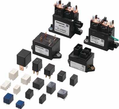
5 Automotive Relays Line Up Automotive Relays Contributing to the ever increasing need for versatility and innovation in car electronics with numerous relays for high voltage-cut-off and space savings. High Current High-Voltage Vertical (silent) EV 3A EV 2A EV 2A EV 8A EVS 6A EV 2A EV A (a) (a) (a) (a) (a) (a) (a) Special Solutions CW 4A Plug-In (2a) CB high capacity 7A CB standard 4A CM 3A (a) Mini ISO (a, c) Mini ISO (a, c) Micro ISO CV 2A CV -N 2A CA 2A to 3A 4 (a, c) Micro ISO (a) Micro ISO (a, b, c) JIS terminal

6 PC Board Silent Type CQ 2A TA 2A (c) (c) Twin Type CT-P 3A CT 2A TB 2A CJ 2A TE 2A TH 2A (cx2) (cx2) (cx2) (cx2) (cx2) (cx2, SMD) Single Type CB high capacity 7A CB standard 4A TG 3A CN-H 3A CN-M 3A Latching type available! (a) (a, c) (a, c) (a) (a, c) TC 3A TJ 3A CT-P 3A CT 2A TB 2A CJ 2A TE 2A (a, c, 2a c/2a latching) (c) (c) (c) (a, c) (c) (c) TH 2A CP-P 3A CP 2A CP-SMD 2A JJM 2A JJ-M Double make type 2A (c) (a, c) (a, c) (c) (a, c) (2a)(6Ax2)
7 Automotive Relays Recommended Applications Highly reliable relays that have proven record when it comes to safety, power train control, comfort and special vehicles. Safety Features Item Contact arrangement Coil voltage (DC) Headlights Tail lights Fog lamps (front and rear) Signal lights Windshield wipers Power Mirrors (incl. ones with heaters CT/CT-P c x 2 2V Twin CJ c x 2 2V TB c x 2 2V TE c x 2 2V CN-H a 2V TG a, c 2V CN-M a, c 2V CW 2a 2V JJ-M a, c 2V JJ-M Double make contact 2a 2V Single Latching type available! CT/CT-P c 2V TB a, c 2V TC a, c, Double make contact 2a latching 2a, c 2V TE c 2V CJ c 2V CP-P a, c 2V CP a, c 2V TJ c 2V CP c 2V SMD CN-M a, c 2V TH c, c x 2 2V Quiet CQ c 2V TA c 2V Mini ISO CB a, c Standard: 2V, 24V a high capacity: 2V Micro ISO CM a, c 2V, 24V CV-N a 2V 6
8 Power Train Control Windshield washers Defoggers Horns Blower fans Radiator fan motors Engine starter motors EPS (electrical power steering) Magnetic clutches ABS/TRC Semi-active suspension (with Di) (with Di) (with Di) (with Di) (with Di) 7
 Power sunroofs Power seats Lift gate Power window motor Keyless entry Door locks CT/CT-P c x 2 Twin CJ c x 2 TB c x 2 TE c x 2 CN-H a CN-M")
9 Automotive Relays Recommended Applications Highly reliable relays that have proven record when it comes to safety, power train control, comfort and special vehicles. Comfort Features Item Contact arrangement Coil voltage (DC) Power sunroofs Power seats Lift gate Power window motor Keyless entry Door locks CT/CT-P c x 2 Twin CJ c x 2 TB c x 2 TE c x 2 CN-H a CN-M a, c CW 2a JJ-M a, c JJ-M Double make contact 2a Single CT/CT-P TB c a, c 2V CJ c TE c CP-P a, c CP a, c TJ c CP c SMD CN-M a, c TH c, c x 2 Quiet CQ TA c c Mini ISO CB a, c Standard: 2V, 24V a high capacity: 2V Micro ISO CM a, c 2V, 24V CV-N a 2V 8
10 Slide door closer Car security Seat heaters Car stereo Interior lights Auto antennae Special vehicle Cruise control Motorcycles Forklifts 9


11 Automotive Relays Quality Control ISO/TS6949 Certificate of approval Our Automation Components Division has been accredited for ISO/TS6949. This covers our quality management system for an entire spectrum of automotive products from mechanical to semiconductor relays. Based on QS9, a quality management standard employed by the Big 3 United States automobile manufacturers, ISO/TS6949 is a quality management system standard that also incorporates the requirements put forth by the automobile industries of each European country. It calls for a comprehensive quality management system that includes CS, cost performance, and ongoing improvement. ISO4 IMDS (International Material Data System) Panasonic Electric Works is a registered corporation in the European automotive industry s International Material Data System. ISO/TS6949 ISO9 Certification Status Switching Device Division approved. Mechatro Device Division approved. Panasonic Electric Works Obihiro Co., Ltd. approved. Panasonic Electric Works (Thailand), Ltd. approved. Panasonic Electric Works Europe AG, German Factory approved. APQP Advanced Product Quality Planning & Control Plan DFMEA Design Potential Failure Mode & Effects Analysis PFMEA Process Potential Failure Mode & Effects Analysis CONTROL PLAN PROCESS CAPABILITY MSA Measurement Analysis etc. PPAP Production Part Approval Process CS Customer Satisfaction Global Network Panasonic Electric Works automotive relays meet higher level and ever more complex user needs through new product development, stable quality, speedy customer service, and production on a global scale. Europe Asia North America Germany Japan China Mexico Thailand Panasonic Industrial Device Taiko Shenzen Co, Ltd.
12 Automotive Relays Selector Chart
13 Automotive Relays Mechanical Relays Selector Chart Type = Popular Type (Picture scale: DIN A4) Features Switching current (: see data sheet) switching voltage Contact arrangement Coil voltage Coil power Between open contacts Breakdown voltage Between contact sets Contacts to coil Surge withstand voltage Mounting method (bottom view) Page Approvals PCB relays :2 CT Single:7.4 x 7.2 x 3.mm Twin:7.4 x 4 x 3.mm Super miniature size Twin ( Form C x 2) ACT2 layout = layout of 2 x ACT2 H-bridge type available (twin relay) Quiet operation RTIII (IP67) Pin in Paste (with vent hole) available : 2A (N.O.) A (N.C.) A 2A 6V DC c, c x 2 (DC) 2V 8mW Vrms Vrms PCB, PiP Ø 8 terminals Ø Ø Ø terminals :2 CT POWER Single:7.4 x 7.2 x 3.mm Twin:7.4 x 4 x 3.mm Super miniature size Twin ( Form C x 2) Footprint same as CT standard type 3A switching capacity (motor load) H-bridge type available (twin relay) RTIII (IP67) Pin in Paste (with vent hole) available : 3A (N.O.) A (N.C.) A 3A 6V DC c, c x 2 (DC) 2V mw Vrms Vrms PCB, PiP Ø 8 terminals Ø Ø Ø terminals :2 TB Single Print: 4 x 9.2 x 3.mm PiP: 4 x 9.2 x 4.mm Twin Print: 7.4 x 4 x 3.mm PiP: 7.4 x 4 x 4.mm Super miniature size Single ( Form A, Form C) Twin ( Form C x 2) H-bridge type available (twin relay) RTIII (IP67) Pin in Paste (with vent hole) available Lamp load type available : 2A (N.O.) A (N.C.) A 2A 6V DC a, c c x 2 (8 terminals) c x 2 ( terminals) (DC) 2V,44mW (for pick-up voltage max..v DC) 9mW (for pick-up voltage max. 6.V DC) 64mW (for pick-up voltage max. 7.7V DC) Vrms Vrms PCB, PiP 78 Twin type (8 terminal type) 4x.6 dia. 4x. dia. 3x.6 dia. 2x. dia. 4 c type
14 Automotive Relays Mechanical Relays Selector Chart Type = Popular Type (Picture scale: DIN A4) Features Switching current (: see data sheet) switching voltage Contact arrangement Coil voltage Coil power Between open contacts Breakdown voltage Between contact sets Contacts to coil Surge withstand voltage Mounting method (bottom view) Page Approvals :2 TE Single Print: 2 x 7.2 x 3.mm PiP: 2 x 7.2 x 4.mm Twin Print: 3.6 x 2 x 3.mm PiP: 3.6 x 2 x 4.mm Ultra small size Smallest in its class High capacity in a compact body Single ( Form C) Twin ( Form C x 2) H-bridge type available (twin relay) RTIII (IP67) Pin in Paste (with vent hole) available : 2A (N.O.) 2A A (N.C.) A 6V DC c, c x 2 (8 terminals) (DC) 2V,39mW (for pick-up voltage max..v DC) 9mW (for pick-up voltage max. 6.V DC) 6mW (for pick-up voltage max. 7.7V DC) Vrms Vrms PCB, PiP 93 Twin type (8 terminal type) 2x. dia x. dia. 2x. dia. 2x.6 dia. 3. c type x. dia..6 dia :2 CJ Ultra small size Twin ( Form C x 2) High capacity in a compact body H-bridge type available (twin relay) RTIII (IP67) Pin in Paste (with vent hole) available : 2A (N.O.) 2A A (N.C.) A 6V DC c, c x 2 (DC) 2V Standard: 8mW High sensitivity: 64mW Vrms Vrms PCB, PiP dia. 2-. dia dia dia. 4-. dia. 2-. dia Pin Print: 3.7 x 2.2 x 3.mm PiP: 3.7 x 2.2 x 3.8mm Pin Print: 4.4 x 2.2 x 3.mm PiP: 4.4 x 2.2 x 3.8mm :2 CP 4 x 3 x 9.mm Very low profile High capacity 24V DC type available on request RTIII (IP67) : 2A (N.O.) 2A A (N.C.) A 6V DC a, c (DC) 2V, 24V 64mW Vrms Vrms PCB Ø (R).4 4. CP POWER :2 4 x 3 x 9.mm Very low profile High capacity type: 4A maximum carrying current Improved heat conduction thanks to additional pin Layout is downward compatible to CP RTIII (IP67) Pin in Paste (with vent hole) available : 2A (N.O.) 2A A (N.C.) A 6V DC a, c (DC) 2V 4mW 64mW Vrms Vrms PCB dia. (hole) (R.4) :2 CP (SMD) 4 x 3 x.mm Very low profile High capacity RTIII (IP67) : 2A (N.O.) 2A A (N.C.) A 6V DC c (DC) 2V 64mW Vrms Vrms SMT
15 Automotive Relays Mechanical Relays Selector Chart Type = Popular Type (Picture scale: DIN A4) Features Switching current (: see data sheet) switching voltage Contact arrangement Coil voltage Coil power Between open contacts Breakdown voltage Between contact sets Contacts to coil Surge withstand voltage Mounting method (bottom view) Page Approvals :2 TJ x 6 x.2mm Compact flat type (height:.2mm) High capacity switching Thermal resistant type RTIII (IP67) : 3A (N.O.) A (N.C.) A 3A 6V DC c (DC) 2V 4mW Vrms Vrms PCB.7 7 4xR (.8) :2 CQ Very quiet operation Terminal layout identical to JJM RTIII (IP67) : 2A (N.O.) 2A A (N.C.) 6V DC c (DC) 2V 64mW Vrms Vrms PCB Ø. 7 x 3 x 6.6mm A 2..2 :2 TA 9.8 x 7 x 4mm Very quiet operation Flat type RTIII (IP67) : 2A (N.O.) A (N.C.) A 2A 6V DC c (DC) 2V 64mW (for pick-up voltage max. 7.7V DC) 9mW (for pick-up voltage max. 6.V DC) Vrms Vrms PCB 74 x.6 dia. 8.2 :2 CN-M, x x 4.4mm Space-saving design High switching capacity (up to 3A) SMD type available RTIII (IP67) Pin in Paste (with vent hole) available : 3A (N.O.) 2A (N.C.) 3A 2A 6V DC a, c (DC) 2V 64mW Vrms Vrms PCB, SMT x. dia..9 x Best space savings in its class : 6V DC a (DC) 2V 4mW CN-H Substitute for Micro-ISO relay :2 3A Low operating power type High current-carrying capacity RTIII (IP67) 7 x.6 x 8.3mm (for pick-up voltage max. 6.V DC) 64mW (for pick-up voltage max..v DC) Vrms Vrms PCB dia. (hole) dia. (hole) :2 TG 7.8 x 2.6 x 8mm Large capacity switching despite small size. Substitute for micro ISO relays Low operating power type RTIII (IP67) : 3A (N.O.) A (N.C.) A 3A 6V DC a, c (DC) 2V 64mW (for pick-up voltage max. 6.V DC) 4mW (for pick-up voltage max. 7.V DC) Vrms Vrms PCB 98 a type x.6 dia. c type x.6 dia
16 Automotive Relays Mechanical Relays Selector Chart Type = Popular Type (Picture scale: DIN A4) Features Switching current (: see data sheet) switching voltage Contact arrangement Coil voltage Coil power Between open contacts Breakdown voltage Between contact sets Contacts to coil Surge withstand voltage Mounting method (bottom view) Page Approvals TC :2 Print: 7.8 x 3 x 6.mm PiP: 7.8 x 3 x 6.4mm Large capacity switching despite small size Substitute for micro ISO relays Latching type available High heat resistant type available Pin in Paste types available : 3A (N.O.) A (N.C.) A 3A 6V DC a, c, 2a 2a 2 coil latching (DC) 2V,39mW (for pick-up voltage max. 6.V DC) 9mW (for pick-up voltage max. 7.V DC) 64mW (for pick-up voltage max. 7.V DC),92mW (2 coil latching type) Vrms Vrms PCB, PiP 86 a standard type x.6 dia..8 c/2a standard type x.6 dia..8 2a latching type 3x. dia x.6 dia..8 :2 TH Single: x 2 x 8.8mm Twin: 2.6 x 2 x 8.8mm Ultra compact flat type SMD monting type: 8.8mm High switching capacity (up to 2A) Single ( Form C) Twin ( Form C x 2) : 2A (N.O.) A (N.C.) A 2A 6V DC c, c x 2 ( terminals) (DC) 2V 9mW (for pick-up voltage max. 6.V DC) 6mW (for pick-up voltage max. 7.7V DC) Vrms Vrms SMT 3 Twin type ( terminal type) 3.8 6x x2 c type x x :2 JJM Compact size Best-selling, familiar blinker sound RTIII (IP67) : 2A (N.O.) 2A A (N.C.) 6V DC a, c (DC) 2V 64mW Vrms Vrms PCB Ø.. Ø. x 2 x 3.9mm A 2..2 :2 JJM-DM. x 2 x 3.9mm Small size Double make contact arrangement Terminal layout compatible to JJM RTIII (IP67) : 2 x 6A 6V DC Double make contact 6A 6A (DC) 2V mw Vrms Vrms PCB Ø.. Ø
17 Automotive Relays Mechanical Relays Selector Chart Type = Popular Type (Picture scale: DIN A4) Features Switching current (: see data sheet) switching voltage Contact arrangement Coil voltage Coil power Between open contacts Breakdown voltage Between contact sets Contacts to coil Surge withstand voltage Mounting method (bottom view) Page Approvals Plug-in relays :2 CA 2. x 4.4 x 37mm Small size Direct plug-in RTIII (IP67) : 2A (a,.4w type) 2A 3A (a,.8w type) 2A (b, c) 2A 3A V DC (c - 2V DC type) 6V DC (a, b - 2V DC type) 3V DC (c - 24V DC type) a, b, c (DC) 2, 24V 8mW 4mW (type S) Vrms Vrms Plug-in 2 9. Sealed with epoxy resin 6 9 a, b :2 CM Small substitute for Mini-ISO relay Micro-ISO terminal type RTIII (IP67) available : 3A (N.O.) 2A (N.C.) 3A 6V DC (2V DC type) 32V DC (24V DC type) a, c (DC) 2, 24V mw (2V DC type) 8mW (24V DC type) Vrms Vrms PCB (24V), Plug-in A 2 x x 22mm :2 CV Low profile 2A Micro-ISO terminal type RTIII (IP67) : 2A (N.O.) 2A 6V DC a, c (DC) 2V 8mW Vrms Vrms Plug-in x x.7mm A (N.C.) A Including resistor type also available :2 CV-N 22. x x.7mm Low profile Low temperature rise Low sound pressure level RTIII (IP67) available : 2A (N.O.) 2A A (N.C.) A 4V DC a, c (DC) 2V 8mW Vrms Vrms Plug-in 32 NO Including resistor type also available :2 CB 4A switching current at 8 C Mini-ISO type terminals High shock resistance High thermal resistance Form A available with 7A switching current Broad lineup RTIII (IP67) available : 7A (N.O. H type) 4A (a, c N.O.) 3A (c N.C.) 4A 7A 6V DC (2V DC type) 32V DC (24V DC type) a, c (DC) 2, 24V 4mW (2V DC type) 8mW (24V DC type) 8mW (2V DC, H type) Vrms Vrms PCB, Plug-in (PCB standard type) 26 x 22 x 2mm 3A 2 2
18 ) Automotive Relays Mechanical Relays Selector Chart Type = Popular Type (Picture scale: DIN A4) Features Switching current (: see data sheet) switching voltage Contact arrangement Coil voltage Coil power Between open contacts Breakdown voltage Between contact sets Contacts to coil Surge withstand voltage Mounting method (bottom view) Page Approvals High current/ High voltage relays EV 6 versions available:, 2, :8 8, 2, 2A, 3A DC type with sealed capsule for electric and hybrid vehicles Compact size 66.8 x 49.7 x 37.9mm Small arcing space required 78 x 4 x 48.mm thanks to blow-out magnets Safety construction High contact reliability 82.8 x 4 x 79mm 7. x 4 x 8mm : A (a) A 2A (a) 8A (a) 2A 2A (a) 8A 2A 4V DC a (DC) 2, 24V Stable: 24mW (A, 2/24V) 39mW (2A, 2V) 42mW (8A/2A, 2/24V) 6mW (2A, 2/24V) 36mW (3A, 2V) 38mW (3A, 24V) Inrush: 37.9W (3A, 2V) 44.4W (3A, 24V) 2Vrms 2Vrms Lead wire (2A) Faston terminal (A, 2A) 4 2A (a) 9 x 4 x 86.4mm 2A x 63 x 7mm 3A (a) 3A :4 EV QUIET 76 x 36 x 72.3mm DC type with sealed capsule, mainly for hybrid vehicles Very quiet operation Small size and light weight Small arcing space required thanks to blow-out magnets Safety construction High contact reliability Standard type for horizontal mounting available : 6A (a) 6A 4V DC a (DC) 2V 4mW Vertical: 2Vrms Horizontal: 2Vrms Vertical: 2Vrms Horizontal: 2Vrms Vertical type: lead wire Horizontal type: Faston terminal 4 77 x 67.8 x 37.7mm :4 EV SWITCH High performance with capsule contact technology High carrying current performance Safety function : 8A (a) 8A 4V DC a (DC) 2V 2Vrms 2Vrms Screw terminal 6 Lever OFF Interlock button OFF (7.2) (89 ) Position of Lever-OFF M (3.) bolt collar 26±. 28.8± 8 ( lever height: x 34.6 x 4.3mm M bolt ± ±.6 (4.3) :2 CW 32 x 8 x 26mm Ideal relay for high output,3- phase motors (Electric Power Steering) High cut-off current capability and high carrying current RTIII (IP67) : 4V DC 2a (DC) 2V 4mW Vrms Vrms Welding 42 2A 22 23
19
20 Automotive PCB Relays
21 CJ (ACJ) PACT SLIM TWIN AND SINGLE TYPE AUTOMOTIVE RELAY CJ RELAYS (ACJ) FEATURES It is extremely compact at approx. 2/3 the size of previous products. Compared to our previous miniature type CT relay, both the Form C and -pin and 8-pin twin types take up approx. two-thirds the space and volume. This makes them ideal for relay unit miniaturization. Compact and high-capacity 2 A load switching High capacity control is possible while being compact and capable of motor lock load switching at 2 A, 4 V DC. Pin in Paste* compatible model added Models compatible with the recently increasing Pin in Paste technique (reflow solder mounting) have been added. Pin in Paste compatible models are the flux tight type. * The Pin in Paste method may sometimes be referred to as THR (Through-hole Reflow). Environmental protection specifications Cadmium-free contacts and use of leadfree solder are standard. Environmental pollutants are not used. TYPICAL APPLICATIONS Powered windows Automatic door locks Electrically powered mirrors Powered sunroofs Powered seats Lift gates Smart J/B related products, etc. ORDERING INFORMATION Contact arrangement : Form C 2: Form C 2 (8 terminal) : Form C 2 ( terminal) : 6. V DC 2: 7.2 V DC Coil voltage, DC 2: 2 V Mounting type Nil: Standard type P: Pin in Paste available type TYPES Contact arrangement Form C Form C 2 (8 terminal) Form C 2 ( terminal) ACJ Nominal coil voltage 2 V DC (at 2 C 68 F) Standard type Standard packing; Carton (tube): 7 pcs.; Case: 2,8 pcs. ( Form C), Carton (tube): 4 pcs.; Case:, pcs. (8 terminal), Carton (tube): 3 pcs.; Case:,4 pcs. ( terminal) 26 ds_62_en_cj: 3D Part No. Pin in Paste type 6. V DC (Initial) ACJ2 ACJ2P 7.2 V DC (Initial) ACJ22 ACJ22P 6. V DC (Initial) ACJ22 ACJ22P 7.2 V DC (Initial) ACJ222 ACJ222P 6. V DC (Initial) ACJ2 ACJ2P 7.2 V DC (Initial) ACJ22 ACJ22P
22 RATING. Coil data Nominal coil voltage 2 V DC (at 2 C 68 F) 7.2 V DC (Initial) 6. V DC (Initial) (at 2 C 68 F). V DC (Initial).8 V DC (Initial) Nominal operating current [ %] (at 2 C 68 F) * Other usable voltage range types are also available. Please contact us for details. Coil resistance [ %] (at 2 C 68 F) Nominal operating power (at 2 C 68 F) CJ (ACJ) Usable voltage range* 3.3 ma mw to 6 V DC 66.7 ma 8 8 mw 9 to 6 V DC 2. Specifications Characteristics Item Specifications Arrangement Form C, Form C 2 Contact Contact resistance (Initial) N.O.: Typ7m, N.C.: Typm (By voltage drop 6 V DC A) Contact material Ag alloy (Cadmium free) Protective construction Standard type: Sealed type Pin in Paste type: Flux tight type Nominal switching capacity (resistive load) N.O.: 2A 4V DC, N.C.: A 4V DC Rating carrying current (4V DC) N.O.: 2 A for hour, 3 A for 2 minutes (at 2 C 68 F) (when coil powered on one side) Nominal operating power 64 mw (for pick-up voltage max. 7.2 V DC), 8 mw (for pick-up voltage max. 6. V DC) switching capacity (resistive load)* A 4V DC Initial insulation resistance M (at V DC, Measurement at same location as Breakdown voltage section.) Breakdown Between open contacts Vrms for min. (Detection current: ma) Electrical voltage (Initial) Between contacts and coil Vrms for min. (Detection current: ma) characteristics Operate time (at nominal voltage) ms (at 2 C 68 F, excluding contact bounce time) (Initial) Release time (at nominal voltage) ms (at 2 C 68 F, excluding contact bounce time) (Initial) Shock Functional m/s 2 {G} (Half-wave pulse of sine wave: ms; detection time: s) resistance Destructive, m/s 2 {G} (Half-wave pulse of sine wave: 6ms) Mechanical characteristics Functional Hz to Hz, 44.m/s 2 {4.G} (Detection time: s) Vibration resistance Hz to Hz, 44.m/s Destructive {4.G} Time of vibration for each direction; X, Y direction: 2 hours, Z direction: 4 hours Mechanical 7 (at 2 cpm) [Standard type] <Resistive load> (at nominal switching capacity, operating frequency: s ON, 9s OFF) <Motor load> N.O. side: 2 : at 2 A (inrush), A (steady), 4 V DC; : at 2 A 4 V DC (Motor lock) Expected life N.C. side: 2 Electrical : at 2 A 4 V DC (brake) (Operating frequency:.s ON, 9.s OFF) [Pin in Paste type] <Resistive load> (at nominal switching capacity, operating frequency: s ON, 9s OFF) <Motor load> N.O. side: : at 2 A (inrush), A (steady), 4 V DC; 4 : at 2 A 4 V DC (Motor lock) N.C. side: : at 2 A 4 V DC (brake) (Operating frequency:.s ON, 9.s OFF) Conditions Mass Conditions for operation, transport and storage* 2 operating speed Ambient temperature: 4 C to +8 C 4 F to +8 F Humidity: % R.H. to 8% R.H. (Not freezing and condensing at low temperature) 6 cpm (at nominal switching capacity) Form C type: approx. 3. g.2 oz, Twin type: approx. 6. g.23 oz Notes: *. This value can change due to the switching frequency, environmental conditions, and desired reliability level, therefore it is recommended to check this with the actual load. *2. The upper operation ambient temperature limit is the maximum temperature that can satisfy the coil temperature rise value. Refer to Usage ambient condition on page 78. Please inquire if you will be using the relay in a high temperature atmosphere ( C 23 F). *3. Depends on connection conditions. Also, this does not guarantee repeated switching. We recommend that you confirm operation under actual conditions. If the relay is used continuously for long periods of time with coils on both sides in an energized condition, breakdown might occur due to abnormal heating depending on the carrying condition. Therefore, please inquire when using with a circuit that causes an energized condition on both sides simultaneously. Automotive ds_62_en_cj: 3D 27
23 CJ (ACJ) REFERENCE DATA.-() Coil temperature rise (at room temperature) Sample: ACJ22, 3pcs Measured portion: Inside the coil Contact carrying current: A, A, 2A Ambient temperature: 2 C 77 F Temperature rise, C (when coil powered on one side) Coil applied voltage, V 2A A A.-(2) Coil temperature rise (at 8 C 8 F) Sample: ACJ22, 3pcs Measured portion: Inside the coil Contact carrying current: A, A, 2A Ambient temperature: 8 C 8 F Temperature rise, C (when coil powered on one side) Coil applied voltage, V 2A A A.-(3) Coil temperature rise (at room temperature) Sample: ACJ222, 3pcs Measured portion: Inside the coil Contact carrying current: A, A, 2A Ambient temperature: 2 C 77 F Temperature rise, C (when coil powered on one side) Coil applied voltage, V 2A A A.-(4) Coil temperature rise (at 8 C 8 F) Sample: ACJ222, 3pcs Measured portion: Inside the coil Contact carrying current: A, A, 2A Ambient temperature: 8 C 8 F.-() Coil temperature rise (at room temperature) Sample: ACJ22, 3pcs Measured portion: Inside the coil Contact carrying current: A, A, 2A Ambient temperature: 2 C 77 F.-(6) Coil temperature rise (at 8 C 8 F) Sample: ACJ22, 3pcs Measured portion: Inside the coil Contact carrying current: A, A, 2A Ambient temperature: 8 C 8 F 2 (when coil powered on one side) 2 (when coil powered on one side) 2 (when coil powered on one side) Temperature rise, C A A A Temperature rise, C A A A Temperature rise, C A A A Coil applied voltage, V Coil applied voltage, V Coil applied voltage, V 2.-() Ambient temperature and operating voltage range 2.-(2) Ambient temperature and operating voltage range 3.-() Distribution of pick-up and drop-out voltage Sample: ACJ22, pcs. Ambient temperature: Room temperature Coil applied voltage, VDC 2 Operating voltage range : ACJ2, ACJ2P ACJ22, ACJ22P ACJ2, ACJ2P (cold start) Ambient temperature, C Coil applied voltage, VDC 2 Operating voltage range : ACJ22, ACJ22P ACJ222, ACJ222P ACJ22, ACJ22P (cold start) Ambient temperature, C 2 Quantity, n Voltage, V Pick-up voltage Drop-out voltage 28 ds_62_en_cj: 3D
24 3.-(2) Distribution of pick-up and drop-out voltage Sample: ACJ222, pcs. Ambient temperature: Room temperature 4 4.-() Distribution of operate and release time Sample: ACJ22, pcs. Ambient temperature: Room temperature 4 *Without diode Operate time Release time CJ (ACJ) 4.-(2) Distribution of operate and release time Sample: ACJ222, pcs. Ambient temperature: Room temperature 4 *Without diode Operate time Release time Quantity, n 3 Quantity, n 3 Quantity, n Voltage, V Time, ms Time, ms.-() Electrical life test (Motor free) Sample: ACJ222, 3pcs Load: Inrush current: 2A/Steady current: A, Power window motor actual load (free condition) Tested voltage: 4V DC Switching frequency: ON.s, OFF 9.s Switching cycle: 2 Ambient temperature: Room temperature Circuit No. side No. 2 side.s.s s s ( cycle) 4V DC M Change of pick-up and drop-out voltage Pick-up and drop-out voltage, V Contact welding: time Miscontact: time No. of operations, 4 2 X X Change of contact resistance Contact resistance, m 4 3 N.C. side N.O. side 2 X(N.C.) X(N.O.) 2 No. of operations, 4 Load current waveform Inrush current: 2A, Steady current: 6A, Brake current: 3A P/W motor (free condition) Automotive A ms ds_62_en_cj: 3D 29
25 CJ (ACJ).-(2) Electrical life test (Motor lock) Sample: ACJ222, 3pcs Load: Steady current: 2A, Power window motor actual load (lock condition) Tested voltage: 4V DC Switching frequency: ON.s, OFF 9.s Switching cycle: Ambient temperature: Room temperature Circuit No. side No. 2 side.s.s s s ( cycle) 4V DC M Change of pick-up and drop-out voltage Pick-up and drop-out voltage, V Contact welding: time Miscontact: time No. of operations, 4 X X Change of contact resistance Contact resistance, m 4 3 N.C. side N.O. side 2 X(N.O.) X(N.C.) No. of operations, 4 P/W motor (lock condition) Load current waveform Current value: 2A A ms DIMENSIONS (mm inch) Download CAD Data from our Web site.. Twin type (8-pin) CAD Data ±.3.3±.2 External dimensions A* Pre-soldering (all terminals) Sealed by epoxy resin * Dimensions (thickness and width) of terminal is measured before pre-soldering. Intervals between terminals is measured at A surface level. Dimension: Tolerance mm.39 inch:..4 to 3mm.39 to.8 inch:.2.8 3mm.8 inch:.3.2 PC board pattern (Bottom view) dia. 2.9 dia dia dia. 2.9 dia dia..4.4 Tolerance:..4 Schematic (Bottom view) NC NO 3 ds_62_en_cj: 3D
26 2. Twin type (8-pin) Pin in Paste type CAD Data ±.3.3±.2 External dimensions A* Pre-soldering (all terminals) Sealed by epoxy resin * Dimensions (thickness and width) of terminal is measured before pre-soldering. Intervals between terminals is measured at A surface level Vent Dimension: Tolerance mm.39 inch:..4 to 3mm.39 to.8 inch:.2.8 3mm.8 inch:.3.2 CJ (ACJ) PC board pattern (Bottom view) dia. 2.9 dia dia dia. 2.9 dia dia..4.4 Tolerance:..4 Schematic (Bottom view) NC NO 3. Twin type (-pin) Standard type CAD Data External dimensions PC board pattern (Bottom view) 4. dia. 4. dia. 4.9 dia dia. 2. dia. 2.9 dia A surface level Pre-soldering (all terminals) Sealed by epoxy resin * Dimensions (thickness and width) of terminal is measured before pre-soldering. Intervals between terminals is measured at A surface level. Dimension: Tolerance mm.39 inch:..4 to 3mm.39 to.8 inch:.2.8 3mm.8 inch: Tolerance:..4 Schematic (Bottom view) NC NO NC NO Automotive 4. Twin type (-pin) Pin in Paste type CAD Data External dimensions PC board pattern (Bottom view) 4. dia. 4. dia. 4.9 dia dia. 2. dia. 2.9 dia. ds_62_en_cj: 3D A surface level Pre-soldering (all terminals) Sealed by epoxy resin * Dimensions (thickness and width) of terminal is measured before pre-soldering. Intervals between terminals is measured at A surface level. Vent Dimension: Tolerance mm.39 inch:..4 to 3mm.39 to.8 inch:.2.8 3mm.8 inch: Tolerance:..4 Schematic (Bottom view) NC NO NC NO
27 CJ (ACJ). Slim Form C Standard type CAD Data External dimensions PC board pattern (Bottom view) 2. dia. 2.9 dia. 2. dia dia Pre-soldering (all terminals) A surface level Sealed by epoxy resin * Dimensions (thickness and width) of terminal is measured before pre-soldering. Intervals between terminals is measured at A surface level Dimension: Tolerance mm.39 inch:..4 to 3mm.39 to.8 inch:.2.8 3mm.8 inch: dia..9 dia. Tolerance:..4 Schematic (Bottom view) NC NO 6. Slim Form C Pin in Paste type CAD Data External dimensions PC board pattern (Bottom view) 2. dia. 2.9 dia. 2. dia dia Pre-soldering (all terminals) A surface level Sealed by epoxy resin * Dimensions (thickness and width) of terminal is measured before pre-soldering. Intervals between terminals is measured at A surface level. Vent Dimension: Tolerance mm.39 inch:..4 to 3mm.39 to.8 inch:.2.8 3mm.8 inch: dia..9 dia. Tolerance:..4 Schematic (Bottom view) NC NO NOTES Assembly and cleaning conditions for Pin-in-Paste type ) Example of the recommended Cautions for mounting conditions for automated assembly is Temperature rise of relay itself may vary shown below. according to the mounting level or the Temperature profile during reflowsoldering (Recommended) Therefore, please set the temperature of heating method of reflow equipment. soldering portion of relay terminal and the T3 top surface of the relay case not to T2 exceed the above mentioned soldering condition. It is recommended to check the T temperature rise of each portion under actual mounting condition before use. 2) Cleaning or coating should be avoided. Because Pin-in-Paste type is not a sealed type. Also, use caution for avoiding penetration of soldering flux into the interior of the relay. t t2 T = to 8 C 32 to 36 F T2 = 23 C 446 F or more T3 = Less than 26 C F t = 6 to 2 sec. t2 = Less than 4 sec. 32 ds_62_en_cj: 3D
28 EXAMPLE OF CIRCUIT Forward/reverse control circuits of DC motor (for Form C 2 (8 terminal) type) CJ (ACJ) 2 V DC NO NC M NO NC SW A SW B M : Power window motor For Cautions for Use, see Relay Technical Information (page 66). Automotive ds_62_en_cj: 3D 33
29 CN-H (ACNH3) HIGH LOAD RELAY FOR SMART J/B CN-H RELAYS (ACNH) FEATURES Best space savings in its class Large capacity switching despite small size. Can replace micro ISO terminal type relays. Terminals for PC board pattern designs are easily allocated. Sealed type TYPICAL APPLICATIONS Head lamp, Fog lamp, Fan motor, EPS, Defogger, Seat heater, etc. ORDERING INFORMATION Contact arrangement 3: Form A :.V DC 2: 6.V DC Coil voltage (DC) 2: 2V ACNH TYPES Contact arrangement Nominal coil voltage (at 2 C 68 F) Part No. 6. V DC (Initial) ACNH322 Form A 2V DC. V DC (Initial) ACNH32 Standard packing; Carton (tube): pcs.; Case:, pcs. RATING. Coil data Nominal coil voltage 2 V DC (at 2 C 68 F) 6. V DC (Initial). V DC (Initial) (at 2 C 68 F). V DC (Initial).8 V DC (Initial) Nominal operating current [ %] (at 2 C 68 F) Coil resistance [ %] (at 2 C 68 F) Nominal operating power (at 2 C 68 F) 37. ma 32¾ 4 mw 3.3 ma 22¾ 64 mw Usable voltage range to 6 V DC 34 ds_629_en_cnh: 3J
30 2. Specifications Characteristics Item Specifications Contact Rating Electrical characteristics Mechanical characteristics Expected life Conditions Mass Arrangement CN-H (ACNH3) Notes: *. This value can change due to the switching frequency, environmental conditions, and desired reliability level, therefore it is recommended to check this with the actual load. REFERENCE DATA Form A Contact resistance (Initial) Typm (By voltage drop 6 V DC A) Contact material Nominal switching capacity (resistive load) carrying current Continuous carrying current Nominal operating power switching capacity (resistive load)* Insulation resistance (Initial) Breakdown voltage Between open contacts (Initial) Between contacts and coil Operate time (at nominal voltage) Release time (at nominal voltage) Functional Shock resistance Destructive Functional Vibration resistance Destructive Mechanical Electrical Conditions for operation, transport and storage -(). Coil temperature rise Sample: ACNH322, 3pcs Measured portion: Inside the coil Contact carrying current: A, 2A, 3A Ambient temperature: 2 C 77 F Ag alloy (Cadmium free) 3A 4V DC <4mW> 3A/ h, 4A/2 min. at 2 C 68 F 3A/ h, 4A/2 min. at 8 C 8 F 2A/ h, 3A/2 min. at C 23 F <64mW> 3A/ h, 4A/2 min. at 2 C 68 F 2A/ h, 3A/2 min. at 8 C 8 F 2A/ h, 3A/2 min. at C 23 F 2A 4V DC (4mW) at C 23 F, A 4V DC (64mW) at C 23 F 4 mw (for pick-up voltage max. 6. V DC), 64 mw (for pick-up voltage max.. V DC) A 4V DC M (at V DC, Measurement at same location as Breakdown voltage section.) Vrms for min. (Detection current: ma) Vrms for min. (Detection current: ma) ms (at 2 C 68 F, excluding contact bounce time) (Initial) ms (at 2 C 68 F) (Initial) (without protective element) m/s 2 {G} (Half-wave pulse of sine wave: ms; detection time: s), m/s 2 {G} (Half-wave pulse of sine wave: 6ms) Hz to Hz, 44.m/s 2 {4.G} (Detection time: s) Hz to Hz, 44.m/s 2 {4.G} Time of vibration for each direction; X, Y direction: 2 hours, Z direction: 4 hours 7 (at 2 cpm) <Resistive load> (at nominal switching capacity, operating frequency: s ON, s OFF) <Motor load> 3 (at inrush 84 A, steady 8 A, 4 V DC operating frequency: ON 2s, OFF s) <Lamp load> 2 (at inrush 84 A, steady 2 A, 4 V DC operating frequency: ON s, OFF 4s) Ambient temperature: 4 C to + C 4 F to +23 F Humidity: 2% R.H. to 8% R.H. (Not freezing and condensing at low temperature) Approx. 9 g.32 oz -(2). Coil temperature rise Sample: ACNH322, 3pcs Measured portion: Inside the coil Contact carrying current: A, 2A Ambient temperature: C 23 F 2. Ambient temperature and operating voltage range Automotive Temperature rise, C A 2A A Temperature rise, C A A Coil applied voltage, VDC : ACNH322 (cold start) Operating voltage range : ACNH32 (cold start) Coil applied voltage, V Coil applied voltage, V Ambient temperature, C ds_629_en_cnh: 3J 3
31 CN-H (ACNH3) 3-(). Distribution of pick-up and drop-out voltage Sample: ACNH322, 2pcs. 3-(2). Distribution of pick-up and drop-out voltage Sample: ACNH32, 2pcs. 2 2 Quantity, n Quantity, n Voltage, V Voltage, V 4-(). Distribution of operate and release time Sample: ACNH322, 2pcs. 4-(2). Distribution of operate and release time Sample: ACNH32, 2pcs. 2 Operate time Release time 2 Operate time Release time Quantity, n Quantity, n Time, ms Time, ms. Electrical life test (Resistive load) Sample: ACNH322, 6pcs. Load: Resistive load (NO side: 3A 4V DC) Operating frequency: ON s, OFF s Ambient temperature: Room temperature Circuit: 4V DC Change of pick-up and drop-out voltage Pick-up and drop-out voltage, V Contact welding: time Miscontact: time x x Change of contact resistance 3 Contact resistance, mω 2 2 x No. of operations, 4 No. of operations, 4 6-(). Electrical life test (Motor load) Sample: ACNH322, 3pcs. Load: inrush: 84A/steady: 8A, radiator fan actual load (motor free) Operating frequency: ON 2s, OFF s Ambient temperature: C 23 F Circuit: 4V DC M Change of pick-up and drop-out voltage Pick-up and drop-out voltage, V Contact welding: time Miscontact: time x x Change of contact resistance 3 Contact resistance, mω 2 2 x No. of operations, 4 3 No. of operations, ds_629_en_cnh: 3J
32 6-(2). Electrical life test (Lamp load) Sample: ACNH322, 6pcs. Load: 6W 2, inrush: 84A/steady: 2A Operating frequency: ON s, OFF 4s Ambient temperature: Room temperature Circuit: 4V DC 6W 6W Change of pick-up and drop-out voltage Pick-up and drop-out voltage, V Contact welding: time Miscontact: time No. of operations, 4 x x 2 Change of contact resistance Contact resistance, mω CN-H (ACNH3) No. of operations, 4 x 2 DIMENSIONS (mm inch) Download CAD Data from our Web site. CAD Data External dimensions PC board pattern (Bottom view) dia. (hole) dia. (hole) dia. (hole) dia. (hole) +..7 dia. (hole) dia. (hole) A Pre-soldering Schematic (Bottom view) Coil..27 Tolerance:..4 NO * Dimensions (thickness and width) of terminal is measured before pre-soldering. Intervals between terminals is measured at A surface level. Dimension: General tolerance mm.39 inch:..4 to 3mm.39 to.8 inch:.2.8 3mm.8 inch:.3.2 Coil Automotive NOTES Usage, transport and storage conditions ) Ambient temperature, humidity, and atmospheric pressure during usage, transport, and storage of the relay: () Temperature: 4 to + C 4 to +23 F (2) Humidity: 2 to 8% RH (Avoid freezing and condensation.) (3) Atmospheric pressure: 86 to 6 kpa The humidity range varies with the temperature. Use within the range indicated in the graph below. (Temperature and humidity range for usage, transport, and storage) 2 8 (Avoid freezing when used at temperatures lower than C 32 F) Tolerance range Humidity, %RH (Avoid condensation when used at temperatures higher than C 32 F) Temperature, C F +23 For Cautions for Use, see Relay Technical Information (page 66). ds_629_en_cnh: 3J 37
33 CN-M (ACNM) MIDDLE LOAD RELAY FOR SMART J/B CN-M RELAYS (ACNM) FEATURES Best space savings in its class. Compact and high-capacity 3A load switching. Full line up (High heat-resistant type and SMD type) Terminals for PC board pattern designs are easily allocated. TYPICAL APPLICATIONS Defogger, Seat heater, Head lamp, Fog lamp, Fan motor, etc. ORDERING INFORMATION ACNM Contact arrangement* : Form C 3: Form A : Form C high heat-resistant type 7: Form A high heat-resistant type : 7.2V DC Coil voltage (DC) 2: 2V Terminal shape Nil: PC board terminal SA: Surface-mount terminal Packing style* 2 Nil: Tube packing X: Tape and reel packing (Reverse NO terminal direction in pull-out direction) Z: Tape and reel packing (Normal NO terminal direction in pull-out direction) Notes: *. Surface-mount terminal type is available in high heat-resistant type only. *2. Tube packing: PC board terminal type only Tape and reel packing: Surface-mount type only TYPES. PC board terminal type Contact arrangement Nominal coil voltage Part No. Standard type High heat-resistant type Form A ACNM32 ACNM72 2V DC Form C ACNM2 ACNM2 Standard packing; Carton (tube): pcs.; Case:, pcs. 2. Surface-mount terminal type Contact arrangement Form A Form C Nominal coil voltage 2V DC Part No. High heat-resistant type ACNM72SAX ACNM72SAZ ACNM2SAX ACNM2SAZ Standard packing; Carton (tape and reel): 2 pcs.; Case: 6 pcs. Notes: *.Surface-mount terminal type is available in high heat-resistant type only. *2.An X at the end of the part number indicates, for tape and reel packing, reverse NO terminal direction in pull-out direction. A Z at the end of the part number indicates, for tape and reel packing, normal NO terminal direction in pull-out direction. 38 ds_622_en_cnm: 3J
34 RATING. Coil data Nominal coil voltage 2 V DC 2. Specifications (at 2 C 68 F) 7.2 V DC (Initial) (at 2 C 68 F). V DC (Initial) Nominal operating current [ %] (at 2 C 68 F) Coil resistance [ %] (at 2 C 68 F) Nominal operating power (at 2 C 68 F) CN-M (ACNM) Usable voltage range 3.3 ma mw to 6 V DC Characteristics Item Specifications Contact Rating Electrical characteristics Mechanical characteristics Expected life Conditions Unit weight Arrangement Form A, Form C Contact resistance (Initial) Typical m (By voltage drop 6 V DC A) Contact material Nominal switching capacity (resistive load) carrying current (at 4V DC) Nominal operating power switching capacity (resistive load)* Insulation resistance (Initial) Breakdown Between open contacts voltage (Initial) Between contacts and coil Operate time (at nominal voltage) Release time (at nominal voltage) Functional Shock resistance Destructive Functional Vibration resistance Destructive Mechanical Electrical Conditions for operation, transport and storage Ag alloy (Cadmium free) N.O.: 3A 4V DC, N.C.: A 4V DC N.O. 3A/ h, 4A/2 min. at 2 C 68 F 2A/ h, 3A/2 min. at 8 C 8 F 2A/ h, 3A/2 min. at C 23 F (High heat-resistant type) N.C. 2A/ h, 3A/2 min. at 2 C 68 F 2A/ h, 2A/2 min. at 8 C 8 F A/ h, 2A/2 min. at C 23 F (High heat-resistant type) 64 mw A 2V DC M (at V DC) Vrms for min. (Detection current: ma) Vrms for min. (Detection current: ma) ms (at 2 C 68 F, excluding contact bounce time) (Initial) ms (at 2 C 68 F, excluding contact bounce time) (Initial) (without diode) m/s 2 {G} (Half-wave pulse of sine wave: ms; detection time: s), m/s 2 {G} (Half-wave pulse of sine wave: 6ms) Hz to Hz, 44.m/s 2 {4.G} (Detection time: s) Hz to Hz, 44.m/s 2 {4.G} Time of vibration for each direction; X, Y direction: 2 hours, Z direction: 4 hours 7 (at 2 cpm) <Resistive load> (At nominal switching capacity, operating frequency: s ON, 2s OFF) <Motor load> 2 : at 8 A (inrush), 6 A (steady), 4 V DC (Operating frequency: 2s ON, 6s OFF) <Lamp load> : at 84 A (inrush), 2 A (steady), 4 V DC (Operating frequency: s ON, 4s OFF) Standard type; Ambient temp: 4 C to +8 C 4 F to +8 F, Humidity: to 8% R.H. High heat-resistant type; Ambient temp: 4 C to + C 4 F to +23 F, Humidity: 2 to 8% R.H. (Not freezing and condensing at low temperature) Approx.. g.9 oz Note: *This value can change due to the switching frequency, environmental conditions, and desired reliability level, therefore it is recommended to check this with the actual load. Automotive REFERENCE DATA -(). Coil temperature rise Sample: ACNM2, 3pcs Measured portion: Inside the coil Contact carrying current: A, 2A, 3A Ambient temperature: 26 C 78.8 F -(2). Coil temperature rise Sample: ACNM72, 3pcs Measured portion: Inside the coil Contact carrying current: A, 2A Ambient temperature: C 23 F 2. Ambient temperature and operating voltage range Temperature rise, C A 2A A Temperature rise, C A A Coil applied voltage, VDC Operating voltage range (cold start) Coil applied voltage, V Coil applied voltage, V Ambient temperature, C ds_622_en_cnm: 3J 39
35 CN-M (ACNM) 3. Distribution of pick-up and drop-out voltage Sample: ACNM2, 2pcs. 4. Distribution of operate and release time Sample: ACNM2, 2pcs. 2 2 Operate time Release time Quantity, n Quantity, n Voltage, V Time, ms 8. -(). Electrical life test (Resistive load) Sample: ACNM2, 3pcs. Load: Resistive load (NO side: 3A 4V DC) Operating frequency: (ON:OFF = s:s) Ambient temperature: Room temperature Circuit: 4V DC Change of pick-up and drop-out voltage Pick-up and drop-out voltage, V Contact welding: time Miscontact: time No. of operations, 4 x x Change of contact resistance Contact resistance, mω No. of operations, 4 x -(2). Electrical life test (Motor load) Sample: ACNM72, 3pcs. Load: inrush: 8A/steady: 6A, radiator fan actual load (motor free) Switching frequency: (ON:OFF = 2s:6s) Ambient temperature: C 23 F Circuit: 4V DC M Change of pick-up and drop-out voltage Pick-up and drop-out voltage, V Contact welding: time Miscontact: time Max x 2 No. of operations, 4 Max x Change of contact resistance Contact resistance, mω Max x 2 No. of operations, 4 -(3). Electrical life test (Lamp load) Sample: ACNM32, 3pcs. Load: inrush: 84A/steady: 2A Switching frequency: (ON:OFF = s:4s) Ambient temperature: Room temperature Circuit: 4V DC 6W 6W Change of pick-up and drop-out voltage Pick-up and drop-out voltage, V Contact welding: time Miscontact: time Max x No. of operations, 4 Max x Change of contact resistance Contact resistance, mω Max x No. of operations, 4 4 ds_622_en_cnm: 3J
36 CN-M (ACNM) DIMENSIONS (mm inch) Download CAD Data from our Web site.. PC board terminal type..6 External dimensions.433 Form A PC board pattern (Bottom view) Schematic (Bottom view) Form A A Pre-soldering Form C x. dia. +.4 x.9 dia Form C NC NO NC Dimension: General tolerance mm.39 inch:..4 to 3mm.39 to.8 inch:.2.8 3mm.8 inch: x. dia x.9 dia. NO * Dimensions (thickness and width) of terminal specified in this catalog is measured before pre-soldering. Intervals between terminals is measured at A surface level. Tolerance: Surface-mount terminal type External dimensions Recommended mounting pad (Top view) Schematic (Top view) Pre-soldering Form A x.7 x Form A NO Automotive Dimension: General tolerance mm.39 inch:..4 to 3mm.39 to.8 inch:.2.8 3mm.8 inch:.3.2 Form C 6x.7 6x Form C NO NC Tolerance:..4 ds_622_en_cnm: 3J 4
37 CN-M (ACNM) NOTES. Usage, transport and storage conditions ) Ambient temperature, humidity, and atmospheric pressure during usage, transport, and storage of the relay: () Temperature: 4 to +8 C 4 to +8 F (Standard type) 4 to + C 4 to +23 F (High heat-resistant type) (2) Humidity: 2 to 8% RH (Avoid freezing and condensation.) (3) Atmospheric pressure: 86 to 6 kpa The humidity range varies with the temperature. Use within the range indicated in the graph below. (Temperature and humidity range for usage, transport, and storage) Humidity, %RH 2. Storage condition after opening a moisture-prevention package () After opening a moisture-prevention package, use the item as soon as possible (within 3 days under an environment of 3 C 86 F, 7% RH). (2) If products are not used within 3 days after opening a moisture-prevention package, store them in a humiditycontrolled desiccator or in a storage bag with silica gel. 3. Mounting and cleaning conditions for surface-mount terminal type relays ) Recommended reflow condition is: Reflow-soldering temperature profile condition (IRS method) T3 8 Tolerance range T2 T (Avoid freezing when used at temperatures lower than C 32 F) (Avoid condensation when used at temperatures higher than C 32 F) Temperature, C F +23 T = to 8 C 32 to 36 F T2 = 23 C 446 F or more T3 = Less than 2 C 482 F t = 6 to 2 sec. t2 = Less than 3 sec. t t2 Humidity, %RH * 8 (Avoid freezing when used at temperatures lower than C 32 F) 4 4 Tolerance range (Avoid condensation when used at temperatures higher than C 32 F) Temperature, C F Cautions for mounting operations Temperature profile indicates the temperature of the soldered part (*) of terminals on the surface of a circuit board. The exterior temperature of a relay may be extremely high depending on the component density on the board or the heating method of the reflow oven or circuit board type. Sufficient verification under actual processing conditions is required. 2) Avoid cleaning (ultrasonic cleaning, boiling cleaning, etc.) and coating in order to prevent negative impacts on relay characteristics. For Cautions for Use, see Relay Technical Information (page 66). 42 ds_622_en_cnm: 3J
38 CP Compact flat size PC board relay for automotive CP RELAYS FEATURES Compact flat type Flat size enables it to be built-in switch units. <Height> PC board terminal type: 9. mm.374 inch Surface-mount terminal type:.mm.43inch High capacity CP Relay provides low profile spacesaving advantages while offering high continuous current of 2A ( hour). Simple footprint pattern enables ease of PC board layout Arrangement of coil and contact terminals designed to withstand large capacity which ensures leeway and facilitates PC board design. Sealed construction Sealed construction suitable for harsh environments PC board terminal and Surface mount terminal types available SMD automatic mounting is possible for surface mount terminal types because tape and reel packaging is used. Model available for wiper load. TYPICAL APPLICATIONS For automotive system Power windows, Auto door lock, Power sunroof, Memory seat, Wiper, Defogger, etc. ORDERING INFORMATION Contact arrangement : Form C a: Form A W: Form C for wiper load Mounting classification Nil: PC board terminal/wiper load SA: Surface-mount terminal* Coil voltage (DC) 2 V CP Packing style* 2 Nil: Tube packing X: Tape and reel packing (picked from the NC terminal side) Z: Tape and reel packing (picked from the coil terminal side) Automotive TYPES. PC board terminal type Contact arrangement Coil voltage Part No. Form A CPa-2V Form C 2V DC CP-2V Form C for wiper load CPW-2V Standard packing; Carton (tube): 4 pcs.; Case:, pcs. 2. Surface mount terminal type Contact arrangement Coil voltage Part No. Form C 2V DC CPSA-2V-X CPSA-2V-Z Standard packing; Carton (tape and reel): 3 pcs.; Case: 9 pcs. Notes: *. Surface-mount terminal type is available only for form C contact arrangement. *2. Surface mount terminal type is only supplied in tape and reel packaging. Tube packaging is only available for PC board type. Tape and reel packing symbol -z or -x are not marked on the relay. ds_627_en_cp: 3J 43
39 CP RATING. Coil data Nominal coil voltage 2V DC (at 2 C 68 F) 7.2V DC (Initial) (at 2 C 68 F).V DC (Initial) Nominal operating current [ %] (at 2 C 68 F) Note: Other pick-up voltage types are also available. Please contact us for details. Coil resistance [ %] (at 2 C 68 F) Nominal operating power (at 2 C 68 F) Usable voltage range (at 8 C 8 F) 3.3 ma mw to 6V DC 2. Specifications ) Standard CP relay Characteristics Item Specifications Contact Rating Electrical characteristics Mechanical characteristics Arrangement Form A Form C Initial contact resistance (Initial) N.O.: Typ6m, N.C.: Typ8m (By voltage drop 6V DC A) Contact material Ag alloy (Cadmium free) Nominal switching capacity (resistive load) 2A 4V DC N.O.: 2A 4V DC, N.C.: A 4V DC carrying current (2V DC initial)* 3 N.O.: 4A for 2 minutes, 3A for hour (at 2 C 68 F) 3A for 2 minutes, 2A for hour (at 8 C 8 F) Nominal operating power 64 mw switching capacity (resistive load)* A 2V DC Insulation resistance (Initial) M (at V DC) Breakdown voltage Between open contacts Vrms for min. (Detection current: ma) (Initial) Between contacts and coil Vrms for min. (Detection current: ma) Operate time (at nominal voltage) ms (at 2 C 68 F, excluding contact bounce time) (Initial) Release time (at nominal voltage) ms (at 2 C 68 F, excluding contact bounce time) (Initial) Shock resistance Functional m/s 2 {G} (Half-wave pulse of sine wave: ms; detection: s) Destructive, m/s 2 {G} (Half-wave pulse of sine wave: 6ms) Functional Hz to Hz, 44. m/s 2 {4.G} (Detection time: s) Vibration resistance Hz to Hz, 44. m/s Destructive {4.G} Time of vibration for each direction; X, Y direction: 2 hours, Z direction: 4 hours Mechanical 7 (at 2 cpm) <Resistive load> (At nominal switching capacity, operating frequency: s ON, 9s OFF) Expected life <Motor load*> Electrical* 4. 2 (N.O. side, Inrush 2A, steady A at 4V DC) (N.O. side, 2A 4V DC at motor lock) 2 (N.C. side, 2A 4V DC at brake current) (Operating frequency:.s ON, 9.s OFF) Ambient temp: 4 C to +8 C 4 F to +8 F Conditions for operation, transport and storage* 2 Conditions Humidity: % R.H. to 8% R.H. (Not freezing and condensing at low temperature) operating speed 6 cpm (at rated load) Mass Approx. 4g.4 oz Notes: *. This value can change due to the switching frequency, environmental conditions, and desired reliability level, therefore it is recommended to check this with the actual load. *2. Refer to Usage ambient condition on page 78. Please inquire if you will be using the relay in a high temperature atmosphere ( C 23 F). *3. Depends on connection conditions. Also, this does not guarantee repeated switching. We recommend that you confirm operation under actual conditions. *4. Motor load does not apply to wiper load applications. 2) For wiper load (CPW-2V) Anything outside of that given below complies with standard CP relays. Characteristics Item Specifications Rating carrying current (2V DC initial) N.O.: 2A for minutes, A for hour (at 2 C 68 F) <Wiper motor load (L = Approx. mh)> Expected life Electrical N.O. side: (Inrush 2A, steady 6A at 4V DC) N.C. side: (2A 4V DC at brake current) (Operating frequency: s ON, 9s OFF) Note:*. Depends on connection conditions. Also, this does not guarantee repeated switching. We recommend that you confirm operation under actual conditions. 44 ds_627_en_cp: 3J
40 REFERENCE DATA.-() Coil temperature rise (at room temperature) Sample: CP-2V, 3pcs Point measured: Inside the coil Contact carrying current, A, A, A, 2A Resistance method, ambient temperature 26 C 79 F Temperature rise, C A A A A.-(2) Coil temperature rise Sample: CP-2V, 6pcs Point measured: Inside the coil Contact carrying current, A, A, A, 2A Resistance method, ambient temperature 8 C 8 F Temperature rise, C A A A A 2. switching capability (Resistive load, initial) Switching voltage, VDC (N.O. side: room temperature) CP Coil applied voltage, V Coil applied voltage, V Switching current, A 3. Ambient temperature and operating voltage range 4. Distribution of pick-up and drop-out voltage Sample: CP-2V, pcs Ambient temperature: 2 C 68 F. Distribution of operate time Sample: CP-2V, pcs Ambient temperature: 2 C 68 F Coil applied voltage, VDC Operating voltage range (cold start) Ambient temperature, C 6. Distribution of release time Sample: CP-2V, pcs Ambient temperature: 2 C 68 F * Without diode Quantity, n * Without diode Time, ms Quantity, n Voltage, V 7.-() Electrical life test (at resistive load) Sample: CP-2V Quantity: n = 4 (N.C. = 2, N.O. = 2) Load: Resistive load (N.C. side: A 4V DC, N.O. side: 2A 4V DC) Operating frequency: ON s, OFF 9s Ambient temperature: Room temperature Pick-up and drop-out voltage, V Contact welding: times Miscontact: times No. of operations, 4 X X Quantity, n Time, ms Automotive ds_627_en_cp: 3J 4
41 CP 7.-(2) Electrical life test for wiper load (motor free) Sample: CPW-2V Quantity: n = Load: N.O. side: Inrush 2A, steady 6A 4V DC Load: N.C. side: Brake current 2A 4V DC Operating frequency: ON s, OFF 9s Ambient temperature: Room temperature Circuit M Change of pick-up and drop-out voltage Pick-up and drop-out voltage, V x x 2 No. of operations, 4 Change of contact resistance Contact resistance, mω N.C. side N.O. side 2 No. of operations, 4 x x DIMENSIONS (mm inch) Download CAD Data from our Web site.. PC board terminal type External dimensions PC board pattern (Bottom view) Form A Schematic (Bottom view) Form A A* Pre-soldering dia. hole dia. hole (R) dia. dia. dia. dia NO.4.23 Form C Form C Dimension: Tolerance mm.39 inch:..4 to 3mm.39 to.8 inch:.2.8 3mm.8 inch: dia. hole dia. hole * Dimensions (thickness and width) of terminal specified in this catalog is measured before pre-soldering. Intervals between terminals is measured at A surface level dia. dia dia dia. (R) NC NO 2. Surface mount terminal type External dimensions Recommendable mounting pad (Top view) Schematic (Top view) Sealed by epoxy resin Pre-soldering NO NC Dimension: Tolerance mm.39 inch:..4 to 3mm.39 to.8 inch:.2.8 3mm.8 inch: ds_627_en_cp: 3J
42 NOTES. Mounting and cleaning conditions for SMT type relays ) Recommended reflow condition is: Reflow-soldering temperature profile condition (IRS method) T3 T2 T T = to 8 C 32 to 36 F T2 = 23 C 446 F or more T3 = Less than 26 C F t = 6 to 2 sec. t2 = Less than 4 sec. t t2 2. Storage condition after opening a moisture-prevention package ) After opening a moisture-prevention package, use the item as soon as possible (within 3 days under an environment of 3 C 86 F, 7% RH). 2) If products are not used within 4 days after opening a moisture-prevention package, store them in a humiditycontrolled desiccator or in a storage bag with silica gel. CP * Cautions for mounting operations Temperature profile indicates the temperature of the soldered part (*) of terminals on the surface of a circuit board. The exterior temperature of a relay may be extremely high depending on the component density on the board or the heating method of the reflow oven or circuit board type. Sufficient verification under actual processing conditions is required. 2) Avoid cleaning (ultrasonic cleaning, boiling cleaning, etc.) and coating in order to prevent negative impacts on relay characteristics. For Cautions for Use, see Relay Technical Information (page 66). Automotive ds_627_en_cp: 3J 47
43 CP POWER HIGH CARRYING CURRENT TYPE MINIATURE LOW PROFILE AUTOMOTIVE RELAY CP RELAYS <POWER TYPE> FEATURES Compact flat type We successfully developed a high carrying current type that is the same size as our CP relay (4 mm (L) x 3 mm (W) x 9. mm (H). inch (L) x.2 inch (W) x.374 inch (H)). 3A maximum carrying current Current carrying of 3 A/h and 4 A/2 min. at 2 C (4 W type, 6 V applied) is possible due to use of N.O. double pin terminals and terminal width expansion. Supports capacitor loads required for power supply applications Inrush current: 6A, steady-state current: A and switching times possible. Plastic sealed type This plastic sealed type can be automatically cleaned. TYPICAL APPLICATIONS For automotive system Defoggers, Ignitions, Heaters, Accessories, Power windows, etc. ORDERING INFORMATION Contact arrangement H: Form C Power type ah: Form A Power type Nil: 7.2 V DC N: 6. V DC Coil voltage (DC) 2 V CP TYPES Contact arrangement Coil voltage (at 2 C 68 F) Part No. 7.2 V DC (Initial) CPH-2V Form C 6. V DC (Initial) CPH-N-2V 2 V DC 7.2 V DC (Initial) CPaH-2V Form A 6. V DC (Initial) CPaH-N-2V Standard packing: Carton (Tube): 4 pcs.; Case:, pcs. Note: THD type only 48 ds_627_en_cp_power: 3J
44 CP POWER RATING. Coil data Nominal coil voltage 2V DC (at 2 C 68 F) 7.2 V DC (Initial) 6. V DC (Initial) (at 2 C 68 F). V DC (Initial) Nominal operating current [ %] (at 2 C 68 F) Coil resistance [ %] (at 2 C 68 F) Nominal operating power (at 2 C 68 F) Usable voltage range (at 8 C 8 F) 37. ma 32 4 mw to 6V DC 3.3 ma mw to 6V DC 2. Specifications Characteristics Item Specifications Arrangement Form A, Form C Contact Contact resistance (Initial) N.O.: Typ 6m, N.C.: Typ 8m (By voltage drop 6V DC A) Contact material Ag alloy (Cadmium free) Nominal switching capacity (resistive load) N.O.: 2 A 4V DC, N.C.: A 4V DC Rating Electrical characteristics Mechanical characteristics Expected life Conditions Mass carrying current (6V DC)* 3 Nominal operating power switching capacity (resistive load)* Insulation resistance (Initial) Breakdown Between open contacts voltage (Initial) Between contacts and coil Operate time (at nominal voltage) Release time (at nominal voltage) Shock Functional resistance Destructive Functional Vibration resistance Destructive Mechanical Electrical Conditions for operation, transport and storage* 2 operating speed N.O.: <For 4 mw> 4 A for 2 minutes, 3 A for hour at 2 C 68 F 4 A for 2 minutes, 3 A for hour at 8 C 8 F <For 64 mw> 4 A for 2 minutes, 3 A for hour at 2 C 68 F 3 A for 2 minutes, 2 A for hour at 8 C 8 F 4 mw for pick-up voltage 7.2 V DC, 64 mw for pick-up voltage 6. V DC A 4V DC M (at V DC, Measurement at same location as Breakdown voltage section.) Vrms for min. (Detection current: ma) Vrms for min. (Detection current: ma) ms (at 2 C 68 F, excluding contact bounce time) (Initial) ms (at 2 C 68 F, excluding contact bounce time) (Initial) m/s 2 {G} (Half-wave pulse of sine wave: ms; detection time: s), m/s 2 {G} (Half-wave pulse of sine wave: 6ms) Hz to Hz, 44. m/s 2 {4.G} (Detection time: s) Hz to Hz, 44. m/s 2 {4.G}, Time of vibration for each direction; X, Y direction: 2 hours, Z direction: 4 hours 7 (at 2 cpm) <Resistive load> (at nominal switching capacity, operating frequency: s ON, 9s OFF) <Capacitor load> (at Inrush 6A, Steady A 4 V DC, operating frequency: s ON, 9s OFF) Ambient temperature: 4 C to +8 C 4 F to +8 F, Humidity: % R.H. to 8% R.H. (Not freezing and condensing at low temperature) 6 cpm (at nominal switching capacity) Approx. 4. g.6 oz Notes: *. This value can change due to the switching frequency, environmental conditions, and desired reliability level, therefore it is recommended to check this with the actual load. *2. The upper operation ambient temperature limit is the maximum temperature that can satisfy the coil temperature rise value. Refer to Usage ambient condition on page 78. Please inquire if you will be using the relay in a high temperature atmosphere ( C 23 F). *3. Depends on connection conditions. Also, this does not guarantee repeated switching. We recommend that you confirm operation under actual conditions. Automotive ds_627_en_cp_power: 3J 49
45 CP POWER REFERENCE DATA -(). Coil temperature rise Sample : CPH-2V, 3pcs Point measured : Inside the coil Ambient temperature: 27 C 8 F 4 -(2). Coil temperature rise Sample : CPH-2V, 3pcs Point measured : Inside the coil Ambient temperature: 8 C 8 F 4 2. Ambient temperature and operating voltage range 2 Temperature rise, C A 3A 2A 2A A A Temperature rise, C A 2A 2A A A Coil applied voltage, VDC : CPH-2V (cold start) Operating voltage range : CPH-N-2V (cold start) Coil applied voltage, V Coil applied voltage, V Ambient temperature, C 3-(). Distribution of pick-up and drop-out voltage Sample : CPH-2V, 2pcs. Quantity, n 2 3-(2). Distribution of pick-up and drop-out voltage Sample : CPH-N-2V, 2pcs. Quantity, n 2 4-(). Distribution of operate and release time Sample : CPH-2V, 2pcs. Quantity, n 2 * Without diode Operate time Release time Voltage, V Voltage, V Time, ms 4-(2). Distribution of operate and release time Sample : CPH-N-2V, 2pcs. Quantity, n Time, ms Operate time Release time -(). Electrical life test (at rated load) Sample : CPH-2V Quantity : n = 6 Load : Resistive load (N.O. side : 2 A 4 V DC) Operating frequency : ON s, OFF 9s Ambient temperature : Room temperature Pick-up and drop-out voltage, V Contact welding: times Miscontact: times X No. of operations, 4 X Contact resistance, mω X No. of operations, 4 -(2). Electrical life test (at capacitor load) Sample : CPH-2V, 6pcs. Load : Inrush 6A/steady A Operating frequency : ON s, OFF 9s Ambient temperature : Room temperature Circuit : Sample Capacitor Pick-up and drop-out voltage, V Contact welding: times Miscontact: times X No. of operations, 4 X Contact resistance, mω X No. of operations, 4 ds_627_en_cp_power: 3J
46 CP POWER DIMENSIONS (mm inch) Download CAD Data from our Web site. CAD Data External dimensions PC board pattern (Bottom view) (R.4) (R.8) A* Pre-soldering dia. (hole) dia. (hole) Tolerance: Schematic (Bottom view) NC Dimension: Tolerance mm.39 inch:..4 to 3mm.39 to.8 inch:.2.8 3mm.8 inch:.3.2 NO * Dimensions (thickness and width) of terminal is measured before pre-soldering. Intervals between terminals is measured at A surface level. For Cautions for Use, see Relay Technical Information (page 66). Automotive ds_627_en_cp_power: 3J
47 CQ FORM C AUTOMOTIVE SILENT RELAY CQ RELAYS (ACQ) FEATURES Sound pressure reduced by approx. 2 db from that of the company s non-silent relays Space saving Adopting standard terminal pitch (for compact relays) Plastic sealed type Wiper load models are listed TYPICAL APPLICATIONS For intermittent wipers and applications requiring quiet operation ORDERING INFORMATION Contact arrangement : Form C W: Form C for wiper load Coil voltage (DC) 2 V CQ - TYPES Contact arrangement Coil voltage Model No. Part No. Form C ACQ3 CQ-2V 2V DC Form C for wiper load ACQW3 CQW-2V Standard packing; Carton (tube): 4 pcs.; Case: 8 pcs. RATING. Coil data Nominal coil voltage 2V DC (at 2 C 68 F) 7.2V DC (Initial) (at 2 C 68 F).V DC (Initial) Nominal operating current [ %] (at 2 C 68 F) Note: Other pick-up voltage types are also available. Please contact us for details. Coil resistance [ %] (at 2 C 68 F) Nominal operating power Usable voltage range 3.3 ma mw to 6V DC 2 ds_628_en_cq: 33D
48 2. Specifications ) Standard CQ relay Characteristics Item Specifications Contact Rating Electrical characteristics Mechanical characteristics Arrangement Form C Contact resistance (Initial) N.O.: Typ7m, N.C.: Typ8m (By voltage drop 6V DC A) Contact voltage drop.2v (at A) Contact material Ag alloy (Cadmium free) Nominal switching capacity (resistive load) N.O.: 2A 4V DC, N.C.: A 4V DC carrying current (2V DC initial)* 3 N.O.: 3A for 2 minutes, 2A for hour (at 2 C 68 F) 3A for 2 minutes, 2A for hour (at 8 C 8 F) Nominal operating power 64 mw switching capacity (resistive load)* A 4V DC Insulation resistance (Initial) M (at V DC, Measurement at same location as Breakdown voltage section.) Breakdown voltage Between open contacts Vrms for min. (Detection current: ma) (Initial) Between contacts and coil Vrms for min. (Detection current: ma) Operate time (at nominal voltage) ms (at 2 C 68 F, excluding contact bounce time) (Initial) Release time (at nominal voltage) ms (at 2 C 68 F, excluding contact bounce time) (Initial) Shock resistance Functional m/s 2 {G} (Half-wave pulse of sine wave: ms; detection time: s) Destructive, m/s 2 {G} (Half-wave pulse of sine wave: 6ms) Functional Hz to Hz, 44. m/s 2 {4.G} (Detection time: s) Vibration resistance Hz to Hz, 44. m/s Destructive {4.G} Time of vibration for each direction; X, Y direction: 2 hours, Z direction: 4 hours CQ Mechanical 7 (at 2 cpm) <Resistive load> Expected life (at nominal switching capacity, operating frequency: s ON, 9s OFF) Electrical* 4 <Motor load> 3 (Inrush 3A, steady A, 2A 4V DC at brake current) (Operating frequency: s ON, 2s OFF) Ambient temperature: 4 C to +8 C 4 F to +8 F Conditions for operation, transport and storage* Conditions 2 Humidity: % R.H. to 8% R.H. (Not freezing and condensing at low temperature) operating speed 6 cpm (at nominal switching capacity) Mass Approx. 6.g.23 oz Notes: *.This value can change due to the switching frequency, environmental conditions, and desired reliability level, therefore it is recommended to check this with the actual load. *2.The upper operation ambient temperature limit is the maximum temperature that can satisfy the coil temperature rise value. Refer to Usage ambient condition on page 78. *3.Depends on connection conditions. Also, this does not guarantee repeated switching. We recommend that you confirm operation under actual conditions. *4.Motor load does not apply to wiper load applications. 2) For wiper load (ACQW3) Anything outside of that given below complies with standard CQ relays. Characteristics Item Specifications Rating carrying current (2V DC initial)* N.O.: 2A for minutes, A for hour (at 2 C 68 F) <Wiper motor load (L = Approx. mh)> Expected life Electrical N.O. side: (Inrush 2A, steady 6A 4V DC) N.C. side: (2A 4V DC at brake current) (Operating frequency: s ON, 9s OFF) Note: *. Depends on connection conditions. Also, this does not guarantee repeated switching. We recommend that you confirm operation under actual conditions. Automotive ds_628_en_cq: 33D 3
49 CQ REFERENCE DATA. switching capability (Resistive load, initial) Switching voltage, VDC (N.O. side Room temperature) Switching current, A 2. Ambient temperature and operating voltage range Coil applied voltage, VDC Operating voltage range (Cold start) Ambient temperature, C 3. Ambient temperature characteristics Ratio against the rated voltage, % upper limit lower limit Ambient temperature, C 4. Distribution of pick-up and drop-out voltage Sample: ACQ3, pcs. Distribution of operate time Sample: ACQ3, pcs 6. Distribution of release time Sample: ACQ3, pcs Quantity, n Quantity, n Quantity, n * Without diode Voltage, V Time, ms Time, ms 7. Electrical life test for wiper load (motor free) Sample: ACQW3 Quantity: n = 3 Load: N.O. side: Inrush 2A, steady 6A 4V DC N.C. side: Brake current 2A 4V DC Operating frequency: ON s, OFF 9s Ambient temperature: Room temperature Circuit M Change of pick-up and drop-out voltage Pick-up and drop-out voltage, V x x 2 No. of operations, 4 Change of contact resistance Contact resistance, mω N.C. side N.O. side 2 No. of operations, 4 x x 8.-() Operation noise distribution When operate (2) Operation noise distribution When release 2 2 Measuring conditions Sample: ACQ3, pcs. Equipment setting: A weighted, Fast, hold Coil voltage: 2V DC Coil connection device: Diode Background noise: Approx. 2dB Quantity, n Quantity, n Microphone Relay mm.969inch Sponge Noise level, db Noise level, db 4 ds_628_en_cq: 33D
50 CQ DIMENSIONS (mm inch) Download CAD Data from our Web site. CAD Data External dimensions PC board pattern (Bottom view) dia. +.4 dia *A Pre-soldering.2.47 Tolerance:..4 Schematic (Bottom view) NO Dimension: Tolerance mm.39 inch:..4 to 3mm.39 to.8 inch:.2.8 3mm.8 inch:.3.2 NC * Dimensions (thickness and width) of terminal is measured before pre-soldering. Intervals between terminals is measured at A surface level. For Cautions for Use, see Relay Technical Information (page 66). Automotive ds_628_en_cq: 33D
51 CT (ACT) SMALL & SLIM AUTOMOTIVE RELAY CT RELAYS (ACT) FEATURES Terminal layout for simplifying PC board pattern design Capable of 2A high-capacity load switching with compact size Plastic sealed type TYPICAL APPLICATIONS Power windows Auto door lock Power sunroof Electrically powered mirrors Powered seats Lift gates Slide door closers, etc. (for DC motor forward/reverse control circuits) ORDERING INFORMATION Contact arrangement : Form C 2: Form C 2 (8 terminal) : Form C 2 ( terminal) Coil voltage, DC 2: 2 V ACT TYPES Standard packing; Form C: Carton (tube) 3pcs. Case,pcs. Form C 2: Carton (tube) 3pcs. Case 9pcs. RATING. Coil data Contact arrangement Coil voltage Part No. Form C Form C 2 (8 terminals type) 2 V DC ACT22 Note: Other pick-up voltage types are also available. Please contact us for details. ACT2 Form C 2 ( terminals type) ACT2 Nominal coil voltage 2V DC (at 2 C 68 F) 7.2 V DC (Initial) (at 2 C 68 F). V DC (Initial) Nominal operating current [ %] (at 2 C 68 F) Coil resistance [ %] (at 2 C 68 F) Nominal operating power (at 2 C 68 F) Usable voltage range 66.7 ma 8 8 mw to 6V DC 6 ds_62_en_ct: 3J
52 2. Specifications Characteristics Item Specifications Contact Rating Electrical characteristics Mechanical characteristics Expected life Conditions Mass Arrangement CT (ACT) Notes: *. This value can change due to the switching frequency, environmental conditions, and desired reliability level, therefore it is recommended to check this with the actual load. *2. The upper operation ambient temperature limit is the maximum temperature that can satisfy the coil temperature rise value. Refer to Usage ambient condition on page 78. Please inquire if you will be using the relay in a high temperature atmosphere ( C 23 F). *3. Depends on connection conditions. Also, this does not guarantee repeated switching. We recommend that you confirm operation under actual conditions. If the relay is used continuously for long periods of time with coils on both sides in an energized condition, breakdown might occur due to abnormal heating depending on the carrying condition. Therefore, please inquire when using with a circuit that causes an energized condition on both sides simultaneously. REFERENCE DATA Form C 2, Form C Contact resistance (Initial) N.O.: Typ 7m, N.C.: Typ m (By voltage drop 6V DC A) Contact material Nominal switching capacity (resistive load) carrying current (4V DC)* 3 Nominal operating power switching capacity (resistive load)* Insulation resistance (Initial) Breakdown voltage Between open contacts (Initial) Between contacts and coil Operate time (at nominal voltage) Release time (at nominal voltage) Functional Shock resistance Destructive Functional Vibration resistance Destructive Mechanical Electrical Conditions for operation, transport and storage* 2 operating speed -(). Coil temperature rise (at room temperature) Sample: ACT22, 3pcs. Contact carrying current: A, A, 2A Ambient temperature: Room temperature Ag alloy (Cadmium free) N.O.: 2 A 4V DC, N.C.: A 4V DC N.O.: 2 A for hour, 3 A for 2 minutes at 2 C 68 F 2 A for hour, 3 A for 2 minutes at 8 C 8 F 8 mw A 4V DC M (at V DC, Measurement at same location as Breakdown voltage section.) Vrms for min. (Detection current: ma) Vrms for min. (Detection current: ma) ms (at 2 C 68 F, excluding contact bounce time) (Initial) ms (at 2 C 68 F, excluding contact bounce time) (Initial) m/s 2 {G} (Half-wave pulse of sine wave: ms; detection time: s), m/s 2 {G} (Half-wave pulse of sine wave: 6ms) Hz to Hz, 44. m/s 2 {4.G} (Detection time: s) Hz to Hz, 44. m/s 2 {4.G}, Time of vibration for each direction; X, Y direction: 2 hours, Z direction: 4 hours 7 (at 2 cpm) <Resistive load> (at nominal switching capacity, operating frequency: s ON, 9s OFF) <Motor load> N.O. side: 2 (at Inrush 2A, Steady A 4 V DC), (at 2A 4 V DC motor lock condition) N.C. side: 2 (at brake current 2A 4 V DC) (operating frequency:.s ON, 9.s OFF) Ambient temperature: 4 C to +8 C 4 F to +8 F, Humidity: % R.H. to 8% R.H. (Not freezing and condensing at low temperature) 6 cpm (at nominal switching capacity) Twin type: approx. 8 g.28 oz, Form C type: approx. 4 g.4 oz -(2). Coil temperature rise (at 8 C 8 F) Sample: ACT22, 3pcs. Contact carrying current: A, A, 2A Ambient temperature: 8 C 8 F 2. switching capability (Resistive load, initial) Automotive 4 (when coil powered on one side) 2A 4 (when coil powered on one side) 6 (N.O. side: room temperature) A A Temperature rise, C A A A Switching voltage, VDC Coil applied voltage, V Coil applied voltage, V Switching current, A ds_62_en_ct: 3J 7
53 CT (ACT) 3. Ambient temperature and operating voltage range 4. Distribution of pick-up and drop-out voltage Sample: ACT22, 4pcs.. Distribution of operate and release time Sample: ACT22, 4pcs. Coil applied voltage, VDC Operating voltage range (Cold start) Ambient temperature, C Quantity, n Voltage, V Quantity, n * Without diode Operate time Release time Operate and release time, ms 6-(). Electrical life test (Motor free) Sample: ACT22, 3pcs. Load: Inrush 2A, steady A Brake current: 3A 4V DC, Power window motor actual load (free condition) Operating frequency: ON.s, OFF 9.s Ambient temperature: Room temperature Circuit: Sample M Change of pick-up and drop-out voltage Pick-up and drop-out voltage, V Contact welding: time Miscontact: time 2 No. of operations, 4 X X Change of contact resistance Contact resistance, mω X 2 No. of operations, 4 Load current waveform Inrush current: 2A, Steady current: 6A Brake current: 3A A ms 8 ds_62_en_ct: 3J
54 6-(2). Electrical life test (Motor lock) Sample: ACT22, 3pcs. Load: 2A 4V DC Power window motor actual load (lock condition) Switching frequency: ON.s, OFF 9.s Ambient temperature: Room temperature Circuit: Sample M Change of pick-up and drop-out voltage Pick-up and drop-out voltage, V Contact welding: time Miscontact: time No. of operations, 4 X X Change of contact resistance Contact resistance, mω CT (ACT) No. of operations, 4 X Load current waveform A ms 6-(3). Electrical life test (Motor lock) Sample: ACT22, 3pcs. Load: 2A 4V DC, door lock motor actual load (Lock condition) Switching frequency: ON.3s, OFF 9.7s Ambient temperature: Room temperature Circuit: Sample Side Side2 M M M M M M Change of pick-up and drop-out voltage Pick-up and drop-out voltage, V X X Change of contact resistance Contact resistance, mω X Automotive No. of operations, 4 No. of operations, 4 Relay Relay 2.3s 9.7s.3s 9.7s 2s ( cycle) Load current waveform A ms ds_62_en_ct: 3J 9
55 CT (ACT) DIMENSIONS (mm inch) Download from our Web site. CAD Data. Twin type (8 terminals) CAD Data External dimensions *A Pre-soldering PC board pattern (Bottom view) dia dia Tolerance:..4 Schematic (Bottom view) dia dia Dimension: Tolerance mm.39 inch:..4 to 3mm.39 to.8 inch:.2.8 3mm.8 inch:.3.2 NO NC * Dimensions (thickness and width) of terminal is measured before pre-soldering. Intervals between terminals is measured at A surface level. 2. Twin type ( terminals) CAD Data External dimensions *A Pre-soldering PC board pattern (Bottom view) dia dia Tolerance:..4 Schematic (Bottom view) dia dia Dimension: Tolerance mm.39 inch:..4 to 3mm.39 to.8 inch:.2.8 3mm.8 inch:.3.2 NO NO NC NC * Dimensions (thickness and width) of terminal is measured before pre-soldering. Intervals between terminals is measured at A surface level. 6 ds_62_en_ct: 3J
56 CT (ACT) 3. Slim c type CAD Data External dimensions PC board pattern (Bottom view) 3.4 dia. 3. dia dia dia *A * Dimensions (thickness and width) of terminal is measured before pre-soldering. Intervals between terminals is measured at A surface level Pre-soldering Dimension: Tolerance mm.39 inch:..4 to 3mm.39 to.8 inch:.2.8 3mm.8 inch:.3.2 Tolerance:..4 Schematic (Bottom view) NO NC EXAMPLE OF CIRCUIT Forward/reverse control circuits of DC motor for power windows 2 V DC NO NC M NO NC SW A SW B M : Power window motor For Cautions for Use, see Relay Technical Information (page 66). Automotive ds_62_en_ct: 3J 6
57 CT (ACTP) HIGH CARRYING CURRENT TYPE SMALL & SLIM AUTOMOTIVE RELAY CT RELAYS (ACTP) <POWER TYPE> FEATURES Maximum carrying current of 3A made possible through using the same size as the company s CT relays Plastic sealed type TYPICAL APPLICATIONS Power windows Auto door lock Power sunroof Powered seats Slide door closers, etc. (for DC motor forward/reverse control circuits) ORDERING INFORMATION P: Power type Contact arrangement : Form C 2: Form C 2 (8 terminal) : Form C 2 ( terminal) Coil voltage, DC 2: 2 V ACT P TYPES Standard packing; Form C: Carton (tube) 3pcs. Case,pcs.; Form C 2: Carton (tube) 3pcs. Case 9pcs. RATING. Coil data Contact arrangement Coil voltage Part No. Form C Form C 2 (8 terminals type) 2 V DC ACTP22 Note: Other pick-up voltage types are also available. Please contact us for details. ACTP2 Form C 2 ( terminals type) ACTP2 Nominal coil voltage (at 2 C 68 F) (at 2 C 68 F) Nominal operating current [ %] (at 2 C 68 F) Coil resistance [ %] (at 2 C 68 F) Nominal operating power (at 2 C 68 F) Usable voltage range 2V DC 7.2 V DC (Initial). V DC (Initial) 83.3 ma 44, mw to 6V DC 62 ds_62_en_ct_power: 3J
58 2. Specifications Characteristics Item Specifications Contact Rating Electrical characteristics Mechanical characteristics Expected life Conditions Mass Arrangement Form C 2, Form C Contact resistance (Initial) N.O.: Typ 7m, N.C.: Typ m (By voltage drop 6V DC A) Contact material Nominal switching capacity (resistive load) carrying current (4V DC)* 3 Nominal operating power switching capacity (resistive load)* Insulation resistance (Initial) Breakdown Between open contacts voltage (Initial) Between contacts and coil Operate time (at nominal voltage) Release time (at nominal voltage) Shock Functional resistance Destructive Functional Vibration resistance Destructive Mechanical Electrical Conditions for operation, transport and storage* 2 operating speed Ag alloy (Cadmium free) CT (ACTP) N.O.: 3 A 4V DC, N.C.: A 4V DC N.O.: 4 A for 2 minutes, 2 A for hour at 2 C 68 F, 3 A for 2 minutes, 2 A for hour at 8 C 8 F, mw A 4V DC M (at V DC, Measurement at same location as Breakdown voltage section.) Vrms for min. (Detection current: ma) Vrms for min. (Detection current: ma) ms (at 2 C 68 F, excluding contact bounce time) (Initial) ms (at 2 C 68 F, excluding contact bounce time) (Initial) m/s 2 {G} (Half-wave pulse of sine wave: ms; detection time: s), m/s 2 {G} (Half-wave pulse of sine wave: 6ms) Hz to Hz, 44. m/s 2 {4.G} (Detection time: s) Hz to Hz, 44. m/s 2 {4.G}, Time of vibration for each direction; X, Y direction: 2 hours, Z direction: 4 hours 7 (at 2 cpm) <Resistive load> 4 (at nominal switching capacity, operating frequency: s ON, 9s OFF) <Motor load> N.O. side: (at Inrush 3A, Steady 7A 4 V DC), 4 (at 3A 4 V DC motor lock condition) N.C. side: (at brake current A 4 V DC) (operating frequency:.s ON, 9.s OFF) Ambient temperature: 4 C to +8 C 4 F to +8 F, Humidity: % R.H. to 8% R.H. (Not freezing and condensing at low temperature) 6 cpm (at nominal switching capacity) Twin type: approx. 8 g.28 oz, Form C type: approx. 4 g.4 oz Notes: *. This value can change due to the switching frequency, environmental conditions, and desired reliability level, therefore it is recommended to check this with the actual load. *2. The upper operation ambient temperature limit is the maximum temperature that can satisfy the coil temperature rise value. Refer to Usage ambient condition on page 78. Please inquire if you will be using the relay in a high temperature atmosphere ( C 23 F). *3. Depends on connection conditions. Also, this does not guarantee repeated switching. We recommend that you confirm operation under actual conditions. If the relay is used continuously for long periods of time with coils on both sides in an energized condition, breakdown might occur due to abnormal heating depending on the carrying condition. Therefore, please inquire when using with a circuit that causes an energized condition on both sides simultaneously. REFERENCE DATA -(). Coil temperature rise (at room temperature) Sample: ACTP22, 3pcs. Contact carrying current: A, A, 2A Ambient temperature: Room temperature -(2). Coil temperature rise (at 8 C 8 F) Sample: ACTP22, 3pcs. Contact carrying current: A, A, 2A Ambient temperature: 8 C 8 F 2. Ambient temperature and operating voltage range Automotive Temperature rise, C A A A Temperature rise, C A A A Coil applied voltage, VDC Operating voltage range Coil applied voltage, V Coil applied voltage, V (Cold start) Ambient temperature, C ds_62_en_ct_power: 3J 63
59 CT (ACTP) 3. Distribution of pick-up and drop-out voltage Sample: ACTP22, 8pcs Distribution of operate and release time Sample: ACTP22, 8pcs. * Without diode 6 Operate time Release time Quantity, n 3 Quantity, n Voltage, V Operate and release time, ms. Electrical life test (Motor free) Sample: ACTP22, 3pcs. Load: Inrush 3A, Steady 7A Brake current: A 4V DC, Power window motor actual load Operating frequency: ON.s, OFF 9.s Ambient temperature: Room temperature Circuit: Sample M Load current waveform Inrush current: 3A, Steady current: 7A Brake current: A A ms Change of pick-up and drop-out voltage Pick-up and drop-out voltage, V Contact welding: time Miscontact: time No. of operations, 4 X X Change of contact resistance Contact resistance, mω No. of operations, 4 X 64 ds_62_en_ct_power: 3J
60 6. Electrical life test (Motor lock) Sample: ACTP22, 3pcs. Load: 3A 4V DC Operating frequency: ON.s, OFF 9.s Ambient temperature: Room temperature Circuit: Sample M Change of pick-up and drop-out voltage Pick-up and drop-out voltage, V Contact welding: time Miscontact: time 2. No. of operations, 4 X X Change of contact resistance Contact resistance, mω CT (ACTP) 2. No. of operations, 4 X Load current waveform A ms DIMENSIONS (mm inch). Twin type (8 terminals) CAD Data External dimensions *A Pre-soldering Download CAD Data from our Web site. PC board pattern (Bottom view) dia dia dia dia. Tolerance:..4 Schematic (Bottom view) Automotive Dimension: Tolerance mm.39 inch:..4 to 3mm.39 to.8 inch:.2.8 3mm.8 inch:.3.2 NO NC * Dimensions (thickness and width) of terminal is measured before pre-soldering. Intervals between terminals is measured at A surface level. ds_62_en_ct_power: 3J 6
61 CT (ACTP) 2. Twin type ( terminals) External dimensions CAD Data CAD Data *A Pre-soldering 3mm.8 inch:.3.2 * Dimensions (thickness and width) of terminal is measured before pre-soldering. Dimension: Tolerance mm.39 inch:..4 to 3mm.39 to.8 inch:.2.8 Intervals between terminals is measured at A surface level. PC board pattern (Bottom view) dia dia Tolerance:..4 Schematic (Bottom view) NO NO NC NC dia dia. 3. Single type ( Form C) External dimensions PC board pattern (Bottom view) dia dia dia dia *A Pre-soldering Dimension: Tolerance mm.39 inch:..4 to 3mm.39 to.8 inch:.2.8 3mm.8 inch:.3.2 Tolerance:..4 Schematic (Bottom view) NO NC * Dimensions (thickness and width) of is measured before pre-soldering. Intervals between terminals is measured at A surface level. For Cautions for Use, see Relay Technical Information (page 66). 66 ds_62_en_ct_power: 3J
62 JJ-M PACT SIZE AUTOMOTIVE RELAY JJ-M RELAYS FEATURES Compact size Perfect for automobile electrical systems Over 2 openings possible with a 4 V DC motor load, an inrush current of 2 A, and steady state current of A. (N.O. side) Standard terminal pitch employed The terminal array used is identical to that used in small automotive relays. Plastic sealed type. Plastically sealed for automatic cleaning. Line-up of Form A and Form C TYPICAL APPLICATIONS Power windows Auto door lock Electrically powered sun roof Electrically powered mirror Cornerring lamp, etc. ORDERING INFORMATION Contact arrangement : Form C a: Form A Coil voltage (DC) 2 V TYPES JJM Contact arrangement Coil voltage Part No. Form A 2 V DC JJMa-2V Form C 2 V DC JJM-2V Standard packing; Carton (tube): pcs.; Case:, pcs. Automotive RATING. Coil data Nominal coil voltage 2V DC (at 2 C 68 F) 7.2 V DC (Initial) (at 2 C 68 F). V DC (Initial) Nominal operating current [ %] (at 2 C 68 F) Note: Other pick-up voltage types are also available. Please contact us for details. Coil resistance [ %] (at 2 C 68 F) Nominal operating power (at 2 C 68 F) Usable voltage range 3.3 ma mw to 6V DC ds_62_en_jjm: 3J 67
63 JJ-M 2. Specifications Characteristics Item Specifications Contact Rating Electrical characteristics Mechanical characteristics Expected life Conditions Mass Arrangement Form A Form C Contact resistance (Initial) Typ m (By voltage drop 6V DC A) Contact material Nominal switching capacity (resistive load) carrying current (2V DC)* 3 Nominal operating power switching capacity (resistive load)* Insulation resistance (Initial) Breakdown voltage (Initial) Between open contacts Between contacts and coil Operate time (at nominal voltage) Release time (at nominal voltage) Shock Functional resistance Destructive Vibration Functional resistance Destructive Mechanical Electrical Conditions for operation, transport and storage* 2 operating speed Ag alloy (Cadmium free) N.O.: 2 A 4V DC 2 A 4V DC N.C.: A 4V DC N.O.: 3 A (at 2 C 68 F for 2 minutes), 2 A (at 2 C 68 F for hour), 3 A (at 8 C 8 F for 2 minutes), 2 A (at 8 C 8 F for hour) 64 mw A 2V DC M (at V DC, Measurement at same location as Break down voltage section) Vrms for min. (Detection current: ma) Vrms for min. (Detection current: ma) ms (at 2 C 68 F, excluding contact bounce time) (Initial) ms (at 2 C 68 F, excluding contact bounce time) (Initial) m/s 2 {G} (Half-wave pulse of sine wave: ms; detection time: s), m/s 2 {G} (Half-wave pulse of sine wave: 6ms) Hz to Hz, 44. m/s 2 {4.G} (Detection time: s) Hz to Hz, 44. m/s 2 {4.G}, Time of vibration for each direction; X, Y direction: 2 hours, Z direction: 4 hours 7 (at 2 cpm) <Resistive load> (at nominal switching capacity) (operating frequency: s ON, 9s OFF) <Motor load> 2 (at Inrush 2A, Steady A 4 V DC) 4 (at 2A 4 V DC motor lock) (operating frequency:.s ON, 9.s OFF) <Resistive load> N.O.: (at nominal switching capacity) N.C.: (at nominal switching capacity) (operating frequency: s ON, 9s OFF) <Motor load> N.O.: 2 (at Inrush 2A, Steady A 4 V DC), 4 (at 2A 4 V DC motor lock) N.C.: 2 (at 2A 4 V DC brake currect) (operating frequency:.s ON, 9.s OFF) Ambient temperature: 4 C to +8 C 4 F to +8 F, Humidity: % R.H. to 8% R.H. (Not freezing and condensing at low temperature) 6 cpm (at nominal switching capacity) Approx. g.76 oz Notes: *. This value can change due to the switching frequency, environmental conditions, and desired reliability level, therefore it is recommended to check this with the actual load. *2. The upper operation ambient temperature limit is the maximum temperature that can satisfy the coil temperature rise value. Refer to Usage ambient condition on page 78. Please inquire if you will be using the relay in a high temperature atmosphere ( C 23 F). *3. Depends on connection conditions. Also, this does not guarantee repeated switching. We recommend that you confirm operation under actual conditions. REFERENCE DATA. Coil temperature rise Sample: JJM-2V, 6pcs Point measured: Inside the coil Contact current: Non current through contact, A, A, A, 2A Resistance method, ambient temperature 8 C 8 F 2 2. switching capability (Resistive load, initial) 6 (N.O. side: room temperature) 3. Ambient temperature and operating voltage range 4 Temperature rise, C Coil applied voltage, V 2A A A A Non current through contact Switching voltage, VDC Switching current, A Coil applied voltage, VDC (cold start) Ambient temperature, C 68 ds_62_en_jjm: 3J
64 JJ-M 4. Distribution of pick-up and drop-out voltage Sample: JJM-2V, pcs. Distribution of operate time Sample: JJM-2V, pcs 6. Distribution of release time Sample: JJM-2V, pcs * Without diode Quantity, n 4 3 Quantity, n 4 3 Quantity, n Voltage, V Time, ms Time, ms 7-(). Electrical life test (at resistive load) Sample: JJM-2V Quantity: n = 6 (NC = 3, NO = 3) Load: Resisitive load (NC side: A 4 V DC, NO side: 2 A 4 V DC); Operating frequency: ON s, OFF 9s Ambient temperature: Room temperature Pick-up and drop-out voltage, V Contact welding: time Miscontact: time X X No. of operations, 4 7-(2). Electrical life test (Motor free) Sample: JJM-2V, 6pcs. Load: Inrush 2A, Steady A, Brake current 8A 4V DC, Power window motor load (Free condition). Operating frequency: ON.s, OFF 9.s Ambient temperature: Room temperature Circuit : Tested sample M Change of pick-up and drop-out voltage Pick-up and drop-out voltage, V Contact welding: time Miscontact: time X X Change of contact resistance Contact resistance, mω N.C. side N.O. side X(N.C.) X(N.O.) Automotive No. of operations, 4 No. of operations, (3). Electrical life test (Motor lock) Sample: JJM-2V, 6pcs. Load: 2A, 4VDC, Power window motor actual load (lock condition). Operating frequency: ON s, OFF s Ambient temperature: Room temperature Circuit : ds_62_en_jjm: 3J Tested sample M Change of pick-up and drop-out voltage Pick-up and drop-out voltage, V Contact welding: time Miscontact: time X 2. No. of operations, 4 X Change of contact resistance Contact resistance, mω N.C. side N.O. side No. of operations, 4 X(N.C.) X(N.O.) 69
65 JJ-M 7-(4). Electrical life test (Lamp load) Sample: JJM-2V, 6pcs. Load: 27W+2W, steady min. 4A, Lamp actual load Operating frequency: ON 2s, OFF 3s Ambient temperature: Room temperature Circuit : Load current waveform Inrush current: 42A, Steady current: 4.4A A ms Change of pick-up and drop-out voltage Pick-up and drop-out voltage, V X X No. of operations, 4 Change of contact resistance Contact resistance, mω N.C. side N.O. side X(N.O.) X(N.C) No. of operations, 4 DIMENSIONS (mm inch) Download CAD Data from our Web site. CAD Data External dimensions A Schematic (Bottom view) a c NO PC board pattern (Bottom view) a. dia..9 dia dia. 3-. dia c ±.3.63 ±.2 NO NC. dia..9 dia dia. 4-. dia * Dimensions (thickness and width) of terminal is measured before pre-soldering. Intervals between terminals is measured at A surface level. Note: Marked terminal is only for Form C type Dimension: General tolerance mm.39 inch:..4 to 3mm.39 to.8 inch:.2.8 3mm.8 inch: Tolerance:..4 For Cautions for Use, see Relay Technical Information (page 66). 7 ds_62_en_jjm: 3J
66 DOUBLE MAKE CONTACT AUTOMOTIVE RELAY FEATURES Small size The smallest double make type relay 2.(W).(L) 3.9(H) mm.472(w).6(l).47(h) inch Pattern design simplification Simplified pattern design is possible because, while double make construction is employed, the external terminal is single. JJ-M(2w) JJ-M RELAYS (AJJM) (Double make type) Standard terminal pitch employed The terminal array used is identical to that used in JJM relays(c type). Plastic sealed type Plastically sealed for automotive cleaning. TYPICAL APPLICATIONS Car alarm system flashing lamp etc. TYPES Contact arrangement Coil voltage Part No. Double make contact 2 V DC AJJM83 Standard packing; Carton (tube): pcs.; Case:, pcs. RATING. Coil data Nominal coil voltage 2V DC (at 2 C 68 F) 6.9 V DC (Initial) (at 2 C 68 F).V DC (Initial) Nominal operating current [ %] (at 2 C 68 F) Note: Other pick-up voltage types are also available. Please contact us for details. Coil resistance [ %] (at 2 C 68 F) Nominal operating power (at 2 C 68 F) Usable voltage range 83.3 ma 44, mw to 6V DC 2. Specifications Characteristics Item Specifications Arrangement Double make contact Contact Contact resistance (Initial) Typm (By voltage drop 6V DC A) Contact material Ag alloy (Cadmium free) Nominal switching capacity (lamp load) 2A 4V DC (at 2 6A) Rating carrying current (2V DC)* A at 2 C 68 F, 2 4 A at 8 C 8 F Nominal operating power, mw switching capacity (resistive load)* A 2V DC Insulation resistance (Initial) M (at V DC) Breakdown voltage Between open contacts Vrms for min. (Detection current: ma) Electrical (Initial) Between contacts and coil Vrms for min. (Detection current: ma) characteristics Operate time (at nominal voltage) ms (at 2 C 68 F, excluding contact bounce time) (Initial) Release time (at nominal voltage) ms (at 2 C 68 F, excluding contact bounce time) (Initial) Functional m/s 2 {G} (Half-wave pulse of sine wave: ms; detection time: s) Shock resistance Destructive, m/s 2 {G} (Half-wave pulse of sine wave: 6ms) Mechanical characteristics Functional Hz to Hz, 44. m/s 2 {4.G} (Detection time: s) Vibration resistance Hz to Hz, 44. m/s Destructive {4.G}, Time of vibration for each direction; X, Y direction: 2 hours, Z direction: 4 hours Mechanical 7 (at 2 cpm) Expected life <Lamp load> Electrical [2W 6 lamps (2 3 lamps) at 4 V DC, operating frequency: s ON, 4s OFF] Conditions Conditions for operation, transport and storage* 2 Humidity: % R.H. to 8% R.H. (Not freezing and condensing at low temperature), Ambient temperature: 4 C to +8 C 4 F to +8 F, Air pressure: 86k Pa to 6k Pa Mass Approx. g.76 oz Notes: *. This value can change due to the switching frequency, environmental conditions, and desired reliability level, therefore it is recommended to check this with the actual load. *2. The upper operation ambient temperature limit is the maximum temperature that can satisfy the coil temperature rise value. Refer to Usage ambient condition on page 78. Please inquire if you will be using the relay in a high temperature atmosphere ( C 23 F). *3. Depends on connection conditions. Also, this does not guarantee repeated switching. We recommend that you confirm operation under actual conditions. Automotive ds_62_en_jjmdm: 3J 7
67 JJ-M(2w) REFERENCE DATA. Coil temperature rise Sample: AJJM83, 6pcs. Point measured: Inside the coil Contact carrying current: 2 6A, 2 4A Ambient temperature: Room temperature, 8 C 8 F Temperature rise, C A(2 x 6A), Room temperature 8A(2 x 4A), 8 C 8 F Distribution of operate time Sample: AJJM83, pcs. Quantity, n Coil applied voltage, V Time, ms 6. Electrical life test (Lamp load) Sample: AJJM83, 6pcs. Load: 6 2W, inrush 48A, steady.a Operating frequency: (ON s, OFF 4s) Ambient temperature: Room temperature Circuit: Tested sample Load current waveform Current value per contact on one side Inrush current: 48A, Steady current:.a A 2ms 2. Ambient temperature and operating voltage range Coil applied voltage, VDC (cold start) Ambient temperature, C. Distribution of release time Sample: AJJM83, pcs. * Without diode Quantity, n Time, ms Change of pick-up and drop-out voltage Pick-up and drop-out voltage, V Contact welding: time Miscontact: time No. of operations, 4 X X 3. Distribution of pick-up and drop-out voltage Sample: AJJM83, pcs. Quantity, n Voltage, V Change of contact resistance Contact resistance, mω No. of operations, 4 X 72 ds_62_en_jjmdm: 3J
68 JJ-M(2w) DIMENSIONS (mm inch) Download CAD Data from our Web site. CAD Data External dimensions PC board pattern (Bottom view) 4-.4 dia. 4-. dia A* Pre-soldering dia...9 dia Tolerance:..4 Schematic (Bottom view)..394 N.O ±.3.63±.2 N.O. Dimension: General tolerance mm.39 inch:..4 to 3mm.39 to.8 inch:.2.8 3mm.8 inch:.3.2 * Dimensions (thickness and width) of terminal in this catalog is measured before pre-soldering. Intervals between terminals is measured at A surface level. EXAMPLE OF CIRCUIT Control circuit for turn signal lights (security system) Flasher Relay JJ-M relay Double make type Turn signal SW Automotive L L L L L L Turn signal lamp Left Right For Cautions for Use, see Relay Technical Information (page 66). ds_62_en_jjmdm: 3J 73
69 TA (ACTA) FORM C AUTOMOTIVE SILENT RELAY TA RELAYS (ACTA) FEATURES Designed for silence when mounted on PC board Flat type Sealed type TYPICAL APPLICATIONS Intermittent wiper, Cruise control, Power windows, Auto door lock, Power supply of car stereo and car airconditioner, Electrically powered seats, Electrically powered sunroof, etc. ORDERING INFORMATION Contact arrangement 2: Form C Coil resistance 2: 6Ω 3: 22Ω ACTA TYPES Contact arrangement Nominal coil voltage Coil resistance Part No. 6 ACTA22 Form C 2V DC 22 ACTA23 Standard packing; Carton (tube): 2 pcs.; Case:, pcs. RATING. Coil data Nominal coil voltage 2V DC (at 2 C 68 F) 6.V DC (Initial) 7.7V DC (Initial) (at 2 C 68 F).8V DC (Initial).8V DC (Initial) Nominal operating current [ %] (at 2 C 68 F) Coil resistance [ %] (at 2 C 68 F) Nominal operating power (at 2 C 68 F) 7 ma 6 9 mw 3.3 ma mw Usable voltage range to 6V DC 74 ds_6287_en_ta: 3J
70 2. Specifications Characteristics Item Specifications Contact Rating Electrical characteristics Mechanical characteristics Expected life Arrangement Form C Contact resistance (Initial) N.O.: Typm, N.C.: Typ6m (By voltage drop 6V DC A) Contact material Nominal switching capacity (resistive load) carrying current (2V DC initial)* 3 Nominal operating power switching capacity (resistive load)* Insulation resistance (Initial) Breakdown voltage Between open contacts (Initial) Between contacts and coil Operate time (at nominal voltage) Release time (at nominal voltage) Functional Shock resistance Destructive Functional Vibration resistance Destructive Mechanical Electrical* 4 Ag alloy (Cadmium free) TA (ACTA) N.O.: 2A 4V DC, N.C.: A 4V DC 2A for 3 minutes (at 2 C 68 F) 9 mw ( 6.V DC type) 64 mw ( 7.7V DC type) A 4V DC M (at V DC, Measurement at same location as Breakdown voltage section.) Vrms for min. (Detection current: ma) Vrms for min. (Detection current: ma) ms (at 2 C 68 F, excluding contact bounce time) (Initial) ms (at 2 C 68 F, excluding contact bounce time) (Initial) (without protective element) m/s 2 {G} (Half-wave pulse of sine wave: ms; detection time: s), m/s 2 {G} (Half-wave pulse of sine wave: 6ms) Hz to Hz, 44. m/s 2 {4.G} (Detection time: s) Hz to Hz, 44. m/s 2 {4.G}, Time of vibration for each direction; X, Y direction: 2 hours, Z direction: 4 hours 7 (at 2 cpm) <Resistive load> (at nominal switching capacity, operating frequency: s ON, 9s OFF) <Motor load> (2 A 4V DC at motor lock condition), operating frequency:.s ON, 9.s OFF Ambient temperature: 4 C to +8 C 4 F to +8 F, Conditions Conditions for operation, transport and storage* 2 Humidity: % R.H. to 8% R.H. (Not freezing and condensing at low temperature) Mass Approx. 8 g.28 oz Notes: *.This value can change due to the switching frequency, environmental conditions, and desired reliability level, therefore it is recommended to check this with the actual load. *2.The upper operation ambient temperature limit is the maximum temperature that can satisfy the coil temperature rise value. Refer to Usage ambient condition on page 78. Please inquire if you will be using the relay in a high temperature atmosphere ( C 23 F). *3.Depends on connection conditions. Also, this does not guarantee repeated switching. We recommend that you confirm operation under actual conditions. *4.Do not use for lamp loads, electric discharge lamp loads, any other lamp loads and capacitor loads. Please contact us for details. REFERENCE DATA.-() Coil temperature rise (at room temperature) Sample: ACTA23, 3pcs. Contact carrying current: A, A, 2A Ambient temperature: Room temperature.-(2) Coil temperature rise (at 8 C 8 F) Sample: ACTA23, 3pcs. Contact carrying current: A, A, 2A Ambient temperature: 8 C 8 F 2. Ambient temperature and operating voltage range Sample: ACTA23 Automotive Temperature rise, C A A A Temperature rise, C A A A Coil applied voltage, V Operating voltage range (Cold start) Coil applied voltage, V Coil applied voltage, V Ambient temperature, C 2 ds_6287_en_ta: 3J 7
71 TA (ACTA) 3. Distribution of pick-up and drop-out voltage Sample: ACTA23, 4pcs. 4. Distribution of operate and release time Sample: ACTA23, 4pcs. 4 4 * Without diode Operate time Release time 3 3 Quantity, n 2 Quantity, n Voltage, V Time, ms.-() Electrical life test (Motor lock) Sample: ACTA23, 3pcs. Load: 2A 4V DC Power window motor actual load (lock condition) Operating frequency: ON.s, OFF 9.s Ambient temperature: Room temperature Circuit: Sample M Change of pick-up and drop-out voltage Pick-up and drop-out voltage, V Contact welding: time Miscontact: time x x Change of contact resistance Contact resistance, mω N.C. side N.O. side x x No. of operations, 4 No. of operations, 4 Load current waveform Current value: 2A A ms 6. Noise pressure characteristics Measuring conditions Sample: ACTA23, 4 pcs. Equipment setting: A weighted, Impulse holding Coil voltage: 2V DC 4 Operate noise Release noise Coil connection device: Diode Background noise: approx. 3dB Quantity, n 3 2 Relay Microphone mm.969inch Sponge Noise level, db ds_6287_en_ta: 3J
 (.3) Dimension: Tolerance Less than mm.39inch:..4 mm.39inch less than 3mm.8 inch:.2.8 3mm.8 inch:.3.2 NC NO * Dimensions (thickness and width) of terminal is measured before pre-soldering.")
72 DIMENSIONS (mm inch) External dimensions TA (ACTA) PC board pattern (Bottom view) A dia..63 dia Tolerance:..4 Schematic (Bottom view) (.8) (.3) Dimension: Tolerance Less than mm.39inch:..4 mm.39inch less than 3mm.8 inch:.2.8 3mm.8 inch:.3.2 NC NO * Dimensions (thickness and width) of terminal is measured before pre-soldering. Intervals between terminals is measured at A surface level. NOTES Usage, transport and storage conditions ) Ambient temperature, humidity, and atmospheric pressure during usage, transport, and storage of the relay: () Temperature: 4 to +8 C 4 to +8 F (2) Humidity: to 8% RH (Avoid freezing and condensation.) (3) Atmospheric pressure: 86 to 6 kpa The humidity range varies with the temperature. Use within the range indicated in the graph below. (Temperature and humidity range forusage, transport, and storage) 2) Condensation Condensation forms when there is a sudden change in temperature under high temperature and high humidity conditions. Condensation will cause deterioration of the relay insulation. Automotive Humidity, %RH 8 Tolerance range (Avoid freezing (Avoid when used at condensation temperatures when used at lower than temperatures C 32 F) higher than C 32 F) Temperature, C F For Cautions for Use, see Relay Technical Information (page 66). ds_6287_en_ta: 3J 77
73 TB (ACTB) MINIATURE PC BOARD, TWIN TYPE, FORM C AUTOMOTIVE RELAY TB RELAYS (ACTB) FEATURES Compact and high-capacity 2 A load switching Wide line-up Pin in Paste compatible model added TYPICAL APPLICATIONS Power windows, Auto door lock, Electrically powered mirrors, Power sunroof, Powered seats, Lift gates and Slide door closers, etc. for DC motor forward/reverse control circuits ORDERING INFORMATION Contact arrangement : Form A 2: Form C 3: Form C 2 (8 terminals type) : Form C 2 ( terminals type) Contact type Nil: Standard type L: Lamp control type Coil resistance : Ω 2: 6Ω 3: 22Ω ACTB Heat resistance/protective construction Nil: Standard type/sealed type H: High heat-resistant type/sealed type R: Pin in Paste type/flux tight type 78 ds_628_en_tb: 3J
74 TYPES Contact arrangement Contact type Coil resistance Form A Form C Form C 2 (8 terminals type) Form C 2 ( terminals type) Standard type Lamp control type Standard type Lamp control type Standard type Standard type Lamp control type Standard packing; Carton (tube): pcs.; Case: 2, pcs. ( Form C) Carton (tube): 2 pcs.; Case:, pcs. ( Form C 2) Part No. Heat resistance TB (ACTB) Standard type High heat-resistant type Pin in Paste type ACTB ACTBH ACTBR 6 ACTB2 ACTBH2 ACTBR2 22 ACTB3 ACTBH3 ACTBR3 ACTBL ACTBLH ACTBLR 6 ACTBL2 ACTBLH2 ACTBLR2 22 ACTBL3 ACTBLH3 ACTBLR3 ACTB2 ACTB2H ACTB2R 6 ACTB22 ACTB2H2 ACTB2R2 22 ACTB23 ACTB2H3 ACTB2R3 ACTB2L ACTB2LH ACTB2LR 6 ACTB2L2 ACTB2LH2 ACTB2LR2 22 ACTB2L3 ACTB2LH3 ACTB2LR3 ACTB3 ACTB3H ACTB3R 6 ACTB32 ACTB3H2 ACTB3R2 22 ACTB33 ACTB3H3 ACTB3R3 ACTB ACTBH ACTBR 6 ACTB2 ACTBH2 ACTBR2 22 ACTB3 ACTBH3 ACTBR3 ACTBL ACTBLH ACTBLR 6 ACTBL2 ACTBLH2 ACTBLR2 22 ACTBL3 ACTBLH3 ACTBLR3 RATING. Coil data Nominal coil voltage 2V DC (at 2 C 68 F).V DC (Initial) 6.V DC (Initial) 7.7V DC (Initial) (at 2 C 68 F).V DC (Initial).8V DC (Initial).8V DC (Initial) Nominal operating current [ %] (at 2 C 68 F) Note: Other pick-up voltage types are also available. Please contact us for details. Coil resistance [ %] (at 2 C 68 F) Nominal operating power (at 2 C 68 F) 2 ma,44 mw 7 ma 6 9 mw 3.3 ma mw Usable voltage range to 6V DC Automotive ds_628_en_tb: 3J 79
75 TB (ACTB) 2. Specifications Characteristics Item Specifications Arrangement Form A, Form C, Form C 2 Contact Contact resistance (Initial) N.O.: Typ3m, N.C.: Typ4m (By voltage drop 6V DC A) Contact material Ag alloy (Cadmium free) Nominal switching capacity (resistive load) N.O.: 2A 4V DC, N.C.: A 4V DC carrying current (2V DC initial)* 3 2A for minutes (at 2 C 68 F) Rating,44 mw (.V DC type) Nominal operating power 9 mw ( 6.V DC type) 64 mw ( 7.7V DC type) switching capacity (resistive load)* A 4V DC Insulation resistance (Initial) M (at V DC, Measurement at same location as Breakdown voltage section.) Breakdown voltage Between open contacts Vrms for min. (Detection current: ma) Electrical (Initial) Between contacts and coil Vrms for min. (Detection current: ma) characteristics Operate time (at nominal voltage) ms (at 2 C 68 F, excluding contact bounce time) (Initial) Release time (at nominal voltage) ms (at 2 C 68 F, excluding contact bounce time) (Initial) (without protective element) Functional m/s 2 {G} (Half-wave pulse of sine wave: ms; detection time: s) Shock resistance Destructive, m/s 2 {G} (Half-wave pulse of sine wave: 6ms) Mechanical characteristics Functional Hz to Hz, 44. m/s 2 {4.G} (Detection time: s) Vibration resistance Hz to Hz, 44. m/s Destructive {4.G}, Time of vibration for each direction; X, Y direction: 2 hours, Z direction: 4 hours Mechanical 7 (at 2 cpm) <Resistive load> (at nominal switching capacity, operating frequency: s ON, 9s OFF) Expected life <Motor load> Electrical (2 A 4V DC at motor lock condition), operating frequency:.s ON, 9.s OFF <Lamp load>* 4 (at 6 A (inrush), 8A (steady), 4 V DC), Operating frequency: s ON, 4s OFF Applies only to lamp control type Standard type Ambient temperature: 4 C to +8 C 4 F to +8 F, Humidity: % R.H. to 8% R.H. Conditions Conditions for operation, transport and storage* 2 High heat-resistant/pin in Paste type Ambient temperature: 4 C to + C 4 F to +23 F, Humidity: 2% R.H. to 8% R.H. (Not freezing and condensing at low temperature) Mass Single type: approx. g.76 oz, Twin type: approx. 9. g.33 oz Notes: *.This value can change due to the switching frequency, environmental conditions, and desired reliability level, therefore it is recommended to check this with the actual load. *2.The upper operation ambient temperature limit is the maximum temperature that can satisfy the coil temperature rise value. Refer to Usage ambient condition on page 78. Please inquire if you will be using the relay in a high temperature atmosphere ( C 23 F). *3.Depends on connection conditions. Also, this does not guarantee repeated switching. We recommend that you confirm operation under actual conditions. *4.Part numbers for electric discharge lamp loads or any other lamp loads and for capacitor loads only consist of ACTB L. When using the lamp control type, connect N.O. to the + (plus) side. Please contact us for details. * If the relay is used continuously for long periods of time with coils on both sides in an energized condition, breakdown might occur due to abnormal heating depending on the carrying condition. Therefore, please inquire when using with a circuit that causes an energized condition on both sides simultaneously. 8 ds_628_en_tb: 3J
76 REFERENCE DATA.-() Coil temperature rise (at room temperature) Sample: ACTB32, 3pcs. Contact carrying current: A, A, 2A Ambient temperature: Room temperature.-(2) Coil temperature rise (at 8 C 8 F) Sample: ACTB32, 3pcs. Contact carrying current: A, A, 2A Ambient temperature: 8 C 8 F TB (ACTB) 2. Ambient temperature and operating voltage range Sample: ACTB Operating voltage range Temperature rise, C A A A Temperature rise, C A A A Coil applied voltage, V (Cold start) Coil applied voltage, V Coil applied voltage, V Ambient temperature, C 2 3. Distribution of pick-up and drop-out voltage Sample: ACTB32, 4 2pcs. 4. Distribution of operate and release time Sample: ACTB32, 4 2pcs * Without diode Operate time Release time 6 6 Quantity, n 4 Quantity, n Voltage, V.-() Electrical life test (Motor lock) Sample: ACTB32, 3pcs. Load: 2A 4V DC Power window motor actual load (lock condition) Operating frequency: ON.s, OFF 9.s Ambient temperature: Room temperature Circuit: Sample M Time, ms Change of pick-up and drop-out voltage Pick-up and drop-out voltage, V Contact welding: time Miscontact: time 8 x x Change of contact resistance Contact resistance, mω N.C. side N.O. side x x Automotive No. of operations, 4 No. of operations, 4 Load current waveform Current value: 2A A ms ds_628_en_tb: 3J 8

77 TB (ACTB) DIMENSIONS (mm inch) Form A type External dimensions PC board pattern (Bottom view) A (.8) (.3) Dimension: Tolerance Less than mm.39inch:..4 mm.39inch less than 3mm.8 inch:.2.8 3mm.8 inch: dia dia. 2. dia dia Tolerance:..4 Schematic (Bottom view) NO * The lamp control type has polarized contacts. Connect N.O. to the + (plus) side. * Dimensions (thickness and width) of terminal is measured before pre-soldering. Intervals between terminals is measured at A surface level. Form C type External dimensions A (.8) (.3) Dimension: Tolerance Less than mm.39inch:..4 mm.39inch less than 3mm.8 inch:.2.8 3mm.8 inch:.3.2 PC board pattern (Bottom view) 3.6 dia dia. 2. dia dia Tolerance:..4 Schematic (Bottom view) NC NO * The lamp control type has polarized contacts. Connect N.O. to the + (plus) side. * Dimensions (thickness and width) of terminal is measured before pre-soldering. Intervals between terminals is measured at A surface level. Twin type (8 terminals type) External dimensions PC board pattern (Bottom view) A dia dia. 4. dia dia Tolerance: Schematic (Bottom view) (.8).89 (.3) Dimension: Tolerance Less than mm.39inch:..4 mm.39inch less than 3mm.8 inch:.2.8 3mm.8 inch:.3.2 NC NO * Dimensions (thickness and width) of terminal is measured before pre-soldering. Intervals between terminals is measured at A surface level. 82 ds_628_en_tb: 3J
78 Twin type ( terminals type) External dimensions TB (ACTB) PC board pattern (Bottom view) A (.8).89 (.3) Dimension: Tolerance Less than mm.39inch:..4 mm.39inch less than 3mm.8 inch:.2.8 3mm.8 inch: dia dia. 4. dia dia Tolerance:..4 Schematic (Bottom view) NC NO NC NO * The lamp control type has polarized contacts. Connect N.O. to the + (plus) side. * Dimensions (thickness and width) of terminal is measured before pre-soldering. Intervals between terminals is measured at A surface level. Form A type Pin in Paste type External dimensions A (.8) (.3) Air hole Dimension: Tolerance Less than mm.39inch:..4 mm.39inch less than 3mm.8 inch:.2.8 3mm.8 inch:.3.2 PC board pattern (Bottom view) 2.6 dia dia. 2. dia dia Tolerance:..4 Schematic (Bottom view) NO * The lamp control type has polarized contacts. Connect N.O. to the + (plus) side. Automotive * Dimensions (thickness and width) of terminal is measured before pre-soldering. Intervals between terminals is measured at A surface level. Form C type Pin in Paste type External dimensions (.8) (.3) A Air hole Dimension: Tolerance Less than mm.39inch:..4 mm.39inch less than 3mm.8 inch:.2.8 3mm.8 inch:.3.2 PC board pattern (Bottom view) 3.6 dia dia. 2. dia dia Tolerance:..4 Schematic (Bottom view) NC NO * The lamp control type has polarized contacts. Connect N.O. to the + (plus) side. * Dimensions (thickness and width) of terminal is measured before pre-soldering. Intervals between terminals is measured at A surface level. ds_628_en_tb: 3J 83
 4.7 8.4.33 4.8 (.8).89 (.3) Dimension: Tolerance Less than mm.39inch:..4 mm.39inch less than 3mm.")
79 TB (ACTB) Twin type (8 terminals type) Pin in Paste type 4. External dimensions Air hole PC board pattern (Bottom view) A dia dia. 4. dia dia Tolerance: Schematic (Bottom view) (.8).89 (.3) Dimension: Tolerance Less than mm.39inch:..4 mm.39inch less than 3mm.8 inch:.2.8 3mm.8 inch:.3.2 NC NO * Dimensions (thickness and width) of terminal is measured before pre-soldering. Intervals between terminals is measured at A surface level. Twin type ( terminals type) Pin in Paste type 4. External dimensions Air hole PC board pattern (Bottom view) A (.8).89 (.3) Dimension: Tolerance Less than mm.39inch:..4 mm.39inch less than 3mm.8 inch:.2.8 3mm.8 inch: dia dia. 4. dia dia Tolerance:..4 Schematic (Bottom view) NC NO NC NO * The lamp control type has polarized contacts. Connect N.O. to the + (plus) side. * Dimensions (thickness and width) of terminal is measured before pre-soldering. Intervals between terminals is measured at A surface level. 84 ds_628_en_tb: 3J
80 NOTES Usage, transport and storage conditions ) Ambient temperature, humidity, and atmospheric pressure during usage, transport, and storage of the relay: () Temperature: 4 to +8 C 4 to +8 F (Standard type) 4 to + C 4 to +23 F (High heatresistant type/pin in Paste type) (2) Humidity: 2 to 8% RH (Avoid freezing and condensation.) (3) Atmospheric pressure: 86 to 6 kpa The humidity range varies with the temperature. Use within the range indicated in the graph below. (Temperature and humidity range for usage, transport, and storage) 8 (Avoid freezing when used at temperatures lower than C 32 F) 4 4 Tolerance range Humidity, %RH (Avoid condensation when used at temperatures higher than C 32 F) Temperature, C F TB (ACTB) Humidity, %RH 2 8 (Avoid freezing when used at temperatures lower than C 32 F) Tolerance range (Avoid condensation when used at temperatures higher than C 32 F) Temperature, C F +23 For Cautions for Use, see Relay Technical Information (page 66). Automotive ds_628_en_tb: 3J 8
81 TC (ACTC) HIGH LOAD RELAY FOR SMART J/B TC RELAYS (ACTC) FEATURES Large capacity switching despite small size. Can replace micro ISO terminal type relays. Latching type added Pin in Paste compatible model added TYPICAL APPLICATIONS Head lamp, Fog lamp, Fan motor, EPS, Defogger, Seat heater, etc. ORDERING INFORMATION Contact arrangement/operation function* : Form A/Standard type 2: Form C/Standard type 3: Double make contact 2 Form A/Standard type 6: Double make contact 2 Form A/2 coil latching type Heat resistance/protective construction Nil: H: R: Standard type/sealed type High heat-resistant type/sealed type Pin in Paste type/flux tight type Coil resistance : Ω 2: 6Ω 3: 22Ω 6: 7Ω ACTC Note: * Form C/2 coil latching type is available upon request. Please consult our sales office. TYPES Contact arrangement/operation function Form A/Standard type Form C/Standard type Double make contact 2 Form A/ Standard type Double make contact 2 Form A/ 2 coil latching type Nominal coil voltage 2V DC Standard packing; Carton (tube): 4 pcs.; Case: 8 pcs. Part No. Coil resistance Heat resistance Standard type High heat-resistant type Pin in Paste type ACTC ACTCH ACTCR 6 ACTC2 ACTCH2 ACTCR2 22 ACTC3 ACTCH3 ACTCR3 ACTC2 ACTC2H ACTC2R 6 ACTC22 ACTC2H2 ACTC2R2 22 ACTC23 ACTC2H3 ACTC2R3 ACTC3 ACTC3H ACTC3R 6 ACTC32 ACTC3H2 ACTC3R2 7 ACTC66 ACTC6H6 ACTC6R6 86 ds_6282_83_en_tc: 33D
82 RATING. Coil data ) Standard type Nominal coil voltage 2V DC (at 2 C 68 F) 6.V DC (Initial) 7.V DC (Initial) 7.V DC (Initial) (at 2 C 68 F).V DC (Initial).V DC (Initial).V DC (Initial) Nominal operating current [ %] (at 2 C 68 F) Note: Other pick-up voltage types are also available. Please contact us for details. Coil resistance [ %] (at 2 C 68 F) Nominal operating power (at 2 C 68 F) 9 ma,39 mw 7 ma 6 9 mw 3.3 ma mw TC (ACTC) Usable voltage range to 6V DC 2) 2 coil latching type Nominal coil voltage 2V DC Set voltage (at 2 C 68 F) 7.2V DC (Initial) Reset voltage (at 2 C 68 F) 7.2V DC (Initial) Nominal operating current [ %] (at 2 C 68 F) Coil resistance [ %] (at 2 C 68 F) Nominal operating power (at 2 C 68 F) Set coil Reset coil Set coil Reset coil Set coil Reset coil Usable voltage range 6 ma 6 ma 7 7,92 mw,92 mw to 6V DC 2. Specifications Characteristics Item Specifications Arrangement Form A, Form C, Double make contact 2 Form A Contact Contact resistance (Initial) N.O.: Typ3m, N.C.: Typ4m (By voltage drop 6V DC A) Contact material Ag alloy (Cadmium free) Nominal switching capacity (resistive load) N.O.: 3A 4V DC, N.C.: A 4V DC carrying current (2V DC initial)* 3 3A for hour (at 2 C 68 F),39 mw ( 6.V DC type) Rating 9 mw ( 7.V DC type) Nominal operating power 64 mw ( 7.V DC type),92 mw (2 coil latching type) switching capacity (resistive load)* A 4V DC Insulation resistance (Initial) M (at V DC, Measurement at same location as Breakdown voltage section.) Breakdown voltage Between open contacts Vrms for min. (Detection current: ma) Electrical (Initial) Between contacts and coil Vrms for min. (Detection current: ma) characteristics Operate time [Set time] (at nominal voltage) ms (at 2 C 68 F, excluding contact bounce time) (Initial) Release time [Reset time] (at nominal voltage) ms (at 2 C 68 F, excluding contact bounce time) (Initial) (without protective element) Functional m/s 2 {G} (Half-wave pulse of sine wave: ms; detection time: s) Shock resistance Destructive, m/s 2 {G} (Half-wave pulse of sine wave: 6ms) Mechanical characteristics Functional Hz to Hz, 44. m/s 2 {4.G} (Detection time: s) Vibration resistance Hz to Hz, 44. m/s Destructive {4.G}, Time of vibration for each direction; X, Y direction: 2 hours, Z direction: 4 hours Mechanical 7 (at 2 cpm) 6 (at 2 cpm) (2 coil latching type) <Resistive load> Expected life (at nominal switching capacity, operating frequency: s ON, 9s OFF) Electrical <Motor load> (3 A 4V DC at motor lock condition), operating frequency:.s ON, 9.s OFF <Lamp load> * 4 2 (at 84 A (inrush), 2A (steady), 4 V DC), Operating frequency: s ON, 4s OFF Standard type Ambient temperature: 4 C to +8 C 4 F to +8 F, Humidity: % R.H. to 8% R.H. Conditions Conditions for operation, transport and storage* 2 High heat-resistant/pin in Paste type Ambient temperature: 4 C to + C 4 F to +23 F, Humidity: 2% R.H. to 8% R.H. (Not freezing and condensing at low temperature) Mass Approx. g.3 oz Notes: *.This value can change due to the switching frequency, environmental conditions, and desired reliability level, therefore it is recommended to check this with the actual load. *2.The upper operation ambient temperature limit is the maximum temperature that can satisfy the coil temperature rise value. Refer to Usage ambient condition on page 78. Refer to Usage ambient condition on page 39. Please inquire if you will be using the relay in a high temperature atmosphere ( C 23 F). *3.Depends on connection conditions. Also, this does not guarantee repeated switching. We recommend that you confirm operation under actual conditions. *4.When using with an electric discharge lamp load or any other lamp load, or a capacitor load, connect to the + (plus) side. Automotive ds_6282_83_en_tc: 33D 87
83 TC (ACTC) REFERENCE DATA.-() Coil temperature rise (at room temperature) Sample: ACTC2, 3pcs. Contact carrying current: A, 2A, 3A Ambient temperature: Room temperature.-(2) Coil temperature rise (at 8 C 8 F) Sample: ACTC2, 3pcs. Contact carrying current: A, 2A Ambient temperature: 8 C 8 F 2. Ambient temperature and operating voltage range Sample: ACTC Temperature rise, C A 2A A Temperature rise, C A A Coil applied voltage, V Operating voltage range (Cold start) Coil applied voltage, V Coil applied voltage, V Ambient temperature, C 2 3. Distribution of pick-up and drop-out voltage Sample: ACTC2, 4pcs. 4. Distribution of operate and release time Sample: ACTC2, 4pcs. 4 4 * Without diode Operate time Release time 3 3 Quantity, n 2 Quantity, n Voltage, V Time, ms 8.-() Electrical life test (Motor lock) Sample: ACTC2, 6pcs. Load: 3A 4V DC Power window motor actual load (lock condition) Operating frequency: ON.s, OFF 9.s Ambient temperature: Room temperature Circuit: 4V DC M Change of pick-up and drop-out voltage Pick-up and drop-out voltage, V Contact welding: time Miscontact: time No. of operations, 4 x x Change of contact resistance 3 N.O. side Contact resistance, mω 2 2 x No. of operations, 4.-(2) Electrical life test (Lamp load) Sample: ACTC2, 6pcs. Load: inrush: 84A/steady: 2A 4V DC Operating frequency: ON s, OFF 4s Ambient temperature: Room temperature Circuit: 4V DC 6W 6W Change of pick-up and drop-out voltage Pick-up and drop-out voltage, V Contact welding: time Miscontact: time No. of operations, 4 x x Change of contact resistance 3 N.O. side Contact resistance, mω 2 2 x No. of operations, 4 88 ds_6282_83_en_tc: 33D
84 DIMENSIONS (mm inch) Form A type/standard type External dimensions TC (ACTC) PC board pattern (Bottom view) A dia..63 dia Tolerance:..4 Schematic (Bottom view) (.9) (.3) Dimension: Tolerance Less than mm.39inch:..4 mm.39inch less than 3mm.8 inch:.2.8 3mm.8 inch:.3.2 NO * The lamp control type has polarized contacts. Connect to the + (plus) side. * Dimensions (thickness and width) of terminal is measured before pre-soldering. Intervals between terminals is measured at A surface level. Form C/Standard type External dimensions PC board pattern (Bottom view) A dia dia Tolerance:..4 Schematic (Bottom view) (.9) (.3) Dimension: Tolerance Less than mm.39inch:..4 mm.39inch less than 3mm.8 inch:.2.8 3mm.8 inch:.3.2 NC NO * The lamp control type has polarized contacts. Connect to the + (plus) side. Automotive * Dimensions (thickness and width) of terminal is measured before pre-soldering. Intervals between terminals is measured at A surface level. Double make contact 2 Form A type/standard type External dimensions PC board pattern (Bottom view) A dia dia Tolerance:..4 Schematic (Bottom view) NO (.9) (.3) Dimension: Tolerance Less than mm.39inch:..4 mm.39inch less than 3mm.8 inch:.2.8 3mm.8 inch:.3.2 NO * The lamp control type has polarized contacts. Connect to the + (plus) side. * Dimensions (thickness and width) of terminal is measured before pre-soldering. Intervals between terminals is measured at A surface level. ds_6282_83_en_tc: 33D 89
85 TC (ACTC) Double make contact 2 Form A type/2 coil latching type External dimensions PC board pattern (Bottom view) 3. dia dia A (.9) (.3) Dimension: Tolerance Less than mm.39inch:..4 mm.39inch less than 3mm.8 inch:.2.8 3mm.8 inch: dia dia Tolerance:..4 Schematic (Bottom view) NO NO + + RESET SET 8.3 * The lamp control type has polarized contacts. Connect to the + (plus) side. * Dimensions (thickness and width) of terminal is measured before pre-soldering. Intervals between terminals is measured at A surface level. Form A/Standard type Pin in Paste type External dimensions PC board pattern (Bottom view) Air hole A dia..63 dia Tolerance:..4 Schematic (Bottom view) (.9) (.3) Dimension: Tolerance Less than mm.39inch:..4 mm.39inch less than 3mm.8 inch:.2.8 3mm.8 inch:.3.2 NO * The lamp control type has polarized contacts. Connect to the + (plus) side. * Dimensions (thickness and width) of terminal is measured before pre-soldering. Intervals between terminals is measured at A surface level. Form C/Standard type Pin in Paste type External dimensions PC board pattern (Bottom view) Air hole A dia dia Tolerance:..4 Schematic (Bottom view) NC (.9) (.3) Dimension: Tolerance Less than mm.39inch:..4 mm.39inch less than 3mm.8 inch:.2.8 3mm.8 inch:.3.2 NO * The lamp control type has polarized contacts. Connect to the + (plus) side. * Dimensions (thickness and width) of terminal is measured before pre-soldering. Intervals between terminals is measured at A surface level. 9 ds_6282_83_en_tc: 33D
86 Double make contact 2 Form A type/standard type Pin in Paste type External dimensions TC (ACTC) PC board pattern (Bottom view) Air hole A dia dia Tolerance:..4 Schematic (Bottom view) NO (.9) (.3) Dimension: Tolerance Less than mm.39inch:..4 mm.39inch less than 3mm.8 inch:.2.8 3mm.8 inch:.3.2 NO * The lamp control type has polarized contacts. Connect to the + (plus) side. * Dimensions (thickness and width) of terminal is measured before pre-soldering. Intervals between terminals is measured at A surface level. Double make contact 2 Form A type/2 coil latching type Pin in Paste type External dimensions Air hole PC board pattern (Bottom view) 3. dia dia A (.9) (.3) Dimension: Tolerance Less than mm.39inch:..4 mm.39inch less than 3mm.8 inch:.2.8 3mm.8 inch: dia dia Tolerance:..4 Schematic (Bottom view) NO NO + + RESET SET 8.3 * The lamp control type has polarized contacts. Connect to the + (plus) side. Automotive * Dimensions (thickness and width) of terminal is measured before pre-soldering. Intervals between terminals is measured at A surface level. ds_6282_83_en_tc: 33D 9
87 TC (ACTC) NOTES Usage, transport and storage conditions ) Ambient temperature, humidity, and atmospheric pressure during usage, transport, and storage of the relay: () Temperature: 4 to +8 C 4 to +8 F (Standard type) 4 to + C 4 to +23 F (High heatresistant type/pin in Paste type) (2) Humidity: 2 to 8% RH (Avoid freezing and condensation.) (3) Atmospheric pressure: 86 to 6 kpa The humidity range varies with the temperature. Use within the range indicated in the graph below. (Temperature and humidity range for usage, transport, and storage) 8 (Avoid freezing when used at temperatures lower than C 32 F) 4 4 Tolerance range Humidity, %RH (Avoid condensation when used at temperatures higher than C 32 F) Temperature, C F Humidity, %RH 2 8 (Avoid freezing when used at temperatures lower than C 32 F) Tolerance range (Avoid condensation when used at temperatures higher than C 32 F) Temperature, C F +23 PRECAUTIONS REGARDING LATCHING RELAYS Latching relays are shipped from the factory in the reset state. A shock to the relay during shipping or installation may cause it to change to the set state. Therefore, it is recommended that the relay be used in a circuit which initializes the relay to the required state (reset) whenever the power is turned on. Avoid impressing voltages to the set coil and reset coil at the same time. The positive + and negative connections to the coil should be done as indicated on the wiring diagram. If connected incorrectly, it may malfunction or fail to operate. In order to set or reset a latch relay, as a guide, apply the square wave rated voltage for set time or five times or more of the reset time for each product and then verify operation again. For Cautions for Use, see Relay Technical Information (page 66). 92 ds_6282_83_en_tc: 33D
88 SUPER MINIATURE PC BOARD, TWIN TYPE, FORM C AUTOMOTIVE RELAY TE (ACTE) TE RELAYS (ACTE) FEATURES Smallest in its class Compact and high-capacity 2 A load switching Pin in Paste compatible model added TYPICAL APPLICATIONS Power windows, Auto door lock, Electrically powered mirrors, Power sunroof, Powered seats, Lift gates and Slide door closers, etc. for DC motor forward/reverse control circuits ORDERING INFORMATION Contact arrangement 2: Form C 3: Form C 2 (8 terminals type) Heat resistance/protective construction H: High heat-resistant type/sealed type R: Pin in Paste type/flux tight type Coil resistance : Ω 2: 6Ω 3: 22Ω ACTE Automotive TYPES Contact arrangement Nominal coil voltage Coil resistance Form C Form C 2 (8 terminals type) 2V DC Standard packing; Carton (tube): pcs.; Case: 2, pcs. ( Form C) Carton (tube): 4 pcs.; Case: 2, pcs. ( Form C 2) High heat-resistant type Part No. Heat resistance Pin in Paste type ACTE2H ACTE2R 6 ACTE2H2 ACTE2R2 22 ACTE2H3 ACTE2R3 ACTE3H ACTE3R 6 ACTE3H2 ACTE3R2 22 ACTE3H3 ACTE3R3 ds_6284_en_te: 3J 93
89 TE (ACTE) RATING. Coil data Nominal coil voltage 2V DC (at 2 C 68 F).V DC (Initial) 6.V DC (Initial) 7.7V DC (Initial) (at 2 C 68 F).6V DC (Initial).8V DC (Initial).8V DC (Initial) Nominal operating current [ %] (at 2 C 68 F) Coil resistance [ %] (at 2 C 68 F) Nominal operating power (at 2 C 68 F) 9 ma,39 mw 7 ma 6 9 mw 4. ma 22 6 mw Usable voltage range to 6V DC 2. Specifications Characteristics Item Specifications Arrangement Form C, Form C 2 Contact Contact resistance (Initial) N.O.: Typ4m, N.C.: Typm (By voltage drop 6V DC A) Contact material Ag alloy (Cadmium free) Nominal switching capacity (resistive load) N.O.: 2A 4V DC, N.C.: A 4V DC carrying current (2V DC initial)* 3 2A for 2 minutes (at 2 C 68 F) Rating,39 mw (.V DC type) Nominal operating power 9 mw ( 6.V DC type) 6 mw ( 7.7V DC type) switching capacity (resistive load)* A 4V DC Insulation resistance (Initial) M (at V DC, Measurement at same location as Breakdown voltage section.) Breakdown voltage Between open contacts Vrms for min. (Detection current: ma) Electrical (Initial) Between contacts and coil Vrms for min. (Detection current: ma) characteristics Operate time (at nominal voltage) ms (at 2 C 68 F, excluding contact bounce time) (Initial) Release time (at nominal voltage) ms (at 2 C 68 F, excluding contact bounce time) (Initial) (without protective element) Functional m/s 2 {G} (Half-wave pulse of sine wave: ms; detection time: s) Shock resistance Destructive, m/s 2 {G} (Half-wave pulse of sine wave: 6ms) Mechanical characteristics Functional Hz to Hz, 44. m/s 2 {4.G} (Detection time: s) Vibration resistance Hz to Hz, 44. m/s Destructive {4.G}, Time of vibration for each direction; X, Y direction: 2 hours, Z direction: 4 hours Mechanical 7 (at 2 cpm) <Resistive load> Expected life (at nominal switching capacity, operating frequency: s ON, 9s OFF) Electrical* 4 <Motor load> (2 A 4V DC at motor lock condition), operating frequency:.s ON, 9.s OFF High heat-resistant/pin in Paste type Ambient temperature: 4 C to + C 4 F to +23 F, Conditions Conditions for operation, transport and storage* 2 Humidity: 2% R.H. to 8% R.H. (Not freezing and condensing at low temperature) Mass Single type: approx. 3. g.2 oz, Twin type: approx. 6. g.23 oz Notes: *.This value can change due to the switching frequency, environmental conditions, and desired reliability level, therefore it is recommended to check this with the actual load. *2.The upper operation ambient temperature limit is the maximum temperature that can satisfy the coil temperature rise value. Refer to Usage ambient condition on page 78. Please inquire if you will be using the relay in a high temperature atmosphere ( C 23 F). *3.Depends on connection conditions. Also, this does not guarantee repeated switching. We recommend that you confirm operation under actual conditions. *4.Do not use for lamp loads, electric discharge lamp loads, any other lamp loads and capacitor loads. Please contact us for details. * If the relay is used continuously for long periods of time with coils on both sides in an energized condition, breakdown might occur due to abnormal heating depending on the carrying condition. Therefore, please inquire when using with a circuit that causes an energized condition on both sides simultaneously. 94 ds_6284_en_te: 3J
90 REFERENCE DATA.-() Coil temperature rise (at room temperature) Sample: ACTE3H2, 3pcs. Contact carrying current: A, A, 2A Ambient temperature: Room temperature.-(2) Coil temperature rise (at C 23 F) Sample: ACTE3H2, 3pcs. Contact carrying current: A, A, 2A Ambient temperature: C 23 F TE (ACTE) 2. Ambient temperature and operating voltage range Sample: ACTE3H A 8 6 2A 2 Operating voltage range Temperature rise, C A A Temperature rise, C A A Coil applied voltage, V (Cold start) Coil applied voltage, V Coil applied voltage, V Ambient temperature, C 2 3. Distribution of pick-up and drop-out voltage Sample: ACTE3H2, 4 2pcs. 4. Distribution of operate and release time Sample: ACTE3H2, 4 2pcs * Without diode Operate time Release time 6 6 Quantity, n 4 Quantity, n Voltage, V.-() Electrical life test (Motor lock) Sample: ACTE3H2, 3pcs. Load: 2A 4V DC Power window motor actual load (lock condition) Operating frequency: ON.s, OFF 9.s Ambient temperature: Room temperature Circuit: Sample M Time, ms Change of pick-up and drop-out voltage Pick-up and drop-out voltage, V Contact welding: time Miscontact: time x x Change of contact resistance Contact resistance, mω N.C. side N.O. side x (N.C.) x (N.O.) Automotive No. of operations, 4 No. of operations, 4 Load current waveform Current value: 2A A ms ds_6284_en_te: 3J 9
91 TE (ACTE) DIMENSIONS (mm inch) Form C type External dimensions PC board pattern (Bottom view) (.6) (.24) 3..3 A Dimension: Tolerance Less than mm.39inch:..4 mm.39inch less than 3mm.8 inch:.2.8 3mm.8 inch: dia. 2.9 dia dia dia..6 dia..63 dia Tolerance:..4 Schematic (Bottom view) NC NO * Dimensions (thickness and width) of terminal is measured before pre-soldering. Intervals between terminals is measured at A surface level. Twin type (8 terminals type) (.7) (.28) External dimensions A Dimension: Tolerance Less than mm.39inch:..4 mm.39inch less than 3mm.8 inch:.2.8 3mm.8 inch:.3.2 PC board pattern (Bottom view) 2. dia. 2.9 dia dia dia. 2.6 dia dia Tolerance:..4 Schematic (Bottom view) NC NO.6.47 * Dimensions (thickness and width) of terminal is measured before pre-soldering. Intervals between terminals is measured at A surface level. Form C type Pin in Paste type Air hole External dimensions (.6) (.24) 4. A Dimension: Tolerance Less than mm.39inch:..4 mm.39inch less than 3mm.8 inch:.2.8 3mm.8 inch:.3.2 PC board pattern (Bottom view) 2. dia. 2.9 dia dia dia..6 dia..63 dia Tolerance:..4 Schematic (Bottom view) NC NO * Dimensions (thickness and width) of terminal is measured before pre-soldering. Intervals between terminals is measured at A surface level. 96 ds_6284_en_te: 3J
92 Twin type (8 terminals type) Pin in Paste type Air hole External dimensions (.7) (.28) A Dimension: Tolerance Less than mm.39inch:..4 mm.39inch less than 3mm.8 inch:.2.8 3mm.8 inch:.3.2 TE (ACTE) PC board pattern (Bottom view) 2. dia. 2.9 dia dia dia. 2.6 dia dia Tolerance:..4 Schematic (Bottom view) NC NO.6.47 * Dimensions (thickness and width) of terminal is measured before pre-soldering. Intervals between terminals is measured at A surface level. NOTES Usage, transport and storage conditions ) Ambient temperature, humidity, and atmospheric pressure during usage, transport, and storage of the relay: () Temperature: 4 to + C 4 to +23 F (High heat-resistant type/pin in Paste type) (2) Humidity: 2 to 8% RH (Avoid freezing and condensation.) (3) Atmospheric pressure: 86 to 6 kpa The humidity range varies with the temperature. Use within the range indicated in the graph below. (Temperature and humidity range for usage, transport, and storage) 2) Condensation Condensation forms when there is a sudden change in temperature under high temperature and high humidity conditions. Condensation will cause deterioration of the relay insulation. Automotive Humidity, %RH 2 8 (Avoid freezing when used at temperatures lower than C 32 F) Tolerance range (Avoid condensation when used at temperatures higher than C 32 F) Temperature, C F +23 For Cautions for Use, see Relay Technical Information (page 66). ds_6284_en_te: 3J 97
93 TG (ACTG) HIGH LOAD RELAY FOR SMART J/B TG RELAYS (ACTG) FEATURES Large capacity switching despite small size. Can replace micro ISO terminal type relays. Low operating power type Sealed type TYPICAL APPLICATIONS Head lamp, Fog lamp, Fan motor, EPS, Defogger, Seat heater, etc. ORDERING INFORMATION Contact arrangement : Form A 2: Form C Heat resistance/protective construction H: High heat-resistant type/sealed type Coil resistance 3: 22Ω 4: 32Ω ACTG TYPES Contact arrangement Nominal coil voltage Coil resistance Form A Form C 2V DC Standard packing; Carton (tube): 4 pcs.; Case: 8 pcs. Note: Please contact us for details about products other than those above Part No. Heat resistance: High heat-resistant type ACTGH3 ACTGH4 ACTG2H3 ACTG2H4 98 ds_628_en_tg: 3J
94 RATING. Coil data Nominal coil voltage 2V DC (at 2 C 68 F) 6.V DC (Initial) 7.V DC (Initial) (at 2 C 68 F).8V DC (Initial).8V DC (Initial) Nominal operating current [ %] (at 2 C 68 F) Note: Other pick-up voltage types are also available. Please contact us for details. Coil resistance [ %] (at 2 C 68 F) Nominal operating power (at 2 C 68 F) 3.3 ma mw 37. ma 32 4 mw TG (ACTG) Usable voltage range to 6V DC 2. Specifications Characteristics Item Specifications Arrangement Form A, Form C Contact Contact resistance (Initial) N.O.: Typ3m, N.C.: Typ4m (By voltage drop 6V DC A) Contact material Ag alloy (Cadmium free) Nominal switching capacity (resistive load) N.O.: 3A 4V DC, N.C.: A 4V DC carrying current (2V DC initial)* 3 3A for hour (at 2 C 68 F) Rating 64 mw ( 6.V DC type) Nominal operating power 4 mw ( 7.V DC type) switching capacity (resistive load)* A 4V DC Insulation resistance (Initial) M (at V DC, Measurement at same location as Breakdown voltage section.) Breakdown voltage Between open contacts Vrms for min. (Detection current: ma) Electrical (Initial) Between contacts and coil Vrms for min. (Detection current: ma) characteristics Operate time (at nominal voltage) ms (at 2 C 68 F, excluding contact bounce time) (Initial) Release time (at nominal voltage) ms (at 2 C 68 F, excluding contact bounce time) (Initial) (without protective element) Functional m/s 2 {G} (Half-wave pulse of sine wave: ms; detection time: s) Shock resistance Destructive, m/s 2 {G} (Half-wave pulse of sine wave: 6ms) Mechanical characteristics Functional Hz to Hz, 44. m/s 2 {4.G} (Detection time: s) Vibration resistance Hz to Hz, 44. m/s Destructive {4.G}, Time of vibration for each direction; X, Y direction: 2 hours, Z direction: 4 hours Mechanical 7 (at 2 cpm) <Resistive load> (at nominal switching capacity, operating frequency: s ON, 9s OFF) Expected life <Motor load> Electrical (3 A 4V DC at motor lock condition), operating frequency:.s ON, 9.s OFF <Lamp load> 2 (at 84 A (inrush), 2 A (steady), 4 V DC), Operating frequency: s ON, 4s OFF Conditions Conditions for operation, transport and storage* 2 Humidity: 2% R.H. to 8% R.H. High heat-resistant type Ambient temperature: 4 C to + C 4 F to +23 F, (Not freezing and condensing at low temperature) Mass Approx. 2 g.42 oz Notes: *.This value can change due to the switching frequency, environmental conditions, and desired reliability level, therefore it is recommended to check this with the actual load. *2.The upper operation ambient temperature limit is the maximum temperature that can satisfy the coil temperature rise value. Refer to Usage ambient condition on page 78. Please inquire if you will be using the relay in a high temperature atmosphere ( C 23 F). *3.Depends on connection conditions. Also, this does not guarantee repeated switching. We recommend that you confirm operation under actual conditions. Automotive ds_628_en_tg: 3J 99
95 TG (ACTG) REFERENCE DATA.-() Coil temperature rise (at room temperature) Sample: ACTGH4, 3pcs. Contact carrying current: A, 2A, 3A Ambient temperature: Room temperature.-(2) Coil temperature rise (at C 23 F) Sample: ACTGH4, 3pcs. Contact carrying current: A, 2A Ambient temperature: C 23 F 2. Ambient temperature and operating voltage range Sample: ACTGH Operating voltage range Temperature rise, C A 2A A Temperature rise, C A A Coil applied voltage, V (Cold start) Coil applied voltage, V Coil applied voltage, V Ambient temperature, C 2 3. Distribution of pick-up and drop-out voltage Sample: ACTGH4, 4pcs. 4. Distribution of operate and release time Sample: ACTGH4, 4pcs. 4 4 * Without diode Operate time Release time 3 3 Quantity, n 2 Quantity, n Voltage, V Time, ms 8.-() Electrical life test (Motor lock) Sample: ACTGH4, 6pcs. Load: 3A 4V DC Power window motor actual load (lock condition) Operating frequency: ON.s, OFF 9.s Ambient temperature: Room temperature Circuit: 4V DC M Change of pick-up and drop-out voltage Pick-up and drop-out voltage, V Contact welding: time Miscontact: time x x Change of contact resistance 3 Contact resistance, mω 2 2 N.O. side x No. of operations, 4 No. of operations, 4.-(2) Electrical life test (Lamp load) Sample: ACTGH4, 6pcs. Load: inrush: 84A/steady: 2A 4V DC Operating frequency: ON s, OFF 4s Ambient temperature: Room temperature Circuit: 4V DC 6W 6W Change of pick-up and drop-out voltage Pick-up and drop-out voltage, V Contact welding: time Miscontact: time No. of operations, 4 x x Change of contact resistance 3 N.O. side Contact resistance, mω 2 2 x No. of operations, 4 ds_628_en_tg: 3J
96 DIMENSIONS (mm inch) Form A type External dimensions TG (ACTG) PC board pattern (Bottom view) A (.9) (.3) Dimension: Tolerance Less than mm.39inch:..4 mm.39inch less than 3mm.8 inch:.2.8 3mm.8 inch: dia dia Tolerance:..4 Schematic (Bottom view) NO NO * Dimensions (thickness and width) of terminal is measured before pre-soldering. Intervals between terminals is measured at A surface level. Form C type External dimensions PC board pattern (Bottom view) A (.9) (.3) Dimension: Tolerance Less than mm.39inch:..4 mm.39inch less than 3mm.8 inch:.2.8 3mm.8 inch: dia dia. Tolerance:..4 Schematic (Bottom view) NC NO Automotive * Dimensions (thickness and width) of terminal is measured before pre-soldering. Intervals between terminals is measured at A surface level. ds_628_en_tg: 3J
97 TG (ACTG) NOTES Usage, transport and storage conditions ) Ambient temperature, humidity, and atmospheric pressure during usage, transport, and storage of the relay: () Temperature: 4 to + C 4 to +23 F (High heat-resistant type) (2) Humidity: 2 to 8% RH (Avoid freezing and condensation.) (3) Atmospheric pressure: 86 to 6 kpa The humidity range varies with the temperature. Use within the range indicated in the graph below. (Temperature and humidity range for usage, transport, and storage) 8 Tolerance range Humidity, %RH (Avoid freezing when used at temperatures lower than C 32 F) 2 (Avoid condensation when used at temperatures higher than C 32 F) Temperature, C F +23 For Cautions for Use, see Relay Technical Information (page 66). 2 ds_628_en_tg: 3J
98 MINIATURE PC BOARD, TWIN, FORM C, SURFACE-MOUNT TYPE AUTOMOTIVE RELAY TH (ACTH) TH RELAYS (ACTH) FEATURES Compact flat type <Height> Surface-mount terminal type: 8.8 mm.346 inch Compact and high-capacity 2 A load switching TYPICAL APPLICATIONS Power windows, Auto door lock, Electrically powered mirrors, Power sunroof, Powered seats, Lift gates and Slide door closers, etc. for DC motor forward/reverse control circuits ORDERING INFORMATION Contact arrangement/terminal shape : Form C/Surface-mount terminal type 6: Form C 2 ( terminals type)/ Surface-mount terminal type Heat resistance/protective construction B: Reflow type/sealed type R: Reflow type/flux tight type Coil resistance 2: 6Ω 3: 22Ω ACTH TYPES Surface-mount terminal type Contact arrangement Nominal coil voltage Coil resistance Form C Form C 2 ( terminals type) 2V DC Standard packing; Form C Carton (tape and reel): pcs.; Case: 2, pcs. Form C 2 Carton (tape and reel): 4 pcs.; Case: 2, pcs. Sealed type Part No. Protective construction Flux tight type 6 ACTHB2 ACTHR2 22 ACTHB3 ACTHR3 6 ACTH6B2 ACTH6R2 22 ACTH6B3 ACTH6R3 Automotive ds_628_en_th: 3J 3
99 TH (ACTH) RATING. Coil data Nominal coil voltage 2V DC (at 2 C 68 F) 6.V DC (Initial) 7.7V DC (Initial) (at 2 C 68 F).6V DC (Initial).6V DC (Initial) Nominal operating current [ %] (at 2 C 68 F) Coil resistance [ %] (at 2 C 68 F) Nominal operating power (at 2 C 68 F) 7 ma 6 9 mw 4. ma 22 6 mw Usable voltage range to 6V DC 2. Specifications Characteristics Item Specifications Arrangement Form C, Form C 2 Contact Contact resistance (Initial) N.O.: Typ4.m, N.C.: Typ.m (By voltage drop 6V DC A) Contact material Ag alloy (Cadmium free) Nominal switching capacity (resistive load) N.O.: 2A 4V DC, N.C.: A 4V DC carrying current (2V DC initial)* 3 2A for minutes (at 2 C 68 F) Rating 9 mw ( 6.V DC type) Nominal operating power 6 mw ( 7.7V DC type) switching capacity (resistive load)* A 4V DC Insulation resistance (Initial) M (at V DC, Measurement at same location as Breakdown voltage section.) Breakdown voltage Between open contacts Vrms for min. (Detection current: ma) Electrical (Initial) Between contacts and coil Vrms for min. (Detection current: ma) characteristics Operate time (at nominal voltage) ms (at 2 C 68 F, excluding contact bounce time) (Initial) Release time (at nominal voltage) ms (at 2 C 68 F, excluding contact bounce time) (Initial) (without protective element) Functional m/s 2 {G} (Half-wave pulse of sine wave: ms; detection time: s) Shock resistance Destructive, m/s 2 {G} (Half-wave pulse of sine wave: 6ms) Mechanical characteristics Functional Hz to Hz, 44. m/s 2 {4.G} (Detection time: s) Vibration resistance Hz to Hz, 44. m/s Destructive {4.G}, Time of vibration for each direction; X, Y direction: 2 hours, Z direction: 4 hours Mechanical 7 (at 2 cpm) <Resistive load> Expected life (at nominal switching capacity, operating frequency: s ON, 9s OFF) Electrical* 4 <Motor load> (2 A 4V DC at motor lock condition), operating frequency:.s ON, 9.s OFF Conditions Conditions for operation, transport and storage* 2 Humidity: 2% R.H. to 8% R.H. Reflow type Ambient temperature: 4 C to + C 4 F to +23 F, (Not freezing and condensing at low temperature) Mass Single type: approx. 3 g.6 oz, Twin type: approx. 6 g.2 oz Notes: *.This value can change due to the switching frequency, environmental conditions, and desired reliability level, therefore it is recommended to check this with the actual load. *2.The upper operation ambient temperature limit is the maximum temperature that can satisfy the coil temperature rise value. Refer to Usage ambient condition on page 78. Please inquire if you will be using the relay in a high temperature atmosphere ( C 23 F). *3.Depends on connection conditions. Also, this does not guarantee repeated switching. We recommend that you confirm operation under actual conditions. *4.Do not use for lamp loads, electric discharge lamp loads, any other lamp loads and capacitor loads. Please contact us for details. * If the relay is used continuously for long periods of time with coils on both sides in an energized condition, breakdown might occur due to abnormal heating depending on the carrying condition. Therefore, please inquire when using with a circuit that causes an energized condition on both sides simultaneously. 4 ds_628_en_th: 3J
100 REFERENCE DATA.-() Coil temperature rise (at room temperature) Sample: ACTH6B2, 3pcs. Contact carrying current: A, A, 2A Ambient temperature: Room temperature.-(2) Coil temperature rise (at C 23 F) Sample: ACTH6B2, 3pcs. Contact carrying current: A, A, 2A Ambient temperature: C 23 F TH (ACTH) 2. Ambient temperature and operating voltage range Sample: ACTH6B Temperature rise, C A A A Temperature rise, C A A A Coil applied voltage, V Operating voltage range (Cold start) Coil applied voltage, V Coil applied voltage, V Ambient temperature, C 2 3. Distribution of pick-up and drop-out voltage Sample: ACTH6B2, 4 2pcs. 4. Distribution of operate and release time Sample: ACTH6B2, 4 2pcs * Without diode Operate time Release time 6 6 Quantity, n 4 Quantity, n Voltage, V. Electrical life test (Motor lock) Sample: ACTH6B2, 3pcs. Load: 2A 4V DC Power window motor actual load (lock condition) Operating frequency: ON.s, OFF 9.s Ambient temperature: Room temperature Circuit: Sample M Time, ms Change of pick-up and drop-out voltage Pick-up and drop-out voltage, V Contact welding: time Miscontact: time x x Change of contact resistance Contact resistance, mω N.C. side N.O. side x x Automotive No. of operations, 4 No. of operations, 4 Load current waveform Current value: 2A A ms ds_628_en_th: 3J
101 TH (ACTH) DIMENSIONS (mm inch) Form C type Note: *. Flux tight type has air hole..4. External dimensions :...22 * (.6).42 (.26) Dimension: Tolerance Less than mm.39inch:..4 mm.39inch less than 3mm.8 inch:.2.8 3mm.8 inch:.3.2 Recommendable mounting pad (Top view) Schematic (Top view) NO NC Tolerance:..4 Twin type ( terminals type) External dimensions.4.6 * Recommendable mounting pad (Top view) : Note: *. Flux tight type has air hole. NOTES Usage, transport and storage conditions ) Ambient temperature, humidity, and atmospheric pressure during usage, transport, and storage of the relay: () Temperature: 4 to + C 4 to +23 F (Reflow type) (2) Humidity: 2 to 8% RH (Avoid freezing and condensation.) (.6) (.26) Dimension: Tolerance Less than mm.39inch:..4 mm.39inch less than 3mm.8 inch:.2.8 3mm.8 inch:.3.2 (3) Atmospheric pressure: 86 to 6 kpa The humidity range varies with the temperature. Use within the range indicated in the graph below. (Temperature and humidity range for usage, transport, and storage) 8 Tolerance range Humidity, %RH Schematic (Top view) NO NC NO NC Tolerance:..4 (Avoid freezing when used at temperatures lower than C 32 F) 2 (Avoid condensation when used at temperatures higher than C 32 F) Temperature, C F +23 For Cautions for Use, see Relay Technical Information (page 66). 6 ds_628_en_th: 3J
102 TJ (ACTJ) MIDDLE LOAD RELAY FOR SMART J/B TJ RELAYS (ACTJ) FEATURES Compact flat type (Height:.2mm.44inch) Compact and high-capacity 3A load switching Sealed type TYPICAL APPLICATIONS Head lamp, Fog lamp, Fan motor, EPS, Defogger, Seat heater, etc. ORDERING INFORMATION Contact arrangement 2: Form C Heat resistance/protective construction H: High heat-resistant type/sealed type Coil resistance 4: 32Ω ACTJ TYPES Contact arrangement Nominal coil voltage Coil resistance Part No. Heat resistance: High heat-resistant type Form C 2V DC 32 ACTJ2H4 Standard packing; Carton (tube): 4 pcs.; Case: 8 pcs. Note: Please contact us for details about products other than those above. Automotive ds_6286_en_tj: 3J 7
103 TJ (ACTJ) RATING. Coil data Nominal coil voltage 2V DC (at 2 C 68 F) 7.V DC (Initial) (at 2 C 68 F).8V DC (Initial) Nominal operating current [ %] (at 2 C 68 F) Coil resistance [ %] (at 2 C 68 F) Nominal operating power (at 2 C 68 F) Usable voltage range 37. ma 32 4 mw to 6V DC 2. Specifications Characteristics Item Specifications Contact Rating Electrical characteristics Mechanical characteristics Expected life Arrangement Form C Contact resistance (Initial) N.O.: Typ2.m, N.C.: Typ3m (By voltage drop 6V DC A) Contact material Nominal switching capacity (resistive load) carrying current (2V DC initial)* 3 Nominal operating power switching capacity (resistive load)* Insulation resistance (Initial) Breakdown voltage Between open contacts (Initial) Between contacts and coil Operate time (at nominal voltage) Release time (at nominal voltage) Functional Shock resistance Destructive Functional Vibration resistance Destructive Mechanical Electrical Ag alloy (Cadmium free) N.O.: 3A 4V DC, N.C.: A 4V DC 3A for hour (at 2 C 68 F) 4 mw ( 7.V DC type) A 4V DC M (at V DC, Measurement at same location as Breakdown voltage section.) Vrms for min. (Detection current: ma) Vrms for min. (Detection current: ma) ms (at 2 C 68 F, excluding contact bounce time) (Initial) ms (at 2 C 68 F, excluding contact bounce time) (Initial) (without protective element) m/s 2 {G} (Half-wave pulse of sine wave: ms; detection time: s), m/s 2 {G} (Half-wave pulse of sine wave: 6ms) Hz to Hz, 44. m/s 2 {4.G} (Detection time: s) Hz to Hz, 44. m/s 2 {4.G}, Time of vibration for each direction; X, Y direction: 2 hours, Z direction: 4 hours 7 (at 2 cpm) <Resistive load> (at nominal switching capacity, operating frequency: s ON, 9s OFF) <Motor load> (2 A 4V DC at motor lock condition), operating frequency:.s ON, 9.s OFF <Lamp load> (at 84 A (inrush), 2 A (steady), 4 V DC), Operating frequency: s ON, 4s OFF Conditions Conditions for operation, transport and storage* 2 Humidity: 2% R.H. to 8% R.H. High heat-resistant type Ambient temperature: 4 C to + C 4 F to +23 F, (Not freezing and condensing at low temperature) Mass Approx. 7 g.2 oz Notes: *.This value can change due to the switching frequency, environmental conditions, and desired reliability level, therefore it is recommended to check this with the actual load. *2.The upper operation ambient temperature limit is the maximum temperature that can satisfy the coil temperature rise value. Refer to Usage ambient condition on page 78. Please inquire if you will be using the relay in a high temperature atmosphere ( C 23 F). *3.Depends on connection conditions. Also, this does not guarantee repeated switching. We recommend that you confirm operation under actual conditions. REFERENCE DATA.-() Coil temperature rise (at room temperature) Sample: ACTJ2H4, 3pcs. Contact carrying current: A, 2A, 3A Ambient temperature: Room temperature.-(2) Coil temperature rise (at C 23 F) Sample: ACTJ2H4, 3pcs. Contact carrying current: A, 2A Ambient temperature: C 23 F 2. Ambient temperature and operating voltage range Sample: ACTJ2H Operating voltage range Temperature rise, C A 2A A Temperature rise, C A A Coil applied voltage, V (Cold start) Coil applied voltage, V Coil applied voltage, V Ambient temperature, C 2 8 ds_6286_en_tj: 3J
104 3. Distribution of pick-up and drop-out voltage Sample: ACTJ2H4, 4pcs. 4. Distribution of operate and release time Sample: ACTJ2H4, 4pcs. TJ (ACTJ) 4 4 * Without diode Operate time Release time 3 3 Quantity, n 2 Quantity, n Voltage, V Time, ms 8.-() Electrical life test (Motor lock) Sample: ACTJ2H4, 6pcs. Load: 2A 4V DC Power window motor actual load (lock condition) Operating frequency: ON.s, OFF 9.s Ambient temperature: Room temperature Circuit: Sample M Change of pick-up and drop-out voltage Pick-up and drop-out voltage, V Contact welding: time Miscontact: time x No. of operations, 4 x Change of contact resistance Contact resistance, mω N.C. side N.O. side No. of operations, 4 x x Load current waveform Current value: 2A A ms Automotive.-(2) Electrical life test (Lamp load) Sample: ACTJ2H4, 6pcs. Load: inrush: 84A/steady: 2A 4V DC Operating frequency: ON s, OFF 4s Ambient temperature: Room temperature Circuit: 4V DC 6W 6W Change of pick-up and drop-out voltage Pick-up and drop-out voltage, V Contact welding: time Miscontact: time x x Change of contact resistance 3 Contact resistance, mω 2 2 N.O. side x No. of operations, 4 No. of operations, 4 ds_6286_en_tj: 3J 9
105 TJ (ACTJ) DIMENSIONS (mm inch) Form C type External dimensions PC board pattern (Bottom view) A R.4 4 R (.8) (.33) Tolerance:..4 Schematic (Bottom view) NC (.8) (.33) Dimension: Tolerance Less than mm.39inch:..4 mm.39inch less than 3mm.8 inch:.2.8 3mm.8 inch:.3.2 NO * Dimensions (thickness and width) of terminal is measured before pre-soldering. Intervals between terminals is measured at A surface level. NOTES Usage, transport and storage conditions ) Ambient temperature, humidity, and atmospheric pressure during usage, transport, and storage of the relay: () Temperature: 4 to + C 4 to +23 F (High heat-resistant type) (2) Humidity: 2 to 8% RH (Avoid freezing and condensation.) (3) Atmospheric pressure: 86 to 6 kpa The humidity range varies with the temperature. Use within the range indicated in the graph below. (Temperature and humidity range for usage, transport, and storage) 8 Tolerance range Humidity, %RH (Avoid freezing when used at temperatures lower than C 32 F) 2 (Avoid condensation when used at temperatures higher than C 32 F) Temperature, C F +23 For Cautions for Use, see Relay Technical Information (page 66). ds_6286_en_tj: 3J
106 Automotive Plug-in Relays
107 CA AUTOMOTIVE POWER RELAYS SMALL SIZE, LIGHT WEIGHT CA RELAYS FEATURES Small size and light weight For space saving, the outside dimensions of the main body are reduced to be 2. mm (length) 4.4 mm (width) 37 mm (height) ( inch) and the weight is also reduced to be approx. 9 g.67 oz (direct coupling Form A, Form B type) Low operating power (.4W) type is available ( Form A, Form B) Since the terminal arrangement complies with JIS D B4-M, commercial connectors are available for these types of relays. Superior inrush characteristics Despite its small size, 2A (max.. s) capacity has been achieved by using contacts that are good at withstanding inrush currents and because of an ingenious contacting mechanism. ( Form A and Form B) TYPICAL APPLICATIONS Motorcycles and automobiles Motorcycle cell motors, car air conditioners, halogen lamps, etc. Agricultural equipment Battery equipped devices such as conveyance vehicles ORDERING INFORMATION Contact arrangement a: Form A b: Form B : Form C Protective construction Nil: Sealed type F: Dust cover type CA Nominal operating power Nil: Standard type (.8 W) S: Low operating power type (.4 W) ( Form A, Form B) Protective element Nil: None (Standard type) R: With resistor inside Coil voltage (DC) 2 V, 24 V ( Form C only) Mounting method A: Rubber bracket A type ( Form A, Form B) N: Screw mounting type C: Direct coupling type Classification by type Nil: Form C : Form A or Form B 2 ds_62_en_ca: 3J
108 TYPES Contact arrangement Coil voltage Mounting type Form A 2 V DC Form B 2 V DC Form C Standard packing: Carton: 2 pcs. Case: 2 pcs. Note: Please use CA R- - - or CA SR- - - with resistor inside type. (Asterisks should be filled in from ORDERING INFORMATION.) RATING. Coil data Standard type Form A and Form B Low operating power type Form A and Form B Form C 2 V DC 24 V DC Nominal coil voltage Note: Other pick-up voltage types are also available. Please contact us for details. Standard type Low operating power type Sealed type Dust cover type Sealed type Dust cover type Part No. Part No. Part No. Part No. Rubber bracket A CAa-2V-A- CAaF-2V-A- CAaS-2V-A- CAaFS-2V-A- Screw-mounting CAa-2V-N- CAaF-2V-N- CAaS-2V-N- CAaFS-2V-N- Direct coupling CAa-2V-C- CAaF-2V-C- CAaS-2V-C- CAaFS-2V-C- Rubber bracket A CAb-2V-A- CAbF-2V-A- CAbS-2V-A- CAbFS-2V-A- Screw-mounting CAb-2V-N- CAbF-2V-N- CAbS-2V-N- CAbFS-2V-N- Direct coupling CAb-2V-C- CAbF-2V-C- CAbS-2V-C- CAbFS-2V-C- Screw-mounting CA-2V-N Direct coupling CA-2V-C Screw-mounting CA-24V-N Direct coupling CA-24V-C (at 2 C 68 F) Drop-out voltage (at 2 C 68 F) Nominal operating current [ %] (at 2 C 68 F) Coil resistance [ %] (at 2 C 68 F) Nominal operating power CA Usable voltage range 2 V DC 8 V DC.6 to 6 V DC ma 8.8 W to 6V DC 2 V DC 8 V DC.6 to 6 V DC 2 ma.4 W to 6V DC 2 V DC 8 V DC.6 V DC ma 8.8 W to V DC 24 V DC 6 V DC.2 V DC 7 ma 32.8 W 2 to 3V DC Automotive ds_62_en_ca: 3J 3
109 CA 2. Specifications ) 2 V DC type Characteristics Item Specifications Form A type Form B type Form C type Arrangement Form A Form B Form C Contact resistance (Initial) Typ 3m (By voltage drop 6V DC A) Contact Rating Electrical characteristics Mechanical characteristics Expected life Conditions Contact voltage drop (after electrical life test) Contact material Nominal switching capacity (resistive load) carrying current (at coil applied voltage 4 V DC, 8 C 76 F).3 V [by voltage drop 2 V DC 2 A (.4 W type), 2 V DC 3 A (.8 W type)] 2 A 2V DC (.4 W type) 3 A 2V DC (.8 W type) 2 A continuous (.4 W type) 3 A for min. (.8 W type).3 V (by voltage drop 2 V DC 2 A) Ag alloy (Cadmium free) 2 A 2 V DC.4 V (by voltage drop 2 V DC 2 A) 2 A continuous 2 A continuous Nominal operating power.4 W/.8 W.8 W switching capacity (resistive load)* A 4V DC Insulation resistance (Initial) Breakdown Between open contacts voltage (Initial) Between contacts and coil Operate time (at 2 C 68 F) Release time (at 2 C 68 F) Shock resistance Functional M (at V DC, Measurement at same location as Breakdown voltage section.) Vrms for min. (Detection current: ma) Vrms for min. (Detection current: ma) ms (at nominal voltage) (excluding contact bounce time) (Initial) ms (at nominal voltage) (excluding contact bounce time) (Initial) 2 m/s 2 {2G} (Half-wave pulse of sine wave: ms; detection time: s) M (at V DC, Measurement at same location as Breakdown voltage section.) m/s 2 {G} (Half-wave pulse of sine wave: ms; detection time: s) Destructive, m/s 2 {G} (Half-wave pulse of sine wave: 6ms) Rubber bracket A type: Hz to Hz, m/s Functional {G} Screw-mounting and direct coupling type: 33 Hz, 44. m/s 2 {4.G} (Detection time: s) Vibration resistance Rubber bracket A type: Hz to Hz, m/s 2 {G} Destructive Screw-mounting and direct coupling type: 33 Hz, 44. m/s 2 {4.G}, Time of vibration for each direction; X, Y direction: 2 hours, Z direction: 4 hours (operating frequency: 2s ON, Electrical (at nominal switching capacity) 2s OFF) (.4 W and.8 W type at 2 A) 2 4 (operating frequency: 3s (operating frequency: 2s ON, 2s OFF) ON, s OFF) (.8 W type at 3 A) Mechanical 6 (at 2 cpm) (at 2 cpm) Conditions for operation, transport and storage* 2 Ambient temperature: 3 C to +8 C 22 F to +76 F, Humidity: % R.H. to 8% R.H. (Not freezing and condensing at low temperature) operating speed cpm (.4 W type: at nominal load,.8 W type: at 2 A) cpm (at nominal switching capacity) Water-proof standard Water-proof standard Sealed type: JIS D 23 S2, Dust cover type: JIS D 23 R2 Mass Rubber bracket A type: 23 g.8 oz, Screw-mounting and direct coupling type: 9 g.67 oz 3 g.9 oz Notes: *. This value can change due to the switching frequency, environmental conditions, and desired reliability level, therefore it is recommended to check this with the actual load. *2. The upper operation ambient temperature limit is the maximum temperature that can satisfy the coil temperature rise value. Refer to Usage ambient condition on page ds_62_en_ca: 3J
110 2) 24 V DC type Characteristics Contact Rating Electrical characteristics Mechanical characteristics Expected life Conditions Water-proof standard Mass Arrangement Item Form C Contact resistance (Initial) Typ 3m (By voltage drop 6V DC A) Specifications Form C type Contact voltage drop.4 V (after electrical life test, by voltage drop 24 V DC A) Contact material Nominal switching capacity (resistive load) (operating frequency: 2s ON, 2s OFF) carrying current Nominal operating power switching capacity (resistive load)* Insulation resistance (Initial) Breakdown voltage Between open contacts (Initial) Between contacts and coil Operate time (at nominal voltage) (at 2 C 68 F) Release time (at nominal voltage) (at 2 C 68 F) Functional Shock resistance Destructive Functional Vibration resistance Destructive Electrical (at nominal switching capacity) Mechanical Conditions for operation, transport and storage* 2 operating speed Water-proof standard Ag alloy (Cadmium free) A 24V DC A continuous (at coil applied voltage 28 V DC, 8 C 76 F).8 W A 4V DC M (at V DC, Measurement at same location as Breakdown voltage section.) Vrms for min. (Detection current: ma) Vrms for min. (Detection current: ma) ms (excluding contact bounce time) (Initial) ms (excluding contact bounce time) (Initial) m/s 2 {G} (Half-wave pulse of sine wave: ms; detection time: s), m/s 2 {G} (Half-wave pulse of sine wave: 6ms) 33 Hz, 44. m/s 2 {4.G} (Detection time: s) 33 Hz, 44. m/s 2 {4.G}, Time of vibration for each direction; X, Y direction: 2 hours, Z direction: 4 hours (operating frequency: 2s ON, 2s OFF) (at 2 cpm) Ambient temperature: 3 C to +8 C 22 F to +76 F, Humidity: % R.H. to 8% R.H. (Not freezing and condensing at low temperature) cpm (nominal switching capacity) JIS D 23 S2 3 g.9 oz Notes: *. This value can change due to the switching frequency, environmental conditions, and desired reliability level, therefore it is recommended to check this with the actual load. *2. The upper operation ambient temperature limit is the maximum temperature that can satisfy the coil temperature rise value. Refer to Usage ambient condition on page 39. CA Electrical life Nominal coil voltage Motor load (operating frequency ON: 2 s, OFF: 2 s) Halogen lamp load (operating frequency ON: s, OFF: 4 s) Form A and Form B type 2 V DC, 2 A 2 V DC, 2 A 2 V DC 2 V DC Form C type, 2 A 2 V DC, 2 A 2 V DC 24 V DC, A 24 V DC, 6 A 24 V DC Automotive REFERENCE DATA. Coil temperature rise Samples: CAaS-2V-N-, pcs. Measured portion: Inside the coil Contact carrying current: 2A Ambient temperature: Room temperature, 8 C 8 F 4 Room temperature 2 Temperature rise, C Coil applied voltage, V 8 C 8 F 2. Ambient temperature and operating voltage range Coil applied voltage, VDC Operating voltage range (Cold start) Ambient temperature, C 3. Ambient temperature characteristics (Cold start) Samples: CAbS-2V-N- Pick-up and drop-out voltage, V Ambient temperature, C ds_62_en_ca: 3J
111 CA 4. Distribution of pick-up and drop-out voltage Quantity: pcs.. Operate and release time characteristics Sample: CAa-2V-N-, pcs. Quantity, n Voltage, V Operate and release time, ms 2 2 Operate time X Release time X Coil applied voltage, %V 6.-() Electrical life test (Motor load) Sample: CAa-2V-C, 3pcs. Load: Inrush current: 63A, steady current: 23A Blower fan motor actual load (motor free) Operating frequency: ON 2s, OFF 2s Ambient temperature: Room temperature Load current waveform Load: Inrush current: 63A, steady current: 23A, A ms Change of pick-up and drop-out voltage Pick-up and drop-out voltage, V No. of operations, x 4 X X Change of contact resistance Contact resistance, mω No. of operations, x 4 X 6.-(2) Electrical life test (Lamp load) Sample: CAa-2V-C, 3pcs. Load: 6Wx4, Inrush current: A, steady current: 2A Halogen lamp actual load Operating frequency: ON s, OFF 4s Ambient temperature: Room temperature Load current waveform Load: Inrush current: A, steady current: 2A, Change of pick-up and drop-out voltage Change of contact resistance 2A 2ms Pick-up and drop-out voltage, V No. of operations, x 4 X X Contact resistance, mω No. of operations, x 4 X 6 ds_62_en_ca: 3J
112 DIMENSIONS (mm inch) Download from our Web site. CAD Data CA. Form A/ Form B Rubber bracket A type External dimensions Schematic (Bottom View) Form A Form B Note: Including resistor type also available Sealed with epoxy resin Including resistor ( Form A) Dimension: General tolerance mm.39 inch:..4 to 3mm.39 to.8 inch:.2.8 3mm.8 inch: Form A/ Form B Screw-mounting type External dimensions Schematic (Bottom View) Ð dia. hole Ð dia. 4. R Form A Form B Note: Including resistor type also available. Automotive Sealed with epoxy resin Including resistor ( Form A) Dimension: General tolerance mm.39 inch:..4 to 3mm.39 to.8 inch:.2.8 3mm.8 inch:.3.2 ds_62_en_ca: 3J 7
113 CA 3. Form A/ Form B Direct coupling type External dimensions Schematic (Bottom View) Form A Form B Note: Including resistor type also available. Sealed with epoxy resin Including resistor ( Form A) Dimension: General tolerance mm.39 inch:..4 to 3mm.39 to.8 inch:.2.8 3mm.8 inch: Form C Screw-mounting type External dimensions Schematic (Bottom View) 6.6 dia. hole.26 dia. 4. R Form C Note: Including resistor type also available Sealed with epoxy resin Dimension: General tolerance mm.39 inch:..4 to 3mm.39 to.8 inch:.2.8 3mm.8 inch:.3.2 Including resistor. Form C Direct coupling type External dimensions Sealed with epoxy resin Dimension: General tolerance mm.39 inch:..4 to 3mm.39 to.8 inch:.2.8 3mm.8 inch:.3.2 Schematic (Bottom View) Form C Note: Including resistor type also available. Including resistor For Cautions for Use, see Relay Technical Information (page 66). 8 ds_62_en_ca: 3J
114 CB MINI-ISO AUTOMOTIVE RELAY CB RELAYS FEATURES This relay has an Mini-ISO (International Organization for Standardization) terminal arrangement. Relay is compact and high capacity (4 A). Compact form factor realized with space saving mm inch small base area thanks to integrated bobbin and base construction. Features high switching capacity of 4 A Features high thermal resistance of 2 C 27 F (heat resistant type). Heat resistant type is available that can withstand use near engines. (4 A switching capacity) Built-in resistor type is also available. TYPICAL APPLICATIONS Automobiles Headlights, Cell motors, Air conditioners, ABS, EPS, etc. Construction equipment Agricultural equipment, Conveyor, etc. ORDERING INFORMATION Contact arrangement a: Form A : Form C Protective construction Nil: Sealed type F: Flux-resistant type Heat resistant of types Nil: Standard type T: Heat resistant type Protective element Nil: None R: with resistor inside CB Contact rating Nil: Standard type H: High contact capacity type Mounting classification Nil: Plug-in type P: PC board type M: Bracket type Coil voltage (DC) 2V, 24 V Automotive ds_622_en_cb: 3J 9
115 CB TYPES. Standard type Contact arrangement Mounting classification Nominal coil voltage Form A Form C High contact capacity ( Form A) Standard packing; Carton: pcs. Case: 2 pcs. Note: Please use CB R to order with resistor inside type. (Asterisks should be filled in from ORDERING INFORMATION.) Standard packing; Carton: pcs. Case: 2 pcs. Note: Please use CB R to order with resistor inside type. (Asterisks should be filled in from ORDERING INFORMATION.) RATING. Coil data ) No protective element 2) With resistor inside PC board type Plug-in type Bracket type PC board type Plug-in type Bracket type PC board type* Plug-in type Bracket type Sealed type Flux-resistant type 2 ds_622_en_cb: 3J Part No. Part No. 2V DC CBa-P-2V CBaF-P-2V 24V DC CBa-P-24V CBaF-P-24V 2V DC CBa-2V CBaF-2V 24V DC CBa-24V CBaF-24V 2V DC CBa-M-2V CBaF-M-2V 24V DC CBa-M-24V CBaF-M-24V 2V DC CB-P-2V CBF-P-2V 24V DC CB-P-24V CBF-P-24V 2V DC CB-2V CBF-2V 24V DC CB-24V CBF-24V 2V DC CB-M-2V CBF-M-2V 24V DC CB-M-24V CBF-M-24V 2V DC CBaH-P-2V CBaHF-P-2V 24V DC CBaH-P-24V CBaHF-P-24V 2V DC CBaH-2V CBaHF-2V 24V DC CBaH-24V CBaHF-24V 2V DC CBaH-M-2V CBaHF-M-2V 24V DC CBaH-M-24V CBaHF-M-24V 2. Heat resistant type Contact arrangement Mounting classification Nominal coil voltage Sealed type Flux-resistant type Part No. Part No. PC board type 2V DC CBa-T-P-2V CBaF-T-P-2V 24V DC CBa-T-P-24V CBaF-T-P-24V Form A Plug-in type 2V DC CBa-T-2V CBaF-T-2V 24V DC CBa-T-24V CBaF-T-24V Bracket type 2V DC CBa-T-M-2V CBaF-T-M-2V 24V DC CBa-T-M-24V CBaF-T-M-24V PC board type 2V DC CB-T-P-2V CBF-T-P-2V 24V DC CB-T-P-24V CBF-T-P-24V Form C Plug-in type 2V DC CB-T-2V CBF-T-2V 24V DC CB-T-24V CBF-T-24V Bracket type 2V DC CB-T-M-2V CBF-T-M-2V 24V DC CB-T-M-24V CBF-T-M-24V PC board type* 2V DC CBaH-T-P-2V CBaHF-T-P-2V 24V DC CBaH-T-P-24V CBaHF-T-P-24V High contact capacity 2V DC CBaH-T-2V CBaHF-T-2V Plug-in type ( Form A) 24V DC CBaH-T-24V CBaHF-T-24V Bracket type 2V DC CBaH-T-M-2V CBaHF-T-M-2V 24V DC CBaH-T-M-24V CBaHF-T-M-24V Contact arrangement Form A, Form C Nominal coil voltage Nominal operating current Coil resistance Nominal operating power Usable voltage range 2V DC 3 to 7V DC.2 to 4.2V DC 7mA 3.4W to 6V DC 24V DC 6 to 4V DC 2.4 to 8.4V DC 7mA 32.8W 2 to 32V DC 7mA 3.4W (PC board type) High contact 2V DC 3 to 7V DC.2 to 4.2V DC to 6V DC ma 8.8W capacity ( Form A) 8mA 4.4W (PC board type) 24V DC 6 to 4V DC 2.4 to 8.4V DC 2 to 32V DC 7mA 32.8W Note: Other pick-up voltage types are also available. Please contact us for details. Contact arrangement Form A, Form C Nominal coil voltage (Initial, at 2 C 68 F) (Initial, at 2 C 68 F) Nominal operating current (at 2 C 68 F) Combined resistance ( %) (at 2 C 68 F) Nominal operating power (at 2 C 68 F) Usable voltage range 2V DC 3 to 7V DC.2 to 4.2V DC 34mA 89..6W to 6V DC 24V DC 6 to 4V DC 2.4 to 8.4V DC 84mA W 2 to 32V DC
116 2. Specifications ) Standard type (2 V coil voltage) Characteristics Item Specification Contact Rating Electrical characteristics Mechanical characteristics Expected life Conditions Arrangement Form A Form C Contact resistance (Initial) Typ2m (By voltage drop 6 V DC A) Contact material Nominal switching capacity (Initial) 4A 4V DC Ag alloy (Cadmium free) N.O.: 4A 4V DC N.C.: 3A 4V DC High contact capacity ( Form A) operating speed cpm (at nominal switching capacity) Mass Approx. 33 g.6 oz Notes: *. This value can change due to the switching frequency, environmental conditions, and desired reliability level, therefore it is recommended to check this with the actual load. *2. The upper operation ambient temperature limit is the maximum temperature that can satisfy the coil temperature rise value. Refer to Usage ambient condition on page 78. CB 7A 4V DC (at 2 C 68 F) A 4V DC (at 8 C 8 F) carrying current (Initial) (4V DC, at 8 C 8 F, continuous) N.O.: 4A N.O.: 4A, N.C.: 3A N.O.: 4A Nominal operating power.4w.4w.8w (.4W: PC board type) switching capacity (resistive load)* A 4V DC Insulation resistance (Initial) 2 M (at V DC, Measurement at same location as Breakdown voltage section.) Breakdown Between open contacts Vrms for min. (Detection current: ma) voltage (Initial) Between contacts and coil Vrms for min. (Detection current: ma) Operate time (at nominal coil voltage) (at 2 C 68 F) ms (excluding contact bounce time) (Initial) Release time (at nominal coil voltage) (at 2 C 68 F) ms (excluding contact bounce time) (Initial) Shock resistance Functional 2 m/s2 {2G} Destructive, m/s 2 {G} Vibration Functional Hz to Hz, 44.m/s 2 {4.G} resistance Destructive Hz to 2, Hz, 44.m/s 2 {4.G} Time of vibration for each direction; X. Y. Z direction: 4 hours Electrical (at nominal switching capacity) Flux-resistant type:, Sealed type: 4 (Operating frequency: 2s ON, 2s OFF) Mechanical 6 (at 2 cpm) Conditions for operation, transport and storage* 2 Standard type; Ambient temperature: 4 to +8 C 4 to +8 F, Humidity: to 8% R.H. (Not freezing and condensing at low temperature) Heat resistant type; Ambient temperature: 4 to +2 C 4 to +27 F, Humidity: to 8% R.H. (Not freezing and condensing at low temperature) 2) Standard type (24 V coil voltage) Characteristics Item Specifications Arrangement Form A Form C High contact capacity ( Form A) Contact Contact resistance (Initial) m (By voltage drop 6 V DC A) Contact material Ag alloy (Cadmium free) Nominal switching capacity (Initial) 2A 28V DC N.O.: 2A 28V DC N.C.: A 28V DC 2A 28V DC Rating carrying current (Initial) (28V DC, at 8 C 8 F, continuous) 2A N.O.: 2A, N.C.: A 2A Nominal operating power.8w.8w.8w,.4w (PC board type) Note: All other specifications are the same as those of standard type (2 V coil voltage) Automotive 3) Heat resistant type (2 V and 24 V coil voltage) Characteristics Item Specifications 2V 24V High contact Arrangement Form A Form C capacity Form A Form C Contact ( Form A) Contact resistance (Initial) m (By voltage drop 6 V DC A) Contact material Ag alloy (Cadmium free) Rating Nominal switching capacity (Initial) carrying current (Initial) (at 8 C 8 F, continuous)* 4A 4V DC A 4V DC N.O.: 4A 4V DC N.C.: 3A 4V DC N.O.: A 4V DC N.C.: 3A 4V DC 4A 4V DC 4A 4V DC Nominal operating power.4w.4w.8w Notes:. All other specifications are the same as those of standard type (2 V coil voltage) 2. *Current value in which carry current is possible when the coil temperature is 8 C 36 F A 4V DC.4W (PC board type) 2A 28V DC 2A 28V DC N.O.: 2A 28V DC N.C.: A 28V DC N.O.: 2A 28V DC N.C.: A 28V DC.8W.8W High contact capacity ( Form A) 2A 28V DC 2A 28V DC.8W,.4W (PC board type) ds_622_en_cb: 3J 2
117 CB REFERENCE DATA CB RELAYS (Standard type). Allowable ambient temperature (Heat resistant standard type) Maximum allowable ambient temperature, C A 3A 4A 2. switching capability (Resistive load) (Standard type) 6 2 cycle line 4 Actual value 2 ( cycle) Applied coil voltage, %V Switching current, A Assumption: Maximum mean coil temperature: 8 C Curves are based on.4w (Nominal power consumption of the unsupprressed coil at nominal voltage) Switching voltage, VDC (N.O. side Room temperature) 3. Ambient temperature and operating voltage range (Standard type) Coil applied voltage, VDC Operating voltage range (Cold start) Ambient temperature, C 4. Distribution of pick-up and drop-out voltage Sample: CB-P-2V, 42pcs.. Distribution of operate and release time Sample: CB-P-2V, 42pcs. 6 6 Operate time Release time Quantity, n 4 3 Quantity, n Voltage, V 6. Electrical life test (Motor free) Sample: CBF-2V, pcs. Load: 2A 4V DC, motor free actual load Operating frequency: ON s, OFF 9s Ambient temperature: Room temperature Circuit 4V DC Tested sample Relay harness Observation of load waveform with current probe and digital oscilloscope Load current waveform Inrush current: 8A, Steady current: 2A M 2A 2ms Motor Operate and release time, ms Change of pick-up and drop-out voltage Pick-up and drop-out voltage, V No. of operations, x 4 X X Change of contact resistance Contact resistance, mω X No. of operations, x 4 22 ds_622_en_cb: 3J
118 CB RELAYS (High contact capacity type). Allowable ambient temperature (High resistant/high contact capacity type) Maximum allowable ambient temperature, C A 4A A 2. Ambient temperature and operating voltage range (High contact capacity/standard type) Coil applied voltage, VDC Operating voltage range 6A 4 7A 2 (Cold start) Applied coil voltage, %V Ambient temperature, C Assumption: Maximum mean coil temperature: 8 C Curves are based on.4w (Nominal power consumption of the unsupprressed coil at nominal voltage) CB 3. Distribution of pick-up and drop-out voltage Sample: CBaHF-2V, 3pcs. Quantity, n Voltage, V 4. Distribution of operate and release time Sample: CBaHF-2V, 3pcs. 2. Contact resistance Sample: CBaHF-2V, 3pcs. (By voltage drop 6V DC A) 7 Operate and release time, ms Operate time Release time Quantity, n Coil voltage, V 6. Electrical life test (Motor free) Sample: CBaH-2V, 3pcs. Load: Inrush current: 64A/Steady current: 3A Fan motor actual load (motor free) 2V DC Operating frequency: ON 3s, OFF 7s Ambient temperature: Room temperature Circuit 3s s 7s Resistance, mω Change of pick-up and drop-out voltage Pick-up and drop-out voltage, V X X Change of contact resistance Contact resistance, mω X Automotive M No. of operations, x 4 No. of operations, x 4 Load current waveform Inrush current: 64A, Steady current: 3A A ms ds_622_en_cb: 3J 23
119 CB DIMENSIONS (mm inch) Download from our Web site. CAD Data. PC board type External dimensions Schematic (Bottom view) Form A Including resistor type also available Form C 86 87a a Dimension: General tolerance mm.39 inch:..4 to 3mm.39 to.8 inch:.2.8 3mm.8 inch: Including resistor type also available PC board pattern (Bottom view) 4(or)x2.6 4(or)x.2 Form C type only 4(or)x.4 4(or)x Form C type only Tolerance: a Plug-in type External dimensions Schematic (Bottom view) Form A dia..67 dia. x6.3 x Including resistor type also available Form C 86 87a a Including resistor type also available Dimension: General tolerance mm.39 inch:..4 to 3mm.39 to.8 inch:.2.8 3mm.8 inch: ds_622_en_cb: 3J
120 CB 3. Bracket type External dimensions Schematic (Bottom view).4±. dia..23± ±..7± Form A Including resistor type also available Form C a x6.3 x Including resistor type also available a* Dimension: General tolerance mm.39 inch:..4 to 3mm.39 to.8 inch:.2.8 3mm.8 inch: High contact capacity type ( Form A) (Plug-in type) External dimensions Schematic (Bottom view) x.7 dia. hole 4x.67 dia. hole x6.3 ±.8 2x.248 ± x9. ±.8 2x.374 ± Including resistor type also available Automotive Dimension: General tolerance mm.39 inch:..4 to 3mm.39 to.8 inch:.2.8 3mm.8 inch:.3.2 ds_622_en_cb: 3J 2
121 CB. High contact capacity type ( Form A) (PC board type) External dimensions Schematic (Bottom view) x.7 2x2. 3x x.8 A* Sealed by epoxy resin 8.4 2x x x x x.7 3x * Intervals between terminals is measured at A surface level Including resistor type also available PC board pattern (Bottom view) x x x.8 3x x x.8 3x.7 Tolerance:..4 Dimension: General tolerance mm.39 inch:..4 to 3mm.39 to.8 inch:.2.8 3mm.8 inch:.3.2 NOTES. Soldering 3 C 662 F (solder temperature), within 3 seconds (soldering time) The effect on the relay depends on the actual PC board used. Please verify the PC board to be used. 2. Usage, transport and storage conditions ) Ambient temperature, humidity, and atmospheric pressure during usage, transport, and storage of the relay: () Temperature: 4 to +8 C 4 to +8 F (Standard type) 4 to +2 C 4 to +27 F (High heatresistant type) (2) Humidity: 2 to 8% RH (Avoid freezing and condensation.) (3) Atmospheric pressure: 86 to 6 kpa The humidity range varies with the temperature. Use within the range indicated in the graph below. (Temperature and humidity range for usage, transport, and storage) Humidity, %RH 8 (Avoid freezing when used at temperatures lower than C 32 F) 2 Tolerance range (Avoid condensation when used at temperatures higher than C 32 F) Temperature, C F For Cautions for Use, see Relay Technical Information (page 66). 26 ds_622_en_cb: 3J
122 CM MICRO-ISO AUTOMOTIVE RELAY CM RELAYS Plug-in type PC board type FEATURES Micro-ISO type terminals Small size: 2 mm(l) mm(w) 22 mm(h).787 inch(l).9 inch(l).866 inch(h) Wide line-up PC board and Plug-in type, Resistor inside type. 24V DC type is also available. Compact and high-capacity 3A load switching N.O.: 3A 4V DC, N.C.: 2A 4V DC (Sealed type) 4 N.O.: 3A 4V DC, N.C.: 2A 4V DC (Flux-resistant type) *2V DC type Uses international standard ISO terminal arrangement. The ISO international standard terminal arrangement is used. TYPICAL APPLICATIONS Fan motor Heater Head lump Air Compressor ABS Blower fan Defogger, etc. ORDERING INFORMATION Contact arrangement a: Form A : Form C Protective construction Nil: Sealed type F: Flux-resistant type Protective element Nil: None (Standard type) R: With resistor inside CM Mounting classification Nil: Plug-in type P: PC board type (24 V only) Coil voltage (DC) 2 V, 24 V Automotive TYPES Standard type Contact arrangement Form A Form C Plug-in type PC board type Coil voltage Sealed type Flux-resistant type Sealed type Flux-resistant type Part No. Part No. Part No. Part No. 2 V DC CMa-2V CMaF-2V 24 V DC CMa-24V CMaF-24V CMa-P-24V CMaF-P-24V 2 V DC CM-2V CMF-2V 24 V DC CM-24V CMF-24V CM-P-24V CMF-P-24V Standard packing; Carton: pcs.; Case: 2 pcs. Note: Please use CM -R- - built-in resistor type. (Asterisks should be filled in from ORDERING INFORMATION.) ds_624_en_cm: 3J 27
123 CM RATING. Coil data Nominal coil voltage 2. Specifications (at 2 C 68 F) (at 2 C 68 F) Nominal operating current [ %] (at 2 C 68 F) Coil resistance [ %] (at 2 C 68 F) Nominal operating power Usable voltage range 2 V DC 3 to 7 V DC.2 to 4.2 V DC 2 ma 96. W to 6V DC 24 V DC 6 to 4 V DC 2.4 to 8.4 V DC 7 ma 32.8 W 2 to 32V DC Characteristics Contact Rating Electrical characteristics Mechanical characteristics Expected life Item Specifications 2 V DC 24 V DC Arrangement Form A Form C Form A Form C Contact resistance (Initial) Typ 2m (By voltage drop 6V DC A) Contact voltage drop (after electrical life test) N.O.:. V (By voltage drop 4 V DC 3 A) N.O.:. V (By voltage drop 4 V DC 3 A) N.C.:.3 V (By voltage drop 4 V DC 2 A) N.O.:.3 V (By voltage drop 28 V DC A) N.O.:.3 V (By voltage drop 28 V DC A) N.C.:.2 V (By voltage drop 28 V DC 8 A) Contact material Ag alloy (Cadmium free) Nominal switching capacity (resistive load) N.O.: 3 A 4V DC N.O.: 3 A 4V DC N.O.: A 28V DC N.O.: A 28V DC N.C.: 2 A 4V DC N.C.: 8 A 28V DC carrying current N.O.: 2 A 4V DC N.O.: A 28V DC N.O.: 2 A 4V DC N.O.: A 28V DC (at 8 C 8 F, continuous) N.C.: A 4V DC N.C.: 8 A 28V DC Nominal operating power. W,.7 W (with resistor inside type).8 W, 2. W (with resistor inside type) switching capacity (resistive load)* A 2V DC A 24V DC Insulation resistance (Initial) 2 M (at V DC, Measurement at same location as Breakdown voltage section.) Breakdown voltage Between open contacts Vrms for min. (Detection current: ma) (Initial) Between contacts and coil Vrms for min. (Detection current: ma) Operate time (at nominal voltage) (at 2 C 68 F) ms (excluding contact bounce time) (Initial) Release time (at nominal voltage) (at 2 C 68 F) ms (excluding contact bounce time) (Initial) Shock resistance Functional 2 m/s 2 {2G} (Half-wave pulse of sine wave: ms; detection time: s) Destructive, m/s 2 {G} (Half-wave pulse of sine wave: 6ms) Functional Hz to Hz, 44. m/s 2 {4.G} Vibration resistance Hz to 2, Hz, 44. m/s Destructive {4.G}, Time of vibration for each direction; X, Y, Z direction: 4 hours Mechanical (at 2 cpm) 6 Electrical (operating frequency: 2s ON, 2s OFF) Flux-resistant type:, Sealed type: 4 Conditions Conditions for operation, transport and storage* 2 Humidity: % R.H. to 8% R.H. (Not freezing and condensing at low temperature), Ambient temperature: 4 C to +8 C 4 F to +8 F* 3, Air pressure: 86 to 6 kpa Mass Approx. 2 g.7 oz Notes: *. This value can change due to the switching frequency, environmental conditions, and desired reliability level, therefore it is recommended to check this with the actual load. *2. The upper operation ambient temperature limit is the maximum temperature that can satisfy the coil temperature rise value. Refer to Usage ambient condition on page 78. *3. Please inquire if you will be using the relay in a high temperature atmosphere. REFERENCE DATA.-() Coil temperature rise (2V type, 8 C 8 F) Sample: CMF-2V, 3 pcs. Measured portion: Inside the coil Contact carrying current: 2A, 3A Ambient temperature: 8 C 8 F.-(2) Coil temperature rise (24V type, 8 C 8 F) Sample: CMF-24V, 4 pcs. Measured portion: Inside the coil Contact carrying current: A, A Ambient temperature: 8 C 8 F 2. Ambient temperature and operating voltage range (2V type) Temperature rise, C A 2A Temperature rise, C A A Coil applied voltage, VDC 2 2 Operating voltage range Coil applied voltage, V Coil applied voltage, V (Cold start) Ambient temperature, C 28 ds_624_en_cm: 3J
124 3. Ambient temperature characteristics (Cold/initial) 4. Distribution of pick-up and drop-out voltage Sample: CMF-2V, pcs. CM. Distribution of operate time Sample: CMF-2V, 3pcs. * ms standard (excluding contact bounce) Ratio against the rated voltage, % upper limit lower limit Quantity, n Quantity, n Ambient temperature, C Voltage, V Time, ms 6. Distribution of release time Sample: CMF-2V, 3pcs. * ms standard (excluding contact bounce) Quantity, n Time, ms 7.-() Electrical life test (Motor free) Sample: CMaF-R-2V, 6pcs. Load: 6 A 3. V DC Cooling fan motor actual load (free condition) Operating frequency: ON 2s, OFF 6s Ambient temperature: Room temperature Circuit 3.V M M Cooling fan motor Change of pick-up and drop-out voltage Pick-up and drop-out voltage, V No. of operations, x 4 Change of contact resistance 9 Contact resistance, mω X 2 3 No. of operations, x 4 Automotive Load current waveform Inrush current: 8A, Steady current: 8A, 2A ms ds_624_en_cm: 3J 29
125 CM 7.-(2) Electrical life test (Halogen lamp load) Sample: CMaF-R-2V, 6pcs. Load: 2A 3.V DC Operating frequency: ON s, OFF 4s Ambient temperature: Room temperature Change of pick-up and drop-out voltage Pick-up and drop-out voltage, V No. of operations, x 4 Change of contact resistance 9 Contact resistance, mω X 2 No. of operations, x 4 DIMENSIONS (mm inch) Download CAD Data from our Web site.. Plug-in type ( Form C) External dimensions Schematic (Bottom view) 8 87a Including resistor type also available A* x.7 dia x. dia x.69 dia. 3x.9 dia Dimension: a Sealed by epoxy resin * Intervals between terminals is measured at A surface level. General tolerance mm.39 inch:..4 to 3mm.39 to.8 inch:.2.8 3mm.8 inch: Plug-in type ( Form A) External dimensions Schematic (Bottom view) A* x.7 dia x. dia x.69 dia. 3x.9 dia a Sealed by epoxy resin Dimension: General tolerance mm.39 inch:..4 to 3mm.39 to.8 inch:.2.8 3mm.8 inch:.3.2 Including resistor type also available * Intervals between terminals is measured at A surface level. 3 ds_624_en_cm: 3J
126 3. PC board type ( Form C) 24V only External dimensions Schematic (Bottom view) a CM MAX..2 MAX..47 Pre-soldering (All terminal) a Sealed by epoxy resin A* * Dimensions (thickness and width) of terminal is measured before pre-soldering. Intervals between terminals is measured at A surface level Dimension: General tolerance mm.39 inch:..4 to 3mm.39 to.8 inch:.2.8 3mm.8 inch: ±..34±.2 86 Including resistor type also available PC board pattern (Bottom view) 4.±..77± c type only (or 3)x (or 3)x a 86 c type only.±..9±.2 3 2x x x x ±..3±.2 Tolerance: PC board type ( Form A) 24V only External dimensions Schematic (Bottom view) MAX..2 MAX..47 Pre-soldering (All terminal) A* a Sealed by epoxy resin Dimension: General tolerance mm.39 inch:..4 to 3mm.39 to.8 inch:.2.8 3mm.8 inch: Including resistor type also available Automotive * Dimensions (thickness and width) of terminal is measured before pre-soldering. Intervals between terminals is measured at A surface level. NOTES. Soldering 3 C 662 F (solder temperature), within 3 seconds (soldering time) The effect on the relay depends on the actual PC board used. Please verify the PC board to be used. For Cautions for Use, see Relay Technical Information (page 66). ds_624_en_cm: 3J 3
127 CV (ACV) AUTOMOTIVE LOW PROFILE MICRO-ISO RELAY CV RELAYS (ACV) Micro ISO Form C type Micro ISO Form A type FEATURES Low profile: 22. mm(l) mm(w).7 mm(h).886 inch(l).9 inch(w).68 inch(h) Low temperature rise Terminal temperature has been reduced compared with using our conventional product Low sound pressure level Noise level has been reduced approx.db compared with using our conventional product. Wide line-up Micro ISO terminal types and resistor inside type. Plastic sealed type Plastically sealed for automatic cleaning. Compact and high-capacity 2A load switching N.O.: 2A 4V DC, N.C.: A 4V DC ( carrying current: at 8 C 8 F) TYPICAL APPLICATIONS Headlights Magnetic clutches Radiator fans Blowers Fog lamps Tail lights Heaters Defoggers Horns Condenser fans, etc. ORDERING INFORMATION Contact arrangement : Form C 3: Form A Mounting classification : Micro ISO plug-in type Protective element : None (Standard type) 2: With resistor inside Coil voltage, DC 2: 2 V ACV TYPES Contact arrangement Coil voltage Protective construction Mounting classification Part No. Form A Micro ISO plug-in type ACV32 2 V DC Sealed type Form C Micro ISO plug-in type ACV2 Note: Please use ACV 22 to order built-in resistor type. (Asterisks should be filled in from ORDERING INFORMATION.) Standard packing; Carton: pcs.; Case: 2 pcs. RATING. Coil data Nominal coil voltage 2V DC * (at 2 C 68 F) 7. V DC (Initial) (at 2 C 68 F).6 V DC (Initial) Nominal operating current [ %] (at 2 C 68 F) 67 ma, 84 ma (with resistor) Note: * Other pick-up voltage types are also available. Please contact us for details. Coil resistance [ %] (at 2 C 68 F) 8, 42.3 (with resistor) Nominal operating power (at 2 C 68 F).8 W,. W (with resistor) Usable voltage range (at 8 C 8 F) to 6V DC 32 ds_624_en_cv: 3J
128 2. Specifications Characteristics Item Specifications Contact Rating Electrical characteristics Mechanical characteristics Expected life Conditions Mass Arrangement Form A Form C Contact resistance (Initial) Typ 3m (By voltage drop 6V DC A) Contact voltage drop (after electrical life test) N.O.:.2 V (By voltage drop 4 V DC 2 A) Contact material Ag alloy (Cadmium free) CV (ACV) N.O.:.2 V (By voltage drop 4 V DC 2 A) N.C.:. V (By voltage drop 4 V DC A) Nominal switching capacity (resistive load) N.O.: 2 A 4V DC N.O.: 2 A 4V DC, N.C.: A 4V DC carrying current (at 8 C 8 F, continuous) Nominal operating power switching capacity (resistive load)* Insulation resistance (Initial) Breakdown Between open contacts voltage (Initial) Between contacts and coil Operate time (at nominal voltage) (at 2 C 68 F) Release time (at nominal voltage) (at 2 C 68 F) Shock Functional resistance Destructive Vibration Functional resistance Destructive Mechanical Electrical (at nominal switching capacity) N.O.: 2 A 4V DC N.O.: 2 A 4V DC N.C.: A 4V DC.8 W,. W (built-in resistor type) A 2V DC 2 M (at V DC) Vrms for min. (Detection current: ma) Vrms for min. (Detection current: ma) ms (excluding contact bounce time) (Initial) ms (excluding contact bounce time) (Initial) m/s 2 {G} (Half-wave pulse of sine wave: ms; detection time: s), m/s 2 {G} (Half-wave pulse of sine wave: 6ms) Hz to Hz, 44. m/s 2 {4.G} (Detection time: s) Hz to Hz, 44. m/s 2 {4.G}, Time of vibration for each direction; X, Y, Z direction: 4 hours 6 (at 2 cpm) (operating frequency: 2s ON, 2s OFF) Ambient temperature: 4 C to +8 C 4 F to +8 F* Conditions for operation, transport and 3, Humidity: % R.H. to 8% R.H. (Not freezing and condensing at low temperature), storage* 2 air pressure: 86 to 6kPa Approx. g.3 oz Notes: *. This value can change due to the switching frequency, environmental conditions, and desired reliability level, therefore it is recommended to check this with the actual load. *2. The upper operation ambient temperature limit is the maximum temperature that can satisfy the coil temperature rise value. Refer to Usage ambient condition on page 78. *3. Please inquire if you will be using the relay in a high temperature atmosphere. * Regarding solder, this product is not MIL (Military Standard) compliant. Please evaluate solder mounting by the actual equipment before using. REFERENCE DATA. Coil temperature rise (2A) Point measured: Inside the coil Contact carrying current: 2A Coil applied voltage: 3.V Temperature rise, C A 2. Distribution of pick-up and drop-out voltage Sample: ACV2, pcs Quantity, n Distribution of operate and release time Sample: ACV2, pcs. Quantity, n Operate time Release time Automotive Ambient temperature, C Voltage, V Operate and release time, ms 4. Ambient temperature and operating voltage range 3 Coil applied voltage, VDC 2 2 Operation range (Cold start) Ambient temperature, C ds_624_en_cv: 3J 33
129 CV (ACV) -(). Electrical life test (Resistive load) Sample: ACV2, 3pcs. Load: Resistive load (NC switching) A Switching frequency: ON s, OFF s Ambient temperature: Room temperature Circuit 3.VDC Change of pick-up and drop-out voltage Pick-up and drop-out voltage, V No. of operations, x 4 X X Change of contact resistance Contact resistance, mω No. of operations, x 4 X Load current waveform Up: Coil voltage V waveform 2ms Down: Load current waveform A 2ms -(2). Electrical life test (Lamp load) Sample: ACV322, 3pcs. Load: Wx4, inrush: 9A/steady: 2A, lamp actual load Switching frequency: ON s, OFF 4s Ambient temperature: Room temperature Circuit 3.VDC W W W W Change of pick-up and drop-out voltage Pick-up and drop-out voltage, V No. of operations, x 4 X X 2 Change of contact resistance Contact resistance, mω No. of operations, x 4 X 2 Load current waveform Inrush current: 9A, steady current: 2A Up: Coil V voltage waveform 2ms Down: Load current waveform 2A 2ms 34 ds_624_en_cv: 3J
130 CV (ACV) -(3). Electrical life test (Motor load) Sample: ACV322, 3pcs. Load: inrush: 8A/steady: 8A, radiator fan actual load (motor free) Switching frequency: ON 2s, OFF 6s Ambient temperature: Room temperature Circuit 3.VDC M M Change of pick-up and drop-out voltage Pick-up and drop-out voltage, V No. of operations, x 4 X X 3 Change of contact resistance Contact resistance, mω No. of operations, x 4 X 3 Load current waveform Inrush current: 8A, steady current: 8A Up: Coil V voltage waveform ms Down: Load current waveform 2A ms DIMENSIONS (mm inch) Download CAD Data from our Web site.. Micro ISO plug-in type External dimensions Schematic (Bottom view) Form A Automotive Sealed by epoxy resin.433 *A Dimension: Tolerance mm.39 inch:..4 to 3mm.39 to.8 inch:.2.8 3mm.8 inch:.3.2 Including resistor type also available Form C Including resistor type also available Note: Intervals between terminals is measured at A surface level. For Cautions for Use, see Relay Technical Information (page 66). ds_624_en_cv: 3J 3
131 CV-N (ACVN) MICRO-ISO AUTOMOTIVE LOW PROFILE RELAY CV-N RELAYS (ACVN) Micro ISO Form A type FEATURES Low profile automotive relays for Micro-ISO terminal Compact and high-capacity load switching Plastic sealed type TYPICAL APPLICATIONS Headlights Magnetic clutches Radiator fans Blowers Fog lamps Tail lights Heaters Defoggers Horns Condenser fans, etc. ORDERING INFORMATION Contact arrangement : Form A ACVN Mounting classification : Plastic sealed Micro ISO plug-in type Protective element : None 2: With resistor inside Coil voltage, DC 2: 2 V TYPES Contact arrangement Coil voltage Protective construction Mounting classification Part No. Form A 2 V DC Plastic sealed type Micro ISO plug-in type ACVN2 Note: Please use ACVN 2 to order with resistor inside type. (Asterisks should be filled in from ORDERING INFORMATION.) Standard packing; Carton: pcs.; Case: 2 pcs. RATING. Coil data Nominal coil voltage 2V DC * (at 2 C 68 F) 7. V DC (Initial) (at 2 C 68 F). V DC (Initial) Nominal operating current [ %] (at 2 C 68 F) 66.7 ma, 74.7 ma (with resistor) Coil resistance [ %] (at 2 C 68 F) 8, 6.7 (with resistor) Nominal operating power (at 2 C 68 F).8 W,.9 W (with resistor) Usable voltage range (at 8 C 8 F) to 6V DC 36 ds_624_2_en_cvn: 22J
132 CV-N (ACVN) 2. Specifications Characteristics Item Specifications Arrangement Form A Contact Contact resistance (Initial) Typ 3m (By voltage drop 6V DC A) Contact voltage drop (Initial) N.O.:. V (By voltage drop 4 V DC 3 A) Contact material Ag alloy (Cadmium free) Nominal switching capacity (resistive load) N.O.: 3 A 4V DC carrying current N.O.: 2 A 4V DC (at 8 C 8 F, continuous) Rating Nominal operating power (at 2 C 68 F).8 W,.9 W (with resistor inside type) switching capacity (resistive load)* (at 2 C 68 F) A 4V DC Insulation resistance (Initial) 2 M (at V DC, Measurement at same location as Breakdown voltage section.) Breakdown Between open contacts Vrms for min. (Detection current: ma) Electrical voltage (Initial) Between contacts and coil Vrms for min. (Detection current: ma) characteristics Operate time (at nominal voltage) (at 2 C 68 F) ms (excluding contact bounce time) (Initial) Release time (at nominal voltage) (at 2 C 68 F) ms (Initial) Mechanical characteristics Expected life Conditions Mass Shock Functional m/s 2 {G} (Half-wave pulse of sine wave: ms; detection time: s) resistance Destructive, m/s 2 {G} (Half-wave pulse of sine wave: 6ms) Vibration Functional Hz to Hz, 44. m/s 2 {4.G} (Detection time: s) resistance Destructive Hz to Hz, 44. m/s 2 {4.G}, Time of vibration for each direction; X, Y, Z direction: 4 hours Mechanical 6 (at 2 cpm) <Resistive load> (at nominal switching capacity, operating frequency: 2s ON, 2s OFF) Electrical <Motor load> 3 (at 84 A (inrush), 8 A (steady), 4 V DC), Operating frequency: 2s ON, s OFF <Lamp load> 2 (at 84 A (inrush), 2 A (steady), 4 V DC), Operating frequency: s ON, 4s OFF Ambient temperature: 4 C to +8 C 4 F to +8 F* Conditions for operation, transport and, Humidity: % R.H. to 8% R.H. (Not freezing and condensing at low temperature), storage* 2 air pressure: 86 to 6kPa Approx. 2 g.42 oz Notes: *. This value can change due to the switching frequency, environmental conditions, and desired reliability level, therefore it is recommended to check this with the actual load. *2. The upper operation ambient temperature limit is the maximum temperature that can satisfy the coil temperature rise value. Refer to Usage ambient condition on page 78. *3. Please inquire if you will be using the relay in a high temperature atmosphere. Automotive ds_624_2_en_cvn: 22J 37
133 CV-N (ACVN) REFERENCE DATA. Coil temperature rise Point measured: Inside the coil Contact carrying current: 2A Coil applied voltage: 2V, 4V, 6V Ambient temperature: 8 C 8 F 2. Distribution of pick-up and drop-out voltage Sample: ACVN2, 2pcs 3. Distribution of operate and release time Sample: ACVN2, 2pcs. Temperature rise, C C 2A Quantity, n Quantity, n Operate time Release time Coil applied voltage, %V Voltage, V Operate and release time, ms 4. Ambient temperature and operating voltage range 3 Coil applied voltage, VDC 2 2 Operating voltage range (Cold start) Ambient temperature, C.-() Electrical life test (Lamp load) Sample: ACVN2, 3pcs. Load: 6W 2 (halogen lamp load), Inrush: 84A/ steady: 2A Switching frequency: ON s, OFF 4s Ambient temperature: 8 C 8 F Circuit 4.V Change of pick-up and drop-out voltage Pick-up and drop-out voltage, V 7 X X 2 No. of operations, 4 Change of contact resistance Contact resistance, mω X 2 No. of operations, 4 Load current waveform Inrush current: 84A, steady current: 2A 2A 2ms 38 ds_624_2_en_cvn: 22J
134 .-(2) Electrical life test (Motor load) Sample: ACVN2, 3pcs. Inrush: 8A/steady: 8A, radiator fan motor (motor free) Switching frequency: ON s, OFF 4s Ambient temperature: 8 C 8 F Circuit 4.V Change of pick-up and drop-out voltage 7 Pick-up and drop-out voltage, V 6 X X 3 No. of operations, 4 Change of contact resistance Contact resistance, mω CV-N (ACVN) X 3 No. of operations, 4 Load current waveform Inrush current: 8A, steady current: 8A 2A ms DIMENSIONS (mm inch) Download CAD Data from our Web site.. Micro ISO plug-in type External dimensions Schematic (Bottom view) NO Automotive.7.68 *A.433 Including resistor type also available Dimension: Tolerance mm.39 inch:..4 to 3mm.39 to.8 inch:.2.8 3mm.8 inch:.3.2 Note: Intervals between terminals is measured at A surface level. For Cautions for Use, see Relay Technical Information (page 66). ds_624_2_en_cvn: 22J 39
135 CV-N (ACVN) 4 ds_624_2_en_cvn: 22J
136 High Current/ High Voltage Automotive Relays
137 CW (ACW) AUTOMOTIVE RELAY FOR FAILSAFE CIRCUITS IN HIGH OUTPUT MOTORS (EPS) CW RELAYS (ACW) FEATURES Ideal relay for high output 3-phase motors (EPS) 2-path cut-off (2 Form A) using single coil for 3-phase motors High cut-off current capability High cut-off current performance (2V) using 2-point cut-off configuration High carrying current performance High capacity achieved through use of high conductivity material Highly heat resistance properties High heat resistance (at 2 C 27 F) through use of high heat resistance plastic TYPICAL APPLICATIONS To 3-phase motor EPS unit (for failsafe circuit) ORDERING INFORMATION Contact arrangement 2: 2 Form A Coil voltage (DC) 2: 2 V ACW 2 TYPES Contact arrangement Coil voltage Part No. 2 Form A 2 V DC ACW22 Standard packing; Carton: 4 pcs.; Case: 6 pcs. RATING. Coil data Nominal coil voltage 2V DC (at 2 C 68 F) 6.2 V DC (Initial) (at 2 C 68 F). V DC (Initial) Nominal operating current [ %] (at 2 C 68 F) Coil resistance [ %] (at 2 C 68 F) Nominal operating power (at 2 C 68 F) Usable voltage range 7 ma 3.4 W to 6V DC 42 ds_628_en_cw: 3D
138 2. Specifications Characteristics Item Specifications Contact Rating Electrical characteristics Mechanical characteristics Expected life CW (ACW) Arrangement 2 Form A Contact resistance (Initial) Typ..2 m (By voltage drop 6V DC A) Contact material Ag alloy (Cadmium free) 2 A 4V DC for seconds (at 2 C 68 F) Nominal switching capacity (at carrying current) 7 A 4V DC for minute (at 8 C 8 F) 4 A 4V DC for continuous (at 8 C 8 F) Nominal operating power.4 W switching capacity (resistive load)* A 4V DC (at 2 C 68 F) Insulation resistance (Initial) M (at V DC) Breakdown voltage Between open contacts Vrms for min. (Detection current: ma) (Initial) Between contacts and coil Vrms for min. (Detection current: ma) Operate time (at nominal voltage) 2ms (at 2 C 68 F, excluding contact bounce time) (Initial) Release time (at nominal voltage) 2ms (at 2 C 68 F) (Initial) (without protective element) 2 m/s Functional {approx. 2G} (Half-wave pulse of sine wave: ms; detection time: s) Shock resistance (2 V DC applied to the coil, at 2 C 68 F) Destructive, m/s 2 {approx. G} (Half-wave pulse of sine wave: 6ms) Hz to Hz, 44. m/s Functional {approx. 4.G} (Detection time: s) (2 V DC applied to the coil, at 2 C 68 F) Vibration resistance Destructive Hz to Hz, 44. m/s 2 {approx. 4.G}, Time of vibration for each direction; X, Y, Z direction: 4 hours Mechanical 2 (at 6 cpm) Electrical (at cut off only) 2 A 4V DC (resistive load), 3 times (without diode) Ambient temperature: 4 C to +2 C 4 F to +27 F, Conditions Conditions for operation, transport and storage* 2 Humidity: % R.H. to 8% R.H. (Not freezing and condensing at low temperature) Mass Approx. 26 g.92 oz Notes: *.This value can change due to the switching frequency, environmental conditions, and desired reliability level, therefore it is recommended to check this with the actual load. *2.The upper operation ambient temperature limit is the maximum temperature that can satisfy the coil temperature rise value. Refer to Usage ambient condition on page 78. REFERENCE DATA.-() Coil temperature rise (2 C 77 F) Sample: ACW22, 3pcs Point measured: Inside the coil Contact carrying current: 4A Ambient temperature: 2 C 77 F Temperature rise, C Coil applied voltage, V 4A.-() Coil temperature rise (8 C 8 F) Sample: ACW22, 3pcs Point measured: Inside the coil Contact carrying current: 4A Ambient temperature: 8 C 8 F Temperature rise, C Coil applied voltage, V 4A 2. Distribution of pick-up and drop-out voltage Sample: ACW22, pcs Quantity, n Voltage, V Automotive 3. Distribution of operate and release time Sample: ACW22, pcs. 4. Ambient temperature and operating voltage range Quantity, n Time, ms Operate time Release time Coil applied voltage, VDC 2 Operating voltage range (cold start) Ambient temperature, C ds_628_en_cw: 3D 43
139 CW (ACW) DIMENSIONS (mm inch) Download CAD Data from our Web site. External dimensions Schematic (Bottom view) ±. 2.±. 9.±..28±.2.472±.2.34±.2 A x.8 4x x.4 2x.6 Dimension: Tolerance mm.39 inch:..4 to 3mm.39 to.8 inch:.2.8 3mm.8 inch:.3.2 * Intervals between terminals is measured at A surface level. NOTES. Mounting method These relays are designed for mounting by welding. Soldering cannot be used for mounting. 2. Usage, transport and storage conditions ) Ambient temperature, humidity, and atmospheric pressure during usage, transport, and storage of the relay: () Temperature: 4 to +2 C 4 to +27 F (2) Humidity: 2 to 8% RH (Avoid freezing and condensation.) (3) Atmospheric pressure: 86 to 6 kpa The humidity range varies with the temperature. Use within the range indicated in the graph below. (Temperature and humidity range for usage, transport, and storage) Humidity, %RH 8 (Avoid freezing when used at temperatures lower than C 32 F) 2 Tolerance range (Avoid condensation when used at temperatures higher than C 32 F) Temperature, C F For Cautions for Use, see Relay Technical Information (page 66). 44 ds_628_en_cw: 3D

140 EV (AEV) Capsule contact mechanism and high-capacity cut-off compact relay EV RELAYS (AEV) A 2A FEATURES. Compact and lightweight Charged with hydrogen gas for high arc cooling capacity, short gap cutoff has been achieved at high DC voltages. 2. Safety High safety achieved with construction that prevents explosions by keeping the arc from leaking. 3. High contact reliability Since the contact portion is sealed in hydrogen gas, there is no contact oxidation. The relay is also dustproof. TYPICAL APPLICATIONS High DC voltage applications such as Electric vehicle Hybrid vehicle Fuel-cell vehicle Battery charge and discharge systems Construction equipment 8A 2A 2A 3A ORDERING INFORMATION Contact arrangement : Form A (Screw terminal, A TM, with terminal protection cover) : Form A (2A TM type) Contact rating : A 2: 2 A 8: 8 A 4: 2 A 7: 2 A 9: 3 A Coil voltage 2: 2V DC 24: 24V DC AEV Coil terminal structure Nil: Plug-in (Faston) (for 2 A type), Connector (for 8 A, 2 A and 3 A), Lead wire (for 2 A) 2: Plug-in (Faston) (for A type with terminal protection cover) Automotive ds_623_en_ev: 2D 4
141 EV (AEV) TYPES Type Nominal coil voltage Contact arrangement Part number A 8 A AEV82 2 V DC Form A 2 A AEV42 Standard packing; Carton: 2pcs. Case: pcs (for A type) Carton: 2pcs. Case: pcs (for 2 A type) Carton: pc. Case: 2pcs (for 8 A type) Carton: pc. Case: 2pcs (for 2 A type) Carton: pc. Case: pcs (for 2 A type) Carton: pc. Case: pcs (for 3 A type) AEV22 2 A AEV22 2 A AEV72 3 A AEV92 A AEV242 8 A AEV824 2 A 24 V DC Form A AEV424 2 A AEV724 3 A AEV924 RATING. Coil data Type A Nominal coil voltage (at 2 C 68 F) (at 2 C 68 F) Nominal operating current [ %] (at 2 C 68 F) Nominal operating power (at 2 C 68 F) 9 V DC V DC.3 A.24 W 2 A 9 V DC. V DC.327 A 3.9 W 8 A 9 V DC V DC.33 A 4.2 W 2 A 2 V DC 9 V DC V DC.33 A 4.2 W 2 A 9 V DC V DC. A 6. W 3 A 9 V DC 2 V DC 3.2 A (Inrush) A 37.9 W (Inrush, approx.. sec.) 3.6 W (Stable) 8 V DC 2 V DC.2 A.24 W 8 A 8 V DC 2 V DC.76 A 4.2 W 2 A 24 V DC 8 V DC 2 V DC.76 A 4.2 W 2 A 8 V DC 2 V DC.2 A 6. W 3 A 8 V DC 4 V DC.8 A (Inrush) 44.4 W (Inrush, approx.. sec.) 3.8 W (Stable) applied voltage 6 V DC 32 V DC 46 ds_623_en_ev: 2D
142 EV (AEV) 2. Specifications Characteristics Contact rating Electrical characteristics Mechanical characteristics Expected life Conditions Item Contact arrangement Nominal switching capacity (resistive load) Short term current Specifications A type 2A type 8A type 2 A type 2 A type 3 A type Form A 2A 4V DC A 4V DC 2A 4V DC 8A 4V DC 2A 4V DC 3A 4V DC (Carry current) A 2min, 3A 3sec (2mm 2 ) 4A min, 6A min (3mm 2 ) 2A min, 8A 2min (mm 2 ) 22A 3min, 4A 3sec. (38mm 2 ) 3A min, (6mm 2 ) 4A min, 6A min. (mm 2 ) switching capacity (resistive load)* A 2V DC* A 2V DC* A 2V DC* A 2V DC* A 2V DC* A 24V DC* cut-off current* Overload opening/closing rating* 3A 4V DC ( cycles)* 2, 6A 4V DC ( cycles)* 2, Reverse direction cut-off* Contact voltage drop (Initial) Insulation resistance (Initial) Breakdown voltage (Initial) Between open contacts Between contact and coil Operate time (at 2 C 68 F) Release time (at 2 C 68 F) Shock resistance Vibration resistance Functional Destructive Functional Destructive.V (By voltage drop 6 V DC A) 96m/s 2 {2 G} (Half-wave pulse of sine wave: ms; detection time: s).2v (By voltage drop 6 V DC 2A) 8A 3V DC ( cycle)* 2, 2A 4V DC ( cycles)* 2, 2A 2V DC ( cycles)* 2,.67V (By voltage drop 6 V DC 2A),2A 3V DC ( cycle)* 2, 8A 3V DC ( cycles)* 2, 2A 4V DC ( cycles)* 2, 2A 2V DC ( cycles)* 2,.3V (By voltage drop 6 V DC 2A) 2,A 3V DC ( cycle)* 2, 2,A 3V DC ( 3 cycles)* 3, Notes: *. This value can change due to the switching frequency, environmental conditions, and desired reliability level, therefore it is recommended to check this with the actual load. *2. The electrical load performance value for the A, 2A, 8A, 2A and 2A types applies when a varistor is connected in parallel to the coil. Please be warned that working life will be reduced when a diode is used. *3. Condition: Nominal switching cycles, each cut-off 2, A *4. The coil voltage 2 V DC type and 24 V DC type have the same specifications. *. at L/R ms *6. Refer to Usage ambient condition on page 78. 2A 2V DC (, cycles)* 2,.V (2 A Carry current) M (at V DC, Measurement at same location as Initial breakdown voltage section.) 2,Vrms/min. (Detection current: ma) 2,Vrms/min. (Detection current: ma) ms (Nominal coil voltage applied to the coil, excluding contact bounce time.) 3ms (Nominal coil voltage applied to the coil, without diode.) 6A 4V DC ( 3 cycles) 3A 2V DC ( cycles).6v (3 A Carry current) 3ms (Nominal coil voltage applied to the coil, excluding contact bounce time.) ms (Nominal coil voltage applied to the coil, without diode.) For ON: 96m/s 2 {2 G} (Half-wave pulse of sine wave: ms; detection time: s) For OFF: 98m/s 2 { G} (Half-wave pulse of sine wave: ms; detection time: s) 49 m/s 2 { G} (Half-wave pulse of sine wave: 6ms) to 2 Hz, 43 m/s 2 {4.4 G} (Detection time: s) to 2 Hz, 43 m/s 2 {4.4 G} (Time of vibration for each direction; X, Y, Z direction: 4 hours) Mechanical 2 Electrical (resistive load) Conditions for operation, transport and storage A 4V DC 7,* 2 2A 4V DC 3,* 2 8A 4V DC,* 2 3A 4V DC 3,* 2 Ambient temperature: 4 to +8 C 4 to +76 F (Storage: 8 C 8 F), Humidity: to 8% R.H. (Not freezing and condensing at low temperature) 2A 4V DC 3,* 2 to 2 Hz, 44 m/s 2 {4. G} (Detection time: s) to 2 Hz, 44 m/s 2 {4. G} (Time of vibration for each direction; X, Y, Z direction: 4 hours) 3A 4V DC, Ambient temperature: 4 to +8 C 4 to +8 F (Storage: 8 C 8 F), Humidity: to 8% R.H. (Not freezing and condensing at low temperature) Mass (Approx.) 9 g 3.7 oz 8 g 6.3 oz 4 g 4. oz 4 g 4. oz 6 g 2.6 oz 7 g oz Automotive ds_623_en_ev: 2D 47
143 EV (AEV) REFERENCE DATA.-() Ambient temperature characteristics ( A type) Sample: EV relay A, 3 pcs..-(2) Ambient temperature characteristics (2 A type) Sample: EV relay 2 A, 3 pcs..-(3) Ambient temperature characteristics (8 A type) Sample: EV relay 8 A, 3 pcs. Variation ratio, % Ambient temperature, C X X Drop-out voltage Variation ratio, % Ambient temperature, C Pick-Up voltage Drop-out voltage Variation ratio, % Ambient temperature, C Drop-out voltage Pick-Up voltage Pick-Up voltage (4) Ambient temperature characteristics (2 A type) Sample: EV relay 2 A, 3 pcs..-() Ambient temperature characteristics (2 A type) Sample: EV relay 2 A, 3 pcs..-(6) Ambient temperature characteristics (3 A type) Sample: EV relay 3 A, 3 pcs. Variation ratio, % 4 Drop-out voltage 3 Pick-Up 2 voltage Ambient temperature, C Variation ratio, % Ambient temperature, C Pick-Up voltage Variation ratio, % Ambient temperature, C Drop-out voltage Pick-Up voltage 2. value for switching capacity When 4 V DC resistive load 3. Switching life curve (Forward direction) When 4 V DC resistive load 4. Cut-off life curve (Forward direction) Contact current, A 3 A type 2 A type 8 A type 2 A type 2 A type A type Contact voltage, V Life, cycle 8 A type 2 A type 3 A type 2 A type 2 A type A type Contact current, A Life, cycle 2 A type, 4 V DC resistive load (for 6 A, 3 V DC) 3 A type, 4 V DC resistive load (for 9 A, 3 V DC) 8 A type, 4 V DC resistive load 2 A type, (for 6 A, 4 V DC resistive load 3 V DC) (for 9 A, 3 V DC) Cut-off current, A. Carrying performance curve (8 C 76 F) *For 3 A, at 8 C 8 F 4 8 A type 2 A type 3 A type Time, sec A type 2 A type 2 A type Carrying current, A 48 ds_623_en_ev: 2D
144 EV (AEV) DIMENSIONS (mm inch) Download from our Web site. CAD Data. A type -Load input terminal (+) #87 tab,.t.3±.3.44±.2 4.±.2 dia..77±.8 dia. 2-Load input terminal ( ) #87 tab,.t ±.3 2.2± Coil terminal (No polarity) #87 tab,.t ±.3.±.2 6-Coil terminal (No polarity) #87 tab,.t (+) 2 ( ) Schematic (TOP VIEW) Load side has polarities (+) and ( ) Mounting dimensions Mounting hole: 2-4.2±. dia. 2-.6±.4 dia..9±. 2.2±.4 :Coil 6:Coil General tolerance; less than.394:.3.2 to.394 to.969:.6.24 more than.969: A type Schematic (TOP VIEW) -Load input terminal (+) #2 tab,.8t Coil terminal (No polarity) #2 tab,.8t (+) Coil Automotive ( ) Coil 2-Load input terminal ( ) #2 tab,.8t dia dia. Load side has polarities (+) and ( ) Mounting dimensions ±..47±.39 Mounting hole: 2-6.±.2 dia ±.8 dia. 64.±. 2.2±.4 General tolerance; less than.394:.3.2 to.394 to.969:.6.24 more than.969:..39 ds_623_en_ev: 2D 49
145 EV (AEV) 3. 8 A type (Bus bar width) (Both ends of bus bar) (M bolt pitch) (7.9) (.7) 8. dia..3 dia. (Flat washer) Schematic (TOP VIEW) 2 ( ) (+) - + Coil Load input bus bar ( ) 2-6. dia dia (M4) M bolt -Load input bus bar (+) Connector part number: (Yazaki) (Supplement) Harness side female connector part number: (*Note) Coil Mounting dimensions Mounting hole: 2-6.±.2 dia ±.8 dia. 26.±.2.24± ±.2 2.± Collar height: (Connector position) General tolerance; less than.394:.3.2 to.394 to.969:.6.24 more than.969:..39 *Note: Separate connection of the terminal and lead wire is required A type Schematic (TOP VIEW) (Bus bar width) Load input bus bar ( ) 2-6. dia dia..±.6.394± (Both ends of bus bar) (M6 bolt pitch) (7.9) (.7) (M4) 8. dia. (Flat washer).3 dia Load input bus bar (+) Connector part number: (Yazaki) (Supplement) Harness side female connector part number: (*Note) M6 bolt 2 ( ) (+) Coil Coil Load side has polarities (+) and ( ) Mounting dimensions Mounting hole: 2-6.±.2 dia ±.8 dia. 26.±.2.24± ±.2 2.± Collar height: (Connector position) General tolerance; less than.394:.3.2 to.394 to.969:.6.24 more than.969:..39 *Note: Separate connection of the terminal and lead wire is required. ds_623_en_ev: 2D
146 EV (AEV). 2 A type External dimensions Schematic (TOP VIEW) >PBT-GF3 FR(7)< (2.) (.83) (2.) (.79) Coil connection lead wire (No polarity) 2 ( ) (+) Coil Coil Load side has polarities (+) and ( ) Mounting dimensions 2 6. dia dia. 2-Load input terminal ( ) M6 (Threaded portion: 8.3) -Load input terminal (+) Mounting hole: 2 6.±.2 dia ±.8 dia. 3.±.2.22±.8 82.± ± ± ± (Collar height) General tolerance; less than.394:.3.2 to.394 to.969:.6.24 more than.969:..39 *Note: Separate connection of the terminal and lead wire is required A type >PBT-GF3 FR(7)< External dimensions (2.) (.83) (2.) (.79) Coil connection lead wire (No polarity) Schematic (TOP VIEW) 2 ( ) (+) Coil Coil Load side has polarities (+) and ( ) Mounting dimensions Automotive 2 6. dia dia. 2-Load input terminal ( ) M6 (Threaded portion: 8.3) -Load input terminal (+) Mounting hole: 2 6.±.2 dia ±.8 dia. 3.±.2.22±.8 82.± ± ± ± General tolerance; less than.394:.3.2 to.394 to.969:.6.24 more than.969:..39 more than 3.937: (Collar height) *Note: Separate connection of the terminal and lead wire is required. ds_623_en_ev: 2D
147 EV (AEV) NOTES. Usage, transport and storage conditions ) Temperature: 4 to +8 C 4 to +76 F 2) Humidity: to 8% RH (Avoid freezing and condensation.) The humidity range varies with the temperature. Use within the range indicated in the graph below. 3) Atmospheric pressure: 86 to 6 kpa Temperature and humidity range for usage, transport, and storage 8 (Avoid freezing when used at temperatures lower than C 32 F) 4 4 Tolerance range Humidity, %RH (Avoid condensation when used at temperatures higher than C 32 F) Temperature, C F 4) Condensation Condensation forms when there is a sudden change in temperature under high temperature and high humidity conditions. Condensation will cause deterioration of the relay insulation. ) Low temperature, low humidity environments The plastic becomes brittle if the relay is exposed to a low temperature, low humidity environment for long periods of time. 2. When installing the relay, always use washers to prevent the screws from loosening. Regarding the torque value for contact terminal, it is intended that secure an electrical connection stability by getting enough contact pressure (Axial force) of fixing part. Therefore, please do not use the screw (a bolt and a nut) preventing looseness needing running torque (Prevailing torque type and Self lock type) because enough tightening force in axial direction may not be secured. In addition, there is high possibility that a case of a relay may be broken if users use the nut for EV8A and EV2A. Because excessive torque is applied to a case of a relay before generation of contact pressure. (Axial force). Regarding the torque value for the main body of a relay, please use suitable screw on own verification. 3. Condition of tightening screw Tighten each screw within the rated range given below. Exceeding the maximum torque may result in breakage. Mounting is possible in either direction. <Relay attaching portion> M4 screw (for A type):.8 to 2.7 N m M screw (for 2A, 8A, 2A, 2A and 3A types): 3 to 4 N m <Main terminal attaching portion> M (for 8A type): 3 to 4 N m M6 (for 2A and 2A types): 6 to 8 N m M8 (for 3A type): to 2 N m 4. Electrical life This relay is a high-voltage direct-current switch. In its final breakdown mode, it may lose the ability to provide the proper cut-off. Therefore, do not exceed the indicated switching capacity and life. (Please treat the relay as a product with limited life and replace it when necessary.) In the event that the relay loses cut-off ability, there is a possibility that burning may spread to surrounding parts, so configure the layout so that the power is turned off within one second.. Permeation life of internal gas This relay uses a hermetically encased contact (capsule contact) with gas inside. The gas has a permeation life that is affected by the temperature inside the capsule contact (ambient temperature + temperature rise due to flow of electrical current). For this reason, make sure the ambient operating temperature is between 4 and 8 C 4 and +76 F (2A and 3A types: 8 C 8 F), and the ambient storage temperature is between 4 and 8 C 4 and +8 F. 6. The coils (3 A type) and contacts (all type) of the relay are polarized, so follow the connection schematic when connecting the coils and contacts. Type 3 A contains a reverse surge voltage absorption circuit; therefore a surge protector is not needed. 7. For the 3 A type, drive the coil with a quick startup. (Built-in one-shot pulse generator circuit) 8. After the ON signal enters the 3A type, automatic coil current switching occurs after approximately. seconds. Do not repeatedly turn it OFF within that. seconds interval, as doing so may damage the relay. 9. Be careful that foreign matter and oils and fats kind don t stick to the main terminal parts because it is likely to cause terminal parts to give off unusual heat. Also, please use the following materials for connected harnesses and bus bars. A type: 2 mm 2 nominal cross-sectional area 2A type: 3 mm 2 nominal cross-sectional area 8A type: mm 2 nominal cross-sectional area 2A type: 38 mm 2 nominal cross-sectional area 2A type: 6 mm 2 nominal cross-sectional area 3A type: mm 2 nominal cross-sectional area. As a guide, the insertion strength of the plug-in terminal into the relay tab terminal should be 4 to 7N (A type), 4 to 8N (2A type). Please select a plug-in terminal (flat connection terminal) which comply with JIS C A type: for plate thickness.mm and #87 tab terminal 2A type: for plate thickness.8mm and #2 tab terminal. Avoid excessive load applied to the terminal in case of installing such as a bus bar etc., Because it might adversely affect the opening and closing performance. 2. Use the specified connector for the connector terminal connection (8A, 2A and 3A) Yazaki Corporation or equivalent 2 ds_623_en_ev: 2D
148 3. Cautions for use ) Regarding cautions for use and explanation of technical terms, please refer to our Relay Technical Information. 2) Additionally the ambient temperature and condition for your application should be considered because pick-up and dropout voltage will be changed. 3) If it includes ripple, the ripple factor should be less than %. For coil surge absorption, please use a zener diode or varistor, etc., so that the clamp voltage reaches. times or more (at least 8 V for rated 2 V type) the rated operation voltage. If only a diode is connected in parallel with the relay coil, the contact opening velocity will become slow and sufficient cutoff performance cannot be guaranteed. Please avoid such usage. Ex. : When using a varistor Recommended Varistor; Maximum Energy: more than J (However, please make settings using values that take into consideration the worst case scenario.) Varistor voltage: For 2 V DC input, 8 V Ex. 2: When using a zener diode (circuit) 2V Relay coil 2V Relay coil ZD8V D ZD3V ZD8V Zener Voltage ZD8V Zener Voltage ZD3V Zener Voltage 3V-2V=8V ZD3V Zener Voltage Clamp voltage Clamp voltage 4) Lifetime is specified under the standard test conditions in JIS C 442. (temperature to 3 C 9 to 9 F, humidity 2%RH to 8%RH) Lifetime is dependent on the coil driving circuit, load type, operation frequency and ambient conditions. Check lifetime under the actual condition. Especially, Contact terminals have polarity. So if the contact terminals were connected with opposite pole, the electric life would be shorter. ) When applying current which includes precipitous changes or ripple, the relay may generate buzzing sound. Therefore, please confirm with the actual load. 6) If the relay is used while exceeding the coil rating, contact rating or cycle lifetime, this may result in the risk of overheating. 7) As a general rule, do not use a relay if it has been dropped. 8) Take care to avoid cross connections as they may cause malfunctions or overheating. 9) When the screws for fixing relay-body and for additional terminal are tightened, it should be used within the range of decided torque. EV (AEV) ) Avoid mounting the relay in strong magnetic fields (near a transformer or magnet) or close to an object that radiates heat. ) If the several relays are mounted closely or a heatgeneration object is close to the relay, take care to check the abnormal temperature-rise and the insulation distance between the terminals outside of the relay. 2) The relay contacts are encapsulated in an inert gas atmosphere. Care must be exercised when the relay is to be used or stored at high ambient temperature. 3) If the power is turned off and then immediately on after applying the rated voltage (current) continuously to the relay s coil and contact, the resistance of the coil will increase due to a rise in the coil temperature. This causes the pick-up voltage to rise, and possibly exceed the rated pick-up voltage. In these circumstances, take measures such as reducing the load current, limiting the duration of current flow, and applying a coil voltage higher than the rated operating voltage (quick start). 4) In case using a capacitive load (C-load), please take a countermeasure as pre-charging to the capacitive load so that the inrush current will not surpass 6A. The relay might have a contact welding without such countermeasure. ) If the relay is used for an inductive load (L load) such that L/R > ms, add surge protection in parallel with the inductive load. If this is not done, the electrical life will decrease and cut-off failure may occur. 6) Use the suitable wire for wire at the load side according to the current. If the wire diameter is small, the maximum rated contact current cannot be guaranteed. (Ex.) Carrying current; 6A: diameter of mm 2 or more 7) Take care to disconnect to the power supply when wiring. 8) Do not switch the contacts without any load as the contact resistance may become increased rapidly. 9) The relay satisfies the protection level of JIS D 23 R2 (of waterproof). Please take any countermeasures additionally if it should be installed in the place where higher protection level is required. 2) Do not use this product in such atmosphere where any kind of organic solvent (as benzene, thinner and alcohol) and the strong alkali (as ammonia and caustic soda) might be adhered to this product. 2) Be careful that foreign matter and oils and fats kind don t stick to the main terminal parts because it is likely to cause terminal parts to give off unusual heat. 22) Do not make additional manufacturing upon the relay housing. 23) For AC shutoff these is no contact polarity, but confirm the electric life using the actual load. Automotive For Cautions for Use, see Relay Technical Information (page 66). ds_623_en_ev: 2D 3

149 EV (AEVS) Unique silencing technology and low operation noise EV RELAYS (AEVS) Quiet Type Vertical type (coil: lead wire) Horizontal type (coil: faston terminal) FEATURES Low operation noise Compared to our previous product, ON noise has been reduced approx. 3 db and OFF noise has been reduced approx. db. Vertical and horizontal types available Offers freedom of relay layout where space is restricted. Compact and lightweight Charged with hydrogen gas for high arc cooling capacity, short gap cutoff has been achieved at high DC voltages. Capsule contact construction for safety and high contact reliability High safety achieved with construction that prevents explosions by keeping the arc from leaking. Since the contact portion is sealed in hydrogen gas, there is no contact oxidation. TYPICAL APPLICATIONS Hybrid vehicle Small sized electric vehicle High DC voltage applications such as battery charge and discharge systems High-voltage accessories ORDERING INFORMATION Contact arrangement / Installation type : Form A (Screw terminal, Vertical type) 9: Form A (Screw terminal, Horizontal type) Contact rating 6: 6 A Coil voltage 2: 2V DC Coil terminal structure Nil: Lead wire 2: Faston terminal AEVS TYPES Contact rating Nominal coil voltage Contact arrangement Installation type Part No. Vertical type AEVS62 6 A 2 V DC Form A Horizontal type AEVS9622 Standard packing; Carton: pc. Case: 2pcs 4 ds_623_en_ev_quiet: 32D
150 RATING. Coil data Type Nominal coil voltage (at 2 C 68 F) (at 2 C 68 F) Note: *. When continually powered, the maximum allowable voltage is 4 V DC (at 6 C 49 F). Nominal operating current [ %] (at 2 C 68 F) Nominal operating power (at 2 C 68 F) EV (AEVS) allowable voltage* 6 A 2 V DC 9 V DC V DC.37A 4. W 6 V DC 2. Specifications Characteristics Contact rating Electrical characteristics Mechanical characteristics Expected life Conditions Contact arrangement Item Nominal switching capacity (resistive load) Short term carrying current Vertical type Specifications Form A 6A 4V DC A min., 8A min. (mm 2 Wire) switching capacity (resistive load) A 2V DC* shutoff current 6A 3V DC ( cycles)* 2, * 3 Overload opening/closing rating 2A 4V DC ( cycles)* 2, * 3 Reverse direction shutoff 2A 2V DC ( cycles)* 2, * 3 Horizontal type Contact voltage drop (Initial).67 V (By voltage drop 6 V DC 2A) Insulation resistance (Initial) M (at V DC, Measurement at same location as Initial breakdown voltage section.) Breakdown voltage Between open contacts 2,Vrms/min. (Detection current: ma) 2,Vrms/min. (Detection current: ma) (Initial) Between contact and coil 2,Vrms/min. (Detection current: ma) 2,Vrms/min. (Detection current: ma) Operate time (at 2 C 68 F) ms (Nominal coil voltage applied to the coil, excluding contact bounce time) Release time (at 2 C 68 F) ms (Nominal coil voltage applied to the coil, without diode) For ON: 96m/s Functional {2 G} (Half-wave pulse of sine wave: ms; detection time: s) Shock resistance For OFF: 98m/s 2 { G} (Half-wave pulse of sine wave: ms; detection time: s) Destructive 49 m/s 2 { G} (Half-wave pulse of sine wave: 6ms) Vibration resistance Mechanical Electrical (resistive load) Conditions for operation Functional Destructive Conditions for transport and storage to Hz, acceleration: 43 m/s 2 {4.4 G} to 2 Hz, acceleration: 9.6 m/s 2 {2 G} (Detection time: s) to Hz, acceleration: 43 m/s 2 {4.4 G} to 2 Hz, acceleration: 9.6 m/s 2 {2 G} (Time of vibration for each direction; X, Y, Z direction: 4 hours) 2 (at 6 cpm) 6A 4V DC 8 cycles Ambient temperature: 4 to +8 C 4 to +76 F ( 4 to +6 C 4 to +49 F when continually powered at 4 V DC.) Humidity: to 8% R.H. (Not freezing and condensing at low temperature) Ambient temperature: 4 to +8 C 4 to +76 F Humidity: to 8% R.H. (Not freezing and condensing at low temperature) Mass (Approx.) 2 g 8.82 oz 24 g 8.47 oz Notes: *.This value can change due to the switching frequency, environmental conditions, and desired reliability level, therefore it is recommended to check this with the actual load. *2.The electrical performance value applies when a varistor is connected in parallel to the coil. Please be warned that working life will be reduced when a diode is used. *3.At L/R ms *4. Refer to Usage ambient condition on page 78. Automotive ds_623_en_ev_quiet: 32D
151 EV (AEVS) REFERENCE DATA. Ambient temperature characteristics 3 pcs. 2. value for switching capacity 3. Switching life curve 4 Variation ratio, % Ambient temperature, C X Pick-Up voltage Contact current, A 4 V DC, resistive load Life, cycle 4 V DC, resistive load Contact voltage, V Contact current, A 4. Shutoff life curve (forward direction). Carrying performance curve (8 C 76 F) 4 Life, cycle 4 V DC, resistive load (However, 3 V DC when 4 A is exceeded.) Time, sec Up to 6 C 49 F ambient temperature when continuously powered Shutoff current, A Carrying current, A 6.-()- Operation noise distribution (vertical type) When operate ()-2 Operation noise distribution (vertical type) When release 3 2 Vertical type Measuring conditions Sample: AEVS62, pcs Equipment setting: A weighted, Fast, hold Coil voltage: 2 V DC Coil connection device: 8 V zener diode Background noise: approx. 2dB Quantity, n 2 Quantity, n 2 Relay Microphone 3cm.8inch Sponge Noise level, db Noise level, db 6.-(2)- Operation noise distribution (horizontal type) When operate (2)-2 Operation noise distribution (horizontal type) When release 3 2 Horizontal type Measuring conditions Sample: AEVS9622, pcs Equipment setting: A weighted, Fast, hold Coil voltage: 2 V DC Coil connection device: 8 V zener diode Background noise: approx. 2dB Quantity, n 2 Quantity, n 2 Measured with terminals facing up Microphone 3cm.8inch Sponge Noise level, db Noise level, db 6 ds_623_en_ev_quiet: 32D
152 EV (AEVS) DIMENSIONS (mm inch) Download from our Web site. CAD Data. 6 A Vertical type External dimensions Schematic (TOP VIEW) -Load input bus bar (+) (Both ends of bus bar) (M bolt pitch) Load input bus bar ( ) 2 6. dia dia. (+) 2 ( ) Coil Coil 22.±..866±.2 62.±. 2.44± (Flat washer) Mounting hole: 2 6.±.2 dia ±.8 dia. Mounting dimensions 22.±.2.866± (M4) M bolt 62.± ±.8 Lead wire (No polarity) Collar height: ±.96± General tolerance; less than.394:.3.2 to.394 to.969:.6.24 more than.969: A Horizontal type External dimensions 2-Load input terminal ( ) 7.9 -Load input terminal (+).7 Collar height: M (Useful length: min.) Schematic (TOP VIEW) 2 ( ) (+) Automotive Coil Coil dia dia Mounting dimensions Mounting hole: 2 6.±.2 dia ±.8 dia. 6.±.2 2.9± Coil terminal (No polarity) #2 tab,.8t General tolerance; less than.394:.3.2 to.394 to.969:.6.24 more than.969:..39 ds_623_en_ev_quiet: 32D 7
153 EV (AEVS) NOTES. Usage, transport and storage conditions ) Temperature: 4 to +8 C 4 to +76 F ( 4 to +6 C 4 to +49 F when continually powered at 4 V DC) 2) Humidity: to 8% RH (Avoid freezing and condensation.) The humidity range varies with the temperature. Use within the range indicated in the graph below. 3) Atmospheric pressure: 86 to 6 kpa Temperature and humidity range for usage, transport, and storage Humidity, %RH Ex. : When using a varistor Recommended Varistor; Maximum Energy: more than J (However, please make settings using values that take into consideration the worst case scenario.) Varistor voltage: For 2 V DC input, 8 V Ex. 2: When using a zener diode (circuit) () 2V Relay Coil D ZD8V ZD8V+ Diode voltage Clamp voltage 8 Tolerance range (Avoid freezing when used at temperatures lower than C 32 F) 4 4 (Avoid condensation when used at temperatures higher than C 32 F) Temperature, C F When continually powered at 4 V DC 4) Condensation Condensation forms when there is a sudden change in temperature under high temperature and high humidity conditions. Condensation will cause deterioration of the relay insulation. ) Low temperature, low humidity environments The plastic becomes brittle if the relay is exposed to a low temperature, low humidity environment for long periods of time. 2. Condition of tightening screw ) Tightening torque for fixing relay-body; Vertical and Horizontal type (M Screw): 3. to 4. N m 2) Tightening torque for contact terminal; Vertical type (M screw): 3. to 4. N m, Horizontal type (M4 screw): 2.2 to 2.8 N m 3. Allowable pulling force for the coil input lead wire: N (for vertical type) 4. Insertion strength into the tab terminal: 49N (for horizontal type) Reference: Please select a faston terminal (flat connection terminal) which comply with JIS C For plate thickness.8mm.3inch and #2 tab terminal. Cautions for Use ) Regarding cautions for use and explanation of technical terms, please refer to our general catalog. 2) Additionally the ambient temperature and condition for your application should be considered because pick-up and drop-out voltage will be changed. 3) If it includes ripple, the ripple factor should be less than %. For coil surge absorption, please use a zener diode or varistor, etc., so that the clamp voltage reaches. times or more (at least 8 V for rated 2 V type) the rated operation voltage. If only a diode is connected in parallel with the relay coil, the contact opening velocity will become slow and sufficient cutoff performance cannot be guaranteed. Please avoid such usage. (2) 2V Relay Coil ZD3V ZD3V Zener voltage 3V 2V=8V Clamp voltage 4) Lifetime is specified under the standard test conditions in JIS C 442. (temperature to 3 C 9 to 9 F, humidity 2%RH to 8%RH) Lifetime is dependent on the coil driving circuit, load type, operation frequency and ambient conditions. Check lifetime under the actual condition. Especially, Contact terminals have polarity. So if the contact terminals were connected with opposite pole, the electric life would be shorter. ) When applying current which includes precipitous changes or ripple, the relay may generate buzzing sound. Therefore, please confirm with the actual load. 6) If the relay is used while exceeding the coil rating, contact rating or cycle lifetime, this may result in the risk of overheating. 7) As a general rule, do not use a relay if it has been dropped. 8) Take care to avoid cross connections as they may cause malfunctions or overheating. 9) When the screws for fixing relay-body and for additional terminal are tightened, it should be used within the range of decided torque. ) Avoid mounting the relay in strong magnetic fields (near a transformer or magnet) or close to an object that radiates heat. ) If the several relays are mounted closely or a heatgeneration object is close to the relay, take care to check the abnormal temperature-rise and the insulation distance between the terminals outside of the relay. 2) The relay contacts are encapsulated in an inert gas atmosphere. Care must be exercised when the relay is to be used or stored at high ambient temperature. 3) If the power is turned off and then immediately on after applying the rated voltage (current) continuously to the relay s coil and contact, the resistance of the coil will increase due to a rise in the coil temperature. This causes the pick-up voltage to rise, and possibly exceed the rated pick-up voltage. In these circumstances, take measures such as reducing the load current, limiting the duration of current flow, and applying a coil voltage higher than the rated operating voltage (quick start). 8 ds_623_en_ev_quiet: 32D
154 4) In case using a capacitive load (C-load), please take a countermeasure as pre-charging to the capacitive load so that the inrush current will not surpass 6A. The relay might have a contact welding without such countermeasure. ) If you are using an inductive load (L load) such that L/R > ms, add surge protection in parallel with the inductive load. If this is not done, the electrical life will decrease and cut-off failure may occur. 6) Use the suitable wire for wire at the load side according to the current. If the wire diameter is small, the maximum rated contact current cannot be guaranteed. (Ex.) Carrying current; 6A: diameter of mm 2 or more 7) Take care to disconnect to the power supply when wiring. 8) Do not switch the contacts without any load as the contact resistance may become increased rapidly. 9) The relay satisfies the protection level of JIS D 23 R2 (of waterproof). Please take any countermeasures additionally if it should be installed in the place where higher protection level is required. 2) Do not use this product in such atmosphere where any kind of organic solvent (as benzene, thinner and alcohol) and the strong alkali (as ammonia and caustic soda) might be adhered to this product. 2) Be careful that foreign matter and oils and fats kind don t stick to the main terminal parts because it is likely to cause terminal parts to give off unusual heat. 22) Do not make additional manufacturing upon the relay housing. 23) For AC shutoff these is no contact polarity, but confirm the electric life using the actual load. EV (AEVS) For Cautions for Use, see Relay Technical Information (page 66). Automotive ds_623_en_ev_quiet: 32D 9
155 EV (AEVD) Capsule Contact High Voltage Cut-off Switch EV SWITCHES (AEVD) FEATURES High performance with capsule contact technology 4 A, 4 V DC cut-off High contact reliability, Dust proof contact High carrying current performance Rated carrying current performance: 8 A, 4 V DC Maximum contact carrying current:,6 A (.3 sec.) Safety function Designed with interlock button to prevent false energization TYPICAL APPLICATIONS This safety switch is for cut-off the battery power from the system circuit when maintaining hybrid cars, plug-in hybrid cars, electric cars, and hybrid construction machinery, etc. ORDERING INFORMATION Contact arrangement : Form A Current carrying capacity : 8 A Rated voltage : 4V DC AEVD TYPES Current carrying capacity Contact arrangement Part No. 8 A Form A AEVD Standard packing; Case: 2pcs. (Tray) 6 ds_623_en_ev_d: 2D
 Rated voltage 4 V DC Rated carrying current 8 A (Wire / Bus bar size is more than 2 mm 2 ) Specifications 8 A type carrying current 2 A 6s,6A.")
 Insulation resistance (Initial, Between open contacts, Between contacts and lever surface) M (at V DC Megger) Breakdown voltage (Initial, Between open contacts, Between contacts and")
156 RATING Specifications Characteristics Item Contact Contact arrangement Form A Rating Electrical characteristics Mechanical characteristics Expected life Conditions Mass (Approx.) Rated voltage 4 V DC Rated carrying current 8 A (Wire / Bus bar size is more than 2 mm 2 ) Specifications 8 A type carrying current 2 A 6s,6A.3s (Wire / Bus bar size is more than 2 mm 2 ) Contact voltage drop (Initial).6 V (at 8 A) Insulation resistance (Initial, Between open contacts, Between contacts and lever surface) M (at V DC Megger) Breakdown voltage (Initial, Between open contacts, Between contacts and lever surface) 2, Vrms for min. (Detection current: ma, /6Hz) Lever operation force <OFF ON> N to 2N (Measurement position: center of lever) <ON OFF> 3N to 9N (Measurement position: tip of lever) Interlock button operation force (when canceling a lock) 4N N Shock resistance (Switch: ON condition) Vibration resistance (Switch: ON condition) Mechanical life Electrical life (Cut-off performance) * No-load application when ON. Functional Destructive Functional Destructive Forward direction (Polarity ) Reverse direction (Polarity ) Conditions for operation, transport and storage 49 m/s 2 { G} (Half-wave pulse of sine wave: ms; detection time: s, 6 detections, time each) 79 m/s 2 {8.6 G} (Half-wave pulse of sine wave: 6 ms) Acceleration: 44 m/s 2 {4. G} (Detection time: s) 2 to 2 Hz, acceleration: 44 m/s 2 {4. G} (Sweep time: minutes (log sweep), X, Y, Z direction: 4 hours each) times (Switching with no current-switching) times: 4 A 4 V DC (Resistive load, Time constant: less than. ms) times: 2 A 2 V DC (Resistive load, Time constant: less than. ms) Ambient temperature: 4 to +8 C 4 to +76 F Humidity: to 8% R.H. (Not freezing and condensing at low temperature) 23 g 8. oz EV (AEVD) DESCRIPTION OF USAGE. Application EV Switch is a safety Switch for cut-off a battery power supply from a system circuit, in order to protect a human body from the electric shock accidents at the time of a maintenance, etc. 2. How to use ) When the switch is turned ON and OFF, in principle the battery power is already cut-off by the system side (no currentpassing condition). Please turn the lever to the ON side and the OFF side. Do not switch current by contact turning ON. However, the switch can cut-off the power directly, even when power is not cut-off by the system. Please refer to the specification regarding the cut-off performance. 2) When turning the switch ON, the product is designed to prevent malfunction by not allowing it to turn ON unless the interlock button is pressed when the lever is operated. *) At the time of OFF operation, the lever can change to OFF position without operation of the interlock button. *2) Please operate the lever after making the interlock button slide down completely to the side of the cover. [If contact welding occurs] Contact welding may occur if current is switched by contact turning ON or if current that exceeds the specifications is continuously applied when the power is ON. This switch indicates contact welding by doing () and (2), below. () The lever will not go all the way to the OFF position when you try to turn it off, and when you release the lever it returns to the window that displays red. (2) The interlock button does not return. * Please be careful. In this state the switch s contacts are not OFF. Automotive Position of Lever-ON (2) The lever is operated in the ON direction. Position of Lever-OFF () The display window becomes RED. * Usually display: ON or OFF () The Interlock Button is slid down to the cover side. Position of lever during contact welding (2) The interlock button does not return. ds_623_en_ev_d: 2D 6
SUPER MINIATURE PC BOARD TYPE AUTOMOTIVE RELAY
 SUPER MINIATURE PC BOARD TYPE AUTOMOTIVE RELAY CJ RELAYS (ACJ) RoHS compliant FEATURES Smallest in its class, it is extremely compact at approx. 2/3 the size of previous products. Compared to our previous
Compact Flat Size Relay for Automotive. (Unit: mm inch)
") Compact Flat Size Relay for Automotive CP RELAYS Sealed 13.1.1 9..374 13.1.1 1..413 FEATURES Compact flat type PC board terminal type: 9. mm.374 inch Compact and High
Compact Flat Size Relay for Automotive CP RELAYS Sealed 13.1.1 9..374 13.1.1 1..413 FEATURES Compact flat type PC board terminal type: 9. mm.374 inch Compact and High
MICRO-ISO AUTOMOTIVE RELAY
 MICRO-ISO AUTOMOTIVE RELAY RELAYS Plug-in type PC board type RoHS compliant FEATURES Micro-ISO type terminals Small size: mm(l) mm(w) mm(h). inch(l). inch(l). inch(h) Wide line-up PC board and Plug-in
CP RELAYS POWER TYPE. TYPICAL APPLICATIONS Defoggers, Ignitions, Heaters, Accessories, Powered windows, etc. ORDERING INFORMATION TYPES
 High Carrying Current Type Miniature Low Profile Automotive Relay CP RELAYS POWER TYPE Sealed 13.1 14.1 9..374 FEATURES Maximum carrying current of 3 A (4 mw type, 1 V applied)
AUTOMOTIVE LOW PROFILE MICRO-ISO/MICRO-280 RELAY
 AUTOMOTIVE LOW PROFILE MICRO-ISO/MICRO- RELAY CV RELAYS (ACV)... Micro ISO c type.. Micro plug-in type Micro ISO a type..... Micro PCB type RoHS Directive compatibility information http://www.nais-e.com/
Micro-ISO Automotive Relay. (Unit: mm inch)
") Micro-ISO Automotive Relay CM RELAYS Flux tight/sealed.. FEATURES Micro-ISO type terminals and small size Wide line-up Compact and high-capacity switching... TYPICAL APPLICATIONS
Micro-ISO Automotive Relay CM RELAYS Flux tight/sealed.. FEATURES Micro-ISO type terminals and small size Wide line-up Compact and high-capacity switching... TYPICAL APPLICATIONS
AUTOMOTIVE LOW PROFILE MICRO-ISO/MICRO-280 RELAY FEATURES
 AUTOMOTIVE LOW PROFILE MICRO-ISO/MICRO- RELAY CV RELAYS (ACV) Micro ISO c type Micro ISO a type Micro plug-in type Micro PCB type FEATURES Low profile:. mm(l) mm(w). mm(h) inch(l). inch(w). inch(h) Low
AUTOMOTIVE LOW PROFILE MICRO-ISO/MICRO-280 RELAY
 AUTOMOTIVE LOW PROFILE MICRO-ISO/MICRO- RELAY CV RELAYS (ACV) Micro ISO c type Micro ISO a type Micro plug-in type Micro PCB type FEATURES Low profile:. mm(l) mm(w). mm(h). inch(l). inch(w). inch(h) Low
AUTOMOTIVE LOW PROFILE MICRO-ISO/MICRO-280 RELAY
 CV (ACV) Discontinued as of August, AUTOMOTIVE LOW PROFILE MICRO-ISO/MICRO- RELAY CV RELAYS (ACV)..... Micro ISO c type Micro ISO a type..... Micro plug-in type Micro PCB type Products to be discontinued.
SUPER MINIATURE TWIN TYPE AUTOMOTIVE RELAY FEATURES
 SUPER INIATURE TWIN TYPE AUTOOTIVE RELAY CT RELAYS (ACT) 7.... Twin type ( terminals) 7.. 7... FEATURES Small & slim size Twin type: 7.(L).(W) (H)mm.(L).(W).(H)inch Slim c type: 7.(L) 7.(W) (H)mm.(L).(W).(H)inch
AUTOMOTIVE RELAY WITH ISO TERMINAL ARRANGEMENT
 AUTOMOTIVE RELAY WITH ISO TERMINAL ARRANGEMENT CB RELAYS Compliance with RoHS Directive FEATURES 1. This relay has an ISO (International Organization for Standardization) terminal arrangement. Terminals
Compact size 2 Form A and 2 Form A 1 Form B 35A power relays for energy management and industrial equipment. Conditions. Mirror contact mechanisms
 Compact size and 3A power relays for energy management and industrial equipment HE-S RELAYS New TYPICAL APPLICATIONS Photovoltaic power generation systems (Solar inverter) Uninterruptible Power Supplies
Slim compact safety relay
 Slim compact safety relay SF RELAYS Slim type Max..9 Max..9 Max.. Max..99 Max.. Max.. mm inch FEATURES Forcibly guide contact structure (EN Class A TÜV recognized) Slim profile (mm inch) Compact size with
20 AMP POWER RELAY HG RELAYS. a HG HG HG Unit weight. Ex. HG 2 AC 240 V
 20 AMP POWER RELAY HG RELAYS a 3 1.4 5 RoHS Directive compatibility information http://www.nais-e.com/ a.0 50.0 1.99 8.0 2. FEATURES Large capacity 20 A 250 V AC resistive and 1.5 kw 3 phase 220 V AC motor
Slim type safety relays. FEATURES 1. Acquisition of Korean safety certification ( S mark) Excluding with diode type
 Excluding with diode type") Slim type safety relays SF RELAYS Slim type RoHS compliant Protective construction: Flux-resistant type ORDERING INFORMATION S: Slim type Contact arrangement 2: 2 Form A 2 Form B 3: 3 Form A Form B 4:
Slim type safety relays SF RELAYS Slim type RoHS compliant Protective construction: Flux-resistant type ORDERING INFORMATION S: Slim type Contact arrangement 2: 2 Form A 2 Form B 3: 3 Form A Form B 4:
COMPACT PC BOARD POWER RELAY
 VDE PACT PC BOARD POWER RELAY JW RELAYS.... Compliance with RoHS Directive FEATURES Miniature package with universal terminal footprint High dielectric withstanding for transient protection:, V surge in
HG RELAYS 20 AMP POWER RELAY FEATURES SPECIFICATIONS
 20 AMP POWER RELAY RELAYS a 3 1.4 5 a.0 50.0 1.99 8.0 2. FEATURES Large capacity 20 A V AC resistive and 1.5 kw 3 phase 220 V AC motor loads High contact reliability after long use Usable with direct soldering,
TV-15, 30 AMP (1 Form A) Power Relay
 Power Relay") VDE TV-, 3 AMP ( Form A) Power Relay RELAYS Form A Plug-in type Form A type also available with 48A contact capacity FEATURES. Excellent resistance to contact welding Owing to the pre-tension and kick-off
VDE TV-, 3 AMP ( Form A) Power Relay RELAYS Form A Plug-in type Form A type also available with 48A contact capacity FEATURES. Excellent resistance to contact welding Owing to the pre-tension and kick-off
 Distributed by: www.jameco.com -8-83-22 The content and copyrights of the attached material are the property of its owner. VDE TV-, AMP ( Form A) Power Relay HE RELAYS.299 3.8.9 RoHS Directive compatibility
Compact Relay Family with Forcibly Guided Contacts
 Compact Relay Family with Forcibly Guided Contacts SF-Y RELAYS -pole ( Form A Form B, Form A Form B) -pole ( Form A Form B, 5 Form A Form B) RoHS compliant FEATURES. Forcibly guided contact structure Relay
SLIM COMPACT SAFETY RELAY
 SLIM COMPACT SAFETY RELAY SF-RELAYS Slim type Max. 24.945 Max. 24.945 Max. 4.575 Max. 5.969 Max. 3.52 Max. 3.52 mm inch FEATURES Forcibly guide contact structure (EN525 ClassA TÜV recognized) Slim profile
Compliant with European standards 1a/1c 6A Slim power relays
 PF (APF) VDE Compliant with European standards 1a/1c 6A Slim power relays PF RELAYS (APF) RoHS compliant FEATURES 1. High density mounting with mm.197 inch width Space saved with mm.197 inch slim type
Suitable for lighting and motor load, 1 Form A 50A latching relays
 Suitable for lighting and motor load, 50A latching relays DJ-H RELAYS (ADJH) 9.0 5 1 0.2 9.0 5 New 1 FEATURES 1. High inrush capability Tungsten load (TV-20 class) Electronic ballast load (NEMA10) Capacitive
4 mm height! 2 A high capacity 1 Form C type ultra thin, super miniature relay
 4 mm height! A high capacity Form C type ultra thin, super miniature relay TK RELAYS TK RoHS compliant FEATURES. Compact and flat type.6(l) 9.(W) 4.(H).47(L).34(W).7(H). High contact capacity: A 3. Outstanding
CAPSULE CONTACT MECHANISM AND HIGH-CAPACITY CUTOFF COMPACT RELAY FEATURES
 CAPSULE CONTACT MECHANISM AND HIGH-CAPACITY CUTOFF COMPACT RELAY EV RELAYS (AEV) 80A A 0A FEATURES. High-, high-current control possible 0 high- switching cutoff has been achieved thanks to a sealed construction
EN GWT compliant Low profile: 15.7mm.618inch height 1a/1c 16A power relay
 EN6033-1 GWT compliant Low profile: 1.7mm inch height 1a/1c 16A power relay LZ-N RELAYS (ALZN) Protective construction: Flux-resistant type New 12. 28.8.492 RoHS compliant 1.7 (Unit: mm inch) FEATURES
COMPACT PC BOARD POWER RELAY
 VDE PACT PC BOARD POWER RELAY JW RELAYS..... RoHS Directive compatibility information http://www.nais-e.com/ FEATURES Miniature package with universal terminal footprint High dielectric withstanding for
ULTRA LOW PROFILE 2 A POLARIZED RELAY. mm inch. Initial breakdown voltage
 TESTING ULTRA LOW PROFILE POLARIZED RELAY RELAYS 9...7 mm inch FEATURES Low profile mm.7 inch height High contact capacity: Surge withstand between contact and coil:, V (Telcordia) RoHS Directive compatibility
New pin layout (LT type) added. Best seller with broad lineup and AC 2000 V breakdown voltage.
 added. Best seller with broad lineup and AC 2000 V breakdown voltage.") Compliance with RoHS Directive FEATURES. 2, V breakdown between contact and coil The body block construction of the coil that is sealed at formation offers a high breakdown of 2, V between contact and
Compliance with RoHS Directive FEATURES. 2, V breakdown between contact and coil The body block construction of the coil that is sealed at formation offers a high breakdown of 2, V between contact and
HIGH VOLTAGE AND CURRENT CUT-OFF CAPACITY IN A COMPACT PACKAGE
 HIGH VOLTAGE AND CURRENT CUT-OFF CAPACITY IN A COMPACT PACKAGE RELAYS (60A type only) 0A PC board type 0A TM type 60A Screw terminal type 80A Connector type 300A Connector type FEATURES. High-, high-current
Transistor drive 2c/4c 5A slim power relays
 Transistor drive 2c/4c 5A slim power relays RELAYS 4 Flat type () 4 () 2 Flat type () 2 () FEATURES. Compact, slim design Use of high-performance flat electromagnetic design achieves 0.9 mm.429 inch profile,
HIGH VOLTAGE AND CURRENT CUT-OFF CAPACITY IN A COMPACT PACKAGE
 HIGH VOLTAGE AND CURRENT CUT-OFF CAPACITY IN A COMPACT PACKAGE RELAYS (60A type only) A PC board type A TM type 60A Screw terminal type 80A Connector type 300A Connector type Compliance with RoHS Directive
1a 16A power relay for micro wave oven
 VDE 1a power relay for micro wave oven LE RELAYS (ALE) RoHS compliant FEATURES 1. Supports magnetron and heater loads. Capable for switching magnetron and heater loads found in microwave ovens. 2. Excellent
1a/1c 5A/10A small power relays
 VDE a/c A/A small power relays RELAYS Compliance with RoHS Directive FEATURES High electrical noise immunity High switching capacity in a compact package High sensitivity: mw (a), mw (c) High surge voltage:,
MINIATURE RELAY FOR WIDER APPLICATIONS
 TÜV Rheinland HJ MINIATURE RELAY FOR WIDER APPLICATIONS HJ RELAYS FEATURES contact arrangements Form C (for A 0 V AC), Form C (for 0 A 0 V AC)* Excellent contact reliability by Au plating Environmentally
16A POWER RELAY FOR MICRO WAVE OVEN
 VDE 6A POWER RELAY FOR MICRO WAVE OVEN LE RELAYS (ALE) TMP type New FEATURES. Price competitive having better price competitiveness (New 4 mw only) 2. Supports magnetron and heater loads. Switching possible
High switching capacity 1a/1c 30A power relays
 Automation Controls Catalog High switching capacity 1a/1c 3A power relays JT-N RELAYS PCB type FEATURES High switching capacity: 3 A for 1 Form A 2 contact arrangements: 1 Form A or TMP types available
COMPACT PC BOARD POWER RELAY FEATURES. Characteristics. Initial breakdown voltage* 1. Vibration resistance
 VDE PACT PC BOARD POWER RELAY JW RELAYS..... FEATURES Miniature package with universal terminal footprint High dielectric withstanding for transient protection:, V surge in µs between coil and contact
1 GHz capable, 3 W carrying power (at 1 GHz), 50Ω impedance and 2 Form C relays
, 50Ω impedance and 2 Form C relays") 1 GHz capable, 3 W carrying power (at 1 GHz), 5Ω impedance and 2 Form C relays RA RELAYS (ARA) 9.7 14.7.382.579 5.9.232 mm inch RoHS compliant Protective construction: Sealed type ORDERING INFORMATION
1 GHz capable, 3 W carrying power (at 1 GHz), 5Ω impedance and 2 Form C relays RA RELAYS (ARA) 9.7 14.7.382.579 5.9.232 mm inch RoHS compliant Protective construction: Sealed type ORDERING INFORMATION
8 A MINIATURE POWER RELAY IN DS RELAY SERIES
 DSP A MINIATURE POWER RELAY IN DS RELAY SERIES DSP RELAYS DSPa.. DSPa.. DSP.. RoHS Directive compatibility information http://www.nais-e.com/ FEATURES Power types added to DS relay series High switching
8 A MINIATURE POWER RELAY IN DS RELAY SERIES FEATURES
 A MINIATURE POWER RELAY IN DS RELAY SERIES DSP RELAYS FEATURES DSPa.. DSPa DSP.... Power types added to DS relay series High switching capacity: a: A V AC / ab, a: A V AC High sensitivity: mw pick-up power
1a/1c/2a/2c/5A/10A power relays for power supply
 Automation Controls Catalog VDE a/c/2a/2c/a/a power relays for power supply JW RELAYS RoHS compliant Protective construction: Flux-resistant /Sealed ORDERING INFORMATION Contact arrangement : Form C a:
High Sensitivity, with 100mW nominal operating power, in a compact and space saving case
 High Sensitivity, with mw nominal operating, in a compact and space saving case GN RELAYS (AGN) RoHS compliant FEATURES. Compact slim body saves space Thanks to the small surface area of.7 mm.6 mm.4 inch.47
HIGH VOLTAGE AND CURRENT CUT-OFF CAPACITY IN A COMPACT PACKAGE FEATURES
 HIGH VOLTAGE AND CURRENT CUT-OFF CAPACITY IN A COMPACT PACKAGE (60A type only) RELAYS A PC board type 80A Connector type 60A Screw terminal type A TM type 300A Connector type RoHS Directive compatibility
Load for air conditioner 1a 20A power relays
 VDE Load for air conditioner 1a A power relays LF RELAYS (ALF) TMP type PCB type RoHS compliant FEATURES 1. Ideal for compressor and inverter loads 1) Compressor load: A 5V AC ) Inverter load: A V AC,
Relay for control panel of 1c 10A, 2c 5A and 1a 16A
 HN (AHN) VDE Relay for control panel of c A, 2c A and a 6A HN RELAYS (AHN) RoHS compliant FEATURES. Slim and compact size % smaller (width and height) than existing model* (with the condition of screw
4 mm height! 2 A high capacity 1 Form C type ultra thin, super miniature relay
 4 mm height! A high capacity Form C type ultra thin, super miniature relay TK RELAYS TK FEATURES. Compact and flat type.6(l) 9.(W) 4.(H).47(L).4(W).7(H). High contact capacity: A. Outstanding surge resistance
HIGH ELECTRICAL & MECHANICAL NOISE IMMUNITY RELAY
 VDE JQ HIGH ELECTRICAL & MECHANICAL NOISE IMMUNITY RELAY JQ RELAYS.77.39.. mm inch FEATURES High electrical noise immunity High switching capacity in a compact package High sensitivity: mw (a), mw () High
30 AMP POWER RELAY WITH SPACE SAVING DESIGN
 VDE 3 AMP POWER RELAY WITH SPACE SAVING DESIGN JH-RELAYS 2..2 3.. FEATURES Many safety-oriented characteristics incorporated Contact gap: more than 3 mm. inch for Form A and 2 Form A Breakdown voltage
High Capacity of Max. 1,000 V DC Cut-off Possible
 EP (A (AEP) and 80A types) High Capacity of Max.,000 V DC Cut-off Possible EP RELAYS (AEP) A PC board type A TM type New A TM type 80A type 300A type Compliance with RoHS Directive FEATURES. High-, high-current
LOW-PROFILE SURFACE-MOUNT RELAY
 TESTING LOW-PROFILE SURFACE-MOUNT RELAY TQ SMD RELAYS.6. RoHS Directive compatibility information http://www.nais-e.com/ FEATURES Low-profile: 6 mm.36 inch (Tape height: max. 6. mm.6 inch) Tape and reel
1a/1c/2a/2c/5A/10A power relays for power supply
 a/c/2a/2c/a/a power relays for power supply JW RELAYS RoHS compliant Protective construction: Flux-resistant type/ ORDERING INFORMATION JW Contact arrangement : Form C a: Form A 2: 2 Form C 2a: 2 Form
Relay for control panel of 1c 10A, 2c 5A and 1a 16A
 Relay for control panel of c, 2c A and a 6A HN RELAYS (AHN) FEATURES. Slim and compact size % smaller (width and height) than existing model* (with the condition of screw terminal socket for DIN rail)
High breakdown voltage type is available (1.5 kv between open contacts)
") TESTING High type is available (.5 kv between open contacts) TX-D RELAYS New Compliance with RoHS Directive FEATURES. Lineup now includes high type that achieves between open contacts of,5 V AC. between
TESTING High type is available (.5 kv between open contacts) TX-D RELAYS New Compliance with RoHS Directive FEATURES. Lineup now includes high type that achieves between open contacts of,5 V AC. between
HC RELAY PRODUCT TYPES
 FROM SEQUENCE TO POWER CIRCUITS COMPATIBLE WORLDWIDE HC RELAY PRODUCT TYPES Standard type Amber sealed type FEATURES. Long track record means reliable quality.. Can provide switching across the range from
UNIQUELY DESIGNED RELAY WITH HIGH SENSITIVITY. UL File No.: E43149 CSA File No.: LR26550
 UNIQUELY DESIGNED RELAY WITH HIGH SENSITIVITY K-RELAYS.0 a UL File No.: E3 CSA File No.: LR2550.0.8 00 times more reliable than similar designs Extra long life Mechanical: more than 0 8 operations Electrical
1a 8A, 1a1b/2a 5A small polarized power relays
 Automation Controls Catalog a A, ab/a A small polarized power DSP RELAYS RoHS compliant Protective construction: Sealed type FEATURES. Compact with high contact rating Even with small mm. inch (H) mm.
 Distributed by: www.jameco.com 188314242 The content and copyrights of the attached material are the property of its owner. S 4 A CAPACITY, THE VARIETY OF CONTACT ARRANEMENTS S RELAYS 28. 1.12 12..472
LOW-PROFILE SURFACE-MOUNT RELAY. Characteristics. Initial breakdown voltage. Initial surge voltage. Temperature rise* 2 (at 20 C) Max.
 Max.") TESTING LOW-PROFILE SURFACE-MOUNT RELAY RELAYS 5.6. mm inch FEATURES Low-profile: 6 mm.36 inch in height comforming to EIA standards (Tape height: max. 6.5 mm.56 inch ) Tape and reel package is available
TESTING LOW-PROFILE SURFACE-MOUNT RELAY RELAYS 5.6. mm inch FEATURES Low-profile: 6 mm.36 inch in height comforming to EIA standards (Tape height: max. 6.5 mm.56 inch ) Tape and reel package is available
MINIATURE POWER RELAY IN DS RELAY SERIES FEATURES resistance ORDERING INFORMATION. Ex. DSP 1 L DC12V R
 MINIATURE POWER RELAY IN DS RELAY SERIES DSP- RELAYS DSPa DSP SPECIFICATIONS.. DSPa Coil (polarized) (at C F) Minimum mw power coil latching mw mw power coil latching mw.... Contact Arrangement a ab a
 Distributed by: www.jameco.com 1-8-81-44 The content and copyrights of the attached material are the property of its owner. SLIM POLARIZED RELAY TN RELAYS.551. 9.8.86 FEATURES Small header area makes higher
UNIQUELY DESIGNED RELAY FEATURES
 UL CSA VDE Pending Pending Pending UNIQUELY DESIGNED RELAY K-RELAYS a.8 FEATURES 00 times more reliable than similar designs Extra long life Mechanical: more than 0 8 operations Electrical ( A V): more
200A type has been added. High Capacity of Max. 1,000 V DC Cut-off Possible
 EP (A, A (AEP) and 80A types) 0A type has been added. High Capacity of Max.,000 V DC Cut-off Possible EP RELAYS (AEP) A PC board type A TM type A TM type 80A type New 0A type 300A type RoHS compliant FEATURES.
HIGH INSULATION RELAYS (Conforming to the supplementary insulation class of EN Standards (EN41003))
)") TESTING HIGH INSULATI RELAYS (Conforming to the supplementary insulation class of EN Standards (EN)) TX-D RELAYS.9.9 8...9.9 8.. FEATURES Approved to the supplementary insulation class in the EN standards
TESTING HIGH INSULATI RELAYS (Conforming to the supplementary insulation class of EN Standards (EN)) TX-D RELAYS.9.9 8...9.9 8.. FEATURES Approved to the supplementary insulation class in the EN standards
COMPACT AND HIGH CAPACITY GENERAL PURPOSE POWER RELAYS
 COMPACT AND HIGH CAPACITY GENERAL PURPOSE POWER RELAYS HK RELAYS (AHK) RoHS Directive compatibility information http://www.nais-e.com/ FEATURES Compact and high-capacity Form C: A, Form C: high capacity
4 AMP POLARIZED HIGH DENSITY RELAY WITH HIGH SENSITIVITY FEATURES
 4 AMP POLARIZED HIH DENSITY RELAY WITH HIH SENSITIVITY SRELAYS FEATURES 28. 1...472 1.4.49 mm inch A variety of contact arrangements 2 Form A 2 Form B, 3 Form A 1 Form B, 4 Form A Latching types available
AUTOMOTIVE RELAYS. Twin Relays EN2/EP2 Series Single Relays EP1/MR301 Series
 AUTOMOTIVE RELAYS Twin Relays EN2/EP2 Series Single Relays EP1/MR301 Series JC 13003D (5th edition) August 1995 M Printed in Japan 1992 DESCRIPTION The EN2, EP2, EPI and MR301 series power relays can meet
4 A CAPACITY, THE VARIETY OF CONTACT ARRANGEMENTS FEATURES
 4 A CAPACITY, THE VARIETY OF CONTACT ARRANEMENT RELAY 28. 1.2 12..472.4.49 FEATURE The variety of contact arrangements 2 Form A 2 Form B, 3 Form A 1 Form B, 4 Form A Latching types available High sensitivity
1a 8A, 1a1b/2a 5A small polarized power relays
 a A, ab/a A small polarized power DSP RELAYS Compliance with RoHS Directive FEATURES. Compact with high contact rating Even with small mm. inch (H) mm. inch (W) mm. inch (L) (dimensions, high capacity
1.5 GHz MICROWAVE RELAYS. FEATURES 1. Excellent high frequency characteristics. V.S.W.R. (Max.) 1.5 (at 900 MHz) Impedance
 1.5 (at 900 MHz) Impedance") 1.5 GHz MICROWAVE RELAYS RK RELAYS RoHS compliant FEATURES 1. Excellent high frequency characteristics V.S.W.R. () 1.5 (at 9 MHz) Impedance 5Ω Impedance 75Ω Insertion loss (db. ) Isolation (db. ) V.S.W.R.
1.5 GHz MICROWAVE RELAYS RK RELAYS RoHS compliant FEATURES 1. Excellent high frequency characteristics V.S.W.R. () 1.5 (at 9 MHz) Impedance 5Ω Impedance 75Ω Insertion loss (db. ) Isolation (db. ) V.S.W.R.
HIGH SENSIBILITY RELAY WITH GUARANTEED LOW LEVEL SWITCHING CAPACITY
 HIGH SENSIBILITY RELAY WITH GUARANTEED LOW LEVEL SWITCHING CAPACITY SX RELAYS (ASX) 1. FEATURES 1. High contact reliability over a long life has been made possible for low level loads. Using a low level
G6C. Miniature High Capacity Relays with SPST-NO 10A and SPST-NO + SPST-NC 8A. Model Number Legend. Application Examples.
 Miniature High Capacity Relays with SPST-NO 0A and SPST-NO + SPST-NC A SPST-NO 0A and SPST-NO + SPST-NC A for power switching and output that satisfy the needs for space-saving. Small High-capacity Relays
G5NB. A Miniature Relay with 1-pole 3A/5A Switching Capability and 10 kv Impulse Withstand Voltage. Application Examples. Model Number Legend
 PC Power Relay A Miniature Relay with -pole A/5A Switching Capability and 0 kv Impulse Withstand Voltage Highly efficient magnetic circuit for high sensitivity (200 mw). Small, yet provides 0-kV impulse
ULTRA LOW PROFILE 2 AMP. POLARIZED RELAY. mm inch. Initial breakdown voltage
 TESTING ULTR LOW PROFILE MP. POLRIZED RELY TK-RELYS.6.47 9..34 4..7 FETURES Low profile 4 mm.7 inch height High contact capacity: Surge withstand voltage between contact and coil: V (ellcore rating) SPEIFITIS
2 AMP. HIGH CAPACITY RELAY WITH HIGH SURGE VOLTAGE & HIGH BREAKDOWN VOLTAGE FEATURES. Characteristics. Initial breakdown voltage
 TESTING 2 MP. HIGH PITY RELY WITH HIGH SURGE VOLTGE & HIGH REKDOWN VOLTGE TX-RELYS 8.4.33 FETURES reakdown voltage between contacts and coil: 2, V Surge withstand between contacts and coil: 2, V High contact
Relay Catalogue Part 1: Electromechanical Relays. Part 2: PhotoMOS and Semiconductor Relays
 Relay Catalogue Part : Electromechanical Relays Part : PhotoMOS and Semiconductor Relays Notes and Guidelines Panasonic is part of a large worldwide group selling relays and associated switching products
MINIATURE SIGNAL RELAYS
 Information MINIATURE SIGNAL RELAYS UA SERIES (DIP Type) UB SERIES (SMD Type) TECHNICAL DATA EM Devices Corporation 17 EMDST5VOL1E17H The information in this document is based on documents issued in March,
10 A MINIATURE POWER RELAY mm inch. 2 Form A, 1 Form A 1 Form A. Initial breakdown voltage* 2. Vibration resistance.
 VDE A MINIATURE POWER RELAY RELAYS a..9.9 SPECIFICATIONS power FEATURES.9 ab.9 Contact, Arrangement Form A Form A Form B Initial contact resistance, ma. (By drop V DC A) mω Contact material Gold flash
RK RELAYS FEATURES. SPECIFICATIONS Contact. 1.5 GHz MICROWAVE RELAY
 . GHz MICROWAVE RELAY RK RELAYS..79.. 9.7.3 mm inch FEATURES Excellent high frequency characteristics (Impedance 7Ω) Isolation: db (at. GHz) Insertion loss:.db (at 9 MHz) :. (at 9MHz) High sensitivity
LOW PROFILE 2 FORM C RELAY TQ RELAYS Ð Ð.008. mm inch. M.B.B.type. Initial breakdown voltage 1 A 30 V DC. 200 mw.
 LOW PROFILE FORM C RELA RELAS 9.3 6.7.. Ð Ð.8. 9.3. Ð Ð.8 mm inch FEATURES High sensitivity: Form C: power consumption (single side stable type) Form C: power consumption (single side stable type) Surge
3 GHz capable, 10 W carrying power (at 3 GHz), 50Ω/75Ω impedance and 1 Form C relays
, 50Ω/75Ω impedance and 1 Form C relays") 3 GHz capable, W carrying power (at 3 GHz), Ω/7Ω impedance and Form C relays RS RELAYS (ARS) RoHS compliant FEATURES. Miniature design 4 8.6 7. mm..83 inch (standard terminal) 6% OFF in volume (Compared
3 GHz capable, W carrying power (at 3 GHz), Ω/7Ω impedance and Form C relays RS RELAYS (ARS) RoHS compliant FEATURES. Miniature design 4 8.6 7. mm..83 inch (standard terminal) 6% OFF in volume (Compared
8 A MINIATURE POWER RELAY IN DS RELAY SERIES
 A MINIATURE POWER RELAY IN DS RELAY SERIES RELAYS FEATURES. Compact with high contact rating Even with small mm. inch (H) mm. inch (W) mm. inch (L) (dimensions, high capacity switching is provided: a,
RT-3 UNIT RELAY 4-POINT TERMINAL
 Slim, Space-saving, -point Unit Relay RT-3 UNIT RELAY -POINT TERMINAL [PA Relay type, PhotoMOS Power (Voltage sensitive type)] RT-3 Unit relay -point Terminal [PA relay, PhotoMOS Power (Voltage sensitive
SMALL POLARIZED RELAY WITH HIGH SENSITIVITY
 TESTING SMALL POLAIZED ELA WITH HIGH SENSITIVIT TF-ELAS. 9..7 mm inch FEATUES High sensitivity: 8 power (Single side stable - V type) Surge withstand: V FCC Part 68 Minimal magnetic interference allows
Subminiature Automotive Relays Type CV20 Monostable
 Subminiature Automotive Relays Type CV20 Subminiature relay Switching capacity 20 A DC coils 6 to 24 VDC 1 change over contact/1 double make contact High resistance to vibration and shock Low power consumption
Classification Contact form Enclosure rating Terminal shapes Model Minimum packing unit Standard. SPST-NO (1a) Fully sealed PCB terminal
 Fully sealed PCB terminal") SPST Slim Power Relay for A switching Slim -mm width and miniature size. (20.08 12. mm) High switching capability A (20 VAC and VDC), and high contact reliability by crossbar-twin contact. Low power consumption
SPST Slim Power Relay for A switching Slim -mm width and miniature size. (20.08 12. mm) High switching capability A (20 VAC and VDC), and high contact reliability by crossbar-twin contact. Low power consumption
MINIATURE POWER RELAY mm inch. 2 Form A, 1 Form A. 1 Form B. Initial breakdown voltage* 2 8 A 250 V AC 8 A 30 V DC 250 V AC, 30 V DC
 VDE MINIATURE POWER RELAY DKRELAYS a..9.9 ab.9.9 FEATURES Large capacity in small size: A V AC (a) High sensitivity: mw nominal power High breakdown, Vrms between contacts and coil, Vrms between open contacts
LOW PROFILE 2 FORM C RELAY mm inch. M.B.B.type. Initial breakdown voltage 1 A 30 V DC 30 W, 62.5 V A 30 W.
 TESTING LOW PROFILE 2 FORM RELY TQ-RELYS 9.34 26.7 +.4..2 +.6.8 4. 9.34 +.4.2 +.6.8 FETURES High sensitivity: 2 Form : 4 power consumption (single side stable type) 4 Form : 28 power consumption (single
Classification Terminal Shape Contact form Enclosure rating Model Rated coil voltage
 ow-profile Relay with Various Models ow profile:.7 mm in height. Creepage distance 8mm between coil and contacts 0 kv Impulse withstand voltage Models with AC coil available. High-Inrush model available
Palm-sized, 16-channel Relay Terminals
 Palm-sized, -channel Relay Terminals RELAY TERMINAL FEATURES. Possible to select relay for use in the relay terminal in accordance with load. [Mountable relay: PA relay and Power PhotoMOS (voltage sensitive
22 Series Relays. Technical Data...1. Specifications...2. Model Number Structure - Relays...3. Model Number Selection
 Relays 22 Technical Data...1 Specifications...2 Model Number Structure - Relays...3 Model Number Selection... 4-5 Electrical Characteristics...6 Accessories...7 Dimensions...8 Instructions...10 Safety
Low profile safety relay with forcibly guided double contacts FEATURES. Relay height, 14.5mm. 4a2b
 Low profile safety relay with forcibly guided double contacts SFN4D RELAY 3.3 33.0 FEATURES Relay complies with EN 020, Type B. Polarized magnet system with snap action function Tolerance ±0.3 mm Weight
 Distributed by: www.jameco.com -8-83-44 The content and copyrights of the attached material are the property of its owner. D HIGHLY ENITIVE 5 V FCC URGE WITHTANDING INIATURE RELAY D RELAY D4E 35.4.387
20 AMP POWER RELAY HG RELAYS
 0 AMP POWER RELAY RELAYS RoHS Directive compatibility information http://www.mew.co.jp/ac/e/environment/ FEATURES. High-capacity and long life The electrical life of this high capacity is 0A 00,000 operations
COMPACT SIZE HIGH PRECISION TIMERS VARIOUS OUTPUT & OPERATION MODE TYPES. UL File No.: E CSA File No.: LR39291
 COMP SIZE HIGH PRECISI IMERS VARIOUS OUPU & OPERAI MODE YPES SDX (one) SDX imers Features UL File No.: E22222 CSA File No.: LR3929 3 operation modes added for fuller lineup Now, operation modes include
RT-3 UNIT RELAY 4-POINT TERMINAL
 Slim, Space-saving, -point Unit Relay RT-3 UNIT RELAY -POINT TERMINAL [PA-N Relay type, PhotoMOS Power (Voltage sensitive type)] -point Terminal [PA-N relay, PhotoMOS Power (Voltage sensitive type)] Mountable
UP TO 8GHz SMALL MICROWAVE RELAYS
 RJ (RJ) UP TO 8GHz SMLL MICROWVE RELYS RJ RELYS (RJ) RoHS compliant FETURES Excellent high frequency characteristics (Ω, at GHz) V.S.W.R.: Max. 1.2 Insertion loss: Max..dB Isolation: Min. 3dB (Between
PCB Relays Single Relays
 Power Relay K (Open - Sealed) Features Limiting continuous current 40 A Wide voltage range For high current version refer to Power Relay K-S Typical Applications ABS control Blower fans Car alarm Cooling
IDEC RJ22 Series Slim Power Relays (Bifurcated Contacts)
") IDEC RJ22 Series Slim Relays (Bifurcated Contacts) Phone: 00.94.042 - Fax:.723.4773 - Web: www.clrwtr.com - Email: info@clrwtr.com RJ Series Slim Relay Plug-in Terminal (Bifurcated Contacts) High contact
IDEC RJ22 Series Slim Relays (Bifurcated Contacts) Phone: 00.94.042 - Fax:.723.4773 - Web: www.clrwtr.com - Email: info@clrwtr.com RJ Series Slim Relay Plug-in Terminal (Bifurcated Contacts) High contact
1a 10 A,1a1b/2a 8 A small polarized power relays
 VDE a 0 A,ab/2a 8 A small polarized power relays DK RELAYS FEATURES. Compact with high capacity High capacity switching in a small package: Form A, 0 A 250 V AC; Form A Form B and 2 Form A, 8 A 250 V AC.