EEE 309 Communication Theory
|
|
|
- Allyson Summers
- 5 years ago
- Views:
Transcription


1 EEE 309 Communication Theory Semester: January 2017 Dr. Md. Farhad Hossain Associate Professor Department of EEE, BUET Office: ECE 331, ECE Building
2 Types of Modulation 1. Analog/Continuous Wave Modulation: Analog baseband signal using analog carrier (bandpass channel) A. Amplitude Modulation (AM) B. Angle Modulation i) Frequency Modulation (FM) ii) Phase Modulation (PM) 2. Digital Modulation: Digital bit stream using analog carrier (bandpass channel) A. Amplitude Shift Keying (ASK) B. Frequency Shift Keying (FSK) C. Phase Shift Keying (PSK) 3. Pulse Modulation: Analog narrowband signal using pulse (wideband baseband channel) A. Pulse Amplitude Modulation (PAM) B. Pulse Time Modulation (PTM) i) Pulse Width Modulation (PWM) / Pulse Duration Modulation (PDM) ii) Pulse Position Modulation (PPM) C. Pulse Code Modulation (PCM) digital pulse modulation D. Delta Modulation (DM) 2
3 Part 05 Pulse Code Modulation (PCM) 3
4 Pulse Code Modulation (PCM) In PCM, a message signal is represented by a sequence of coded pulses, which is accomplished by representing the signal in discrete form in both time and amplitude Transmitter Three basic operations in a PCM Transmitter: Sampling Quantization Encoding Transmission Path Receiver 4
5 Sampling Sampling is an operation that is basic to digital signal processing and digital communications Through the use of sampling process, an analog signal is converted into a corresponding sequence of samples that are usually spaced uniformly in time Two types of practical sampling: Natural Sampling Flat-top sampling 5

6 Natural Sampling (1) Message Sampling Signal T s f f f nf s n s Sampled Signal 6
7 Natural Sampling (2) Frequency Domain: or, 7
8 Natural Sampling (3) f s > 2W: f s = 2W: f s < 2W: Aliasing 8
9 Sampling Theorem Sampling theorem is a fundamental bridge between continuous signals (analog domain) and discrete signals (digital domain) It only applies to a class of mathematical functions whose Fourier transforms are zero outside of a finite region of frequencies Nyquist Sampling Theorem / Nyquist-Shanon Sampling Theorem: A signal whose bandwidth is limited to W Hz can be reconstructed exactly (without any error) from its samples uniformly taken at a rate f s 2W Hz f s = Sampling frequency f s = 2W: Nyquist frequency / Nyquist rate / Minimum sampling frequency 9
10 Antialiasing Filter All practical signals are time-limited, i.e., non band-limited => Aliasing inevitable To limit aliasing, use antialiasing filter (LPF) before sampling Original Signal Antialiasing filter Sample Reconstruction Filter Reconstructed Signal 10


11 Reconstruction Filter f s = 2W: Ideal LPF characteristic: 1/2W 1/2W (interpolation filter / interpolation function) T s = 1/2W (interpolation formula) 11
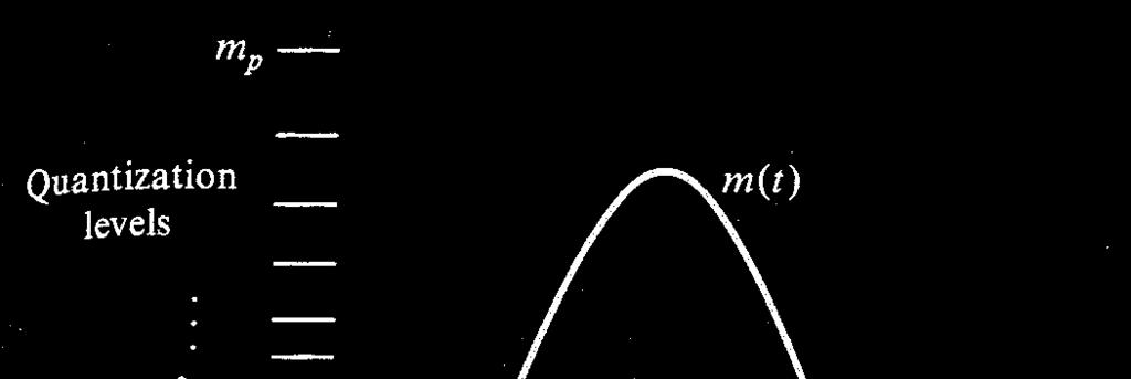
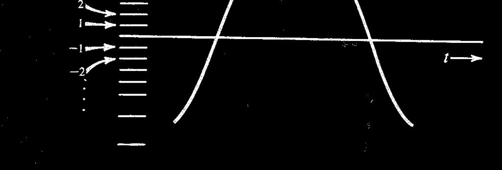
12 Quantization (1) It is the process of transforming the sample amplitude m(nt S ) of a baseband signal at time t = nt S into a discrete amplitude v(nt S ) taken from a finite set of possible levels 12
13 Quantization (2) Quantizer characteristic: k th interval: Here, k = 1, 2, 3,, L L = Number of representation levels (Number of intervals) m k : Decision levels / Decision thresholds v k : Representation levels / Reconstruction levels / Quantization Levels Δ= v k +1 v k = m k +1 m k : Step-size / quantum Quantizer output equals to v k if the input signal sample m belongs to the interval I k (rounding) v v if m I (Rounding) k I k v v k if v k m v k 1 (Truncation) 13
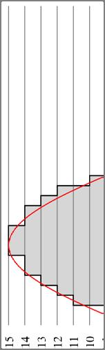
14 Quantization(3): Two types Mid tread quantization Mid rise quantization Representation/ Reconstruction/ Quantization levels Mid tread quantizer: Mid rise quantizer: Reconstruction value is exactly zero Decision threshold value is exactly zero Signal Range (Dynamic range) and Quantizer Range: Could be same or different 14
15 Quantization(4): Example For the following sequence {1.2, -0.2, -0.5, 0.4, 0.89,1.3} quantize it using a uniform quantizer of rounding type and write the quantized sequence. Quantizer range is (-1.5,1.5) with 4 levels. Solution: Yellow dots indicate the decision thresholds (boundaries between separate quantization intervals). Red dots indicate the reconstruction levels (middle of each interval). Thus, 1.2 fall between 0.75 and 1.5, and hence is quantized to Quantized sequence: {1.125, , , 0.375, 1.125, 1.125} 15

16 Quantization(5): Two types Uniform quantization Non uniform quantization 16
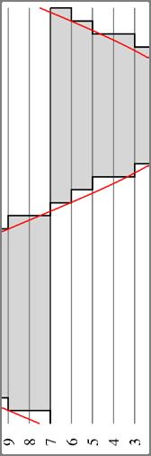
17 Quantization Error for Uniform Quantization (1) Quantization error (noise) q = m v => Q = M V Q is a RV variable of zero mean in the range [ Δ/2, Δ/2] If Δ is sufficiently small, Q can be assumed a uniform RV with zero mean Quantization noise power f Q (q) 1/Δ 2 Q / q f Q qdq 12 / 2 Δ/2 0 Δ/2 q Signal-to-nose-ratio (SNR): SNR P 2 Q 12P P 2 P = Average power of m(t) 17
18 Quantization Error for Uniform Quantization (2) Suppose m(t) of continuous amplitude in the range [ m max, m max ]: 2mmax 2mmax R L 2 R = Number of bits for presenting each level (bits/sample) SNR 3P 2 m 2 max 2R SNR db 3P 6.02R 10log m 2 max Each additional bit increases the SNR by 6.02 db and a corresponding increase in required channel BW Special case: m(t) is a sinusoidal signal with amplitude equal to m max SNR R 6R 1. 8 SNR db 18
19 Non-Uniform Quantization SNR of weak signals is much lower than that of strong signal Instantaneous SNR is also lower for the smaller amplitudes compared to that of the larger amplitudes 19
20 Non-Uniform Quantization Step size increases as the separation from the origin of the input output amplitude characteristic is increased First Compression and then uniform quantization Achieve more even SNR over the dynamic range using fewer bits (e.g., 8 bits instead of 13/14 bits) Receiver side: Expansion required Compression + Expansion = Companding Tx Rx Original Signal Compression Uniform Quantization Reconstruction Expansion Original Signal 20


21 What is Compression? The compression here occurs in the amplitude values Compression in amplitudes means that the amplitudes of the compressed signal are more closely spaced in comparison to the original signal To do so, the compressor boosts the small amplitudes by a large amount. However, the large amplitude values receive very small gain and the maximum value remains the same Compressor Input Compressor Output 21

")


22 Non-Uniform Quantization μ Law: Used in North America, Japan (μ = 255 is mostly used) Compression characteristics (first quadrant shown) More uniform SNR is achieved over a larger dynamic range 22
23 Non-Uniform Quantization A Law: Used in Europe and many other countries A = 87.6 is mostly used and comparable to μ =
24 Encoding Each quantized samples is encoded into a code word Each element in a code word is called code element Binary code: Each code element is either of two distinct values, customarily denoted as 0 and 1 Binary symbol withstands a relatively high level of noise and also easy to regenerate Each binary code word consists of R bits and hence, this code can represent 2 R distinct numbers (i.e., at best R bit quantizer can be used) 24
25 Pulse Code Modulation (PCM) In PCM, a message signal is represented by a sequence of coded pulses, which is accomplished by representing the signal in discrete form in both time and amplitude Transmitter Three basic operations in a PCM Transmitter: Sampling Quantization Encoding Transmission Path Receiver 25
 When a signal is sampled at a rate slightly higher than the Nyquist rate, there exists a high degree correlation between adjacent samples, i.e., in an average sense, the signal does")
26 Differential PCM (DPCM) When a signal is sampled at a rate slightly higher than the Nyquist rate, there exists a high degree correlation between adjacent samples, i.e., in an average sense, the signal does not change rapidly from one sample to the next When these highly correlated samples are encoded as in a standard PCM system, the resulting encoded signal contains redundant information implying that symbols that are not absolutely essential to the transmission of information are generated DPCM removes this redundancy before encoding by taking the difference between the actual sample m(nt S ) and its predicted value mˆ nt S The quantized version of the prediction error e(nt S ) are encoded instead of encoding the samples of the original signal This will result in much smaller quantization intervals leading to less quantization noise and much higher SNR Transmitter e Prediction error nt mnt mˆ nt S S S 26
27 Predictor for DPCM: Liner predictor of order p: Transversal filter (tapped-delay-line filter) used as a linear predictor p nt w m n k mˆ nt S k 1 k q T S Past p samples 27


28 Differential PCM (DPCM) Transmitter e q nt S m ' nt S mˆ nt ' Receiver S m nt ˆ nt nt S m S eq S Reconstruction error ' m nt m nt ent e nt qnt S = Quantization error S S q S S 28
29 Delta Modulation (DM) (1) DM encodes the difference between the current sample and the previous sample using just one bit Correlation between samples are increased by oversampling (i.e., at a rate much higher, typically 4 times higher than the Nyquist rate) DM involves the generation of the staircase approximation of the oversampled version of message The difference between the input and the approximation is quantized into only two levels: 1 bit version of DPCM (i.e., 2 level quantization) requiring less bandwidth than that of DPCM and PCM 29
 (2) Transmitter")

30 Delta Modulation (DM) (2) Transmitter Receiver Digital equivalent of integration 30


31 Predictor for DPCM and DM DM DPCM Note: (1) DPCM uses a higher order filter. (2) DM uses a 1 st order (p=1) predictor with w 1 = 1. Thus, the predicted output is the previous sample. 31
 Granular noise m q (t) e q (nt S ) Comments:")
 has")

32 Delta Modulation (DM) (3) Two types of quantization error: (1) Slope overload distortion/noise (2) Granular noise m q (t) e q (nt S ) Comments: (1) For avoiding slope overload distortion: larger Δ is desired (2) For avoiding granular noise: smaller Δ is desired An optimal step size (Δ) has to be chosen for minimum overall noise Example: Avoiding slope overload mt A t m t max m Am f cos s A m m m T A m f s f s max Voice r r T s max m 32
 methods: Or")
33 Line Coding (1) PCM, DPCM and DM are different strategies for source encoding, which converts an analog signal into digital form Once a binary sequence of 1s and 0s is produced, the sequence is transformed into electrical pulses or waveforms for transmission over a channel and this is known as line coding Multi-level line coding is possible Or NRZ-L Various line coding (binary) methods: Or RZ-AMI (0 means transition) (f) Split-phase or Manchester 33
34 Line Coding (2) Polar NRZ / Book: Digital Communications: Fundamentals and Applications - Bernard Sklar Bipolar NRZ Applications: Polar NRZ / NRZ-L: Digital logic circuits NRZ-M/NRZ-S: Magnetic tap recording RZ line codes: Base band transmission and magnetic recording (e.g., Bipolar RZ / RZ-AMI is used for telephone system) Manchester Coding: Magnetic recording, optical communications and satellite telemetry 34
35 Line Coding (3) 35
36 Line Coding (4) Desired properties (i.e., design criteria) for line coding: Transmission bandwidth: should be as small as possible Noise immunity: should be immune to noise Power efficiency: for a given bandwidth and given error probability, transmission power requirement should be as small as possible Error detection and correction capability: should be possible to detect and correct errors Favorable power spectral density (PSD): should have zero PSD at zero (i.e., DC) frequency, otherwise the ac coupling and the transformers used in communication systems would block the DC component Adequate timing information / self-clocking: should carry the timing or clock information which can be used for self-synchronization Transparency: should be possible to transmit a digital signal correctly regardless of the patterns of 1 s and 0 s (by preventing long string of 0s and 1s) 36
EEE 309 Communication Theory
 EEE 309 Communication Theory Semester: January 2016 Dr. Md. Farhad Hossain Associate Professor Department of EEE, BUET Email: mfarhadhossain@eee.buet.ac.bd Office: ECE 331, ECE Building Part 05 Pulse Code
Digital Communication (650533) CH 3 Pulse Modulation
 CH 3 Pulse Modulation") Philadelphia University/Faculty of Engineering Communication and Electronics Engineering Digital Communication (650533) CH 3 Pulse Modulation Instructor: Eng. Nada Khatib Website: http://www.philadelphia.edu.jo/academics/nkhatib/
Philadelphia University/Faculty of Engineering Communication and Electronics Engineering Digital Communication (650533) CH 3 Pulse Modulation Instructor: Eng. Nada Khatib Website: http://www.philadelphia.edu.jo/academics/nkhatib/
CHAPTER 3 Syllabus (2006 scheme syllabus) Differential pulse code modulation DPCM transmitter
 Differential pulse code modulation DPCM transmitter") CHAPTER 3 Syllabus 1) DPCM 2) DM 3) Base band shaping for data tranmission 4) Discrete PAM signals 5) Power spectra of discrete PAM signal. 6) Applications (2006 scheme syllabus) Differential pulse code
CHAPTER 3 Syllabus 1) DPCM 2) DM 3) Base band shaping for data tranmission 4) Discrete PAM signals 5) Power spectra of discrete PAM signal. 6) Applications (2006 scheme syllabus) Differential pulse code
Communications I (ELCN 306)
") Communications I (ELCN 306) c Samy S. Soliman Electronics and Electrical Communications Engineering Department Cairo University, Egypt Email: samy.soliman@cu.edu.eg Website: http://scholar.cu.edu.eg/samysoliman
Communications I (ELCN 306) c Samy S. Soliman Electronics and Electrical Communications Engineering Department Cairo University, Egypt Email: samy.soliman@cu.edu.eg Website: http://scholar.cu.edu.eg/samysoliman
UNIT TEST I Digital Communication
 Time: 1 Hour Class: T.E. I & II Max. Marks: 30 Q.1) (a) A compact disc (CD) records audio signals digitally by using PCM. Assume the audio signal B.W. to be 15 khz. (I) Find Nyquist rate. (II) If the Nyquist
PULSE CODE MODULATION (PCM)
") PULSE CODE MODULATION (PCM) 1. PCM quantization Techniques 2. PCM Transmission Bandwidth 3. PCM Coding Techniques 4. PCM Integrated Circuits 5. Advantages of PCM 6. Delta Modulation 7. Adaptive Delta Modulation
PULSE CODE MODULATION (PCM) 1. PCM quantization Techniques 2. PCM Transmission Bandwidth 3. PCM Coding Techniques 4. PCM Integrated Circuits 5. Advantages of PCM 6. Delta Modulation 7. Adaptive Delta Modulation
DIGITAL COMMUNICATION
 DEPARTMENT OF ELECTRICAL &ELECTRONICS ENGINEERING DIGITAL COMMUNICATION Spring 00 Yrd. Doç. Dr. Burak Kelleci OUTLINE Quantization Pulse-Code Modulation THE QUANTIZATION PROCESS A continuous signal has
Time division multiplexing The block diagram for TDM is illustrated as shown in the figure
 CHAPTER 2 Syllabus: 1) Pulse amplitude modulation 2) TDM 3) Wave form coding techniques 4) PCM 5) Quantization noise and SNR 6) Robust quantization Pulse amplitude modulation In pulse amplitude modulation,
Comm 502: Communication Theory. Lecture 4. Line Coding M-ary PCM-Delta Modulation
 Comm 502: Communication Theory Lecture 4 Line Coding M-ary PCM-Delta Modulation PCM Decoder PCM Waveform Types (Line Coding) Representation of binary sequence into the electrical signals that enter the
QUESTION BANK. SUBJECT CODE / Name: EC2301 DIGITAL COMMUNICATION UNIT 2
 QUESTION BANK DEPARTMENT: ECE SEMESTER: V SUBJECT CODE / Name: EC2301 DIGITAL COMMUNICATION UNIT 2 BASEBAND FORMATTING TECHNIQUES 1. Why prefilterring done before sampling [AUC NOV/DEC 2010] The signal
Communications and Signals Processing
 Communications and Signals Processing Dr. Ahmed Masri Department of Communications An Najah National University 2012/2013 1 Dr. Ahmed Masri Chapter 5 - Outlines 5.4 Completing the Transition from Analog
EXPERIMENT WISE VIVA QUESTIONS
 EXPERIMENT WISE VIVA QUESTIONS Pulse Code Modulation: 1. Draw the block diagram of basic digital communication system. How it is different from analog communication system. 2. What are the advantages of
Pulse Code Modulation
 Pulse Code Modulation Modulation is the process of varying one or more parameters of a carrier signal in accordance with the instantaneous values of the message signal. The message signal is the signal
Downloaded from 1
 VII SEMESTER FINAL EXAMINATION-2004 Attempt ALL questions. Q. [1] How does Digital communication System differ from Analog systems? Draw functional block diagram of DCS and explain the significance of
Department of Electronics and Communication Engineering 1
 UNIT I SAMPLING AND QUANTIZATION Pulse Modulation 1. Explain in detail the generation of PWM and PPM signals (16) (M/J 2011) 2. Explain in detail the concept of PWM and PAM (16) (N/D 2012) 3. What is the
7.1 Introduction 7.2 Why Digitize Analog Sources? 7.3 The Sampling Process 7.4 Pulse-Amplitude Modulation Time-Division i i Modulation 7.
 Chapter 7 Digital Representation of Analog Signals Wireless Information Transmission System Lab. Institute of Communications Engineering g National Sun Yat-sen University Contents 7.1 Introduction 7.2
Fundamentals of Digital Communication
 Fundamentals of Digital Communication Network Infrastructures A.A. 2017/18 Digital communication system Analog Digital Input Signal Analog/ Digital Low Pass Filter Sampler Quantizer Source Encoder Channel
Class 4 ((Communication and Computer Networks))
)") Class 4 ((Communication and Computer Networks)) Lesson 5... SIGNAL ENCODING TECHNIQUES Abstract Both analog and digital information can be encoded as either analog or digital signals. The particular encoding
Class 4 ((Communication and Computer Networks)) Lesson 5... SIGNAL ENCODING TECHNIQUES Abstract Both analog and digital information can be encoded as either analog or digital signals. The particular encoding
CHAPTER 4. PULSE MODULATION Part 2
 CHAPTER 4 PULSE MODULATION Part 2 Pulse Modulation Analog pulse modulation: Sampling, i.e., information is transmitted only at discrete time instants. e.g. PAM, PPM and PDM Digital pulse modulation: Sampling
Pulse Code Modulation
 Pulse Code Modulation EE 44 Spring Semester Lecture 9 Analog signal Pulse Amplitude Modulation Pulse Width Modulation Pulse Position Modulation Pulse Code Modulation (3-bit coding) 1 Advantages of Digital
Waveform Encoding - PCM. BY: Dr.AHMED ALKHAYYAT. Chapter Two
 Chapter Two Layout: 1. Introduction. 2. Pulse Code Modulation (PCM). 3. Differential Pulse Code Modulation (DPCM). 4. Delta modulation. 5. Adaptive delta modulation. 6. Sigma Delta Modulation (SDM). 7.
Chapter 3 Pulse Modulation
 Chapter 3 Pulse Modulation Outline Sampling Process: Sampling Theory, Anti-Aliasing Pulse Modulation Analog Pulse Modulation: PAM, PDM, PWM, PPM Digital Pulse Modulation: PCM, DM, DPCM Quantization Process:
QUESTION BANK EC 1351 DIGITAL COMMUNICATION YEAR / SEM : III / VI UNIT I- PULSE MODULATION PART-A (2 Marks) 1. What is the purpose of sample and hold
 1. What is the purpose of sample and hold") QUESTION BANK EC 1351 DIGITAL COMMUNICATION YEAR / SEM : III / VI UNIT I- PULSE MODULATION PART-A (2 Marks) 1. What is the purpose of sample and hold circuit 2. What is the difference between natural sampling
QUESTION BANK EC 1351 DIGITAL COMMUNICATION YEAR / SEM : III / VI UNIT I- PULSE MODULATION PART-A (2 Marks) 1. What is the purpose of sample and hold circuit 2. What is the difference between natural sampling
 UNIT III -- DATA AND PULSE COMMUNICATION PART-A 1. State the sampling theorem for band-limited signals of finite energy. If a finite energy signal g(t) contains no frequency higher than W Hz, it is completely
Chapter-3 Waveform Coding Techniques
 Chapter-3 Waveform Coding Techniques PCM [Pulse Code Modulation] PCM is an important method of analog to-digital conversion. In this modulation the analog signal is converted into an electrical waveform
EC 6501 DIGITAL COMMUNICATION UNIT - II PART A
 EC 6501 DIGITAL COMMUNICATION 1.What is the need of prediction filtering? UNIT - II PART A [N/D-16] Prediction filtering is used mostly in audio signal processing and speech processing for representing
Voice Transmission --Basic Concepts--
 Voice Transmission --Basic Concepts-- Voice---is analog in character and moves in the form of waves. 3-important wave-characteristics: Amplitude Frequency Phase Telephone Handset (has 2-parts) 2 1. Transmitter
EEE482F: Problem Set 1
 EEE482F: Problem Set 1 1. A digital source emits 1.0 and 0.0V levels with a probability of 0.2 each, and +3.0 and +4.0V levels with a probability of 0.3 each. Evaluate the average information of the source.
CODING TECHNIQUES FOR ANALOG SOURCES
 CODING TECHNIQUES FOR ANALOG SOURCES Prof.Pratik Tawde Lecturer, Electronics and Telecommunication Department, Vidyalankar Polytechnic, Wadala (India) ABSTRACT Image Compression is a process of removing
 Sixth Semester B.E. Degree Examination, May/June 2010 Digital Communication Note: Answer any FIVEfull questions, selecting at least TWO questionsfrom each part. PART-A a. With a block diagram, explain
Year : TYEJ Sub: Digital Communication (17535) Assignment No. 1. Introduction of Digital Communication. Question Exam Marks
 Assignment No. 1. Introduction of Digital Communication. Question Exam Marks") Assignment 1 Introduction of Digital Communication Sr. Question Exam Marks 1 Draw the block diagram of the basic digital communication system. State the function of each block in detail. W 2015 6 2 State
Assignment 1 Introduction of Digital Communication Sr. Question Exam Marks 1 Draw the block diagram of the basic digital communication system. State the function of each block in detail. W 2015 6 2 State
SEN366 Computer Networks
 SEN366 Computer Networks Prof. Dr. Hasan Hüseyin BALIK (5 th Week) 5. Signal Encoding Techniques 5.Outline An overview of the basic methods of encoding digital data into a digital signal An overview of
EC 2301 Digital communication Question bank
 EC 2301 Digital communication Question bank UNIT I Digital communication system 2 marks 1.Draw block diagram of digital communication system. Information source and input transducer formatter Source encoder
Communication Systems Lecture-12: Delta Modulation and PTM
 Communication Systems Lecture-12: Delta Modulation and PTM Department of Electrical and Computer Engineering Lebanese American University chadi.abourjeily@lau.edu.lb October 26, 2017 Delta Modulation (1)
Lecture 3 Concepts for the Data Communications and Computer Interconnection
 Lecture 3 Concepts for the Data Communications and Computer Interconnection Aim: overview of existing methods and techniques Terms used: -Data entities conveying meaning (of information) -Signals data
QUESTION BANK SUBJECT: DIGITAL COMMUNICATION (15EC61)
") QUESTION BANK SUBJECT: DIGITAL COMMUNICATION (15EC61) Module 1 1. Explain Digital communication system with a neat block diagram. 2. What are the differences between digital and analog communication systems?
QUESTION BANK SUBJECT: DIGITAL COMMUNICATION (15EC61) Module 1 1. Explain Digital communication system with a neat block diagram. 2. What are the differences between digital and analog communication systems?
ECE 556 BASICS OF DIGITAL SPEECH PROCESSING. Assıst.Prof.Dr. Selma ÖZAYDIN Spring Term-2017 Lecture 2
 ECE 556 BASICS OF DIGITAL SPEECH PROCESSING Assıst.Prof.Dr. Selma ÖZAYDIN Spring Term-2017 Lecture 2 Analog Sound to Digital Sound Characteristics of Sound Amplitude Wavelength (w) Frequency ( ) Timbre
Signal Encoding Techniques
 2 Techniques ITS323: to Data Communications CSS331: Fundamentals of Data Communications Sirindhorn International Institute of Technology Thammasat University Prepared by Steven Gordon on 3 August 2015
Digital Communication - Analog to Digital
 Unit 26. Digital Communication Digital Communication - Analog to Digital The communication that occurs in our day-to-day life is in the form of signals. These signals, such as sound signals, generally,
EC6501 Digital Communication
 EC6501 Digital Communication UNIT -1 DIGITAL COMMUNICATION SYSTEMS Digital Communication system 1) Write the advantages and disadvantages of digital communication. [A/M 11] The advantages of digital communication
Chapter 4 Digital Transmission 4.1
 Chapter 4 Digital Transmission 4.1 Copyright The McGraw-Hill Companies, Inc. Permission required for reproduction or display. 4-1 DIGITAL-TO-DIGITAL CONVERSION In this section, we see how we can represent
Communications IB Paper 6 Handout 3: Digitisation and Digital Signals
 Communications IB Paper 6 Handout 3: Digitisation and Digital Signals Jossy Sayir Signal Processing and Communications Lab Department of Engineering University of Cambridge jossy.sayir@eng.cam.ac.uk Lent
QUESTION BANK (VI SEM ECE) (DIGITAL COMMUNICATION)
 (DIGITAL COMMUNICATION)") QUESTION BANK (VI SEM ECE) (DIGITAL COMMUNICATION) UNIT-I: PCM & Delta modulation system Q.1 Explain the difference between cross talk & intersymbol interference. Q.2 What is Quantization error? How does
QUESTION BANK (VI SEM ECE) (DIGITAL COMMUNICATION) UNIT-I: PCM & Delta modulation system Q.1 Explain the difference between cross talk & intersymbol interference. Q.2 What is Quantization error? How does
10 Speech and Audio Signals
 0 Speech and Audio Signals Introduction Speech and audio signals are normally converted into PCM, which can be stored or transmitted as a PCM code, or compressed to reduce the number of bits used to code
LATHA MATHAVAN ENGINEERING COLLEGE Alagarkovil, Madurai
 UNIT I - SAMPLING & QUANTIZATION PART A 1. What is aliasing? (EC6501 June 2016) 2. What is Companding? Sketch the input-output characteristics of a compressor and an expander. (EC6501 June 2016) 3. An
 DEPARTMENT OF COMPUTER GCE@Bodi_ SCIENCE GCE@Bodi_ AND ENIGNEERING GCE@Bodi_ GCE@Bodi_ GCE@Bodi_ Analog and Digital Communication GCE@Bodi_ DEPARTMENT OF CsE Subject Name: Analog and Digital Communication
AMSEC/ECE
 EC6501 -DIGITAL COMMUNICATION UNIT-I SAMPLING & QUANTIZATION 1. Define Dirac comb or ideal sampling function. What is its Fourier Transform? Dirac comb is nothing but a periodic impulse train in which
EE390 Final Exam Fall Term 2002 Friday, December 13, 2002
 Name Page 1 of 11 EE390 Final Exam Fall Term 2002 Friday, December 13, 2002 Notes 1. This is a 2 hour exam, starting at 9:00 am and ending at 11:00 am. The exam is worth a total of 50 marks, broken down
Digital Communication Prof. Bikash Kumar Dey Department of Electrical Engineering Indian Institute of Technology, Bombay
 Digital Communication Prof. Bikash Kumar Dey Department of Electrical Engineering Indian Institute of Technology, Bombay Lecture - 03 Quantization, PCM and Delta Modulation Hello everyone, today we will
Syllabus. osmania university UNIT - I UNIT - II UNIT - III CHAPTER - 1 : INTRODUCTION TO DIGITAL COMMUNICATION CHAPTER - 3 : INFORMATION THEORY
 i Syllabus osmania university UNIT - I CHAPTER - 1 : INTRODUCTION TO Elements of Digital Communication System, Comparison of Digital and Analog Communication Systems. CHAPTER - 2 : DIGITAL TRANSMISSION
DIGITAL COMMUNICATION
 DIGITAL COMMUNICATION TRAINING LAB Digital communication has emerged to augment or replace the conventional analog systems, which had been used widely a few decades back. Digital communication has demonstrated
28. What is meant by repetition rate of the AM envelope? (ADC,AU-2010) 29. Describe the upper and lower sidebands. (ADC, AU-2010) 30.
 29. Describe the upper and lower sidebands. (ADC, AU-2010) 30.") Institute of Road and Transport Technology, Erode Department of Electronics and Communication Engineering Class/Sem: 2 nd Year Information Technology-3rd Semester Subject: Principles of Communication (IT)
Institute of Road and Transport Technology, Erode Department of Electronics and Communication Engineering Class/Sem: 2 nd Year Information Technology-3rd Semester Subject: Principles of Communication (IT)
Data Encoding g(p (part 2)
") Data Encoding g(p (part 2) CSE 3213 Instructor: U.T. Nguyen 10/11/2007 12:44 PM 1 Analog Data, Digital Signals (5.3) 2 1 Analog Data, Digital Signals Digitization Conversion of analog data into digital
Data Encoding g(p (part 2) CSE 3213 Instructor: U.T. Nguyen 10/11/2007 12:44 PM 1 Analog Data, Digital Signals (5.3) 2 1 Analog Data, Digital Signals Digitization Conversion of analog data into digital
SUMMER 14 EXAMINATION Model Answer
 SUMMER 14 EXAMINATION Model Answer Subject Code: 12188 Important Instructions to examiners: 1) The answers should be examined by key words and not as word-to-word as given in the model answer scheme. 2)
END-OF-YEAR EXAMINATIONS ELEC321 Communication Systems (D2) Tuesday, 22 November 2005, 9:20 a.m. Three hours plus 10 minutes reading time.
 Tuesday, 22 November 2005, 9:20 a.m. Three hours plus 10 minutes reading time.") END-OF-YEAR EXAMINATIONS 2005 Unit: Day and Time: Time Allowed: ELEC321 Communication Systems (D2) Tuesday, 22 November 2005, 9:20 a.m. Three hours plus 10 minutes reading time. Total Number of Questions:
END-OF-YEAR EXAMINATIONS 2005 Unit: Day and Time: Time Allowed: ELEC321 Communication Systems (D2) Tuesday, 22 November 2005, 9:20 a.m. Three hours plus 10 minutes reading time. Total Number of Questions:
Digital signal is denoted by discreet signal, which represents digital data.there are three types of line coding schemes available:
 Digital-to-Digital Conversion This section explains how to convert digital data into digital signals. It can be done in two ways, line coding and block coding. For all communications, line coding is necessary
Data Communications and Networking (Module 2)
") Data Communications and Networking (Module 2) Chapter 5 Signal Encoding Techniques References: Book Chapter 5 Data and Computer Communications, 8th edition, by William Stallings 1 Outline Overview Encoding
Data Communications and Networking (Module 2) Chapter 5 Signal Encoding Techniques References: Book Chapter 5 Data and Computer Communications, 8th edition, by William Stallings 1 Outline Overview Encoding
COMPUTER COMMUNICATION AND NETWORKS ENCODING TECHNIQUES
 COMPUTER COMMUNICATION AND NETWORKS ENCODING TECHNIQUES Encoding Coding is the process of embedding clocks into a given data stream and producing a signal that can be transmitted over a selected medium.
Department of Electronics & Telecommunication Engg. LAB MANUAL. B.Tech V Semester [ ] (Branch: ETE)
![Department of Electronics & Telecommunication Engg. LAB MANUAL. B.Tech V Semester [ ] (Branch: ETE)](/thumbs/86/93078052.jpg "Department of Electronics & Telecommunication Engg. LAB MANUAL. B.Tech V Semester [ ] (Branch: ETE)") Department of Electronics & Telecommunication Engg. LAB MANUAL SUBJECT:-DIGITAL COMMUNICATION SYSTEM [BTEC-501] B.Tech V Semester [2013-14] (Branch: ETE) KCT COLLEGE OF ENGG & TECH., FATEHGARH PUNJAB TECHNICAL
Department of Electronics & Telecommunication Engg. LAB MANUAL SUBJECT:-DIGITAL COMMUNICATION SYSTEM [BTEC-501] B.Tech V Semester [2013-14] (Branch: ETE) KCT COLLEGE OF ENGG & TECH., FATEHGARH PUNJAB TECHNICAL
Digital to Digital Encoding
 MODULATION AND ENCODING Data must be transformed into signals to send them from one place to another Conversion Schemes Digital-to-Digital Analog-to-Digital Digital-to-Analog Analog-to-Analog Digital to
Chapter 5: Modulation Techniques. Abdullah Al-Meshal
 Chapter 5: Modulation Techniques Abdullah Al-Meshal Introduction After encoding the binary data, the data is now ready to be transmitted through the physical channel In order to transmit the data in the
Communication Theory II
 Communication Theory II Lecture 17: Conversion of Analog Waveforms into Coded Pulses Ahmed Elnakib, PhD Assistant Professor, Mansoura University, Egypt April 16 th, 2015 1 opulse Modulation Analog Pulse
6. has units of bits/second. a. Throughput b. Propagation speed c. Propagation time d. (b)or(c)
or(c)") King Saud University College of Computer and Information Sciences Information Technology Department First Semester 1436/1437 IT224: Networks 1 Sheet# 10 (chapter 3-4-5) Multiple-Choice Questions 1. Before
King Saud University College of Computer and Information Sciences Information Technology Department First Semester 1436/1437 IT224: Networks 1 Sheet# 10 (chapter 3-4-5) Multiple-Choice Questions 1. Before
Signal Encoding Techniques
 Signal Encoding Techniques Overview Have already noted previous chapters that both analog and digital information can be encoded as either analog or digital signals: Digital data, digital signals: simplest
ANALOGUE AND DIGITAL COMMUNICATION
 ANALOGUE AND DIGITAL COMMUNICATION Syed M. Zafi S. Shah Umair M. Qureshi Lecture xxx: Analogue to Digital Conversion Topics Pulse Modulation Systems Advantages & Disadvantages Pulse Code Modulation Pulse
YEDITEPE UNIVERSITY ENGINEERING FACULTY COMMUNICATION SYSTEMS LABORATORY EE 354 COMMUNICATION SYSTEMS
 YEDITEPE UNIVERSITY ENGINEERING FACULTY COMMUNICATION SYSTEMS LABORATORY EE 354 COMMUNICATION SYSTEMS EXPERIMENT 3: SAMPLING & TIME DIVISION MULTIPLEX (TDM) Objective: Experimental verification of the
: DIGITAL COMMUNICATION
 SRM UNIVERSITY FACULTY OF ENGINEERING AND TECHNOLOGY DEPARTMENT OF ECE COURSE PLAN Course Code : EC0307 Course Title : DIGITAL COMMUNICATION Semester : V Course Time : JULY NOVEMBER 2012 Location : S.R.M.TECH
SUMMER 15 EXAMINATION. 1) The answers should be examined by key words and not as word-to-word as given in the
 The answers should be examined by key words and not as word-to-word as given in the") SUMMER 15 EXAMINATION Subject Code: 17535 Model Answer Important Instructions to examiners: 1) The answers should be examined by key words and not as word-to-word as given in the model answer scheme. 2)
SUMMER 15 EXAMINATION Subject Code: 17535 Model Answer Important Instructions to examiners: 1) The answers should be examined by key words and not as word-to-word as given in the model answer scheme. 2)
DEPARTMENT OF CSE QUESTION BANK
 DEPARTMENT OF CSE QUESTION BANK SUBJECT CODE: CS6304 SUBJECT NAME: ANALOG AND DIGITAL COMMUNICATION Part-A UNIT-I ANALOG COMMUNICATION 1.Define modulation? Modulation is a process by which some characteristics
Lecture 10. Digital Modulation
 Digital Modulation Lecture 10 On-Off keying (OOK), or amplitude shift keying (ASK) Phase shift keying (PSK), particularly binary PSK (BPSK) Frequency shift keying Typical spectra Modulation/demodulation
ITM 1010 Computer and Communication Technologies
 ITM 1010 Computer and Communication Technologies Lecture #20 Review: Communication Technologies 2003 香港中文大學, 電子工程學系 (Prof. H.K.Tsang) ITM 1010 計算機與通訊技術 1 Review of Communication Technologies! Information
KINGS COLLEGE OF ENGINEERING DEPARTMENT OF ELECTRONICS AND COMMUNICATION ENGINEERING QUESTION BANK. Subject Name: Digital Communication Techniques
 KINGS COLLEGE OF ENGINEERING DEPARTMENT OF ELECTRONICS AND COMMUNICATION ENGINEERING QUESTION BANK Subject Code: EC1351 Year/Sem: III/IV Subject Name: Digital Communication Techniques UNIT I PULSE MODULATION
QUESTION BANK. Staff In-Charge: M.MAHARAJA, AP / ECE
 FATIMA MICHAEL COLLEGE OF ENGINEERING & TECHNOLOGY Senkottai Village, Madurai Sivagangai Main Road, Madurai -625 020 An ISO 9001:2008 Certified Institution QUESTION BANK Sub. Code : EC 2301 Class : III
UNIT I Source Coding Systems
 SIDDHARTH GROUP OF INSTITUTIONS: PUTTUR Siddharth Nagar, Narayanavanam Road 517583 QUESTION BANK (DESCRIPTIVE) Subject with Code: DC (16EC421) Year & Sem: III-B. Tech & II-Sem Course & Branch: B. Tech
Basic Concepts in Data Transmission
 Basic Concepts in Data Transmission EE450: Introduction to Computer Networks Professor A. Zahid A.Zahid-EE450 1 Data and Signals Data is an entity that convey information Analog Continuous values within
Contents Preview and Introduction Waveform Encoding
 Contents 1 Preview and Introduction... 1 1.1 Process of Communication..... 1 1.2 General Definition of Signal..... 3 1.3 Time-Value Definition of Signals Analog and Digital..... 6 1.3.1 Continuous Time
CHAPTER 2. Instructor: Mr. Abhijit Parmar Course: Mobile Computing and Wireless Communication ( )
") CHAPTER 2 Instructor: Mr. Abhijit Parmar Course: Mobile Computing and Wireless Communication (2170710) Syllabus Chapter-2.3 Modulation Techniques Reasons for Choosing Encoding Techniques Digital data,
CHAPTER 2 Instructor: Mr. Abhijit Parmar Course: Mobile Computing and Wireless Communication (2170710) Syllabus Chapter-2.3 Modulation Techniques Reasons for Choosing Encoding Techniques Digital data,
Problem Sheet 1 Probability, random processes, and noise
 Problem Sheet 1 Probability, random processes, and noise 1. If F X (x) is the distribution function of a random variable X and x 1 x 2, show that F X (x 1 ) F X (x 2 ). 2. Use the definition of the cumulative
ITM 1010 Computer and Communication Technologies
 ITM 1010 Computer and Communication Technologies Lecture #14 Part II Introduction to Communication Technologies: Digital Signals: Digital modulation, channel sharing 2003 香港中文大學, 電子工程學系 (Prof. H.K.Tsang)
Digital Modulation Lecture 01. Review of Analogue Modulation Introduction to Digital Modulation Techniques Richard Harris
 Digital Modulation Lecture 01 Review of Analogue Modulation Introduction to Digital Modulation Techniques Richard Harris Objectives You will be able to: Classify the various approaches to Analogue Modulation
Ș.l. dr. ing. Lucian-Florentin Bărbulescu
 Ș.l. dr. ing. Lucian-Florentin Bărbulescu 1 Data: entities that convey meaning within a computer system Signals: are the electric or electromagnetic impulses used to encode and transmit data Characteristics
Objectives. Presentation Outline. Digital Modulation Lecture 01
 Digital Modulation Lecture 01 Review of Analogue Modulation Introduction to Digital Modulation Techniques Richard Harris Objectives You will be able to: Classify the various approaches to Analogue Modulation
Chapter 4 Digital Transmission 4.1
 Chapter 4 Digital Transmission 4.1 Copyright The McGraw-Hill Companies, Inc. Permission required for reproduction or display. 4-2 ANALOG-TO-DIGITAL CONVERSION We have seen in Chapter 3 that a digital signal
Chapter 2: Fundamentals of Data and Signals
 Chapter 2: Fundamentals of Data and Signals TRUE/FALSE 1. The terms data and signal mean the same thing. F PTS: 1 REF: 30 2. By convention, the minimum and maximum values of analog data and signals are
DIGITAL COMMUNICATIONS LAB
 DIGITAL COMMUNICATIONS LAB List of Experiments: 1. PCM Generation and Detection. 2. Differential Pulse Code modulation. 3. Delta modulation. 4. Time Division Multiplexing of 2band Limited Signals. 5. Frequency
3.6 Intersymbol interference. 1 Your site here
 3.6 Intersymbol intererence 1 3.6 Intersymbol intererence what is intersymbol intererence and what cause ISI 1. The absolute bandwidth o rectangular multilevel pulses is ininite. The channels bandwidth
BSc (Hons) Computer Science with Network Security, BEng (Hons) Electronic Engineering. Cohorts: BCNS/17A/FT & BEE/16B/FT
 Computer Science with Network Security, BEng (Hons) Electronic Engineering. Cohorts: BCNS/17A/FT & BEE/16B/FT") BSc (Hons) Computer Science with Network Security, BEng (Hons) Electronic Engineering Cohorts: BCNS/17A/FT & BEE/16B/FT Examinations for 2016-2017 Semester 2 & 2017 Semester 1 Resit Examinations for BEE/12/FT
BSc (Hons) Computer Science with Network Security, BEng (Hons) Electronic Engineering Cohorts: BCNS/17A/FT & BEE/16B/FT Examinations for 2016-2017 Semester 2 & 2017 Semester 1 Resit Examinations for BEE/12/FT
SCHEME OF COURSE WORK. Course Code : 13EC1114 L T P C : ELECTRONICS AND COMMUNICATION ENGINEERING
 SCHEME OF COURSE WORK Course Details: Course Title : DIGITAL COMMUNICATIONS Course Code : 13EC1114 L T P C 4 0 0 3 Program Specialization Semester Prerequisites Courses to which it is a prerequisite :
Department of Electronics & Communication Engineering LAB MANUAL SUBJECT: DIGITAL COMMUNICATION LABORATORY [ECE324] (Branch: ECE)
![Department of Electronics & Communication Engineering LAB MANUAL SUBJECT: DIGITAL COMMUNICATION LABORATORY [ECE324] (Branch: ECE)](/thumbs/96/127341232.jpg "Department of Electronics & Communication Engineering LAB MANUAL SUBJECT: DIGITAL COMMUNICATION LABORATORY [ECE324] (Branch: ECE)") Department of Electronics & Communication Engineering LAB MANUAL SUBJECT: DIGITAL COMMUNICATION LABORATORY [ECE324] B.Tech Year 3 rd, Semester - 5 th (Branch: ECE) Version: 01 st August 2018 The LNM Institute
Department of Electronics & Communication Engineering LAB MANUAL SUBJECT: DIGITAL COMMUNICATION LABORATORY [ECE324] B.Tech Year 3 rd, Semester - 5 th (Branch: ECE) Version: 01 st August 2018 The LNM Institute
DIGITAL COMMINICATIONS
 Code No: R346 R Set No: III B.Tech. I Semester Regular and Supplementary Examinations, December - 23 DIGITAL COMMINICATIONS (Electronics and Communication Engineering) Time: 3 Hours Max Marks: 75 Answer
Fundamentals of Data and Signals
 Fundamentals of Data and Signals Chapter 2 Learning Objectives After reading this chapter, you should be able to: Distinguish between data and signals and cite the advantages of digital data and signals
Communication Systems Lab
 LAB MANUAL Communication Systems Lab (EE-226-F) Prepared by: Varun Sharma (Lab In-charge) Dayal C. Sati (Faculty In-charge) B R C M CET BAHAL DEPARTMENT OF ELECTRONICS & COMMUNICATION ENGINEERING Page
Practical Approach of Producing Delta Modulation and Demodulation
 IOSR Journal of Electronics and Communication Engineering (IOSR-JECE) e-issn: 2278-2834,p- ISSN: 2278-8735.Volume 11, Issue 3, Ver. II (May-Jun.2016), PP 87-94 www.iosrjournals.org Practical Approach of
(Refer Slide Time: 3:11)
") Digital Communication. Professor Surendra Prasad. Department of Electrical Engineering. Indian Institute of Technology, Delhi. Lecture-2. Digital Representation of Analog Signals: Delta Modulation. Professor:
Digital Communication. Professor Surendra Prasad. Department of Electrical Engineering. Indian Institute of Technology, Delhi. Lecture-2. Digital Representation of Analog Signals: Delta Modulation. Professor:
Multiplexing Concepts and Introduction to BISDN. Professor Richard Harris
 Multiplexing Concepts and Introduction to BISDN Professor Richard Harris Objectives Define what is meant by multiplexing and demultiplexing Identify the main types of multiplexing Space Division Time Division
2. By convention, the minimum and maximum values of analog data and signals are presented as voltages.
 Chapter 2: Fundamentals of Data and Signals Data Communications and Computer Networks A Business Users Approach 8th Edition White TEST BANK Full clear download (no formatting errors) at: https://testbankreal.com/download/data-communications-computer-networksbusiness-users-approach-8th-edition-white-test-bank/
CSCD 433 Network Programming Fall Lecture 5 Physical Layer Continued
 CSCD 433 Network Programming Fall 2016 Lecture 5 Physical Layer Continued 1 Topics Definitions Analog Transmission of Digital Data Digital Transmission of Analog Data Multiplexing 2 Different Types of
Principles of Baseband Digital Data Transmission
 Principles of Baseband Digital Data Transmission Prof. Wangrok Oh Dept. of Information Communications Eng. Chungnam National University Prof. Wangrok Oh(CNU) / 3 Overview Baseband Digital Data Transmission
<#)*,$+0"$#)* ?">& B"$"')*+0"$#)* ?">&? F. S. Blair March 24, Analog and Digital Signals
*,$+0$#)* ?>& B$')*+0$#)* ?>&? F. S. Blair March 24, Analog and Digital Signals") S. Blair March 24, 2008 8 1.5. Analog and Digital Signals
S. Blair March 24, 2008 8 1.5. Analog and Digital Signals
Line Coding for Digital Communication
 Line Coding for Digital Communication How do we transmit bits over a wire, RF, fiber? Line codes, many options Power spectrum of line codes, how much bandwidth do they take Clock signal and synchronization