Data Communications and Networking (Module 2)
|
|
|
- Warren Lane
- 5 years ago
- Views:
Transcription
1 Data Communications and Networking (Module 2) Chapter 5 Signal Encoding Techniques References: Book Chapter 5 Data and Computer Communications, 8th edition, by William Stallings 1
2 Outline Overview Encoding and Modulation Digital data, digital signal Digital data, analog signal Analog data, digital signal Analog data, analog signal 2
3 Encoding and Modulation 3
4 Modulation Modulation is the process of encoding source data onto a carrier signal with frequency f c. The frequency of the carrier signal is chosen to be compatible with the transmission medium being used. Modulation techniques involve operation on one or more of the three parameters: amplitude, frequency, and phase According to the input source signal m(t) (either analog or digital), which is called baseband signal (or modulating signal), the carrier signal f c (t) will 4 be modulated into modulated signal s(t).
5 Encoding/modulation Techniques Digital data, digital signal The equipment for encoding digital data into a digital signal is less complex and less expensive than digitalto-analog modulation equipment. Eg.NRZ, Biphase, Multilevel binary Analog data, digital signal Conversion of analog data (e.g., voice, video) to digital form permits the use of modern digital transmission & switching. PCM, PM, DM Digital data, analog signal Optical system and unguided media (wireless system) only propagate analog signals. ASK, FSK, PSK Analog data, analog signal Baseband: easy and cheap, e.g., in voice-grade telephone lines, voice signals are transmitted over telephone lines at their original spectrum Modulation permits frequency division multiplexing, e.g., AM/FM radios,pm 5
6 (I) Digital Data, Digital Signal Digital signal is a sequence of discrete, discontinuous voltage pulses. Each pulse is a signal element. Binary data are transmitted by encoding the bit stream into signal elements. In the simplest case, one bit is represented by one signal element. E.g., 1 is represented by a lower voltage level, and 0 is represented by a higher voltage level 6
7 Terminologies Unipolar If all signal elements are on one side of the time axis- NRZ. Polar One logic state represented by positive voltage, the other by negative voltagenrz-l and I,Biphase Data rate Rate of data transmission measured in bps: bits per second Duration or length of a bit Time taken for transmitter to emit the bit Modulation rate Rate at which the signal level changes How are they related? Measured in baud: signal elements per second Mark and Space Mark: Binary 1 Space: Binary 0 7
8 Interpreting Signals at the Receiver The receiver needs to know The timing of each signal element, i.e., when a signal element begins and ends signal levels These tasks are performed by sampling each element position in the middle of the interval and comparing the value to a threshold. Factors affecting successful interpreting of signals Signal-to-noise ratio (SNR) Data rate Bandwidth Some principles: An increase in data rate increases bit error rate (BER) An increase in SNR decreases BER An increase in bandwidth allows an increase in data rate Another factor that can improve performance: Encoding scheme: the mapping from data bits to signal 8 elements
9 Evaluation of Encoding Schemes (1) Signal Spectrum Lack of high frequencies reduces required bandwidth Lack of dc component allows ac coupling via transformer, providing electrical isolation and reducing interference Concentrate power in the middle of the bandwidth Clocking Need to determine the beginning and end of each bit Synchronizing transmitter and receiver 1. Use external clock, which is expensive; or 2. Synchronization mechanism based on the transmitted signal 9
10 Comparison of Encoding Schemes (2) Error detection Various error-detection techniques will be covered in Chapter 9 Some error detection capability can be built into signal encoding scheme Signal interference and noise immunity Some codes are better than others in the presence of noise Performance is usually expressed in terms of BER Cost and complexity Higher signal rate (thus data rate) leads to higher cost Some codes require a signal rate greater than the actual data rate 10
11 Encoding Schemes Nonreturn to Zero (NRZ)(Unipolar) Nonreturn to Zero-Level (NRZ-L) Nonreturn to Zero Inverted (NRZI) Multilevel Binary Bipolar-AMI Pseudoternary Biphase Manchester Differential Manchester Scrambling techniques B8ZS HDB3 polar 11
12 12
13 1. NRZ Unipolar NRZ Polar NRZ:
14 a. Nonreturn to Zero-Level (NRZ-L) Two different voltages for 0 and 1 bits Voltage is constant during a bit interval no transition, i.e. no return to zero voltage E.g. absence of voltage for zero, constant positive voltage for one More often, negative voltage for one value and positive for the other This is known as NRZ-L 14
15 b. Nonreturn to Zero Inverted NRZI: Nonreturn to zero, invert on ones Constant voltage pulse for duration of bit Data are encoded as presence or absence of signal transition at the beginning of the bit time A transition (low to high or high to low) denotes a binary 1 No transition denotes binary 0 NRZI is an example of differential encoding technique 15
16 Differential Encoding Data are represented in terms of the changes between successive signal elements, rather than the signal elements themselves. It is more reliable to detect a transition in the presence of noise than to compare a value to a threshold. With a complex transmission layouts, it is easy to lose the sense of the polarity of the signal. 16
17 NRZ pros and cons Pros Easy to engineer Make efficient use of bandwidth Cons The presence of dc component The lack of synchronization capability NRZ codes are commonly used for digital magnetic recording, but not often used for signal transmission. 17
18 2. a. Multilevel Binary Use more than two levels Bipolar-AMI: alternate mark inversion zero represented by no line signal one represented by a positive or negative pulse one pulses must alternate in polarity Advantages: No loss of synchronization if a long string of 1s occurs (0s still be a problem) No net dc component Provides a simple means of error detection 18
19 b. Pseudoternary 1 represented by the absence of line signal 0 represented by alternating positive and negative pulses No advantage or disadvantage over bipolar-ami 19
20 Bipolar-AMI and Pseudoternary
21 Trade-off for Multilevel Binary Not as efficient as NRZ In a 3 level system, each signal element could represent log 2 3 = 1.58 bits However, in bipolar-ami & pseudoternary, each signal element only represents one bit Receiver must distinguish between three levels (+A, -A, 0) Requires approx. 3dB more signal power for same probability of bit error, or The BER for NRZ codes, at a given SNR, is significantly less than for mulitlevel binary. 21
22 3.Biphase Manchester There is a transition at the middle of each bit period. The midbit transition serves as a clock mechanism and also as data: low to high represents 1, high to low represents 0 Used by IEEE Ethernet LAN Differential Manchester The midbit transition is used only to provide clocking. 0 is represented by the presence of a transition at the beginning of a bit period. 1 is represented by the absence of a transition at the beginning of a bit period. Note: this is a differential encoding scheme Used by IEEE token ring LAN 22
23 Manchester Encoding 23
24 Differential Manchester Encoding 24
25 Biphase Pros and Cons Pros Self-clocking: Because there is a predictable transition during each bit time, the receiver can synchronize on that transition. No dc component Error detection: the absence of an expected transition can be used to detect errors Con Requires at least one transition per bit time and may have as many as two transitions, thus, The maximum modulation rate is twice that for NRZ Requires more bandwidth 25
26 Modulation(Signal/Pulse/Baud) Rate:S 26
27 Data (Bit) Rate: N Duration for 1 bit = 1 microsec Thus N= 1 Mbps r = No of bits per signal element Signal rate S= N/r (Top fig: 1 bit for1 signal element, r=1) S=N/r=1/1=1baud (Lower Fig: 1 bit for 2 signal elment, r=1/2) S=N/r=1/(1/2)=2 baud ie. S=2N 27
28 Bit rate is the number of bits per second. Baud rate is the number of signal elements per second. r=bits per signal element An analog signal carries 4 bits per signal element. If 1000 signal elements are sent per second, find the bit rate. Solution In this case, r = 4, S = 1000, and N is unknown. We can find the value of N from 28
29 An analog signal has a bit rate of 8000 bps and a baud rate of 1000 baud. How many data elements are carried by each signal element? How many signal elements do we need? Solution In this example, S = 1000, N = 8000, and r and L are unknown. We find first the value of r and then the value of L. 29
30 Line coding Unipolar If all signal elements are on one side of the time axis- NRZ. (Avg BW=N/2) Polar One logic state represented by positive voltage, the other by negative voltage :NRZ-L and I (Avg BW=N/2) Biphase Bipolar AMI and Pseudoternary (Avg BW=N/2) (Biphase- Manchester, Differential Manchester (Avg BW=N) ) 30
31 Scrambling Use scrambling to replace sequences that would produce constant voltage Main idea: Sequences that would result in a constant voltage are replaced by filling sequences that will provide sufficient transitions for the receiver s clock to maintain synchronization. Filling sequences must be recognized by receiver and replaced with original data sequence. Filling sequence is the same length as original sequence. Design goals: No dc component No long sequences of zero-level line signals No reduction in data rate Error detection capability 31
32 B8ZS Bipolar With 8-Zeros Substitution Based on bipolar-ami, whose drawback is a long string of zeros may result in loss of synchronization. If octet of all zeros occurs and the last voltage pulse preceding this octet was positive, encode as If octet of all zeros occurs and the last voltage pulse preceding this octet was negative, encode as Causes two violations of AMI code Unlikely to occur as a result of noise Receiver recognizes the pattern and interprets the octet as consisting of all zeros. 32
33 HDB3 High-Density Bipolar-3 Zeros Based on bipolar-ami String of four zeros is replaced with sequences containing one or two pulses. Polarity of Preceding Pulse Number of Bipolar Pulses since last substitution Odd Even
34 B8ZS and HDB3 34
35 (II) Digital Data, Analog Signal E.g., Public telephone system Designed to transmit analog signals in 300Hz to 3400Hz (limited by the central office, not the twisted pair cable) Use modem for digital data (modulator-demodulator) Modulation involves operation on one or more of the three characteristics of a carrier signal Amplitude shift keying (ASK) Frequency shift keying (FSK) Phase shift keying (PSK) QAM: a combination of ASK and PSK 35
36 Digital-to-analog conversion 36
37 37
38 Modulation Techniques 38
39 Binary Amplitude Shift Keying Values are represented by different amplitudes of the carrier frequency Usually, one amplitude is zero (on-off keying OOK) i.e. presence and absence of carrier is used Inefficient: up to 1200bps on voice grade lines ASK is used to transmit digital data over optical fiber. 39
40 40
41 We have an available bandwidth of 100 khz which spans from 200 to 300 khz. What are the carrier frequency and the bit rate if we modulated our data by using ASK with d = 1? Solution The middle of the bandwidth is located at 250 khz. This means that our carrier frequency can be at f c = 250 khz. We can use the formula for bandwidth to find the bit rate (with d = 1 and r = 1). 41
42 Binary Frequency Shift Keying The most common form of FSK is binary FSK (BFSK) Two binary values represented by two different frequencies (near carrier frequency) BFSK is less susceptible to error than ASK. Up to 1200bps on voice grade lines Also used for high frequency (3 to 30MHz) radio 42
43 Binary frequency shift keying 43
44 Multiple FSK MFSK: More than two frequencies are used Each signalling element represents more than one bit More bandwidth efficient But more prone to error! 44
45 Phase Shift Keying In PSK, the phase of the carrier signal is shifted to represent data. Binary PSK Two phases represent two binary digits Differential PSK Phase shifted relative to previous transmission rather than some constant reference signal 45
46 Differential PSK 46
47 Figure 5.9 Binary phase shift keying Figure 5.10 Implementation of BPSK 47
48 Multilevel PSK More efficient use of bandwidth Each signal element represents more than one bit QPSK: quadrature PSK shifts of /2 (90 o ), i.e. 4 different phases Each signal element represents 2 bits Multilevel PSK Can use 8 or more phase angles, and each phase can have more than one amplitude 9600bps modem use 12 angles, four of which have two amplitudes, in total 16 different signal elements 48
49 For QPSK, 2 bits is carried by one signal element 49
50 Concept of a constellation diagram Show the constellation diagrams for an ASK (OOK), BPSK, and QPSK signals. 50
51 Quadrature Amplitude Modulation QAM is used in the asymmetric digital subscriber line (ADSL) and some wireless standards. Combination of ASK and PSK A logical extension of QPSK Send two different signals simultaneously on the same carrier frequency Use two copies of the carrier, one shifted by 90 Each carrier is ASK modulated Two independent signals over same medium Demodulate and combine for original binary output 51
52 QAM Levels Two level ASK Each of two streams in one of two states Four state system Essentially QPSK Four level ASK Combined stream in one of 16 states 64 and 256 state systems have been implemented Improved data rate for given bandwidth Increased potential error rate 52
53 53

54 Analog-to-analog conversion is the representation of analog information by an analog signal Amplitude Modulation Frequency Modulation Phase Modulation 54
55 Amplitude Modulation A carrier signal is modulated only in amplitude value The modulating signal is the envelope of the carrier The required bandwidth is 2B, where B is the bandwidth of the modulating signal Since on both sides of the carrier freq. f c, the spectrum is identical, we can discard one half, thus requiring a smaller bandwidth for transmission. 55

56 Figure 5.16 Amplitude modulation 56
57 Frequency Modulation The modulating signal changes the freq. f c of the carrier signal The bandwidth for FM is high It is approx. 10x the signal frequency 57

58 Figure 5.18 Frequency modulation 58

59 Figure 5.17 AM band allocation Figure 5.19 FM band allocation 59
60 Phase Modulation (PM) The modulating signal only changes the phase of the carrier signal. The phase change manifests itself as a frequency change but the instantaneous frequency change is proportional to the derivative of the amplitude. The bandwidth is higher than for AM. 60

61 Figure 5.20 Phase modulation 61
62 (III) Analog Data, Digital Signal Digitization Conversion of analog data into digital data Digital data can then be transmitted using NRZ-L Digital data can then be transmitted using code other than NRZ-L Digital data can then be converted to analog signal Analog to digital conversion done using a codec (coder-decoder) Two principle codec techniques Pulse Code Modulation Delta modulation 62
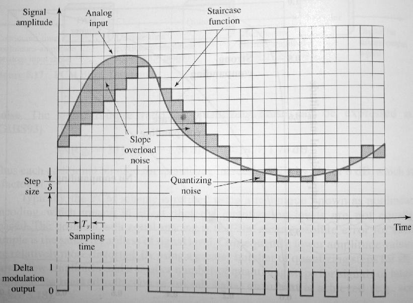
63 Digitizing Analog Data 63
64 Pulse Code Modulation Sampling Theorem: If a signal is sampled at regular intervals of time and at a rate higher than twice the highest signal frequency, then the samples contain all the information of the original signal. For example, voice data are limited to below 4000Hz 8000 samples per second is sufficient to characterize the voice signal. Samples are analog samples, called Pulse Amplitude Modulation (PAM) samples. To convert to digital, each analog sample must be assigned a binary code. 64
65 Pulse Code Modulation Each sample is quantized into some level The original signal is now only approximated and cannot be recovered exactly This effect is called quantizing error or quantizing noise For example, 8 bit sample gives 256 levels 8000 samples per second and 8 bits per sample gives 64kbps, for a single voice signal. 65

66 PCM Example 66

67 PCM Block Diagram 67
68 Nonlinear Encoding Typically, PCM scheme is refined using nonlinear encoding. Quantization levels are not equally spaced. The problem of equal spacing: The mean absolute error for each sample is regardless of signal level. Lower amplitude values are relatively more distorted. Nonlinear encoding: Use a greater number of quantizing steps for signals of low amplitude, and a smaller number of quantizing steps for signals of large amplitude Reduces overall signal distortion 68

69 Effect of Non-Linear Coding 69
70 Delta Modulation Modulation: An analog signal is approximated by a staircase function that moves up or down by quantization level at each sampling interval. If the value of the sampled waveform exceeds that of the staircase function, 1 is generated, otherwise, 0 is generated. Two important parameters: The size of the step. The sampling rate. 70
71 71
72 Delta Modulation Noise Slope overload noise (when the analog waveform is changing rapidly than the staircase can follow) Quantizing noise (when the analog waveform is changing slowly) Trade-off The quantizing noise increases as the size of the step increases. The slope overload noise increases as the size of the step decreases. 72
73 (IV) Analog Data, Analog Signals Modulation: Combine an input signal m(t) and a carrier frequency f c to produce a signal s(t) whose bandwidth is usually centered on f c E.g., voice signals are transmitted over telephone lines at their original spectrum. Types of modulation Amplitude modulation: AM Angle Modulation Frequency modulation: FM Phase modulation: PM 73
74 Analog Modulation 74
75 KEY POINTS Both analog and digital information can be encoded as either analog or digital signals. The particular encoding that is chosen depends on the specific requirements to be met and the media and communications facilities available. Digital data, digital signal: The simplest form of digital encoding of digital data is to assign one voltage level to binary one and another to binary zero. More complex encoding schemes are used to improve performance, by altering the spectrum of the signal and providing synchronization capability. Digital data, analog signal: A modem converts digital data to an analog signal so that it can be transmitted over an analog line. The basic techniques are ASK, FSK, and PSK. 75
76 KEY POINTS Analog data, digital signals: Analog data, such as voice and video, are often digitized to be able to use digital transmission facilities. The simplest technique is PCM (Pulse Code Modulation), which involve sampling the analog data periodically and quantizing the samples. Another technique is Delta Modulation. Analog data, analog signals: Analog data are modulated by a carrier frequency to produce an analog signal in a different frequency band, which can be utilized on an analog transmission system. The basic techniques are AM (Amplitude Modulation), FM (Frequency Modulation), and PM (Phase Modulation). 76
77 Data Communications and Networking (Module 2) Chapter 5 Signal Encoding Techniques References: Book Chapter 5 Data and Computer Communications, 8th edition, by William Stallings 1
78 Basis for comparison Synchronous Transmission Asynchronous Transmission Meaning Sends data in the form of blocks or frames Sends 1 byte or character at a time Transmission Technique Used parallel communication Used serial communication Distance limitation Short distance Long distance Transmission Speed Fast Slow Sync method Clock speed Start and stop bit Cost Expensive Economical Time Interval Constant Random Gap between the data Absent Present Bandwidth loss 5% over capacity 20% to 30% over capacity Examples Chat Rooms, Video Conferencing, Telephonic Conversations, etc Letters, s, forums, etc Figure 2
79 3
80 Outline Overview Encoding and Modulation Digital data, digital signal Digital data, analog signal Analog data, digital signal Analog data, analog signal 4
81 Encoding and Modulation 5
82 Modulation Modulation is the process of encoding source data onto a carrier signal with frequency f c. The frequency of the carrier signal is chosen to be compatible with the transmission medium being used. Modulation techniques involve operation on one or more of the three parameters: amplitude, frequency, and phase According to the input source signal m(t) (either analog or digital), which is called baseband signal (or modulating signal), the carrier signal f c (t) will 6 be modulated into modulated signal s(t).
83 Encoding/modulation Techniques Digital data, digital signal The equipment for encoding digital data into a digital signal is less complex and less expensive than digitalto-analog modulation equipment. Eg.NRZ, Biphase, Multilevel binary Analog data, digital signal Conversion of analog data (e.g., voice, video) to digital form permits the use of modern digital transmission & switching. PCM, PM, DM Digital data, analog signal Optical system and unguided media (wireless system) only propagate analog signals. ASK, FSK, PSK Analog data, analog signal Baseband: easy and cheap, e.g., in voice-grade telephone lines, voice signals are transmitted over telephone lines at their original spectrum Modulation permits frequency division multiplexing, e.g., AM/FM radios,pm 7
84 (I) Digital Data, Digital Signal Digital signal is a sequence of discrete, discontinuous voltage pulses. Each pulse is a signal element. Binary data are transmitted by encoding the bit stream into signal elements. In the simplest case, one bit is represented by one signal element. E.g., 1 is represented by a lower voltage level, and 0 is represented by a higher voltage level 8
85 Terminologies Unipolar If all signal elements are on one side of the time axis- NRZ. Polar One logic state represented by positive voltage, the other by negative voltagenrz-l and I,Biphase Data rate Rate of data transmission measured in bps: bits per second Duration or length of a bit Time taken for transmitter to emit the bit Modulation rate Rate at which the signal level changes How are they related? Measured in baud: signal elements per second Mark and Space Mark: Binary 1 Space: Binary 0 9
86 Interpreting Signals at the Receiver The receiver needs to know The timing of each signal element, i.e., when a signal element begins and ends signal levels These tasks are performed by sampling each element position in the middle of the interval and comparing the value to a threshold. Factors affecting successful interpreting of signals Signal-to-noise ratio (SNR) Data rate Bandwidth Some principles: An increase in data rate increases bit error rate (BER) An increase in SNR decreases BER An increase in bandwidth allows an increase in data rate Another factor that can improve performance: Encoding scheme: the mapping from data bits to signal 10 elements
87 Evaluation of Encoding Schemes (1) Signal Spectrum Lack of high frequencies reduces required bandwidth Lack of dc component allows ac coupling via transformer, providing electrical isolation and reducing interference Concentrate power in the middle of the bandwidth Clocking Need to determine the beginning and end of each bit Synchronizing transmitter and receiver 1. Use external clock, which is expensive; or 2. Synchronization mechanism based on the transmitted signal 11
88 Comparison of Encoding Schemes (2) Error detection Various error-detection techniques will be covered in Chapter 9 Some error detection capability can be built into signal encoding scheme Signal interference and noise immunity Some codes are better than others in the presence of noise Performance is usually expressed in terms of BER Cost and complexity Higher signal rate (thus data rate) leads to higher cost Some codes require a signal rate greater than the actual data rate 12
89 Encoding Schemes Nonreturn to Zero (NRZ)(Unipolar) Nonreturn to Zero-Level (NRZ-L) Nonreturn to Zero Inverted (NRZI) Multilevel Binary Bipolar-AMI Pseudoternary Biphase Manchester Differential Manchester Scrambling techniques B8ZS HDB3 polar 13
90 14
91 1. NRZ Unipolar NRZ Polar NRZ:
92 a. Nonreturn to Zero-Level (NRZ-L) Two different voltages for 0 and 1 bits Voltage is constant during a bit interval no transition, i.e. no return to zero voltage E.g. absence of voltage for zero, constant positive voltage for one More often, negative voltage for one value and positive for the other This is known as NRZ-L 16
93 b. Nonreturn to Zero Inverted NRZI: Nonreturn to zero, invert on ones Constant voltage pulse for duration of bit Data are encoded as presence or absence of signal transition at the beginning of the bit time A transition (low to high or high to low) denotes a binary 1 No transition denotes binary 0 NRZI is an example of differential encoding technique 17
94 Differential Encoding Data are represented in terms of the changes between successive signal elements, rather than the signal elements themselves. It is more reliable to detect a transition in the presence of noise than to compare a value to a threshold. With a complex transmission layouts, it is easy to lose the sense of the polarity of the signal. 18
95 NRZ pros and cons Pros Easy to engineer Make efficient use of bandwidth Cons The presence of dc component The lack of synchronization capability NRZ codes are commonly used for digital magnetic recording, but not often used for signal transmission. 19
96 2. a. Multilevel Binary Use more than two levels Bipolar-AMI: alternate mark inversion zero represented by no line signal one represented by a positive or negative pulse one pulses must alternate in polarity Advantages: No loss of synchronization if a long string of 1s occurs (0s still be a problem) No net dc component Provides a simple means of error detection 20
97 b. Pseudoternary 1 represented by the absence of line signal 0 represented by alternating positive and negative pulses No advantage or disadvantage over bipolar-ami 21
98 Bipolar-AMI and Pseudoternary
99 Trade-off for Multilevel Binary Not as efficient as NRZ In a 3 level system, each signal element could represent log 2 3 = 1.58 bits However, in bipolar-ami & pseudoternary, each signal element only represents one bit Receiver must distinguish between three levels (+A, -A, 0) Requires approx. 3dB more signal power for same probability of bit error, or The BER for NRZ codes, at a given SNR, is significantly less than for mulitlevel binary. 23
100 3.Biphase Manchester There is a transition at the middle of each bit period. The midbit transition serves as a clock mechanism and also as data: low to high represents 1, high to low represents 0 Used by IEEE Ethernet LAN Differential Manchester The midbit transition is used only to provide clocking. 0 is represented by the presence of a transition at the beginning of a bit period. 1 is represented by the absence of a transition at the beginning of a bit period. Note: this is a differential encoding scheme Used by IEEE token ring LAN 24
101 Manchester Encoding 25
102 Differential Manchester Encoding 26
103 Biphase Pros and Cons Pros Self-clocking: Because there is a predictable transition during each bit time, the receiver can synchronize on that transition. No dc component Error detection: the absence of an expected transition can be used to detect errors Con Requires at least one transition per bit time and may have as many as two transitions, thus, The maximum modulation rate is twice that for NRZ Requires more bandwidth 27
104 Modulation(Signal/Pulse/Baud) Rate:S 28
105 Data (Bit) Rate: N Duration for 1 bit = 1 microsec Thus N= 1 Mbps r = No of bits per signal element Signal rate S= N/r (Top fig: 1 bit for1 signal element, r=1) S=N/r=1/1=1baud (Lower Fig: 1 bit for 2 signal elment, r=1/2) S=N/r=1/(1/2)=2 baud ie. S=2N 29
106 Bit rate is the number of bits per second. Baud rate is the number of signal elements per second. r=bits per signal element An analog signal carries 4 bits per signal element. If 1000 signal elements are sent per second, find the bit rate. Solution In this case, r = 4, S = 1000, and N is unknown. We can find the value of N from 30
107 An analog signal has a bit rate of 8000 bps and a baud rate of 1000 baud. How many data elements are carried by each signal element? How many signal elements do we need? Solution In this example, S = 1000, N = 8000, and r and L are unknown. We find first the value of r and then the value of L. 31
108 Line coding Unipolar If all signal elements are on one side of the time axis- NRZ. (Avg BW=N/2) Polar One logic state represented by positive voltage, the other by negative voltage :NRZ-L and I (Avg BW=N/2) Biphase Bipolar AMI and Pseudoternary (Avg BW=N/2) (Biphase- Manchester, Differential Manchester (Avg BW=N) ) 32
109 Scrambling Use scrambling to replace sequences that would produce constant voltage Main idea: Sequences that would result in a constant voltage are replaced by filling sequences that will provide sufficient transitions for the receiver s clock to maintain synchronization. Filling sequences must be recognized by receiver and replaced with original data sequence. Filling sequence is the same length as original sequence. Design goals: No dc component No long sequences of zero-level line signals No reduction in data rate Error detection capability 33
110 (II) Digital Data, Analog Signal E.g., Public telephone system Designed to transmit analog signals in 300Hz to 3400Hz (limited by the central office, not the twisted pair cable) Use modem for digital data (modulator-demodulator) Modulation involves operation on one or more of the three characteristics of a carrier signal Amplitude shift keying (ASK) Frequency shift keying (FSK) Phase shift keying (PSK) QAM: a combination of ASK and PSK 34
111 Digital-to-analog conversion 35
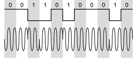
112 36
113 Modulation Techniques 37
114 Binary Amplitude Shift Keying Values are represented by different amplitudes of the carrier frequency Usually, one amplitude is zero (on-off keying OOK) i.e. presence and absence of carrier is used Inefficient: up to 1200bps on voice grade lines ASK is used to transmit digital data over optical fiber. 38
115 39
116 We have an available bandwidth of 100 khz which spans from 200 to 300 khz. What are the carrier frequency and the bit rate if we modulated our data by using ASK with d = 1? Solution The middle of the bandwidth is located at 250 khz. This means that our carrier frequency can be at f c = 250 khz. We can use the formula for bandwidth to find the bit rate (with d = 1 and r = 1). 40
117 Frequency Shift Keying The most common form of FSK is binary FSK (BFSK) Two binary values represented by two different frequencies (near carrier frequency) BFSK is less susceptible to error than ASK. Up to 1200bps on voice grade lines Also used for high frequency (3 to 30MHz) radio 41
118 Binary frequency shift keying 42
119 Phase Shift Keying Phase of the carrier is varied to represent digital data (binary 0 or 1) Amplitude and frequency remains constant. If phase 0 deg to represent 0, 180 deg to represent 1. (2-PSK) PSK is not susceptible to noise degradation that affects ASK or bandwidth limitations of FSK
120 Figure 5.9 Binary phase shift keying (Making 1- in phase and 0 out of phase) Figure 5.10 Implementation of BPSK 44
121 Multilevel PSK More efficient use of bandwidth Each signal element represents more than one bit QPSK: quadrature PSK shifts of /2 (90 o ), i.e. 4 different phases Each signal element represents 2 bits 45
122 4-PSK (QPSK) method 46
123 8-PSK We can extend, by varying the the signal by shifts of 45 deg (instead of 90 deg in 4-PSK) With 8 = 2 3 different phases, each phase can represents 3 bits (tribit). 47
124 For QPSK, 2 bits is carried by one signal element (Optional- Implementation) 48
125 Concept of a constellation diagram Show the constellation diagrams for an ASK (OOK), BPSK, and QPSK signals. 49
126 Calculate the baud rate for the given bit rate and type of modulation. i) 2000 bps, BFSK ii) 4000 bps, BASK iii) 6000 bps, QPSK (Dec 2016) i) r=log 2 L L from the name BFSK-> L=2 r=log 2 2 S=N/r N=2000bps Thus S= 2000/1=2000 baud Similarly ii) 4000 baud iii) 3000 baud 50
127 Quadrature Amplitude Modulation QAM is used in the asymmetric digital subscriber line (ADSL) and some wireless standards. Combination of ASK and PSK A logical extension of QPSK Send two different signals simultaneously on the same carrier frequency Use two copies of the carrier, one shifted by 90 Each carrier is ASK modulated Two independent signals over same medium Demodulate and combine for original binary output 51
128 8-QAM and 16-QAM 8 QAM 16 QAM Constellation diagram 52
129 Modulation of Digital Data 1. Digital-to-Analog Conversion 2. Amplitude Shift Keying (ASK) 3. Frequency Shift Keying (FSK) 4. Phase Shift Keying (PSK) 5. Quadrature Amplitude Modulation (QAM) 6. Bit/Baud Comparison 7. Modems
130 Digital-to-analog modulation Types of digital-to-analog modulation
131 Aspects to digital-to Analog conversion Bit Rate / Baud Rate Bit rate is the number of bits per second. Baud rate is the number of signal units per second. Baud rate is less than or equal to the bit rate. Bit rate is important in computer efficiency Baud rate is important in data transmission. Baud rate determines the bandwidth required to send signal Baud rate = bit rate / # bits per signal unit An analog signal carries 4 bits in each signal unit. If 1000 signal units are sent per second, find the baud rate and the bit rate Baud rate = 1000 bauds per second (baud/s) Bit rate = 1000 x 4 = 4000 bps The bit rate of a signal is If each signal unit carries 6 bits, what is the baud rate? Baud rate = 3000/6 =500 bauds/sec
132 Amplitude Shift Keying (ASK) Acos(2 f ct) binary1 s( t) 0 binary0 On/Off keying The strength of the carrier signal is varied to represent binary 1 and 0. Frequency and phase remains the same. Highly susceptible to noise interference. Used up to 1200 bps on voice grade lines, and on optical fiber.
133 Relationship between baud rate and bandwidth in ASK BW = (1 + d) * N d Find the minimum bandwidth for an ASK signal transmitting at 2000 bps. The transmission mode is half-duplex. In ASK the baud rate and bit rate are the same. The baud rate is therefore An ASK signal requires a minimum bandwidth equal to its baud rate. Therefore, the minimum bandwidth is 2000 Hz.

134 Full duplex ASK Given a bandwidth of 10,000 Hz (1000 to 11,000 Hz), if draw the full-duplex ASK diagram of the system. We can find the carriers and the bandwidths in each direction. Assume there is no gap between the bands in the two directions. For full-duplex ASK, the bandwidth for each direction is BW = / 2 = 5000 Hz The carrier frequencies can be chosen at the middle of each band fc (forward) = /2 = 3500 Hz fc (backward) = /2 = 8500 Hz
135 Frequency Shift Keying Frequency of the carrier is varied to represent digital data (binary 0/1) Peak amplitude and phase remain constant. Avoid noise interference by looking at frequencies (change of a signal) and ignoring amplitudes. Limitations of FSK is the physical capabilities of the carrier. f 1 and f 2 equally offset by equal opposite amounts to the carrier freq. In MFSK more than 2 freq are used, each signal element represents more than one bit Acos(2 f1t) s( t) Acos(2 f 2t) binary1 binary0

136 Relationship between baud rate and bandwidth in FSK FSK shifts between two carrier frequencies FSK spectrum = combination of two ASK spectra centered on f c1 and f c0. BW = f c1 -f c0 + N baud
137 FSK Examples (cont.) What is the Find the minimum bandwidth for an FSK signal transmitting at 2000 bps. Transmission is in half-duplex mode, and the carriers are separated by 3000 Hz. Because For FSK BW = baud rate + f c1 - f c0 BW = bit rate + fc1 - fc0 = = 5000 Hz What is the maximum bit rates for an FSK signal if the bandwidth of the medium is 12,000 Hz and the difference between the two carriers is 2000 Hz. Transmission is in fullduplex mode. Because the transmission is full duplex, only 6000 Hz is allocated for each direction. BW = baud rate + fc 1 - fc 0 Baud rate = BW - (fc 1 - fc 0 ) = = 4000 But because the baud rate is the same as the bit rate, the bit rate is 4000 bps.
138 Phase Shift Keying Phase of the carrier is varied to represent digital data (binary 0 or 1) Amplitude and frequency remains constant. If phase 0 deg to represent 0, 180 deg to represent 1. (2-PSK) PSK is not susceptible to noise degradation that affects ASK or bandwidth limitations of FSK
139 4-PSK (QPSK) method
140 8-PSK We can extend, by varying the the signal by shifts of 45 deg (instead of 90 deg in 4-PSK) With 8 = 2 3 different phases, each phase can represents 3 bits (tribit).

141 Relationship between baud rate and bandwidth in PSK Bandwith similar to ASK, but data rate can 2 or more times greater. What is the bandwidth for a 4-PSK signal transmitting at 2000 bps. Transmission is in half-duplex mode. For PSK the baud rate is the same as the bandwidth, which means the baud rate is But in 8-PSK the bit rate is 3 times the baud rate, so the bit rate is 15,000 bps. Given a bandwidth of 5000 Hz for an 8-PSK signal, what are the baud rate and bit rate? For PSK the baud rate is the same as the bandwidth, which means the baud rate is But in 8-PSK the bit rate is 3 times the baud rate, so the bit rate is 15,000 bps.
 is achieved.")
142 Quadrature Amplitude Modulation PSK is limited by the ability of the equipment to distinguish between small differences in phases. Limits the potential data rate. Quadrature amplitude modulation is a combination of ASK and PSK so that a maximum contrast between each signal unit (bit, dibit, tribit, and so on) is achieved. We can have x variations in phase and y variations of amplitude x y possible variation (greater data rates) Numerous variations. (4-QAM, 8-QAM) # of phase shifts > # of amplitude shifts
143 8-QAM and 16-QAM 8 QAM Second example, recommendation of OSI. not all possibilities are used, to increase readability of signal, measurable differences between shifts are increased First example handles noise best Because of ratio of phases to amplitudes ITU-T recommendation. 16 QAM Constellation diagram
 Assuming 8-QAM, baud rate is only 400 to achieve")

144 Bit Baud comparison Assuming a FSK signal over voice-grade phone line can send 1200 bps, it requires 1200 signal units to send 1200 bits (each frequency shift represents one bit, baud rate 1200) Assuming 8-QAM, baud rate is only 400 to achieve same data rate. Modulation Units Bits/Ba ud Baud rate Bit Rate ASK, FSK, 2-PSK Bit 1 N N 4-PSK, 4-QAM Dibit 2 N 2N 8-PSK, 8-QAM Tribit 3 N 3N 16-QAM Quadbit 4 N 4N 32-QAM Pentabit 5 N 5N 64-QAM Hexabit 6 N 6N 128-QAM Septabit 7 N 7N 256-QAM Octabit 8 N 8N
145 Bit Baud comparison (examples) A constellation diagram consists of eight equally spaced points on a circle. If the bit rate is 4800 bps, what is the baud rate? The constellation indicates 8-PSK with the points 45 degrees apart. Since 2 3 = 8, 3 bits are transmitted with each signal unit. Therefore, the baud rate is 4800 / 3 = 1600 baud What is the bit rate for a 1000-baud 16-QAM signal. A 16-QAM signal has 4 bits per signal unit since log 2 16 = 4. Thus, (1000)(4) = 4000 bps Compute the baud rate for a 72,000-bps 64-QAM signal. A 64-QAM signal has 6 bits per signal unit since log 2 64 = 6. Therefore, / 6 = 12,000 baud

146 Phone modems
147 V-series (ITU-T Standards) V-32. Uses a combined modulation and encoding technique: Trellis coded Modulation. Trellis = QAM + a redundant bit 5 bit (pentabit) = 4 data + 1 calculated from data. A signal distorted by noise can arrive closer to an adjacent point than the intended point (extra bit is therefore used to adjust) Less likely to be misread than a QAM signal baud 4 bit = 9600 bps
148 V-series (cont.) V-32.bis First ITU-T standard to support 14,400 bps transmission. Uses 128-QAM (7 bits/baud with 1 bit for error control) at a rate 2400 baud 2400 * 6 = 14,400 bps Adjustment of the speed upward or downward depending on the quality of the line or signal V-34 bis Bit rate of 28,800 bps with 960-point constellation to 1664-point constellation for a bit rate of 33,600 bps.
 V-90 modems can be used (up to 56Kbps) if using digital signaling.")
 has a 56 Kbps limitation. Uploading rate (from PC to IST) has a 33.")
149 V-series (cont.) V-90 Traditionally modems have a limitation on data rate (max Kbps) V-90 modems can be used (up to 56Kbps) if using digital signaling. For example, Through an Internet Service Provider (ISP) V-90 are asymmetric Downloading rate (from ISP to PC) has a 56 Kbps limitation. Uploading rate (from PC to IST) has a 33.6 Kbps limitation.
150 V-90/92 (cont.) V-90 In uploading, signal still to be sampled at the switching station. Limit due to noise sampling. Phone company samples at 8000 times/sec with 8 bits (including bit error) Data rate = 8000 * 7 = 56Kbps In download, signal is not affected by sampling. V-92 Speed adjustment Upload data at 48Kbps. Call waiting service

151 Analog-to-analog modulation Why analog to analog conversion?

152 Amplitude modulation The total bandwidth required for AM can be determined from the bandwidth of the audio signal: BWt = 2 x BWm.

153 AM band allocation Bandwidth of an audio signal is 5KHz. An AM radio station needs at least a minimum bandwidth of 10 KHz. AM stations are allowed carrier freq between 530 and 1700 KHz. If One station uses 1100 KHz the next one uses 1110 KHz


154 Frequency modulation The bandwidth of a stereo audio signal is usually 15 KHz. Therefore, an FM station needs at least a bandwidth of 150 KHz. The minimum bandwidth is at least 200 KHz (0.2 MHz).
155 FM band allocation
SEN366 Computer Networks
 SEN366 Computer Networks Prof. Dr. Hasan Hüseyin BALIK (5 th Week) 5. Signal Encoding Techniques 5.Outline An overview of the basic methods of encoding digital data into a digital signal An overview of
Digital to Digital Encoding
 MODULATION AND ENCODING Data must be transformed into signals to send them from one place to another Conversion Schemes Digital-to-Digital Analog-to-Digital Digital-to-Analog Analog-to-Analog Digital to
Signal Encoding Techniques
 Signal Encoding Techniques Overview Have already noted previous chapters that both analog and digital information can be encoded as either analog or digital signals: Digital data, digital signals: simplest
Chapter 5 Analog Transmission
 5-1 DIGITAL-TO-ANALOG CONVERSION Chapter 5 Analog Transmission Digital-to-analog conversion is the process of changing one of the characteristics of an analog signal depending on the information in digital
Signal Encoding Techniques
 2 Techniques ITS323: to Data Communications CSS331: Fundamentals of Data Communications Sirindhorn International Institute of Technology Thammasat University Prepared by Steven Gordon on 3 August 2015
CHAPTER 2. Instructor: Mr. Abhijit Parmar Course: Mobile Computing and Wireless Communication ( )
") CHAPTER 2 Instructor: Mr. Abhijit Parmar Course: Mobile Computing and Wireless Communication (2170710) Syllabus Chapter-2.3 Modulation Techniques Reasons for Choosing Encoding Techniques Digital data,
CHAPTER 2 Instructor: Mr. Abhijit Parmar Course: Mobile Computing and Wireless Communication (2170710) Syllabus Chapter-2.3 Modulation Techniques Reasons for Choosing Encoding Techniques Digital data,
Class 4 ((Communication and Computer Networks))
)") Class 4 ((Communication and Computer Networks)) Lesson 5... SIGNAL ENCODING TECHNIQUES Abstract Both analog and digital information can be encoded as either analog or digital signals. The particular encoding
Class 4 ((Communication and Computer Networks)) Lesson 5... SIGNAL ENCODING TECHNIQUES Abstract Both analog and digital information can be encoded as either analog or digital signals. The particular encoding
Overview. Chapter 4. Design Factors. Electromagnetic Spectrum
 Chapter 4 Transmission Media Overview Guided - wire Unguided - wireless Characteristics and quality determined by medium and signal For guided, the medium is more important For unguided, the bandwidth
Lecture 3 Concepts for the Data Communications and Computer Interconnection
 Lecture 3 Concepts for the Data Communications and Computer Interconnection Aim: overview of existing methods and techniques Terms used: -Data entities conveying meaning (of information) -Signals data
COMPUTER COMMUNICATION AND NETWORKS ENCODING TECHNIQUES
 COMPUTER COMMUNICATION AND NETWORKS ENCODING TECHNIQUES Encoding Coding is the process of embedding clocks into a given data stream and producing a signal that can be transmitted over a selected medium.
Chapter 4 Digital Transmission 4.1
 Chapter 4 Digital Transmission 4.1 Copyright The McGraw-Hill Companies, Inc. Permission required for reproduction or display. 4-1 DIGITAL-TO-DIGITAL CONVERSION In this section, we see how we can represent
Data Encoding g(p (part 2)
") Data Encoding g(p (part 2) CSE 3213 Instructor: U.T. Nguyen 10/11/2007 12:44 PM 1 Analog Data, Digital Signals (5.3) 2 1 Analog Data, Digital Signals Digitization Conversion of analog data into digital
Data Encoding g(p (part 2) CSE 3213 Instructor: U.T. Nguyen 10/11/2007 12:44 PM 1 Analog Data, Digital Signals (5.3) 2 1 Analog Data, Digital Signals Digitization Conversion of analog data into digital
College of information Technology Department of Information Networks Telecommunication & Networking I Chapter 5. Analog Transmission
 Analog Transmission 5.1 DIGITAL-TO-ANALOG CONVERSION Digital-to-analog conversion is the process of changing one of the characteristics of an analog signal based on the information in digital data. The
Data Communication (CS601)
") Data Communication (CS601) MOST LATEST (2012) PAPERS For MID Term (ZUBAIR AKBAR KHAN) Page 1 Q. Suppose a famous Telecomm company AT&T is using AMI encoding standard for its digital telephone services,
Data Communication (CS601) MOST LATEST (2012) PAPERS For MID Term (ZUBAIR AKBAR KHAN) Page 1 Q. Suppose a famous Telecomm company AT&T is using AMI encoding standard for its digital telephone services,
Datacommunication I. Layers of the OSI-model. Lecture 3. signal encoding, error detection/correction
 Datacommunication I Lecture 3 signal encoding, error detection/correction Layers of the OSI-model repetition 1 The OSI-model and its networking devices repetition The OSI-model and its networking devices
C06a: Digital Modulation
 CISC 7332X T6 C06a: Digital Modulation Hui Chen Department of Computer & Information Science CUNY Brooklyn College 10/2/2018 CUNY Brooklyn College 1 Outline Digital modulation Baseband transmission Line
B.E SEMESTER: 4 INFORMATION TECHNOLOGY
 B.E SEMESTER: 4 INFORMATION TECHNOLOGY 1 Prepared by: Prof. Amish Tankariya SUBJECT NAME : DATA COMMUNICATION & NETWORKING 2 Subject Code 141601 1 3 TOPIC: DIGITAL-TO-DIGITAL CONVERSION Chap: 5. ENCODING
9.4. Synchronization:
 9.4. Synchronization: It is the process of timing the serial transmission to properly identify the data being sent. There are two most common modes: Synchronous transmission: Synchronous transmission relies
Lecture-8 Transmission of Signals
 Lecture-8 Transmission of Signals The signals are transmitted as electromagnetic waveforms. As the signal may be analog or digital, there four case of signal transmission. Analog data Analog Signal:- The
COSC 3213: Computer Networks I: Chapter 3 Handout #4. Instructor: Dr. Marvin Mandelbaum Department of Computer Science York University Section A
 COSC 3213: Computer Networks I: Chapter 3 Handout #4 Instructor: Dr. Marvin Mandelbaum Department of Computer Science York University Section A Topics: 1. Line Coding: Unipolar, Polar,and Inverted ; Bipolar;
6. has units of bits/second. a. Throughput b. Propagation speed c. Propagation time d. (b)or(c)
or(c)") King Saud University College of Computer and Information Sciences Information Technology Department First Semester 1436/1437 IT224: Networks 1 Sheet# 10 (chapter 3-4-5) Multiple-Choice Questions 1. Before
King Saud University College of Computer and Information Sciences Information Technology Department First Semester 1436/1437 IT224: Networks 1 Sheet# 10 (chapter 3-4-5) Multiple-Choice Questions 1. Before
Digital Transmission
 Digital Transmission Line Coding Some Characteristics Line Coding Schemes Some Other Schemes Line coding Signal level versus data level DC component Pulse Rate versus Bit Rate Bit Rate = Pulse Rate x Log2
CS601 Data Communication Solved Objective For Midterm Exam Preparation
 CS601 Data Communication Solved Objective For Midterm Exam Preparation Question No: 1 Effective network mean that the network has fast delivery, timeliness and high bandwidth duplex transmission accurate
Chapter 2: Fundamentals of Data and Signals
 Chapter 2: Fundamentals of Data and Signals TRUE/FALSE 1. The terms data and signal mean the same thing. F PTS: 1 REF: 30 2. By convention, the minimum and maximum values of analog data and signals are
UNIT TEST I Digital Communication
 Time: 1 Hour Class: T.E. I & II Max. Marks: 30 Q.1) (a) A compact disc (CD) records audio signals digitally by using PCM. Assume the audio signal B.W. to be 15 khz. (I) Find Nyquist rate. (II) If the Nyquist
Lecture Outline. Data and Signals. Analogue Data on Analogue Signals. OSI Protocol Model
 Lecture Outline Data and Signals COMP312 Richard Nelson richardn@cs.waikato.ac.nz http://www.cs.waikato.ac.nz Analogue Data on Analogue Signals Digital Data on Analogue Signals Analogue Data on Digital
Data Encoding. Two devices are used for producing the signals: CODECs produce DIGITAL signals MODEMs produce ANALOGUE signals
 Data Encoding Data are propagated from point to point by encoding data into signals The data may be analogue or digital Likewise the signals may be analogue or digital Two devices are used for producing
Basic Concepts in Data Transmission
 Basic Concepts in Data Transmission EE450: Introduction to Computer Networks Professor A. Zahid A.Zahid-EE450 1 Data and Signals Data is an entity that convey information Analog Continuous values within
2. By convention, the minimum and maximum values of analog data and signals are presented as voltages.
 Chapter 2: Fundamentals of Data and Signals Data Communications and Computer Networks A Business Users Approach 8th Edition White TEST BANK Full clear download (no formatting errors) at: https://testbankreal.com/download/data-communications-computer-networksbusiness-users-approach-8th-edition-white-test-bank/
Lecture (06) Digital Coding techniques (II) Coverting Digital data to Digital Signals
 Digital Coding techniques (II) Coverting Digital data to Digital Signals") Lecture (06) Digital Coding techniques (II) Coverting Digital data to Digital Signals Agenda Objective Line Coding Block Coding Scrambling Dr. Ahmed ElShafee ١ Dr. Ahmed ElShafee, ACU Spring 2016, Data
Lecture (06) Digital Coding techniques (II) Coverting Digital data to Digital Signals Agenda Objective Line Coding Block Coding Scrambling Dr. Ahmed ElShafee ١ Dr. Ahmed ElShafee, ACU Spring 2016, Data
CS601-Data Communication Latest Solved Mcqs from Midterm Papers
 CS601-Data Communication Latest Solved Mcqs from Midterm Papers May 07,2011 Lectures 1-22 Moaaz Siddiq Latest Mcqs MIDTERM EXAMINATION Spring 2010 Question No: 1 ( Marks: 1 ) - Please choose one Effective
Hello and welcome to today s lecture. In the last couple of lectures we have discussed about various transmission media.
 Data Communication Prof. Ajit Pal Department of Computer Science & Engineering Indian Institute of Technology, Kharagpur Lecture No # 7 Transmission of Digital Signal-I Hello and welcome to today s lecture.
Chapter Two. Fundamentals of Data and Signals. Data Communications and Computer Networks: A Business User's Approach Seventh Edition
 Chapter Two Fundamentals of Data and Signals Data Communications and Computer Networks: A Business User's Approach Seventh Edition After reading this chapter, you should be able to: Distinguish between
Department of Electronics & Telecommunication Engg. LAB MANUAL. B.Tech V Semester [ ] (Branch: ETE)
![Department of Electronics & Telecommunication Engg. LAB MANUAL. B.Tech V Semester [ ] (Branch: ETE)](/thumbs/86/93078052.jpg "Department of Electronics & Telecommunication Engg. LAB MANUAL. B.Tech V Semester [ ] (Branch: ETE)") Department of Electronics & Telecommunication Engg. LAB MANUAL SUBJECT:-DIGITAL COMMUNICATION SYSTEM [BTEC-501] B.Tech V Semester [2013-14] (Branch: ETE) KCT COLLEGE OF ENGG & TECH., FATEHGARH PUNJAB TECHNICAL
Department of Electronics & Telecommunication Engg. LAB MANUAL SUBJECT:-DIGITAL COMMUNICATION SYSTEM [BTEC-501] B.Tech V Semester [2013-14] (Branch: ETE) KCT COLLEGE OF ENGG & TECH., FATEHGARH PUNJAB TECHNICAL
CHAPTER 3 Syllabus (2006 scheme syllabus) Differential pulse code modulation DPCM transmitter
 Differential pulse code modulation DPCM transmitter") CHAPTER 3 Syllabus 1) DPCM 2) DM 3) Base band shaping for data tranmission 4) Discrete PAM signals 5) Power spectra of discrete PAM signal. 6) Applications (2006 scheme syllabus) Differential pulse code
CHAPTER 3 Syllabus 1) DPCM 2) DM 3) Base band shaping for data tranmission 4) Discrete PAM signals 5) Power spectra of discrete PAM signal. 6) Applications (2006 scheme syllabus) Differential pulse code
5.1 DIGITAL-TO-ANALOG CONVERSION
 CHAPTERS Analog Transmission n Chapter 3, we discussed the advantages and disadvantages of digital and analog transmission. We saw that while digital transmission is very desirable, a low-pass channel
Lecture (07) Digital Modulation Digital data transmission through analog signals
 Digital Modulation Digital data transmission through analog signals") Lecture (07) Digital Modulation Digital data transmission through analog signals Dr. Ahmed ElShafee Agenda Aspects of Digital Modulation Amplitude Shift Keying Frequency Shift Keying Phase Shift Keying
Lecture (07) Digital Modulation Digital data transmission through analog signals Dr. Ahmed ElShafee Agenda Aspects of Digital Modulation Amplitude Shift Keying Frequency Shift Keying Phase Shift Keying
EEE 309 Communication Theory
 EEE 309 Communication Theory Semester: January 2017 Dr. Md. Farhad Hossain Associate Professor Department of EEE, BUET Email: mfarhadhossain@eee.buet.ac.bd Office: ECE 331, ECE Building Types of Modulation
Introduction to Communications Part Two: Physical Layer Ch5: Analog Transmission. Goals of This Class. Warm Up. Outline of the Class
 Introduction to Communications Part Two: Physical Layer Ch5: Analog Transmission Kuang Chiu Huang TCM NCKU Spring/2008 2009/4/11 KuangChiu Huang 1 Goals of This Class Through the lecture of analog transmission,
Objectives. Presentation Outline. Digital Modulation Lecture 01
 Digital Modulation Lecture 01 Review of Analogue Modulation Introduction to Digital Modulation Techniques Richard Harris Objectives You will be able to: Classify the various approaches to Analogue Modulation
Digital Modulation Lecture 01. Review of Analogue Modulation Introduction to Digital Modulation Techniques Richard Harris
 Digital Modulation Lecture 01 Review of Analogue Modulation Introduction to Digital Modulation Techniques Richard Harris Objectives You will be able to: Classify the various approaches to Analogue Modulation
Fundamentals of Data and Signals
 Fundamentals of Data and Signals Chapter 2 Learning Objectives After reading this chapter, you should be able to: Distinguish between data and signals and cite the advantages of digital data and signals
Wireless Communications
 2. Physical Layer DIN/CTC/UEM 2018 Periodic Signal Periodic signal: repeats itself in time, that is g(t) = g(t + T ) in which T (given in seconds [s]) is the period of the signal g(t) The number of cycles
CHETTINAD COLLEGE OF ENGINEERING & TECHNOLOGY NH-67, TRICHY MAIN ROAD, PULIYUR, C.F , KARUR DT.
 CHETTINAD COLLEGE OF ENGINEERING & TECHNOLOGY NH-67, TRICHY MAIN ROAD, PULIYUR, C.F. 639 114, KARUR DT. DEPARTMENT OF ELECTRONICS AND COMMUNICATION ENGINEERING COURSE MATERIAL Subject Name: Analog & Digital
DIGITAL COMMUNICATION
 DIGITAL COMMUNICATION TRAINING LAB Digital communication has emerged to augment or replace the conventional analog systems, which had been used widely a few decades back. Digital communication has demonstrated
Digital Transmission
 Digital Transmission 4.1 DIGITAL-TO-DIGITAL CONVERSION In this section, we see how we can represent digital data by using digital signals. The conversion involves three techniques: line coding, block coding,
NETWORKS FOR EMBEDDED SYSTEMS. (Data Communications and Applications to Automotive)
") NETWORKS FOR EMBEDDED SYSTEMS (Data Communications and Applications to Automotive) Important Note! Slides are mostly based on selected references and intended as an interactive support during lectures
NETWORKS FOR EMBEDDED SYSTEMS (Data Communications and Applications to Automotive) Important Note! Slides are mostly based on selected references and intended as an interactive support during lectures
Analog Transmission CHAPTER
 CHAPTER 5 Analog Transmission n Chapter 3, we discussed the advantages and disadvantages of digital and analog transmission. We saw that while digital transmission is very desirable, a low-pass channel
CS441 Mobile & Wireless Computing Communication Basics
 Department of Computer Science Southern Illinois University Carbondale CS441 Mobile & Wireless Computing Communication Basics Dr. Kemal Akkaya E-mail: kemal@cs.siu.edu Kemal Akkaya Mobile & Wireless Computing
Chapter 5: Modulation Techniques. Abdullah Al-Meshal
 Chapter 5: Modulation Techniques Abdullah Al-Meshal Introduction After encoding the binary data, the data is now ready to be transmitted through the physical channel In order to transmit the data in the
Comm 502: Communication Theory. Lecture 4. Line Coding M-ary PCM-Delta Modulation
 Comm 502: Communication Theory Lecture 4 Line Coding M-ary PCM-Delta Modulation PCM Decoder PCM Waveform Types (Line Coding) Representation of binary sequence into the electrical signals that enter the
Downloaded from 1
 VII SEMESTER FINAL EXAMINATION-2004 Attempt ALL questions. Q. [1] How does Digital communication System differ from Analog systems? Draw functional block diagram of DCS and explain the significance of
QUESTION BANK SUBJECT: DIGITAL COMMUNICATION (15EC61)
") QUESTION BANK SUBJECT: DIGITAL COMMUNICATION (15EC61) Module 1 1. Explain Digital communication system with a neat block diagram. 2. What are the differences between digital and analog communication systems?
QUESTION BANK SUBJECT: DIGITAL COMMUNICATION (15EC61) Module 1 1. Explain Digital communication system with a neat block diagram. 2. What are the differences between digital and analog communication systems?
Digital Transmission (Line Coding) EE4367 Telecom. Switching & Transmission. Pulse Transmission
 EE4367 Telecom. Switching & Transmission. Pulse Transmission") Digital Transmission (Line Coding) Pulse Transmission Source Multiplexer Line Coder Line Coding: Output of the multiplexer (TDM) is coded into electrical pulses or waveforms for the purpose of transmission
Digital Transmission (Line Coding) Pulse Transmission Source Multiplexer Line Coder Line Coding: Output of the multiplexer (TDM) is coded into electrical pulses or waveforms for the purpose of transmission
Year : TYEJ Sub: Digital Communication (17535) Assignment No. 1. Introduction of Digital Communication. Question Exam Marks
 Assignment No. 1. Introduction of Digital Communication. Question Exam Marks") Assignment 1 Introduction of Digital Communication Sr. Question Exam Marks 1 Draw the block diagram of the basic digital communication system. State the function of each block in detail. W 2015 6 2 State
Assignment 1 Introduction of Digital Communication Sr. Question Exam Marks 1 Draw the block diagram of the basic digital communication system. State the function of each block in detail. W 2015 6 2 State
Analog Transmission 5.1 DIGITAL-TO-ANALOG CONVERSION
 Analog Transmission In Chapter 3, we discussed the advantages and disadvantages of digital and analog transmission. We saw that while digital transmission is very desirable, a low-pass channel is needed.
Qiz 1. 3.discrete time signals can be obtained by a continuous-time signal. a. sampling b. digitizing c.defined d.
 Qiz 1 Q1: 1.A periodic signal has a bandwidth of 20 Hz the highest frequency is 60Hz. what is the lowest frequency. a.20 b.40 c.60 d.30 2. find the value of bandwidth of the following signal S(t)=(1/5)
CSE 123: Computer Networks Alex C. Snoeren. Project 1 out Today, due 10/26!
 CSE 123: Computer Networks Alex C. Snoeren Project 1 out Today, due 10/26! Signaling Types of physical media Shannon s Law and Nyquist Limit Encoding schemes Clock recovery Manchester, NRZ, NRZI, etc.
Ș.l. dr. ing. Lucian-Florentin Bărbulescu
 Ș.l. dr. ing. Lucian-Florentin Bărbulescu 1 Data: entities that convey meaning within a computer system Signals: are the electric or electromagnetic impulses used to encode and transmit data Characteristics
Wireless Communication Fading Modulation
 EC744 Wireless Communication Fall 2008 Mohamed Essam Khedr Department of Electronics and Communications Wireless Communication Fading Modulation Syllabus Tentatively Week 1 Week 2 Week 3 Week 4 Week 5
CHAPTER 2 DIGITAL MODULATION
 2.1 INTRODUCTION CHAPTER 2 DIGITAL MODULATION Referring to Equation (2.1), if the information signal is digital and the amplitude (lv of the carrier is varied proportional to the information signal, a
CSE 461 Bits and Links. David Wetherall
 CSE 461 Bits and Links David Wetherall djw@cs.washington.edu Topic How do we send a message across a wire or wireless link? The physical/link layers: 1. Different kinds of media 2. Fundamental limits 3.
CSCD 433 Network Programming Fall Lecture 5 Physical Layer Continued
 CSCD 433 Network Programming Fall 2016 Lecture 5 Physical Layer Continued 1 Topics Definitions Analog Transmission of Digital Data Digital Transmission of Analog Data Multiplexing 2 Different Types of
 DEPARTMENT OF COMPUTER GCE@Bodi_ SCIENCE GCE@Bodi_ AND ENIGNEERING GCE@Bodi_ GCE@Bodi_ GCE@Bodi_ Analog and Digital Communication GCE@Bodi_ DEPARTMENT OF CsE Subject Name: Analog and Digital Communication
Introduction: Presence or absence of inherent error detection properties.
 Introduction: Binary data can be transmitted using a number of different types of pulses. The choice of a particular pair of pulses to represent the symbols 1 and 0 is called Line Coding and the choice
DIGITAL COMMUNICATIONS SYSTEMS. MSc in Electronic Technologies and Communications
 DIGITAL COMMUNICATIONS SYSTEMS MSc in Electronic Technologies and Communications Bandpass binary signalling The common techniques of bandpass binary signalling are: - On-off keying (OOK), also known as
Chapter 12: Digital Modulation and Modems
 Chapter 12: Digital Modulation and Modems MULTIPLE CHOICE 1. FSK stands for: a. Full-Shift Keying c. Full-Signal Keying b. Frequency-Shift Keying d. none of the above 2. PSK stands for: a. Pulse-Signal
Department of Electronics and Communication Engineering 1
 UNIT I SAMPLING AND QUANTIZATION Pulse Modulation 1. Explain in detail the generation of PWM and PPM signals (16) (M/J 2011) 2. Explain in detail the concept of PWM and PAM (16) (N/D 2012) 3. What is the
ECE5713 : Advanced Digital Communications
 ECE5713 : Advanced Digital Communications Bandpass Modulation MPSK MASK, OOK MFSK 04-May-15 Advanced Digital Communications, Spring-2015, Week-8 1 In-phase and Quadrature (I&Q) Representation Any bandpass
EEE 309 Communication Theory
 EEE 309 Communication Theory Semester: January 2016 Dr. Md. Farhad Hossain Associate Professor Department of EEE, BUET Email: mfarhadhossain@eee.buet.ac.bd Office: ECE 331, ECE Building Part 05 Pulse Code
CSCD 433 Network Programming Fall Lecture 5 Physical Layer Continued
 CSCD 433 Network Programming Fall 2016 Lecture 5 Physical Layer Continued 1 Topics Definitions Analog Transmission of Digital Data Digital Transmission of Analog Data Multiplexing 2 Different Types of
CSEP 561 Bits and Links. David Wetherall
 CSEP 561 Bits and Links David Wetherall djw@cs.washington.edu Topic How do we send a message across a wire or wireless link? The physical/link layers: 1. Different kinds of media 2. Fundamental limits
EXPERIMENT WISE VIVA QUESTIONS
 EXPERIMENT WISE VIVA QUESTIONS Pulse Code Modulation: 1. Draw the block diagram of basic digital communication system. How it is different from analog communication system. 2. What are the advantages of
Physical Layer. Networked Systems (H) Lecture 3
 Lecture 3") Physical Layer Networked Systems (H) Lecture 3 This work is licensed under the Creative Commons Attribution-NoDerivatives 4.0 International License. To view a copy of this license, visit http://creativecommons.org/licenses/by-nd/4.0/
Physical Layer Networked Systems (H) Lecture 3 This work is licensed under the Creative Commons Attribution-NoDerivatives 4.0 International License. To view a copy of this license, visit http://creativecommons.org/licenses/by-nd/4.0/
Physical Layer, Part 2. Analog and Digital Transmission
 CS 656 Analog/Digital, Page 1 Physical Layer, Part 2 Analog and Digital Transmission These slides are created by Dr. Yih Huang of George Mason University. Students registered in Dr. Huang s courses at
Chapter 2. Physical Layer
 Chapter 2 Physical Layer Lecture 1 Outline 2.1 Analog and Digital 2.2 Transmission Media 2.3 Digital Modulation and Multiplexing 2.4 Transmission Impairment 2.5 Data-rate Limits 2.6 Performance Physical
Point-to-Point Communications
 Point-to-Point Communications Key Aspects of Communication Voice Mail Tones Alphabet Signals Air Paper Media Language English/Hindi English/Hindi Outline of Point-to-Point Communication 1. Signals basic
Digital Modulation Schemes
 Digital Modulation Schemes 1. In binary data transmission DPSK is preferred to PSK because (a) a coherent carrier is not required to be generated at the receiver (b) for a given energy per bit, the probability
EE3723 : Digital Communications
 EE3723 : Digital Communications Week 8-9: Bandpass Modulation MPSK MASK, OOK MFSK 04-May-15 Muhammad Ali Jinnah University, Islamabad - Digital Communications - EE3723 1 In-phase and Quadrature (I&Q) Representation
Digital Communication (650533) CH 3 Pulse Modulation
 CH 3 Pulse Modulation") Philadelphia University/Faculty of Engineering Communication and Electronics Engineering Digital Communication (650533) CH 3 Pulse Modulation Instructor: Eng. Nada Khatib Website: http://www.philadelphia.edu.jo/academics/nkhatib/
Philadelphia University/Faculty of Engineering Communication and Electronics Engineering Digital Communication (650533) CH 3 Pulse Modulation Instructor: Eng. Nada Khatib Website: http://www.philadelphia.edu.jo/academics/nkhatib/
CTD600 Communication Trainer kit
 kit Digital RELATED PRODUCTS v Analog s v Optical Fibers s v Digital and Analog s v Communication Electronic Trainers v Function Generator and Power Supply v Multiple Signal Generator and 1 Line Code 2
Lecture 3: Modulation & Clock Recovery. CSE 123: Computer Networks Stefan Savage
 Lecture 3: Modulation & Clock Recovery CSE 123: Computer Networks Stefan Savage Lecture 3 Overview Signaling constraints Shannon s Law Nyquist Limit Encoding schemes Clock recovery Manchester, NRZ, NRZI,
This Lecture. BUS Computer Facilities Network Management. Communications Model. Encoding Techniques
 This Lecture US35 - omputer Facilities Network Management igital data, igital signals: NRL, iphase, Multilevel binary. Modulation rate, Scrambling. igital data, nalog signals Encoding techniques. SK, FSK,
ECE 435 Network Engineering Lecture 4
 ECE 435 Network Engineering Lecture 4 Vince Weaver http://web.eece.maine.edu/~vweaver vincent.weaver@maine.edu 12 September 2016 Announcements Homework 2 was posted late, due next Monday Homework 1 grades
Physical Layer. Networks: Physical Layer 1
 Physical Layer Networks: Physical Layer 1 Physical Layer Part 1 Definitions Nyquist Theorem - noiseless Shannon s Result with noise Analog versus Digital Amplifier versus Repeater Networks: Physical Layer
OptiSystem applications: Digital modulation analysis (PSK)
") OptiSystem applications: Digital modulation analysis (PSK) 7 Capella Court Nepean, ON, Canada K2E 7X1 +1 (613) 224-4700 www.optiwave.com 2009 Optiwave Systems, Inc. Introduction PSK modulation Digital
OptiSystem applications: Digital modulation analysis (PSK) 7 Capella Court Nepean, ON, Canada K2E 7X1 +1 (613) 224-4700 www.optiwave.com 2009 Optiwave Systems, Inc. Introduction PSK modulation Digital
Signals and codes. Path and modulation
 Signals and codes Path and modulation Communication system The goal is to transfer a status message from source to destination. Signal quality is decreased by channel noise / interference Transferred message
Communications I (ELCN 306)
") Communications I (ELCN 306) c Samy S. Soliman Electronics and Electrical Communications Engineering Department Cairo University, Egypt Email: samy.soliman@cu.edu.eg Website: http://scholar.cu.edu.eg/samysoliman
Communications I (ELCN 306) c Samy S. Soliman Electronics and Electrical Communications Engineering Department Cairo University, Egypt Email: samy.soliman@cu.edu.eg Website: http://scholar.cu.edu.eg/samysoliman
(Refer Slide Time: 2:23)
") Data Communications Prof. A. Pal Department of Computer Science & Engineering Indian Institute of Technology, Kharagpur Lecture-11B Multiplexing (Contd.) Hello and welcome to today s lecture on multiplexing
Data Communications Prof. A. Pal Department of Computer Science & Engineering Indian Institute of Technology, Kharagpur Lecture-11B Multiplexing (Contd.) Hello and welcome to today s lecture on multiplexing
BSc (Hons) Computer Science with Network Security. Examinations for Semester 1
 Computer Science with Network Security. Examinations for Semester 1") BSc (Hons) Computer Science with Network Security Cohort: BCNS/15B/FT Examinations for 2015-2016 Semester 1 MODULE: DATA COMMUNICATIONS MODULE CODE: CAN1101C Duration: 2 Hours Instructions to Candidates:
BSc (Hons) Computer Science with Network Security Cohort: BCNS/15B/FT Examinations for 2015-2016 Semester 1 MODULE: DATA COMMUNICATIONS MODULE CODE: CAN1101C Duration: 2 Hours Instructions to Candidates:
EITF25 Internet Techniques and Applications L2: Physical layer. Stefan Höst
 EITF25 Internet Techniques and Applications L2: Physical layer Stefan Höst Data vs signal Data: Static representation of information For storage Signal: Dynamic representation of information For transmission
Digital modulation techniques
 Outline Introduction Signal, random variable, random process and spectra Analog modulation Analog to digital conversion Digital transmission through baseband channels Signal space representation Optimal
Lecture 5 Transmission
 Lecture 5 Transmission David Andersen Department of Computer Science Carnegie Mellon University 15-441 Networking, Spring 2005 http://www.cs.cmu.edu/~srini/15-441/s05 1 Physical and Datalink Layers: 3
SUMMER 15 EXAMINATION. 1) The answers should be examined by key words and not as word-to-word as given in the
 The answers should be examined by key words and not as word-to-word as given in the") SUMMER 15 EXAMINATION Subject Code: 17535 Model Answer Important Instructions to examiners: 1) The answers should be examined by key words and not as word-to-word as given in the model answer scheme. 2)
SUMMER 15 EXAMINATION Subject Code: 17535 Model Answer Important Instructions to examiners: 1) The answers should be examined by key words and not as word-to-word as given in the model answer scheme. 2)
Digital signal is denoted by discreet signal, which represents digital data.there are three types of line coding schemes available:
 Digital-to-Digital Conversion This section explains how to convert digital data into digital signals. It can be done in two ways, line coding and block coding. For all communications, line coding is necessary
Basic Communications Theory Chapter 2
 TEMPEST Engineering and Hardware Design Dr. Bruce C. Gabrielson, NCE 1998 Basic Communications Theory Chapter 2 Communicating Information Communications occurs when information is transmitted or sent between
 UNIT III -- DATA AND PULSE COMMUNICATION PART-A 1. State the sampling theorem for band-limited signals of finite energy. If a finite energy signal g(t) contains no frequency higher than W Hz, it is completely
Chapter 6 Bandwidth Utilization: Multiplexing and Spreading 6.1
 Chapter 6 Bandwidth Utilization: Multiplexing and Spreading 6.1 Copyright The McGraw-Hill Companies, Inc. Permission required for reproduction or display. 3-6 PERFORMANCE One important issue in networking
Computer Facilities and Network Management BUS3150 Assignment 1
 Computer Facilities and Network Management BUS3150 Assignment 1 Due date: Friday 1st September 2006 (Week 7) This Assignment has 6 questions, and you should complete answers for all 6. The Assignment contributes
The Physical Layer Outline
 The Physical Layer Outline Theoretical Basis for Data Communications Digital Modulation and Multiplexing Guided Transmission Media (copper and fiber) Public Switched Telephone Network and DSLbased Broadband