Reduction of Mutual Coupling in Closely Spaced Strip Dipole Antennas with Elliptical Metasurfaces. Hossein M. Bernety and Alexander B.
|
|
|
- August Murphy
- 6 years ago
- Views:
Transcription
 University of Mississippi UM NSF-BWAC Planning Grant Workshop")
1 Reduction of Mutual Coupling in Closely Spaced Strip Dipole Antennas with Elliptical Metasurfaces Hossein M. Bernety and Alexander B. Yakovlev Department of Electrical Engineering Center for Applied Electromagnetic Systems Research (CAESR) University of Mississippi UM NSF-BWAC Planning Grant Workshop Oxford, Mississippi January 15-16,
2 Introduction and Motivation Mantle Cloaking Outline Analytical and Full-wave Simulation Results Dielectric Elliptical Cylinders at Microwave and Terahertz Frequencies PEC Elliptical Cylinders at Microwave and Terahertz Frequencies Strip as a Degenerated Ellipse Application Reduction of the Mutual Coupling Between Two Strip Dipole Antennas Conclusions 2


3 Cloaking with a Metasurface Mantle Cloaking Based on scattering cancellation An ultrathin metasurface Anti-phase surface currents Suppression of the dominant mode Metasurface Mantle Cloaks Uncloaked Cloaked Electric field distributions A. Alu, Mantle cloak: Invisibility induced by a surface, Phys. Rev. B. 80, ,

4 1-D and 2-D Periodic Structures r w r E E D Vertical Strips Mesh Grids PEC E g D PEC E Capacitive Rings Patch Arrays Y. R. Padooru et.al., J. Appl. Phys., vol. 112, pp ,

5 Graphene Nanopatches Graphene monolayer provides inductive surface impedance A conducting object needs capacitive surface impedance to be cloaked To resolve this issue, a patterned graphene metasurface is proposed, which owns dual capacitive/inductive inductance and can be used to cloak both dielectric and conducting objects r PEC : surface resistance per unit cell : surface reactance per unit cell : periodicity size : gap size : relative permittivity of the dielectric cylinder or the spacer Y. R. Padooru et.al., Dual capacitive-inductive nature of periodic graphene patches: Transmission characteristics at low-terahertz frequencies, Phys. Rev. B, vol. 87, pp ,


6 Cloaking using Graphene Nanopatches Dielectric Cylinder PEC Cylinder P. Y. Chen et. al, Nanostructured graphene metasurface for tunable terahertz cloaking, New. J. Phys., vol. 15, pp ,

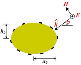
7 Elliptical Cloak Designs at Microwaves H E r H E r r H E PEC H E PEC c 7
8 Elliptical Cloak Designs at THz Frequencies 8

9 Scattering from Strips by Mathieu Functions 9

10 Mathieu Equation Two-dimentional Helmholtz Equation: where: Using the method of separation of variables we have: Radial Mathieu Equation The radial Mathieu equation has four kinds of solution as: Angular Mathieu Equation The angular Mathieu equation has the solution as: p, m can be even or odd 10

11 Formulation of the Scattering Problem Incident Electric Field Scattered Electric Field Incident Magnetic Field Scattered Magnetic Field Transmitted Electric Field Transmitted Magnetic Field 11

12 By applying boundary conditions : Boundary Conditions Sheet Impedance Boundary Condition Sheet Impedance Boundary Condition 12
13 Bistatic Scattering Width The two-dimensional bistatic cross section is defined as: Finally, we have: 13
14 Quasi-static Closed-form Condition In the quasi-static limit( ), the closed-form condition for a PEC elliptical cylinder under TM-polarized illumination can be derived as: And also, the closed-form condition for a dielectric elliptical cylinder under TM-polarized illumination can be derived as: 14
15 Surface Reactance Frequency Dispersion Frequency dispersion of the surface reactance for graphene monolayer and nanopatches with respect to the optimum required is found as: Required Reactance for Dielectric Ellipse Required Reactance for PEC Ellipse Required Reactance for Strip 15

16 Kubo Formula Surface Conductivity of Graphene Intraband Contributions Interband Contributions Z s 1 : charge of electron : temperature : energy : angular frequency : reduced Planck s constant : chemical potential : momentum relaxation time G. W. Hanson, Dyadic Green s functions and guided surface waves for a surface conductivity model of graphene, J. Appl. Phys., vol. 103, pp ,

17 Dielectric Elliptical Cylinder at THz Frequencies Geometry parameters are: The required reactance is found to be: The design parameters are: 17


18 Power Flow and Far-field Pattern Uncloaked Cloaked f= 3 THz 18


19 Electric Field Distribution Uncloaked f= 3 THz Cloaked 19


20 Closely Spaced and Overlapping Dielectric Elliptical Cylinders Uncloaked Cloaked l= 50 µm Uncloaked Cloaked f= 3 THz l= 48 µm 20


21 Cluster of Dielectric Elliptical Cylinders I Uncloaked l= 50 µm= 0.5 λ Cloaked g= 3 µm Uncloaked Cloaked f= 3 THz 21


22 Cluster of Dielectric Elliptical Cylinders II Uncloaked Cloaked g= 3 µm Uncloaked Cloaked f= 3 THz 22


23 Overlapping of Dielectric Elliptical Cylinders Uncloaked Cloaked l= 140 µm= 1.4 λ f= 3 THz Uncloaked Cloaked 23

24 Dielectric Elliptical Cylinder at Microwave Frequencies Geometry parameters are: The required reactance is found to be: The design parameters are: N= 8 H E r 24
25 Dielectric Elliptical Cylinder at Microwave Frequencies N= 3 Geometry parameters are: The required reactance is found to be: The design parameters are: H E r N= 3 N= 8 N= 8 25

26 Electric Field Distribution Uncloaked N= 8 r f= 3 GHz Cloaked 26
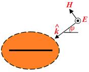
27 Strip (Degenerated Ellipse) A strip can be modeled as a degenerated ellipse Geometry parameters are: 27


28 Power Flow and Far-field Pattern Uncloaked Cloaked f= 3 THz 28

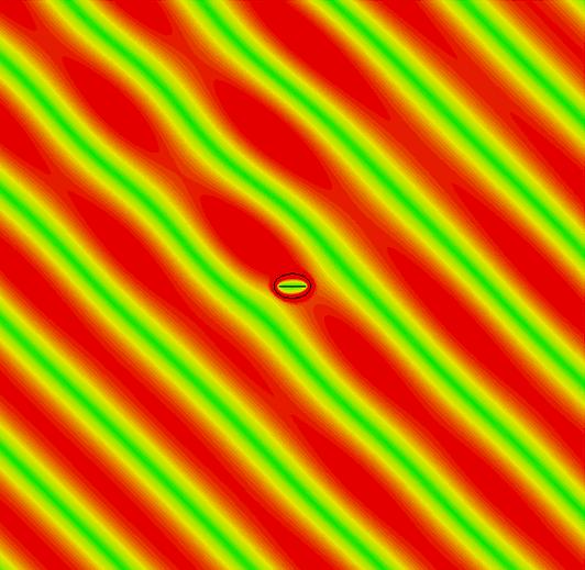
29 Electric Field Distribution Uncloaked Cloaked 29


30 Cloaking for Two Strips Uncloaked Cloaked f= 3 THz 30

31 Two Strips Horizontally Oriented f= 3 THz Uncloaked Cloaked 31


32 Two Strips with Overlapping Cloaks Uncloaked Cloaked f= 3 THz Uncloaked Cloaked g= 3.7 µm 32


33 Two Connected Strips Uncloaked Cloaked f= 3 THz Uncloaked Cloaked 33


34 Wire Dipole Antennas 34
35 Strip Dipole Antennas Here, we present the applicability of elliptically shaped metasurfaces in order to reduce the mutual coupling between two closely spaced antennas. First, we consider two strip dipole antennas resonating at f= 1 GHz and f= 5 GHz, which are separated by a short distance of d= λ/10 (at f= 5 GHz). (Case I) Second, we consider two strip dipole antennas resonating at f= 3.02 GHz and f= 3.33 GHz, which are separated by a short distance of d= λ/10 (at f= 3 GHz). (Case II) To present how the mutual blockage is overcome, we consider three different scenarios of isolated, uncloaked, and cloaked for each case. 35
 which resonate at f= 1 GHz")


36 Case I We consider Antenna I (isolated) and Antenna II (isolated) which resonate at f= 1 GHz and f= 5 GHz, respectively, with omni-directional radiation patterns as shown below. Each antenna is matched to a 75-Ω feed. Antenna I W= 4 mm Δ= 0.2 mm L= mm Antenna II W= 4 mm Δ= 0.2 mm L= 27.5 mm 36


37 Neighboring Uncloaked Dipole Antennas Now, the antennas are placed in close proximity to each other. The presence of Antenna II does not have much effect on Antenna I since its length is small compared to the wavelength of the resonance frequency of Antenna I, but Antenna I changes the matching characteristics and radiation pattern of Antenna II drastically. d= 6 mm f= 1 GHz f= 5 GHz 37

38 Cloaking 2-D Metallic Strip a 2-D Metallic Strip can be considered as a degenerated ellipse TM-polarized plane-wave excitation. 38


39 Cloaking 2-D Metallic Strip Uncloaked Cloaked 39
40 How to Cloak Antenna I? Since the length of Antenna I is 2.5 times the wavelength of Antenna II, therefore, we propose to use the analytical approach for infinite length as a good approximation to find the required metasursurface for this case. 40

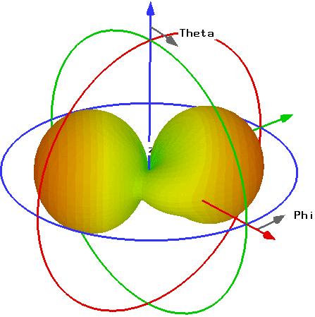
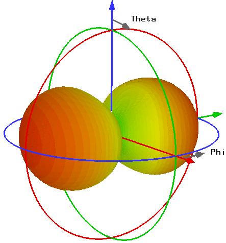
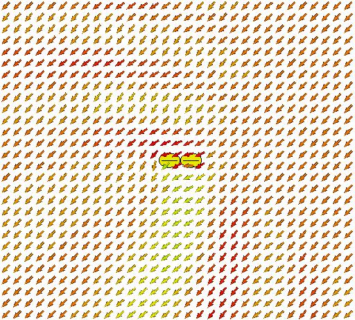
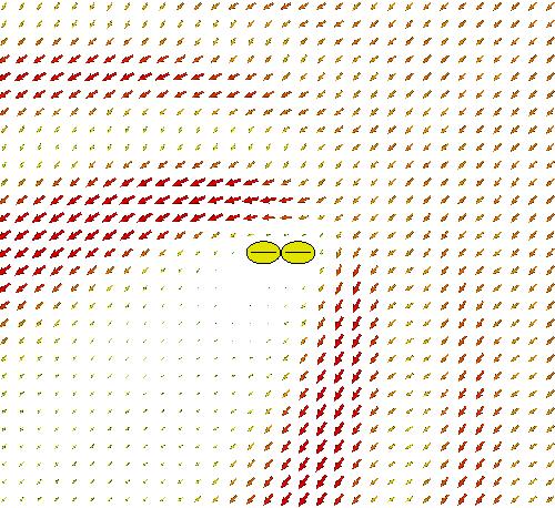
41 Neighboring Cloaked Dipole Antennas 3-D radiation patterns of Antenna I at 1 GHz (left) and Antenna II at 5 GHz (right) for the scenario, in which Antenna I is cloaked for the resonance frequency of Antenna II and the antennas are in close proximity. Antenna I f= 1 GHz f= 5 GHz Antenna II 41
 and")

42 2-D Gain Pattern Restoration of gain patterns at the first and second resonance frequency of Antenna I (1 GHz, 3 GHz) and resonance frequency of Antenna II f= 5 GHz Antenna I f= 1 GHz f= 3 GHz H-plane E-plane Antenna I Antenna I H-plane E-plane H-plane E-plane 42

43 Isolated Antenna I (Case II) First of all, we consider the antenna I (Isolated Case), which resonates at f= 3.02 GHz with an omni-directional radiation pattern as shown below. The S11 of the antenna along with its dimensions are shown below. The antenna is matched to a 75-Ω feed. W= 4 mm L= 45.8 mm Δ= 0.2 mm f= 3.02 GHz Δ L 43

44 Isolated Antenna II (Case II) Then, we consider the antenna II (Isolated Case), which resonates at f= 3.33 GHz with an omni-directional radiation pattern as illustrated below. The S11 of the antenna along with its dimensions are shown below. The antenna is matched to a 75-Ω feed. W= 4 mm L= 41.5 mm Δ= 0.2 mm f= 3.33 GHz Δ L 44

45 Neighboring Uncloaked Dipole Antennas Now, the antennas are placed in close proximity to each other. As expected, the presence of each of the antennas affects the radiation pattern of the other one drastically because the near-field distribution is changed, and therefore, the input reactance is changed remarkably. f= 3.02 GHz f= 3.33 GHz 45
46 Separated Cloaked Dipole Antennas To reduce the mutual coupling, we cover each dipole antenna with an elliptically shaped mantle cloak structure consisting of inductive vertical strips and a spacer between the strip and the metasurface. The presence of the spacer, and then, the cloak structure, changes the resonance frequency of the antenna. Therefore, we reduce the length of the antenna in order to provide good matching at the desired working frequency. On the other hand, the parameters of the cloak structure should be chosen in a way that each antenna is invisible at the resonance frequency of the other one. We have performed an appropriate optimization to minimize the 3-D total RCS of each dipole antenna under Transverse Magnetic (TM) plane-wave excitation. 46


47 Cloaked Dipole Antenna I In this slide, the antenna I covered with the spacer and the metasurface is presented. To achieve a good matching at the desired resonance frequency of 3.02 GHz, we reduced the length of the antenna from L= 45.8 mm to L= 41.4 mm. The S11 parameter, permittivity of the spacer, and also, the dimensions of the cloak structure are shown below. RCS L= 41.4 mm S11 Rogers RO3006 (Lossy) 47


48 Cloaked Dipole Antenna II In this slide, the antenna II covered with the spacer and the cloak design is presented. To achieve a good matching at the desired resonance frequency of 3.02 GHz, again, we reduced the length of the antenna from L= 41.5 mm to L= 38.8 mm. The S11 parameter, permittivity of the spacer, and also, the dimensions of the cloak structure are shown below. RCS L= 38.8 mm Rogers TMM 10i (Lossy) 48
49 Neighboring Cloaked Dipole Antennas The reflection coefficients at the input port of the Antenna I and the Antenna II in the cloaked case (the antennas are in close proximity to each other) are shown here. As can be seen, the impedance matching of the antennas are good near the resonant frequency of each isolated strip dipole antenna. Radiation patterns are: 49


50 Neighboring Cloaked Dipole Antennas f= GHz E-Plane f= GHz H-Plane f= GHz f= GHz 50


51 Conclusions An analytical approach has been proposed to cloak elliptical cylinders, and also, strips at microwave and low-thz frequencies by using conformal mantle cloak designs. Although the electromagnetic wave scattering of an elliptical cylinder is pertinent to the angle of incidence, it is shown that the cloak design is robust for any incident angle. The idea of cloaking strips has been utilized to reduce the mutual coupling between two strip dipole antennas. 51
CHAPTER 2 MICROSTRIP REFLECTARRAY ANTENNA AND PERFORMANCE EVALUATION
 43 CHAPTER 2 MICROSTRIP REFLECTARRAY ANTENNA AND PERFORMANCE EVALUATION 2.1 INTRODUCTION This work begins with design of reflectarrays with conventional patches as unit cells for operation at Ku Band in
Electromagnetics, Microwave Circuit and Antenna Design for Communications Engineering
 Electromagnetics, Microwave Circuit and Antenna Design for Communications Engineering Second Edition Peter Russer ARTECH HOUSE BOSTON LONDON artechhouse.com Contents Preface xvii Chapter 1 Introduction
SUPPLEMENTARY INFORMATION
 A full-parameter unidirectional metamaterial cloak for microwaves Bilinear Transformations Figure 1 Graphical depiction of the bilinear transformation and derived material parameters. (a) The transformation
Mantle cloaking for co-site radio-frequency antennas
 Mantle cloaking for co-site radio-frequency antennas Alessio Monti 1,*, Jason Soric 2, Mirko Barbuto 1, Davide Ramaccia 3, Stefano Vellucci 3, Fabrizio Trotta 4, Andrea Alù 2, Alessandro Toscano 3 and
ENHANCEMENT OF PRINTED DIPOLE ANTENNAS CHARACTERISTICS USING SEMI-EBG GROUND PLANE
 J. of Electromagn. Waves and Appl., Vol. 2, No. 8, 993 16, 26 ENHANCEMENT OF PRINTED DIPOLE ANTENNAS CHARACTERISTICS USING SEMI-EBG GROUND PLANE F. Yang, V. Demir, D. A. Elsherbeni, and A. Z. Elsherbeni
Efficient Metasurface Rectenna for Electromagnetic Wireless Power Transfer and Energy Harvesting
 Progress In Electromagnetics Research, Vol. 161, 35 40, 2018 Efficient Metasurface Rectenna for Electromagnetic Wireless Power Transfer and Energy Harvesting Mohamed El Badawe and Omar M. Ramahi * Abstract
Electromagnetic Band Gap Structures in Antenna Engineering
 Electromagnetic Band Gap Structures in Antenna Engineering FAN YANG University of Mississippi YAHYA RAHMAT-SAMII University of California at Los Angeles Hfl CAMBRIDGE Щ0 UNIVERSITY PRESS Contents Preface
Investigation of Board-Mounted Omni- Directional Antennas for WLAN- Applications
 Investigation of Board-Mounted Omni- Directional Antennas for WLAN- Applications Luis Quineche ISE Master Student EEE: Communications Engineering Index Description of Problem Thesis Task Background Theory
Frequency Tunable Low-Cost Microwave Absorber for EMI/EMC Application
 Progress In Electromagnetics Research Letters, Vol. 74, 47 52, 2018 Frequency Tunable Low-Cost Microwave Absorber for EMI/EMC Application Gobinda Sen * and Santanu Das Abstract A frequency tunable multi-layer
Keywords: Array antenna; Metamaterial structure; Microstrip antenna; Split ring resonator
 International Journal of Technology (2016) 4: 683-690 ISSN 2086-9614 IJTech 2016 LEFT-HANDED METAMATERIAL (LHM) STRUCTURE STACKED ON A TWO- ELEMENT MICROSTRIP ANTENNA ARRAY Fitri Yuli Zulkifli 1*, Nugroho
Monoconical RF Antenna
 Page 1 of 8 RF and Microwave Models : Monoconical RF Antenna Monoconical RF Antenna Introduction Conical antennas are useful for many applications due to their broadband characteristics and relative simplicity.
Design of Frequency and Polarization Tunable Microstrip Antenna
 Design of Frequency and Polarization Tunable Microstrip Antenna M. S. Nishamol, V. P. Sarin, D. Tony, C. K. Aanandan, P. Mohanan, K. Vasudevan Abstract A novel compact dual frequency microstrip antenna
Determination of Transmission and Reflection Parameters by Analysis of Square Loop Metasurface
 Determination of Transmission and Reflection Parameters by Analysis of Square Loop Metasurface Anamika Sethi #1, Rajni *2 #Research Scholar, ECE Department, MRSPTU, INDIA *Associate Professor, ECE Department,
INTERNATIONAL JOURNAL OF PURE AND APPLIED RESEARCH IN ENGINEERING AND TECHNOLOGY
 Prerna Saxena,, 2013; Volume 1(8): 46-53 INTERNATIONAL JOURNAL OF PURE AND APPLIED RESEARCH IN ENGINEERING AND TECHNOLOGY A PATH FOR HORIZING YOUR INNOVATIVE WORK STUDY OF PATCH ANTENNA ARRAY USING SINGLE
UNIVERSITI MALAYSIA PERLIS
 UNIVERSITI MALAYSIA PERLIS SCHOOL OF COMPUTER & COMMUNICATIONS ENGINEERING EKT 341 LABORATORY MODULE LAB 2 Antenna Characteristic 1 Measurement of Radiation Pattern, Gain, VSWR, input impedance and reflection
A. A. Kishk and A. W. Glisson Department of Electrical Engineering The University of Mississippi, University, MS 38677, USA
 Progress In Electromagnetics Research, PIER 33, 97 118, 2001 BANDWIDTH ENHANCEMENT FOR SPLIT CYLINDRICAL DIELECTRIC RESONATOR ANTENNAS A. A. Kishk and A. W. Glisson Department of Electrical Engineering
Optically reconfigurable balanced dipole antenna
 Loughborough University Institutional Repository Optically reconfigurable balanced dipole antenna This item was submitted to Loughborough University's Institutional Repository by the/an author. Citation:
A NOVEL DUAL-BAND PATCH ANTENNA FOR WLAN COMMUNICATION. E. Wang Information Engineering College of NCUT China
 Progress In Electromagnetics Research C, Vol. 6, 93 102, 2009 A NOVEL DUAL-BAND PATCH ANTENNA FOR WLAN COMMUNICATION E. Wang Information Engineering College of NCUT China J. Zheng Beijing Electro-mechanical
3. LITERATURE REVIEW. 3.1 The Planar Inverted-F Antenna.
 3. LITERATURE REVIEW The commercial need for low cost and low profile antennas for mobile phones has drawn the interest of many researchers. While wire antennas, like the small helix and quarter-wavelength
Compact Broadband End-Fire Antenna with Metamaterial Transmission Line
 Progress In Electromagnetics Research Letters, Vol. 73, 37 44, 2018 Compact Broadband End-Fire Antenna with Metamaterial Transmission Line Liang-Yuan Liu * and Jing-Qi Lu Abstract A broadband end-fire
Introduction: Planar Transmission Lines
 Chapter-1 Introduction: Planar Transmission Lines 1.1 Overview Microwave integrated circuit (MIC) techniques represent an extension of integrated circuit technology to microwave frequencies. Since four
Mutual Coupling between Two Patches using Ideal High Impedance Surface
 International Journal of Electronics and Communication Engineering. ISSN 0974-2166 Volume 4, Number 3 (2011), pp. 287-293 International Research Publication House http://www.irphouse.com Mutual Coupling
FDTD CHARACTERIZATION OF MEANDER LINE ANTENNAS FOR RF AND WIRELESS COMMUNICATIONS
 Progress In Electromagnetics Research, PIER 4, 85 99, 999 FDTD CHARACTERIZATION OF MEANDER LINE ANTENNAS FOR RF AND WIRELESS COMMUNICATIONS C.-W. P. Huang, A. Z. Elsherbeni, J. J. Chen, and C. E. Smith
A WIDEBAND RECTANGULAR MICROSTRIP ANTENNA WITH CAPACITIVE FEEDING
 A WIDEBAND RECTANGULAR MICROSTRIP ANTENNA WITH CAPACITIVE FEEDING Hind S. Hussain Department of Physics, College of Science, Al-Nahrain University, Baghdad, Iraq E-Mail: hindalrawi@yahoo.com ABSTRACT A
Chapter 2. Modified Rectangular Patch Antenna with Truncated Corners. 2.1 Introduction of rectangular microstrip antenna
 Chapter 2 Modified Rectangular Patch Antenna with Truncated Corners 2.1 Introduction of rectangular microstrip antenna 2.2 Design and analysis of rectangular microstrip patch antenna 2.3 Design of modified
A VARACTOR-TUNABLE HIGH IMPEDANCE SURFACE FOR ACTIVE METAMATERIAL ABSORBER
 Progress In Electromagnetics Research C, Vol. 43, 247 254, 2013 A VARACTOR-TUNABLE HIGH IMPEDANCE SURFACE FOR ACTIVE METAMATERIAL ABSORBER Bao-Qin Lin *, Shao-Hong Zhao, Qiu-Rong Zheng, Meng Zhu, Fan Li,
DUAL-BAND LOW PROFILE DIRECTIONAL ANTENNA WITH HIGH IMPEDANCE SURFACE REFLECTOR
 Progress In Electromagnetics Research Letters, Vol. 25, 67 75, 211 DUAL-BAND LOW PROFILE DIRECTIONAL ANTENNA WITH HIGH IMPEDANCE SURFACE REFLECTOR X. Mu *, W. Jiang, S.-X. Gong, and F.-W. Wang Science
EMG4066:Antennas and Propagation Exp 1:ANTENNAS MMU:FOE. To study the radiation pattern characteristics of various types of antennas.
 OBJECTIVES To study the radiation pattern characteristics of various types of antennas. APPARATUS Microwave Source Rotating Antenna Platform Measurement Interface Transmitting Horn Antenna Dipole and Yagi
ECSE 352: Electromagnetic Waves
 December 2008 Final Examination ECSE 352: Electromagnetic Waves 09:00 12:00, December 15, 2008 Examiner: Zetian Mi Associate Examiner: Andrew Kirk Student Name: McGill ID: Instructions: This is a CLOSED
Microwave and optical systems Introduction p. 1 Characteristics of waves p. 1 The electromagnetic spectrum p. 3 History and uses of microwaves and
 Microwave and optical systems Introduction p. 1 Characteristics of waves p. 1 The electromagnetic spectrum p. 3 History and uses of microwaves and optics p. 4 Communication systems p. 6 Radar systems p.
Design of Frequency Selective Band Stop Shield Using Analytical Method
 7 Design of Frequency Selective Band Stop Shield Using Analytical Method Mahmoud Fallah, Alireza Ghayekhloo, Ali Abdolali 3-3 Department of Electrical Engineering, Iran University of Science and Technology
BACK RADIATION REDUCTION IN PATCH ANTENNAS USING PLANAR SOFT SURFACES
 Progress In Electromagnetics Research Letters, Vol. 6, 123 130, 2009 BACK RADIATION REDUCTION IN PATCH ANTENNAS USING PLANAR SOFT SURFACES E. Rajo-Iglesias, L. Inclán-Sánchez, and Ó. Quevedo-Teruel Department
RF simulations with COMSOL
 RF simulations with COMSOL ICPS 217 Politecnico di Torino Aug. 1 th, 217 Gabriele Rosati gabriele.rosati@comsol.com 3 37.93.8 Copyright 217 COMSOL. Any of the images, text, and equations here may be copied
DESIGN OF A PLANAR MONOPOLE ULTRA WIDE BAND PATCH ANTENNA
 International Journal of Electrical and Electronics Engineering Research (IJEEER) ISSN(P): 2250-155X; ISSN(E): 2278-943X Vol. 4, Issue 1, Feb 2014, 47-52 TJPRC Pvt. Ltd. DESIGN OF A PLANAR MONOPOLE ULTRA
Projects in microwave theory 2017
 Electrical and information technology Projects in microwave theory 2017 Write a short report on the project that includes a short abstract, an introduction, a theory section, a section on the results and
Loss Reduction in Microstrip Antenna Using Different Methods
 Loss Reduction in Microstrip Antenna Using Different Methods Alpesh Nema 1#, D.K. Raghuvanshi 2#, Priyanka Raghuvanshi 3* # Department of Electronics & Communication Engineering MANIT-Bhopal, India. *
QUALITY FACTOR FOR ANTENNAS (A TUTORIAL)
") EuCAP-2014, The Hague, Netherlands QUALITY FACTOR FOR ANTENNAS (A TUTORIAL) Arthur D. Yaghjian (EM Consultant, USA) a.yaghjian@comcast.net Mats Gustafsson (Lund U., Sweden) B. Lars G. Jonsson (KTH, Sweden)
EuCAP-2014, The Hague, Netherlands QUALITY FACTOR FOR ANTENNAS (A TUTORIAL) Arthur D. Yaghjian (EM Consultant, USA) a.yaghjian@comcast.net Mats Gustafsson (Lund U., Sweden) B. Lars G. Jonsson (KTH, Sweden)
6464(Print), ISSN (Online) ENGINEERING Volume & 3, Issue TECHNOLOGY 3, October- December (IJECET) (2012), IAEME
, ISSN (Online) ENGINEERING Volume & 3, Issue TECHNOLOGY 3, October- December (IJECET) (2012), IAEME") International INTERNATIONAL Journal of Electronics JOURNAL and Communication OF ELECTRONICS Engineering AND & Technology COMMUNICATION (IJECET), ISSN 0976 6464(Print), ISSN 0976 6472(Online) ENGINEERING
International INTERNATIONAL Journal of Electronics JOURNAL and Communication OF ELECTRONICS Engineering AND & Technology COMMUNICATION (IJECET), ISSN 0976 6464(Print), ISSN 0976 6472(Online) ENGINEERING
A Dual-Polarized MIMO Antenna with EBG for 5.8 GHz WLAN Application
 Progress In Electromagnetics Research Letters, Vol. 51, 15 2, 215 A Dual-Polarized MIMO Antenna with EBG for 5.8 GHz WLAN Application Xiaoyan Zhang 1, 2, *, Xinxing Zhong 1,BinchengLi 3, and Yiqiang Yu
CHAPTER 6 CARBON NANOTUBE AND ITS RF APPLICATION
 CHAPTER 6 CARBON NANOTUBE AND ITS RF APPLICATION 6.1 Introduction In this chapter we have made a theoretical study about carbon nanotubes electrical properties and their utility in antenna applications.
Performance Analysis of Different Ultra Wideband Planar Monopole Antennas as EMI sensors
 International Journal of Electronics and Communication Engineering. ISSN 09742166 Volume 5, Number 4 (2012), pp. 435445 International Research Publication House http://www.irphouse.com Performance Analysis
COMPACT FRACTAL MONOPOLE ANTENNA WITH DEFECTED GROUND STRUCTURE FOR WIDE BAND APPLICATIONS
 COMPACT FRACTAL MONOPOLE ANTENNA WITH DEFECTED GROUND STRUCTURE FOR WIDE BAND APPLICATIONS 1 M V GIRIDHAR, 2 T V RAMAKRISHNA, 2 B T P MADHAV, 3 K V L BHAVANI 1 M V REDDIAH BABU, 1 V SAI KRISHNA, 1 G V
L-BAND COPLANAR SLOT LOOP ANTENNA FOR INET APPLICATIONS
 L-BAND COPLANAR SLOT LOOP ANTENNA FOR INET APPLICATIONS Jeyasingh Nithianandam Electrical and Computer Engineering Department Morgan State University, 500 Perring Parkway, Baltimore, Maryland 5 ABSTRACT
A Pin-Loaded Microstrip Patch Antenna with the Ability to Suppress Surface Wave Excitation
 Progress In Electromagnetics Research C, Vol. 62, 131 137, 2016 A Pin-Loaded Microstrip Patch Antenna with the Ability to Suppress Surface Wave Excitation Ayed R. AlAjmi and Mohammad A. Saed * Abstract
COAXIAL / CIRCULAR HORN ANTENNA FOR A STANDARD
 COAXIAL / CIRCULAR HORN ANTENNA FOR 802.11A STANDARD Petr Všetula Doctoral Degree Programme (1), FEEC BUT E-mail: xvsetu00@stud.feec.vutbr.cz Supervised by: Zbyněk Raida E-mail: raida@feec.vutbr.cz Abstract:
Microwave switchable frequency selective surface with high quality factor resonance and low polarization sensitivity
 263 Microwave switchable frequency selective surface with high quality factor resonance and low polarization sensitivity Victor Dmitriev and Marcelo N. Kawakatsu Department of Electrical Engineering, Federal
Analysis of an air-spaced patch antenna near 1800 MHz
 Marquette University e-publications@marquette Master's Theses (2009 -) Dissertations, Theses, and Professional Projects Analysis of an air-spaced patch antenna near 1800 MHz Hermine Nathalie Akouemo Kengmo
CONTENTS. Note Concerning the Numbering of Equations, Figures, and References; Notation, xxi. A Bridge from Mathematics to Engineering in Antenna
 CONTENTS Note Concerning the Numbering of Equations, Figures, and References; Notation, xxi Introduction: Theory, 1 A Bridge from Mathematics to Engineering in Antenna Isolated Antennas 1. Free Oscillations,
TOPIC 2 WAVEGUIDE AND COMPONENTS
 TOPIC 2 WAVEGUIDE AND COMPONENTS COURSE LEARNING OUTCOME (CLO) CLO1 Explain clearly the generation of microwave, the effects of microwave radiation and the propagation of electromagnetic in a waveguide
Compact and Low Profile MIMO Antenna for Dual-WLAN-Band Access Points
 Progress In Electromagnetics Research Letters, Vol. 67, 97 102, 2017 Compact and Low Profile MIMO Antenna for Dual-WLAN-Band Access Points Xinyao Luo *, Jiade Yuan, and Kan Chen Abstract A compact directional
5 Design of Feed and Feed Network for Microstrip Antennas
 5 Design of Feed and Feed Network for Microstrip Antennas 5.1 Introduction The microstrip antenna can be excited either by a coaxial probe or by a microstrip line. It can also be excited indirectly using
AN APPROACH TO DESIGN AND OPTIMIZATION OF WLAN PATCH ANTENNAS FOR WI-FI APPLICATIONS
 IJWC ISSN: 31-3559 & E-ISSN: 31-3567, Volume 1, Issue, 011, pp-09-14 Available online at http://www.bioinfo.in/contents.php?id109 AN APPROACH TO DESIGN AND OPTIMIZATION OF WLAN PATCH ANTENNAS FOR WI-FI
Slot Antennas For Dual And Wideband Operation In Wireless Communication Systems
 Slot Antennas For Dual And Wideband Operation In Wireless Communication Systems Abdelnasser A. Eldek, Cuthbert M. Allen, Atef Z. Elsherbeni, Charles E. Smith and Kai-Fong Lee Department of Electrical Engineering,
A Compact Miniaturized Frequency Selective Surface with Stable Resonant Frequency
 Progress In Electromagnetics Research Letters, Vol. 62, 17 22, 2016 A Compact Miniaturized Frequency Selective Surface with Stable Resonant Frequency Ning Liu 1, *, Xian-Jun Sheng 2, and Jing-Jing Fan
RF AND MICROWAVE ENGINEERING
 RF AND MICROWAVE ENGINEERING FUNDAMENTALS OF WIRELESS COMMUNICATIONS Frank Gustrau Dortmund University of Applied Sciences and Arts, Germany WILEY A John Wiley & Sons, Ltd., Publication Preface List of
Study of Microstrip Antenna Behavior with Metamaterial Substrate of SRR Type Combined with TW
 Study of Microstrip Antenna Behavior with Metamaterial Substrate of SRR Type Combined with TW JOSÉ LUCAS DA SILVA 1, HUMBERTO CÉSAR CHAVES FERNANDES, HUMBERTO DIONÍSIO DE ANDRADE 3 1, Department of Electrical
STUDY OF THIN RESISTIVELY LOADED FSS BASED MICROWAVE ABSORBERS
 STUDY OF THIN RESISTIVELY LOADED FSS BASED MICROWAVE ABSORBERS by SITI NORMI ZABRI B. Eng (Hons), MSc. (Eng) A thesis submitted in fulfilment of the requirements for the degree of DOCTOR OF PHILOSOPHY
Electromagnetic Analysis of Propagation and Scattering Fields in Dielectric Elliptic Cylinder on Planar Ground
 PIERS ONLINE, VOL. 5, NO. 7, 2009 684 Electromagnetic Analysis of Propagation and Scattering Fields in Dielectric Elliptic Cylinder on Planar Ground Yasumitsu Miyazaki 1, Tadahiro Hashimoto 2, and Koichi
A Wideband Magneto-Electric Dipole Antenna with Improved Feeding Structure
 ADVANCED ELECTROMAGNETICS, VOL. 5, NO. 2, AUGUST 2016 ` A Wideband Magneto-Electric Dipole Antenna with Improved Feeding Structure Neetu Marwah 1, Ganga P. Pandey 2, Vivekanand N. Tiwari 1, Sarabjot S.
Optimization of a Wide-Band 2-Shaped Patch Antenna for Wireless Communications
 Optimization of a Wide-Band 2-Shaped Patch Antenna for Wireless Communications ALI EL ALAMI 1, SAAD DOSSE BENNANI 2, MOULHIME EL BEKKALI 3, ALI BENBASSOU 4 1, 3, 4 University Sidi Mohamed Ben Abdellah
National Severe Storm Laboratory, NOAA Paper ID:
 Dual-Polarized Radiating Elements Based on Electromagnetic Dipole Concept Ridhwan Khalid Mirza 1, Yan (Rockee) Zhang 1, Dusan Zrnic 2 and Richard Doviak 2 1 Intelligent Aerospace Radar Team, Advanced Radar
Design of Frequency Selective Surface Radome over a Frequency Range
 Vol.2, Issue.3, May-June 2012 pp-1231-1236 ISSN: 2249-6645 Design of Frequency Selective Surface Radome over a Frequency Range K. Renu 1, K.V. V. Prasad 2, S. Saradha Rani 3, A. Gayatri 4 1, 3, 4 (Department
TRANSMITTING ANTENNA WITH DUAL CIRCULAR POLARISATION FOR INDOOR ANTENNA MEASUREMENT RANGE
 TRANSMITTING ANTENNA WITH DUAL CIRCULAR POLARISATION FOR INDOOR ANTENNA MEASUREMENT RANGE Michal Mrnka, Jan Vélim Doctoral Degree Programme (2), FEEC BUT E-mail: xmrnka01@stud.feec.vutbr.cz, velim@phd.feec.vutbr.cz
ANALYSIS AND DESIGN OF DUAL BAND HIGH DIRECTIVITY EBG RESONATOR ANTENNA USING SQUARE LOOP FSS AS SUPERSTRATE LAYER
 Progress In Electromagnetics Research, PIER 70, 1 20, 2007 ANALYSIS AND DESIGN OF DUAL BAND HIGH DIRECTIVITY EBG RESONATOR ANTENNA USING SQUARE LOOP FSS AS SUPERSTRATE LAYER A. Pirhadi Department of Electrical
A RECONFIGURABLE HYBRID COUPLER CIRCUIT FOR AGILE POLARISATION ANTENNA
 A RECONFIGURABLE HYBRID COUPLER CIRCUIT FOR AGILE POLARISATION ANTENNA F. Ferrero (1), C. Luxey (1), G. Jacquemod (1), R. Staraj (1), V. Fusco (2) (1) Laboratoire d'electronique, Antennes et Télécommunications
ANALYSIS OF ELECTRICALLY SMALL SIZE CONICAL ANTENNAS. Y. K. Yu and J. Li Temasek Laboratories National University of Singapore Singapore
 Progress In Electromagnetics Research Letters, Vol. 1, 85 92, 2008 ANALYSIS OF ELECTRICALLY SMALL SIZE CONICAL ANTENNAS Y. K. Yu and J. Li Temasek Laboratories National University of Singapore Singapore
DEVELOPMENT OF AN ULTRA-WIDEBAND LOW- PROFILE WIDE SCAN ANGLE PHASED ARRAY ANTENNA
 DEVELOPMENT OF AN ULTRA-WIDEBAND LOW- PROFILE WIDE SCAN ANGLE PHASED ARRAY ANTENNA DISSERTATION Presented in Partial Fulfillment of the Requirements for the Degree Doctor of Philosophy in the Graduate
INDUCTIVE TRI-BAND DOUBLE ELEMENT FSS FOR SPACE APPLICATIONS
 Progress In Electromagnetics Research C, Vol. 18, 87 101, 2011 INDUCTIVE TRI-BAND DOUBLE ELEMENT FSS FOR SPACE APPLICATIONS D. Ramaccia and A. Toscano Department of Applied Electronics University of Rome
WIRELESS power transfer through coupled antennas
 3442 IEEE TRANSACTIONS ON ANTENNAS AND PROPAGATION, VOL. 58, NO. 11, NOVEMBER 2010 Fundamental Aspects of Near-Field Coupling Small Antennas for Wireless Power Transfer Jaechun Lee, Member, IEEE, and Sangwook
ELECTROMAGNETICS AREA
 ELECTROMAGNETICS AREA School of Electrical, Computer and Energy Engineering Arizona State University Constantine A. Balanis Regents Professor of EE What is Electromagnetics Electromagnetics is the study
CHAPTER 5 PRINTED FLARED DIPOLE ANTENNA
 CHAPTER 5 PRINTED FLARED DIPOLE ANTENNA 5.1 INTRODUCTION This chapter deals with the design of L-band printed dipole antenna (operating frequency of 1060 MHz). A study is carried out to obtain 40 % impedance
Antenna Design: Simulation and Methods
 Antenna Design: Simulation and Methods Radiation Group Signals, Systems and Radiocommunications Department Universidad Politécnica de Madrid Álvaro Noval Sánchez de Toca e-mail: anoval@gr.ssr.upm.es Javier
A HOLLY-LEAF-SHAPED MONOPOLE ANTENNA WITH LOW RCS FOR UWB APPLICATION
 Progress In Electromagnetics Research, Vol. 117, 35 50, 2011 A HOLLY-LEAF-SHAPED MONOPOLE ANTENNA WITH LOW RCS FOR UWB APPLICATION H.-Y. Xu *, H. Zhang, K. Lu, and X.-F. Zeng Missile Institute of Airforce
Compact Electric Antennas
 Sensor and Simulation Notes Note 500 August 2005 Compact Electric Antennas Carl E. Baum University of New Mexico Department of Electrical and Computer Engineering Albuquerque New Mexico 87131 Abstract
SCATTERING POLARIMETRY PART 1. Dr. A. Bhattacharya (Slide courtesy Prof. E. Pottier and Prof. L. Ferro-Famil)
") SCATTERING POLARIMETRY PART 1 Dr. A. Bhattacharya (Slide courtesy Prof. E. Pottier and Prof. L. Ferro-Famil) 2 That s how it looks! Wave Polarisation An electromagnetic (EM) plane wave has time-varying
SCATTERING POLARIMETRY PART 1 Dr. A. Bhattacharya (Slide courtesy Prof. E. Pottier and Prof. L. Ferro-Famil) 2 That s how it looks! Wave Polarisation An electromagnetic (EM) plane wave has time-varying
MAGNETO-DIELECTRIC COMPOSITES WITH FREQUENCY SELECTIVE SURFACE LAYERS
 MAGNETO-DIELECTRIC COMPOSITES WITH FREQUENCY SELECTIVE SURFACE LAYERS M. Hawley 1, S. Farhat 1, B. Shanker 2, L. Kempel 2 1 Dept. of Chemical Engineering and Materials Science, Michigan State University;
Experiment 12: Microwaves
 MASSACHUSETTS INSTITUTE OF TECHNOLOGY Department of Physics 8.02 Spring 2005 OBJECTIVES Experiment 12: Microwaves To observe the polarization and angular dependence of radiation from a microwave generator
The Basics of Patch Antennas, Updated
 The Basics of Patch Antennas, Updated By D. Orban and G.J.K. Moernaut, Orban Microwave Products www.orbanmicrowave.com Introduction This article introduces the basic concepts of patch antennas. We use
arxiv:physics/ v1 [physics.optics] 28 Sep 2005
![arxiv:physics/ v1 [physics.optics] 28 Sep 2005](/thumbs/91/105523130.jpg "arxiv:physics/ v1 [physics.optics] 28 Sep 2005") Near-field enhancement and imaging in double cylindrical polariton-resonant structures: Enlarging perfect lens Pekka Alitalo, Stanislav Maslovski, and Sergei Tretyakov arxiv:physics/0509232v1 [physics.optics]
Near-field enhancement and imaging in double cylindrical polariton-resonant structures: Enlarging perfect lens Pekka Alitalo, Stanislav Maslovski, and Sergei Tretyakov arxiv:physics/0509232v1 [physics.optics]
ANTENNAS. I will mostly be talking about transmission. Keep in mind though, whatever is said about transmission is true of reception.
 Reading 37 Ron Bertrand VK2DQ http://www.radioelectronicschool.com ANTENNAS The purpose of an antenna is to receive and/or transmit electromagnetic radiation. When the antenna is not connected directly
DESIGN OF MID-BAND FREQUENCY PATCH ANTENNA FOR 5G APPLICATIONS
 DESIGN OF MID-BAND FREQUENCY PATCH ANTENNA FOR 5G APPLICATIONS HARINI. D 1, JAGADESHWAR. V 2, MOHANAPRIYA. E 3, SHERIBA. T.S 4 1,2,3Student, Dept. of ECE Engineering, Valliammai Engineering College, Tamil
ANALYSIS OF EPSILON-NEAR-ZERO METAMATE- RIAL SUPER-TUNNELING USING CASCADED ULTRA- NARROW WAVEGUIDE CHANNELS
 Progress In Electromagnetics Research M, Vol. 14, 113 121, 21 ANALYSIS OF EPSILON-NEAR-ZERO METAMATE- RIAL SUPER-TUNNELING USING CASCADED ULTRA- NARROW WAVEGUIDE CHANNELS J. Bai, S. Shi, and D. W. Prather
MINIATURIZED ANTENNAS FOR COMPACT SOLDIER COMBAT SYSTEMS
 MINIATURIZED ANTENNAS FOR COMPACT SOLDIER COMBAT SYSTEMS Iftekhar O. Mirza 1*, Shouyuan Shi 1, Christian Fazi 2, Joseph N. Mait 2, and Dennis W. Prather 1 1 Department of Electrical and Computer Engineering
DESIGN AND MODELING OF PLANAR LENS ANTENNA ELEMENT IN X-BAND APPLICATIONS
 VOL. 1, NO 19, OCTOBER, 215 ISSN 1819-668 26-215 Asian Research Publishing Network (ARPN). All rights reserved. DESIGN AND MODELING OF PLANAR LENS ANTENNA ELEMENT IN X-BAND APPLICATIONS Abdisamad A. Awaleh,
Microstrip Antennas Loaded with Shorting Post
 Engineering, 2009, 1, 1-54 Published Online June 2009 in SciRes (http://www.scirp.org/journal/eng/). Microstrip Antennas Pradeep Kumar, G. Singh Department of Electronics and Communication Engineering,
By choosing to view this document, you agree to all provisions of the copyright laws protecting it.
 Pekka Alitalo, Frédéric Bongard, Juan Mosig, and Sergei Tretyakov. 2009. Transmission line lens antenna with embedded source. In: Proceedings of the 3rd European Conference on Antennas and Propagation
A Method for Determining Optimal EBG Reflection Phase for Low Profile Dipole Antennas
 IEEE TRANSACTIONS ON ANTENNAS AND PROPAGATION, VOL. 61, NO. 5, MAY 2013 2411 A Method for Determining Optimal EBG Reflection Phase for Low Profile Dipole Antennas Ian T. McMichael, Member, IEEE, Amir I.
Evaluating the Electromagnetic Surface Wave of High Impedance Structures by Monopole Antenna and Application for Patch Antennas at Q Band
 International Journal of Electromagnetics and Applications 2016, 6(1): 1-6 DOI: 10.5923/j.ijea.20160601.01 Evaluating the Electromagnetic Surface Wave of High Impedance Structures by Monopole Antenna and
Analysis of Microstrip Circuits Using a Finite-Difference Time-Domain Method
 Analysis of Microstrip Circuits Using a Finite-Difference Time-Domain Method M.G. BANCIU and R. RAMER School of Electrical Engineering and Telecommunications University of New South Wales Sydney 5 NSW
Antennas Prof. Girish Kumar Department of Electrical Engineering Indian Institute of Technology, Bombay. Module 2 Lecture - 10 Dipole Antennas-III
 Antennas Prof. Girish Kumar Department of Electrical Engineering Indian Institute of Technology, Bombay Module 2 Lecture - 10 Dipole Antennas-III Hello, and welcome to todays lecture on Dipole Antenna.
Antennas 1. Antennas
 Antennas Antennas 1! Grading policy. " Weekly Homework 40%. " Midterm Exam 30%. " Project 30%.! Office hour: 3:10 ~ 4:00 pm, Monday.! Textbook: Warren L. Stutzman and Gary A. Thiele, Antenna Theory and
EC Transmission Lines And Waveguides
 EC6503 - Transmission Lines And Waveguides UNIT I - TRANSMISSION LINE THEORY A line of cascaded T sections & Transmission lines - General Solution, Physical Significance of the Equations 1. Define Characteristic
Mutual Coupling Reduction of Micro strip antenna array by using the Electromagnetic Band Gap structures
 Mutual Coupling Reduction of Micro strip antenna array by using the Electromagnetic Band Gap structures A.Rajasekhar 1, K.Vara prasad 2 1M.tech student, Dept. of electronics and communication engineering,
Inset Fed Microstrip Patch Antenna for X-Band Applications
 Inset Fed Microstrip Patch Antenna for X-Band Applications Pradeep H S Dept.of ECE, Siddaganga Institute of Technology, Tumakuru, Karnataka. Abstract Microstrip antennas play an important role in RF Communication.
Microwave Patch Antenna with Circular Polarization for Environmental Measurement
 Microwave Patch Antenna with Circular Polarization for Environmental Measurement Yumi Takizawa and Atsushi Fukasawa Institute of Statistical Mathematics Research Organization of Information and Systems
FILTERING ANTENNAS: SYNTHESIS AND DESIGN
 FILTERING ANTENNAS: SYNTHESIS AND DESIGN Deepika Agrawal 1, Jagadish Jadhav 2 1 Department of Electronics and Telecommunication, RCPIT, Maharashtra, India 2 Department of Electronics and Telecommunication,
DIELECTRIC RESONATOR ANTENNA MOUNTED ON A CIRCULAR CYLINDRICAL GROUND PLANE
 Progress In Electromagnetics Research B, Vol. 19, 427 444, 21 DIELECTRIC RESONATOR ANTENNA MOUNTED ON A CIRCULAR CYLINDRICAL GROUND PLANE S. H. Zainud-Deen, H. A. Malhat, and K. H. Awadalla Faculty of
Design of CPW Fed Ultra wideband Fractal Antenna and Backscattering Reduction
 Journal of Microwaves, Optoelectronics and Electromagnetic Applications, Vol. 9, No. 1, June 2010 10 Design of CPW Fed Ultra wideband Fractal Antenna and Backscattering Reduction Raj Kumar and P. Malathi
Determination of the Generalized Scattering Matrix of an Antenna From Characteristic Modes
 4848 IEEE TRANSACTIONS ON ANTENNAS AND PROPAGATION, VOL. 61, NO. 9, SEPTEMBER 2013 Determination of the Generalized Scattering Matrix of an Antenna From Characteristic Modes Yoon Goo Kim and Sangwook Nam
Broadband low cross-polarization patch antenna
 RADIO SCIENCE, VOL. 42,, doi:10.1029/2006rs003595, 2007 Broadband low cross-polarization patch antenna Yong-Xin Guo, 1 Kah-Wee Khoo, 1 Ling Chuen Ong, 1 and Kwai-Man Luk 2 Received 27 November 2006; revised