You may view our Appareo Stratus sales information at or contact
|
|
|
- Maurice Harmon
- 6 years ago
- Views:
Transcription
1 4 March 2017 RST Engineering Downwind Court Grass Valley CA voice only APPAREO INFORMATION PACKET Thank you for requesting the information packet on the Appareo line of products. We have assembled the most useful documents into this packet. If you have any questions, please feel free to contact us ( works best). You may view our Appareo Stratus sales information at or contact PAGE 2. The entire Appareo Product Reference document showing all products applicable to general aviation aircraft. PAGE 9. The ESG specific product reference document. PAGE 13. The ESG technical product specifications. PAGE 16. The full ESG installation manual. PAGE 64. The 2i ADS-B / AHRS product reference document PAGE 69. The 2i installation manual PAGE 76. Appareo STC document from the FAA PAGE 78. The approval from Appareo for permission to use the STC for their products. PAGE 80. The FAA policy regarding ADS-B installations. Some web sites that you may find interesting and/or informative: Jim Weir VP Engineering, RST


2 PRODUCT REFERENCE GUIDE
 Strain Relief Backshell")
3 STRATUS ESG Certified ADS-B OUT 1090 ES Transponder Built-in WAAS GPS GPS Antenna Included Stratus ESG Kit P/N: Includes: Certified Transponder WAAS GPS Antenna Stratus ESG Installation Kit Rack and Backplate 37 Pin DSUB Connector RF TNC Passthrough Adapter RF BNC Passthrough Adapter Screws (6) Strain Relief Backshell

 Female 9 Pin DSUB connector BNC Jack to Blind Mate")
4 STRATUS 2I Non-Certified ADS-B IN Same feature set as Stratus 2S Requires connection to Stratus ESG No battery Stratus 2i Kit P/N: Includes: Stratus 2i Module (P/N ) Stratus 2i Installation Kit RF Interface cable (P/N ) Power/Serial cable (P/N ) Female 9 Pin DSUB connector BNC Jack to Blind Mate Adapter
5 INTERFACE KIT FOR STRATUS PORTABLES Continuous power to Stratus portables Access to the ADS-B and GPS antennas mounted outside the aircraft Two kits because of different power connector, depending on Stratus model Interface Kit for Stratus Portables P/N: (Stratus 1S/2S) P/N: (Stratus 2) Includes: Power/Serial Interface Cable (USB Micro B for Stratus 2; USB Type C for Stratus 1S/2S) RF Interface Cable Connector plate kit 9 Pin DSUB connector w/strain relief (shown on plate) BNC connector (connects to back of ESG) BNC jack to blind mate adapter
6 Stratus 2i Installation BNC Jack to Blind Mate Max 3 Ft 20 AWG RF Interface Cable Power/Serial Interface Cable

7 Interface Kit Installation Max 3 Ft 20 AWG BNC Jack to Blind Mate RF Interface Cable Power/Serial Interface Cable
8


9 ADS-B IN/OUT ADS-B SIMPLIFIED 1090 ES Transponder Built-In WAAS GPS GPS Antenna Included


10 $2,995 READY FOR TAKEOFF REPLACE YOUR OLD TRANSPONDER AND BE ADS-B COMPLIANT FOR COMPLIANCE IN ONE BOX Stratus ESG is a TSO certified transponder that provides 2020 compliance in one box. Comply with the ADS-B mandate by replacing your old transponder, and get an upgrade that feels like an upgrade ES Transponder Built-In WAAS GPS GPS Antenna Included SIMPLE, LOW-COST INSTALLATION Designed with the common 1.65 tall form factor, it s an easy replacement for your existing transponder. Here s what to consider for install time: 1. Replace old transponder in panel 2. Install GPS antenna (included in kit) 3. Reuse existing transponder antenna 4. Reuse existing altitude encoder
 that was designed to work only with Stratus ESG.")


11 $3,495 THE ULTIMATE ADS-B EXPERIENCE The Stratus ESGi kit includes the certified transponder and a noncertified ADS-B receiver (Stratus 2i) that was designed to work only with Stratus ESG. STRATUS ESG FEATURES ADS-B Out P 1090 ES Transponder P Built-In WAAS GPS P GPS Antenna Included P Stratus 2i has the same feature set as Stratus 2S, but without the battery or internal antennas. When connected to Stratus ESG, this receiver provides the same industry-leading ADS-B and AHRS experience on ForeFlight Mobile that pilots have come to expect from the Stratus product family. STRATUS 2i FEATURES ADS-B In Subscription-Free Weather Dual-Band ADS-B Traffic Backup Attitude (AHRS) Flight Data Recorder Pressure Altitude Sensor P P P P P P appareo.com/stratus
12

13 STRATUS ESG SPECIFICATIONS FEATURES 1090 ES (Mode S extended squitter) Built-in WAAS GPS Meets global mandates for ADS-B Out transponders Push-button operation Easy-to-use interface Pressure altitude monitor TECHNICAL SPECIFICATIONS Cooling Input Environmental Compliance Software Compliance Hardware Compliance No fan required DO-160G DO-178B Level C DO-254 Level C TSO Compliance C112e (Level 2els, Class 1) C145d (Class Beta 1 GPS/WAAS) C166b (Class B1S) Display Transmitter Power OLED 310 W Bezel Height Bezel Width Depth Weight 1.69 in. (43 mm) 6.38 in. (162 mm) in. (273 mm) front of panel to connector backshell 3.29 lbs. (1.49 kg) including rack and connectors Operating Temperature -20 C to 55 C Storage Temperature -55 C to 85 C Power Input 9.0 to 36.0 VDC, 15 W typical DIMENSIONS 9.21 in. ( mm) 9.69 in. (246.1 mm) in. (273 mm) 1.69 in. (43 mm) 1.69 in. (43 mm) 6.38 in. (162 mm) 1810 NDSU Research Circle N Fargo, ND APPAREO.COM/STRATUS
14 STRATUS ESG 2020 COMPLIANCE IN ONE BOX Stratus ESG is a TSO certified transponder that provides 2020 compliance in one box. It s a 1090 MHz extended squitter (ES) transponder with built-in WAAS GPS. Designed to replace legacy transponders, Stratus ESG is a solid state transmitter that provides 310 watts nominal power output. Its modern keypad makes entering a squawk code easy. The convenient VFR button minimizes pilot keystrokes. SIMPLE INSTALLATION Stratus ESG is a form-factor replacement for existing transponders such as the popular KT 76A/C * so installation is more time-efficient compared to remote boxes that need to be integrated with your old transponder. A TSO d WAAS GPS antenna is included in the kit, and Stratus ESG can reuse an existing transponder antenna. It also accepts both serial and parallel (e.g. Gray code) inputs, so you can reuse most altitude encoders. WHAT TO CONSIDER WHEN ESTIMATING INSTALLATION Replace old transponder in panel Reuse existing transponder antenna Reuse existing altitude encoder Install WAAS GPS antenna (included in the kit) FEATURES 1090ES (Mode S extended squitter) Built-in WAAS GPS Meets global mandates for ADS-B Out transponders Push-button operation Easy-to-use interface Pressure altitude monitor STRATUS ESG TECHNICAL SPECS Bezel Height Bezel Width Depth Weight 1.69 in. (43 mm) 6.38 in. (162 mm) in. (273 mm) front of panel to connector backshell 3.29 lbs. (1.49 kg) including rack and connectors Operating Temperature -20 C to 55 C Storage Temperature -55 C to 85 C Power Input Cooling Input 9.0 to 36.0 VDC, 15 W typical No fan required Environmental Compliance DO-160G Software Compliance Hardware Compliance DO-178B Level C DO-254 Level C TSO Compliance C112e (Level 2els, Class 1) C145d (Class Beta 1 GPS/WAAS) C166b (Class B1S) Display Transmitter Power OLED 310 W 9.21 in. ( mm) 9.69 in. (246.1 mm) in. (273 mm) 1.69 in. (43 mm) 1.69 in. (43 mm) 6.38 in. (162 mm) *KT 76A/C is a BendixKing product 1810 NDSU Research Circle N Fargo, ND APPAREO.COM/STRATUS
15

16 Installation Instructions Revision 1.5 This document and the information contained herein are the property of Appareo Systems, LLC and are confidential. They may not be disseminated or redistributed without the written permission of Appareo Systems, LLC Document Number Document Type Certification APPAREO SYSTEMS, LLC FARGO, NORTH DAKOTA Stratus ESG Installation Instructions Last Revised 8 June 2016 Rev 1.5 Sheet 1 of 47
17 STRATUS ESG Appareo Systems, LLC. All Rights Reserved. Stratus ESG Installation Instructions. All content within is copyrighted by Appareo Systems, LLC, and may not be reprinted without permission. Appareo assumes no responsibility or liability for any errors or inaccuracies that may appear in the information content contained in this guide. Unauthorized replication of this guide is prohibited. Appareo, Appareo Systems, Stratus ESG, and the Appareo and Stratus ESG logos are either registered trademarks or trademarks of Appareo Systems, LLC. All other trademarks and registered trademarks are the sole property of their respective owners. Appareo Systems, LLC, 1830 NDSU Research Circle North, Fargo, ND USA. Visit us on the web at Questions? us at Page 2 of 47
18 Stratus ESG Limited Warranty When purchasing Stratus ESG ( Product ) manufactured by Appareo Systems, LLC ( Appareo ), the original end user ( Initial Customer ) receives a limited warranty (Limited Warranty) from Appareo. This Limited Warranty outlines the Initial Customer s exclusive rights and remedies as relates to the Product. The Initial Customer receives an expressed limited warranty (referred to as the Limited Warranty ) for the Product purchased from Appareo. The terms of the Limited Warranty are explained below. Additionally, State or Provincial law may adjust the terms of the Limited Warranty, or the State or Province may impose additional obligations or additional implied warranties. To the extent necessary to comply with those laws, the terms of the Limited Warranty should be read to adjust to those requirements only to the extent necessary to comply with such local law. If you are the corporation or individual installing or using the Product, you are asked to read the following terms and conditions carefully before installing or using this Product. By installing or using the Product, you consent to be bound by and become a party to the Limited Warranty. If you do not agree to the terms and conditions of the Limited Warranty, you should return the Product for a full refund prior to installation. PRODUCT LIMITED WARRANTY Appareo warrants to you, the Initial Customer, that the Product will be free from defects in material and workmanship for a period of time as indicated in the chart below from the Product purchase date from Appareo or an authorized Appareo dealer, subject to the terms of this Limited Warranty. Any Implied Warranty of Merchantability or for Fitness for a Particular Purpose, if applicable to the Product, is limited in duration to the period of ownership by the Initial Customer. This provision shall not create any Implied Warranty or Merchantability or of Fitness for a Particular Purpose that would not otherwise apply to the Product. Product Type For TSO Installed Stratus ESG For non-tso Installed Stratus ESG For TSO Repaired or Newly Overhauled Stratus ESG For non-tso Repaired or Newly Overhauled Stratus ESG Warranty Period 2 Years or 800 flight hours, whichever comes first 18 months from the date of purchase 6 Months or 200 flight hours, whichever comes first 6 Months from the date of shipment from the manufacturer This Warranty is void if any part not supplied by Appareo is used in assembly or repair of the Product, or if the Product has been altered. EXCLUSIVE REMEDIES UNDER LIMITED WARRANTY If the Product proves to be defective in material or workmanship during the Warranty Period, and all Limited Warranty requirements have been met, your exclusive remedies, and Appareo s sole obligations, are that Appareo will repair or replace the Product under this Limited Warranty. Page 3 of 47
19 MAKING A LIMITED WARRANTY CLAIM To make a Limited Warranty claim on your Product, you must do the following: 1. Call Appareo at (701) , write to Appareo at 1830 NDSU Research Circle North, Fargo, ND 58102, or Appareo at support@appareo.com and provide the Product s serial number and date of purchase. 2. Provide reasonable proof of purchase (for example, a sales receipt) that establishes you as the Initial Customer (the original end-user consumer purchaser) and which provides evidence that the Product was purchased within the warranty period of the event for which you are making a claim for warranty service. 3. Appareo will provide you with a Return Materials Authorization number and shipping information for the return of your unit. 4. Upon receipt of the returned Product, Appareo will inspect it and make a determination as to validity of the warranty claim. Appareo will respond to you within 15 days of receipt of the Product. 5. If upon examination it is determined that the Product is operating within factory recommended specifications, you will be notified and may request that the Product be returned to you. You will be asked to pay a reasonable service charge and also for shipping expenses to and from Appareo. 6. If it is determined upon examination that the Product is not operating within factory recommended specifications, but that the source of the failure was outside of the scope of this Limited Warranty, you will be notified of the estimated cost for repair of the Product to factory specifications. At this time you may request that the Product be returned to you without further action or that Appareo repair the Product as per the provided estimate and return the product to you. In this case you will be billed for the repairs and for shipping expenses to and from Appareo. 7. If it is determined that the returned Product fall within the scope of this Limited Warranty, Appareo will repair or replace the Product at its discretion. Replacement Product may be new or factory refurbished at Appareo s discretion, and shall carry the warranty of the original Product. Following repair or replacement, Product shall be shipped to the same location in the same manner as was the returned Product. Appareo shall pay all associated shipping expenses. THE LIMITED WARRANTY DOES NOT APPLY UNLESS THE INITIAL CUSTOMER: 1. Has properly operated the Product. 2. Has installed and maintained the Product properly per any installation or maintenance instructions provided. Page 4 of 47
20 APPAREO DOES NOT COVER OR UNDERTAKE ANY LIABILITY IN ANY EVENT FOR ANY OF THE FOLLOWING: 1. Loss of or damage to data, records, or software or the restoration of data or records, or the reinstallation of software. 2. Damage from any circumstance described as excluded below with respect to the product. 3. Damages from fire, flood, wind, rain, rising water, leakage or breakage of plumbing, abuse, misuse or alteration of the product. NO DEALER WARRANTY This is the exclusive warranty applicable to Appareo Products. No dealer has any authority to make any other warranty, modify, limit, or expand the terms of this Warranty in any fashion, or to make any representation or promise on behalf of Appareo. EXCLUSION OF CONSEQUENTIAL AND OTHER DAMAGES 1. The sole and exclusive remedies of the Initial Customer are those provided by the Limited Warranty. Appareo excludes any liability for personal injury under the Limited Warranty. Appareo excludes any liability for direct, indirect, special, incidental or consequential damages, whether for damage to or loss of property, loss of profits, business interruption, or loss of information or data. 2. Danger: Do not use for medical or life support equipment or other high risk activities! 3. Appareo does not sell their Products for use in high-risk activities. The Product is not designed or intended for use in hazardous environments requiring fail-safe performance or for use in any circumstance in which the failure of the Product could lead directly to death, personal injury, or severe physical or property damage, or that would affect operation or safety of any medical or life support device (collectively High Risk Activities ). Appareo expressly disclaims any express or implied warranty of fitness for High Risk Activities. Appareo does not authorize use of any of the Products in any High Risk Activities. 4. This Limited Warranty is governed by the laws of the United States and the State of North Dakota, without reference to conflict of law principles. 5. Contact Information: Appareo s address is 1830 NDSU Research Circle North, Fargo, ND Their phone number is (701) Appareo is the warrantor under this Limited Warranty. You may also contact Appareo on the Internet at 6. CAUTION: Any changes or modifications not expressly approved by the warranty and/or user documentation accompanying this device could void the user s authority to operate the equipment. Page 5 of 47
21 EXPORT REGULATIONS Certain Appareo products are subject to export controls by the U.S. Department of Commerce (DOC), under the Export Administration Regulations (EAR). Violation of U.S. law is strictly prohibited. You agree to comply with the requirements of the EAR and all applicable international, national, state, regional and local laws, and regulations, including any applicable import and use restrictions. For further information or clarification regarding these regulations please contact Appareo. Page 6 of 47
22 Warnings The pilot must read the Stratus ESG Pilot s Guide ( ) before their first flight. Squawk codes 7500 (hijacking), 7600 (radio failure), and 7700 (emergency) are reserved for emergencies. There may be other reserved codes, depending on the region you are flying in. It is the pilot in command s responsibility to comply with their jurisdiction's operating rules and regulations. Page 7 of 47
23 Record of Revision Revision Number Change Description Revision Date Inserted By 1.0 Initial Release 5/29/15 AAL 1.1 CM /06/16 AAL 1.2 CM /13/16 AAL 1.3 CM /09/16 AAL 1.4 CM /10/16 AAL 1.5 Updated commercial part number for 37 Pin DSUB Connector in Table 10 6/08/16 AAL Related Documentation Document Number Appareo Appareo Appareo FAA AC B FAA AC B FAA AC B RTCA DO-160G Title Stratus ESG Maintenance Manual Stratus ESG Pilot s Guide Stratus ESG Installation and Wiring Drawings Airworthiness Approval of Automatic Dependent Surveillance - Broadcast OUT Systems Acceptable Methods, Techniques, and Practices - Aircraft Inspection and Repair Acceptable Methods, Techniques, and Practices - Aircraft Alterations Environmental Conditions and Test Procedures for Airborne Equipment Page 8 of 47
24 Vendor Information Part Vendor Contact Information 42G15A-XT-1 (GPS antenna) ANTCOM Antcom Corporation 367 Van Ness Way, Suite 602 Torrance, California Phone: (310) AV-74 (transponder antenna) RAMI Rami th Avenue P.O. Box 858 Grand Haven, MI Phone: (616) Page 9 of 47
25 Abbreviations, Terms, and Definitions Abbreviation Term Definition AC ACO ADS-B ATC ATCRBS BIT CFR EMI ESG FAA FCC FMS GPS Advisory Circular Aircraft Certification Office Automatic Dependent Surveillance - Broadcast Air Traffic Control Air Traffic Control Radar Beacon System Built In Test Code of Federal Regulations Electromagnetic interference Federal Aviation Administration Federal Communications Commission Flight Management System Global Positioning System Document provided by the FAA that provides airworthiness recommendations. Branch of the FAA that works with the applications for certifications. Technology implemented by the FAA to provide surveillance and improved situational awareness to both pilots and air traffic controllers. Service that directs aircraft on the ground and through controlled airspace. The surveillance system used by Air Traffic Control to augment radar operations. A series of tests performed on start up to monitor the function of the equipment. Codification of the general and permanent rules and regulations published in the Federal Register by the executive departments and agencies of the United States Federal government. Type of test conducted to ensure system performance when in an electromagnetic environment. Part of the marketing name for Stratus ESG. Agency of the United States Department of Transportation with authority to regulate and oversee all aspects of civil aviation in the United States. Branch of the government responsible for controlling the regulations around electronic equipment. System that automates the aircraft s flight plan. Satellite-based navigation system that provides location and time information. HF High Frequency Range of frequency between 3 MHz to 30 MHz. Hz Hertz Unit of frequency based upon cycles per second. Page 10 of 47
26 IDENT IDENT (Identification) MHz megahertz 1,000,000 hertz. SBAS STC TIS-B TSO VFR VHF WAAS Satellite-Based Augmentation System Supplemental Type Certificate Traffic Information Service- Broadcast Technical Standard Order Visual Flight Rules Very High Frequency Wide Area Augmentation System Transponder feature that allows for aircraft to be uniquely identified by Air Traffic Control by pulsing the aircraft s reply on ATC s monitors for 18 seconds. System of satellites that augments existing satellite systems and provides increased position accuracy. Type Certificate issued when an applicant has received FAA approval to modify an aircraft from its original design. Aviation information service broadcast provided to aircraft using both 1090 MHz ES and UAT. Minimum performance standard for specified materials, parts, and appliances used on civil aircraft (FAA definition). A set of regulations for flying in which the pilot flies without using instruments in generally clear meteorological conditions. Range of frequency between 30 MHz to 300 MHz. System of ground-based antennas whose precisely known locations are used to correct satellite signals and provide greater positional and integrity of service to aircraft in flight. Page 11 of 47
27 Table of Contents 1. About Stratus ESG Overview TSO/FCC compliance TSO deviations Non-TSO functions Environmental qualifications Criticality level Embedded Hardware and Software Equipment specifications Required tools Required hardware Compatible equipment Installing Stratus ESG Unpacking/inspection requirements Limitations for installation Backplate and rack installation Unit installation Cleaning Circuit protective device marking Cabling and wiring Cabling and wiring specifications Pins Connecting antennas Configuring Stratus ESG ICAO address VFR squawk Aircraft registration Aircraft airspeed category Aircraft category Aircraft length Aircraft width Altitude format Squat switch Altitude source Backlight source Backlight slope Backlight offset...29 Page 12 of 47
28 4.14. Backlight response time GPS antenna lateral offset GPS antenna longitudinal offset ADS-B In capability SBAS service provider Diagnostic screens Functional tests Power bus Discrete inputs Analog inputs Altitude EMI check Compass swing test Flight test Using Stratus ESG Mode selection keys Event indicators FUNC key Other keys Entering a squawk code Entering the flight identification number Troubleshooting...42 Technical Assistance...44 Appendix A...45 Page 13 of 47
29 List of Figures Figure 1: Pin-out...24 Figure 2: Ambient light sensor location...34 Figure 3: Stratus ESG front panel...37 Figure 4: Pressure Altitude screen...39 Figure 5: GPS screen...39 Figure 6: Flight ID screen...39 Figure 7: Brightness screen...39 Figure 8: Flight ID entry screen...41 List of Tables Table 1: TSO/FCC compliance...15 Table 2: TSO deviations...15 Table 3: Criticality level...16 Table 4: Software...16 Table 5: Equipment dimensions...17 Table 6: Equipment weight...17 Table 7: Electrical specifications...17 Table 8: Power requirements...18 Table 9: Required tools...18 Table 10: Required hardware (supplied parts)...18 Table 11: Required hardware (additional parts)...19 Table 12: Compatible GPS antenna...19 Table 13: Compatible transponder antenna...20 Table 14: Pin assignments...24 Table 15: Power pin assignments...24 Table 16: Parallel altitude encoder pin assignments...24 Table 17: Serial altitude encoder pin assignments...25 Table 18: Suppression pin assignments...25 Table 19: Aircraft lighting bus pin assignments...25 Table 20: External IDENT pin assignment...25 Table 21: External standby pin assignment...26 Table 22: Squat switch pin assignment...26 Table 23: Keys used during configuration...27 Table 24: BIT diagnostic codes...32 Table 25: Mode selection keys...38 Table 26: Event indicators...38 Table 27: DO-160G tests performed...47 Page 14 of 47
30 1. About Stratus ESG 1.1. Overview Stratus ESG by Appareo is a panel-mounted level 2els Class 1 Extended Squitter transponder. It is a Class B1S transponder which is ADS-B Out compliant. To support the ADS-B Out function, Stratus ESG contains a Class Beta 1 GPS/WAAS receiver. Stratus ESG responds to legacy Mode A/C interrogations and Mode S interrogations from both ground radar and airborne collision avoidance systems. The most recent version of this document and other Stratus ESG documentation can be found at the Appareo Dealer Portal at TSO/FCC compliance TSO Stratus ESG is compliant with the following Technical Standard Orders: Reference/Issue FAA TSO-C112e FAA TSO-C145d FAA TSO-C166b Title Technical Standard Order: Air Traffic Control Radar Beacon System/Mode Select (ATCRBS / Mode S) Airborne Equipment Technical Standard Order: Airborne Navigation Sensors Using The Global Positioning System Technical Standard Order: Extended Squitter Automatic Dependent Surveillance - Broadcast (ADS-B) and Traffic Information Service - Broadcast (TIS-B) Equipment Operating on the Radio Frequency of 1090 Megahertz (MHz) Table 1: TSO/FCC compliance FCC Stratus ESG has an FCC ID of 2AETC TSO deviations TSO Section Deviation TSO-C145d Section 3, Subpart D Environmental qualification testing was performed to DO-160G, not DO-160E. Table 2: TSO deviations 1.4. Non-TSO functions Below are Stratus ESG s non-tso functions: VFR key (and configuration). This non-tso function does not interfere with Stratus ESG s compliance with the requirements of the TSOs listed in Section 1.2 Page 15 of 47
31 1.5. Environmental qualifications Stratus ESG is tested to DO-160G. The Stratus ESG Environmental Qualification form is found in Appendix A of this document Criticality level Software level determination is based on the Functional Hazard Assessment (FHA) and Preliminary System Safety Assessment (PSSA). These assessments determined that the most severe failure conditions (see Table 3) are classified as Major. As such, the Software Assurance Level has been determined to be Major. Major failure conditions would reduce the capability of the aircraft or the ability of the crew to cope with adverse operating conditions to the extent that it would be a significant reduction in safety margins or functional capabilities or a significant increase in crew workload. Software whose anomalous behavior would cause or contribute to a failure of the system function resulting in a Major failure condition for the aircraft is identified as Level C. Function Description Classification ATCRBS / Mode S Malfunction of the ATCRBS / Mode S Transponder transponder function without warning Major ADS-B Out Broadcast of incorrect ADS-B messages without warning Major GPS/SBAS Receiver Loss or malfunction of the GPS/SBAS receiver function Major Pressure Altitude Output Failure of the pressure altitude output function Major RF Feed-Through Malfunction of the RF feed-through function without warning Major Table 3: Criticality level 1.7. Embedded Hardware and Software The embedded hardware and software information listed below is current as of the time of publication of this document. Description Part number Revision (or later FAA approved) Embedded Hardware (FPGA) R04 Software (DSC) R04 Table 4: Software Page 16 of 47
32 1.8. Equipment specifications Equipment dimensions Characteristic Dimension Bezel Width 6.38 inches (162 mm) Bezel Height 1.69 inches (43 mm) Rack Width 6.32 inches (160.4 mm) Rack Height 1.65 inches (42 mm) Depth from back of bezel to end of strain inches (273 mm) relief on rack (not compensating for wire bend radius) Table 5: Equipment dimensions Equipment weight Component Stratus ESG Unit Weight 2.75 lbs. (1.25 kg) Stratus ESG Total Installed Weight 3.29 lbs. (1.49 kg) (Transponder with rack and connectors) Table 6: Equipment weight Weight Electrical specifications Characteristic Altitude External Suppression Input Mode A Capability Mode C Altitude Capability Mode S Capability Operational Temperature Range Receiver Frequency Receiver Sensitivity Transmitter Frequency Transmitter Power Specification Up to 25,000 ft Low 0.5 V High 5 V (suppressed) 4096 Identification Codes Parallel altitude encoder: up to 62,700 ft Serial altitude encoder: up to 126,700 ft Parallel altitude encoder: up to 62,700 ft Serial altitude encoder: up to 126,700 ft -20 C to +55 C 1030 MHz -74 dbm nominal for 90% replies 1090 MHz ± 1 MHz 310 Watts nominal Table 7: Electrical specifications Page 17 of 47
33 Power requirements Characteristic Input Voltage Range Nominal Current Draw Power Input Specification 11 to 36 VDC 0.28 A at 28 VDC 0.5 A at 14 VDC 8 W Typical 59.5 W Max Table 8: Power requirements 1.9. Required tools The following tools are needed for installation of Stratus ESG. Tool Part Number Used For 3/32 hex driver Securing locking mechanism through the faceplate External retaining ring pliers RF pass through adapter Crimp tool M22520/2-01 DSUB pins Positioner M22520/2-08 DSUB pins Insertion/Extraction tool M81969/39-01 DSUB pins Table 9: Required tools Required hardware The following parts are required for the installation of Stratus ESG. Supplied parts: Item Appareo Part Number Commercial Part Number Quantity Backplate Transponder Stratus ESG Rack RF TNC Pass Through Adapter RF BNC Pass Through Adapter Pin DSUB Connector M24308/2-4F 1 Screw Strain Relief Backshell M85049/48-1-4F 1 Table 10: Required hardware (supplied parts) Page 18 of 47
34 Additional parts: Item #6-32 x 100 Flat Head SS Screw Appareo Part Number Commercial Part Number - MS24693, AN507R or other approved fastener Table 11: Required hardware (additional parts) Quantity Compatible equipment Stratus ESG requires input from a GPS antenna, transponder antenna, and altitude encoder. This section describes the requirements for the antennas and altitude encoders that must be installed on the aircraft. Inputs from systems described below may be pre-existing. If these systems do not exist or have specifications outside those described, selection of new equipment will be required. These installation instructions do not cover the installation of the antennas or other input sources, and they should be installed per manufacturer s instructions. Antennas The GPS and transponder antennas should be installed using the antenna manufacturer s instructions. Wiring must be installed in accordance with FAA AC B and AC B GPS antenna Stratus ESG requires an active antenna with the specifications of either TSO-C190 or TSO-C144. If meeting the specifications of TSO-C190, the GPS antenna must meet the following: Powered at 5 Volts Gain of 30 db +- 5 db Qualified DO-160E Lightning, Zone 2A Qualified DO-160E Icing, Category C Alternatively, the following TSO-C144 antenna is compatible: Manufacturer AntCom Part Number 42G15A-XT-1 Table 12: Compatible GPS antenna The antenna should be installed using the antenna manufacturer s instructions. The antenna must also be installed at least 2 feet away from any other comm transmitter or transmitter antenna in a location that does not break line of sight with satellites. Typical installation locations are on the top of the aircraft or on the empennage with consideration for line of sight with satellites. Page 19 of 47
35 All wiring should have a cable loss of minimum 2 db and maximum 7 db. The standard installation has 3 BNC/TNC connections. Any additional BNC/TNC connections should estimate a 0.2 db loss per connection and be taken into consideration for maximum db loss. NOTE: Using RG400 the minimum cable length is 10 feet and the maximum length is 37 feet. If the installation requires you to go outside of these length specifications, the selection of coax should be 50 ohm. If installing on a pressurized aircraft, follow the instructions as indicated by an aircraft STC. Otherwise, seek other approval. Other provisions could be made by contacting your Regional Aircraft Certification Office (ACO) Transponder antenna Stratus ESG requires a passive antenna with the specifications of TSO-C74d or TSO-C66. The following antenna is an example of an antenna that meets these specifications. The installation is not limited to this antenna. Manufacturer Rami Part Number AV-74 Table 13: Compatible transponder antenna The antenna should be installed using the antenna manufacturer s instructions. The antenna should be mounted vertically on the bottom of the aircraft and a minimum of: 6 feet away from DME antenna 3 feet away from ADF antenna or any other communication antenna 3 feet away from TCAS antenna 3 feet away from Stratus ESG itself to prevent self-interference Keep the antenna away from any protruding metal such as engines, propellers, other antenna masts, landing gear (and/or doors), and access doors; breaks in the antenna's ground plane; or anything that can affect the radiation pattern. If mounted on a composite aircraft, a conductive ground plane should be added to the aircraft in order for the radiation pattern of the antenna to be maximized. NOTE: A determination should be made whether the current cabling is acceptable for the installation. Using RG400, the maximum cable length is 14 feet with a maximum of 2 db loss. If the installation requires more length, select other 50 ohm coax that will not exceed the maximum of 2 db loss. Altitude encoders Stratus ESG requires input from an independent altitude encoder. Stratus ESG will connect to an encoder that has a Gillham (gray code) connection or a serial altitude encoder output on a RS232 port. The altitude encoder must meet the performance requirements of TSO-C88 (a or b). Serial altitude encoders must be Trimble/Garmin or Shadin/RMS altitude encoders. Page 20 of 47
36 The altitude encoder should be installed using the altitude encoder manufacturer s instructions. NOTE: The altitude encoder might have a longer power up time than Stratus ESG. While the altitude encoder powers up, the altitude field will be replaced by dashes. If the altitude encoder has not powered up within five minutes, an error message will appear. Once the attitude encoder is completely powered on and transmitting data, the error message will disappear. 2. Installing Stratus ESG 2.1. Unpacking/inspection requirements When unpacking Stratus ESG, visually inspect for any damage to the unit or missing components. If damage or missing parts are present, contact Appareo Limitations for installation This article meets the minimum performance and quality control standards required by a technical standard order (TSO). If you are installing this article on or in a specific type or class of aircraft, you must obtain separate approval for installation. The following limitations should be taken into consideration when installing Stratus ESG. Aircraft Stratus ESG may not be acceptable for installation on all aircraft makes and models. Cooling air Stratus ESG does not have an air cooling duct. Do not install Stratus ESG near a heat source. An alternate method of cooling is required if the unit must be installed near a heat source. GPS Stratus ESG cannot be used as a GPS position source for navigation for LNAV approaches outside of SBAS coverage Backplate and rack installation Refer to Stratus ESG Installation and Wiring Drawings ( ) to assemble the mounting rack with the hardware specified in Table 10. Mount the rack to the aircraft using the six holes on the side of the rack with the hardware specified in Table 11. Refer to Section 1.8 for dimensions and weight information. NOTE: For an optimal fit, mounting brackets may be required, but are not supplied. If additional brackets are needed, they should be fabricated for each individual installation. NOTE: Assure that the unit is supported in the back. This may require additional support. Page 21 of 47

37 2.4. Unit installation 1. Adjust the locking mechanism on Stratus ESG using a 3/32 hex wrench so that the front lobe is in a vertical position. Insert the unit into the mounting rack until the faceplate is flush with the front end of the rack. 2. Tighten the locking mechanism clockwise with the 3/32 hex wrench until it is tight and the connectors have mated. Do not overtighten. If the mechanism will not tighten, verify that Stratus ESG is properly seated in the rack Cleaning Use a dry cloth to clean Stratus ESG. If necessary, you can use a lightly damp cloth with a solution of mild detergent. Do not use cleaners containing ammonia, acetone, or other strong acids or bases to clean the Stratus ESG display or faceplate Circuit protective device marking If Stratus ESG is replacing an existing transponder, ensure that it is sufficiently marked. If Status ESG is a new installation, ensure that the labeling is in accordance with AC B, Chapter 2, Section 207, Sub-Section f., Paragraph (4). 3. Cabling and wiring This section describes cabling and wiring specifications, pin-out information, and antenna connection procedures. CAUTION: Stratus ESG must be OFF during wiring to avoid damaging the device Cabling and wiring specifications Wiring must be installed in accordance with FAA AC B and AC B and will be supplied by the aircraft installer. Wiring will be gauge; see Stratus ESG Installation and Page 22 of 47
38 Wiring Drawings ( ) for exact specifications. The wire length and routing will vary by installation Pins The following are the pin assignments and pin-out for Stratus ESG. NOTE: Not all pins will be used for all configurations. See the sub-sections below to determine which pins will be used for your installation. Pin # Pin Name I/O 1 Aircraft Ground - 2 Aircraft Power - 3 RS232-RX Maintenance In RS232-RX Altitude In 6 RS232-TX GPS 1PPS Out 7 External Standby In 8 Software Update Enable In 9 Altitude A1 In 10 Altitude A4 In 11 Altitude B2 In 12 Altitude C1 In 13 Altitude C4 In 14 External Suppress In In 15 28V Lighting Bus HI In AUX +5V Power Out 18 AUX Ground - 19 AUX +5V Power Out 20 Aircraft Ground - 21 Aircraft Power - 22 RS232-TX Maintenance Out 23 RS232-TX AUX Out 24 RS232-TX Altitude Out 25 External IDENT In 26 External Squat Switch In 27 Altitude D4 In 28 Altitude A2 In 29 Altitude B1 In 30 Altitude B4 In 31 Altitude C2 In 32 External Suppress I/O I/O 33 14V Lighting Bus HI In Page 23 of 47

39 36 Aux +5V Power Out 37 Altitude Common (GND) - Table 14: Pin assignments Figure 1: Pin-out Refer to the wiring diagrams in Stratus ESG Installation and Wiring Drawings ( ) to complete wiring. The sections below describe the function of each pin in more detail. Power Stratus ESG requires a 5 amp circuit breaker. A minimum of 2 ground pins should be tied. Altitude Pin # Pin Name I/O 1 Aircraft Ground - 2 Aircraft Power - 18 Aircraft Ground - 20 Aircraft Ground - 21 Aircraft Power - Table 15: Power pin assignments Stratus ESG can be connected to either a parallel or serial altitude encoder. The pins utilized will depend on the type of altitude encoder. For parallel altitude encoders: Pin # Pin Name I/O 9 Altitude A1 In 10 Altitude A4 In 11 Altitude B2 In 12 Altitude C1 In 13 Altitude C4 In 27 Altitude D4 In 28 Altitude A2 In 29 Altitude B1 In 30 Altitude B4 In 31 Altitude C2 In 37 Altitude Common (GND) - Table 16: Parallel altitude encoder pin assignments Page 24 of 47
40 For serial altitude encoders: Pin # Pin Name I/O 5 RS232-RX Altitude In Table 17: Serial altitude encoder pin assignments NOTE: Pin 24 (RS232 TX Altitude) can be used as a serial altitude source for other equipment. Suppression The External Suppression pins are used to suppress signals from a shared antenna, DME, or other source of interference. Pin # Pin Name I/O 14 External Suppress In In 32 External Suppress I/O I/O Table 18: Suppression pin assignments NOTE: Only one suppression may be connected. Lighting Stratus ESG can be connected to the aircraft lighting bus to control the brightness with a panel control. To connect to the lighting bus, connect one of the following pins, depending if the aircraft runs at 28V or 14V. Pin # Pin Name I/O 15 28V Lighting Bus HI In 33 14V Lighting Bus HI In Table 19: Aircraft lighting bus pin assignments To control brightness with the ambient light sensor, do not connect these pins and select the ambient light sensor during backlight source configuration. External IDENT External IDENT can be wired to an external switch to transmit an IDENT response. Pin # Pin Name I/O 25 External IDENT In Table 20: External IDENT pin assignment Page 25 of 47
41 External standby External Standby is used in case of a dual transponder setup. Use this to suppress the Stratus ESG when not in use. To put Stratus ESG into standby mode, ground pin 7. Squat switch Pin # Pin Name I/O 7 External Standby In Table 21: External standby pin assignment The Squat Switch input is connected when the aircraft has a squat switch. The configuration you select in Section 4.9 will determine if the squat switch is closed when on the ground or closed when airborne Connecting antennas Pin # Pin Name I/O 26 External Squat Switch In Table 22: Squat switch pin assignment After antennas have been installed according to manufacturer s instructions, use the wiring specified in Section to connect the GPS and transponder antennas to the back of Stratus ESG, following the Stratus ESG Installation and Wiring Drawings ( ). NOTE: The transponder antenna uses a BNC connector, and the GPS antenna uses a TNC connector. 4. Configuring Stratus ESG If it is the first time the device has been configured, press the PWR key. It will automatically enter into configuration mode. To enter into configuration mode during subsequent configurations, while Stratus ESG is off, hold the FUNC key. Then, press and release the PWR key. NOTE: Stratus ESG must be powered off to enter into configuration mode. Page 26 of 47
42 While in configuration mode, use the following keys: Key FUNC ENT Arrow keys Number keys PWR Function Cycle through the configuration screens Cancel an input Edit a configuration Confirm an input Cycle through the configuration screens Cycle through selections within configurations Input numbers, letters, or spaces Exit configuration mode Table 23: Keys used during configuration Sometimes, a textual or non-numerical input will be required. If this is the case, press the number that is associated with the letter group you want to input, according to the graphic on the screen. To cycle through the letters associated with each number, press the number key repeatedly until the letter you want to input appears. You can input a space after cycling through all of the letters for a particular number key. Once the correct character is selected, use the right arrow key to advance to the next field to enter the next character in the sequence ICAO address Enter the aircraft s 6 digit hex code VFR squawk Enter the VFR squawk code. The default factory setting is NOTE: If you enter an emergency squawk code (7500 hijacking, 7600 radio failure, or 7700 emergency), a warning will appear. Press ENT to clear the warning and enter a new squawk code Aircraft registration Enter the aircraft s tail number (registration number) Aircraft airspeed category Select the range of numbers that includes the aircraft s maximum airspeed. Page 27 of 47
43 4.5. Aircraft category Select the category that best describes the aircraft: Light (<15,550 lbs) Small (15,500-75,000 lbs) Rotorcraft 4.6. Aircraft length Select the range of numbers that includes the aircraft s length Aircraft width Select the range of numbers that includes the aircraft s width (wingspan) Altitude format Select the pilot s preferred unit to display altitude in: Flight Level Feet Meters 4.9. Squat switch Select the squat switch options: None: the aircraft does not have a squat switch Low when on ground: the squat switch is closed when on the ground Low when airborne: the squat switch is closed when airborne Altitude source Select the altitude source based on the type of altitude encoder in the aircraft: Parallel: Parallel altitude encoder. Serial trim/gar: Serial altitude encoder: Trimble/Garmin Serial trim/gar-25 f: Serial altitude encoder: Trimble/Garmin (if altitude input supports increments of 25 ft or less) Serial shad/rms: Serial altitude encoder: Shadin/RMS Serial shad/rms-25 ft: Serial altitude encoder: Shadin/RMS (if altitude input supports increments of 25 ft or less) Backlight source Select the pilot s preferred backlight source. Ambient light sensor Lighting bus Page 28 of 47
44 4.12. Backlight slope Adjust the backlight control slope to a number between 0 and 100. A low number will brighten the display when there is a large ambient light change, and a high number will brighten the display when there is a small ambient light change Backlight offset Adjust the backlight control offset to a number between 0 and 100. A low number will cause the backlight to display dimmer, and a high number will cause the backlight to display brighter Backlight response time Adjust the backlight control response time to a number between 0 and 100. A low number will cause the backlight to adjust to ambient light changes more quickly, and a high number will cause the backlight to adjust to ambient light changes more slowly GPS antenna lateral offset Select the measurement that most closely represents the distance from the lateral center of the aircraft to the GPS antenna to the nearest two meters. 2M L 4M L 6M L 0M 2M R 4M R 6M R GPS antenna longitudinal offset Select the measurement that most closely represents the distance from the front of the aircraft to the GPS antenna to the nearest two meters. 2M 4M 6M 8M... 54M 56M 58M 60M Page 29 of 47
45 4.17. ADS-B In capability Select the ADS-B In capability of the aircraft, installed or portable. UAT 1090 ES UAT and 1090 ES None NOTE: There are currently no known ADS-B In solutions that provide only 1090 ES SBAS service provider Select the SBAS service provider: WAAS (North America) EGNOS (Europe) MSAS (Japan) GAGAN (India) SDCM (Russia) Automatic (automatically chooses service provider based on location) Choose Automatic if the pilot might change regions during the operation of Stratus ESG Diagnostic screens The following screens are used for diagnostic purposes only and usually do not require any input from the installer. GPS week number rollovers The GPS week number rollovers screen tracks the number of GPS rollovers, which occur every 1024 weeks (19.7 years). The screen should display the following values, depending on the year: Dates Rollover number August 22, 1999 April 6, April 7, 2019 November 20, If the value shown on the screen is incorrect, edit the configuration and select the correct rollover number. Altitude input diagnostic The altitude input diagnostic screen shows the current gray code altitude input from the parallel altitude encoder and also displays the current altitude. You can use this screen to verify that a parallel altitude encoder is properly connected. If a serial altitude encoder is connected, or there is no altitude encoder connected, the altitude input will display all 0 s. Page 30 of 47
46 External inputs diagnostic The external digital inputs diagnostic screen shows if the IDENT and standby modes are active or inactive. It also shows if the squat switch is indicating that the aircraft is ground, airborne, or unknown. You can use this screen to verify that the squat switch settings are properly configured. Analog inputs diagnostic The analog inputs diagnostic screen shows the current reading of the lighting bus and ambient light sensor to the nearest percentage, and the current reading of the internal temperature sensor to the nearest degree Celsius. GPS receive diagnostic The GPS receive diagnostic screen shows the current reading of the GPS latitude, GPS longitude, and Navigation Integrity Category (NIC). GPS CN0 diagnostic The GPS CN0 diagnostic screen shows the current value of GPS CN0 for all 12 channels. Software versions diagnostic The software versions diagnostic screen shows the DSC part number, version number, and flash checksum. Complex hardware versions diagnostic The complex hardware versions diagnostic screen shows the FPGA part number, version number, and flash checksum. BIT diagnostic The BIT diagnostic screen displays any Built In Test failure codes. If the screen displays all zeros, no BIT failure has been detected. Otherwise, a 1 will display. Each number corresponds with a specific failure, depending on its position in the string of numbers on the screen failure position 1 being the leftmost space, and failure position 19 being the rightmost space. Reference the table below to determine which BIT has failed. Once all BIT failures have been resolved, press ENT to clear all codes. Failure Position BIT Failure Corrective Action 1 Transmitter Contact Appareo 2 Display Contact Appareo 3 GPS Failure Contact Appareo 4 Altitude Source Use the altitude diagnostic screen to troubleshoot the altitude encoder connection Page 31 of 47
47 5 Internal Temperature Let the transponder cool down. If the BIT failure is not resolved, contact Appareo. 6 Single Event Upset Contact Appareo 7 Stuck Key Try to unstick the stuck key 8 Stuck External IDENT Use the external inputs diagnostic screen to check correctness of external IDENT polarity 9 Suppression Check correctness of suppression input polarity 10 FPGA Checksum Contact Appareo 11 EEPROM Checksum Re-configure Stratus ESG, if necessary. Verify that the GPS Week Number Rollover is set to the correct value. If the BIT failure is not resolved, Contact Appareo. 12 Squitter Rate Contact Appareo 13 Mode S Address Contact Appareo 14 GPS Failure Contact Appareo MHz RX VCO Lock Contact Appareo 16 DSC RAM Contact Appareo 17 FPGA RAM Contact Appareo 18 GPS Failure Contact Appareo 19 GPS Failure Contact Appareo Table 24: BIT diagnostic codes 5. Functional tests When installed in accordance with these installation instructions, Stratus ESG complies with 14 CFR Part Final installation checks for Stratus ESG are the responsibility of the installer. The installer must ensure that Stratus ESG is installed on an aircraft that coincides with the approval given within the testing performed for the TSOs held by this device (TSO-C112e, TSO-C145d, and TSO- C166b). Refer to Appendix A. After installation is complete, verify operation as identified in 14 CFR Part 43, Appendix F. The IFR6000 with OPT3 (manufactured by Cobham AvComm formerly Aeroflex Test Solutions) or equivalent test set can be used to determine compliance. Additional testing requirements can be found in Chapter 4 of Advisory Circular (AC) B. Additional functional tests may be required. When installed correctly, Stratus ESG complies with 14 CFR Part & While in airspace specified in 14 CFR Part , Stratus ESG must be maintained to 14 CFR Part Additional maintenance information can be found in the Instructions for Continued Airworthiness ( ). Page 32 of 47
48 In addition to maintaining compliance to the regulations above, perform the following operational tests after configuration. NOTE: Tests should be executed in an area where the aircraft has an unimpeded view of the sky, such that a proper GPS fix can be established Power bus Turn on power to the aircraft. Verify that the unit powers on Discrete inputs NOTE: Depending on the installation, the functional tests for the following discrete inputs are optional. 1. Turn off Stratus ESG and enter into configuration mode (while holding the FUNC key, press and release the PWR key). 2. Press FUNC or the arrow keys to advance to the external input diagnostics screen. The screen displays the real-time state of the external standby, external IDENT, and squat switch inputs. 3. Activate and deactivate each discrete input and verify that the proper state is reflected on the display. External standby: Ground each transponder s external standby pin and verify that the state is inactive. External IDENT: Activate the external switch and verify that the state is active. Squat switch: Activate the squat switch and verify that the correct state is shown Analog inputs 1. Enter into configuration mode on Stratus ESG. 2. Press FUNC or the arrow keys to advance to the analog input diagnostics screen. The screen displays the real-time values read from the lighting bus and ambient light sensor. 3. Block the ambient lighting sensor input. Verify that the signal percentage drops. Page 33 of 47


49 Figure 2: Ambient light sensor location 4. Shine a light on the ambient light sensor. Verify that the signal percentage increases. 5. If you are using the 14V or 28V lighting bus: Adjust the lighting bus input to minimum. Verify that the displayed value is 0%. 6. If you are using the 14V or 28V lighting bus: Adjust the lighting bus input to maximum. Verify that the displayed value is 100% Altitude 1. Enter into configuration mode on Stratus ESG. 2. Press FUNC or the arrow keys to advance to the altitude diagnostic screen. 3. Verify that the altitude displayed is correct to your geographic location EMI check NOTE: The EMI testing shall not be performed until after the system functional ground test is complete and passes. Communications (i) Cockpit intercom Using the cockpit intercom, verify interference-free communications between the crew while monitoring the effects of Stratus ESG. (ii) Cabin paging Verify that cabin paging is functioning clearly while monitoring the effects of Stratus ESG. Page 34 of 47
50 VHF communications Set VHF communications radios to multiple frequencies and monitor the effects of Stratus ESG while transmitting and receiving. At a minimum, the frequencies listed below should be tested, in addition to locally available frequencies. Each transmission should occur for 35 seconds for each frequency. Verify that the NIC value on the GPS receive diagnostic screen is 7 or greater. Test each frequency in 1 MHz increments between MHz. Test the following frequencies for VHF radios with 25kHz spacing: Test the following frequencies for VHF radios with 8.33kHz spacing: HF communications If the aircraft is equipped with HF communications radios, set to multiple frequencies and monitor effects of Stratus ESG while transmitting and receiving. Record the frequencies tested: SATCOM communications If aircraft is equipped with a SATCOM system, operate the SATCOM equipment while monitoring the GPS CN0 diagnostic screen. Verify that the CN0 values on the GPS receive diagnostic screen do not drop by 2 db or more. Navigation (i) VOR / ILS Verify the operation of each VHF Nav receiver in both VOR and ILS modes (including glide slope) while monitoring the effects of Stratus ESG. Record the frequencies tested. (ii) DME MHZ MHZ Verify the operation of each DME while monitoring the effects of Stratus ESG. The same frequencies used for VOR and ILS testing may be used for this test. Page 35 of 47
51 (iii) Marker Beacon Verify the operation of each Marker Beacon Receiver while monitoring the effects of Stratus ESG. The same frequencies used for the ILS test above may be used. (iv)adf Verify the operation of each ADF receiver while monitoring the effects of Stratus ESG. Frequencies from each band should be tested when possible. Public broadcast stations are acceptable for conducting test. Flight management systems (i) FMS Enter a flight plan into each FMS and verify the display of the track and navigation information while monitoring the effects of Stratus ESG. (ii) GPS Monitor GPS signals for each GPS receiver and verify stability of the signals while monitoring the effects of Stratus ESG. Record GPS position coordinates for the aircraft. (iii) Auto pilot Verify the function of auto pilot while monitoring the effects of Stratus ESG. Safety equipment (i) EGPWS / TAWS Verify the function of the EGPWS and Terrain Display (if equipped) while monitoring the effects of Stratus ESG. (ii) TCAS Verify the function of the TCAS while monitoring the effects of Stratus ESG. Self-test and monitoring targets of opportunity should both be evaluated. (iii) Weather radar Verify the function of each weather radar system while monitoring the effects of Stratus ESG. All displays capable of showing weather radar should be evaluated. Page 36 of 47

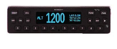
52 (iv) Radio altimeter Verify each radio altimeter system functions correctly while monitoring the effects of Stratus ESG. Each unit should self-test correctly and be free of continuous variation while parked on the ramp. (v) Engine indications & fuel flow (engines operating) Aircraft must be taken off ground power (if necessary). Start aircraft engines. Check to be certain that all engine indicators read appropriately. Check to be certain that all fuel flow indicators read appropriately Compass swing test After successful completion of the above EMI tests, evaluate the necessity of a swing test Flight test NOTE: The flight test shall not be performed until after the system functional ground test and EMI test is complete and passes. It is recommended that a flight test be conducted after installation to verify proper operation and installation of Stratus ESG. A compliance report can be obtained by ing 9-AWA-AFS-300- ADSB-AvionicsCheck@faa.gov with the aircraft information. This method is controlled by the FAA and may be subject to change. For additional information visit the FAA website: 6. Using Stratus ESG See the Stratus ESG Pilot s Guide ( ) for a full description of Stratus ESG s function. Figure 3: Stratus ESG front panel Page 37 of 47
53 6.1. Mode selection keys Use the mode selection keys to change the transponder mode. The table below describes each of these modes. Mode Key Description Off PWR Stratus ESG is powered off. Standby Altitude Ground On SBY ALT (none) ON Stratus ESG is powered on and does not send responses to any ATC interrogations. Stratus ESG is powered on and responds to all Mode A/C/S interrogations. Altitude is reported. Stratus ESG is powered on and in ALT or On mode, but does not report altitude. Ground mode is automatically detected. Press the ALT or ON key to override Ground mode. Press SBY to remove this override. Stratus ESG is powered on and responds to all Mode A/C/S interrogations, but altitude reporting is suppressed. Table 25: Mode selection keys 6.2. Event indicators When certain events occur, an indicator will appear on your Stratus ESG display. The table below describes each indicator s meaning. Indicator Meaning 6.3. FUNC key ADS-B transmission contains GPS position information with a radius of containment under 1 nautical mile. A response was transmitted from a mode A/C/S interrogation. The indicator will time out if another reply does not occur within one second. A built-in-test (BIT) has failed. See Section of this document and the Stratus ESG Pilot s Guide for more information about BIT failures. Table 26: Event indicators Press the FUNC key or the arrow keys, to switch from the Default screen to the Pressure Altitude screen, GPS screen, Flight ID screen, and Brightness screen. These screens are described below: Pressure Altitude screen: Displays the current pressure altitude. If no valid altitude is detected or Stratus ESG is in On mode, the altitude field will be replaced by dashes. Page 38 of 47


54 Figure 4: Pressure Altitude screen GPS screen: Displays the aircraft s GPS position in degrees latitude and longitude. If no GPS signal is being received, the latitude and longitude fields will be replaced by dashes. Figure 5: GPS screen Flight ID screen: Displays the currently entered Flight ID. Figure 6: Flight ID screen Brightness screen: Allows for adjustment of screen brightness while in flight. Press ENT, then the left or right arrow keys to adjust brightness. Press ENT again to confirm the new setting Other keys Arrow keys Figure 7: Brightness screen Use the arrow keys to advance forward and backward when entering numbers or letters and to cycle through options in Configuration mode. They can also be used for cycling through the display screens. Numerical keys Use the numerical keys to enter information such as the flight ID or squawk code. See Section 6.5 for directions for how to enter the squawk code for your aircraft s flight, and see Section 6.6 for instructions on how to enter a flight ID. Sometimes, a textual or non-numerical input will be required. If this is the case, press the number that is associated with the letter group you want to input, according to the graphic on the screen. To cycle through the letters associated with each number, press the number key Page 39 of 47
55 repeatedly until the letter you want to input appears. You can input a space after cycling through all of the letters for a particular number key. Once the correct character is selected, use the arrow keys to advance to the next field to enter the next character in the sequence. Identification (IDENT) key If you are instructed by Air Traffic Control (ATC) to IDENT, press the IDENT key on your Stratus ESG. Pressing IDENT will make your aircraft s reply pulse on ATC s monitors for 18 seconds. IDENT will be shown on the display while IDENT is activated. VFR key Press the VFR key to broadcast the VFR squawk code. The factory-set VFR code is 1200, but the default number may be reconfigured. Power (PWR) key The PWR key is used to power Stratus ESG on and off. When Stratus ESG is powered on, it retains the last used squawk code and operation mode Entering a squawk code While on any screen that the squawk code is shown, press the appropriate number keys (0 through 7) to enter the squawk code. The new digits will be shown on the display screen. Five seconds after the fourth digit is entered, Stratus ESG will automatically save the entered squawk code. NOTE: If you incorrectly enter a number before the code is automatically saved, press the left arrow key and then press the correct number key. WARNING: Squawk codes 7500 (hijacking), 7600 (radio failure), and 7700 (emergency) are reserved for emergencies. There may also be other reserved codes, depending on the region the pilot is flying in. It is the pilot in command s responsibility to comply with their jurisdiction's operating rules and regulations Entering the flight identification number To enter your flight identification number: 1. Press FUNC or the arrow keys until Flight ID appears. The registration number will be displayed in the Flight ID screen. 2. Press ENT. 3. Use the number keys to overwrite the registration number. Use the left and right arrow keys to change the cursor position. See Section for instructions on how to enter non-numerical input. Page 40 of 47

56 NOTE: If the new flight ID is less than 8 digits and there are characters from the registration number remaining after the new flight ID has been entered, insert spaces in those fields to overwrite the characters. 4. Press ENT to confirm the new flight ID. Figure 8: Flight ID entry screen Page 41 of 47
57 7. Troubleshooting The following table addresses problems that could arise while using Stratus ESG and presents troubleshooting steps that could correct the problem. Problem GPS information is not being received Troubleshooting Steps 1. Verify that the aircraft has a clear view of the sky. 2. Verify that the antenna connections and cables are not loose. 3. Verify that the coax cable is connected to the correct port. NOTE: Initial GPS fix could take up to 20 minutes. GPS signal quality is reduced 1. Turn off all avionics. 2. Enter into configuration mode on Stratus ESG. 3. Go to the CN0 diagnostic screen and wait for the CN0 values to populate. 4. Turn on one avionic at a time. If the CN0 values drop by 2 db or more, there might be an interference problem. The avionic causing the interference might need to be relocated in the cockpit, antennas might need to be moved farther apart, or filters might need to be added to the avionic. Transponder is not receiving the squat switch position The power key does not power on Stratus ESG 1. Check the connections and the pin-out of the transponder to verify that the squat switch port is correctly connected. 2. Verify that the squat switch works independent of the transponder. 1. Verify that the power key is not stuck. 2. Verify that the circuit breaker has not tripped. If it has tripped: Reset the circuit breaker switch and try the power key again. NOTE: If the circuit breaker opens it may be reset only once. If it did not trip: Verify that the electrical connection to the transponder is secure. Verify that the voltage at the input to the unit is between 11 VDC and 36 VDC. Page 42 of 47
58 The altitude displayed is incorrect 1. Enter into configuration mode on Stratus ESG and verify that the altitude source is set as the currently used altitude source. If the altitude source is a serial connection, verify that the correct encoding option was selected. 2. Verify that the correct connections are made to the transponder. 3. Use an altitude simulator to verify the cabling. 4. Verify that there is not a problem with the altitude source. The screen displays a Built in Test (BIT) failure The display screen will display a warning message and a degraded state indicator if any of Stratus ESG s BITs fail. The Stratus ESG screen might display a warning message with the instructions below. Below is guidance regarding how to assess the failure: PRESS FUNC TO CLEAR: A non-critical error has been detected. The transponder will run in a degraded state until the error is resolved. Contact Appareo for further assistance. PLEASE RESTART UNIT: A critical error has been detected. Restarting the unit may fix the error. If the message returns after restarting, contact Appareo for further assistance. PLEASE SHUTDOWN UNIT: A critical error has been detected. Power off the unit and do not turn it back on. Contact Appareo for further assistance. OVERHEATED: The transponder has overheated. Transponder function will resume when the transponder cools down. WAITING TO BE UNSTUCK: A key has been depressed for more than 20 seconds. If a key is stuck, try to unstick the key. WAITING FOR RELEASE: The external suppression input is constantly in a suppressed state. Contact Appareo for further assistance. ATTEMPTING TO RECOVER: A squitter rate error has been detected. The transponder may recover itself, but if it does not, restart the unit. If the message returns after restarting, contact Appareo for further assistance. Page 43 of 47
59 Technical Assistance For support, please contact Appareo at By mail: 1830 NDSU Research Circle North Fargo, ND United States of America Page 44 of 47
60 Nomenclature: Stratus ESG Transponder Part number: Appendix A TSO number: TSO-C112e, TSO-C145d, TSO-C166b Manufacturer s specification and/or other applicable specification: Manufacturer: Appareo Systems Address: 1830 NDSU Research Circle North, Fargo, ND 58102, USA Conditions DO-160G Section Description of tests conducted Temperature and Altitude 4.0 Low Temperature Equipment tested to Category B1. High Temperature Equipment tested to Category B1. Operating High Temp Test Equipment tested to Category B1. In-Flight Loss of Cooling Equipment identified as Category X, no test performed. Altitude Equipment tested to Category B1. Decompression Overpressure Equipment identified as Category X, no test performed. Equipment identified as Category X, no test performed. Temperature Variation 5.0 Equipment tested to Category C. Humidity 6.0 Equipment tested to Category A. Operational Shocks and Crash Safety 7.0 Operational Shocks 7.2 Equipment tested to Category B. Crash Safety 7.3 Equipment tested to Category B. Aircraft type: 5F Page 45 of 47
61 8.0 Vibration Equipment tested to Category S Group 3 during, 1 after Explosion Proofness 9.0 Equipment identified as Category X, no test performed. Waterproofness 10.0 Equipment identified as Category X, no test performed. Fluids Susceptibility 11.0 Equipment identified as Category X, no test performed. Sand and Dust 12.0 Equipment identified as Category X, no test performed. Fungus Resistance Test 13.0 Equipment identified as Category X, no test performed. Salt Fog Test 14.0 Equipment identified as Category X, no test performed. Magnetic Effect 15.0 Equipment tested to Category A. Power Input 16.0 Normal Operating Conditions Equipment tested to Category BXX. Group 3 during, 2 after Voltage Equipment tested to Category BXX. Abnormal Operating Conditions Equipment tested to Category BXX. Group 3 during, 2 after Voltage Spike 17.0 Equipment tested to Category A. Audio Frequency Conducted Susceptibility 18.0 Equipment tested to Category B. Induced Signal Susceptibility 19.0 Equipment tested to Category ZCX. Radio Frequency Susceptibility 20.0 Conducted Susceptibility 20.4 Equipment tested to Category TT. Radiated Susceptibility 20.5 Equipment tested to Category TT. Emission of Radio Frequency Energy Lightning Induced transient Susceptibility Lightning Direct Effects Equipment tested to Category B Equipment tested to Category A1XXXX. Equipment identified as Category X, no test performed. Page 46 of 47
62 Icing 24.0 Electrostatic Discharge 25.0 Equipment identified as Category X, no test performed. Equipment tested to Category A. No group test during, 2 after Fire, Flammability 26.0 Flammability testing was performed utilizing the method as indicated in 14 CFR Part 25 Appendix F. Table 27: DO-160G tests performed Page 47 of 47
63


64 ADS-B IN READY FOR TAKEOFF Subscription-Free Weather ADS-B Traffic Backup Attitude (AHRS) $899


65 THE BEST ADS-B RECEIVER IS BETTER THAN EVER Stratus is the simple-to-use, pocket-sized, portable wireless receiver that transforms your ipad into the ultimate flight tool. Get subscription-free weather, GPS information, backup attitude and ADS-B traffic all integrated with ForeFlight Mobile. Easy situational awareness for an unbelievable price. FREE IN-FLIGHT WEATHER Get NEXRAD radar, METARs, TAFs, TFRs, AIRMETs, SIGMETs, NOTAMs and more on your ipad with no subscription fees ever. Stratus Replay allows you to turn off the ipad screen and save battery; when you turn the screen on again, Stratus will automatically send all the weather information you missed. AUTOMATIC FLIGHT DATA RECORDER Stratus is the first ADS-B receiver to offer a complete flight data recorder system. When this is enabled, Stratus automatically records your flight complete with GPS position, altitude speed and attitude. Flight logs are saved in ForeFlight, and can be viewed online, in Google Earth or in the CloudAhoy app. Ideal for proficiency flights and CFIs. STUNNING SYNTHETIC VISION DISPLAY With luminous terrain, night sky view, and a brilliant obstacle awareness system, ForeFlight with Synthetic Vision will forever change the way you fly. The builtin AHRS in Stratus 2S drives a super responsive pitch and bank instrument in the center of the Synthetic Vision view. In an emergency situation, you ve got a backup glass cockpit on your ipad. DUAL BAND ADS-B TRAFFIC Stratus 2S includes a dual band (978 MHz and 1090 MHz) receiver so it can display traffic information right on the ForeFlight Maps page. See relative altitude, climb/descent rate and projected track. Note: ADS-B traffic is limited unless your aircraft has ADS-B Out installed in the panel. STRATUS 2S FEATURES Subscription-Free Weather P WAAS GPS P ADS-B Traffic Dual Band Backup Attitude (AHRS) P Flight Data Recorder P Pressure Altitude Sensor P Battery Life 8 Hours* Connector USB Type C Suction Cup Window Mount P Price $899 BUY NOW at appareo.com/stratus *When using the optional interface cable kit, Stratus 2S is powered from the transponder.


66 CONNECT WITH THE STRATUS TRANSPONDER TO GET THE ULTIMATE ADS-B EXPERIENCE GPS Antenna ADS-B Antenna Optional Interface Cable Kit Using the optional interface cable kit, plug a Stratus receiver into the Stratus ESG connector plate to utilize aircraft power and externally mounted antennas. ADS-B OUT COMPLIANCE IN ONE BOX 1090 ES Transponder Built-In WAAS GPS GPS Antenna Included $2,995

67 DESIGNED, TESTED AND BUILT IN THE USA Stratus products are engineered, tested and manufactured in the United States, giving pilots the most reliable ADS-B products on the market NDSU Research Circle N Fargo, ND APPAREO.COM/STRATUS
68


69 Stratus 2i Installation Guide Revision 1.2
70 Stratus 2i Installation Guide Revision 1.2 Last Revised: October 12, 2016 Stratus 2i Installation Guide 2016 Appareo Systems, LLC. All Rights Reserved. Stratus 2i Installation Guide. All content within is copyrighted by Appareo Systems, LLC, and may not be reprinted without permission. The content of this guide is furnished for informational use only, is subject to change without notice, and should not be construed as a commitment by Appareo Systems, LLC. Appareo assumes no responsibility or liability for any errors or inaccuracies that may appear in the information content contained in this guide. Unauthorized replication of this guide is prohibited. Appareo, Appareo Systems, Stratus, and the Appareo logos are either registered trademarks or trademarks of Appareo Systems, LLC. MITRE is a registered trademark of the MITRE Corporation. ipad, iphone, and ipod touch are registered trademarks of Apple Inc. App Store is a service mark of Apple Inc. All other trademarks and registered trademarks are the sole property of their respective owners. Appareo Systems, LLC, 1810 NDSU Research Circle North, Fargo, ND USA. Record of Revision Revision Number Change Description Revision Date Inserted By 1.0 Initial release 05/20/16 CJW 1.1 CM /17/16 AAL 1.2 Added BNC jack to blind mate adapter to parts list and Section 3 install instructions 10/12/16 AAL Page 2 of 6
71 Stratus 2i Installation Guide Revision 1.2 Last Revised: October 12, Preparing for install This document is intended to help you determine the best method for installing Stratus 2i interface cables in an aircraft and connecting them to a Stratus ESG. NOTE: For instructions for how to install Stratus ESG, refer to the documentation provided with the transponder or in the Stratus ESG Dealer Portal. Supplied components: Stratus 2i ADS-B In portable receiver Cradle Stratus 2i Pilot s Guide Power serial interface cable RF interface cable 9-pin D-Sub connector with mounting hardware BNC jack to blind mate adapter 2. Placing Stratus 2i in the aircraft Choose an installation location that provides for the best line-of-sight between the Stratus 2i and the ipad for optimal Wi-Fi communication. It is important for Stratus 2i to be installed in the orientation indicated by the Direction of Flight arrow on the receiver. Stratus 2i can be placed upside down or sideways, as long as the Direction of Flight arrow points in the correct direction. The provided cradle is an optional accessory to help secure Stratus 2i during flight. Mounting methods and locations can be determined by the installer or pilot. NOTE: The mounting holes in the Stratus 2i cradle are compatible with many RAM mounts. Page 3 of 6
72 Stratus 2i Installation Guide Revision 1.2 Last Revised: October 12, Installing the interface cables NOTE: For instructions on installing Stratus ESG, reference the Stratus ESG Installation Instructions (Appareo document number for TSO installations and for STC installations). These documents can be found on the Stratus ESG Dealer Portal. 1. Wire the 9 pin D-Sub connector to the transponder following the wiring diagram on Page 5, allowing for a maximum harness length of 3 feet. Use 20 gauge wire for this harness. 2. Mate this 9-pin D-Sub connector with the Stratus 2i power serial interface cable and secure using the thumb screws. 3. Attach the BNC blind mate adapter to the ADSB AUX hole on the transponder backplate. 4. Attach the BNC connector of the Stratus 2i RF interface cable to Stratus ESG s ADSB AUX port. 5. Connect the remaining end of the power serial cable into the power port of Stratus 2i (marked by the power symbol). 6. Connect the remaining end of the Stratus 2i RF interface cable into the ADS-B port of Stratus 2i. Secure cables as necessary. 7. Power on the aircraft to ensure that Stratus 2i is receiving power. Refer to the LED indicator statuses on Page Configuring the transponder The transponder must be configured to allow for ADS-B In receiver information from the cockpit after Stratus 2i has been placed in the aircraft. 1. Enter into configuration mode on the transponder (while holding the FUNC key, press and release the PWR key). 2. Press FUNC or the arrow keys to navigate to the ADS-B Capability screen and press ENT. 3. Use the arrow keys to set the capability to UAT and 1090 ES (the frequencies Stratus 2i is capable of). 4. Press ENT. 5. Powering receiver on and off Once it is receiving aircraft power, Stratus 2i will automatically turn on. All LED indicators will briefly illuminate red and then green as the receiver powers on and auto-calibrates. If Stratus 2i is moved after being turned on, it must be re-calibrated in ForeFlight Mobile. Page 4 of 6
73 Stratus 2i Installation Guide Revision 1.2 Last Revised: October 12, Stratus ESG to Stratus 2i Wiring Diagram STRATUS ESG 37-DSUB 9-DSUB P1001 AIRCRAFT POWER 1 2 AIRCRAFT POWER 2 21 AIRCRAFT GROUND 1 1 AIRCRAFT GROUND V LIGHTING BUS HI 15 14V LIGHTING BUS HI 33 EXTERNAL STANDBY 7 5A VDC AIRCRAFT POWER TO LIGHT DIMMING BUS TRANSPONDER 2 PIN DESCRIPTION PIN 19 SWITCHED POWER OUTPUT 1 36 D D RS232-TX AUX 6 6 RS232-TX GPS 1PPS 7 18 AUX GROUND EXTERNAL SUPPRESS IN EXTERNAL SUPPRESS I/ DME MUTUAL SUPPRESSION (ARINC 709) EXTERNAL IDENT EXTERNAL SQUAT SWITCH WoW IDENT INPUT Optional ALTITUDE A1 ALTITUDE A4 ALTITUDE B2 ALTITUDE C1 ALTITUDE C4 ALTITUDE D4 ALTITUDE A2 ALTITUDE B1 ALTITUDE B4 ALTITUDE C PARALLEL ALTITUDE ENCODER 9- DSUB AUX +5V POWER AUX +5V POWER AUX +5V POWER RS232-TX AUX RS232-TX GPS 1PPS AUX GROUND ALTITUDE COMMON (GND) 37 ALTITUDE COMMON (GND) P1002 XPNDR ANTENNA RF (BNC) XPNDR ANTENNA P1003 GPS ANTENNA IN RF (TNC) GPS ANTENNA P1004 ADS-B AUX RF (BNC) ADS-B AUX Guide: Black outline = applicable to Stratus 2i installation Page 5 of 6
74 Stratus 2i Installation Guide Revision 1.2 Last Revised: October 12, LED indicator status Label Color Condition Indicated GPS Signal Green 3-D Lock Off Receiver is powered off. Power Green (pulsing) Receiver is powered on and operational. (indicated by No power is being received; receiver is Off power symbol) powered off. Green ADS-B FIS-B signal has been received from multiple towers in the past three seconds. ADS-B Signal Yellow ADS-B FIS-B signal has been received from one tower in the past three seconds. Off ADS-B FIS-B signal has not been received in the past three seconds. Briefly red and then green Receiver is powering on and calibrating. Red (flashing) Built-in-test failure. Contact support for assistance. Yellow (flashing) Installing firmware update. All indicators Yellow (solid) Applying firmware update. Green for two seconds Firmware update complete. Off for five seconds, then flashing green Power button is depressed. After 30 seconds, factory reset process will begin. Green to yellow to green Factory reset process is complete Appareo Systems, LLC. All Rights Reserved. Page 6 of 6
75
76
77

78 1810 NDSU Research Circle North Fargo, ND July 14, 2016 Subject: STC permission to use FAA STC SA04112CH for Appareo Stratus ESG system Consistent with FAA Order C and AC21-40A, Appareo System, LLC, grants permission to Appareo Systems dealers, installers, and owners of the Stratus ESG units to utilize FAA STC SA04112CH and associated data, for sole and express purpose of installation and approval of the Appareo Systems Stratus ESG, and associated interfaces to previously approved equipment. Appareo Systems grants permission to use the associated data for obtaining other FAA approved means of installation for aircraft not covered in STC SA04112CH. Vernon J. Miller Jr. Sr. Certification Specialist Appareo Systems, LLC
STRATUS ES/ESG PILOT S GUIDE
 STRATUS ES/ESG PILOT S GUIDE COPYRIGHT INFORMATION 2015-2017 Appareo Systems, LLC. All rights reserved. Stratus ES/ESG Pilot s Guide. All content within is copyrighted by Appareo Systems, LLC, and may
Stratus 2i Installation Guide. Revision 2.0
 Stratus 2i Installation Guide Stratus 2i Installation Guide 201-17 Appareo Systems, LLC. All Rights Reserved. Stratus 2i Installation Guide. All content within is copyrighted by Appareo Systems, LLC, and
GTX 320A. Mode A/C Transponder. pilot s guide
 GTX 320A Mode A/C Transponder pilot s guide 2000 GARMIN Corporation GARMIN International, Inc. 1200 East 151 st Street, Olathe, Kansas 66062, U.S.A. Tel. 913/397.8200 or 800/800.1020 Fax 913/397.8282 GARMIN
Copyright Information
 PILOT S GUIDE Copyright Information Stratus 3 Pilot s Guide, 2018 Appareo Systems, LLC. All Rights Reserved. All content within is copyrighted by Appareo Systems, LLC and may not be reprinted without permission.
KGX 150/130 ADS -B Certified Transceivers & Receivers
 BendixKing By Honeywell 9201 -B San Mateo Blvd. NE Albuquerque, NM 87113 U.S.A. CAGE: 6PC31 Telephone: 1-505 -903-6148 Telephone: 1-855 -250-7027 (Toll Free in U.S.A.) Web site: http://www.bendixking.com
AIS 300 Installation Instructions
 Use these instructions to install the Garmin AIS 300 Automatic Identification System (AIS) Class B receiver device. Compare the contents of this package with the packing list on the box. If any pieces
Pilot s Operating Handbook Supplement AS-21
 SECTION 9 Pilot s Operating Handbook Supplement Mode S Transponder GARMIN GTX 335 / GTX 345 This supplement is applicable and must be inserted into Section 9 of the POH when a GARMIN GTX 335 or GTX 345
978 UAT (ADS-B out) INSTALLATION AND PILOT S GUIDE. Rev 1.0
 INSTALLATION AND PILOT S GUIDE. Rev 1.0") 978 UAT (ADS-B out) INSTALLATION AND PILOT S GUIDE Rev 1.0 2 Revision table Date Revision Comments Section July 22,2017 1.0 First Revision Nov 14, 2017 1.1 Adjustments by Ricardo L 8.2.4 Nov 27, 2017 1.2
978 UAT (ADS-B out) INSTALLATION AND PILOT S GUIDE Rev 1.0 2 Revision table Date Revision Comments Section July 22,2017 1.0 First Revision Nov 14, 2017 1.1 Adjustments by Ricardo L 8.2.4 Nov 27, 2017 1.2
Ping20S User and Installation Guide
 Ping20S User and Installation Guide ECCN 7A994 Page 1 30 2017 uavionix Corporation. All rights reserved. uavionix Corporation 300 Pine Needle Lane Bigfork, MT 59911 http://www.uavionix.com support@uavionix.com
AT01 AIRPLANE FLIGHT MANUAL
 Table of Contents Supplement AVE12 1. Section 1 General AVE12 3 2. Section 2 Operating Limitations AVE12 3 3. Section 3 Emergency Procedures AVE12 3 4. Section 4 Normal Procedures AVE12 4 5. Section 5
Trans-Cal Industries, Inc.
 Trans-Cal Industries, Inc. Model ATS-350 Altitude Encoder Test Set Operation Manual Trans-Cal Industries. Inc. 16141 Cohasset Street Van Nuys, CA 91406-2908 (800) 423-2913*(818) 787-1221*(818) 787-8916FAX
RFTX-1 Installation Manual
 RFTX-1 Installation Manual complete control Universal Remote Control RFTX-1 Installation Manual 2009-2014 Universal Remote Control, Inc. The information in this Owner s Manual is copyright protected. No
TN72 TABS GPS Receiver Installation Manual
 TN72 TABS GPS Receiver Installation Manual 01691-00-AC 16 February 2017 Trig Avionics Limited Heriot Watt Research Park Riccarton, Edinburgh EH14 4AP Scotland, UK Copyright Trig Avionics Limited, 2016
o-ring grease can be used to hold the o-ring in the groove during installation.
 42G1215A-XT-1-2 and 42G1215A-XT-1-3 ANTENNA GUIDE OM-20000154 Rev 1 December 2013 The 42G1215A-XT-1-3 and 42G1215A-XT-1-2 are active antennas designed to operate at the GPS L1 and L2 frequencies, 1575.42
AP 100 AUDIO PANEL. Installation and Operator s Manual
 VAL AVIONICS LTD AP 100 AUDIO PANEL Audio Management System Installation and Operator s Manual Revision 1 January 2007 P/N 1720100-1 Table of Contents Pg 1 SECTION I - GENERAL INFORMATION... 1 1.1 INTRODUCTION...
MANUFACTURER S DATA SECTION ROTORCRAFT FLIGHT MANUAL SUPPLEMENT
 MANUFACTURER S DATA SECTION OF ROTORCRAFT FLIGHT MANUAL SUPPLEMENT TO THE SIKORSKY S-76A ROTORCRAFT FLIGHT MANUAL Aircraft Serial Number: Aircraft Registration Number: This supplement must be attached
Field Hub Installation Guide. P/N Rev. C 05/15
 Field Hub Installation Guide P/N016-0171-380 Rev. C 05/15 E21714 Copyright 2015 Disclaimer While every effort has been made to ensure the accuracy of this document, Raven Industries assumes no responsibility
AWOS Net User s Manual
 Automated Weather Observing System AWOS Net User s Manual 3211-001 Rev. A All Weather Inc. 1165 National Drive Sacramento, CA 95834 USA 800.824.5873 www.allweatherinc.com Copyright 2011 2018, All Weather,
Microair Avionics Pty Ltd Airport Drive Bundaberg Queensland 4670 Australia Tel: Fax:
 Microair Avionics Pty Ltd Airport Drive Bundaberg Queensland 4670 Australia Tel: +61 7 41 553048 Fax: +61 7 41 553049 e-mail: sales@microair.com.au About This Document This supplement describes the installation
Operating on the Radio Frequency of 1090 Megahertz (MHz)
") Deviation Request #107 for an ETSO approval for CS ETSO applicable to Extended Squitter Automatic Dependent Surveillance Broadcast (ADS B) and Traffic Information Service Broadcast (TIS B) Equipment Operating
Deviation Request #107 for an ETSO approval for CS ETSO applicable to Extended Squitter Automatic Dependent Surveillance Broadcast (ADS B) and Traffic Information Service Broadcast (TIS B) Equipment Operating
Broadband Step-Up Transformer. User Manual
 Broadband Step-Up Transformer User Manual 990-1930 09/2004 Introduction Introduction About this unit The APC Step-Up Transformer provides 220 V power from 60 VAC Broadband cable systems. Safety Electrical
TT31 Mode S Transponder Installation Manual
 TT31 Mode S Transponder Installation Manual 00455-00-AM 27 March 2012 Heriot Watt Research Park Riccarton, Currie EH14 4AP Scotland, UK Copyright, 2012 This page intentionally left blank CONTENTS 1. PREFACE...
AIRPLANE FLIGHT MANUAL AQUILA AT01. Date of Issue A.01 Initial Issue (minor change MB-AT ) all March
 all March") 0.1 LIST OF REVISIONS AND AMENDMENTS Revision Reason for Amendment/Revision Affected Pages Date of Issue A.01 Initial Issue (minor change MB-AT01-00297) all 2009 19. March 0.2 LIST OF EFFECTIVE PAGES Page
0.1 LIST OF REVISIONS AND AMENDMENTS Revision Reason for Amendment/Revision Affected Pages Date of Issue A.01 Initial Issue (minor change MB-AT01-00297) all 2009 19. March 0.2 LIST OF EFFECTIVE PAGES Page
SkyEcho Installation and Pilot s Guide
 SkyEcho Installation and Pilot s Guide ECCN 7A994 Page 1 20 2017 uavionix Corporation. All rights reserved. uavionix Corporation 380 Portage Ave. Palo Alto, CA 94306 http://www.uavionix.com support@uavionix.com
# Made In USA. Simple GPS Tracker Parts List
 Needed Tools and Materials Compatible Ebay (to mount electronics to) Drill and Screwdriver (for mounting Transmitter to ebay) Compatible Battery (for powering Airborne Transmitter) Optional Tools / Finishing
SIR-WRR1. User's Guide SIRIUS Echo Antenna. Signal Repeater System Accessory
 SIR-WRR1 User's Guide SIRIUS Echo Antenna Signal Repeater System Accessory Desktop SIRIUS Docking Echo Station Antenna FCC NOTICE: This device complies with part 15 of the FCC Rules and with RSS-210 of
TN72 TABS GPS Receiver Installation Manual
 TN72 TABS GPS Receiver Installation Manual 01691-00-AF 18 August 2017 Trig Avionics Limited Heriot Watt Research Park Riccarton, Edinburgh EH14 4AP Scotland, UK Copyright Trig Avionics Limited, 2016 This
MS-CEFB Filter Box. Installation Guide
 MS-CEFB Filter Box Magnum Energy, Inc. 2211 West Casino Rd. Everett, WA 98204 Phone: 425-353-8833 Fax: 425-353-8390 Web: http://magnumenergy.com Installation Guide Introduction Introduction The CE Filter
P/N:
 - Copyright 2009-2016 NavWorx Page 1 of 128 All rights reserved. Printed in the U.S.A. Business Address: NavWorx Incorporated 3706 Big A Road Rowlett, TX 75089 Telephone: (888)-NAVWORX (628-9679) Facsimile:
NSPL-500. AIS/VHF antenna splitter. User Manual ENGLISH.
 NSPL-500 AIS/VHF antenna splitter User Manual ENGLISH www.bandg.com www.simrad-yachting.com www.lowrance.com Preface As Navico is continuously improving this product, we retain the right to make changes
Keychain Radio Remote Control System
 Innovation in Mobility Keychain Radio Remote Control System Operator Manual 04/23/02 95-2002 RICON CORPORATION All Rights Reserved U.S. and foreign patents pending Printed in the United States of America
500S Smart Antenna Installation and Operation Manual. P/N Rev. A 09/17 E29808
 500S Smart Antenna Installation and Operation Manual P/N 016-0171-668 Rev. A 09/17 E29808 Copyright 2017 1 Disclaimer While every effort has been made to ensure the accuracy of this document, Raven Industries
Inline Antenna Signal Amplifier
 1500528 User s Guide Inline Antenna Signal Amplifier We hope you enjoy your In-Line Antenna Signal Amplifier from RadioShack. Please read this user s guide before using your new signal amplif ier. Package
Distribution Amplifiers 1
 Distribution Amplifiers 1-30dB PUT 49-750 MHz 43 db GA POWER DOUBLED P/N: 1002705 REVERSE GA M MAX DESCRIPTION The R.L. DRAKE models DA8642, DA8632,, and DA7533, are broadband distribution amplifiers designed
Microair Avionics Pty Ltd Airport Drive Bundaberg Queensland 4670 Australia Tel: Fax:
 Microair Avionics Pty Ltd Airport Drive Bundaberg Queensland 4670 Australia Tel: +61 7 41 553048 Fax: +61 7 41 553049 e-mail: sales@microair.com.au About This Document This supplement describes the installation
o-ring grease can be used to hold the o-ring in the groove during installation.
 42G1215A-XT-1 ANTENNA GUIDE OM-20000152 Rev 1 December 2013 The 42G1215A-XT-1 is an active antenna designed to operate at the GPS L1 and L2 frequencies, 1575.42 and 1227.60 MHz. The antenna is aircraft
GTX TM 330, GTX TM 330D TRANSPONDER INSTALLATION MANUAL
 GTX TM 330, GTX TM 330D TRANSPONDER INSTALLATION MANUAL GARMIN International, Inc. 1200 E. 151 st Street Olathe, KS 66062 USA 190-00207-02 Revision 1 March 2002 Copyright 2002 GARMIN Ltd. or its subsidiaries
Installation and Operation Manual MSI. Multi-Sensor Interface Hub. Interface Module for all Sensors Network and Wireless CAUTION
 Installation and Operation Manual MSI Multi-Sensor Interface Hub Interface Module for all Sensors Network and Wireless CAUTION This equipment complies with the limits for a Class B digital device, pursuant
VAN STORAGE SOLUTIONS FOR THE WAY YOU WORK
 WWW.WEATHERGUARD.COM VAN STORAGE SOLUTIONS FOR THE WAY YOU WORK Weather Guard / KNAACK 420 E. Terra Cotta Ave. Crystal Lake, IL 60014 USA 800-456-7865 (Toll Free) 800-334-2981 (Fax) Knaack.OrderEntry@wernerco,.com
PORTROD WALL MOUNTED HEIGHT ROD
 PORTROD WALL MOUNTED HEIGHT ROD USER INSTRUCTIONS P/N UMPORTROD Rev 1-052112 1 PORTROD Thank you for your purchase of this Health o meter Professional product. Please read this manual carefully, and keep
AUDIO MODE SELECTOR MODEL AMS-6000
 AUDIO MODE SELECTOR MODEL AMS-6000 Installation and Operating Instructions Til Document No. 03RE325 Rev. n/c Issue 4 August 2007 Technisonic Industries Limited 240 Traders Boulevard, Mississauga, Ontario
An advisory circular may also include technical information that is relevant to the standards or requirements.
 Advisory Circular AC91-24 Automatic Dependent Surveillance Broadcast (ADS-B) Systems Revision 0 24 July 2018 General Civil Aviation Authority advisory circulars contain guidance and information about standards,
EQUIPMENT INSTALLATION MANUAL. for the GDC62 RADIO ALTIMETER INTERFACE UNIT P/N
 EQUIPMENT INSTALLATION MANUAL for the GDC62 RADIO ALTIMETER INTERFACE UNIT P/N 1102-4000-01 DAC International 6702 McNeil Drive Austin, TX 78729 Copyright 2013, DAC International. All rights reserved.
Advisory Circular. U.S. Department of Transportation Federal Aviation Administration
 U.S. Department of Transportation Federal Aviation Administration Advisory Circular Subject: Airworthiness Approval of Automatic Date: 11/07/12 AC No: 20-165A Dependent Surveillance - Broadcast (ADS-B)
Radio Remote(s) (Installation Manual)
 (Installation Manual)") Radio Remote(s) (Installation Manual) 87 Progress Avenue, Tyngsboro, MA 01879, USA Phone (978) 649-4ECU Fax (978) 649-8363 http://www.qtiusa.com Trademarks, Version, Printing, and Copyright Trademarks
Radio Remote(s) (Installation Manual) 87 Progress Avenue, Tyngsboro, MA 01879, USA Phone (978) 649-4ECU Fax (978) 649-8363 http://www.qtiusa.com Trademarks, Version, Printing, and Copyright Trademarks
MODEL 3810/2 Line Impedance Stabilization Network
 EMC TEST SYSTEMS FEBRUARY 1996 REV C PN 399197 MODEL 3810/2 Line Impedance Stabilization Network OPERATION MANUAL USA P.O. Box 80589 Austin, Texas 78708-0589 2205 Kramer Lane, Austin, Texas 78758-4047
TSSP-1 (Stainless Steel Thermistor Probe) Manual Rev A
 Manual Rev A") TSSP-1 (Stainless Steel Thermistor Probe) Manual 57-6028 Rev A This page intentionally left blank. 2 2014 Dyacon, Inc Contents NOTICES...4 Copyright 2014 Dyacon, Inc...4 Manufacturer...4 Declarations...5
TSSP-1 (Stainless Steel Thermistor Probe) Manual 57-6028 Rev A This page intentionally left blank. 2 2014 Dyacon, Inc Contents NOTICES...4 Copyright 2014 Dyacon, Inc...4 Manufacturer...4 Declarations...5
# Made In USA. Simple GPS Tracker Parts List. Needed Tools and Materials
 Needed Tools and Materials #09245 Made In USA Compatible Ebay (to mount electronics to) Drill and Screwdriver (for mounting Transmitter to ebay) Compatible Battery (for powering Airborne Transmitter) Optional
Vi6208, Vi6216, Vi6232 Vi6308, Vi6316, Vi6332
 MODELs Vi6208, Vi6216, Vi6232 Vi6308, Vi6316, Vi6332 Automatic Video Compensation UTP Receiver Hubs User s Manual 7810 Trade Street, Suite 100 San Diego, CA 92121, U.S.A. Phone: (858) 484-5209 Fax: (858)
GTX 327 Transponder Installation Manual
 GTX 327 Transponder Installation Manual 190-00187-02 April, 2008 Revision N Copyright 2008 Garmin Ltd. or its subsidiaries All Rights Reserved Except as expressly provided herein, no part of this manual
supplied o-ring grease can be used to hold the o-ring in the groove during installation.
 42GOXX16A4-XT-1-1 ANTENNA GUIDE OM-20000158 Rev 1 December 2013 The 42G1215A-XT-1 is an active GPS antenna that receives the GPS L1 1575.42 MHz frequency, the GLONASS L1 1602 1626 MHz frequencies, the
HE100A (P/N: ) INSTALL GUIDE VERSION 1.5 DOCUMENT#
 INSTALL GUIDE VERSION 1.5 DOCUMENT#") HE100A (P/N: 300100) INSTALL GUIDE VERSION 1.5 DOCUMENT# 300104 COPYRIGHT 2018 Blue Sky Network, LLC All rights reserved. No part of this manual may be reproduced, stored or distributed without written
HE100A (P/N: 300100) INSTALL GUIDE VERSION 1.5 DOCUMENT# 300104 COPYRIGHT 2018 Blue Sky Network, LLC All rights reserved. No part of this manual may be reproduced, stored or distributed without written
ELECTROSURGICAL UNIT ANALYZER
 ELECTROSURGICAL UNIT ANALYZER ESU-2000A USER MANUAL BC BIOMEDICAL ESU-2000A TABLE OF CONTENTS WARNINGS, CAUTIONS, NOTICES... ii DESCRIPTION... 1 OVERVIEW... 2 OPERATING INSTRUCTIONS... 3 MANUAL REVISIONS...
INSTRUCTION MANUAL V-42R. Dual Band Collinear Gain Vertical for MHz and GENERAL DESCRIPTION
 308 Industrial Park Road, Starkville, MS 39759 USA Ph: (662) 323-9538 FAX: (662) 323-6551 V-42R Dual Band Collinear Gain Vertical for 144-148 MHz and 436-450 INSTRUCTION MANUAL GENERAL DESCRIPTION The
KRAMER ELECTRONICS LTD. USER MANUAL MODEL: 912 Power Amplifier. P/N: Rev 2
 KRAMER ELECTRONICS LTD. USER MANUAL MODEL: 912 Power Amplifier P/N: 2900-000684 Rev 2 Contents 1 Introduction 1 2 Getting Started 2 2.1 Achieving the Best Performance 2 3 Overview 3 3.1 Defining the 912
A-16D A-Net Distributor
 A-16D A-Net Distributor For use with the Personal Monitor Mixing System Information in this document is subject to change. All rights reserved. Copyright 2003 Aviom, Inc. Printed in USA Document Rev. 1.03
TT31 Mode S Transponder Installation Manual
 TT31 Mode S Transponder Installation Manual 00455-00-AP 18 June 2014 Heriot Watt Research Park Riccarton, Currie EH14 4AP Scotland, UK Copyright 2006-2014 This page intentionally left blank CONTENTS 1.
Line 6 L I M I T E D R E F URBISH E D (B-ST O C K) W A RR ANT Y
 W A RR ANT Y") Line 6 L I M I T E D W A RR A N T Y PO L I C Y PLEASE READ THIS DOCUMENT CAREFULLY. IT CONTAINS IMPORTANT INFORMATION ABOUT YOUR RIGHTS AND OBLIGATIONS, AS WELL AS LIMITATIONS AND EXCLUSIONS THAT MAY APPLY
Line 6 L I M I T E D W A RR A N T Y PO L I C Y PLEASE READ THIS DOCUMENT CAREFULLY. IT CONTAINS IMPORTANT INFORMATION ABOUT YOUR RIGHTS AND OBLIGATIONS, AS WELL AS LIMITATIONS AND EXCLUSIONS THAT MAY APPLY
Installation Instructions
 SYSTXBBSAM01 EVOLUTION SYSTEM ACCESS MODULE Installation Instructions NOTE: Read the entire instruction manual before starting the installation. pointsett U.S. Pat No. 7,415,102 Fig. 1 - Evolution System
BendixKing Buyer s Guide. CNI 5000 Integrated Avionics System ADS-B Out Upgrade (Rev 4.0 June 13, 2018)
") BendixKing Buyer s Guide 2018BK CNI 5000 ADS-B Out Upgrade CNI 5000 Integrated Avionics System ADS-B Out Upgrade (Rev 4.0 June 13, 2018) Joining CitationJet models 525 & 525A, BendixKing is pleased to
BendixKing Buyer s Guide 2018BK CNI 5000 ADS-B Out Upgrade CNI 5000 Integrated Avionics System ADS-B Out Upgrade (Rev 4.0 June 13, 2018) Joining CitationJet models 525 & 525A, BendixKing is pleased to
Copyright Teletronics International, Inc. Patent Pending
 Copyright 2003 By Teletronics International, Inc. Patent Pending FCC NOTICES Electronic Emission Notice: This device complies with Part 15 of the FCC rules. Operation is subject to the following two conditions:
Instruction Manual Model Upconverter
 Instruction Manual Model 2006-01 Upconverter October 2013, Rev. B IF IN RF OUT Data, drawings, and other material contained herein are proprietary to Cross Technologies, Inc., but may be reproduced or
Using the USB Output Port to Charge a Device
 Table of Contents ----------------------------------- 2 Features ----------------------------------------------- 3 Controls and Functions ---------------------------------- 4 ER210 Power Sources -----------------------------------
INSTALLATION MANUAL AND OPERATING INSTRUCTIONS
 INSTALLATION MANUAL AND OPERATING INSTRUCTIONS MD200-202/203/206/207 Series COURSE DEVIATION INDICATOR Mid-Continent Instruments and Avionics Manual Number 8017702 9400 E. 34 th Street N. Wichita, KS 67226
ER200 COMPACT EMERGENCY CRANK DIGITAL WEATHER ALERT RADIO OWNER S MANUAL
 ER200 COMPACT EMERGENCY CRANK DIGITAL WEATHER ALERT RADIO OWNER S MANUAL Table of Contents -------------------------------------- 2 Features ----------------------------------------------- 3 Controls and
Thank you for buying this AIS antenna splitter.
 Thank you for buying this AIS antenna splitter. This product has been engineered to offer you the highest level of performance and durability and we hope that it will provide many years of reliable service.
TT31 Mode S Transponder Installation Manual
 TT31 Mode S Transponder Installation Manual 00455-00-AH 19 December 2008 Heriot Watt Research Park Riccarton, Currie EH14 4AP Scotland, UK Copyright, 2008 This page intentionally left blank CONTENTS 1.
Quick Start Guide. ELPRO 905U-L-T Wireless I/O Transmitter Unit. man_905u-l-t_quickstart_v1-7.doc
 Quick Start Guide ELPRO 905U-L-T Wireless I/O Transmitter Unit man_905u-l-t_quickstart_v1-7.doc ELPRO 905U-L-T Wireless I/O Transmitter Unit Quick Start Guide About this document This document is the ELPRO
Installation & Operation Manual SAGA1-K Series Industrial Radio Remote Control
 Installation & Operation Manual SAGA1-K Series Industrial Radio Remote Control Gain Electronic Co. Ltd. Table Of Contents Safety Considerations ------------------------------------------------------------2
Guide. Installation. Wilson Electronics, Inc. In-Building Wireless Amplifi er. Contents:
 Amplifier Installation Guide In-Building Wireless Amplifi er Contents: Guarantee and Warranty 1 Antenna Options and Accessories 2 Before Getting Started / How It Works 3 Installation Overview 4 Installing
TT31 Mode S Transponder Installation Manual
 TT31 Mode S Transponder Installation Manual 00455-00-AR 28 August 2017 Heriot Watt Research Park Riccarton, Currie EH14 4AP Scotland, UK Copyright 2006-2017 This page intentionally left blank CONTENTS
In-VehicleMAXIMUMSIGNALUSER GUIDE. Wireless Dual Band Amplifier
 In-VehicleMAXIMUMSIGNALUSER GUIDE Wireless Dual Band Amplifier TM Contents Warnings...2 Package Contents...2 Quick Start Guide...4 Choosing a location for your device...4 Installing the Exterior Antenna...5
AMERITRON RCS-12 AUTOMATIC ANTENNA SWITCH
 AMERITRON RCS-12 AUTOMATIC ANTENNA SWITCH INSTRUCTION MANUAL PLEASE READ THIS MANUAL BEFORE OPERATING THIS EQUIPMENT! 116 Willow Road Starkville, MS 39759 USA 662-323-8211 Version 3B Printed in U.S.A.
INSTALLATION MANUAL AND OPERATING INSTRUCTIONS
 INSTALLATION MANUAL AND OPERATING INSTRUCTIONS MD200-302/303/306/307 Series COURSE DEVIATION INDICATOR MID-CONTINENT INST. CO., INC MANUAL NUMBER 8017972 Revisions Rev. Date Description of Change ECO#
PTT- Z or PTT-U PUSH-TO-TALK Specification
 Federal Communication Commission Interference Statement This equipment has been tested and found to comply with the limits for a Class B digital device, pursuant to Part 15 of the FCC Rules. These limits
WEL-200 O P E R A T I N G I N S T R U C T I O N S W I R E L E S S E D G E L I N K
 O P E R A T I N G I N S T R U C T I O N S WEL-200 TM W I R E L E S S E D G E L I N K 4564 Johnston Parkway, Cleveland, Ohio 44128 P. 800 426 9912 F. 216 518 9884 Sales Inquiries: salessupport@emxinc.com
Guide. Installation. Wilson Electronics, Inc. Direct Connection High Power iden Amplifi er 800 MHz Band. Contents:
 Amplifier Installation Guide Direct Connection High Power iden Amplifi er 800 MHz Band Contents: Guarantee and Warranty 1 Before Getting Started / How it Works 3 Installing a Wilson Outside Antenna - In-Vehicle
GTX 328 Transponder Installation Manual
 GTX 328 Transponder Installation Manual 190-00420-04 March, 2007 Revision C Copyright 2007 Garmin Ltd. or its subsidiaries All Rights Reserved Except as expressly provided herein, no part of this manual
Glass Electrode Meter
 Glass Electrode Meter INSTRUCTION MANUAL FOR Glass Electrode R/C Meter MODEL 2700 Serial # Date PO Box 850 Carlsborg, WA 98324 U.S.A. 360-683-8300 800-426-1306 FAX: 360-683-3525 http://www.a-msystems.com
Ambient Weather F007TP 8-Channel Wireless Probe Thermometer User Manual
 Ambient Weather F007TP 8-Channel Wireless Probe Thermometer User Manual Table of Contents 1 Introduction... 2 2 Getting Started... 2 2.1 Parts List... 2 2.2 Probe Thermometer Sensor Set Up... 2 3 Remote
MATRIX 430. Entry level guidance Software version 1.03
 MATRIX 430 U S E R M A N U A L Entry level guidance Software version 1.03 GETTING STARTED 1. Power on the console. Setup machine 2. On guidance screen, press NAVIGATION AND GUIDANCE OPTIONS tab to display
DIGICELL ANYNET NETWORK ACCESS MODULE
 Comm Activity Network Status Service DigiCell Any NET Network Access Module Network Interface Network Service AMPS Cellemetry GSM SMS CDMA GPRS Ethernet 1xRTT RS-232 TCP/IP Input 1 Standard S3 off, S4
Ambient Weather F007TH Wireless Thermo-Hygrometer User Manual
 Ambient Weather F007TH Wireless Thermo-Hygrometer User Manual Table of Contents 1 Introduction... 2 2 Getting Started... 2 2.1 Parts List... 2 2.2 Thermo-Hygrometer Sensor Set Up... 2 3 Remote Sensor Installation...
USER MANUAL MODEL Parallel to Serial/ Serial to Parallel Interface Converter
 USER MANUAL MODEL 2029 Parallel to Serial/ Serial to Parallel Interface Converter C E R T I F I E D An ISO-9001 Certified Company Part #07M2029-B, Rev. C Doc. #102011UB Revised 6/16/09 SALES OFFICE (301)
User Manual January Opticom Infrared System RC790 Remote Coding Unit
 User Manual January 2010 Opticom Infrared System RC790 Remote Coding Unit 1. Description The Opticom Infrared System RC790 Remote Coding Unit is used to remotely program Model 794 series LED emitters.
Safe-Fly 2020 ADS-B Compliant GPS Module with Serial Data Combiner/Expander
 Safe-Fly 2020 ADS-B Compliant GPS Module with Serial Data Combiner/Expander Revision K 10/27/2017 GRTAvionics.com 1 Table of Contents Revision History...3 Description...4 Compatibility...4 Use with Non-Compatible
MPR kHz Reader
 MPR-5005 Page 1 Doc# 041326 MPR-5005 125kHz Reader Installation & Operation Manual - 041326 MPR-5005 Page 2 Doc# 041326 COPYRIGHT ACKNOWLEDGEMENTS The contents of this document are the property of Applied
Opus 21 s80 Integrated Amplifier Owner's Manual
 Opus 21 s80 Integrated Amplifier Owner's Manual r e s o l u t i o n From all of us at Resolution Audio, thank you for choosing the Opus 21 s80 amplifier. We went to great lengths to design and produce
NCS-C150 INSTRUCTION MANUAL Rev A. Collcomm Inc. Shipping Address 2310 Pendley Road Cumming, Georgia 30041
 NCS-C150 INSTRUCTION MANUAL Rev A Collcomm Inc. d.b.a. NCS Shipping Address 2310 Pendley Road Cumming, Georgia 30041 Mailing Address 1595 Peachtree Parkway Suite 204-123 Cumming, Georgia 30041 Toll Free
TT31 Mode S Transponder Installation Manual
 TT31 Mode S Transponder Installation Manual 00455-00-AI 25 March 2009 Heriot Watt Research Park Riccarton, Currie EH14 4AP Scotland, UK Copyright, 2009 This page intentionally left blank CONTENTS 1. PREFACE...
ATTENTION: PLEASE READ AND UNDERSTAND ALL INSTRUCTIONS AND WARNINGS BEFORE ASSEMBLING, INSTALLING OR USING THIS PRODUCT.
 PLAN YOUR VAN (TIPS FOR FASTER INSTALLATION) Installing your Transit bulkhead is very clear cut following these instructions. Before cutting or drilling in the floor, verify the location of you gas tank,
SureCross DX80 FlexPower EZ-LIGHT Node with Integrated Battery
 SureCross DX80 FlexPower EZ-LIGHT Node with Integrated Battery Node with an integrated battery for the EZ-LIGHT family 900 MHz, Internal battery model Features The SureCross DX80 is a radio frequency network
Ping200S User and Installation Guide
 Ping200S User and Installation Guide ECCN 7A994 Page 1 32 2017 uavionix Corporation. All rights reserved. uavionix Corporation 380 Portage Ave. Palo Alto, CA 94306 http://www.uavionix.com support@uavionix.com
X80 Activator. User's Manual. Version 1.1.
 X80 Activator User's Manual Version 1.1 www.buckeyecam.com Table of Contents 1. Warnings... 3 2. Overview... 4 3. Getting Started... 5 4. Using the Activate Button... 7 5. Wiring... 8 6. Specifications...
Ditch Witch 750 Tracker Specs Provided by FOREWORD
 750/752 Display - FOREWORD 1 Ditch Witch 750 Tracker Specs Provided by www.aaatesters.com FOREWORD This manual is an important part of your equipment. It provides safety information and operation instructions
JMAA-1800HR15. Installation and Operation Instructions. 180w Performance Series Amplifier Kit For Harley RoadGlide/ Ultra
 180w Performance Series Amplifier Kit For 2015-2018 Harley RoadGlide/ Ultra # JMAA-1800HR15 2017 J&M Corporation. All rights reserved. 9/17 Installation and Operation Instructions Product Description This
Model 1791 VHF Radio User's Manual
 Model 79 VHF Radio User's Manual ALL WEATHER INC 65 NATIONAL DRIVE SACRAMENTO, CA 95834 WWW.ALWEATHERINC.COM 79 VHF RADIO USER'S MANUAL CONTENTS INTRODUCTION... Description... Transmitter Module... Power
GTS Traffic Systems. Pilot s Guide
 GTS Traffic Systems Pilot s Guide 2014 Garmin Ltd. or its subsidiaries. All rights reserved. Garmin International, Inc., 1200 East 151st Street, Olathe, KS 66062, U.S.A. Tel: 913/397.8200 Fax: 913/397.8282
Model 5100F. Advanced Test Equipment Rentals ATEC (2832) OWNER S MANUAL RF POWER AMPLIFIER
 OWNER S MANUAL RF POWER AMPLIFIER") Established 1981 Advanced Test Equipment Rentals www.atecorp.com 800-404-ATEC (2832) OWNER S MANUAL Model 5100F RF POWER AMPLIFIER 0.8 2.5 GHz, 25 Watts Ophir RF 5300 Beethoven Street Los Angeles, CA 90066
Established 1981 Advanced Test Equipment Rentals www.atecorp.com 800-404-ATEC (2832) OWNER S MANUAL Model 5100F RF POWER AMPLIFIER 0.8 2.5 GHz, 25 Watts Ophir RF 5300 Beethoven Street Los Angeles, CA 90066
Watcheye S AIS Splitter. manual
 Watcheye S AIS Splitter manual Thank you for buying this AIS antenna splitter. This product has been engineered to offer you the highest level of performance and durability and we hope that it will provide