AIRPLANE FLIGHT MANUAL AQUILA AT01. Date of Issue A.01 Initial Issue (minor change MB-AT ) all March
|
|
|
- Della Henry
- 6 years ago
- Views:
Transcription
1
2 0.1 LIST OF REVISIONS AND AMENDMENTS Revision Reason for Amendment/Revision Affected Pages Date of Issue A.01 Initial Issue (minor change MB-AT ) all March 0.2 LIST OF EFFECTIVE PAGES Page Revision Date Page Revision Date AVE22-1 to AVE20-9 A TABLE OF CONTENTS Section 1 GENERAL AVE22-3 Section 2 OPERATING LIMITATIONS AVE22-3 Section 3 EMERGENCY PROCEDURES AVE22-3 Section 4 NORMAL PROCEDURES AVE22-4 Section 5 PERFORMANCE AVE22-4 Section 6 WEIGHT AND BALANCE AVE22-4 Section 7 SYSTEMS DESCRIPTION AVE22-5 Section 8 HANDLING, SERVICE AND MAINTENANCE AVE22-9 FM-AT A AVE22-2
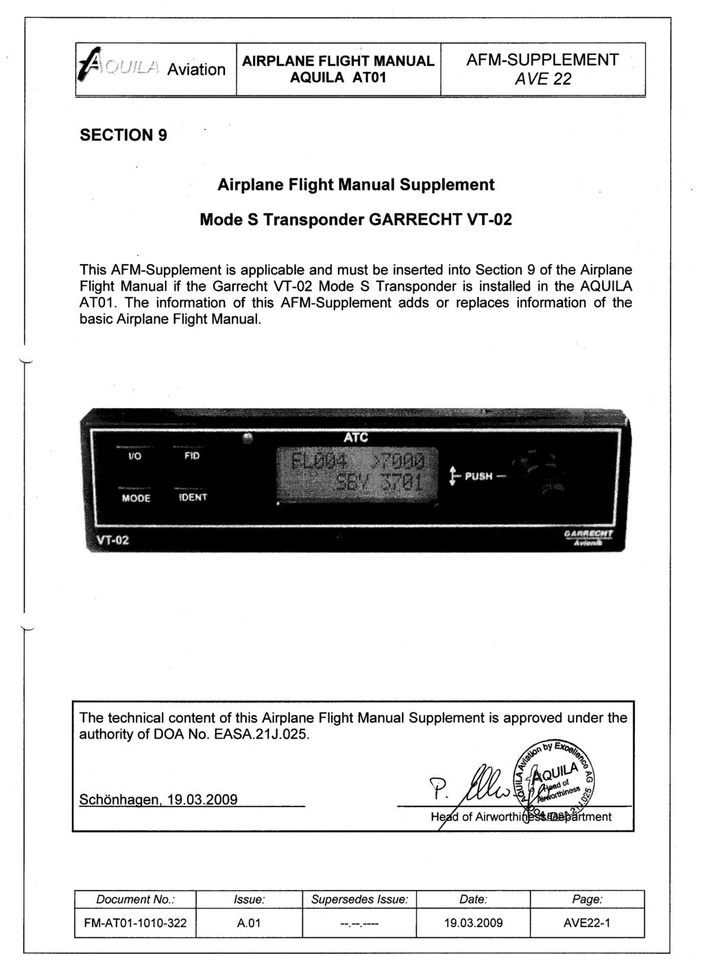
3 1. GENERAL This Supplement provides the information necessary for the efficient operation of the when the Mode S Transponder GARRECHT VT-02 is installed. It contains a general description of the Transponder, its basic operation and its integration into the. For a detailed description of the Mode S Transponder GARRECHT VT-02 and full operating instructions, refer to the effective issue of the VT-02 User Manual, E. The information contained within this Supplement is to be used in conjunction with the complete Airplane Flight Manual. Furthermore, the VT-02-User Manual should always be carried on board of the aircraft during flight. 2. OPERATING LIMITATIONS A connection of the VT-02 with a TCAS collision avoidance system is currently not intended for the. The operating limitations of the basic Airplane Flight Manual apply without any changes or restrictions. 3. EMERGENCY PROCEDURES TO TRANSMIT A SIGNAL REPRESENTING LOSS OF ALL COMMUNICATION (IN CONTROLLED AIRSPACE): Mode Key: Double shaft rotary encoder outer knob Inner knob of the double shaft rotary encoder TO TRANSMIT AN EMERGENCY SIGNAL: Mode Key: Double shaft rotary encoder outer knob Inner knob of the double shaft rotary encoder Press until Mode ALT active. Select 7600 operating code. Push, activate 7600 operating code. Press until Mode ALT active. Select 7700 operating code. Activate 7700 operating code. FM-AT A AVE22-3
4 4. NORMAL PROCEDURES NOTE The expected coverage of the VT-02 is limited to the line of sight. Low altitude or aircraft antenna shielding by the aircraft itself may result in reduced range. Range can be improved by climbing to a higher altitude BEFORE TAXIING 1. Avionic Master Switch ON The transponder will switch into the standby (SBY) mode. The transponder is activated but will not respond to any interrogations from the ATC Secondary Surveillance Radar BEFORE TAKE-OFF 1. Transponder Mode Selection Key ALT In this mode the transponder will respond in Mode A, Mode C and Mode S operation (identification and altitude) to interrogations from ATC and TCAS equipped aircrafts. NOTE Pressing the Mode Selection Key ON activates only Mode A-operation of the Transponder. The Transponder will respond to interrogations with the identification code only. The replies do not include altitude information AFTER LANDING 1. Transponder Mode Selection Key SBY 5. PERFORMANCE No change to the basic Airplane Flight Manual. 6. WEIGHT AND BALANCE The change of the empty weight and corresponding centre of gravity after the installation or removal of the Garrecht VT-02 Mode S Transponder has to be FM-AT A AVE22-4

5 determined and recorded in accordance with section 6 of the basic Airplane Flight Manual. 7. SYSTEMS DESCRIPTION GENERAL The Garrecht VT-02 panel mounted Non-Diversity Mode S Transponder is a radio transmitter and receiver that operates on radar frequencies, receiving ground radar or TCAS interrogations at 1030 MHz and transmitting a coded response of pulses to ground-based radar on a frequency of 1090 MHz. The VT-02 is equipped with IDENT capability that activates the Special Position Identification (SPI) pulse for 18 seconds. Mode S transmit/receive capability also requires 1090 MHz transmitting and 1030 MHz receiving for Mode S functions. In addition to displaying the selected transponder code, reply symbol and mode of operation, the VT-02 screen also displays pressure altitude. The VT-02 transponder is powered on by pressing the I/O key. After power on, a startup page will be displayed while the unit performs a self-test. To activate the Transponder, the ALT/BAT-Master Switch as well as the Avionics Master Switch has to be in the ON position. GARRECHT VT-02 FRONT VIEW TRANSPONDER MODE SELECTION KEYS Display: SBY Selects the standby mode. When in standby mode, the transponder will not reply to any interrogations. FM-AT A AVE22-5
6 ON ALT Selects MODE A operation of the transponder. In this mode, the transponder replies to interrogations, as indicated by the Reply Symbol ( R ). Replies do not include altitude information. Selects MODE A, MODE C and MODE S operation of the transponder. In ALT mode, the transponder replies to identification and altitude interrogations, as indicated by the Reply Symbol ( R ). Replies to altitude interrogations include the standard pressure altitude received from the internal altitude source (Altitude Encoder), which is not adjusted for barometric pressure. Any time the function ON or ALT is selected, the transponder becomes an active part of the Air Traffic Control Radar Beacon System (ATCRBS). The transponder also responds to interrogations from TCAS equipped airplanes. CODE SELECTION Code selection is done with the double shaft rotary encoder providing 4096 active identification codes. Rotating the outer knob of the double shaft encoder selects the position of the code to be modified. A blinking cursor is indicating the selected position. Use the inner knob to modify the value at the selected position. When all changes are done, press the inner button to activate the modified standby code. NOTE The identification code should be entered carefully, irrespective if assigned by ATC, or using a standard transponder code. Important Codes: VFR code for any altitude in the US (Refer to ICAO standards) VFR code commonly used in Europe (Refer to ICAO standards) VFR code commonly used in Europe (Refer to ICAO standards) Loss of communications Emergency FM-AT A AVE22-6
7 KEYS FOR OTHER VT-02 FUNCTIONS I/O IDENT FID To switch on the system, press key I/O shortly. After the start, the unit performs the built in test and shows the operating mode. For switching off, press key I/O for at least 3 seconds. Release the key, when the LCD becomes blank. IDENT key pressed activates the Special Position Identification (SPI) Pulse for 18 seconds, identifying your transponder return from others on the air traffic controller s screen. The word IDENT will appear in the upper left corner of the display while the IDENT mode is active. Pressing the flight ID key invokes the menu to setup the flight ID. The Flight ID is transmitted with every Mode-S interrogation. NOTE VFR- Function The flight id may be changed if required. Usually the FID is the callsign of your aircraft unless field 7 of the flight plan contains other data. Before each flight check always your flight-id has been set correctly. To simplify operation, the VT-02 provides a pre-programmable VFR code, which can be invoked by pressing the inner knob of the rotary encoder longer than 2sec. The previous active reply code will then be moved to the bottom line (inactive area) and overwrites the existing active value there. If the pre-programmed reply code is identical with the reply code in the bottom line, active and standby reply code will just be interchanged. FUNCTION DISPLAY In the upper left corner of the LCD screen the current pressure altitude (related to 1013,25 hpa) will be shown as Flight Level (FL). Replies are indicated by a blinking R in the lower left corner of the LCD screen. The current mode is shown in the centre of the bottom line of the screen. The current Transponder identification (Squawk) is indicated in the upper right corner of the LCD screen. The standby Transponder identification is indicated below. The activated mode will be shown centered in the lower row. FM-AT A AVE22-7
8 FAILURE ANNUNCIATION In case of failure, the system shows a W on the LCD screen. Additionally, a frequently repeated audio signal occurs. Both can be terminated by pressing the I/O key shortly. In case of detecting a fatal failure, the system will be switched into Standby (SBY) mode. All system operating will be terminated to prevent damages to system components. In this case, the system screen will show FAIL instead of active and standby reply code. No transponder data will be transfered. VT-02 MODE S TRANSPONDER FEATURES MODE S DATA TRANSMISSION In addition to 4096 codes and pressure altitude, the VT-02 is capable of transmitting airplane registration number or flight ID, transponder capability and maximum speed range. INTEGRATION INTO THE The electrical circuits of the Mode S Transponder Garrecht VT-02 are connected to the Avionic Bus of the on-board electrical power supply and protected by a 3 A circuit breaker which enables the complete disconnection of the Transponder unit from electric power. The circuit breaker is labelled with a placard denoted Transponder and is installed in the right section of the instrument panel among the other circuit breakers. Besides of the transponder unit, which is installed in the avionic rack in the midsection of the instrument panel, a transponder antenna and Altitude Encoder is part of the Transponder system. The Altitude Encoder is connected to the on-board Static Pressure System and is integrated in the VT-02-transponder. The transponder antenna is installed on the lower surface of the cockpit structure below the co-pilot s seat. For a detailed description of the integration of the Transponder unit into the aircraft and its connection to the on-board electrical system as well as its installation into the, refer to the effective revision of the Maintenance Manual of the AQUILA AT01, document no. MM-AT FM-AT A AVE22-8
9 8. HANDLING, SERVICE AND MAINTENANCE In order to increase the service life of the VT-02 Mode S Transponder, it should always be deactivated during engine start-up and shut-down since electrical surges during the start-up may cause damage to the unit. FM-AT A AVE22-9
Pilot s Operating Handbook Supplement AS-21
 SECTION 9 Pilot s Operating Handbook Supplement Mode S Transponder GARMIN GTX 335 / GTX 345 This supplement is applicable and must be inserted into Section 9 of the POH when a GARMIN GTX 335 or GTX 345
AT01 AIRPLANE FLIGHT MANUAL
 Table of Contents Supplement AVE12 1. Section 1 General AVE12 3 2. Section 2 Operating Limitations AVE12 3 3. Section 3 Emergency Procedures AVE12 3 4. Section 4 Normal Procedures AVE12 4 5. Section 5
MANUFACTURER S DATA SECTION ROTORCRAFT FLIGHT MANUAL SUPPLEMENT
 MANUFACTURER S DATA SECTION OF ROTORCRAFT FLIGHT MANUAL SUPPLEMENT TO THE SIKORSKY S-76A ROTORCRAFT FLIGHT MANUAL Aircraft Serial Number: Aircraft Registration Number: This supplement must be attached
RECORD OF REVISIONS. Revisions to this Supplement are recorded in the following table.
 Supplement D42L AFM RECORD OF REVISIONS Revisions to this Supplement are recorded in the following table. New or amended text will be indicated by a bold black vertical line in the left hand margin of
GTX 320A. Mode A/C Transponder. pilot s guide
 GTX 320A Mode A/C Transponder pilot s guide 2000 GARMIN Corporation GARMIN International, Inc. 1200 East 151 st Street, Olathe, Kansas 66062, U.S.A. Tel. 913/397.8200 or 800/800.1020 Fax 913/397.8282 GARMIN
Mode-S Transponder KTX2
 KTX2 Mode-S Transponder KTX-2-P/N 210-(XXXXX)-(XXX) Installation and User Manual - 1 - Revision List Revision Date Topic 1.0 20 Oct 2014 Initial Release 1.1 28 Oct.2014 Added SW 2.07 2.0 May 2015 New colour
Microair Avionics Pty Ltd Airport Drive Bundaberg Queensland 4670 Australia Tel: Fax:
 Microair Avionics Pty Ltd Airport Drive Bundaberg Queensland 4670 Australia Tel: +61 7 41 553048 Fax: +61 7 41 553049 e-mail: support@microair.com.au About This Document Microair Avionics have developed
Series III Avionics Pilot's Guide
 Chelton Avionics Inc. A Chelton Group Company 6400 Wilkinson Drive Prescott, AZ 86305 U.S.A. 150-041074 Rev. B i Wulfsberg Electronics Division, located in Prescott, Arizona, designs and manufactures the
10 Secondary Surveillance Radar
 10 Secondary Surveillance Radar As we have just noted, the primary radar element of the ATC Surveillance Radar System provides detection of suitable targets with good accuracy in bearing and range measurement
KMD 550/850. Traffic Avoidance Function (TCAS/TAS/TIS) Pilot s Guide Addendum. Multi-Function Display. For Software Version 01/13 or later
 Pilot s Guide Addendum. Multi-Function Display. For Software Version 01/13 or later") N B KMD 550/850 Multi-Function Display Traffic Avoidance Function (TCAS/TAS/TIS) Pilot s Guide Addendum For Software Version 01/13 or later Revision 3 Jun/2004 006-18238-0000 The information contained
N B KMD 550/850 Multi-Function Display Traffic Avoidance Function (TCAS/TAS/TIS) Pilot s Guide Addendum For Software Version 01/13 or later Revision 3 Jun/2004 006-18238-0000 The information contained
KGX 150/130 ADS -B Certified Transceivers & Receivers
 BendixKing By Honeywell 9201 -B San Mateo Blvd. NE Albuquerque, NM 87113 U.S.A. CAGE: 6PC31 Telephone: 1-505 -903-6148 Telephone: 1-855 -250-7027 (Toll Free in U.S.A.) Web site: http://www.bendixking.com
ADS-B Introduction Greg Dunstone
 ADS-B Introduction Greg Dunstone Surveillance Program Lead, Airservices Australia SURVEILLANCE Basics Primary and Secondary radar Why do we need Surveillance? Why surveillance? Improved safety Reduced
2. Radar receives and processes this request, and forwards it to Ground Datalink Processor (in our case named GRATIS)
") 1 Short Description The Traffic Information Service (TIS) provides information to the cockpit via data link that is similar to VFR radar traffic advisories normally received over voice radio. TIS is intended
1 Short Description The Traffic Information Service (TIS) provides information to the cockpit via data link that is similar to VFR radar traffic advisories normally received over voice radio. TIS is intended
Copyrighted Material - Taylor & Francis
 22 Traffic Alert and Collision Avoidance System II (TCAS II) Steve Henely Rockwell Collins 22. Introduction...22-22.2 Components...22-2 22.3 Surveillance...22-3 22. Protected Airspace...22-3 22. Collision
Mode S Skills 101. OK, so you ve got four basic surveillance skills, you ve got the: ATCRBS Skills Mode S Skills TCAS Skills ADS-B skills
 Mode S Skills 101 OK, so you ve got four basic surveillance skills, you ve got the: ATCRBS Skills Mode S Skills TCAS Skills ADS-B skills Fisher Fisher Slide 1 853D ELECTRONIC SYSTEMS GROUP MODE S 101 Prepared
STRATUS ES/ESG PILOT S GUIDE
 STRATUS ES/ESG PILOT S GUIDE COPYRIGHT INFORMATION 2015-2017 Appareo Systems, LLC. All rights reserved. Stratus ES/ESG Pilot s Guide. All content within is copyrighted by Appareo Systems, LLC, and may
Modular Test Approaches for SSR Signal Analysis in IFF Applications
 Modular Test Approaches for SSR Signal Analysis in IFF Applications Military radar applications call for highly specialized test equipment Radar signal analysis applications require highly specialized
11 Traffic-alert and Collision Avoidance System (TCAS)
") 11 Traffic-alert and Collision Avoidance System (TCAS) INSTRUMENTATION 11.1 Introduction In the early nineties the American FAA stated that civil aircraft flying in US airspace were equipped with a Traffic-alert
11 Traffic-alert and Collision Avoidance System (TCAS) INSTRUMENTATION 11.1 Introduction In the early nineties the American FAA stated that civil aircraft flying in US airspace were equipped with a Traffic-alert
Impact of ATC transponder transmission to onboard GPS-L5 signal environment
 SCRSP-WG IP-A10 18 May 2006 SURVEILLANCE AND CONFLICT RESOLUTION SYSTEMS PANEL (SCRSP) TENTH MEETING WG-A Montreal, May, 2006 WG-A Agenda Item 9 Any Other Bussiness Impact of ATC transponder transmission
Traffic Alert & Collision Avoidance System I
 Pilot s Guide for the Traffic Alert & Collision Avoidance System I Model TCAS791 Export Notice This data is provided at no charge, or at cost, to the public and is considered publicly available, No License
Introduction. Traffic Symbology. System Description SECTION 12 ADDITIONAL FEATURES
 12.2 Traffic Advisory Systems (TAS) Introduction All information in this section pertains to the display and control of the Garmin GNS 430/GTS 800 interface. NOTE: This section assumes the user has experience
Sigma-Tek 1U Radio Control Panel Operator s Manual
 Sigma-Tek 1U619-001 Radio Control Panel Operator s Manual 86M069 TABLE OF CONTENTS 1.0 GENERAL...1 1.1 DESCRIPTION...1 1.2 THEORY OF OPERATION...2 2.0 VHF COMMUNICATION MODULES...7 2.1 OPERATING PROCEDURE...8
ADS-B and WFP Operators. Safety Advantages Security Concerns. Thomas Anthony Director U.S.C. Aviation Safety and Security Program ADS-B
 ADS-B and WFP Operators Safety Advantages Security Concerns Thomas Anthony Director U.S.C. Aviation Safety and Security Program ADS-B How can ADS-B be useful for Humanitarian Air Operation? Are there security
TT31 Mode S Transponder Installation Manual
 TT31 Mode S Transponder Installation Manual 00455-00-AM 27 March 2012 Heriot Watt Research Park Riccarton, Currie EH14 4AP Scotland, UK Copyright, 2012 This page intentionally left blank CONTENTS 1. PREFACE...
TT31 Mode S Transponder Installation Manual
 TT31 Mode S Transponder Installation Manual 00455-00-AH 19 December 2008 Heriot Watt Research Park Riccarton, Currie EH14 4AP Scotland, UK Copyright, 2008 This page intentionally left blank CONTENTS 1.
KTA970/ KMH980. Pilot s Guide. B Traffic Alert and Collision Avoidance System/ Multi-Hazard Awareness System. Rev.
 N Pilot s Guide KTA970/ KMH980 B Traffic Alert and Collision Avoidance System/ Multi-Hazard Awareness System Rev. 3 The information contained in this manual is for reference use only. If any information
TT31 Mode S Transponder Installation Manual
 TT31 Mode S Transponder Installation Manual 00455-00-AP 18 June 2014 Heriot Watt Research Park Riccarton, Currie EH14 4AP Scotland, UK Copyright 2006-2014 This page intentionally left blank CONTENTS 1.
Exam questions: AE3-295-II
 Exam questions: AE3-295-II 1. NAVIGATION SYSTEMS (30 points) In this question we consider the DME radio beacon. [a] What does the acronym DME stand for? (3 points) DME stand for Distance Measuring Equipment
ENSTROM 480B OPERATOR S MANUAL AND FAA APPROVED ROTORCRAFT FLIGHT MANUAL SUPPLEMENT GARMIN GTN 650 NAVIGATION SYSTEM
 ENSTROM 480B OPERATOR S MANUAL AND FAA APPROVED ROTORCRAFT FLIGHT MANUAL SUPPLEMENT GARMIN GTN 650 NAVIGATION SYSTEM * * * * * REPORT NO. 28-AC-064 HELICOPTER SERIAL NO. HELICOPTER REGISTRATION NO. * *
TT31 Mode S Transponder Installation Manual
 TT31 Mode S Transponder Installation Manual 00455-00-AI 25 March 2009 Heriot Watt Research Park Riccarton, Currie EH14 4AP Scotland, UK Copyright, 2009 This page intentionally left blank CONTENTS 1. PREFACE...
TT21 Mode S Transponder Installation Manual
 TT21 Mode S Transponder Installation Manual 00560-00-AE 22 June 2009 Heriot Watt Research Park Riccarton, Currie EH14 4AP Scotland, UK Copyright, 2009 This page intentionally left blank CONTENTS 1. PREFACE...1
RADIO SYSTEM DESCRIPTION The radio system consists of the following equipment:
 COMMUNICATION SYSTEM RADIO SYSTEM DESCRIPTION The radio system consists of the following equipment: Radio tuning function located in MFD s Dual CDU s (for tuning - shared with FMS) Two VHF communication
For Microsoft FSX and FS FriendlyPanels. All right reserved
 FriendlyPanels Software (version 2.0) For Microsoft FSX and FS9 2007 FriendlyPanels. All right reserved FOURTEEN GAUGES FOR YOUR FSX and FS9 AIRCRAFT 1 1. Introduction. 2. Requirements 3. Installing the
AXP340 MODE S TRANSPONDER INSTALLATION MANUAL
 AXP340 MODE S TRANSPONDER INSTALLATION MANUAL This document is applicable to the Avidyne AXP340 Mode S Transponder. For technical support, please contact Avidyne using the following information. 888-723-7592
MGL Avionics Garrecht VT-0102 mode-s transponder Interface installation manual
 MGL Avionics Garrecht VT-0102 mode-s transponder Interface installation manual Document date: September 2012 This document should be read in conjunction with the Garrecht VT-0102 installation manual General
VHF Transceiver AR6201-(X0X) Software Versions: SCI1050S305 Version 3.05 SCI1051S305 Version 1.49 and upwards
 Software Versions: SCI1050S305 Version 3.05 SCI1051S305 Version 1.49 and upwards") VHF Transceiver AR6201-(X0X) Software Versions: SCI1050S305 Version 3.05 SCI1051S305 Version 1.49 and upwards Operating Instructions Issue 5 / November 2013 Article No. 0618.764-071 Becker Avionics GmbH
VHF Transceiver AR6201-(X0X) Software Versions: SCI1050S305 Version 3.05 SCI1051S305 Version 1.49 and upwards Operating Instructions Issue 5 / November 2013 Article No. 0618.764-071 Becker Avionics GmbH
Microair Avionics Pty Ltd Airport Drive Bundaberg Queensland 4670 Australia Tel: Fax:
 Microair Avionics Pty Ltd Airport Drive Bundaberg Queensland 4670 Australia Tel: +61 7 41 553048 Fax: +61 7 41 553049 e-mail: sales@microair.com.au About This Document This supplement describes the installation
400/500 Series GTS 8XX Interface. Pilot s Guide Addendum
 400/500 Series GTS 8XX Interface Pilot s Guide Addendum Copyright 2010 Garmin Ltd. or its subsidiaries. All rights reserved. This manual reflects the operation of Software version 5.03 or later for 4XX
VHF Transceiver AR6201
 VHF Transceiver AR6201 Operating Instructions Issue 2 / October 2010 Article No. 0618.764-071 Becker Flugfunkwerk GmbH Baden-Airpark B 108 77836 Rheinmünster Germany Telefon / Telephone +49 (0) 7229 /
AT-E-07 AIR TRAFFIC CONTROL TRAINING SERIES EQUIPMENT AN/TPX-42A HANDBOOK
 DEPARTMENT OF THE AIR FORCE AIR FORCE FLIGHT STANDARDS AGENCY 1535 COMMAND DRIVE, SUITE D-306 ANDREWS AFB, MD 20762-7002 AT-E-07 AIR TRAFFIC CONTROL TRAINING SERIES EQUIPMENT AN/TPX-42A HANDBOOK 22 July
Radio Set, AN /PRC-112
 i n t e r a c t i v e Set, AN /PRC-112 Begin Program Title of the current program Button goes to beginning of current sub-section Button goes to beginning of next sub-section when available Clicking on
TT31 Mode S Transponder Installation Manual
 TT31 Mode S Transponder Installation Manual 00455-00-AR 28 August 2017 Heriot Watt Research Park Riccarton, Currie EH14 4AP Scotland, UK Copyright 2006-2017 This page intentionally left blank CONTENTS
TT21/TT22 Mode S Transponder Installation Manual
 TT21/TT22 Mode S Transponder Installation Manual 00560-00-AI 5 March 2010 Heriot Watt Research Park Riccarton, Currie EH14 4AP Scotland, UK Copyright, 2010 This page intentionally left blank CONTENTS 1.
GTS Traffic Systems. Pilot s Guide
 GTS Traffic Systems Pilot s Guide 2014 Garmin Ltd. or its subsidiaries. All rights reserved. Garmin International, Inc., 1200 East 151st Street, Olathe, KS 66062, U.S.A. Tel: 913/397.8200 Fax: 913/397.8282
AE4-393: Avionics Exam Solutions
 AE4-393: Avionics Exam Solutions 2008-01-30 1. AVIONICS GENERAL a) WAAS: Wide Area Augmentation System: an air navigation aid developed by the Federal Aviation Administration to augment the Global Positioning
GTS 8XX Series. Pilot s Guide Traffic Advisory System
 GTS 8XX Series Pilot s Guide Traffic Advisory System 2009 Garmin Ltd. or its subsidiaries. All rights reserved. Garmin International, Inc., 1200 East 151st Street, Olathe, KS 66062, U.S.A. Tel: 913/397.8200
An advisory circular may also include technical information that is relevant to the standards or requirements.
 Advisory Circular AC91-24 Automatic Dependent Surveillance Broadcast (ADS-B) Systems Revision 0 24 July 2018 General Civil Aviation Authority advisory circulars contain guidance and information about standards,
TRT800H - OLED Mode S Transponder
 TRT800H - OLED Mode S Transponder P/N 800ATC-H-(201)-(201) (Document-No. 03.2123.010.71e) Change History Revision Date Description of Change 1.00 19.11.2008 First Release 1.01 05.03.2009 Added explanation
WILLIAM P WITZIG Date: :55:37-04'00'
 FAA Approved Airplane Flight Manual Supplement For Airplanes listed in AML with Avidyne AXP340 Transponder p/n 200-00247-XXX or Avidyne AXP322 Transponder p/n 200-00269-XXX in Make and Model Airplane Registration
Use of Satellite-based Technologies to Enhance safety and efficiency in ATC and Airport Operation
 Use of Satellite-based Technologies to Enhance safety and efficiency in ATC and Airport Operation Presented by Felix Tsao Senior Electronics Engineer Civil Aviation Department 26 May 2017 1 Briefing on
Automatic Dependent Surveillance -ADS-B
 ASECNA Workshop on ADS-B (Dakar, Senegal, 22 to 23 July 2014) Automatic Dependent Surveillance -ADS-B Presented by FX SALAMBANGA Regional Officer, CNS WACAF OUTLINE I Definition II Principles III Architecture
GTX 328 Transponder Maintenance Manual
 GTX 328 Transponder Maintenance Manual 190-00420-05 January, 2007 Revision A Copyright 2007 Garmin Ltd. or its subsidiaries All Rights Reserved Except as expressly provided herein, no part of this manual
2000 by UPS Aviation Technologies, Inc. All rights reserved. Printed in the U.S.A.
 No part of this document may be reproduced in any form or by any means without the express written consent of UPS Aviation Technologies, Inc. UPS Aviation Technologies, Inc., II Morrow, and Apollo are
TY96 and TY97 VHF Radio Operating Manual
 TY96 and TY97 VHF Radio Operating Manual 01239-00-AA 18 February 2016 Trig Avionics Limited Heriot Watt Research Park Riccarton, Edinburgh EH14 4AP Scotland, UK Copyright 2016 EN Trig Avionics Limited
Dash8-200/300 - Communications COMMUNICATION CONTROLS AND INDICATORS. Page 1. HF, UHF and FM not installed. Audio control panel (ACP)
") COMMUNICATION CONTROLS AND INDICATORS HF, UHF and FM not installed Audio control panel (ACP) Page 1 Interphone Control Unit (ICU) Page 2 Flight attendant's handset and control unit Page 3 Page 4 PTT/INPH
COMMUNICATION CONTROLS AND INDICATORS HF, UHF and FM not installed Audio control panel (ACP) Page 1 Interphone Control Unit (ICU) Page 2 Flight attendant's handset and control unit Page 3 Page 4 PTT/INPH
SkyView. Autopilot In-Flight Tuning Guide. This product is not approved for installation in type certificated aircraft
 SkyView Autopilot In-Flight Tuning Guide This product is not approved for installation in type certificated aircraft Document 102064-000, Revision B For use with firmware version 10.0 March, 2014 Copyright
Examples of RF Transmissions in Europe
 Examples of RF Transmissions in Europe Surveillance/MICA Workshop Jérôme Bodart 26-28 February 2019 RF Measurements EUROCONTROL has the necessary equipment to performed RF measurements 1030 and 1090MHz
CHAPTER NAVIGATION SYSTEMS
 18--00--1 NAVIGATION SYSTEMS Table of Contents REV 3, May 03/05 CHAPTER 18 --- NAVIGATION SYSTEMS Page TABLE OF CONTENTS 18-00 Table of Contents 18--00--1 INTRODUCTION 18-10 Introduction 18--10--1 FLIGHT
G1000TM. audio panel pilot s guide
 G1000TM audio panel pilot s guide Record of Revisions Revision Date of Revision Revision Page Range Description A 12/01/04 6A-1 6A-17 Initial release. Garmin G1000 Audio Panel Pilot s Guide 190-00378-02
A Review of Vulnerabilities of ADS-B
 A Review of Vulnerabilities of ADS-B S. Sudha Rani 1, R. Hemalatha 2 Post Graduate Student, Dept. of ECE, Osmania University, 1 Asst. Professor, Dept. of ECE, Osmania University 2 Email: ssrani.me.ou@gmail.com
TT21/TT22 Mode S Transponder Installation Manual
 TT21/TT22 Mode S Transponder Installation Manual 00560-00-AQ 22 September 2017 Trig Avionics Limited Heriot Watt Research Park Riccarton, Edinburgh EH14 4AP Scotland, UK Copyright Trig Avionics Limited,
GTX TM 330, GTX TM 330D TRANSPONDER INSTALLATION MANUAL
 GTX TM 330, GTX TM 330D TRANSPONDER INSTALLATION MANUAL GARMIN International, Inc. 1200 E. 151 st Street Olathe, KS 66062 USA 190-00207-02 Revision 1 March 2002 Copyright 2002 GARMIN Ltd. or its subsidiaries
Cockpit Voice Recorder Intelligibility Analysis Flight Test Procedures
 Registration: Serial #: Model: Date: Important Note To Flight Crew The procedures detailed in this report are intended to demonstrate that the CVR records the required information. Failure to follow each
Pilot s Guide for Models NGT NGT-9000D
 for Models NGT-9000+ NGT-9000D Aviation Products Document Precedence This provides general information about the operation of the NGT-9000. Refer to your FAA-approved Airplane Flight Manual (AFM) and its
EE Chapter 14 Communication and Navigation Systems
 EE 2145230 Chapter 14 Communication and Navigation Systems Two way radio communication with air traffic controllers and tower operators is necessary. Aviation electronics or avionics: Avionic systems cover
Flarm Guidance RunwayHD 3.3, Flarm v6.0
 Flarm Guidance RunwayHD 3.3, Flarm v6.0 Revision 1.0 Contents Introduction... 1 Requirements... 2 Flarm Setup... 2 RunwayHD Setup... 2 Using Flarm with RunwayHD... 3 Map Display... 4 Traffic Warnings...
Narco Avionics. AT165 TSO Transponder. Installation Manual
 Narco Avionics AT165 TSO Transponder Installation Manual 03609-0620 Narco Avionics Inc. 270 Commerce Drive, Suite 200 Ft. Washington, Pa. 19034 U.S.A. PRINTED IN U.S.A. REV 1.0 March, 2004 NOTICE While
TRT800H - OLED Mode S Transponder
 TRT800H - OLED Mode S Transponder P/N 800ATC-H-(2xx)-(2xx) (Document-No. 03.2124.010.71e) Change History Revision Date Description of Change 1.00 18.11.2011 First Release List of Service-Bulletins (SB)
Advisory Circular. U.S. Department of Transportation Federal Aviation Administration
 U.S. Department of Transportation Federal Aviation Administration Advisory Circular Subject: Airworthiness Approval of Automatic Date: 11/07/12 AC No: 20-165A Dependent Surveillance - Broadcast (ADS-B)
SURVEILLANCE MONITORING OF PARALLEL PRECISION APPROACHES IN A FREE FLIGHT ENVIRONMENT. Carl Evers Dan Hicok Rannoch Corporation
 SURVEILLANCE MONITORING OF PARALLEL PRECISION APPROACHES IN A FREE FLIGHT ENVIRONMENT Carl Evers (cevers@rannoch.com), Dan Hicok Rannoch Corporation Gene Wong Federal Aviation Administration (FAA) ABSTRACT
978 UAT (ADS-B out) INSTALLATION AND PILOT S GUIDE. Rev 1.0
 INSTALLATION AND PILOT S GUIDE. Rev 1.0") 978 UAT (ADS-B out) INSTALLATION AND PILOT S GUIDE Rev 1.0 2 Revision table Date Revision Comments Section July 22,2017 1.0 First Revision Nov 14, 2017 1.1 Adjustments by Ricardo L 8.2.4 Nov 27, 2017 1.2
978 UAT (ADS-B out) INSTALLATION AND PILOT S GUIDE Rev 1.0 2 Revision table Date Revision Comments Section July 22,2017 1.0 First Revision Nov 14, 2017 1.1 Adjustments by Ricardo L 8.2.4 Nov 27, 2017 1.2
Traffic Alert and Collision Avoidance System I
 $5.00 U.S. Pilot s Guide for the Traffic Alert and Collision Avoidance System I Model TCAS791 Eyes That Never Blink Early TCAS In the early days of flight, when air traffic was light and slower moving,
Microair Avionics Pty Ltd Airport Drive Bundaberg Queensland 4670 Australia Tel: Fax:
 Microair Avionics Pty Ltd Airport Drive Bundaberg Queensland 4670 Australia Tel: +61 7 41 553048 Fax: +61 7 41 553049 e-mail: sales@microair.com.au About This Document This supplement describes the installation
FAA APPROVED AIRPLANE FLIGHT MANUAL SUPPLEMENT FOR. Trio Pro Pilot Autopilot
 Page 1 480 Ruddiman Drive TRIO AP Flight Manual Supplement North Muskegon, MI 49445 L-1006-01 Rev D FOR Trio Pro Pilot Autopilot ON Cessna 172, 175, 177, 180, 182, 185 and Piper PA28 Aircraft Document
TRT800A - OLED Mode S Transponder
 TRT800A - OLED Mode S Transponder P/N 800ATC-A-(201)-(301) (Document-No. 03.2112.010.71e) Change History Revision Date Description of Change 1.00 19.11.2008 First Release 1.01 24.04.2009 Added explanation
Changes made for Version 2. 0 (not released)
") Changes made for Version 2. 0 (not released) 13.03.14 Version 1.0 of the terrain map is published as download. All NDBs, VORs and TACAN stations are included. The map is complemented by a PDF list of all
Changes made for Version 2. 0 (not released) 13.03.14 Version 1.0 of the terrain map is published as download. All NDBs, VORs and TACAN stations are included. The map is complemented by a PDF list of all
Comparison of Collision Avoidance Systems and Applicability to Rail Transport
 Comparison of Collision Avoidance Systems and Applicability to Rail Transport Cristina Rico García, Andreas Lehner, Thomas Strang and Matthias Röckl Institute of Communication and Navigation Page 1 Cristina
Narco Avionics AT155 TSO Transponder
 Narco Avionics AT155 TSO Transponder Installation Manual 03608-0620 Narco Avionics Inc. 270 Commerce Drive Ft. Washington, Pa. 19034 U.S.A. PRINTED IN U.S.A. REV 1.0 MAY, 2002 NOTICE While every effort
GTX 327 Transponder Installation Manual
 GTX 327 Transponder Installation Manual 190-00187-02 April, 2008 Revision N Copyright 2008 Garmin Ltd. or its subsidiaries All Rights Reserved Except as expressly provided herein, no part of this manual
TRT800A - OLED Mode S Transponder
 TRT800A - OLED Mode S Transponder P/N 800ATC-A-(201)-(301) (Document-No. 03.2112.010.71e) Change History Revision Date Description of Change 1.00 19.11.2008 First Release 1.01 24.04.2009 Added explanation
SD3-60 AIRCRAFT MAINTENANCE MANUAL - DESCRIPTION AND OPERATION (POST-MOD A8062)
") SD3-60 AIRCRAFT MAINTENANCE MANUAL z AMM 55.0.0.0DME SYSTEM - DESCRIPTION AND OPERATION (POST-MOD A8062) 1. General A. The DME systems provides a visual indication of the distance, in nautical miles, the
SD3-60 AIRCRAFT MAINTENANCE MANUAL z AMM 55.0.0.0DME SYSTEM - DESCRIPTION AND OPERATION (POST-MOD A8062) 1. General A. The DME systems provides a visual indication of the distance, in nautical miles, the
FLARM and PowerFLARM: Past, Present and Future. FLARM Technology GmbH, Baar
 FLARM and PowerFLARM: Past, Present and Future FLARM Technology GmbH, Baar Thermal airways in Germany Berlin Düsseldorf Köln Frankfurt Nürnberg Stuttgart München What we see (1) http://www.youtube.com/watch?v=vjg698u2mvo
Reducing Test Flights Using Simulated Targets and a Carefully Chosen Set-up
 Reducing Test Flights Using Simulated Targets and a Carefully Chosen Set-up Edition: 001 Date: 18-FEB-09 Status: Released DOCUMENT DESCRIPTION Document Title Reducing Test Flights: Using Simulated Targets
Keysight Technologies Secondary Radar Transponder Testing Using the 8990B Peak Power Analyzer. Application Note
 Keysight Technologies Secondary Radar Transponder Testing Using the 8990B Peak Power Analyzer Application Note Introduction After a brief review of radar systems and the role of transponders, this application
SILVER CROWN SERIES. Advanced technologies. Proven performance. Enhanced safety.
 SILVER CROWN SERIES Advanced technologies. Proven performance. Enhanced safety. Drawn from a legacy of leadership, the Silver Crown Series started with a vision of what affordable panel-mounted avionics
Communication and Navigation Systems for Aviation
 Higher National Unit Specification General information for centres Unit title: Communication and Navigation Systems for Aviation Unit code: F0M3 35 Unit purpose: This Unit is designed to allow candidates
Radio Navigation Stack. User Manual
 Radio Navigation Stack User Manual Table Of Contents Introduction Installation 2D Panel Configuration 3D (Virtual Cockpit) Use KMA 30 Audio Panel KX 165A Navigation/Communication Radio KX 165 Navigation/Communication
SUPPLEMENT REVISION CESSNA MODEL 182T
 SUPPLEMENT REVISION CESSNA MODEL 182T NAV III AVIONICS OPTION - Serials 18281228 and 18281318 thru 18281868 and 18281870 thru 18281875 PILOTS OPERATING HANDBOOK AND AIRPLANE FLIGHT MANUAL REVISION 1 1
GERMAN WWII FuG 25a Erstling target identification transponder
 GERMAN WWII FuG 25a Erstling target identification transponder The need for an electronic means of the target identification for use with the Freya and Würzburg radars had been recognized in Germany as
Pilot s Guide for Models
 for Models NGT-9000 NGT-9000+ NGT-9000D NGT-9000D+ NGT-9000R NGT-9000R+ NGT-9000RD NGT-9000RD+ Aviation Products Document Precedence This provides general information about the operation of the NGT-9000.
Pilot s Guide for Models
 for Models NGT-9000 NGT-9000+ NGT-9000D NGT-9000R NGT-9000R+ NGT-9000RD Aviation Products Document Precedence This provides general information about the operation of the NGT-9000. Refer to your FAA-approved
CDF-992 DIRECTION FINDER, CONTROL DISPLAY, SYSTEM-7 PILOTS GUIDE
 Chelton Avionics, Inc. (dba Wulfsberg Electronics), located in Prescott, Arizona, designs and manufactures the CDF-992 Direction Finder, Control Display, System-7. For more than 25 years, Chelton Avionics,
Ron Turner Technical Lead for Surface Systems. Syracuse, NY. Sensis Air Traffic Systems - 1
 Multilateration Technology Overview Ron Turner Technical Lead for Surface Systems Sensis Corporation Syracuse, NY Sensis Air Traffic Systems - 1 Presentation Agenda Multilateration Overview Transponder
Garmin GMA 340 Audio System
 Cirrus Design Section 9 Pilot s Operating Handbook and FAA Approved Airplane Flight Manual Supplement for Garmin GMA 340 Audio System Includes Optional XM Radio System When the Garmin GMA 340 Audio Panel
AXP340 MODE S TRANSPONDER INSTALLATION MANUAL
 AXP340 MODE S TRANSPONDER INSTALLATION MANUAL Transponder Installation Manual Revision History All materials copyrighted, including images that represent this software. Copyright 2013-2015 Trig Avionics
2A Page 1 May 30/02 COMMUNICATIONS. 2A-23-10: General PRODUCTION AIRCRAFT SYSTEMS OPERATING MANUAL
 COMMUNICATIONS 2A-23-10: General The communications system for the Gulfstream IV, shown in Figure 1, provides the flight crew with a means of communicating with ground stations and other aircraft using
SD3-60 AIRCRAFT MAINTENANCE MANUAL - DESCRIPTION & OPERATION (PRE-MOD A8062) (1) Transceiver, Collins type DME40, (Part No.
 (1) Transceiver, Collins type DME40, (Part No.") AMM 53.0.0.0DME SYSTEM - DESCRIPTION & OPERATION (PRE-MOD A8062) 1. Description A. General Two identical D.M.E. systems are installed, one for each pilot. Frequency selection is made via each respective
AMM 53.0.0.0DME SYSTEM - DESCRIPTION & OPERATION (PRE-MOD A8062) 1. Description A. General Two identical D.M.E. systems are installed, one for each pilot. Frequency selection is made via each respective
TCAS Functioning and Enhancements
 TCAS Functioning and Enhancements Sathyan Murugan SASTRA University Tirumalaisamudram, Thanjavur - 613 402. Tamil Nadu, India. Aniruth A.Oblah KLN College of Engineering Pottapalayam 630611, Sivagangai
OAKARTCC (ZOA) VRC Software Installation Guide ZOA Steffen Franz (Facilities Engineer)
 VRC Software Installation Guide ZOA Steffen Franz (Facilities Engineer)") OAKARTCC (ZOA) VRC Software Installation Guide 2009 ZOA Steffen Franz (Facilities Engineer) Revisions 01 10/06/2009 Steffen Franz Document created Table of Contents 1. Introduction 2. Files needed for
OAKARTCC (ZOA) VRC Software Installation Guide 2009 ZOA Steffen Franz (Facilities Engineer) Revisions 01 10/06/2009 Steffen Franz Document created Table of Contents 1. Introduction 2. Files needed for
Integration of surveillance in the ACC automation system
 Integration of surveillance in the ACC automation system ICAO Seminar on the Implementation of Aeronautical Surveillance and Automation Systems in the SAM Region San Carlos de Bariloche 6-8 Decembre 2010