SPLIT.CONVERTER. User's Manual. Version 2.0
|
|
|
- Benjamin Lucas
- 6 years ago
- Views:
Transcription


1 SPLIT.CONVERTER User's Manual Version 2.0
2 Copyright All rights reserved. Permission to reprint or electronically reproduce any document or graphic in whole or in part for any reason is expressly prohibited, unless prior written consent is obtained from the DirectOut GmbH. All trademarks and registered trademarks belong to their respective owners. It cannot be guaranteed that all product names, products, trademarks, requisitions, regulations, guidelines, specifications and norms are free from trade mark rights of third parties. All entries in this document have been thoroughly checked; however no guarantee for correctness can be given. DirectOut GmbH cannot be held responsible for any misleading or incorrect information provided throughout this manual. DirectOut GmbH reserves the right to change specifications at any time without notice. DirectOut Technologies is a registered trademark of the DirectOut GmbH. DirectOut GmbH, 2017 page 2 of 24 SPLIT.CONVERTER Manual - Version 2.0
3 Table of contents About This Manual 5 How to Use This Manual... 5 Conventions... 5 CHAPTER 1: Overview 6 Introduction... 6 Feature Summary... 6 How it works... 6 Applications... 7 CHAPTER 2: Legal issues & facts 8 Before Installing This Device... 8 Defective Parts/Modules... 8 First Aid (in case of electric shock)... 9 Updates Conditions of Warranty Intended Operation Conformity & Certificates Contact Contents CHAPTER 3: Installation 13 Installing the Device CHAPTER 4: Operation 16 Global Control Connecting MADI Signal Routing CHAPTER 5: Troubleshooting and Maintenance 20 Troubleshooting Maintenance CHAPTER 6: Technical Data 21 Index 22 SPLIT.CONVERTER Manual - Version 2.0 page 3 of 24
4 This page is left blank intentionally. page 4 of 24 SPLIT.CONVERTER Manual - Version 2.0
5 About This Manual About This Manual How to Use This Manual This manual guides you through the installation and operation of the device. Use the Table of Contents at the beginning of the manual or Index Directory at the end of the document to locate help on a particular topic. You can access more information and latest news by visiting on the DirectOut website at Conventions The following symbols are used to draw your attention to: TIPS! indicate useful hints and shortcuts. NOTES! are used for important points of clarification or cross references. WARNINGS! alert you when an action should always be observed. This document relates to: SPLIT.CONVERTER (BNC / SC) SPLIT.CONVERTER optical (SC / SC) SPLIT.CONVERTER Manual - Version 2.0 page 5 of 24
6 CHAPTER 1: Overview CHAPTER 1: Overview Introduction The SPLIT.CONVERTER is a combined MADI format converter and signal splitter with four MADI ports. With one RU height, two redundant power supplies and a straightforward source selector it allows for instantaneous conversion or distribution of MADI signals. Feature Summary MADI Ports 2 x SC-Socket multi/single-mode & 2 x coaxial BNC connector, 75 Ω (BNC/SC) or 4 x SC-Socket multi/single-mode (SC/SC) MADI Formats 56/64 channel, 48k/96k Frame, S/MUX 2/4 Sample Rates Power Supply 32 khz up to 192 khz This device is equipped with two wide range power supplies (84 V to 264 V AC / 47 Hz to 63 Hz / safety class 1) How it works Using the rotary input selector for each port, any output can be fed from any input. All ports are independent from each other, allowing the SPLIT.CONVERTER to route and convert up to four asynchronous MADI streams simultaneously. The signal routing is bittransparent and operates without any delays. All common sample rates and MADI formats are supported, and will pass through the unit without modification. It is therefore also possible to convert and route proprietary data formats. page 6 of 24 SPLIT.CONVERTER Manual - Version 2.0
7 CHAPTER 1: Overview Applications SPLIT.CONVERTER can be used to convert MADI signals in mixed environments or for distribution of MADI signals. Typical applications include: Switching converter units between control rooms Redundancy splitting/switching (manually) during recording or live sound applications. Splitting signals for live events (FOH, monitoring, recording) Conversion between optical and coaxial connections to link devices Conversion between single-mode and multi-mode... Scheme Inputs A B C D Outputs A B C D SPLIT.CONVERTER Manual - Version 2.0 page 7 of 24
8 CHAPTER 2: Legal issues & facts CHAPTER 2: Legal issues & facts Before Installing This Device WARNING! Please read and observe all of the following notes before installing this product: Check the hardware device for transport damage. Any devices showing signs of mechanical damage or damage from the spillage of liquids must not be connected to the mains supply, or disconnected from the mains immediately by pulling out the power lead. All devices must be grounded. The device is grounded through its IEC power connections. All devices must be connected to the mains using the three-cord power leads supplied with the system. Only supply electrical interfaces with the voltages and signals described in these instructions. Do not use the device at extreme temperatures. Proper operation can only be guaranteed between temperatures of 5º C and 45º C and a maximum relative humidity of 80 %, non-condensing. The cabinet of the device will heat up. Do not place the device close to heating sources (e.g. heaters). Observe the environmental conditions. Defective Parts/Modules WARNING! This device contains no user-serviceable parts. Therefore do not open the device. In the event of a hardware defect, please send the device to your DirectOut representative together with a detailed description of the fault. We would like to remind you to please check carefully whether the failure is caused by erroneous configuration, operation or connection before sending parts for repair. page 8 of 24 SPLIT.CONVERTER Manual - Version 2.0
9 CHAPTER 2: Legal issues & facts First Aid (in case of electric shock) WARNING! Do not touch the person or his/her clothing before power is turned off, otherwise you risk sustaining an electric shock yourself. Separate the person as quickly as possible from the electric power source as follows: -- Switch off the equipment. -- Unplug or disconnect the mains cable. Move the person away from the power source by using dry insulating material (such as wood or plastic). If the person is unconscious: -- Check their pulse and reanimate if their respiration is poor. -- Lay the body down and turn it to one side. Call for a doctor immediately. Having sustained an electric shock, always consult a doctor. SPLIT.CONVERTER Manual - Version 2.0 page 9 of 24
10 CHAPTER 2: Legal issues & facts Updates DirectOut products are continually in development, and therefore the information in this manual may be superseded by new releases. To access the latest documentation, please visit the DirectOut website: Intended Operation The SPLIT.CONVERTER is designed for the conversion and distribution of MADI signals (AES10) and other signals which meet the electrical specifications of MADI. WARNING! No compensation can be claimed for damages caused by operation of this unit other than for the intended use described above. Consecutive damages are also excluded explicitly. The general terms and conditions of business of DirectOut GmbH are applied. Conditions of Warranty This unit has been designed and examined carefully by the manufacturer and complies with actual norms and directives. Warranty is granted by DirectOut GmbH over the period of two years for all components that are essential for proper and intended operation of the device. The date of purchase is applied for this period. Consumable parts (e.g. battery) are excluded from warranty claims. WARNING! All claims of warranty will expire once the device has been opened or modified, or if instructions and warnings were ignored. For warranty claims please contact the dealer where your device was acquired. page 10 of 24 SPLIT.CONVERTER Manual - Version 2.0
11 CHAPTER 2: Legal issues & facts Conformity & Certificates CE This device complies with the basic requests of applicable EU guidelines. The appropriate procedure for approval has been carried out. RoHS (Restriction of the use of certain Hazardous Substances) This device was constructed fulfilling the directive on the restriction of the use of certain hazardous substances in electrical and electronic equipment 2002/95/EC. WEEE (Directive on Waste Electrical and Electronic Equipment) Due to the directive 2002/96/EC for waste disposal this device must be recycled. For correct recycling please dispatch the device to: DirectOut GmbH, Leipziger Str Mittweida Germany Only stamped parcels will be accepted! WEEE-Reg.-No. DE Contact DirectOut GmbH Leipziger Str. 32, Mittweida, Germany Phone: +49 (0) Fax: +49 (0) Mail: SPLIT.CONVERTER Manual - Version 2.0 page 11 of 24
 2 x power chord 2 x fixing unit for power plug 1 x User's Manual Two different MADI I/O configurations are available: 2 x")

12 CHAPTER 2: Legal issues & facts Contents The contents of your SPLIT.CONVERTER package should include: 1 x SPLIT.CONVERTER (19, 1 RU) 2 x power chord 2 x fixing unit for power plug 1 x User's Manual Two different MADI I/O configurations are available: 2 x SC-Socket & 2 x BNC coaxial (Version BNC / SC) 4 x SC-Socket (Version SC / SC, 'optical') Single-Mode / Multi-Mode The SC ports are multi-mode as default. It is possible to equip the device with single-mode SC ports. The housing of single-mode ports is colored blue. multi-mode single-mode page 12 of 24 SPLIT.CONVERTER Manual - Version 2.0
13 CHAPTER 3: Installation CHAPTER 3: Installation Installing the Device 1. Open the packaging and check that the contents have been delivered complete and undamaged. 2. Fix the device in a 19 frame with four screws, or place it on a non-slip horizontal surface. WARNING! Avoid damage from condensation by waiting for the device to adapt to the environmental temperature. Proper operation can only be guaranteed between temperatures of 5º C and 45º C and a maximum relative humidity of 80%, noncondensing. Ensure that the unit has sufficient air circulation for cooling. 3. Remove the protective cap from the optical MADI port(s) before use. BNC / SC Version (Version BNC / SC) SC / SC Version (Version SC / SC) NOTE Retain the protective cap if the optical port is unused. This will protect against soiling which can lead to malfunction. SPLIT.CONVERTER Manual - Version 2.0 page 13 of 24
.")

14 CHAPTER 3: Installation 4. Connect the signal cables for the MADI signals to the device. 5. Using the power cord provided connect the PSU to a matching power supply. WARNING This device must be connected to the mains using the three-cord power leads supplied with the system. Only supply the voltages and signals indicated (84 V 264 V). NOTE This device may operate with only one power supply. To provide power supply redundancy, it is recommended to connect both PSU 1 and PSU 2 to independent power supplies with separate fuses. 6. Turn on the power switch and check the status of PSUs on the front panel: TIP Keep any packaging in order to protect the device should it need to be dispatched for service. page 14 of 24 SPLIT.CONVERTER Manual - Version 2.0
15 CHAPTER 3: Installation This page is left blank intentionally. SPLIT.CONVERTER Manual - Version 2.0 page 15 of 24
16 CHAPTER 4: Operation CHAPTER 4: Operation Global Control The control on the right of the front panel indicates the power supply. Power switches are on the back panel: PSU 1 & PSU 2 (rear) PSU 1 & PSU 2 (rear) PSU 1 & PSU 2 (front) 2 Switches Enable / disable power supply. C13 socket Connect the power supply here ( V AC). 2 LEDs (green): indicate the status of both power supply units LED OFF = Power supply inactive LED ON = Power supply active NOTE The green LEDs (PSU 1 & PSU 2) indicate that a working power supply is connected to the power supply unit. Note that an unlit LED does not guarantee that the device is free of voltage. To ensure that the device is completely disconnected from mains voltage, the power chords must be disconnected. page 16 of 24 SPLIT.CONVERTER Manual - Version 2.0
17 CHAPTER 4: Operation Connecting MADI The MADI ports are used for transmission of 64 audio channels (AES10). Two different MADI I/O configurations are available: Version BNC / SC Version SC / SC PORT A OUT PORT A IN PORT B OUT PORT B IN PORT C OUT PORT C IN PORT D OUT PORT D IN SC socket (optical) MADI output (64 ch), connect for MADI output signal here SC socket (optical) MADI input (64 ch), connect MADI input signal here SC socket (optical) MADI output (64 ch), connect for MADI output signal here SC socket (optical) MADI input (64 ch), connect MADI input signal here BNC socket (coaxial), 75 Ω or SC socket (optical) MADI output (64 ch), connect for MADI output signal here BNC socket (coaxial), 75 Ω or SC socket (optical) MADI input (64 ch), connect MADI input signal here BNC socket (coaxial), 75 Ω or SC socket (optical) MADI output (64 ch), connect for MADI output signal here BNC socket (coaxial), 75 Ω or SC socket (optical) MADI input (64 ch), connect MADI input signal here NOTE SC Ports may be equipped with multi-mode or single-mode modules. Mixed combinations offer the comfortable conversion between multi-mode and singlemode I/Os. See Examples on page 19. SPLIT.CONVERTER Manual - Version 2.0 page 17 of 24
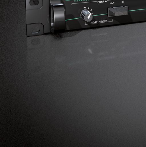
18 CHAPTER 4: Operation Signal Routing All four MADI input signals are fed to a routing matrix where they can be distributed to any output. This allows the SPLIT.CONVERTER to convert and distribute MADI signals: PORT A (ABCD) PORT B (ABCD) PORT C (ABCD) PORT D (ABCD) Encoder Turn the rotary control to the desired position to select the desired input source for output A. Encoder Turn the rotary control to the desired position to select the desired input source for output B. Encoder Turn the rotary control to the desired position to select the desired input source for output C. Encoder Turn the rotary control to the desired position to select the desired input source for output D. NOTE The ports are independent from each other, the MADI signals are not required to be in sync to each other. The routing is bit transparent and works without delay, even proprietary adaptions of MADI will pass through the unit in their native state. All common sample rates (up to 192 khz) and MADI formats (48k/96k frame, 56/64 channels) are supported. page 18 of 24 SPLIT.CONVERTER Manual - Version 2.0
19 CHAPTER 4: Operation Examples Format conversion of four MADI signals (coaxial < > optical) Signal C Signal D Signal A Signal B Signal distribution of one MADI signal (4 x optical, '1:4') Signal A Signal A Signal A Signal A Format conversion of four MADI signals (single mode <> multi-mode) Signal C Signal D Signal A Signal B SPLIT.CONVERTER Manual - Version 2.0 page 19 of 24
20 CHAPTER 5: Troubleshooting and Maintenance CHAPTER 5: Troubleshooting and Maintenance Troubleshooting To identify a possible defect with the device please consult the following table. If the fault cannot be resolved using these instructions, please contact your local DirectOut representative or visit support.directout.eu. Issue Possible reason Solution Device doesn t work. Optical port does not work. No signal at the output port. No signal at the output port. MADI signal at the input is not stable. Output port does not transmit the desired signal. Power supply is broken. Optic is dirty. Connections (input / output) are mixed up. Signal cable defective. Signal source is defective or bad signal condition (Jitter > 1 ns) - e.g. due to exceeded length or bad screening attenuation of signal cable. Wrong input selected. Check that the power supply switch is on, that the device is connected to the power supply and that the socket is working. Defective fuses must be exchanged by qualified service personal only. Use an air supply to carefully remove any dust. Never use objects for cleaning. Check the connections and change the cables if necessary. Check the routing matrix. Exchange the signal cable. Change the source or use appropriate cables (75 Ω, screening attenuation better than 85 db.) Change the input using the rotary control on the front panel. Maintenance To clean the device, use a soft, dry cloth. To protect the surface, avoid using cleaning agents. NOTE The device should be disconnected from the power supply during the cleaning process. page 20 of 24 SPLIT.CONVERTER Manual - Version 2.0
21 CHAPTER 6: Technical Data CHAPTER 6: Technical Data Dimensions Width 19 (483 mm) Height 1 RU (44.5 mm) Depth 10 (254 mm) Weight about 3.4 kg Power Consumption 25 W Power Supply 84 V V AC / 47 Hz - 63 Hz / Safety class 1 Fuses Fuse 250 V - 2 A (slow-blow) 2 fuses per power supply Environmental Conditions Operating temperature +5 C up to +45 C Relative humidity: 10% - 80%, non condensing MADI Port - (Version BNC/SC) 2 x BNC socket (1 x input / 1 x output) Impedance: 75 Ω 0.3 V up to 0.6 V (peak to peak) MADI Port - (Version BNC/SC or SC/SC) 2 x or 4 x SC socket FDDI (input / output) ISO/IEC Wave length: 1310 nm Multi mode 62.5/125 µm or 50/125 µm optional: single mode 9/125 µm Sample Rate 32 khz to 192 khz MADI Format (I/O) 48k Frame, 96k Frame 56 channel, 64 channel S/MUX 2/4 SPLIT.CONVERTER Manual - Version 2.0 page 21 of 24
22 Index Index B Bit-transparent W Warranty C Compatibility see Bit-transparent Conformity & Certificates CE RoHS WEEE Contact Contents Conventions... 5 D Defective Parts/Modules... 8 Dimensions E Environmental Conditions... 13, 21 F Feature Summary... 6 First Aid... 9 Fuses I Intended Operation S Sample Rate Signal Routing Examples Single-/Multi-mode Support T Technical Data Troubleshooting U Updates page 22 of 24 SPLIT.CONVERTER Manual - Version 2.0
23 Notes SPLIT.CONVERTER Manual - Version 2.0 page 23 of 24
24 DirectOut GmbH Leipziger Strasse 32 T: Mittweida Germany F:
EXBOX.BLDS. User s Manual. Version 1.3
 EXBOX.BLDS User s Manual Version 1.3 Copyright All rights reserved. Permission to reprint or electronically reproduce any document or graphic in whole or in part for any reason is expressly prohibited,
DirectOut Technologies
 DirectOut Technologies EXBOX.BLDS Manual Version 1.1 DirectOut Technologies Copyright Note Copyright All rights reserved. Permission to reprint or electronically reproduce any document or graphic in whole
DirectOut Technologies
 DirectOut Technologies D.O.TEC MA2CHBOX.XT Manual Version 1.2 DirectOut Technologies Copyright Note Copyright All rights reserved. Permission to reprint or electronically reproduce any document or graphic
AC Active Transmitter Combiner 8:1
 Active Transmitter Combiner 8:1 AC 3000 Bedienungsanleitung Instructions for use Notice d emploi Istruzioni per l uso Instrucciones para el uso Gebruiksaanwijzing 8 Active Transmitter Combiner 8:1 Instructions
EPA152/252/502. User Manual.
 EPA152/252/502 User Manual www.audac.eu ADDITIONAL INFORMATION This manual is put together with much care, and is as complete as could be on the publication date. However, updates on the specifications,
EPA104/254. User Manual.
 EPA104/254 User Manual www.audac.eu ADDITIONAL INFORMATION This manual is put together with much care, and is as complete as could be on the publication date. However, updates on the specifications, functionality
TETRIS 1000 High Impedance Active Probe. Instruction Manual
 TETRIS 1000 High Impedance Active Probe Instruction Manual Copyright 2015 PMK GmbH All rights reserved. Information in this publication supersedes that in all previously published material. Specifications
TETRIS User's Guide. High Impedance Active Probe DO177-1
 TETRIS 1500 High Impedance Active Probe User's Guide DO177-1 TETRIS 1500 Copyright 2010 Ltd. All rights reserved. Information in this publication supersedes that in all previously published material. Specifications
AC Active Transmitter Combiner 8:1
 Active Transmitter Combiner 8:1 AC 3000 Bedienungsanleitung Instructions for use Notice d emploi Istruzioni per l uso Instrucciones para el uso Gebruiksaanwijzing 8 Bedienungsanleitung...3 Instructions
Active Transmitter Combiner 8:1 AC 3200-II. Instruction manual
 Active Transmitter Combiner 8:1 AC 3200-II Instruction manual Contents Contents Important safety instructions... 2 The AC 3200-II active transmitter combiner 8:1... 4 Delivery includes... 4 Connection
PHV RO High Voltage Passive Probe. Instruction Manual
 PHV 1000-3-RO High Voltage Passive Probe Instruction Manual Copyright 2012 PMK GmbH All rights reserved. Information in this publication supersedes that in all previously published material. Specifications
PHV RO. High impedance passive probe. Features: CeramCore TM Hybrid Probe. Modular Construction. Coaxial Design
 High impedance passive probe Features: CeramCore TM Hybrid Probe Modular Construction Coaxial Design Interchangeable Spring Contact Tip Certificate of Calibration available on request Read-out BNC Connector
TMP40. User Manual.
 TMP40 User Manual www.audac.eu ADDITIONAL INFORMATION This manual is put together with much care, and is as complete as could be on the publication date. However, updates on the specifications, functionality
400 MHz Passive High-Voltage Probe R&S RT-ZH
 Manual 400 MHz Passive High-Voltage Probe R&S RT-ZH11 1409.7737.02 Printed in Germany Test and Measurment Manufacturer ROHDE & SCHWARZ For comprehensive information about Rohde and Schwarz, please visit
PHV 1000-RO High Voltage Passive Probe. Instruction Manual
 PHV 1000-RO High Voltage Passive Probe Instruction Manual Copyright 2014 PMK GmbH All rights reserved. Information in this publication supersedes that in all previously published material. Specifications
Operator s Manual. PP016 Passive Probe
 Operator s Manual PP016 Passive Probe 2017 Teledyne LeCroy, Inc. All rights reserved. Unauthorized duplication of Teledyne LeCroy documentation materials is strictly prohibited. Customers are permitted
DMP40. User Manual.
 DMP40 User Manual www.audac.eu ADDITIONAL INFORMATION This manual is put together with much care, and is as complete as could be on the publication date. However, updates on the specifications, functionality
Supplied in carry case with additional accessories The PHV 1000-RO is a 400 MHz, standard sized, 100:1 passive probe designed for instruments
 High impedance passive probe Features: CeramCore TM hybrid probe Modular construction Coaxial design Interchangeable spring contact tip Certificate of calibration available on request Read-out BNC connector
Installation instructions
 Installation instructions T70RX-03AIB, T70RX-03AWB, T70TX-02TTB, T70TX-03STB, T70TX-06TTB LANGUAGE: English (original) IM-T70-RX001-A01-EN CONTENTS Chapter 1: CUSTOMER INFORMATION 3 Chapter 2: PRODUCT
PKT 512A-RO High Impedance Passive Cable Divider
 PKT 512A-RO High Impedance Passive Cable Divider Instruction Manual Copyright 2011 PMK GmbH All rights reserved. Information in this publication supersedes that in all previously published material. Specifications
Connevans.info. DeafEquipment.co.uk. This product may be purchased from Connevans Limited secure online store at
 Connevans.info Solutions to improve the quality of life Offering you choice Helping you choose This product may be purchased from Connevans Limited secure online store at www.deafequipment.co.uk DeafEquipment.co.uk
TV Transmitter. User Guide Master
 TV Transmitter User Guide Master Content Before you start 3 Included in delivery 4 Components 4 Getting started 5 Connecting to power supply 5 Connecting to audio devices 6 Pairing the transmitter 7 Daily
Antenna Splitter ASA 1. Instruction manual
 Antenna Splitter ASA 1 Instruction manual Contents Contents Important safety instructions... 2 The ASA 1 active antenna splitter... 4 Combination possibilities of ASA 1/ASA 1-1G8... 5 Delivery includes...
AC 3. Active Antenna Combiner. Instruction manual
 AC 3 Active Antenna Combiner Instruction manual Contents Contents Important safety instructions... 2 The AC 3 active transmitter combiner... 4 Delivery includes... 4 Operating controls... 5 Block diagram...
TK 100 Probe Calibrator. Instruction Manual
 TK 100 Probe Calibrator Instruction Manual Copyright 2013 PMK GmbH All rights reserved. Information in this publication supersedes that in all previously published material. Specifications are subject
User s Manual. Miniature Passive Probe. IM EN 3rd Edition
 User s Manual Miniature Passive Probe IM 701946-01EN 3rd Edition Thank you for purchasing the miniature passive probe. This miniature passive probe is designed for user s safety and excellent easyto-use
Digital Function Generator
 Digital Function Generator 13654-99 PHYWE Systeme GmbH & Co. KG Robert-Bosch-Breite 10 37079 Göttingen Germany Tel. +49 (0) 551 604-0 Fax +49 (0) 551 604-107 E-mail info@phywe.de Operating Instructions
CIRCUIT-TEST ELECTRONICS
 USER'S MANUAL Sweep Function Generator with Counter SWF-8030 CIRCUIT-TEST ELECTRONICS www.circuittest.com TABLE OF CONTENTS SAFETY INFORMATION...page 3 INTRODUCTION... 4 SPECIFICATIONS... 5 FRONT PANEL
USER MANUAL V Valencia, Spain -
 USER MANUAL V.11.08 Valencia, Spain - www.lynxproaudio.com series Manufacturer LYNX Pro Audio S.L. Calle 7 - Pol. Ind. Picassent E-46220 Picassent (Valencia) CE CERTIFICACTION, EUROPEAN PRODUCT RoHS Directive
PA421B PA821B. Front Panels. Included Components. Features. Model Variations. Antenna Combiner
 Antenna Combiner WARNING: This product contains a chemical known to the State of California to cause cancer and birth defects or other reproductive harm. General Description Shure antenna combiners actively
PU202 Level converter & encoder signal generator without potential separation
 Operating Manual PU202 Level converter & encoder signal generator without potential separation Product features: Converts HTL signals from 10 up to 30 V (A / B / Z) into the corresponding TTL / RS422 format
Radio System Strobe Wizard Plus Freemask
 Radio System Strobe Wizard Plus Freemask User manual Translation of the original German user manual Doc. No.: 900.0509.00 Version: 09/2017 Contents Information about this manual and about the manufacturer...
INFRARED WIRELESS DISTRIBUTOR
 OPERATING INSTRUCTIONS INFRARED WIRELESS DISTRIBUTOR IR-700D Thank you for purchasing TOA's Infrared Wireless Distributor. Please carefully follow the instructions in this manual to ensure long, trouble-free
DPAfour125, DPAfour250 AMPLIFIERS. Operating Manual
 DPAfour125, DPAfour250 AMPLIFIERS Operating Manual Operating manual, DPA Series DPA-10UMS01-V01R04 version revision date 01 02 24-02-2012 www.ateis-europe.com ATEÏS Europe BV - Sydneystraat 42-3047BP ROTTERDAM
PMT 211A-RO. High impedance passive probe. Features: CeramCore TM Hybrid Probe. Modular Construction. Coaxial Design
 High impedance passive probe Features: CeramCore TM Hybrid Probe Modular Construction Coaxial Design Interchangeable Spring Contact Tip IC Contacting System 0.8 to 1.27 mm pitch The PMT 211A-RO is a 250
Mounting instruction and operating manual. Access Point (UK) HmIP-HAP-UK
 HmIP-HAP-UK") Mounting instruction and operating manual Access Point (UK) HmIP-HAP-UK Package contents Quantity Description 1 Homematic IP Access Point (UK) 1 Plug-in mains adapter 1 Network cable 2 Screws 2 Plugs 1
Mounting instruction and operating manual Access Point (UK) HmIP-HAP-UK Package contents Quantity Description 1 Homematic IP Access Point (UK) 1 Plug-in mains adapter 1 Network cable 2 Screws 2 Plugs 1
Thank you for purchasing a qualiton A20i power amplifier!
 Introduction Thank you for purchasing a qualiton A20i power amplifier! It is designed to deliver a high standard of musical performance. The innovation in engineering and manufacturing this product guarantees
LMM31. Dimmer Micromodule, 1 load USER MANUAL 20410/ LMM31 ALL RIGHTS RESERVED MARMITEK
 LMM31 Dimmer Micromodule, 1 load USER MANUAL 20410/20111019 LMM31 ALL RIGHTS RESERVED MARMITEK TABLE OF CONTENTS TABLE OF CONTENTS... 2 SAFETY WARNINGS... 3 HOW DOES MARMITEK X-10 WORK?... 4 ADRESSES...
PMT 221A. High impedance passive probe. Features: CeramCore TM Hybrid Probe. Modular Construction. Coaxial Design. Interchangeable Spring Contact Tip
 High impedance passive probe Features: CeramCore TM Hybrid Probe Modular Construction Coaxial Design Interchangeable Spring Contact Tip IC Contacting System 0.8 to 1.27 mm pitch Unbreakable Reed Switch
Cochlear Implants. I 100 detector box. User Manual. AW9750_4.0 (English)
") Cochlear Implants I 100 detector box User Manual AW9750_4.0 (English) Table of contents 1. Table of contents 2. INTRODUCTION 3 3. USE OF THE I 100 DETECTOR BOX 5 4. GETTING STARTED 6 I 100 detector box
Cochlear Implants I 100 detector box User Manual AW9750_4.0 (English) Table of contents 1. Table of contents 2. INTRODUCTION 3 3. USE OF THE I 100 DETECTOR BOX 5 4. GETTING STARTED 6 I 100 detector box
PHV 1000-RO. High impedance passive probe. Features: CeramCore TM hybrid probe. Modular construction. Coaxial design
 High impedance passive probe Features: CeramCore TM hybrid probe Modular construction Coaxial design Interchangeable spring contact tip Certificate of calibration available on request Read-out BNC connector
Operator s Manual. PP022 Passive Probe
 Operator s Manual PP022 Passive Probe 700 Chestnut Ridge Road Chestnut Ridge, NY, 10977-6499 Tel: (845) 425-2000, Fax: (845) 578 5985 teledynelecroy.com PP022 Passive Probe Instruction Manual 2017 Teledyne
SoundPals. DAC-24 User Guide. Stereo D-to-A converter
 SoundPals DAC-24 User Guide Stereo D-to-A converter Printing History SoundPals DAC-24 D-to-A converter Rev. N/C SEPTEMBER 2016 Printed in U.S.A. Part Number 08-2044-00 The information contained in this
E-800 power amplifier. user manual
 E-800 power amplifier user manual Musikhaus Thomann Thomann GmbH Hans-Thomann-Straße 1 96138 Burgebrach Germany Telephone: +49 (0) 9546 9223-0 E-mail: info@thomann.de Internet: www.thomann.de 20.05.2016,
TA 450 MK-X TA 600 MK-X TA 1050 MK-X TA 1400 MK-X TA 2400 MK-X power amplifier. user manual
 TA 450 MK-X TA 600 MK-X TA 1050 MK-X TA 1400 MK-X TA 2400 MK-X power amplifier user manual Musikhaus Thomann e. K. Treppendorf 30 96138 Burgebrach Germany Telephone: +49 (0) 9546 9223-0 E-mail: info@thomann.de
3B SCIENTIFIC PHYSICS
 3B SCIENTIFIC PHYSICS Analogue Multimeter Escola 100 1013527 Instruction sheet 12/15 SD/JS 1 Display with mirror scale 2 Slotted screw for zero calibration 3 Calibration trimmer for setting centre zero
E-400 power amplifier. user manual
 E-400 power amplifier user manual Musikhaus Thomann e.k. Treppendorf 30 96138 Burgebrach Germany Telephone: (09546) 9223-0 E-mail: info@thomann.de Internet: www.thomann.de 07.03.2014, ID: 173888 Table
Thank you for purchasing a qualiton A50i power amplifier!
 - 01 - Introduction Thank you for purchasing a qualiton A50i power amplifier! It is designed to deliver a high standard of musical performance. The innovation in engineering and manufacturing this product
AC/DC Current Probe GCP-100 QUICK START GUIDE ISO-9001 CERTIFIED MANUFACTURER
 AC/DC Current Probe GCP-100 QUICK START GUIDE ISO-9001 CERTIFIED MANUFACTURER This manual contains proprietary information, which is protected by copyright. All rights are reserved. No part of this manual
PROFESSIONAL STEREO AMPLIFIERS USER GUIDE
 PROFESSIONAL STEREO AMPLIFIERS USER GUIDE 967/9673 - September 00 - Version.0 ENGLISH Ti SERIES - Professional stereo amplifiers Page Ti SERIES - Professional stereo amplifiers ENGLISH - Safety information
LED PowerBlinder 4 ORDERCODE 41320
 LED PowerBlinder 4 ORDERCODE 41320 Congratulations! You have bought a great, innovative product from Showtec. The Showtec LED PowerBlinder brings excitement to any venue. Whether you want simple plug-&-play
Analogue Demo Multimeter ADM
 Analogue Demo Multimeter ADM 2 3820-0 PHYWE Systeme GmbH & Co. KG Robert-Bosch-Breite 0 D-37079 Göttingen Telefon +49 (0) 55 604-0 Fax +49 (0) 55 604-07 E-mail info@phywe.de Operating instructions The
POWER AMPLIFIER. Owner s Manual Mode d emploi Bedienungsanleitung Manual de instrucciónes CLIP SIGNAL TEMP PROTECTION POWER
 POWER AMPLIFIER Owner s Manual Mode d emploi Bedienungsanleitung Manual de instrucciónes TEMP PROTECTION POWER A CLIP SIGNAL B ON OFF M Introduction Thank you for purchasing a Yamaha C450/320/160 series
RIGOL. User s Guide. RP1000D Series High Voltage Differential Probe. Feb RIGOL Technologies, Inc
 User s Guide RP1000D Series High Voltage Differential Probe Feb. 2013 RIGOL Technologies, Inc Guaranty and Declaration Copyright 2012 RIGOL Technologies, Inc. All Rights Reserved. Trademark Information
TA MHz oscilloscope probe TA MHz oscilloscope probe
 TA375 100 MHz oscilloscope probe TA386 200 MHz oscilloscope probe User's Guide X1 X10 TA386 X1/X10 Max. 600 Vp Introduction This passive high-impedance oscilloscope probe is suitable for most oscilloscopes
INSTRUCTIONS MODELS AVX-TFR-MELF TEST JIG FOR USE WITH AVTECH AVR-EBF6-B FORWARD RECOVERY TEST SYSTEMS SERIAL NUMBER:
 A V T E C H E L E C T R O S Y S T E M S L T D. N A N O S E C O N D W A V E F O R M E L E C T R O N I C S S I N C E 1 9 7 5 P.O. BOX 265 OGDENSBURG, NY U.S.A. 13669-0265 TEL: 888-670-8729 (USA & Canada)
Operator s Manual. PP017 and PP018 Passive Probes
 Operator s Manual PP017 and PP018 Passive Probes 700 Chestnut Ridge Road Chestnut Ridge, NY, 10977-6499 Tel: (845) 425-2000, Fax: (845) 578 5985 teledynelecroy.com PP017 and PP018 Passive Probes Operator
SUBNANOSECOND PULSE GENERATOR PPG-2/1000 USER MANUAL
 SUBNANOSECOND PULSE GENERATOR PPG-2/1000 USER MANUAL 2015 Megaimpulse Ltd. Copyright 2015 MEGAIMPULSE Ltd. All Rights Reserved. MEGAIMPULSE LTD. PROVIDES THIS MANUAL "AS IS" WITHOUT WARRANTY OF ANY KIND,
i3speakers LX503 MK2 User Manual
 i3speakers LX503 MK2 User Manual Index Introduction 5 Precautions 6 Safety requirements 6 Caution servicing 7 EC Declaration of Conformity 7 Waste of Electrical and Electronic Equipment (WEEE) 7 Chapter
4 Channel Frequency Conscious Noise Gate. Operation Manual
 4 Channel Frequency Conscious Noise Gate Operation Manual June 2005 This page has been left intentionally blank for your notes Page 2 CONTENTS 1.0 OVERVIEW 4 2.0 DESCRIPTION OF CONTROLS 5-7 2.1 Bypass
15" 500W self-powered subwoofer
 15" 500W self-powered subwoofer USER GUIDE 10349 - Version 1 /01-2015 English SRSUB15A - 15" 500W self-powered subwoofer 1 - Safety information Important safety information This unit is intended for indoor
Operating Instructions PROFITEST H+E TECH. Diagnostics Unit for Electric Charging Stations (Type 2 Connector Socket and Plug) /3.
 /3.") Diagnostics Unit for Electric Charging Stations (Type 2 Connector Socket and Plug) 3-349-878-03 1/3.16 Opening the Instrument / Repairs The instrument may only be opened by authorized, trained personnel
Diagnostics Unit for Electric Charging Stations (Type 2 Connector Socket and Plug) 3-349-878-03 1/3.16 Opening the Instrument / Repairs The instrument may only be opened by authorized, trained personnel
Ver Tornado KT2 - KT2C KTL2 - KTL2C. USER GUIDE English KT2 KTL2 KT2C KTL2C
 Tornado KT2 - KT2C KTL2 - KTL2C USER GUIDE English KT2 KTL2 KT2C KTL2C TABLE of CONTENTS SYMBOLS... 3 1. INTRODUCTION... 4 2. KEY features... 4 4. APPLICATIONS... 4 3. OPTIONAL FEATURE... 4 5. SAFETY information...
INSTRUCTIONS MODEL AVC MONOCYCLE GENERATOR MODULE SERIAL NUMBER:
 A V T E C H E L E C T R O S Y S T E M S L T D. N A N O S E C O N D W A V E F O R M E L E C T R O N I C S S I N C E 1 9 7 5 P.O. BOX 265 OGDENSBURG, NY U.S.A. 13669-0265 TEL: 888-670-8729 (USA & Canada)
S5-ADU. Front... 4 Rear... 4
 Trantec ANTENNA DISTRIBUTOR INSTRUCTION MANUAL S5-ADU Thank you for purchasing TRANTEC Antenna Distributor. Please carefully follow the instructions in this manual to ensure long, trouble-free use of your
JACK 5.8. User manual. English. Version /2016
 JACK 5.8 User manual Version 4.0 06/2016 English A word of thanks Thank you for choosing stageclix! This unit has been designed with the professional musician in mind. All units are made with only the
USER GUIDE English. Tornado KT2 - KT2-HV KT2C - KT2C-HV KTL2 - KTL2-HV KTL2C - KTL2C-HV KT2 - KT2-HV KTL2 - KTL2-HV KT2C - KT2C-HV KTL2C - KTL2C-HV
 Tornado KT2 - KT2-HV KT2C - KT2C-HV KTL2 - KTL2-HV KTL2C - KTL2C-HV USER GUIDE English KT2 - KT2-HV KTL2 - KTL2-HV KT2C - KT2C-HV KTL2C - KTL2C-HV NEW All Tornado models are also available in a 70V version!
INTEGRATED VACUUM TUBE AMPLIFIER LM-508IA
 INTEGRATED VACUUM TUBE AMPLIFIER LM-508IA Table of Contents Thanks for choosing our Line Magnetic LM-508IA Integrated Amplifier as an important part of your music system and please read the manual carefully
NSPL-500. AIS/VHF antenna splitter. User Manual ENGLISH.
 NSPL-500 AIS/VHF antenna splitter User Manual ENGLISH www.bandg.com www.simrad-yachting.com www.lowrance.com Preface As Navico is continuously improving this product, we retain the right to make changes
Active Antenna Combiner ACA 1. Instruction manual
 Active Antenna Combiner ACA 1 Instruction manual Contents Contents Important safety instructions................... 2 The ACA 1 active antenna combiner.............. 4 Delivery includes...............................
USER. manual. Falco Systems WMA-100. High Voltage Amplifier DC - 500kHz
 USER manual Falco Systems WMA-100 High Voltage Amplifier DC - 500kHz Falco Systems WMA-100, High Voltage Amplifier DC - 500kHz High voltage: 20x amplification up to +175V and -175V output voltage with
Professional Power Amplifier HORIZON SERIES USER MANUAL. Content
 Professional Power Amplifier HORIZON SERIES USER MANUAL Thank you for buying this W Audio product. To take full advantage of this product, please keep this manual and read the operating instructions carefully.
As all PMK probes the PML 751-RO features CeramCore TM technology. The entire probe
 High impedance passive probe Features: 2.5 mm Diameter Tip Useable with any 50 Ω Instrument Interchangeable Spring Contact Tip IC Contacting System 0.5 to 1.27 mm pitch PMK introduces a new universal 10:1
Overview. Features. Technical Data Sheet 1 / 5. Power Amplifier XMV8140-D
 Overview Multi-channel power amplifiers with features designed specifically to benefit installation sound systems. Features Eight-channel power amp that can operate in both high-impedance (70V/100V line)
AM/FM SYNTHESIZER TUNER
 OPERATING INSTRUCTIONS AM/FM SYNTHESIZER TUNER DT-930 UL TABLE OF CONTENTS 1. IMPORTANT SAFETY INSTRUCTIONS... 2 2. SAFETY PRECAUTIONS... 2 3. INFORMATION TO THE USER... 3 4. GENERAL DESCRIPTION... 3 5.
PML 791-RO. High impedance passive probe. Features: 2.5 mm Diameter Tip. Coaxial Design. Interchangeable Spring Contact Tip
 High impedance passive probe Features: 2.5 mm Diameter Tip Coaxial Design Interchangeable Spring Contact Tip IC Contacting System 0.5 to 1.27 mm pitch PMK introduces a new universal 100:1 miniature probe
ProfiScale MULTI Multimeter
 1,5 V 9V 200 mv 600 V 200 ma 1/10 A ProfiScale MULTI Multimeter en Operating instructions BURG-WÄCHTER KG Altenhofer Weg 15 58300 Wetter Germany Introduction Want the reassurance of knowing whether current
Technical Documentation
 Technical Documentation for metratec QuasarMX HF RFID Reader Date: April 2015 Version: 1.4 Technical Documentation metratec QuasarMX Page 1 of 13 Table of Contents 1 General Information / Security Advice...3
Safety. Legal. stageclix is a trade mark of QDES works BV. QDES Works BV shall in no case be liable for damages arising from use of this product.
 Reference guide Version 1.0 04/2010 English Safety Do not open; no user serviceable parts inside. Guarantee invalid if opened. Unit is not waterproof. Keep away from water and other liquids. Maximum operating
User instructions Compound laboratory microscope
 KERN & Sohn GmbH Ziegelei 1 D-72336 Balingen E-mail: info@kern-sohn.com User instructions Compound laboratory microscope Tel: +49-[0]7433-9933-0 Fax: +49-[0]7433-9933-149 Internet: www.kern-sohn.com KERN
User instructions Compound laboratory microscope
 KERN & Sohn GmbH Ziegelei 1 D-72336 Balingen E-mail: info@kern-sohn.com User instructions Compound laboratory microscope Tel: +49-[0]7433-9933-0 Fax: +49-[0]7433-9933-149 Internet: www.kern-sohn.com KERN
SUNNY BEAM REPEATER Transmission Range Increase for Sunny Beam
 SUNNY BEAM REPEATER Transmission Range Increase for Sunny Beam User Manual SBeamRep-BEN091911 98-0002611 Version 1.1 EN SMA Solar Technology AG Table of Contents Table of Contents 1 Notes on this Manual..............................
WIRELESS DMX TRANSMITTER OR RECEIVER BOX (AIRDMX) USER GUIDE December 2012 Version 1.0
 USER GUIDE December 2012 Version 1.0") WIRELESS DMX TRANSMITTER OR RECEIVER BOX (AIRDMX) USER GUIDE 9966 - December 2012 Version 1.0 English AirBOX-ER1- Wireless DMX transmitter or receiver box (AirDMX) 1 - Safety information Important safety
WIRELESS DMX TRANSMITTER OR RECEIVER BOX (AIRDMX) USER GUIDE 9966 - December 2012 Version 1.0 English AirBOX-ER1- Wireless DMX transmitter or receiver box (AirDMX) 1 - Safety information Important safety
User Guide. Version 1.0.
 User Guide Version 1.0 www.focusrite.com TABLE OF CONTENTS OVERVIEW.... 3 Introduction...3 Features.................................................................... 3 Box Contents...4 Hardware Features...5
REVAMP4120T Instruction manual
 REVAMP4120T Instruction manual REVAMP4120T Instruction manual 3 REVAMP4120T manual 4 CLASS-D POWER AMPLIFIER IMPORTANT SAFETY INSTRUCTIONS 1. Read these instructions 2. Keep these instructions 3. Pay
OCTOPUS CONTROL STATION
 ICS-2000 USER MANUAL Item 71110 Version 1.0 Visit www.trust.com for the latest instructions OCTOPUS CONTROL STATION Read the manual carefully. Failure to follow these instructions can be dangerous. Incorrect
E-800 power amplifier. user manual
 E-800 power amplifier user manual Musikhaus Thomann e.k. Treppendorf 30 96138 Burgebrach Germany Telephone: +49 (0) 9546 9223-0 E-mail: info@thomann.de Internet: www.thomann.de 03.06.2013 Table of contents
10/12/15 inches 2-way amplified speakers with bass reflex
 10/12/15 inches 2-way amplified speakers with bass reflex USER GUIDE 10157 / 10158 / 10159 - January 2014 Version 1.0 English SR10A / SR12A / SR15A - 10/12/15 inches 2-way amplified speakers with bass
Always there to help you. Register your product and get support at AE2430. User manual
 Always there to help you Register your product and get support at www.philips.com/support AE2430 User manual Contents 1 Important 2 Safety 2 Notice 3 2 Your Portable Radio 5 Introduction 5 What s in the
Operating manual IMPORTANT! READ CAREFULLY BEFORE USE. KEEP FOR THE ENTIRE LIFE OF THE PRODUCT. Heat meters. Deltamess TKS-WM compact heat meter
 Operating manual IMPORTANT! READ CAREFULLY BEFORE USE. KEEP FOR THE ENTIRE LIFE OF THE PRODUCT. Heat meters Deltamess TKS-WM compact heat meter 1 Contents Safety and warranty... 3 Radio system... 3 Lithium
REVAMP4100 Instruction manual
 REVAMP4100 Instruction manual REVAMP4100 Instruction manual 3 REVAMP4100 manual 4 CLASS-D POWER AMPLIFIER IMPORTANT SAFETY INSTRUCTIONS 1. Read these instructions 2. Keep these instructions 3. Heed all
USER MANUAL. DC - 5MHz High Voltage Amplifier WMA V to +100V output. DC to -3dB large signal bandwidth. 1300V/µs slew rate typical
 DC - 5MHz High Voltage Amplifier WMA-320 www.falco-systems.com USER MANUAL -0V to +0V output DC to 5MHz @ -3dB large signal bandwidth 1300V/µs slew rate typical ±300mA Output current limit Stable with
Quadrupole Power Supply Unit QPS400-3
 http://www.cgc-instruments.de/ Quadrupole Power Supply Unit QPS400-3 Instruction Manual Document version 1.00, created on 12.07.2004 Technical Data Quadrupole Power Supply Unit 3 400 V QPS400-3 Version
On-Line Cardio Theater Wireless Digital Transmitter Installation and Instruction Manual
 On-Line Cardio Theater Wireless Digital Transmitter Installation and Instruction Manual Full installation instructions accompany your Cardio Theater equipment order. This On-Line version of our Installation/Instruction
FiberLink 4040 Series
 MANUAL FiberLink 4040 Series Four channels of audio over one single mode or multimode fiber. Installation and Operations Manual WWW.ARTEL.COM Contents Contents Welcome... 3 Features... 3 Package Contents...
DPA74/154 AUDAC PROFESSIONAL AUDIO EQUIPMENT. DPA74/154 Quad Channel Class-D Amplifier. User Manual & Installation Guide
 DPA74/154 PROFESSIONAL AUDIO EQUIPMENT DPA74/154 Quad Channel Class-D Amplifier AUDAC User Manual & Installation Guide AUDAC PROFESSIONAL AUDIO EQUIPMENT User Manual & Installation Guide AUDAC http://www.audac.eu
FS-7006PA FS-7012PA YA-7000 POWER AMPLIFIERS. AMPLIFIER AUTO SWITCHING MODULE (Optional) OPERATING INSTRUCTIONS
 OPERATING INSTRUCTIONS") OPERATING INSTRUCTIONS POWER AMPLIFIERS AMPLIFIER AUTO SWITCHING MODULE (Optional) FS-7006PA FS-7012PA YA-7000 Thank you for purchasing TOA's Power Amplifiers. Please carefully follow the instructions
OPERATING INSTRUCTIONS POWER AMPLIFIERS AMPLIFIER AUTO SWITCHING MODULE (Optional) FS-7006PA FS-7012PA YA-7000 Thank you for purchasing TOA's Power Amplifiers. Please carefully follow the instructions
USER MANUAL. Ultra-Low Noise High Voltage Amplifier WMA V to +150V output. 300µV rms output noise. 2mV output offset voltage
 Ultra-Low Noise High Voltage Amplifier WMA-28 280 www.falco falco-systems systems.com USER MANUAL -150V to +150V output 300µV rms output noise 2mV output offset voltage ±300mA Output current limit DC to
Always there to help you. Register your product and get support at AJ3200. Question? Contact Philips.
 Always there to help you Register your product and get support at www.philips.com/support Question? Contact Philips AJ3200 User manual Contents 1 Important 2 2 Your clock radio 2 Introduction 2 What's
Digital Clamp Meter Model: &
 Digital Clamp Meter Model: 72-7224 & 72-7226 1 SAFETY INFORMATION Please read these instructions carefully before use and retain for future reference. This meter is designed to meet IEC61010-1, 61010-2-032,