Radiofrequency Power Measurement
|
|
|
- Hortense Flynn
- 6 years ago
- Views:
Transcription
1 adiofrequency Power Measurement
2 Why not measure voltage?
3 Units and definitions Instantaneous power p(t)=v(t)i(t) DC: i(t)=i; v(t)=v P=VI=V²/=I² 1 t AC: P v( t) i( t) dt VI cos t 3

4 Average power 4

5 Envelope power and Peak envelope power 5

6 Pulse power 6
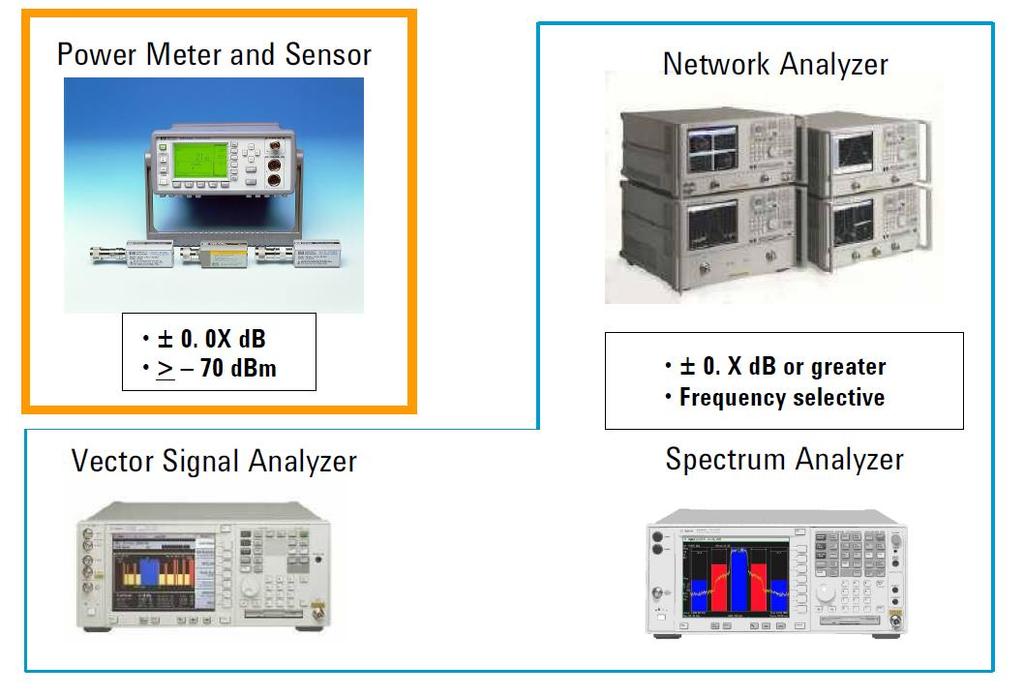
7 Instruments 7

8 Power meter and sensor 8
9 Sensor technologies Thermal Sensors: power is measured by estimating the heating (in different ways) Calorimeters Bolometers (thermistors) Thermocouples Non-linear Sensors: power is measured through a voltage measurement, after a non-linear conversion Diode 9

10 Calorimeters Calorimeters measure the heat produced by incident microwave radiation. They are typically constructed from a thermally insulating section of waveguide, a load and a temperature sensor such as a thermopile. They are in most cases the most accurate sensors available and so are used in national standards and some other calibration laboratories. Their main disadvantage is their extremely long time constant (often 0+ minutes) so they are not suitable for use in many measurement situations. P = power P C = specific heat = thermal resistance. M = fluid mass dt JCm dt (for water C= 1 kcal/kg C; J= ³ J/kcal), T 10

11 Twin load calorimeters Twin load calorimeters consist of two identical loads at the end of thermally insulating F line sections within a thermally insulating container. The temperature difference between the two loads is measured with temperature sensors. F power can be applied to one side of the calorimeter and DC power to the other. When the temperature difference between the two sides is zero the F and DC powers can be considered equivalent. P dt JCm dt T P T T t 0 mcj DC or F 11
12 Flow calorimeters Flow calorimeters are suitable for higher power measurements. They contain a quartz tube carrying flowing water. The power into the waveguide can be calculated by measuring the temperature rise of the water and the flow rate. The F power is given by: P=qC(T₂-T₁)J T₂-T₁ = temperature difference between input and output flow q = fluid mass flow rate C = specific heat J = ³ J/kcal The F heating is compared to DC heating by means of heating wires within the quartz tube that provide an identical temperature distribution. (substitution technique) 1
13 Bolometers The bolometers are resistors very sensitive to temperature variations. They are generally incorporated into a Wheatstone bridge. The F power measurement is generally carried out by substitution, thanks to the determination of the equivalent DC power by means of the measures of V and : 13
14 Working principle The bridge is balanced, therefore 1 = and b = 3 (= 0 for F matching) The power dissipated by the bolometer is: P DC A,0 VA,0 1 V b 4 0 first case, without F power With F power, the bolometers heats up and changes the resistance, the feedback loop acts on the DC voltage in order to keep the bridge balanced. kp F A,0 VA,1 1 V b 4 0 V A, 0 1 k P F V A,0 V 4k 0 A,1 effective efficiency F power substituted by DC power input F power F power 14
: T T β 1 1 exp 0 0 3 100 1 0 T C")
15 15 Sensing elements Thermistors (Negative Temperature Coefficient): esistance Temperature Detector (TD, PT100): T T β 1 1 exp T C T BT AT
16 Bolometers mounting Coaxial line bridge Coaxial line bridge Electrical and mechanical connection to the bridge insulating bridge 16
17 Measurement Errors Error due to the mismatch: if the assembly is not adapted, a part of the power to be measured is reflected (see next slides: available power). Substitution error: DC power and F power do not give rise to the same thermal effects in the bolometer. The differences in behavior in the two cases are attributable both to the skin effect and the different distribution of current along the wire which constitutes the sensitive element. To reduce the error of replacement is necessary that the resistive element has a length much smaller than the wavelength and a sufficiently reduced diameter so as to obtaina current distribution as uniform as possible Error due to the efficiency η: F Power dissipated by the bolometer Input F Power It takes into account the fact that a small part of the power is dissipated on the guide walls and on the supports of the bolometer. The total effect of replacing error and η efficiency is conglomerate in effective efficiency expression indicated by the symbol K 17
18 Available Power For a low frequency circuit, formed by a generator with impedance Z G and voltage e S (Thevenin equivalent), the power delivered to a load Z L is maximum when Z L = Z G * ( complex conjugate). This result is achieved by maximizing the variable e(v l i l ), as a function of Z L = L + jx L. Such power is defined as the available power of the generator. Turning to F, with no longer voltages and currents but traveling waves a and b, the condition of maximum delivered power shifts on reflection coefficients. 18
19 Available Power Generator: b s = g a s + b g Load: b L = L a L Lets consider the transmission line of negligible length: b s = a L and b L = a s. L g g L b a 1 L g L g L b b 1 a P L G L g L G L g L L L P b b a P Where P g is the power delivered to a matched load ( L =0, a s =0) g g b P
20 Available Power As for low frequency, we can demonstrate that P L is maximum when the load reflection coefficient is equal to the complex conjugate of the reflection coefficient of the generator: L G in this case the generator is in "conjugate matching", and the power transferred to the load is the maximum power-transferable = available power P 0 : * P 0 P g 1 G In conclusion, the relation between the power really delivered to the load and the available power is: P P L 1 g 1 L 0 1 g L 0
21 Calibration by microcalorimeter Microcalorimeters are used to calibrate thermistor type sensors. These sensors operate in a bridge circuit such that the power dissipated in the sensor should be constant whether or not F power is applied. The microcalorimeter measures the small temperature change caused by the extra losses in the input line of the sensor in the F case. A microcalorimeter consists of a thin-walled line section connected to the thermistor sensor being calibrated. A thermopile measures the temperature difference between the thermistor and a dummy sensor or temperature reference. By measuring the temperature change due to the F loss in the sensor and the input line, the efficiency of the sensor can be calculated. thermal shields Bolometers mountings Thermal insulation and thermopile F input 1
22 Balanced system
23 Thermocouple Thermocouples are based on the fact that dissimilar metals generate a voltage due to temperature differences at a hot and a cold junction of the two metals. Thomson electromotive force + Peltier effect = Seebeck electromotive force 3
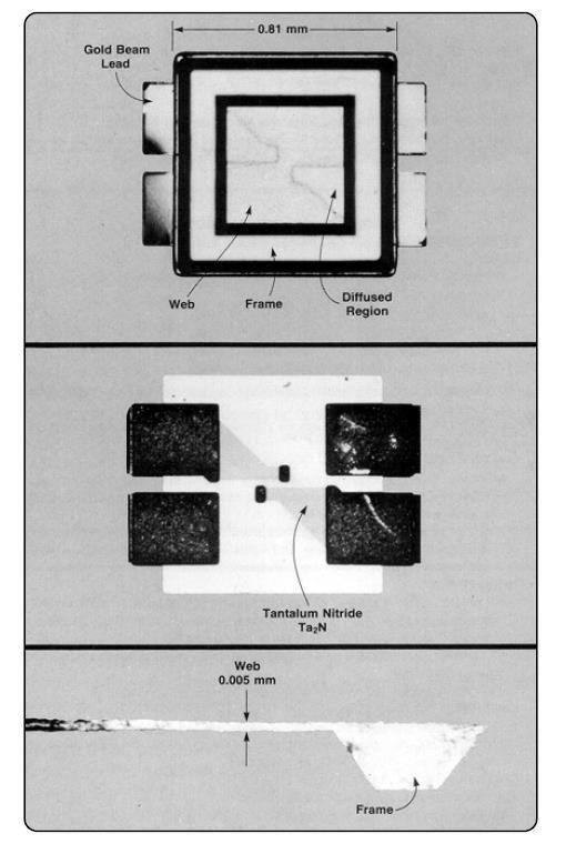
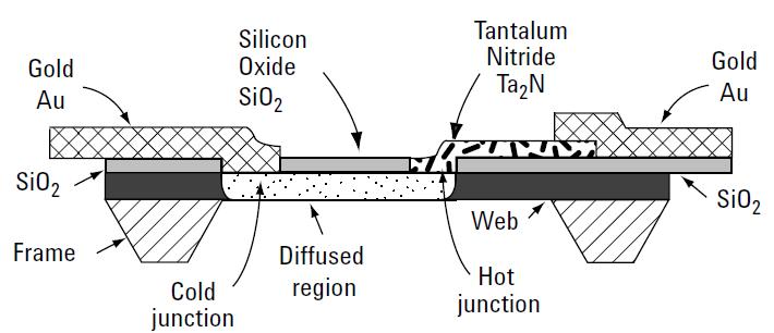
24 Thermocouple Sensor 4
25 Sensitivity Thermoelectric power 50 V/ C (Si-Ta N) The thermocouple has a thermal resistance 0.4 C/mW. Thus, the overall sensitivity of each thermocouple is 100 μv/mw. Two thermocouples in series yield a sensitivity of 160 μv/mw because of thermal coupling between the thermocouples. If the hot junction rises to 500 C, differential thermal expansion causes the chip to fracture. Thus, the sensor is limited to 300 mw maximum average power. The thermal resistance combines with the thermal capacity to form the thermal time constant of 10 μs. 5

26 Layout sensitivity to temperature Zero drift of thermocouple and thermistor power sensors due to being grasped by a hand. 6

27 Power meter for thermocouple sensors 7
28 Calibration and linearity In the case of thermistor sensors, the DC-substitution process keeps the tiny bead of thermistor, at a constant temperature, backing off bias power as F power is added. In the case of thermocouple sensors, as power is added, the detection microcircuit substrate with its terminating resistor runs at higher temperatures as the F power increases. This naturally induces minor deviations in the detection characteristic. Thermocouple power meters solve the need for sensitivity calibration by incorporating a 50 MHz power-reference oscillator whose output power is controlled with great precision (±0.4%). 8
29 I = I s [exp(v/nv T )-1], V T = kt/e 5 mv Diode sensor We can consider the simplified circuit shown in figure, with an input matching impedance 0 = 50 Ω In order to describe the diode behavior for low voltages, we can develop in series the exponential I 3 V V V I s... 3 nvt nvt 3! nvt If we consider an input sinusoidal voltage V, due to the input power 0, with V= V F sin(t) and thus P F V F 0 9
30 Diode sensor For very-low voltages V<< V T we can stop the series to the second term, neglecting the contribution of the higher-order terms. In this approximation, the DC component of the current, equal to the average value of I is given by: I DC I I V sin ( t) F F s I I T T T s s nv nv 4nV The differential resistance D of the diode is given by: 1 D I V V I 0 For a F diode, the saturation current has value close to 10 A, hence its differential resistance is equal to some kω: being D >> 0, the diode presence does not compromise the input line matching. The current I DC falls on the diode differential resistance D in parallel with the load, whose value is >> D. In this way we obtain an output DC voltage equal to: V DC I DC D D I s 4 V F nv T I s nv T V F 4nV T V 0 nv T P F 30
31 Diode sensor V DC 0 nv T P F We get a sensitivity between 0.5 mv/w and 1 mv/w. Considering a noise floor equal to 100 nv, for example, the minimum F input power is about -70 dbm, which is the noise background of this type of detectors. This discussion does not consider the non-ideality of the circuit and of the diode itself, and is mathematically valid only for input powers below -0 dbm, power level corresponding to the condition V < V T. 31
32 Power sensor and Meter signal path 3
33 Differential scheme Advantages: Thermoelectric voltages resulting from the joining of dissimilar metals, a serious problem below 60 dbm, are cancelled. Measurement errors caused by even-order harmonics in the input signal are suppressed due to the balanced configuration. A signal-to-noise improvement of 1 to db is realized by having two diodes. The detected output signal is doubled in voltage (quadrupled in power) while the noise output is doubled in power since the dominant noise sources are uncorrelated. Common-mode noise or interference riding on the ground plane is cancelled at the detector output. This is not F noise but metallic connection noises on the meter side. Diode technology provides some 3000 times (35 db) more efficient F-to-DC conversion compared to the thermocouple sensors 33
34 CW Power Sensor To achieve the expanded dynamic range of 90 db, the sensor/meter architecture depends on a data compensation algorithm that is calibrated and stored in an individual EEPOM in each sensor. The data algorithm stores information of three parameters, input power level vs frequency vs temperature for the range 10 MHz to 18 or 6.5 GHz and 70 to +0 dbm and 0 to 55 C. 34
35 CW Power Sensor The power meter uses the uploaded calibration data from each connected sensor to compensate for the three critical sensor parameters, power from 70 to +0 dbm, frequency for its specified band, and operating temperature 35
36 Diodes in series The F voltage on each diode is divided by N: VF V1D N P F 0 N diodes C V DC The generated DC current is the same for each diode: I DC I s V I 1D VF I 4 N DC,1diode s nv N 4nV T T The resistance of the series is: D, N diodes N D The voltage DC is: V DC I DC D I DC,1diode VDC,1diode, N diodes N D N N 0 nv T P N F The sensitivity is divided by N the noise power level grows of 10log 10 (N) but the maximum power for the quadratic region is increased by N [0log 10 (N)] The dynamic range is improved by 10log 10 (N) 36


37 Wide-dynamic-range power sensors The Agilent E-Series E9300 power sensors are implemented as a modified barrier integrated diode (MBID) with a two diode stack pair for the low power path ( 60 to 10 dbm), a resistive divider attenuator and a five diode stack pair for the high power path ( 10 to +0 dbm), 37

38 Linearity and calibration All thermocouple and diode power sensors require a power reference to absolute power, traceable to the manufacturer or national standards. Power meters accomplish this power traceability by use of a highly stable, internal 50 MHz power reference oscillator. The 1 mw reference power output is near the center of the dynamic range of thermocouple power sensors, but above the range of the sensitive diode sensor series. Therefore, a special 30 db calibration attenuator, designed for excellent precision at 50 MHz (1%), is supplied with each diode power sensor. 38
39 Problems with non-cw signals If the instantaneous power is much higher than the average power, the non linearity in the diode characteristic can induce measurement error. Problem with high crest factor signals (crest factor = peak value / rms value) Average Peak For non-cw signals with average powers between 0 and +0 dbm, use the thermocouple sensors for true average power sensing. 39


40 Peak and average power sensing 40
41 Peak and average power sensing 41
42 4 Limits in Frequency V DC 0 P F C 0 s d Cd V V IN d d d s D C s Z 1 The voltage on the diode junction (V) is d P d s d IN C s V V 1 1 d s d s P The non-linear effect expires with time constant BUT the sensor is no more matched before!! (When the diode impedance is close to 0 ) Example: for C d =0.1 pf, Z D 100Ω at f 16 GHz P C d d d d d d d d s D C j C j C j Z 1 1 1


43 Power ranges of different sensors 43
44 Mismatch of different power sensors 44

45 The Chain of Power Traceability 45
46 Bolometers (synthesis) 46
47 Thermocouples (synthesis) 47
48 Diode sensors (synthesis) 48
49 Diode sensor example 49
50 (mv) (mv) Diode sensor example 50

51 Diode sensor example 51

52 Diode sensor example 5
53 Diode sensor example 53
Agilent Fundamentals of RF and Microwave Power Measurements (Part 2) Power Sensors and Instrumentation
 Power Sensors and Instrumentation") Agilent Fundamentals of RF and Microwave Power Measurements (Part 2) Power Sensors and Instrumentation Application Note 1449-2 For user convenience, Agilent s Fundamentals of RF and Microwave Power Measurements,
Agilent Fundamentals of RF and Microwave Power Measurements (Part 2) Power Sensors and Instrumentation Application Note 1449-2 For user convenience, Agilent s Fundamentals of RF and Microwave Power Measurements,
Power Measurement Basics
 Back to Basics - 2006 Objectives On completion of this module, you will be able to: Explain the importance of power measurements Define the three basic types of power measurements Describe the power meter/sensor
Voltage Sensors URV5-Z
 Data sheet Version 05.00 Voltage Sensors URV5-Z May 2005 Universal voltage measurements from RF to microwaves The voltage sensors of the URV5-Z series are indispensable tools in RF and microwave laboratories,
Data Sheet. Peak, CW & Average. Power Sensors. Taking performance to a new peak
 Data Sheet Peak, CW & Average Power Sensors Taking performance to a new peak Peak, CW & Average Power Sensors The overall performance of a power meter dependents on the power sensor employed. Boonton has
Part Number I s (Amps) n R s (Ω) C j (pf) HSMS x HSMS x HSCH x
 n R s (Ω) C j (pf) HSMS x HSMS x HSCH x") The Zero Bias Schottky Detector Diode Application Note 969 Introduction A conventional Schottky diode detector such as the Agilent Technologies requires no bias for high level input power above one milliwatt.
The Zero Bias Schottky Detector Diode Application Note 969 Introduction A conventional Schottky diode detector such as the Agilent Technologies requires no bias for high level input power above one milliwatt.
Type Ordering Code Package TDA Q67000-A5168 P-DIP-18-5
 Video Modulator for FM-Audio TDA 5666-5 Preliminary Data Bipolar IC Features FM-audio modulator Sync level clamping of video input signal Controlling of peak white value Continuous adjustment of modulation
Dimensions in inches (mm) .268 (6.81).255 (6.48) .390 (9.91).379 (9.63) .045 (1.14).030 (.76) 4 Typ. Figure 1. Typical application circuit.
 .268 (6.81).255 (6.48) .390 (9.91).379 (9.63) .045 (1.14).030 (.76) 4 Typ. Figure 1. Typical application circuit.") LINEAR OPTOCOUPLER FEATURES Couples AC and DC signals.% Servo Linearity Wide Bandwidth, > KHz High Gain Stability, ±.%/C Low Input-Output Capacitance Low Power Consumption, < mw Isolation Test Voltage,
LINEAR OPTOCOUPLER FEATURES Couples AC and DC signals.% Servo Linearity Wide Bandwidth, > KHz High Gain Stability, ±.%/C Low Input-Output Capacitance Low Power Consumption, < mw Isolation Test Voltage,
Dhanalakshmi College of Engineering Department of ECE EC6701 RF and Microwave Engineering Unit 5 Microwave Measurements Part A
 Dhanalakshmi College of Engineering Department of ECE EC6701 RF and Microwave Engineering Unit 5 Microwave Measurements Part A 1. What is the principle by which high power measurements could be done by
Detection Beyond 100µm Photon detectors no longer work ("shallow", i.e. low excitation energy, impurities only go out to equivalent of
 Detection Beyond 100µm Photon detectors no longer work ("shallow", i.e. low excitation energy, impurities only go out to equivalent of 100µm) A few tricks let them stretch a little further (like stressing)
Differential Amplifier : input. resistance. Differential amplifiers are widely used in engineering instrumentation
 Differential Amplifier : input resistance Differential amplifiers are widely used in engineering instrumentation Differential Amplifier : input resistance v 2 v 1 ir 1 ir 1 2iR 1 R in v 2 i v 1 2R 1 Differential
Ten problems to solve before 6 December, 2010
 Ten problems to solve before 6 December, 2010 From Bengtsson: 1. (11.1) a) Calculate the total capacitance Ctot between the centre conductors of two coaxial cables, each 1 m long, separated by 10 cm. The
EQUIPMENT AND METHODS FOR WAVEGUIDE POWER MEASUREMENT IN MICROWAVE HEATING APPLICATIONS
 EQUIPMENT AND METHODS OR WAVEGUIDE POWER MEASUREMENT IN MICROWAVE HEATING APPLICATIONS John Gerling Gerling Applied Engineering, Inc. PO Box 580816 Modesto, CA 95358 USA ABSTRACT Various methods for waveguide
350MHz, Ultra-Low-Noise Op Amps
 9-442; Rev ; /95 EVALUATION KIT AVAILABLE 35MHz, Ultra-Low-Noise Op Amps General Description The / op amps combine high-speed performance with ultra-low-noise performance. The is compensated for closed-loop
Driver Amplifier for 7 Tesla MRI Smart Power Amplifier
 Driver Amplifier for 7 Tesla MRI Smart Power Amplifier presented by Kevin Kolpatzeck supervised by Prof. Dr.-Ing. Klaus Solbach Institute of Microwave and RF Technology University of Duisburg Essen Contents
Calibration Techniques for Precision Power Measurement in Semiconductor Proces Applications
 Calibration Techniques for Precision Power Measurement in Semiconductor Proces Applications MCS Standard Bird Directional Power Meter Lumped Element Directional Coupler Radio frequency power measurement
RF and Optical Bolometer
 RF and Optical Bolometer When RF energy is delivered to a resistive load it dissipates heat. If the load has a relatively poor thermal coupling to its surrounding environment its temperature will rise.
SWR/Return Loss Measurements Using System IIA
 THE GLOBAL SOURCE FOR PROVEN TEST SWR/Return Loss Measurements Using System IIA SWR/Return Loss Defined Both SWR and Return Loss are a measure of the divergence of a microwave device from a perfect impedance
Homework Assignment 03
 Homework Assignment 03 Question 1 (Short Takes), 2 points each unless otherwise noted. 1. Two 0.68 μf capacitors are connected in series across a 10 khz sine wave signal source. The total capacitive reactance
TL072 TL072A - TL072B
 A - B LOW NOISE J-FET DUAL OPERATIONAL AMPLIFIERS WIDE COMMON-MODE (UP TO V + CC ) AND DIFFERENTIAL VOLTAGE RANGE LOW INPUT BIAS AND OFFSET CURRENT LOW NOISE e n = 15nV/ Hz (typ) OUTPUT SHORT-CIRCUIT PROTECTION
MGM 3000X Q67000-A5179 P-DSO-20-1 (SMD) MGM 3000X Q67006-A5179 P-DSO-20-1 Tape & Reel (SMD)
 MGM 3000X Q67006-A5179 P-DSO-20-1 Tape & Reel (SMD)") Video Modulator for FM/AM-Audio MGM 3000X Bipolar IC Features FM- and AM-audio modulator Audio carrier output for suppression of harmonics Sync level clamping of video input signal Controlling of peak
Video Modulator for FM/AM-Audio MGM 3000X Bipolar IC Features FM- and AM-audio modulator Audio carrier output for suppression of harmonics Sync level clamping of video input signal Controlling of peak
LM13600 Dual Operational Transconductance Amplifiers with Linearizing Diodes and Buffers
 LM13600 Dual Operational Transconductance Amplifiers with Linearizing Diodes and Buffers General Description The LM13600 series consists of two current controlled transconductance amplifiers each with
VSWR MEASUREMENT APPLICATION NOTE ANV004.
 APPLICATION NOTE ANV004 Bötelkamp 31, D-22529 Hamburg, GERMANY Phone: +49-40 547 544 60 Fax: +49-40 547 544 666 Email: info@valvo.com Introduction: VSWR stands for voltage standing wave ratio. The ratio
Digital Potentiometers Selection Guides Don t Tell the Whole Story
 Digital Potentiometers Page - 1 - of 10 Digital Potentiometers Selection Guides Don t Tell the Whole Story by Herman Neufeld, Business Manager, Europe Maxim Integrated Products Inc., Munich, Germany Since
Study of the Long Term Performance on the Calibration Data of the Coaxial Thermistor Mounts up to 18 GHz
 Study MAPAN of the - Journal Long Term of Metrology Performance Society on of the India, Calibration Vol. 3, Data No., of 008; the Coaxial pp. 71-78 Thermistor Mounts up to 18 GHz Study of the Long Term
Dual Precision Operational Amplifier
 NJM79 Dual Precision Operational Amplifier FEATURES Precision V IO =6µV max. V IO =µv max. (Ta=-ºC to +8ºC) Low Offset Drift V IO / T=.9µV/ºC max. (Ta=-ºC to +8ºC) Specified for ±V and ±V operation CMR
Application Note 5525
 Using the Wafer Scale Packaged Detector in 2 to 6 GHz Applications Application Note 5525 Introduction The is a broadband directional coupler with integrated temperature compensated detector designed for
Precision Operational Amplifier
 Precision Operational Amplifier NJMOP77/NJMOP77 FEATURES Precision V IO =6μV max. V IO =μv max. (Ta= - to +8 ) PACKAGE OUTLINE Low Offset Drift V IO / T=.µV/ max. (Ta= - to +8 ) CMR db min. Low Noise V
Precision Operational Amplifier
 Precision Operational Amplifier NJM79 FEATURES Precision V IO =6µV max. V IO =µv max. (Ta=-ºC to +8ºC) Low Offset Drift ΔV IO /ΔT=.9µV/ºC max. (Ta=- to +8ºC) Specified for ±V and ±V operation CMR db min.
Investigation of a Voltage Probe in Microstrip Technology
 Investigation of a Voltage Probe in Microstrip Technology (Specifically in 7-tesla MRI System) By : Mona ParsaMoghadam Supervisor : Prof. Dr. Ing- Klaus Solbach April 2015 Introduction - Thesis work scope
Measurements 2: Network Analysis
 Measurements 2: Network Analysis Fritz Caspers CAS, Aarhus, June 2010 Contents Scalar network analysis Vector network analysis Early concepts Modern instrumentation Calibration methods Time domain (synthetic
Schottky Barrier Diode Video Detectors. Application Note 923
 Schottky Barrier Diode Video Detectors Application Note 923 I. Introduction This Application Note describes the characteristics of Agilent Technologies Schottky Barrier Diodes intended for use in video
Homework Assignment 06
 Question 1 (2 points each unless noted otherwise) Homework Assignment 06 1. True or false: when transforming a circuit s diagram to a diagram of its small-signal model, we replace dc constant current sources
Fundamentals of RF and Microwave Power Measurements. Application Note 64-1B
 Fundamentals of RF and Microwave Power Measurements Application Note 64-1B ic ss a Cl ts en m re u s ea m d er ate w d po up n d o e an t d no ise n v o ti y re a ic l pl ew p N a Table of Contents I.
Fundamentals of RF and Microwave Power Measurements. Application Note 64-1A. HP s classic application note on power measurements
 Fundamentals of RF and Microwave Power Measurements Application Note 64-1A HP s classic application note on power measurements Now completely revised and updated Application Note 64-1A Fundamentals of
1.25Gbps/2.5Gbps, +3V to +5.5V, Low-Noise Transimpedance Preamplifiers for LANs
 19-4796; Rev 1; 6/00 EVALUATION KIT AVAILABLE 1.25Gbps/2.5Gbps, +3V to +5.5V, Low-Noise General Description The is a transimpedance preamplifier for 1.25Gbps local area network (LAN) fiber optic receivers.
1 MHz to 8 GHz, 70 db Logarithmic Detector/Controller AD8318-EP
 Enhanced Product FEATURES Wide bandwidth: MHz to 8 GHz High accuracy: ±. db over db range (f
Improving Amplitude Accuracy with Next-Generation Signal Generators
 Improving Amplitude Accuracy with Next-Generation Signal Generators Generate True Performance Signal generators offer precise and highly stable test signals for a variety of components and systems test
Precision OPERATIONAL AMPLIFIER
 OPA77 查询 OPA77 供应商 OPA77 OPA77 Precision OPERATIONAL AMPLIFIER FEATURES LOW OFFSET VOLTAGE: µv max LOW DRIFT:.µV/ C HIGH OPEN-LOOP GAIN: db min LOW QUIESCENT CURRENT:.mA typ REPLACES INDUSTRY-STANDARD
PART MAX2605EUT-T MAX2606EUT-T MAX2607EUT-T MAX2608EUT-T MAX2609EUT-T TOP VIEW IND GND. Maxim Integrated Products 1
 19-1673; Rev 0a; 4/02 EVALUATION KIT MANUAL AVAILABLE 45MHz to 650MHz, Integrated IF General Description The are compact, high-performance intermediate-frequency (IF) voltage-controlled oscillators (VCOs)
LM13700 Dual Operational Transconductance Amplifiers with Linearizing Diodes and Buffers
 LM13700 Dual Operational Transconductance Amplifiers with Linearizing Diodes and Buffers General Description The LM13700 series consists of two current controlled transconductance amplifiers, each with
DUAL STEPPER MOTOR DRIVER
 DUAL STEPPER MOTOR DRIVER GENERAL DESCRIPTION The is a switch-mode (chopper), constant-current driver with two channels: one for each winding of a two-phase stepper motor. is equipped with a Disable input
DEPARTMENT OF ELECTRONICS AND COMMUNICATION ENGINEERING QUESTION BANK SUBJECT NAME & CODE: EC2403 & RF AND MICROWAVE ENGINEERING UNIT I
 FATIMA MICHAEL COLLEGE OF ENGINEERING & TECHNOLOGY Senkottai Village, Madurai Sivagangai Main Road, Madurai -625 020 An ISO 9001:2008 Certified Institution DEPARTMENT OF ELECTRONICS AND COMMUNICATION ENGINEERING
1 MHz to 10 GHz, 45 db Log Detector/Controller AD8319
 FEATURES Wide bandwidth: 1 MHz to 10 GHz High accuracy: ±1.0 db over temperature 45 db dynamic range up to 8 GHz Stability over temperature: ±0.5 db Low noise measurement/controller output VOUT Pulse response
ni.com Sensor Measurement Fundamentals Series
 Sensor Measurement Fundamentals Series How to Design an Accurate Temperature Measurement System Jackie Byrne Product Marketing Engineer National Instruments Sensor Measurements 101 Sensor Signal Conditioning
MICROWAVE ENGINEERING-II. Unit- I MICROWAVE MEASUREMENTS
 MICROWAVE ENGINEERING-II Unit- I MICROWAVE MEASUREMENTS 1. Explain microwave power measurement. 2. Why we can not use ordinary diode and transistor in microwave detection and microwave amplification? 3.
Dimensions in inches (mm) .021 (0.527).035 (0.889) .016 (.406).020 (.508 ) .280 (7.112).330 (8.382) Figure 1. Typical application circuit.
 .021 (0.527).035 (0.889) .016 (.406).020 (.508 ) .280 (7.112).330 (8.382) Figure 1. Typical application circuit.") IL Linear Optocoupler Dimensions in inches (mm) FEATURES Couples AC and DC signals.% Servo Linearity Wide Bandwidth, > khz High Gain Stability, ±.%/C Low Input-Output Capacitance Low Power Consumption,
IL Linear Optocoupler Dimensions in inches (mm) FEATURES Couples AC and DC signals.% Servo Linearity Wide Bandwidth, > khz High Gain Stability, ±.%/C Low Input-Output Capacitance Low Power Consumption,
Keysight Technologies 1 mw 50 MHz Power Reference Measurement with the N432A Thermistor Power Meter. Application Note
 Keysight Technologies 1 mw 50 MHz Power Reference Measurement with the N432A Thermistor Power Meter Application Note Introduction This application note explains the application procedure for using the
TL082 TL082A - TL082B
 TL082 TL082A - TL082B GENERAL PURPOSE J-FET DUAL OPERATIONAL AMPLIFIERS WIDE COMMON-MODE (UP TO V + CC ) AND DIFFERENTIAL VOLTAGE RANGE LOW INPUT BIAS AND OFFSET CURRENT OUTPUT SHORT-CIRCUIT PROTECTION
MAE334 - Introduction to Instrumentation and Computers. Final Exam. December 11, 2006
 MAE334 - Introduction to Instrumentation and Computers Final Exam December 11, 2006 o Closed Book and Notes o No Calculators 1. Fill in your name on side 2 of the scoring sheet (Last name first!) 2. Fill
444 Index. F Fermi potential, 146 FGMOS transistor, 20 23, 57, 83, 84, 98, 205, 208, 213, 215, 216, 241, 242, 251, 280, 311, 318, 332, 354, 407
 Index A Accuracy active resistor structures, 46, 323, 328, 329, 341, 344, 360 computational circuits, 171 differential amplifiers, 30, 31 exponential circuits, 285, 291, 292 multifunctional structures,
MICROWAVE MICROWAVE TRAINING BENCH COMPONENT SPECIFICATIONS:
 Microwave section consists of Basic Microwave Training Bench, Advance Microwave Training Bench and Microwave Communication Training System. Microwave Training System is used to study all the concepts of
Application Note 221. A New Coaxial Flow Calorimeter for Accurate RF Power Measurements up to 100 Watts and 1 GHz
 Application Note 221 A New Coaxial Flow Calorimeter for Accurate RF Power Measurements up to 100 Watts and 1 GHz Andrew S. Brush 1 Jefferson D. Lexa 2 Historically, there have been two methods for establishing
LF153 LF253 - LF353 WIDE BANDWIDTH DUAL J-FET OPERATIONAL AMPLIFIERS
 LF153 LF253 - LF353 WIDE BANDWIDTH DUAL J-FET OPERATIONAL AMPLIFIERS LOW POWER CONSUMPTION WIDE COMMON-MODE (UP TO V + CC ) AND DIFFERENTIAL VOLTAGE RANGE LOW INPUT BIAS AND OFFSET CURRENT OUTPUT SHORT-CIRCUIT
81 GHz to 86 GHz, E-Band Power Amplifier With Power Detector HMC8142
 Data Sheet 8 GHz to 86 GHz, E-Band Power Amplifier With Power Detector FEATURES GENERAL DESCRIPTION Gain: db typical The is an integrated E-band gallium arsenide (GaAs), Output power for db compression
EUA2011A. Low EMI, Ultra-Low Distortion, 2.5-W Mono Filterless Class-D Audio Power Amplifier DESCRIPTION FEATURES APPLICATIONS
 Low EMI, Ultra-Low Distortion, 2.5-W Mono Filterless Class-D Audio Power Amplifier DESCRIPTION The EUA2011A is a high efficiency, 2.5W mono class-d audio power amplifier. A new developed filterless PWM
Low voltage LNA, mixer and VCO 1GHz
 DESCRIPTION The is a combined RF amplifier, VCO with tracking bandpass filter and mixer designed for high-performance low-power communication systems from 800-1200MHz. The low-noise preamplifier has a
Chapter 12: Transmission Lines. EET-223: RF Communication Circuits Walter Lara
 Chapter 12: Transmission Lines EET-223: RF Communication Circuits Walter Lara Introduction A transmission line can be defined as the conductive connections between system elements that carry signal power.
INVENTION DISCLOSURE- ELECTRONICS SUBJECT MATTER IMPEDANCE MATCHING ANTENNA-INTEGRATED HIGH-EFFICIENCY ENERGY HARVESTING CIRCUIT
 INVENTION DISCLOSURE- ELECTRONICS SUBJECT MATTER IMPEDANCE MATCHING ANTENNA-INTEGRATED HIGH-EFFICIENCY ENERGY HARVESTING CIRCUIT ABSTRACT: This paper describes the design of a high-efficiency energy harvesting
Webinar Organizers. Ryan Shea. Don Miller. Joe Ryan. Support Specialist. Applications Specialist. Product Manager. Precision Digital Corporation
 Webinar Organizers Joe Ryan Product Manager Precision Digital Corporation Ryan Shea Applications Specialist Precision Digital Corporation Don Miller Support Specialist Precision Digital Corporation Agenda,
Microwave Circuit Design and Measurements Lab. INTRODUCTION TO MICROWAVE MEASUREMENTS: DETECTION OF RF POWER AND STANDING WAVES Lab #2
 EE 458/558 Microwave Circuit Design and Measurements Lab INTRODUCTION TO MICROWAVE MEASUREMENTS: DETECTION OF RF POWER AND STANDING WAVES Lab #2 The purpose of this lab is to gain a basic understanding
Limiter Diodes Features Description Chip Dimensions Model DOT Diameter (Typ.) Chip Number St l Style Inches 4 11
 Chip Number St l Style Inches 4 11") Features Low Loss kw Coarse Limiters 200 Watt Midrange Limiters 10 mw Clean Up Limiters 210 20 Description Alpha has pioneered the microwave limiter diode. Because all phases of manufacturing, from design
Features Low Loss kw Coarse Limiters 200 Watt Midrange Limiters 10 mw Clean Up Limiters 210 20 Description Alpha has pioneered the microwave limiter diode. Because all phases of manufacturing, from design
DUAL ULTRA MICROPOWER RAIL-TO-RAIL CMOS OPERATIONAL AMPLIFIER
 ADVANCED LINEAR DEVICES, INC. ALD276A/ALD276B ALD276 DUAL ULTRA MICROPOWER RAILTORAIL CMOS OPERATIONAL AMPLIFIER GENERAL DESCRIPTION The ALD276 is a dual monolithic CMOS micropower high slewrate operational
Micropower, Single-Supply, Rail-to-Rail, Precision Instrumentation Amplifiers MAX4194 MAX4197
 General Description The is a variable-gain precision instrumentation amplifier that combines Rail-to-Rail single-supply operation, outstanding precision specifications, and a high gain bandwidth. This
EXAM Amplifiers and Instrumentation (EE1C31)
") DELFT UNIVERSITY OF TECHNOLOGY Faculty of Electrical Engineering, Mathematics and Computer Science EXAM Amplifiers and Instrumentation (EE1C31) April 18, 2017, 9.00-12.00 hr This exam consists of four
DELFT UNIVERSITY OF TECHNOLOGY Faculty of Electrical Engineering, Mathematics and Computer Science EXAM Amplifiers and Instrumentation (EE1C31) April 18, 2017, 9.00-12.00 hr This exam consists of four
SIGNAL GENERATORS. MG3633A 10 khz to 2700 MHz SYNTHESIZED SIGNAL GENERATOR GPIB
 SYNTHESIZED SIGNAL GENERATOR MG3633A GPIB For Evaluating of Quasi-Microwaves and Measuring High-Performance Receivers The MG3633A has excellent resolution, switching speed, signal purity, and a high output
LINEAR IC APPLICATIONS
 1 B.Tech III Year I Semester (R09) Regular & Supplementary Examinations December/January 2013/14 1 (a) Why is R e in an emitter-coupled differential amplifier replaced by a constant current source? (b)
ECE-342 Test 1: Sep 27, :00-8:00, Closed Book. Name : SOLUTION
 ECE-342 Test 1: Sep 27, 2011 6:00-8:00, Closed Book Name : SOLUTION All solutions must provide units as appropriate. Use the physical constants and data as provided on the formula sheet the last page of
Differential-Mode Emissions
 Differential-Mode Emissions In Fig. 13-5, the primary purpose of the capacitor C F, however, is to filter the full-wave rectified ac line voltage. The filter capacitor is therefore a large-value, high-voltage
LM13700 Dual Operational Transconductance Amplifiers with Linearizing Diodes and Buffers
 LM13700 Dual Operational Transconductance Amplifiers with Linearizing Diodes and Buffers General Description The LM13700 series consists of two current controlled transconductance amplifiers, each with
QUAD 5V RAIL-TO-RAIL PRECISION OPERATIONAL AMPLIFIER
 ADVANCED LINEAR DEVICES, INC. ALD472A/ALD472B ALD472 QUAD 5V RAILTORAIL PRECISION OPERATIONAL AMPLIFIER GENERAL DESCRIPTION The ALD472 is a quad monolithic precision CMOS railtorail operational amplifier
OBSOLETE. High Performance, BiFET Operational Amplifiers AD542/AD544/AD547 REV. B
 a FEATURES Ultralow Drift: 1 V/ C (AD547L) Low Offset Voltage: 0.25 mv (AD547L) Low Input Bias Currents: 25 pa max Low Quiescent Current: 1.5 ma Low Noise: 2 V p-p High Open Loop Gain: 110 db High Slew
Coaxial Flow Calorimeter for Accurate RF Power Measurements up to 100 Watts and 1 GHz
 Test & Measurement Coaxial Flow Calorimeter for Accurate RF Power Measurements up to 100 Watts and 1 GHz Figure 1: Block diagram of the calorimeter used as the starting point for this project Andrew S.
KH300 Wideband, High-Speed Operational Amplifier
 Wideband, High-Speed Operational Amplifier Features -3dB bandwidth of 85MHz 00V/µsec slew rate 4ns rise and fall time 100mA output current Low distortion, linear phase Applications Digital communications
Noise Lecture 1. EEL6935 Chris Dougherty (TA)
") Noise Lecture 1 EEL6935 Chris Dougherty (TA) An IEEE Definition of Noise The IEEE Standard Dictionary of Electrical and Electronics Terms defines noise (as a general term) as: unwanted disturbances superposed
Noise Lecture 1 EEL6935 Chris Dougherty (TA) An IEEE Definition of Noise The IEEE Standard Dictionary of Electrical and Electronics Terms defines noise (as a general term) as: unwanted disturbances superposed
PART MAX4144ESD MAX4146ESD. Typical Application Circuit. R t IN- IN+ TWISTED-PAIR-TO-COAX CABLE CONVERTER
 9-47; Rev ; 9/9 EVALUATION KIT AVAILABLE General Description The / differential line receivers offer unparalleled high-speed performance. Utilizing a threeop-amp instrumentation amplifier architecture,
Optical Power Meter Basics
 Optical Power Meter Basics Introduction An optical power meter measures the photon energy in the form of current or voltage from an optical detector such as a semiconductor, a thermopile, or a pyroelectric
SIGNAL RECOVERY: Sensors, Signals, Noise and Information Recovery
 SIGNAL RECOVERY: Sensors, Signals, Noise and Information Recovery http://home.deib.polimi.it/cova/ 1 Signal Recovery COURSE OUTLINE Scenery preview: typical examples and problems of Sensors and Signal
A Broadband High-Efficiency Rectifier Based on Two-Level Impedance Match Network
 Progress In Electromagnetics Research Letters, Vol. 72, 91 97, 2018 A Broadband High-Efficiency Rectifier Based on Two-Level Impedance Match Network Ling-Feng Li 1, Xue-Xia Yang 1, 2, *,ander-jialiu 1
ULTRA-WIDEBAND DIFFERENTIAL VIDEO AMPLIFIER PACKAGE OUTLINE
 FEATURES BANDWIDTH AND TYPICAL GAIN 12 MHz at AVOL = 3 17 MHz at AVOL = 7 MHz at AVOL = ULTRA-WIDEBAND DIFFERENTIAL VIDEO AMPLIFIER VERY SMALL PHASE DELAY GAIN ADJUSTABLE FROM TO 3 NO FREQUENCY COMPENSATION
A Method for Gain over Temperature Measurements Using Two Hot Noise Sources
 A Method for Gain over Temperature Measurements Using Two Hot Noise Sources Vince Rodriguez and Charles Osborne MI Technologies: Suwanee, 30024 GA, USA vrodriguez@mitechnologies.com Abstract P Gain over
LM134/LM234/LM334 3-Terminal Adjustable Current Sources
 3-Terminal Adjustable Current Sources General Description The are 3-terminal adjustable current sources featuring 10,000:1 range in operating current, excellent current regulation and a wide dynamic voltage
Artisan Technology Group is your source for quality new and certified-used/pre-owned equipment
 Artisan Technology Group is your source for quality new and certified-used/pre-owned equipment FAST SHIPPING AND DELIVERY TENS OF THOUSANDS OF IN-STOCK ITEMS EQUIPMENT DEMOS HUNDREDS OF MANUFACTURERS SUPPORTED
14.2 Photodiodes 411
 14.2 Photodiodes 411 Maximum reverse voltage is specified for Ge and Si photodiodes and photoconductive cells. Exceeding this voltage can cause the breakdown and severe deterioration of the sensor s performance.
LF147 - LF247 LF347 WIDE BANDWIDTH QUAD J-FET OPERATIONAL AMPLIFIERS
 LF147 - LF247 LF347 WIDE BANDWIDTH QUAD J-FET OPERATIONAL AMPLIFIERS LOW POWER CONSUMPTION WIDE COMMON-MODE (UP TO V + CC ) AND DIFFERENTIAL VOLTAGE RANGE LOW INPUT BIAS AND OFFSET CURRENT OUTPUT SHORT-CIRCUIT
200 ma Output Current High-Speed Amplifier AD8010
 a FEATURES 2 ma of Output Current 9 Load SFDR 54 dbc @ MHz Differential Gain Error.4%, f = 4.43 MHz Differential Phase Error.6, f = 4.43 MHz Maintains Video Specifications Driving Eight Parallel 75 Loads.2%
Coaxial Power Standards
 Coaxial Power Standards (Thermistor Mounts) 0.1 MHz to 26.5 GHz FIGURE 1: MODEL F1109 (FEED-THROUGH MOUNT) FIGURE 2: MODEL M1110 (TERMINATING MOUNT) FIGURE 3: MODEL 1807A (FEED-THROUGH MOUNT WITH CASE)
Temperature References for Highest Accuracy Industrial Thermocouple Measurements
 Publication #531 Temperature References for Highest Accuracy Industrial Thermocouple Measurements Obtaining high-accuracy thermocouple temperature measurements requires instrumentation designed to minimize
EE/COE 152: Basic Electronics. Lecture 3. A.S Agbemenu. https://sites.google.com/site/agbemenu/courses/ee-coe-152
 EE/COE 152: Basic Electronics Lecture 3 A.S Agbemenu https://sites.google.com/site/agbemenu/courses/ee-coe-152 Books: Microelcetronic Circuit Design (Jaeger/Blalock) Microelectronic Circuits (Sedra/Smith)
THE TREND toward implementing systems with low
 724 IEEE JOURNAL OF SOLID-STATE CIRCUITS, VOL. 30, NO. 7, JULY 1995 Design of a 100-MHz 10-mW 3-V Sample-and-Hold Amplifier in Digital Bipolar Technology Behzad Razavi, Member, IEEE Abstract This paper
CDC7630/7631 and DDC2353/2354 Series: Zero Bias Silicon Schottky Barrier Detector Diodes in Hermetic Ceramic Packages
 DATA SHEET CDC7630/7631 and DDC2353/2354 Series: Zero Bias Silicon Schottky Barrier Detector Diodes in Hermetic Ceramic Packages Applications Microwave integrated circuits Detectors Features High sensitivity
NEW MODULATED THERMO-COUPLE SENSOR
 XVI IMEKO World Congress Vienna, AUSTRIA, 000, September 5-8 NEW MODULATED THERMO-COUPLE SENSOR K.Yagita*, K.Hino and J.Nakazoe Dept.of Electronics and Communication Eng. Faculty of Eng. Musashi Institute
150MHz phase-locked loop
 DESCRIPTION The NE568A is a monolithic phase-locked loop (PLL) which operates from Hz to frequencies in excess of 50MHz and features an extended supply voltage range and a lower temperature coefficient
1GHz low voltage LNA, mixer and VCO
 DESCRIPTION The is a combined RF amplifier, VCO with tracking bandpass filter and mixer designed for high-performance low-power communication systems from 800-1200MHz. The low-noise preamplifier has a
PowerAmp Design. PowerAmp Design PAD541 COMPACT POWER OP AMP
 PowerAmp Design COMPACT POWER OP AMP Rev E KEY FEATURES LOW COST HIGH VOLTAGE 00 VOLTS HIGH OUTPUT CURRENT 5 AMPS 50 WATT DISSIPATION CAPABILITY 00 WATT OUTPUT CAPABILITY 0.63 HEIGHT SIP DESIGN APPLICATIONS
HA-2600, HA Features. 12MHz, High Input Impedance Operational Amplifiers. Applications. Pinouts. Ordering Information
 HA26, HA26 September 998 File Number 292.3 2MHz, High Input Impedance Operational Amplifiers HA26/26 are internally compensated bipolar operational amplifiers that feature very high input impedance (MΩ,
CLC440 High Speed, Low Power, Voltage Feedback Op Amp
 CLC440 High Speed, Low Power, Voltage Feedback Op Amp General Description The CLC440 is a wideband, low power, voltage feedback op amp that offers 750MHz unity-gain bandwidth, 1500V/µs slew rate, and 90mA
Outline. Noise and Distortion. Noise basics Component and system noise Distortion INF4420. Jørgen Andreas Michaelsen Spring / 45 2 / 45
 INF440 Noise and Distortion Jørgen Andreas Michaelsen Spring 013 1 / 45 Outline Noise basics Component and system noise Distortion Spring 013 Noise and distortion / 45 Introduction We have already considered
HOME ASSIGNMENT. Figure.Q3
 HOME ASSIGNMENT 1. For the differential amplifier circuit shown below in figure.q1, let I=1 ma, V CC =5V, v CM = -2V, R C =3kΩ and β=100. Assume that the BJTs have v BE =0.7 V at i C =1 ma. Find the voltage
Power Meter NRVS. Power, level and voltage measurements from DC to 40 GHz
 Power Meter NRVS Power, level and voltage measurements from DC to 40 GHz Accurate, general-purpose, easy-to-use Intelligent measuring heads: just plug them in and measure DC frequency input for tracking
semiconductor p-n junction Potential difference across the depletion region is called the built-in potential barrier, or built-in voltage:
 Chapter four The Equilibrium pn Junction The Electric field will create a force that will stop the diffusion of carriers reaches thermal equilibrium condition Potential difference across the depletion