Digital Signal Processing
|
|
|
- Buck Bell
- 6 years ago
- Views:
Transcription
1 Digital Signal Processing Lecture 9 Discrete-Time Processing of Continuous-Time Signals Alp Ertürk alp.erturk@kocaeli.edu.tr
2 Analog to Digital Conversion Most real life signals are analog signals These analog signals are converted into digital signals for processing This conversion process consists of sampling, quantization and coding steps. Sampling is the the process of taking periodic samples from the continuous-time analog signal
3 Analog to Digital Conversion Sampling converts a continuous-time signal into a discretetime signal, but not into a digital signal This is because discrete-time signal can have an infinite number of amplitude values Quantization is the process of converting each amplitude value to the nearest of the predetermined amplitude values After representing each amplitude level by a code, the digital signal is obtained
4 Analog to Digital Conversion It is desired that the analog to digital conversion results in no loss of information from the signal For this, the number of samples has to be large enough However, a larger number of samples also means an increase in computation time Therefore, the smallest number of samples that do not cause an information loss is preferred. The sampling frequency that corresponds to this number is called the minimum sampling frequency
5 Analog to Digital Conversion The sampling process is defined as follows: x n = x a (nt s ), < n <, n integer T s is the sampling period f s = 1/T s is the sampling frequency
6 Ideal Impulse Sampling In an ideal sampling process, the analog signal is multiplied by an impulse train to take the instantaneous signal values x a (t) x s (t) i t = n= δ(t nt s )
7 Ideal Impulse Sampling Therefore the sampled signal is: x s t = x a t i t t = n= x a t δ(t nt s ) = n= x a nt s δ(t nt s )

8 Ideal Impulse Sampling
9 Ideal Impulse Sampling To determine the minimum sampling frequency, the frequency spectrum should be examined to observe whether there is a loss in the signal or not Note that multiplying two signals in time domain results in a convolution in the frequency domain Let s remember continuous-time Fourier transform
10 Ideal Impulse Sampling p t = e jω 0t CTFT 2πδ ω ω0 p t = k= a k e jkω 0t CTFT k= 2πa k δ ω kω 0 k= a k e jω0t is the Fourier series expansion for a periodic signal p(t). The coefficient are obtained as: a k = 1 T 0 T0 p(t) e jkω 0t dt
11 Ideal Impulse Sampling For the impulse train, these coefficients are: T s /2 a k = 1 T s Ts/2 n= δ(t nt s ) e jkω st dt T s /2 = 1 T s Ts/2 δ(t)e jkω st dt = 1 T s
12 Ideal Impulse Sampling The Fourier transform of an impulse train is also an impulse train defined in the integer multipliers of the sampling frequency δ(t nt s ) CTFT 2π n= T s n= δ(ω nω s ) In the frequency domain, sampling results in: X s ω = 1 2π X a ω 2π T s n= δ(ω nω s )
13 Ideal Impulse Sampling X s ω = 1 2π X a ω 2π T s n= δ(ω nω s ) = 1 T s n= X a (ω nω s ) The sampled signal s frequency spectrum is the frequency spectrum of the analog signal repeated at integer multipliers of the sampling frequency
14 Ideal Impulse Sampling Bandlimited signal 1 Xc j b 0 b 2 s s 0 P j s 2π/Ts X j s 2 s
15 Ideal Impulse Sampling ω s = 2ω m 1/Ts Xs j ω s < 2ω m 2 s s 1/Ts 0 X s j s 2 s Aliasing! ω s > 2ω m 2 s s 1/Ts 0 X s s j 2 s 2 s s 0 s 2 s
16 Ideal Impulse Sampling If the sampling frequency is exactly two times the maximum frequency component of the analog signal, then there is no overlap between the frequency components of the sampled signal, and no empty spaces between the frequency bands If the sampling frequency is larger than two times the maximum frequency component of the analog signal, then there is no overlap between the frequency components of the sampled signal, and there are empty spaces between the frequency bands
17 Ideal Impulse Sampling If the sampling frequency is smaller than two times the maximum frequency component of the analog signal, then the frequency components of the sampled signal overlap. In this case, there will be distortion in the time domain. This is caused when the number of samples is not enough to represent the signal accurately This is called aliasing
18 Ideal Impulse Sampling The condition that the sampling frequency is two times or larger than the maximum frequency component of the analog signal is named the Nyquist criterion The analog signal can be reconstructed from the sampled signal by a low-pass filter if it has been sampled according to the Nyquist criterion Hr j T s Xs j s 2 b 1/Ts 2 s s c 0 c s 2 s
")
19 CT to DT Conversion Continuous-time to discrete-time conversion can be considered as a multiplication by an impulse train, followed by a dicrete series converter for the impulse train The signal resulting from multiplying by an impulse train is: x s t = x c nt s δ(t nt s ) n=
20 CT to DT Conversion In frequency domain: X s ω = x s (t)e jωt dt = x c nt s δ(t nt s ) e jωt dt n= = n= x c nt s δ(t nt s )e jωt dt = n= x c nt s e jωnt s
21 CT to DT Conversion Note that: X s ω = n= x c nt s e jωnt s X e jω = n= x[n]e jωn = n= x c nt s e jωn In other words: X e jω = X s ω ω=ω/ts
22 CT to DT Conversion This can also be represented as: X e jω = X s ω ω=ω/ts = 1 T s k= X c (ω kω s ) ω=ω/ts = 1 T s k= X c Ω T s k 2π T s
23 CT to DT Conversion Ideal impulse sampled signal spectrum: j ω s > 2ω m 1/Ts Xs 2 s s 0 b s 2 s Discrete-time signal spectrum: ω s > 2ω m X e jω 1/Ts 4 2 T b s
24 CT to DT Conversion
25 DT to CT Conversion x[n] Convert from sequence to impulse train x s (t) Ideal reconstruction filter H r (jω) x(t) Hr j T s Xs j s 2 b 1/Ts 2 s s c 0 c s 2 s
26 DT to CT Conversion h r t sin t/ T t/ T s s
27 DT to CT Conversion A sampled continuous-time signal obtained from the discrete-time values is obtained as: x s t = n= x[n]δ(t nt s ) The continuous-time signal is obtained as: x c t = x s t h R (t) = x s (τ)h R (t τ)dτ
28 DT to CT Conversion A sampled continuous-time signal obtained from the discrete-time values is obtained as: x s t = n= x[n]δ(t nt s ) The continuous-time signal is obtained as: x c t = x s t h R (t) = x s (τ)h R (t τ)dτ
29 DT to CT Conversion x c t = x s (τ)h R (t τ)dτ = n= x[n]δ(τ nt s ) h R (t τ)dτ = n= x[n] δ(τ nt s )h R (t τ)dτ = n= x[n]h R (t nt s )
30 DT to CT Conversion An ideal reconstruction filter will have the impulse response: h R t = T s sin ω c t πt Then, x c t = n= x[n]h R (t nt s ) = n= x[n] sin π t nt s /T s π t nt s /T s = n= x n sinc t nt s /T s
31 DT to CT Conversion x c t = n= x n sinc t nt s /T s
32 Practical Limitations in Sampling There are three main practical limitations in this scheme 1) An ideal impulse train cannot be obtained in practice. Instead of an impulse train, a pulse train is commonly used. In other words, natural sampling or sample-and-hold sampling is used in practice instead of impulse sampling 2) An ideal filter cannot be obtained in practice. Because of this, the cut-off frequency of the filter is not sufficient to prevent aliasing when ω s = 2ω m as shown in the figure in the next slide

33 Practical Limitations in Sampling Because of this, in practice, the sampling should be conducted at a higher sampling frequency than the Nyquist rate.
34 Practical Limitations in Sampling 3) The signals used in practice are commonly time-limited and therefore cannot be band-limited. Signals that are not band limited result in aliasing in the frequency spectrum when sampled. To overcome this limitation, an anti-aliasing filter is used prior to sampling, in order to make the signal band-limited.
35 DT Processing of CT Signals Discrete-time processing of continuous-time signals enables the continuous-time signals to benefit from the advantages of discrete-time systems For this purpose, continuous-time signals are first converted to discrete-time, then processed in discrete-time systems, and finally the resulting signal is converted back into continuous-time
36 DT Processing of CT Signals As an example, let s consider a band-limited continuoustime signal, x(t), and apply this signal to a discrete-time ideal low-pass filter Let s consider a frequency spectrum such as the one below for x(t) ω m 0 ω m
37 DT Processing of CT Signals Then, if we sample this signal with a sampling frequency larger than the Nyquist rate, i.e. ω s > 2ω m, the sampled signal x s (t) s frequency spectrum becomes: ω s ω m 0 ω m ω s In discrete-time, x s [n] s frequency spectrum: X(e jω ) -2π 0 ω m T s π 2π 4π
38 DT Processing of CT Signals After that, let us consider the frequency response of the ideal low-pass filter with the cut-off frequency of Ω c 1 j H e c 0 The filtered signal y[n] s frequency spectrum then becomes: c
39 DT Processing of CT Signals If the discrete-time signal y s [n] is converted back into a continuous-time signal, the frequency spectrum becomes: T s Y s (ω) 1/ Ts 4 T s 2 T s T s T s c 0 T s c T s 2 4 T s T s
40 DT Processing of CT Signals When this signal is passed through a continuous-time reconstruction filter with a cut-off frequency ω c = π/t s, the following frequency spectrum is obtained: 1 Y(ω) T s c 0 c T s
41 DT Processing of CT Signals Example: An analog tv signal has a bandwidth of 5MHz. This signal is converted to discrete-time in 11 MHz sampling frequency, and processed through a discrete-time lowpass filter. If it is desired to cut off frequency components of the signal with higher frequencies than 3 MHz, what should be the cut-off frequency of the filter? f m = 5MHz f c = 3MHz ω m = 10π 10 6 rad/s ω c = 6π 10 6 rad/s ω c = Ω c T s Ω c = ω c T s = ω c f s = 6π = 6π 11
42 DT Processing of CT Signals Example: The ideal continuous-time differentiator system is defined by y c t = d dt x c(t) The corresponding frequency response is: H c jω = jω For processing band-limited signals, let us limit this to: H eff jω = jω, ω < π/t 0, ω π/t
43 DT Processing of CT Signals Example (continued): The corresponding discrete-time has the frequency : H c jω = jω T, Ω < π Suppose that this differentiator has the input x c t = cos ω 0 t with ω 0 < π/t The sampled input will be x n = cos Ω 0 n, Ω 0 = ω 0 T < π
44 DT Processing of CT Signals Example (continued): CTFT of x c t : X e jωt = 1 T k= πδ ω ω 0 kω s + πδ ω + ω 0 kω s Bandlimiting, we get: X e jωt = π T δ ω ω 0 + δ ω + ω 0, ω < π T
45 DT Processing of CT Signals Example (continued): X e jωt = π T δ ω ω 0 + δ ω + ω 0, ω < π T DTFT of x[n]: X e jω = π δ Ω Ω 0 + δ Ω + Ω 0, Ω < π The output: Y e jω = H e jω X e jω
46 DT Processing of CT Signals Example (continued): Y e jω = H e jω X e jω = jω T π δ Ω Ω 0 + δ Ω + Ω 0 = jω 0π T δ Ω Ω 0 jω 0π T δ Ω + Ω 0, Ω < π
47 DT Processing of CT Signals Example (continued): In continuous-time: Y r e jω = H r jω Y e jωt = TY e jωt = T jω 0π T δ ΩT Ω 0T jω 0π T δ ΩT + Ω 0T = jω 0 πδ ω ω 0 jω 0 πδ ω + ω 0 y r t = jω ejω 0t jω e jω 0t = ω 0 sin ω 0 t
48 Impulse Invariance x(t) H(e jω ) y(t) x(t) H s (ω) y(t)
49 Impulse Invariance At the output of the LTI discrete-time system, we have: Y e jω = X e jω H e jω At the output of the D/C converter, we have: Y ω = H R e jω Y e jω Ω=ωTs = H R e jω X e jω H e jω Ω=ωTs x[n] and x(t) are related in frequency as: X e jω = 1 T s k= X(ω kω s ) Ω=ωTs
50 Impulse Invariance The spectrum of the continuous-time y(t) is: Y ω = H R e jω 1 X(ω kω T s ) H e jω Ω=ωTs s k= The ideal reconstruction filter will have a cut-off frequency at ω c = π/t s, therefore only the frequency component at k=0 will pass: Y ω = H ejω Ω=ωTs X(ω) ω < π/t s 0 ω π/t s
51 Impulse Invariance Y ω = H ejω Ω=ωTs X(ω) ω < π/t s 0 ω π/t s Therefore, the continuous-time system has the frequency response: H s ω = H ejω Ω=ωTs ω < π/t s 0 ω π/t s
52 Impulse Invariance The discrete-time signal x n = x s (nt s ) is related to x s (t) in frequency as: X e jω = 1 X(ω kω T s ) s k= ω=ω/ts x s (t) is related to x n in frequency as: X s ω = T sx e jω Ω=ωTs ω < π/t s 0 ω π/t s The impulse responses are related by: h n = T s h s (nt s )
53 Changing Sampling Rate with DT Processing In order to change the sampling rate of a discrete-time signal, 1) The discrete-time signal can be converted into a continuous-time signal, which is then sampled at a different rate to convert into discrete-time 2) A discrete-time system can be directly used to change the sampling rate. This option is often preferred in practice
54 Changing Sampling Rate with DT Processing Decreasing the sampling rate in integer multipliers: x a n = x Mn = x MnT s The signal will be sampled by MT s period, instead of T s Down-sampling May result in information loss!
55 Changing Sampling Rate with DT Processing
56 Changing Sampling Rate with DT Processing The frequency spectrums will be: X e jω = 1 T s k= X(ω kω s ) ω=ω/ts X a e jω = 1 MT s k= X(ω kω s ) ω=ω/mts MΩ m should be smaller than or equal to π to prevent aliasing while down-sampling
57 Changing Sampling Rate with DT Processing X e jω Without aliasing: X a e jω With aliasing:
58 Changing Sampling Rate with DT Processing To prevent aliasing, a lowpass filter with a cut-off frequency of ω c = π/m is often used prior to down-sampling
59 Changing Sampling Rate with DT Processing x[n] Lowpass filter Ω c = π/m x f n M x a n = x f [nm]
60 Changing Sampling Rate with DT Processing Increasing the sampling rate in integer multipliers: x y n = x n/l, n = 0, ±L, ±2L, However, we need signal values at other n values also! First, let s consider the signal obtained as: x g n = x n/l n = 0, ±L, ±2L, 0 otherwise = k= x k δ[n kl]
61 Changing Sampling Rate with DT Processing The frequency spectrums will be related by: X g e jω = X e jωl
62 Changing Sampling Rate with DT Processing Then, we can use a lowpass filter with a gain of L and a cut-off frequency of ω c = π/l in order to obtain:
63 Changing Sampling Rate with DT Processing X e jω = 1 T s k= X(ω kω s ) ω=ω/ts X a e jω = L T s k= X(ω kω s ) ω=ωl/ts This process results in interpolation in the time-domain
64 Changing Sampling Rate with DT Processing x[n] L x g n Lowpass filter Gain = L Ω c = π/l x y n
65 Changing Sampling Rate with DT Processing Changing the sampling rate in a non-integer multiplier: This process can be considered as upsampling by L, and then downsampling by M, where L/M gives us the non-integer multiplier The process can be represented as: x[n] L x g n x y n Lowpass filter Gain = L Ω c = π/l Lowpass filter Ω c = π/m x f n M x a n
66 Changing Sampling Rate with DT Processing x[n] L x g n x y n Lowpass filter Gain = L Ω c = π/l Lowpass filter Ω c = π/m x f n M x a n Which can also be represented as: L Lowpass filter Gain = L Ω c = min( π L, π M) M
67 DT Processing of CT Signals Example: A music file has been sampled at f s = 32KHz. We want to list to this music file with a speech card operating at the frequency 12KHz. Assuming ideal filters, design the discrete-time system which makes the necessary sampling rate variation. f s f s = = 3 8 Lowpass filter 3 Gain = 3 8 Ω c = π 8
Sampling of Continuous-Time Signals. Reference chapter 4 in Oppenheim and Schafer.
 Sampling of Continuous-Time Signals Reference chapter 4 in Oppenheim and Schafer. Periodic Sampling of Continuous Signals T = sampling period fs = sampling frequency when expressing frequencies in radians
Sampling and Signal Processing
 Sampling and Signal Processing Sampling Methods Sampling is most commonly done with two devices, the sample-and-hold (S/H) and the analog-to-digital-converter (ADC) The S/H acquires a continuous-time signal
Signals and Systems. Lecture 13 Wednesday 6 th December 2017 DR TANIA STATHAKI
 Signals and Systems Lecture 13 Wednesday 6 th December 2017 DR TANIA STATHAKI READER (ASSOCIATE PROFFESOR) IN SIGNAL PROCESSING IMPERIAL COLLEGE LONDON Continuous time versus discrete time Continuous time
Sampling and Reconstruction of Analog Signals
 Sampling and Reconstruction of Analog Signals Chapter Intended Learning Outcomes: (i) Ability to convert an analog signal to a discrete-time sequence via sampling (ii) Ability to construct an analog signal
Signals and Systems Lecture 6: Fourier Applications
 Signals and Systems Lecture 6: Fourier Applications Farzaneh Abdollahi Department of Electrical Engineering Amirkabir University of Technology Winter 2012 arzaneh Abdollahi Signal and Systems Lecture 6
Chapter 6 CONTINUOUS-TIME, IMPULSE-MODULATED, AND DISCRETE-TIME SIGNALS. 6.6 Sampling Theorem 6.7 Aliasing 6.8 Interrelations
 Chapter 6 CONTINUOUS-TIME, IMPULSE-MODULATED, AND DISCRETE-TIME SIGNALS 6.6 Sampling Theorem 6.7 Aliasing 6.8 Interrelations Copyright c 2005- Andreas Antoniou Victoria, BC, Canada Email: aantoniou@ieee.org
ECE 301, final exam of the session of Prof. Chih-Chun Wang Saturday 10:20am 12:20pm, December 20, 2008, STEW 130,
 ECE 301, final exam of the session of Prof. Chih-Chun Wang Saturday 10:20am 12:20pm, December 20, 2008, STEW 130, 1. Enter your name, student ID number, e-mail address, and signature in the space provided
ECE503: Digital Signal Processing Lecture 1
 ECE503: Digital Signal Processing Lecture 1 D. Richard Brown III WPI 12-January-2012 WPI D. Richard Brown III 12-January-2012 1 / 56 Lecture 1 Major Topics 1. Administrative details: Course web page. Syllabus
Outline. Discrete time signals. Impulse sampling z-transform Frequency response Stability INF4420. Jørgen Andreas Michaelsen Spring / 37 2 / 37
 INF4420 Discrete time signals Jørgen Andreas Michaelsen Spring 2013 1 / 37 Outline Impulse sampling z-transform Frequency response Stability Spring 2013 Discrete time signals 2 2 / 37 Introduction More
PROBLEM SET 6. Note: This version is preliminary in that it does not yet have instructions for uploading the MATLAB problems.
 PROBLEM SET 6 Issued: 2/32/19 Due: 3/1/19 Reading: During the past week we discussed change of discrete-time sampling rate, introducing the techniques of decimation and interpolation, which is covered
Lecture 2 Review of Signals and Systems: Part 1. EE4900/EE6720 Digital Communications
 EE4900/EE6420: Digital Communications 1 Lecture 2 Review of Signals and Systems: Part 1 Block Diagrams of Communication System Digital Communication System 2 Informatio n (sound, video, text, data, ) Transducer
Signals and Systems Lecture 6: Fourier Applications
 Signals and Systems Lecture 6: Fourier Applications Farzaneh Abdollahi Department of Electrical Engineering Amirkabir University of Technology Winter 2012 arzaneh Abdollahi Signal and Systems Lecture 6
PROBLEM SET 5. Reminder: Quiz 1will be on March 6, during the regular class hour. Details to follow. z = e jω h[n] H(e jω ) H(z) DTFT.
![PROBLEM SET 5. Reminder: Quiz 1will be on March 6, during the regular class hour. Details to follow. z = e jω h[n] H(e jω ) H(z) DTFT.](/thumbs/96/129052141.jpg "PROBLEM SET 5. Reminder: Quiz 1will be on March 6, during the regular class hour. Details to follow. z = e jω h[n] H(e jω ) H(z) DTFT.") PROBLEM SET 5 Issued: 2/4/9 Due: 2/22/9 Reading: During the past week we continued our discussion of the impact of pole/zero locations on frequency response, focusing on allpass systems, minimum and maximum-phase
PROBLEM SET 5 Issued: 2/4/9 Due: 2/22/9 Reading: During the past week we continued our discussion of the impact of pole/zero locations on frequency response, focusing on allpass systems, minimum and maximum-phase
Midterm 1. Total. Name of Student on Your Left: Name of Student on Your Right: EE 20N: Structure and Interpretation of Signals and Systems
 EE 20N: Structure and Interpretation of Signals and Systems Midterm 1 12:40-2:00, February 19 Notes: There are five questions on this midterm. Answer each question part in the space below it, using the
Digital Processing of Continuous-Time Signals
 Chapter 4 Digital Processing of Continuous-Time Signals 清大電機系林嘉文 cwlin@ee.nthu.edu.tw 03-5731152 Original PowerPoint slides prepared by S. K. Mitra 4-1-1 Digital Processing of Continuous-Time Signals Digital
Lecture Schedule: Week Date Lecture Title
 http://elec3004.org Sampling & More 2014 School of Information Technology and Electrical Engineering at The University of Queensland Lecture Schedule: Week Date Lecture Title 1 2-Mar Introduction 3-Mar
Digital Processing of
 Chapter 4 Digital Processing of Continuous-Time Signals 清大電機系林嘉文 cwlin@ee.nthu.edu.tw 03-5731152 Original PowerPoint slides prepared by S. K. Mitra 4-1-1 Digital Processing of Continuous-Time Signals Digital
Multirate Digital Signal Processing
 Multirate Digital Signal Processing Basic Sampling Rate Alteration Devices Up-sampler - Used to increase the sampling rate by an integer factor Down-sampler - Used to increase the sampling rate by an integer
Digital Signal Processing (Subject Code: 7EC2)
") CIITM, JAIPUR (DEPARTMENT OF ELECTRONICS & COMMUNICATION) Notes Digital Signal Processing (Subject Code: 7EC2) Prepared Class: B. Tech. IV Year, VII Semester Syllabus UNIT 1: SAMPLING - Discrete time processing
CIITM, JAIPUR (DEPARTMENT OF ELECTRONICS & COMMUNICATION) Notes Digital Signal Processing (Subject Code: 7EC2) Prepared Class: B. Tech. IV Year, VII Semester Syllabus UNIT 1: SAMPLING - Discrete time processing
Islamic University of Gaza. Faculty of Engineering Electrical Engineering Department Spring-2011
 Islamic University of Gaza Faculty of Engineering Electrical Engineering Department Spring-2011 DSP Laboratory (EELE 4110) Lab#4 Sampling and Quantization OBJECTIVES: When you have completed this assignment,
Final Exam. EE313 Signals and Systems. Fall 1999, Prof. Brian L. Evans, Unique No
 Final Exam EE313 Signals and Systems Fall 1999, Prof. Brian L. Evans, Unique No. 14510 December 11, 1999 The exam is scheduled to last 50 minutes. Open books and open notes. You may refer to your homework
Spectrogram Review The Sampling Problem: 2π Ambiguity Fourier Series. Lecture 6: Sampling. ECE 401: Signal and Image Analysis. University of Illinois
 Lecture 6: Sampling ECE 401: Signal and Image Analysis University of Illinois 2/7/2017 1 Spectrogram Review 2 The Sampling Problem: 2π Ambiguity 3 Fourier Series Outline 1 Spectrogram Review 2 The Sampling
CS3291: Digital Signal Processing
 CS39 Exam Jan 005 //08 /BMGC University of Manchester Department of Computer Science First Semester Year 3 Examination Paper CS39: Digital Signal Processing Date of Examination: January 005 Answer THREE
Final Exam Solutions June 7, 2004
 Name: Final Exam Solutions June 7, 24 ECE 223: Signals & Systems II Dr. McNames Write your name above. Keep your exam flat during the entire exam period. If you have to leave the exam temporarily, close
Topic 2. Signal Processing Review. (Some slides are adapted from Bryan Pardo s course slides on Machine Perception of Music)
") Topic 2 Signal Processing Review (Some slides are adapted from Bryan Pardo s course slides on Machine Perception of Music) Recording Sound Mechanical Vibration Pressure Waves Motion->Voltage Transducer
Topic 2 Signal Processing Review (Some slides are adapted from Bryan Pardo s course slides on Machine Perception of Music) Recording Sound Mechanical Vibration Pressure Waves Motion->Voltage Transducer
DIGITAL SIGNAL PROCESSING. Chapter 1 Introduction to Discrete-Time Signals & Sampling
 DIGITAL SIGNAL PROCESSING Chapter 1 Introduction to Discrete-Time Signals & Sampling by Dr. Norizam Sulaiman Faculty of Electrical & Electronics Engineering norizam@ump.edu.my OER Digital Signal Processing
Digital communication
 Chapter 4 Digital communication A digital is a discrete-time binary m : Integers Bin = {0, 1}. To transmit such a it must first be transformed into a analog. The is then transmitted as such or modulated
Module 3 : Sampling and Reconstruction Problem Set 3
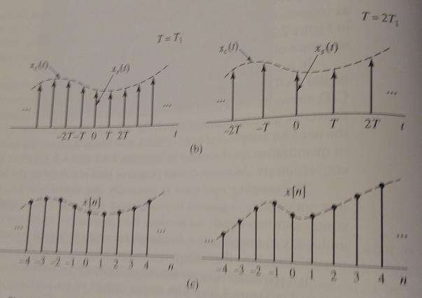
 Module 3 : Sampling and Reconstruction Problem Set 3 Problem 1 Shown in figure below is a system in which the sampling signal is an impulse train with alternating sign. The sampling signal p(t), the Fourier
Chapter-2 SAMPLING PROCESS
 Chapter-2 SAMPLING PROCESS SAMPLING: A message signal may originate from a digital or analog source. If the message signal is analog in nature, then it has to be converted into digital form before it can
Final Exam Solutions June 14, 2006
 Name or 6-Digit Code: PSU Student ID Number: Final Exam Solutions June 14, 2006 ECE 223: Signals & Systems II Dr. McNames Keep your exam flat during the entire exam. If you have to leave the exam temporarily,
EE 230 Lecture 39. Data Converters. Time and Amplitude Quantization
 EE 230 Lecture 39 Data Converters Time and Amplitude Quantization Review from Last Time: Time Quantization How often must a signal be sampled so that enough information about the original signal is available
Final Exam Practice Questions for Music 421, with Solutions
 Final Exam Practice Questions for Music 4, with Solutions Elementary Fourier Relationships. For the window w = [/,,/ ], what is (a) the dc magnitude of the window transform? + (b) the magnitude at half
6.003: Signals and Systems. Sampling
 6.003: Signals and Systems Sampling April 27, 200 Mid-term Examination #3 om orrow: W ednesday, A pril 2 8, 7 : 3 0-9 : 3 0 pm. No recitations tomorrow. Coverage: Lectures 20 Recitations 20 Homeworks Homework
Fourier Transform Analysis of Signals and Systems
 Fourier Transform Analysis of Signals and Systems Ideal Filters Filters separate what is desired from what is not desired In the signals and systems context a filter separates signals in one frequency
Multirate DSP, part 1: Upsampling and downsampling
 Multirate DSP, part 1: Upsampling and downsampling Li Tan - April 21, 2008 Order this book today at www.elsevierdirect.com or by calling 1-800-545-2522 and receive an additional 20% discount. Use promotion
THE CITADEL THE MILITARY COLLEGE OF SOUTH CAROLINA. Department of Electrical and Computer Engineering. ELEC 423 Digital Signal Processing
 THE CITADEL THE MILITARY COLLEGE OF SOUTH CAROLINA Department of Electrical and Computer Engineering ELEC 423 Digital Signal Processing Project 2 Due date: November 12 th, 2013 I) Introduction In ELEC
6.02 Fall 2012 Lecture #13
 6.02 Fall 2012 Lecture #13 Frequency response Filters Spectral content 6.02 Fall 2012 Lecture 13 Slide #1 Sinusoidal Inputs and LTI Systems h[n] A very important property of LTI systems or channels: If
EECE 301 Signals & Systems Prof. Mark Fowler
 EECE 31 Signals & Systems Prof. Mark Fowler Note Set #19 C-T Systems: Frequency-Domain Analysis of Systems Reading Assignment: Section 5.2 of Kamen and Heck 1/17 Course Flow Diagram The arrows here show
!"!#"#$% Lecture 2: Media Creation. Some materials taken from Prof. Yao Wang s slides RECAP
 Lecture 2: Media Creation Some materials taken from Prof. Yao Wang s slides RECAP #% A Big Umbrella Content Creation: produce the media, compress it to a format that is portable/ deliverable Distribution:
ECE 484 Digital Image Processing Lec 09 - Image Resampling
 ECE 484 Digital Image Processing Lec 09 - Image Resampling Zhu Li Dept of CSEE, UMKC Office: FH560E, Email: lizhu@umkc.edu, Ph: x 2346. http://l.web.umkc.edu/lizhu slides created with WPS Office Linux
Moving from continuous- to discrete-time
 Moving from continuous- to discrete-time Sampling ideas Uniform, periodic sampling rate, e.g. CDs at 44.1KHz First we will need to consider periodic signals in order to appreciate how to interpret discrete-time
Audio /Video Signal Processing. Lecture 1, Organisation, A/D conversion, Sampling Gerald Schuller, TU Ilmenau
 Audio /Video Signal Processing Lecture 1, Organisation, A/D conversion, Sampling Gerald Schuller, TU Ilmenau Gerald Schuller gerald.schuller@tu ilmenau.de Organisation: Lecture each week, 2SWS, Seminar
SAMPLING THEORY. Representing continuous signals with discrete numbers
 SAMPLING THEORY Representing continuous signals with discrete numbers Roger B. Dannenberg Professor of Computer Science, Art, and Music Carnegie Mellon University ICM Week 3 Copyright 2002-2013 by Roger
The University of Texas at Austin Dept. of Electrical and Computer Engineering Final Exam
 The University of Texas at Austin Dept. of Electrical and Computer Engineering Final Exam Date: December 18, 2017 Course: EE 313 Evans Name: Last, First The exam is scheduled to last three hours. Open
Multirate Signal Processing Lecture 7, Sampling Gerald Schuller, TU Ilmenau
 Multirate Signal Processing Lecture 7, Sampling Gerald Schuller, TU Ilmenau (Also see: Lecture ADSP, Slides 06) In discrete, digital signal we use the normalized frequency, T = / f s =: it is without a
y(n)= Aa n u(n)+bu(n) b m sin(2πmt)= b 1 sin(2πt)+b 2 sin(4πt)+b 3 sin(6πt)+ m=1 x(t)= x = 2 ( b b b b
= Aa n u(n)+bu(n) b m sin(2πmt)= b 1 sin(2πt)+b 2 sin(4πt)+b 3 sin(6πt)+ m=1 x(t)= x = 2 ( b b b b") Exam 1 February 3, 006 Each subquestion is worth 10 points. 1. Consider a periodic sawtooth waveform x(t) with period T 0 = 1 sec shown below: (c) x(n)= u(n). In this case, show that the output has the
Exam 1 February 3, 006 Each subquestion is worth 10 points. 1. Consider a periodic sawtooth waveform x(t) with period T 0 = 1 sec shown below: (c) x(n)= u(n). In this case, show that the output has the
Music 270a: Fundamentals of Digital Audio and Discrete-Time Signals
 Music 270a: Fundamentals of Digital Audio and Discrete-Time Signals Tamara Smyth, trsmyth@ucsd.edu Department of Music, University of California, San Diego October 3, 2016 1 Continuous vs. Discrete signals
NON-UNIFORM SIGNALING OVER BAND-LIMITED CHANNELS: A Multirate Signal Processing Approach. Omid Jahromi, ID:
 NON-UNIFORM SIGNALING OVER BAND-LIMITED CHANNELS: A Multirate Signal Processing Approach ECE 1520S DATA COMMUNICATIONS-I Final Exam Project By: Omid Jahromi, ID: 009857325 Systems Control Group, Dept.
! Multi-Rate Filter Banks (con t) ! Data Converters. " Anti-aliasing " ADC. " Practical DAC. ! Noise Shaping
 ! Data Converters. Anti-aliasing ADC. Practical DAC. ! Noise Shaping") Lecture Outline ESE 531: Digital Signal Processing! (con t)! Data Converters Lec 11: February 16th, 2017 Data Converters, Noise Shaping " Anti-aliasing " ADC " Quantization "! Noise Shaping 2! Use filter
Lecture Outline ESE 531: Digital Signal Processing! (con t)! Data Converters Lec 11: February 16th, 2017 Data Converters, Noise Shaping " Anti-aliasing " ADC " Quantization "! Noise Shaping 2! Use filter
ELE 635 Communication Systems. Assignment Problems and Solutions
 ELE 635 Communication Systems Assignment Problems and Solutions Winter 2015 CONTENTS Assignment 1: Signals and Signal Space 1.1 Problems... 1 1.2 Solutions... 3 Assignment 2: Analysis and Transmission
Principles of Baseband Digital Data Transmission
 Principles of Baseband Digital Data Transmission Prof. Wangrok Oh Dept. of Information Communications Eng. Chungnam National University Prof. Wangrok Oh(CNU) / 3 Overview Baseband Digital Data Transmission
Intuitive Guide to Fourier Analysis. Charan Langton Victor Levin
 Intuitive Guide to Fourier Analysis Charan Langton Victor Levin Much of this book relies on math developed by important persons in the field over the last 2 years. When known or possible, the authors have
Laboratory Assignment 5 Amplitude Modulation
 Laboratory Assignment 5 Amplitude Modulation PURPOSE In this assignment, you will explore the use of digital computers for the analysis, design, synthesis, and simulation of an amplitude modulation (AM)
Lecture 7 Frequency Modulation
 Lecture 7 Frequency Modulation Fundamentals of Digital Signal Processing Spring, 2012 Wei-Ta Chu 2012/3/15 1 Time-Frequency Spectrum We have seen that a wide range of interesting waveforms can be synthesized
Continuous vs. Discrete signals. Sampling. Analog to Digital Conversion. CMPT 368: Lecture 4 Fundamentals of Digital Audio, Discrete-Time Signals
 Continuous vs. Discrete signals CMPT 368: Lecture 4 Fundamentals of Digital Audio, Discrete-Time Signals Tamara Smyth, tamaras@cs.sfu.ca School of Computing Science, Simon Fraser University January 22,
Lecture 3 Review of Signals and Systems: Part 2. EE4900/EE6720 Digital Communications
 EE4900/EE6720: Digital Communications 1 Lecture 3 Review of Signals and Systems: Part 2 Block Diagrams of Communication System Digital Communication System 2 Informatio n (sound, video, text, data, ) Transducer
ANALOGUE AND DIGITAL COMMUNICATION
 ANALOGUE AND DIGITAL COMMUNICATION Syed M. Zafi S. Shah Umair M. Qureshi Lecture xxx: Analogue to Digital Conversion Topics Pulse Modulation Systems Advantages & Disadvantages Pulse Code Modulation Pulse
EE 123: Digital Signal Processing Spring Lecture 15 March 6
 EE 123: Digital Signal Processing Spring 2007 Lecture 15 March 6 Lecturer: Prof. Anant Sahai Scribe: Julia Owen 15.1 Outline These notes cover the following topics: Overlap-Add and Overlap-Save OFDM tricks
The University of Texas at Austin Dept. of Electrical and Computer Engineering Midterm #2
 The University of Texas at Austin Dept. of Electrical and Computer Engineering Midterm #2 Date: November 18, 2010 Course: EE 313 Evans Name: Last, First The exam is scheduled to last 75 minutes. Open books
ESE 531: Digital Signal Processing
 ESE 531: Digital Signal Processing Lec 11: February 20, 2018 Data Converters, Noise Shaping Lecture Outline! Review: Multi-Rate Filter Banks " Quadrature Mirror Filters! Data Converters " Anti-aliasing
Digital Filters IIR (& Their Corresponding Analog Filters) Week Date Lecture Title
 Week Date Lecture Title") http://elec3004.com Digital Filters IIR (& Their Corresponding Analog Filters) 2017 School of Information Technology and Electrical Engineering at The University of Queensland Lecture Schedule: Week Date
http://elec3004.com Digital Filters IIR (& Their Corresponding Analog Filters) 2017 School of Information Technology and Electrical Engineering at The University of Queensland Lecture Schedule: Week Date
YEDITEPE UNIVERSITY ENGINEERING FACULTY COMMUNICATION SYSTEMS LABORATORY EE 354 COMMUNICATION SYSTEMS
 YEDITEPE UNIVERSITY ENGINEERING FACULTY COMMUNICATION SYSTEMS LABORATORY EE 354 COMMUNICATION SYSTEMS EXPERIMENT 3: SAMPLING & TIME DIVISION MULTIPLEX (TDM) Objective: Experimental verification of the
ECE438 - Laboratory 7a: Digital Filter Design (Week 1) By Prof. Charles Bouman and Prof. Mireille Boutin Fall 2015
 By Prof. Charles Bouman and Prof. Mireille Boutin Fall 2015") Purdue University: ECE438 - Digital Signal Processing with Applications 1 ECE438 - Laboratory 7a: Digital Filter Design (Week 1) By Prof. Charles Bouman and Prof. Mireille Boutin Fall 2015 1 Introduction
Purdue University: ECE438 - Digital Signal Processing with Applications 1 ECE438 - Laboratory 7a: Digital Filter Design (Week 1) By Prof. Charles Bouman and Prof. Mireille Boutin Fall 2015 1 Introduction
18 Discrete-Time Processing of Continuous-Time Signals
 18 Discrete-Time Processing of Continuous-Time Signals Recommended Problems P18.1 Consider the system in Figure P18.1-1 for discrete-time processing of a continuoustime signal using sampling period T,
Chapter 7 Filter Design Techniques. Filter Design Techniques
 Chapter 7 Filter Design Techniques Page 1 Outline 7.0 Introduction 7.1 Design of Discrete Time IIR Filters 7.2 Design of FIR Filters Page 2 7.0 Introduction Definition of Filter Filter is a system that
ece 429/529 digital signal processing robin n. strickland ece dept, university of arizona ECE 429/529 RNS
 ece 429/529 digital signal processing robin n. strickland ece dept, university of arizona 2007 SPRING 2007 SCHEDULE All dates are tentative. Lesson Day Date Learning outcomes to be Topics Textbook HW/PROJECT
CMPT 318: Lecture 4 Fundamentals of Digital Audio, Discrete-Time Signals
 CMPT 318: Lecture 4 Fundamentals of Digital Audio, Discrete-Time Signals Tamara Smyth, tamaras@cs.sfu.ca School of Computing Science, Simon Fraser University January 16, 2006 1 Continuous vs. Discrete
II Year (04 Semester) EE6403 Discrete Time Systems and Signal Processing
 EE6403 Discrete Time Systems and Signal Processing") Class Subject Code Subject II Year (04 Semester) EE6403 Discrete Time Systems and Signal Processing 1.CONTENT LIST: Introduction to Unit I - Signals and Systems 2. SKILLS ADDRESSED: Listening 3. OBJECTIVE
Class Subject Code Subject II Year (04 Semester) EE6403 Discrete Time Systems and Signal Processing 1.CONTENT LIST: Introduction to Unit I - Signals and Systems 2. SKILLS ADDRESSED: Listening 3. OBJECTIVE
Concordia University. Discrete-Time Signal Processing. Lab Manual (ELEC442) Dr. Wei-Ping Zhu
 Dr. Wei-Ping Zhu") Concordia University Discrete-Time Signal Processing Lab Manual (ELEC442) Course Instructor: Dr. Wei-Ping Zhu Fall 2012 Lab 1: Linear Constant Coefficient Difference Equations (LCCDE) Objective In this
Concordia University Discrete-Time Signal Processing Lab Manual (ELEC442) Course Instructor: Dr. Wei-Ping Zhu Fall 2012 Lab 1: Linear Constant Coefficient Difference Equations (LCCDE) Objective In this
Week 1 Introduction of Digital Signal Processing with the review of SMJE 2053 Circuits & Signals for Filter Design
 SMJE3163 DSP2016_Week1-04 Week 1 Introduction of Digital Signal Processing with the review of SMJE 2053 Circuits & Signals for Filter Design 1) Signals, Systems, and DSP 2) DSP system configuration 3)
F I R Filter (Finite Impulse Response)
") F I R Filter (Finite Impulse Response) Ir. Dadang Gunawan, Ph.D Electrical Engineering University of Indonesia The Outline 7.1 State-of-the-art 7.2 Type of Linear Phase Filter 7.3 Summary of 4 Types FIR
F I R Filter (Finite Impulse Response) Ir. Dadang Gunawan, Ph.D Electrical Engineering University of Indonesia The Outline 7.1 State-of-the-art 7.2 Type of Linear Phase Filter 7.3 Summary of 4 Types FIR
Digital Signal Processing
 COMP ENG 4TL4: Digital Signal Processing Notes for Lecture #27 Tuesday, November 11, 23 6. SPECTRAL ANALYSIS AND ESTIMATION 6.1 Introduction to Spectral Analysis and Estimation The discrete-time Fourier
Frequency Division Multiplexing Spring 2011 Lecture #14. Sinusoids and LTI Systems. Periodic Sequences. x[n] = x[n + N]
![Frequency Division Multiplexing Spring 2011 Lecture #14. Sinusoids and LTI Systems. Periodic Sequences. x[n] = x[n + N]](/thumbs/88/116022205.jpg "Frequency Division Multiplexing Spring 2011 Lecture #14. Sinusoids and LTI Systems. Periodic Sequences. x[n] = x[n + N]") Frequency Division Multiplexing 6.02 Spring 20 Lecture #4 complex exponentials discrete-time Fourier series spectral coefficients band-limited signals To engineer the sharing of a channel through frequency
Frequency Division Multiplexing 6.02 Spring 20 Lecture #4 complex exponentials discrete-time Fourier series spectral coefficients band-limited signals To engineer the sharing of a channel through frequency
15 Discrete-Time Modulation
 15 Discrete-Time Modulation The modulation property is basically the same for continuous-time and discrete-time signals. The principal difference is that since for discrete-time signals the Fourier transform
ECE 429 / 529 Digital Signal Processing
 ECE 429 / 529 Course Policy & Syllabus R. N. Strickland SYLLABUS ECE 429 / 529 Digital Signal Processing SPRING 2009 I. Introduction DSP is concerned with the digital representation of signals and the
Discrete-time Signals & Systems
 Discrete-time Signals & Systems S Wongsa Dept. of Control Systems and Instrumentation Engineering, KMU JAN, 2010 1 Overview Signals & Systems Continuous & Discrete ime Sampling Sampling in Frequency Domain
CHAPTER 5. Additional Problems (a) The AM signal is defined by st () = A c. k a A c 1
 The AM signal is defined by st () = A c. k a A c 1") CHAPTER 5 Additional Problems 5.7 (a) The AM signal is defined by st () A c ( + k a mt ()) cos( ω c k a A c + ------------ + t cos( ω c To obtain 5% modulation, we choose k a, which results in the modulated
CHAPTER 5 Additional Problems 5.7 (a) The AM signal is defined by st () A c ( + k a mt ()) cos( ω c k a A c + ------------ + t cos( ω c To obtain 5% modulation, we choose k a, which results in the modulated
Experiment 8: Sampling
 Prepared By: 1 Experiment 8: Sampling Objective The objective of this Lab is to understand concepts and observe the effects of periodically sampling a continuous signal at different sampling rates, changing
Other Modulation Techniques - CAP, QAM, DMT
 Other Modulation Techniques - CAP, QAM, DMT Prof. David Johns (johns@eecg.toronto.edu) (www.eecg.toronto.edu/~johns) slide 1 of 47 Complex Signals Concept useful for describing a pair of real signals Let
Communication Channels
 Communication Channels wires (PCB trace or conductor on IC) optical fiber (attenuation 4dB/km) broadcast TV (50 kw transmit) voice telephone line (under -9 dbm or 110 µw) walkie-talkie: 500 mw, 467 MHz
Introduction to Discrete-Time Control Systems
 TU Berlin Discrete-Time Control Systems 1 Introduction to Discrete-Time Control Systems Overview Computer-Controlled Systems Sampling and Reconstruction A Naive Approach to Computer-Controlled Systems
Chapter 9. Chapter 9 275
 Chapter 9 Chapter 9: Multirate Digital Signal Processing... 76 9. Decimation... 76 9. Interpolation... 8 9.. Linear Interpolation... 85 9.. Sampling rate conversion by Non-integer factors... 86 9.. Illustration
QUESTION BANK. SUBJECT CODE / Name: EC2301 DIGITAL COMMUNICATION UNIT 2
 QUESTION BANK DEPARTMENT: ECE SEMESTER: V SUBJECT CODE / Name: EC2301 DIGITAL COMMUNICATION UNIT 2 BASEBAND FORMATTING TECHNIQUES 1. Why prefilterring done before sampling [AUC NOV/DEC 2010] The signal
Frequency Response Analysis
 Frequency Response Analysis Continuous Time * M. J. Roberts - All Rights Reserved 2 Frequency Response * M. J. Roberts - All Rights Reserved 3 Lowpass Filter H( s) = ω c s + ω c H( jω ) = ω c jω + ω c
Sistemas de Aquisição de Dados. Mestrado Integrado em Eng. Física Tecnológica 2015/16 Aula 3-29 de Setembro
 Sistemas de Aquisição de Dados Mestrado Integrado em Eng. Física Tecnológica 2015/16 Aula 3-29 de Setembro Aliasing Example fsig=101khz fsig=899 khz All sampled signals are equal! fsig=1101 khz 2 How to
Digital Signal Processing Fourier Analysis of Continuous-Time Signals with the Discrete Fourier Transform
 Digital Signal Processing Fourier Analysis of Continuous-Time Signals with the Discrete Fourier Transform D. Richard Brown III D. Richard Brown III 1 / 11 Fourier Analysis of CT Signals with the DFT Scenario:
ECE503: Digital Filter Design Lecture 9
 ECE503: Digital Filter Design Lecture 9 D. Richard Brown III WPI 26-March-2012 WPI D. Richard Brown III 26-March-2012 1 / 33 Lecture 9 Topics Within the broad topic of digital filter design, we are going
6.02 Fall 2013 Lecture #14
 6.02 Fall 2013 Lecture #14 Spectral content of signals via the DTFT 6.02 Fall 2013 Lecture 14 Slide #1 Determining h[n] from H(Ω) H(Ω) = m h[m]e jωm Multiply both sides by e jωn and integrate over a (contiguous)
Two-Dimensional Wavelets with Complementary Filter Banks
 Tendências em Matemática Aplicada e Computacional, 1, No. 1 (2000), 1-8. Sociedade Brasileira de Matemática Aplicada e Computacional. Two-Dimensional Wavelets with Complementary Filter Banks M.G. ALMEIDA
Sampling, interpolation and decimation issues
 S-72.333 Postgraduate Course in Radiocommunications Fall 2000 Sampling, interpolation and decimation issues Jari Koskelo 28.11.2000. Introduction The topics of this presentation are sampling, interpolation
ESE 531: Digital Signal Processing
 ESE 531: Digital Signal Processing Lec 10: February 15th, 2018 Practical and Non-integer Sampling, Multirate Sampling Signals and Systems Review 3 Lecture Outline! Review: Downsampling/Upsampling! Non-integer
Discrete-time Signals & Systems
 Discrete-time Signals & Systems S Wongsa Dept. of Control Systems and Instrumentation Engineering, KMU JAN, 2011 1 Overview Signals & Systems Continuous & Discrete ime Sampling Sampling in Frequency Domain
Chapter 3 Data Transmission COSC 3213 Summer 2003
 Chapter 3 Data Transmission COSC 3213 Summer 2003 Courtesy of Prof. Amir Asif Definitions 1. Recall that the lowest layer in OSI is the physical layer. The physical layer deals with the transfer of raw
HW 1 is due on tuesday. PPI is due on Thurs ( to hero by 5PM) Lab starts next week.
 Lab starts next week.") EECS 452 Lecture 2 Today: Sampling and reconstruction review FIR and IIR filters C5515 ezdsp Direct digital synthesis Reminders: HW 1 is due on tuesday. PPI is due on Thurs (email to hero by 5PM) Lab starts
EECS 452 Lecture 2 Today: Sampling and reconstruction review FIR and IIR filters C5515 ezdsp Direct digital synthesis Reminders: HW 1 is due on tuesday. PPI is due on Thurs (email to hero by 5PM) Lab starts
PYKC 27 Feb 2017 EA2.3 Electronics 2 Lecture PYKC 27 Feb 2017 EA2.3 Electronics 2 Lecture 11-2
 In this lecture, I will introduce the mathematical model for discrete time signals as sequence of samples. You will also take a first look at a useful alternative representation of discrete signals known
EE3723 : Digital Communications
 EE3723 : Digital Communications Week 11, 12: Inter Symbol Interference (ISI) Nyquist Criteria for ISI Pulse Shaping and Raised-Cosine Filter Eye Pattern Equalization (On Board) 01-Jun-15 Muhammad Ali Jinnah
ECE 556 BASICS OF DIGITAL SPEECH PROCESSING. Assıst.Prof.Dr. Selma ÖZAYDIN Spring Term-2017 Lecture 2
 ECE 556 BASICS OF DIGITAL SPEECH PROCESSING Assıst.Prof.Dr. Selma ÖZAYDIN Spring Term-2017 Lecture 2 Analog Sound to Digital Sound Characteristics of Sound Amplitude Wavelength (w) Frequency ( ) Timbre
Solution to Chapter 4 Problems
 Solution to Chapter 4 Problems Problem 4.1 1) Since F[sinc(400t)]= 1 modulation index 400 ( f 400 β f = k f max[ m(t) ] W Hence, the modulated signal is ), the bandwidth of the message signal is W = 00
Signal Processing for Speech Applications - Part 2-1. Signal Processing For Speech Applications - Part 2
 Signal Processing for Speech Applications - Part 2-1 Signal Processing For Speech Applications - Part 2 May 14, 2013 Signal Processing for Speech Applications - Part 2-2 References Huang et al., Chapter
Noise removal example. Today s topic. Digital Signal Processing. Lecture 3. Application Specific Integrated Circuits for
 Application Specific Integrated Circuits for Digital Signal Processing Lecture 3 Oscar Gustafsson Applications of Digital Filters Frequency-selective digital filters Removal of noise and interfering signals