CHAPTER 5 MITIGATION OF VOLTAGE SAG AND SWELL USING DIRECT CONVERTERS WITH MINIMUM SWITCH COUNT
|
|
|
- Horace Payne
- 6 years ago
- Views:
Transcription
1 75 CHAPTER 5 MITIGATION OF VOLTAGE SAG AND SWELL USING DIRECT CONVERTERS WITH MINIMUM SWITCH COUNT 5.1 INTRODUCTION Though many DVR topologies have been proposed based on direct converters, in the literature survey it is found that minimum number of switches used in each phase for compensation is four. In order to reduce the number of switches a new simplified topology with a series centre tapped transformer at the output side of the direct converter is presented. The direct converter is fabricated using only three bi-directional controlled switches. The DVR can properly compensate long-duration, balanced and unbalanced voltage sag and swell by taking power from the grid. The switches are driven by Pulse Width Modulation (PWM) signals. The simulation and the hardware results validate the idea that the proposed topology can mitigate sag and swell effectively. 5.2 PROPOSED TOPOLOGY WITH MINIMUM SWITCH COUNT Each DVR consists of a direct converter with a LC filter and a series centre tapped transformer with the turns-ratio of 1:1as shown in the Figure 5.1.
2 76 Figure 5.1 Proposed topology with minimum switches Figure 5.2 Bidirectional switch topology In this arrangement, the output voltage of the compensator can be either in-phase with the grid voltage or out of phase with the grid voltage. In the proposed topology, for the a-phase, when the switch Saa is put-on, supplies an in-phase voltage to the series transformer. When the switch Saa is put-on, the topology supplies the out-of-phase voltage to the series transformer. The switch Sga is connected across the series transformer. When the a-phase voltage is at the rated level, the switch Sga is kept closed, shortcircuiting the primary side of the series transformer. If the a-phase experiences sag, in order to generate the compensating voltage in phase with
3 77 the grid voltage, rnatively modulated. If it has swell, then in order to generate the compensating voltage out of phase with the grid voltage, the switches Saa and Sga are alternatively modulated. The compensating voltage is added to the grid voltage through the series transformer. Each DVR is structured by three bidirectional power switches. The topology of the bidirectional switch used is shown in the Figure 5.2. The switches are controlled by a simple PWM technique. Considering Figure 1, the following equation can be obtained: (5.1) In (5.1), l, g and con subscripts are used for the load, grid, and compensating quantities, respectively; the second subscript refers to the corresponding phases, respectively. Assuming sinusoidal waveforms, and considering only the a-phase, the voltages can be expressed as follows: (5.2) In the aforementioned equations, and are the peak values of load, grid, and injected voltages, respectively., is the phase angle of the injected voltage and is defined as follows: (5.3)
4 CONTROL PROCEDURE As mentioned in the first chapter, the voltage sag and swell is identified using single phase d-q theory. In this section switching pulse generation for the mitigation of sag and swell is explained in detail Voltage Sag Mitigation In order to compensate the voltage sag, it is necessary to inject voltage in-phase with the grid voltage. As the centre tapped series transformer gives output voltages of different polarity, the voltage which is in-phase with the grid voltage is chosen. This voltage is modulated using bi-directional switches and added in-phase with the grid voltage through a series transformer. Figure 5.3 Block diagram of switching pulse generation So if the voltage sag has occurred in a-phase, then the bidirectional A detailed block diagram for switching pulse generation to mitigate the voltage sag is shown in Figure 5.3. U gmax has been obtained from single phase d-q transform as explained in the first chapter. U ref is the desired terminal voltage, which is a user specified constant value set in the micro controller program.
5 79 The difference between the reference voltage U ref and the peak value of the grid voltage U gmax gives the amount of voltage sag or swell in the grid. The error signal is compared with the triangular carrier signal to generate the switching pulses. The pwm pulses are given to the corresponding switches through the logic gates as shown in the Figure Voltage Swell Mitigation In order to compensate the voltage swell, it is necessary to inject voltage out of phase with the grid voltage. So if there is voltage swell in phase modulated to mitigate the swell. Switching pulse generation is same as that of sag. 5.4 COMPENSATION RANGES OF THE DVR In this section, the voltage sag and swell compensation ranges for the proposed topology are calculated. It is assumed that the phase shift from V g to V con as well as the phase shift from V con to V l are negligible. The relationship between V g and V con (the filtered output voltage of the converter) can be expressed as (5.4) In (5.4 The above equation is valid because the transformation ratio of the series transformer is 1: Voltage Sag Compensation Range According to Figure 1, for voltage sag condition: (5.5)
6 80 Considering (5.4), (5.5) can be rewritten as follows: (5.6) The voltage sag percentage is defined by (5.7) Considering (5.6) and (5.7), the voltage sag percentage can be simplified to (5.8) 50% for D=1. It is seen that the maximum value of sag that can be compensated is Voltage Swell Compensation Range According to Figure 1, for voltage swell condition: (5.9) Considering (5.4), (5.9) can be simplified to (5.10) The voltage swell percentage is defined as follows: (5.11) Considering (5.10) and (5.11), the voltage swell percentage is simplified as follows: (5.12)
7 81 In this method the swell has been compensated by feeding the voltage from the same phase. From (5.12) it is observed that for D = 0.5, 100% voltage swell can be compensated. As the value of D is increased the topology can mitigate a greater amount of swell. It is not required to choose D =1 to mitigate large swells since sufficient voltage is available in the phase where swell is occurred. 5.5 SIMULATION RESULTS The MATLAB/SIMULINK software has been used for simulation. Three phase RL load (0.8 power factor lag, 240VA per phase,) were connected to the lines. The desired terminal voltage has been set at 60 V rms (1p.u), 50 Hz. The switching frequency of the converters is 8 khz. The filter is designed for a cut off frequency of 1000Hz with the value of inductance 1.732mH and the capacitance of 15uF according to the formula f = 1/ The ability of the DVR to mitigate balanced voltage sag of 50% in all the phases is shown in Figure 5.4. Mitigation of unbalanced voltage sag Figure 5.5. Figure 5.6. The compensation of balanced swell of 100% is illustrated in The ability of the DVR to mitigate unbalanced voltage swell of 100% in a-phase, 50% in b-phase, and 25% in c-phase can be observed in Figure 5.7.

")
 Load")


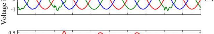
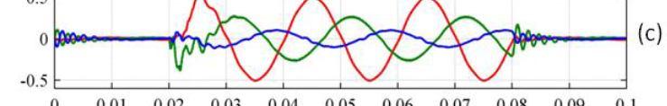
8 82 Figure 5.4 Mitigation of balanced voltage sag (a) Grid voltage (b) Load voltage (c) Compensation voltage produced by the DVR Figure 5.5 Mitigation of unbalanced voltage sag (a) Grid voltage (b) Load voltage (c) Compensation voltage produced by the DVR


")
")


9 83 Figure 5.6 Mitigation of balanced voltage swell. (a) Grid voltage (b) load Voltage (c) compensation voltage Figure 5.7 Mitigation of unbalanced voltage swell (a) Grid voltage (b) Load voltage (c) Compensation voltage produced by the DVR


10 EXPERIMENTAL RESULTS A three-phase DVR described in this chapter has been fabricated in order to verify the design procedure. A photograph of the experimental prototype is shown in the Figure 5.8. The PIC16F877A microcontroller has been used to generate the switching pulses. The rating of the centre tapped series transformer is 720VA, 120V with the transformation ratio of 1:1. IRFP460 power MOSFET switches of rating 500V, 20A were used to synthesize the direct converter. The hardware prototype has been designed for a rated voltage of 60V. Figure 5.8 Hardware prototype


 Compensated load voltage")
11 85 The ability of the DVR to mitigate balanced voltage sag of 50% in all the phases is shown in Figure 5.9. Figure 5.9 Balanced Sag Compensation (a) Grid voltage (b) Compensated load voltage (c) Compensating voltage produced by the DVR


 Grid")

12 86 The compensation of unbalanced voltage sag of 50% in a-phase, 25% in b- phase, and 10% in c-phase can be seen in Figure Figure 5.10 Unbalanced sag compensation (a) Grid voltage (b) Compensated load voltage (c) Compensating voltage produced by the DVR


 Compensating")
")

13 87 The compensation of voltage swell of 90% in a-phase, 100% in b-phase, and 115% in c-phase can be seen in Figure Figure 5.11 Swell compensation (a) Grid voltage (b) Compensated load voltage (c) Compensating voltage produced by the DVR 5.7 PERFORMANCE ANALYSIS Babai et al (2010) proposed a topology based on direct converter, with 5 switches per phase in which switches are controlled based on sampling process and it needs computations throughout a cycle. Using the control
14 88 algorithm explained, the compensation range of voltage sag is 0-33% and of the range for the voltage swell is 0-100%. Perez et al (2006) presented a topology for a single-phase DVR based on a single phase matrix converter with 4 switches per phase and the compensation range is 25% for voltage sags and 50% for swells. In this topology, during compensation 3 switches are modulated. So generation of switching pulses is complicated. Wang & Venkataramanan (2009) designed a DVR based on an indirect matrix converter for balanced voltage sags compensation of 60%. This topology needs flywheel energy storage element and the capability of the topology in voltage swell compensation has not been investigated. In this work, a centre tapped series transformer is used only with 3 bi-directional switches such that the only 2 switches are modulated during compensation. So the switching loss is less and switching pulse generation is also easier. In this topology switches are controlled by ordinary PWM. As a result, computation is avoided, control is simpler and 50% of voltage sag and unlimited quantity of voltage swell is compensated as mentioned in Table 5.1.
15 89 Table 5.1 Comparison of various DVR topologies S. No Converter Topology Compensation Range Sag Swell PWM Technique Used No of Switches 1 Direct Converter topology by Babai et al (2010) 33% 100% Pulse Width is computed during each switching period 5 2 Matrix Converter topology by perez et al (2006) 25% 50% Ordinary PWM 4 3 Indirect matrix Converter with Flywheel energy Storage by Wang & Venkataramanan (2009) 60% Nil Ordinary PWM 5 4 Proposed converter 50% Unlimit ed Ordinary PWM SUMMARY A three-phase DVR based on direct converters has been presented which do not require the dc link as in the conventional DVRs. The absence of the dc link reduces the cost, weight, and volume of the DVR and also avoids the maintenance of energy storage devices. The DVR in each of the three phase lines is constructed using only three bidirectional switches. The control of DVR is done by using a very simple PWM procedure. The DVR is able to mitigate 50% of balanced and unbalanced voltage sag, unlimited quantity of balanced and unbalanced voltage swell effectively. The topology presented uses only three switches, with one centre tapped series transformer for each phase for effective compensation with simple control logic.
CHAPTER 6 MITIGATION OF VOLTAGE SAG, SWELL AND SINGLE PHASE OUTAGE USING MULTI WINDING TRANSFORMER
 90 CHAPTER 6 MITIGATION OF VOLTAGE SAG, SWELL AND SINGLE PHASE OUTAGE USING MULTI WINDING TRANSFORMER 6.1 INTRODUCTION From the literature survey it is observed that the DVRs based on direct converters
Mitigation of Voltage Sag and Swell Using Direct Converters with Minimum Switch Count
 1314 Journal of Power Electronics, Vol. 14, No. 6, pp. 1314-1321, November 2014 JPE 14-6-25 http://dx.doi.org/10.6113/jpe.2014.14.6.1314 ISSN(Print): 1598-2092 / ISSN(Online): 2093-4718 Mitigation of Voltage
MITIGATION OF VOLTAGE SAGS/SWELLS USING DYNAMIC VOLTAGE RESTORER (DVR)
") VOL. 4, NO. 4, JUNE 9 ISSN 89-668 6-9 Asian Research Publishing Network (ARPN). All rights reserved. MITIGATION OF VOLTAGE SAGS/SWELLS USING DYNAMIC VOLTAGE RESTORER (DVR) Rosli Omar and Nasrudin Abd Rahim
VOL. 4, NO. 4, JUNE 9 ISSN 89-668 6-9 Asian Research Publishing Network (ARPN). All rights reserved. MITIGATION OF VOLTAGE SAGS/SWELLS USING DYNAMIC VOLTAGE RESTORER (DVR) Rosli Omar and Nasrudin Abd Rahim
CHAPTER 4 MULTI-LEVEL INVERTER BASED DVR SYSTEM
 64 CHAPTER 4 MULTI-LEVEL INVERTER BASED DVR SYSTEM 4.1 INTRODUCTION Power electronic devices contribute an important part of harmonics in all kind of applications, such as power rectifiers, thyristor converters
SHUNT ACTIVE POWER FILTER
 75 CHAPTER 4 SHUNT ACTIVE POWER FILTER Abstract A synchronous logic based Phase angle control method pulse width modulation (PWM) algorithm is proposed for three phase Shunt Active Power Filter (SAPF)
Development and Simulation of Dynamic Voltage Restorer for Voltage SAG Mitigation using Matrix Converter
 Development and Simulation of Dynamic Voltage Restorer for Voltage SAG Mitigation using Matrix Converter Mahesh Ahuja 1, B.Anjanee Kumar 2 Student (M.E), Power Electronics, RITEE, Raipur, India 1 Assistant
Analysis, Modeling and Simulation of Dynamic Voltage Restorer (DVR)for Compensation of Voltage for sag-swell Disturbances
for Compensation of Voltage for sag-swell Disturbances") IOSR Journal of Electrical and Electronics Engineering (IOSR-JEEE) e-issn: 2278-1676,p-ISSN: 2320-3331, Volume 9, Issue 3 Ver. I (May Jun. 2014), PP 36-41 Analysis, Modeling and Simulation of Dynamic Voltage
IOSR Journal of Electrical and Electronics Engineering (IOSR-JEEE) e-issn: 2278-1676,p-ISSN: 2320-3331, Volume 9, Issue 3 Ver. I (May Jun. 2014), PP 36-41 Analysis, Modeling and Simulation of Dynamic Voltage
Mitigation of voltage sag by using AC-AC PWM converter Shalini Bajpai Jabalpur Engineering College, M.P., India
 Mitigation of voltage sag by using AC-AC PWM converter Shalini Bajpai Jabalpur Engineering College, M.P., India Abstract: The objective of this research is to develop a novel voltage control scheme that
CHAPTER 6 ANALYSIS OF THREE PHASE HYBRID SCHEME WITH VIENNA RECTIFIER USING PV ARRAY AND WIND DRIVEN INDUCTION GENERATORS
 73 CHAPTER 6 ANALYSIS OF THREE PHASE HYBRID SCHEME WITH VIENNA RECTIFIER USING PV ARRAY AND WIND DRIVEN INDUCTION GENERATORS 6.1 INTRODUCTION Hybrid distributed generators are gaining prominence over the
Design Requirements for a Dynamic Voltage Restorer for Voltage Sags Mitigation in Low Voltage Distribution System
 Design Requirements for a Dynamic Voltage Restorer for Voltage Sags Mitigation in Low Voltage Distribution System Rosli Omar, 1 N.A Rahim 2 1 aculty of Electrical Engineering, Universiti Teknikal Malaysia
CHAPTER 3 H BRIDGE BASED DVR SYSTEM
 23 CHAPTER 3 H BRIDGE BASED DVR SYSTEM 3.1 GENERAL The power inverter is an electronic circuit for converting DC power into AC power. It has been playing an important role in our daily life, as well as
CHAPTER 5 DESIGN OF DSTATCOM CONTROLLER FOR COMPENSATING UNBALANCES
 86 CHAPTER 5 DESIGN OF DSTATCOM CONTROLLER FOR COMPENSATING UNBALANCES 5.1 INTRODUCTION Distribution systems face severe power quality problems like current unbalance, current harmonics, and voltage unbalance,
Compensation of Different Types of Voltage Sags in Low Voltage Distribution System Using Dynamic Voltage Restorer
 Australian Journal of Basic and Applied Sciences, 4(8): 3959-3969, 2010 ISSN 1991-8178 Compensation of Different Types of Voltage Sags in Low Voltage Distribution System Using Dynamic Voltage Restorer
Analysis and modeling of thyristor controlled series capacitor for the reduction of voltage sag Manisha Chadar
 Analysis and modeling of thyristor controlled series capacitor for the reduction of voltage sag Manisha Chadar Electrical Engineering department, Jabalpur Engineering College Jabalpur, India Abstract:
Micro-controller Based Three-phase Voltage Source Inverter for Alternative Energy Source. Abstract
 Micro-controller Based Three-phase Voltage Source Inverter for Alternative Energy Source M.M. A. Rahman, Kurt Hammons, Phillip Beemer, Marcia Isserstedt, and Matt Trommater School of Engineering Padnos
CHAPTER 5 POWER QUALITY IMPROVEMENT BY USING POWER ACTIVE FILTERS
 86 CHAPTER 5 POWER QUALITY IMPROVEMENT BY USING POWER ACTIVE FILTERS 5.1 POWER QUALITY IMPROVEMENT This chapter deals with the harmonic elimination in Power System by adopting various methods. Due to the
CHAPTER 6 UNIT VECTOR GENERATION FOR DETECTING VOLTAGE ANGLE
 98 CHAPTER 6 UNIT VECTOR GENERATION FOR DETECTING VOLTAGE ANGLE 6.1 INTRODUCTION Process industries use wide range of variable speed motor drives, air conditioning plants, uninterrupted power supply systems
Compare Stability Management in Power System Using 48- Pulse Inverter, D-STATCOM and Space Vector Modulation Based STATCOM
 Ramchandra Sahu et al. 2019, 7:1 ISSN (Online): 2348-4098 ISSN (Print): 2395-4752 International Journal of Science, Engineering and Technology An Open Access Journal Compare Stability Management in Power
SIMULATION OF D-STATCOM AND DVR IN POWER SYSTEMS
 SIMUATION OF D-STATCOM AND DVR IN POWER SYSTEMS S.V Ravi Kumar 1 and S. Siva Nagaraju 1 1 J.N.T.U. College of Engineering, KAKINADA, A.P, India E-mail: ravijntu@gmail.com ABSTRACT A Power quality problem
A DYNAMIC VOLTAGE RESTORER (DVR) BASED MITIGATION SCHEME FOR VOLTAGE SAG AND SWELL
 BASED MITIGATION SCHEME FOR VOLTAGE SAG AND SWELL") A DYNAMIC VOLTAGE RESTORER (DVR) BASED MITIGATION SCHEME FOR VOLTAGE SAG AND SWELL Saravanan.R 1, Hariharan.M 2 1 PG Scholar, Department OF ECE, 2 PG Scholar, Department of ECE 1, 2 Sri Krishna College
A DYNAMIC VOLTAGE RESTORER (DVR) BASED MITIGATION SCHEME FOR VOLTAGE SAG AND SWELL Saravanan.R 1, Hariharan.M 2 1 PG Scholar, Department OF ECE, 2 PG Scholar, Department of ECE 1, 2 Sri Krishna College
Design and Simulation of Dynamic Voltage Restorer (DVR) Using Sinusoidal Pulse Width Modulation (SPWM)
 Using Sinusoidal Pulse Width Modulation (SPWM)") 6th NATIONAL POWER SYSTEMS CONFERENCE, 5th-7th DECEMBER, 2 37 Design and Simulation of Dynamic Voltage Restorer (DVR) Using Sinusoidal Pulse Width Modulation (SPWM) Saripalli Rajesh *, Mahesh K. Mishra,
6th NATIONAL POWER SYSTEMS CONFERENCE, 5th-7th DECEMBER, 2 37 Design and Simulation of Dynamic Voltage Restorer (DVR) Using Sinusoidal Pulse Width Modulation (SPWM) Saripalli Rajesh *, Mahesh K. Mishra,
COMPARITIVE STUDY ON VOLTAGE SAG COMPENSATION UTILIZING PWM SWITCHED AUTOTRANSFORMER BY HVC
 COMPARITIVE STUDY ON VOLTAGE SAG COMPENSATION UTILIZING PWM SWITCHED AUTOTRANSFORMER BY HVC T. DEVARAJU 1, DR.M.VIJAYA KUMAR 2, DR.V.C.VEERA REDDY 3 1 Research Scholar, JNTUCEA, 2 Registrar, JNTUCEA, 3
Implementation of a Single Phase Z-Source Buck-Boost Matrix Converter using PWM Technique
 Research Article International Journal of Current Engineering and Technology E-ISSN 2277 4106, P-ISSN 2347-5161 2014 INPRESSCO, All Rights Reserved Available at http://inpressco.com/category/ijcet Implementation
A Novel Approach to Simultaneous Voltage Sag/Swell and Load Reactive Power Compensations Using UPQC
 A Novel Approach to Simultaneous Voltage Sag/Swell and Load Reactive Power Compensations Using UPQC N. Uma Maheshwar, Assistant Professor, EEE, Nalla Narasimha Reddy Group of Institutions. T. Sreekanth,
ISSN: [Yadav* et al., 6(5): May, 2017] Impact Factor: 4.116
![ISSN: [Yadav* et al., 6(5): May, 2017] Impact Factor: 4.116](/thumbs/92/110325205.jpg "ISSN: [Yadav* et al., 6(5): May, 2017] Impact Factor: 4.116") IJESRT INTERNATIONAL JOURNAL OF ENGINEERING SCIENCES & RESEARCH TECHNOLOGY STABILITY ENHANCEMENT IN POWER SYSTEM USING SPACE VECTOR MODULATION BASED STATCOM VIA MATLAB Nishant Kumar Yadav*, Dharmendra
IJESRT INTERNATIONAL JOURNAL OF ENGINEERING SCIENCES & RESEARCH TECHNOLOGY STABILITY ENHANCEMENT IN POWER SYSTEM USING SPACE VECTOR MODULATION BASED STATCOM VIA MATLAB Nishant Kumar Yadav*, Dharmendra
Simulation and Comparison of DVR and DSTATCOM Used For Voltage Sag Mitigation at Distribution Side
 Simulation and Comparison of DVR and DSTATCOM Used For Voltage Sag Mitigation at Distribution Side 1 Jaykant Vishwakarma, 2 Dr. Arvind Kumar Sharma 1 PG Student, High voltage and Power system, Jabalpur
STATCOM WITH POD CONTROLLER FOR REACTIVE POWER COMPENSATION Vijai Jairaj 1, Vishnu.J 2 and Sreenath.N.R 3
 STATCOM WITH POD CONTROLLER FOR REACTIVE POWER COMPENSATION Vijai Jairaj 1, Vishnu.J 2 and Sreenath.N.R 3 1 PG Student [Electrical Machines], Department of EEE, Sree Buddha College of Engineering Pattoor,
Phase Lock Loop Control of Matrix Converter based Dynamic Voltage Restorer for Sag Reduction
 Phase Lock Loop Control of Matrix Converter based Dynamic Voltage Restorer for Sag Reduction P.Nandagopal 1, R. Subramanian 2 1 College of Technology, Coimbatore 2 SNS College of Technology, Coimbatore
PERFORMANCE EVALUATION OF THREE PHASE SCALAR CONTROLLED PWM RECTIFIER USING DIFFERENT CARRIER AND MODULATING SIGNAL
 Journal of Engineering Science and Technology Vol. 10, No. 4 (2015) 420-433 School of Engineering, Taylor s University PERFORMANCE EVALUATION OF THREE PHASE SCALAR CONTROLLED PWM RECTIFIER USING DIFFERENT
Improvement of Power Quality in Distribution System using D-STATCOM With PI and PID Controller
 Improvement of Power Quality in Distribution System using D-STATCOM With PI and PID Controller Phanikumar.Ch, M.Tech Dept of Electrical and Electronics Engineering Bapatla Engineering College, Bapatla,
CHAPTER IV DESIGN AND ANALYSIS OF VARIOUS PWM TECHNIQUES FOR BUCK BOOST CONVERTER
 59 CHAPTER IV DESIGN AND ANALYSIS OF VARIOUS PWM TECHNIQUES FOR BUCK BOOST CONVERTER 4.1 Conventional Method A buck-boost converter circuit is a combination of the buck converter topology and a boost converter
MODELLING & SIMULATION OF ACTIVE SHUNT FILTER FOR COMPENSATION OF SYSTEM HARMONICS
 JOURNAL OF ELECTRICAL ENGINEERING & TECHNOLOGY Journal of Electrical Engineering & Technology (JEET) (JEET) ISSN 2347-422X (Print), ISSN JEET I A E M E ISSN 2347-422X (Print) ISSN 2347-4238 (Online) Volume
Modified Multilevel Inverter Topology for Driving a Single Phase Induction Motor
 Modified Multilevel Inverter Topology for Driving a Single Phase Induction Motor Divya Subramanian 1, Rebiya Rasheed 2 M.Tech Student, Federal Institute of Science And Technology, Ernakulam, Kerala, India
II. RESEARCH METHODOLOGY
 Comparison of thyristor controlled series capacitor and discrete PWM generator six pulses in the reduction of voltage sag Manisha Chadar Electrical Engineering Department, Jabalpur Engineering College
DYNAMIC VOLTAGE RESTORER USING THREE PHASE AC-AC CONVERTER
 DYNAMIC VOLTAGE RESTORER USING THREE PHASE AC-AC CONVERTER 1 V.JAYALAKSHMI, 2 DR.N.O.GUNASEKHAR 1 Research Scholar, Bharath University, Chennai, Tamil Nadu, India. 2 Professor, Eswari Engineering College,
Bidirectional AC/DC Converter Using Simplified PWM with Feed-Forward Control
 Bidirectional AC/DC Converter Using Simplified PWM with Feed-Forward Control VeenaVivek 1, ManjushaV. A 2 P.G. Student, Department of Electrical & Electronics Engineering, Amal Jyothi College of Engineering,
Improvement of Voltage Profile using D- STATCOM Simulation under sag and swell condition
 ISSN (Online) 232 24 ISSN (Print) 232 5526 Vol. 2, Issue 7, July 24 Improvement of Voltage Profile using D- STATCOM Simulation under sag and swell condition Brijesh Parmar, Prof. Shivani Johri 2, Chetan
Control of grid connected inverter system for sinusoidal current injection with improved performance
 Control of grid connected inverter system for sinusoidal current injection with improved performance Simeen. S. Mujawar. Electrical engineering Department, Pune University /PVG s COET, Pune, India. simeen1990@gmail.com
Modeling and Simulation of Matrix Converter Using Space Vector PWM Technique
 Modeling and Simulation of Matrix Converter Using Space Vector PWM Technique O. Hemakesavulu 1, T. Brahmananda Reddy 2 1 Research Scholar [PP EEE 0011], EEE Department, Rayalaseema University, Kurnool,
COMPENSATION OF VOLTAGE SAG USING LEVEL SHIFTED CARRIER PULSE WIDTH MODULATED ASYMMETRIC CASCADED MLI BASED DVR SYSTEM G.Boobalan 1 and N.
 COMPENSATION OF VOLTAGE SAG USING LEVEL SHIFTED CARRIER PULSE WIDTH MODULATED ASYMMETRIC CASCADED MLI BASED DVR SYSTEM G.Boobalan 1 and N.Booma 2 Electrical and Electronics engineering, M.E., Power and
Mitigating Voltage Sag Using Dynamic Voltage Restorer
 Mitigating Voltage Sag Using Dynamic Voltage Restorer Sumit A. Borakhade 1, R.S. Pote 2 1 (M.E Scholar Electrical Engineering, S.S.G.M.C.E. / S.G.B.A.U. Amravati, India) 2 (Associate Professor, Electrical
Protection from Voltage Sags and Swells by Using FACTS Controller
 Protection from Voltage Sags and Swells by Using FACTS Controller M.R.Mohanraj 1, V.P.Suresh 2, G.Syed Zabiyullah 3 Assistant Professor, Department of Electrical and Electronics Engineering, Excel College
CHAPTER 3 APPLICATION OF THE CIRCUIT MODEL FOR PHOTOVOLTAIC ENERGY CONVERSION SYSTEM
 63 CHAPTER 3 APPLICATION OF THE CIRCUIT MODEL FOR PHOTOVOLTAIC ENERGY CONVERSION SYSTEM 3.1 INTRODUCTION The power output of the PV module varies with the irradiation and the temperature and the output
CHAPTER 4 PV-UPQC BASED HARMONICS REDUCTION IN POWER DISTRIBUTION SYSTEMS
 66 CHAPTER 4 PV-UPQC BASED HARMONICS REDUCTION IN POWER DISTRIBUTION SYSTEMS INTRODUCTION The use of electronic controllers in the electric power supply system has become very common. These electronic
CHAPTER 4 POWER QUALITY AND VAR COMPENSATION IN DISTRIBUTION SYSTEMS
 84 CHAPTER 4 POWER QUALITY AND VAR COMPENSATION IN DISTRIBUTION SYSTEMS 4.1 INTRODUCTION Now a days, the growth of digital economy implies a widespread use of electronic equipment not only in the industrial
Sinusoidal Current Control based Shunt Active Power Filter for Current Harmonics Reduction
 Sinusoidal Current Control based Shunt Active Power Filter for Current Harmonics Reduction Anju Yadav 1, K. Narayanan 2, Binsy Joseph 3 1, 2, 3 Fr. Conceicao Rodrigues College of Engineering, Mumbai, India
SIMULATION AND EVALUATION OF A PHASE SYNCHRONOUS INVERTER FOR MICRO-GRID SYSTEM
 SIMULATION AND EVALUATION OF A PHASE SYNCHRONOUS INVERTER FOR MICRO-GRID SYSTEM Tawfikur Rahman, Muhammad I. Ibrahimy, Sheikh M. A. Motakabber and Mohammad G. Mostafa Department of Electrical and Computer
CHAPTER 6 OPTIMIZING SWITCHING ANGLES OF SRM
 111 CHAPTER 6 OPTIMIZING SWITCHING ANGLES OF SRM 6.1 INTRODUCTION SRM drives suffer from the disadvantage of having a low power factor. This is caused by the special and salient structure, and operational
2020 P a g e. Figure.2: Line diagram of series active power filter.
 Power Quality Improvement By UPQC Using ANN Controller Saleha Tabassum 1, B.Mouli Chandra 2 (Department of Electrical & Electronics Engineering KSRM College of Engineering, Kadapa.) (Asst. Professor Dept
Single Phase Bidirectional PWM Converter for Microgrid System
 Single Phase Bidirectional PWM Converter for Microgrid System C.Kalavalli #1, K.ParkaviKathirvelu *2, R.Balasubramanian #3 Department of Electrical & Electronics Engineering, SASTRA UNIVERSITY Tirumalaisamudram,
Mitigation of voltage sag, swell and power factor correction using solid-state transformer based matrix converter in output stage
 Alexandria Engineering Journal (24) 53, 563 572 Alexandria University Alexandria Engineering Journal www.elsevier.com/locate/aej www.sciencedirect.com ORIGINAL ARTICLE Mitigation of voltage sag, swell
Improvement of Dynamic Voltage Restorer (DVR) Using Proportional Integral (PI)Controller for Mitigation of Voltage Sag
 Using Proportional Integral (PI)Controller for Mitigation of Voltage Sag") Improvement of Dynamic Voltage Restorer (DVR) Using Proportional Integral (PI)Controller for Mitigation of Voltage Sag A.H.A. Hamza 1, M.S. El-Koliel 2, M.N. Ali 1, H. El-Eissawi 2 and M.M. Hafez 2 1 Electrical
Improvement of Dynamic Voltage Restorer (DVR) Using Proportional Integral (PI)Controller for Mitigation of Voltage Sag A.H.A. Hamza 1, M.S. El-Koliel 2, M.N. Ali 1, H. El-Eissawi 2 and M.M. Hafez 2 1 Electrical
D-UPFC Application as the Series Power Device in the Massive Roof-top PVs and Domestic Loads
 Current Photovoltaic Research 4(4) 131-139 (2016) pissn 2288-3274 DOI:https://doi.org/10.21218/CPR.2016.4.4.131 eissn 2508-125X D-UPFC Application as the Series Power Device in the Massive Roof-top PVs
Design Requirements for a Dynamic Series Compensator for Voltage Sags Mitigation in Low Voltage Distribution System
 European Association for the Development of Renewable Energies, Environment and Power Quality (EA4EPQ) International Conference on Renewable Energies and Power Quality (ICREPQ 10) Granada (Spain), 23 rd
ITEE Journal. Information Technology & Electrical Engineering International Journal of Information Technology and Electrical Engineering
 Modeling and Simulation of Multi Layer Feed Forward Neural Network Controller Based Dynamic Voltage Restorer for Voltage Sag Mitigation 1 Yogesh Popat, 2 Prof. Ashish Sahu 1 Rungta College of Engineering
Performance Analysis of The Simple Low Cost Buck-Boost Ac-Ac Converter
 Performance Analysis of The Simple Low Cost Buck-Boost Ac-Ac Converter S. Sonar 1, T. Maity 2 Department of Electrical Engineering Indian School of Mines, Dhanbad 826004, India. 1 santosh_recd@yahoo.com;
CHAPTER-IV EXPERIMENTAL AND SIMULATION PROGRAM
 49 CHAPTER-IV EXPERIMENTAL AND SIMULATION PROGRAM 4.0 INTRODUCTION This chapter covers in detail the experimental set up of proposed Z source Matrix (ZSMC) based UPFC and compares with a lab scale model
Unit.2-Voltage Sag. D.Maharajan Ph.D Assistant Professor Department of Electrical and Electronics Engg., SRM University, Chennai-203
 Unit.2-Voltage Sag D.Maharajan Ph.D Assistant Professor Department of Electrical and Electronics Engg., SRM University, Chennai-203 13/09/2012 Unit.2 Voltage sag 1 Unit-2 -Voltage Sag Mitigation Using
CHAPTER 7 MAXIMUM POWER POINT TRACKING USING HILL CLIMBING ALGORITHM
 100 CHAPTER 7 MAXIMUM POWER POINT TRACKING USING HILL CLIMBING ALGORITHM 7.1 INTRODUCTION An efficient Photovoltaic system is implemented in any place with minimum modifications. The PV energy conversion
[Mahagaonkar*, 4.(8): August, 2015] ISSN: (I2OR), Publication Impact Factor: 3.785
![[Mahagaonkar*, 4.(8): August, 2015] ISSN: (I2OR), Publication Impact Factor: 3.785](/thumbs/79/80126240.jpg "[Mahagaonkar*, 4.(8): August, 2015] ISSN: (I2OR), Publication Impact Factor: 3.785") IJESRT INTERNATIONAL JOURNAL OF ENGINEERING SCIENCES & RESEARCH TECHNOLOGY POWER QUALITY IMPROVEMENT OF GRID CONNECTED WIND ENERGY SYSTEM BY USING STATCOM Mr.Mukund S. Mahagaonkar*, Prof.D.S.Chavan * M.Tech
IJESRT INTERNATIONAL JOURNAL OF ENGINEERING SCIENCES & RESEARCH TECHNOLOGY POWER QUALITY IMPROVEMENT OF GRID CONNECTED WIND ENERGY SYSTEM BY USING STATCOM Mr.Mukund S. Mahagaonkar*, Prof.D.S.Chavan * M.Tech
Enhancement of Power Quality in Distribution System Using D-Statcom for Different Faults
 Enhancement of Power Quality in Distribution System Using D-Statcom for Different s Dr. B. Sure Kumar 1, B. Shravanya 2 1 Assistant Professor, CBIT, HYD 2 M.E (P.S & P.E), CBIT, HYD Abstract: The main
CHAPTER 5 CONTROL SYSTEM DESIGN FOR UPFC
 90 CHAPTER 5 CONTROL SYSTEM DESIGN FOR UPFC 5.1 INTRODUCTION This chapter deals with the performance comparison between a closed loop and open loop UPFC system on the aspects of power quality. The UPFC
Level Shifted Pulse Width Modulation in Three Phase Multilevel Inverter for Power Quality Improvement
 Level Shifted Pulse Width Modulation in Three Phase Multilevel Inverter for Power Quality Improvement S. B. Sakunde 1, V. D. Bavdhane 2 1 PG Student, Department of Electrical Engineering, Zeal education
Design of DVR against Voltage Sags & Swell Using Matrix Converter
 Design of DVR against Voltage Sags & Swell Using Matrix Converter Namrata Gupta #, Manish Awasthi * Department of Electrical Engineering, RGPV University/Jawaharlal Nehru College of technology, Rewa, India
Modeling and Simulation of AC/AC Matrix Converter based Power Electronic Transformer for Power Quality Improvement
 Modeling and Simulation of AC/AC Matrix Converter based Power Electronic Transformer for Power Quality Improvement SUBRAMANYA SARMA.S Electrical Power Systems, Department of EEE JNTUA, Anantapur sssarma.eee@gmail.com
Mitigation of Power Quality Problems Using DVR in Distribution Network for Welding Load
 IOSR Journal of Electrical and Electronics Engineering (IOSR-JEEE) e-issn: 2278-1676,p-ISSN: 2320-3331, Volume 10, Issue 4 Ver. I (July Aug. 2015), PP 106-112 www.iosrjournals.org Mitigation of Power Quality
Three Phase PFC and Harmonic Mitigation Using Buck Boost Converter Topology
 Three Phase PFC and Harmonic Mitigation Using Buck Boost Converter Topology Riya Philip 1, Reshmi V 2 Department of Electrical and Electronics, Amal Jyothi College of Engineering, Koovapally, India 1,
Application of Dynamic Voltage Restorer for Voltage Balancing with ASD Load Using DQO Transformation
 International Journal of Electrical Engineering. ISSN 0974-2158 Volume 4, Number 8 (2011), pp. 889-898 International Research Publication House http://www.irphouse.com Application of Dynamic Voltage Restorer
Modelling And Analysis of DVR With SEPIC Converter And Supercapacitor
 Modelling And Analysis of DVR With SEPIC Converter And Supercapacitor 1 Mugitha E, 2 Raji Krishna 1PG student, Dept. of Electrical and Electronics, Govt. Engineering College, Barton Hill, Trivandrum, India
CHAPTER 2 A SERIES PARALLEL RESONANT CONVERTER WITH OPEN LOOP CONTROL
 14 CHAPTER 2 A SERIES PARALLEL RESONANT CONVERTER WITH OPEN LOOP CONTROL 2.1 INTRODUCTION Power electronics devices have many advantages over the traditional power devices in many aspects such as converting
Design of Single Phase Pure Sine Wave Inverter for Photovoltaic Application
 Design of Single Phase Pure Sine Wave Inverter for Photovoltaic Application Yash Kikani School of Technology, Pandit Deendayal Petroleum University, India yashkikani004@gmail.com Abstract:- This paper
Performance of DVR under various Fault conditions in Electrical Distribution System
 IOSR Journal of Electrical and Electronics Engineering (IOSR-JEEE) e-issn: 2278-1676,p-ISSN: 2320-3331, Volume 8, Issue 1 (Nov. - Dec. 2013), PP 06-12 Performance of DVR under various Fault conditions
Bidirectional Ac/Dc Converter with Reduced Switching Losses using Feed Forward Control
 Bidirectional Ac/Dc Converter with Reduced Switching Losses using Feed Forward Control Lakkireddy Sirisha Student (power electronics), Department of EEE, The Oxford College of Engineering, Abstract: The
Voltage Sag and Swell Mitigation Using Dynamic Voltage Restore (DVR)
") Voltage Sag and Swell Mitigation Using Dynamic Voltage Restore (DVR) Mr. A. S. Patil Mr. S. K. Patil Department of Electrical Engg. Department of Electrical Engg. I. C. R. E. Gargoti I. C. R. E. Gargoti
Voltage Sag and Swell Mitigation Using Dynamic Voltage Restore (DVR) Mr. A. S. Patil Mr. S. K. Patil Department of Electrical Engg. Department of Electrical Engg. I. C. R. E. Gargoti I. C. R. E. Gargoti
Mitigation of voltage disturbances (Sag/Swell) utilizing dynamic voltage restorer (DVR)
 utilizing dynamic voltage restorer (DVR)") Research Journal of Engineering Sciences ISSN 2278 9472 Mitigation of voltage disturbances (Sag/Swell) utilizing dynamic voltage restorer (DVR) Abstract Srishti Verma * and Anupama Huddar Electrical Engineering
Research Journal of Engineering Sciences ISSN 2278 9472 Mitigation of voltage disturbances (Sag/Swell) utilizing dynamic voltage restorer (DVR) Abstract Srishti Verma * and Anupama Huddar Electrical Engineering
Hardware Implementation of SPWM Based Diode Clamped Multilevel Invertr
 Hardware Implementation of SPWM Based Diode Clamped Multilevel Invertr Darshni M. Shukla Electrical Engineering Department Government Engineering College Valsad, India darshnishukla@yahoo.com Abstract:
Literature Survey: Multilevel Voltage Source Inverter With Optimized Convention Of Bidirectional Switches
 Literature Survey: Multilevel Voltage Source Inverter With Optimized Convention Of Bidirectional Switches P.Bhagya [1], M.Thangadurai [2], V.Mohamed Ibrahim [3] PG Scholar [1],, Assistant Professor [2],
A NOVEL APPROACH TO ENHANCE THE POWER QUALITY USING CMLI BASED CUSTOM POWER DEVICES
 A NOVEL APPROACH TO ENHANCE THE POWER QUALITY USING CMLI BASED CUSTOM POWER DEVICES 1 M. KAVITHA, 2 A. SREEKANTH REDDY & 3 D. MOHAN REDDY Department of Computational Engineering, RGUKT, RK Valley, Kadapa
A CONTROL TECHNIQUE FOR INSTANT MITIGATION OF VOLTAGE SAG/SWELL BY DYNAMIC VOLTAGE RESTORER
 A CONTROL TECHNIQUE FOR INSTANT MITIGATION OF VOLTAGE SAG/SWELL BY DYNAMIC VOLTAGE RESTORER ABRARKHAN I. PATHAN 1, PROF. S. S. VANAMANE 2 1,2 Department Electrical Engineering, Walchand college of Engineering,
Control of Grid Interactive Inverter Systems
 Control of Grid Interactive Inverter Systems Dr. M.Nanda Kumar Professor Dept. of Electrical Engg. Govt. Engineering College, Thrissur What is a Grid interactive inverter? DC Source Inverter AC Grid TCR
Analysis of Solar PV Inverter based on PIC Microcontroller and Sinusoidal Pulse Width Modulation
 IJSRD - International Journal for Scientific Research & Development Vol. 4, Issue 08, 2016 ISSN (online): 2321-0613 Analysis of Solar PV Inverter based on PIC Microcontroller and Sinusoidal Pulse Width
Current Rebuilding Concept Applied to Boost CCM for PF Correction
 Current Rebuilding Concept Applied to Boost CCM for PF Correction Sindhu.K.S 1, B. Devi Vighneshwari 2 1, 2 Department of Electrical & Electronics Engineering, The Oxford College of Engineering, Bangalore-560068,
Sepic Topology Based High Step-Up Step down Soft Switching Bidirectional DC-DC Converter for Energy Storage Applications
 IOSR Journal of Electrical and Electronics Engineering (IOSR-JEEE) e-issn: 2278-1676,p-ISSN: 2320-3331, Volume 12, Issue 3 Ver. IV (May June 2017), PP 68-76 www.iosrjournals.org Sepic Topology Based High
PERFORMANCE ANALYSIS OF MICROCONTROLLER BASED ELECTRONIC LOAD CONTROLLER
 ORIGINAL RESEARCH ARTICLE OPEN ACCESS PERFORMANCE ANALYSIS OF MICROCONTROLLER BASED ELECTRONIC LOAD CONTROLLER Amir Raj Giri *, Bikesh Shrestha, Rakesh Sinha Department of Electrical and Electronics Engineering,
CHAPTER 2 DESIGN AND MODELING OF POSITIVE BUCK BOOST CONVERTER WITH CASCADED BUCK BOOST CONVERTER
 17 CHAPTER 2 DESIGN AND MODELING OF POSITIVE BUCK BOOST CONVERTER WITH CASCADED BUCK BOOST CONVERTER 2.1 GENERAL Designing an efficient DC to DC buck-boost converter is very much important for many real-time
A Three-Phase AC-AC Buck-Boost Converter using Impedance Network
 A Three-Phase AC-AC Buck-Boost Converter using Impedance Network Punit Kumar PG Student Electrical and Instrumentation Engineering Department Thapar University, Patiala Santosh Sonar Assistant Professor
6. HARDWARE PROTOTYPE AND EXPERIMENTAL RESULTS
 6. HARDWARE PROTOTYPE AND EXPERIMENTAL RESULTS Laboratory based hardware prototype is developed for the z-source inverter based conversion set up in line with control system designed, simulated and discussed
Generalized Multilevel Current-Source PWM Inverter with No-Isolated Switching Devices
 Generalized Multilevel Current-Source PWM Inverter with No-Isolated Switching Devices Suroso* (Nagaoka University of Technology), and Toshihiko Noguchi (Shizuoka University) Abstract The paper proposes
Multifunctional Dynamic Voltage Restorer Using Matrix Converter Resmi. S, Reshmi. V, Joffie Jacob Amal Jyothi College of Engineering, Kanjirappally
 Multifunctional Dynamic Voltage Restorer Using Matrix Converter Resmi. S, Reshmi. V, Joffie Jacob Amal Jyothi College of Engineering, Kanjirappally Abstract Power Quality (PQ) has become a critical issue
IMPLEMENTATION OF MODIFIED REDUCED SWITCH MULTILEVEL INVERTER USING MCPWM AND MSPWM TECHNIQUES
 IMPLEMENTATION OF MODIFIED REDUCED SWITCH MULTILEVEL INVERTER USING MCPWM AND MSPWM TECHNIQUES V. Sudha and K. Vijayarekha Shanmugha Arts, Science, Technology and Research Academy, Thanjavur, India E-Mail:
HYSTERESIS CONTROL FOR CURRENT HARMONICS SUPPRESSION USING SHUNT ACTIVE FILTER. Rajesh Kr. Ahuja
 HYSTERESIS CONTROL FOR CURRENT HARMONICS SUPPRESSION USING SHUNT ACTIVE FILTER Rajesh Kr. Ahuja 1, Aasha Chauhan 2, Sachin Sharma 3 Rajesh Kr. Ahuja Faculty, Electrical & Electronics Engineering Dept.
CHAPTER 4 PI CONTROLLER BASED LCL RESONANT CONVERTER
 61 CHAPTER 4 PI CONTROLLER BASED LCL RESONANT CONVERTER This Chapter deals with the procedure of embedding PI controller in the ARM processor LPC2148. The error signal which is generated from the reference
ITEE Journal. Information Technology & Electrical Engineering International Journal of Information Technology and Electrical Engineering
 Total Harmonic Distortion (THD) Analysis of Neural Network Controller Based Dynamic Voltage Restorer for Voltage Sag Mitigation Yogesh Popat Taurian World School, Ranchi, India Email: yogeshpopat28@gmail.com,
New Topology of a Three Phase Dynamic Voltage Restorer (DVR) for Voltage Swells Mitigation in Electrical Distribution System
 for Voltage Swells Mitigation in Electrical Distribution System") New Topology of a Three Phase Dynamic Voltage Restorer (DVR) for Voltage Swells Mitigation in Electrical Distribution System R.Omar N.A Rahim Department of Industrial Power, Faculty of Electrical University
New Topology of a Three Phase Dynamic Voltage Restorer (DVR) for Voltage Swells Mitigation in Electrical Distribution System R.Omar N.A Rahim Department of Industrial Power, Faculty of Electrical University
DYNAMIC VOLTAGE RESTORER FOR VOLTAGE SAG MITIGATION IN OIL & GAS INDUSTRY
 Department of Electrical Engineering Senior Design Project ELEC 499 DYNAMIC VOLTAGE RESTORER FOR VOLTAGE SAG MITIGATION IN OIL & GAS INDUSTRY Student Names: Chresteen Baraket Marina Messiha Supervised
New Inverter Topology for Independent Control of Multiple Loads
 International Journal of Applied Engineering Research ISSN 973-4562 Volume 2, Number 9 (27) pp. 893-892 New Inverter Topology for Independent Control of Multiple Loads aurav N oyal Assistant Professor
DHANALAKSHMI COLLEGE OF ENGINEERING DEPARTMENT OF ELECTRICAL AND ELECTRONICS ENGINEERING
 DHANALAKSHMI COLLEGE OF ENGINEERING DEPARTMENT OF ELECTRICAL AND ELECTRONICS ENGINEERING Power Diode EE2301 POWER ELECTRONICS UNIT I POWER SEMICONDUCTOR DEVICES PART A 1. What is meant by fast recovery
A NEW DESIGN METHOD OF OUTPUT FILTER FOR SPACE VECTOR PWM FED INDUCTION MOTOR
 A NEW DESIGN METHOD OF OUTPUT FILTER FOR SPACE VECTOR PWM FED INDUCTION MOTOR Dr. Majid K. Al-Khatat *, Ola Hussian, Fadhil A. Hassan Electrical and Electronic Engineering Department, University of Technology
Simulation and Implementation of Interphase AC-AC topology for Voltage Sag Mitigation for Power Quality Improvisation
 ISSN: 454-5031 Volume 0 - Issue 06 June 016 PP. 30-37 Simulation and Implementation of Interphase AC-AC topology for Voltage Sag Mitigation for Power Quality Improvisation Nitin B. Surwase 1, H. B. Chaudhari
CHAPTER 5 MODIFIED SINUSOIDAL PULSE WIDTH MODULATION (SPWM) TECHNIQUE BASED CONTROLLER
 TECHNIQUE BASED CONTROLLER") 74 CHAPTER 5 MODIFIED SINUSOIDAL PULSE WIDTH MODULATION (SPWM) TECHNIQUE BASED CONTROLLER 5.1 INTRODUCTION Pulse Width Modulation method is a fixed dc input voltage is given to the inverters and a controlled
74 CHAPTER 5 MODIFIED SINUSOIDAL PULSE WIDTH MODULATION (SPWM) TECHNIQUE BASED CONTROLLER 5.1 INTRODUCTION Pulse Width Modulation method is a fixed dc input voltage is given to the inverters and a controlled