Audio/Servo Driver Circuit
|
|
|
- Lynn Goodwin
- 6 years ago
- Views:
Transcription

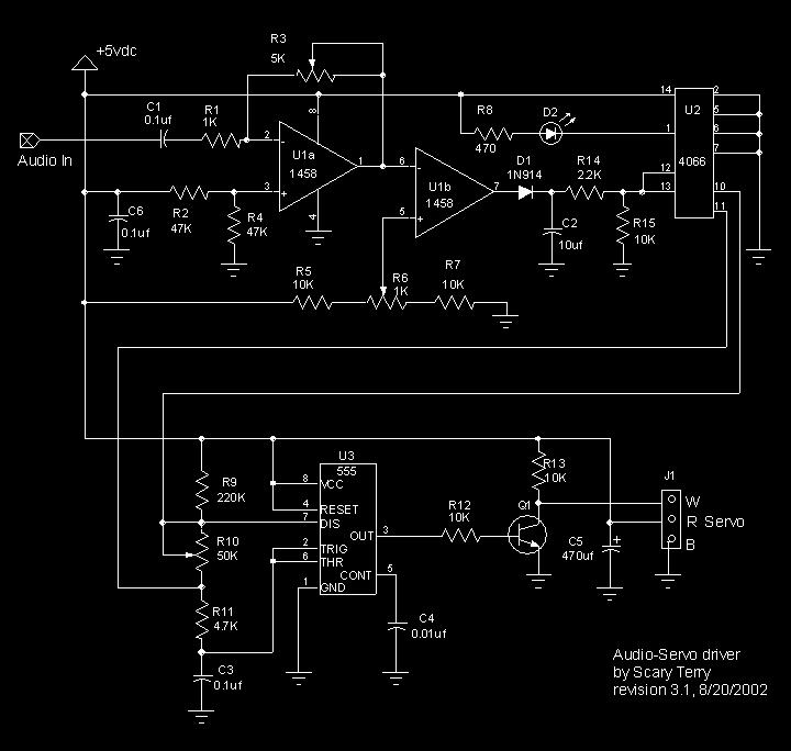
1 Audio/Servo Driver Circuit This is a circuit I've developed to drive a servo using a variety of audio sources. My goal in creating this was for a relatively simple, inexpensive and reliable circuit that doesn't require programming a microcontroller for each individual movement. I've used several of these circuits over the last several Halloweens to provide mouth movements on Bucky skulls and other animatronic heads. They have been a very reliable addition to my haunt. For audio sources I either use inexpensive CD or MP3 players or Winbond Chipcorders. Click here for a variation on the circuit that incorporates Chipcorders. Here's a web page I've put together showing how-to install a servo in a Bucky skull. As long as there is sound present, the servo will drive to its "max" position. If the sound is short in duration, the servo will not have time to drive to "max" but will drive part way and return to "min" position. While this method of moving a mouth is not perfect, it's pretty good and I'm very happy with the effect. It's important to remember that any sound will drive the servo, voice, music or noise, so if you're trying to make a Bucky mouth move to a voice track, you shouldn't have music in the background of that particular track. There is a way to include music or other sounds and still have the appropriate jaw movement. Jeff Stevens came up with a solution and I include his at the bottom of this page. First of all, if you want to do it the easy way... Cowlacious Designs offers this circuit as a kit (or completely assembled). Believe me, this is a much easier way to build this circuit than trying to do it from scratch and the kit is only a few bucks more than buying the individual parts. (Note: I am not affiliated with Cowlacious Designs. I have given them permission to use my design, but I make no money from the sale of the product).
2

3 Parts List C1 0.1 uf 50 volt capacitor R12 10k 1/4 watt resistor C2 10uf 35 volt capacitor (see text below) R13 10k 1/4 watt resistor C3 0.1 uf 50 volt capacitor R14 2.2k 1/4 watt resistor C4 0.01uf 100 volt capacitor R15 10k 1/4 watt resistor C5 470 uf 35 volt capacitor U dual op amp C6 0.1 uf 50 volt capacitor U cmos quad switch R1 1k 1/4 watt resistor U3 555 timer R2 47k 1/4 watt resistor D1 1N914 R3 5k trimmer pot D2 LED R4 47k 1/4 watt resistor Q1 2N2222 npn transistor R5 10k 1/4 watt resistor J1 3 pin male jack for servo connection R6 1k trimmer pot Two 8 pin IC sockets R7 10k 1/4 watt resistor One 14 pin IC socket R8 470 ohm 1/4 watt resistor Audio Connector (your option) R9 220k 1/4 watt resistor Power Connector (your option) R10 R11 50k trimmer pot Circuit board (it will all fit on a Radio Shack or equiv.) 4.7k 1/4 watt resistor Circuit Description From the output of your audio source, the center conductor goes to "Audio In", the outer shield goes to ground. The signal is amplified by U1a whose gain is controlled by R3. You should be able to use audio sources from a line level to a "reasonable" speaker level source and adjust the gain using R3. U1b compares the audio from U1a to a reference voltage set by R6 and sends a switched output voltage through diode D1 to CMOS switch, U2. R6 should be adjusted so that with no signal, LED D2 just turns off. Once a signal is
4 present, R6 can be used to fine tune the servo action. Capacitor C2 is used to smooth the servo operation. I show a 10uf capacitor but have used values as low as 2.2uf depending on need. Lower values make things jerky, higher values slow down the servo action. I recommend experimenting to find out what's best for your situation. You may want to consider just putting in a 0.1" spacing socket in place of C2 so it will be easy to substitute different value capacitors. That's how Cowlacious is shipping their kits now. U2 is simply used as a switch. In this case, a high on pin 12 closes a switch between pins 10 and 11, triggering the servo driver (actually, it's not a full closure but about 90 ohms of resistance). A high on pin 13 closes the switch between pins 1 and 2, which is what lights the LED. (The LED is optional, but it really makes it easier to make adjustments and insure the circuit is working correctly. If the LED is not used, pin 13 should go to ground). There are two additional switches that may be used in this IC, pin 5 controls the switch between pins 3 and 4, and pin 6 controls the switch between pins 8 and 9. The circuitry surrounding U3 is the servo driver. In its original form, the circuit was a "servo tester". I've made some modifications to make it suitable for this application. Variable resistor R10 sets the starting point of the servo, so at one extreme, the servo will start at 0 % and go all the way to 100% while at the other extreme, the servo will start at 99% and go to 100% of its travel. Capacitor C5 helps to keep the power supply stable during servo operation. J1 is the connector for the servo. This circuit, without a servo attached, only draws about 2 ma, but actively driving a servo, draws around 600 ma. I'd recommend a 5 volt power supply of at least 1 amp. I've found a good source for this type of supply is All Electronics. My favorite place to purchase servos is ServoCity. They've got good prices and I've never had any problems with their service. My current favorite standard servo is the Hitec HS-425BB. With dual ball bearings and nylon gears, it's a good compromise between performance and price. I've had a report of one guy driving seven servos off the one circuit and it worked fine. The important thing to keep in mind when driving multiple servos is that you need a power supply that will handle the combined current of the servos.
5 For reference, here are part numbers and prices for DigiKey, taken from their web site 7/2005. Part DigiKey number cost each Total C1,C3,C6 P / C2 P C4 P / C5 P R1 1.0KQBK 0.28/ R2, R4 47KQBK 0.28/ R5, R7, R12, R13, R15 10KQBK 0.28/ R8 470QBK 0.28/ R9 220KQBK 0.28/ R11 4.7KQBK 0.28/ R14 2.2KQBK 0.28/ R3 AAS53CT R6 AAS13CT R10 AAS54CT U1 LM1458NFS U2 CD4066BCN U3 LM555CNNS D1 1N914TRCT D / Q1 PN2222AFS pin ic socket ED pin ic socket ED J1 WM Circuit Board Radio Shack TOTAL As I mentioned at the beginning, the servo will respond to any sounds it's given, so if you have a voice track with music in the background, the servo will not only respond to the voice but the music as well. Jeff Stevens had a way to solve this problem and here is his to me... Dear Scary-Terry, I am writing you about a new method for using your audioservo driver. Here s how you do it. First, you record your sounds on a two channel
6 cd and player. On one of the channels have the voice and all other audio effects that you want people to hear, such as music or thunder etc. On the other channel, whether it is the left or right it doesn t matter, you record the sounds that you want to drive the audio-servo driver. You connect this channel to the audio driver. You then use a y-splitter to take the first channel, the one you want people to hear, and connect it to both channels on the amplifier or amplified speakers. You now have the ability to have music without it activating the skull. The effect sounds stereo because it is coming out of two speakers, but both are playing the same thing. That is the only disadvantage. Let me know what you think. -Jeff Stevens
Materials. Eight pin DIP socket 0.1 µf capacitor
 JOE GROELE Project Outline The goal of this project was to build a plasma speaker that will amplify an electric guitar sound. Build an audio oscillator circuit using an ordinary speaker Test speaker performance
High Current MOSFET Toggle Switch with Debounced Push Button
 Set/Reset Flip Flop This is an example of a set/reset flip flop using discrete components. When power is applied, only one of the transistors will conduct causing the other to remain off. The conducting
AMP CAMP AMP #1. Introduction. Requirements and Constraints. by Nelson Pass
 AMP CAMP AMP #1 by Nelson Pass Introduction Do-It-Yourself audio is a great activity. Many major audio components are easily constructed and made to perform as well or better than what we see in the stores
Building and Operating: Son of Zerobeat A PIC based CW zerobeat indicator from Jackson Harbor Press
 Building and Operating: Son of Zerobeat A PIC based CW zerobeat indicator from Jackson Harbor Press Ed Nisley, KE4ZNU, wrote an article published in the August, September and October of 1996 issues of
HagClock Reference Oscillator
 HAGERMAN T E C H N O L O G Y HagClock Reference Oscillator HagClock Reference Oscillator Kit Manual 2 Warnings This product uses no lethal or dangerous voltages. However, installation into a CD player
SPECIFICATIONS: Subcarrier Frequency 5.5MHz adjustable, FM Modulated +/- 50KHz. 2nd 11MHz >40dB down from 5.5MHz
 Mini-kits AUDIO / SUBCARRIER KIT EME75 Version4 SPECIFICATIONS: Subcarrier Frequency 5.5MHz adjustable, FM Modulated +/- 50KHz Subcarrier Output 1.5v p-p Output @ 5.5MHz DESCRIPTION & FEATURES: The Notes
Maintenance Manual ERICSSONZ LBI-31552E
 E Maintenance Manual TONE REMOTE CONTROL BOARD 19A704686P4 (1-Frequency Transmit Receive with Channel Guard) 19A704686P6 (4-Frequency Transmit Receive with Channel Guard) ERICSSONZ Ericsson Inc. Private
Marchand Electronics Inc.
 Marchand Electronics Inc. Rochester, NY. TEL:(585) 423 0462 www.marchandelec.com Electronic Crossover XM1 XM1 ELECTRONIC CROSSOVER NETWORK In many high performance loudspeaker systems the individual loudspeaker
picotalk OPERATING MANUAL V1.2 (May 26, 2010) 6 Oakside Court Barrie, Ontario L4N 5V5 Tel: Fax:
 6 Oakside Court Barrie, Ontario L4N 5V5 Tel: Fax:") picotalk OPERATING MANUAL V1.2 (May 26, 2010) 6 Oakside Court Barrie, Ontario L4N 5V5 Tel: 905-803-9274 Fax: 647-439-1470 www.frightideas.com Getting Familiar with your picotalk Mouth Servo Output AUX
picotalk OPERATING MANUAL V1.2 (May 26, 2010) 6 Oakside Court Barrie, Ontario L4N 5V5 Tel: 905-803-9274 Fax: 647-439-1470 www.frightideas.com Getting Familiar with your picotalk Mouth Servo Output AUX
PIR Controller IC Specification
 PIR Controller IC Specification GENERAL DESCRIPTION The IC is a CMOS chip designed to PIR controller IC. It can use PHOTO transistor or CDS application. The chip is equipped with amplifiers, comparator,
Bill of Materials: General Purpose Alarm, Pulsed PART NO
 General Purpose Alarm, Pulsed PART NO. 2190207 I hate alarms that sound continuously - unless they are smoke alarms. Smoke alarms should be annoying, but others should not. I wanted an alarm for a function
Minty Amp assembly instructions
 Minty Amp assembly instructions Parts Required: LM386 OpAmp (included in kit) 2x 100uf (min 16v) Electrolytic Capacitors (included in kit) 0.1uf Ceramic Capacitor (included in kit) 0.047uf Ceramic Capacitor
MAINTENANCE MANUAL AUDIO MATRIX BOARD P29/
 MAINTENANCE MANUAL AUDIO MATRIX BOARD P29/5000056000 TABLE OF CONTENTS Page DESCRIPTION................................................ Front Cover CIRCUIT ANALYSIS.............................................
Analyzing the Dynaco Stereo 120 Power Amplifier
 Analyzing the Dynaco Stereo 120 Power Amplifier The Stereo 120 Power Amplifier came out around 1966. It was the first powerful (60 watts per channel) solid state amplifier in wide production. Each channel
3a Switching Regulator Circuit Diagram Using Lm317
 3a Switching Regulator Circuit Diagram Using Lm317 The following circuit diagram shows a way of powering a two-way mobile radio using the The LM317T is an adjustable 3-terminal positive voltage regulator
MONO AMPLIFIER KIT ESSENTIAL INFORMATION. Version 3.0 CREATE YOUR OWN SPEAKER DOCK WITH THIS
 ESSENTIAL INFORMATION BUILD INSTRUCTIONS CHECKING YOUR PCB & FAULT-FINDING MECHANICAL DETAILS HOW THE KIT WORKS CREATE YOUR OWN SPEAKER DOCK WITH THIS MONO AMPLIFIER KIT Version 3.0 Build Instructions
First I test the resistor to make sure it doesn't fluctuate all over the place. So long as it sits stable between 506 and 560 ohms you are set.
 ENET CABLE BUILD These are my instructions for putting together an Ethernet to OBD2 cable to change features on your F-Series vehicle using E-Sys, Toolset32, ISTA P/D or other BMW programming tool. You
7 Watt Audio Amplifier with TDA2003
 7 Watt Audio Amplifier with TDA2003 Schematic diagram of a simple 7 watt audio amplifier using TDA2003 Amplifier IC. This is a good IC with many built in features like low harmonic distortion, short circuit
555 Astable Kit MitchElectronics 2018
 555 Astable Kit MitchElectronics 2018 www.mitchelectronics.co.uk CONTENTS Introduction 3 Schematic 3 How It Works 4 Materials 6 Construction 7 Important Information 8 Page 2 INTRODUCTION The 555 timer
RC Servo Interface. Figure Bipolar amplifier connected to a large DC motor
 The bipolar amplifier is well suited for controlling motors for vehicle propulsion. Figure 12-45 shows a good-sized 24VDC motor that runs nicely on 13.8V from a lead acid battery based power supply. You
CW-ADD. Universal CW Adapter for SSB Transceivers. Assembly manual. Last updated: October 1,
 CW-ADD Universal CW Adapter for SSB Transceivers Assembly manual Last updated: October 1, 2017 ea3gcy@gmail.com Updates and news at: www.ea3gcy.com Thanks for building the Universal CW Adapter kit CW-ADD
Assembly Instructions for the 1.5 Watt Amplifier Kit
 Assembly Instructions for the 1.5 Watt Amplifier Kit 1.) All of the small parts are attached to a sheet of paper indicating both their value and id. 2.) Leave the parts affixed to the paper until you are
Simple LFO Features. 2. Application. 3. Description. Simple and easy to build LFO module for Analog Synthesizers.
 Simple LFO. Simple and easy to build LFO module for Analog Synthesizers.. Features Square and Triangle waveforms (90 phase shifted) Dual range frequencies Frequency ranges from under Hz up to several khz
Brief Installation Procedure: 1. Check the Parts 2. assembly each channel in brief and make sure the assembly is correct. 3. assembly the chassis in
 Brief Installation Procedure: 1. Check the Parts 2. assembly each channel in brief and make sure the assembly is correct. 3. assembly the chassis in brief, and make sure no small parts missed. 4. fixed
Series, Parallel, and Series-Parallel Speaker Wiring
 Series, Parallel, and Series-Parallel Speaker Wiring When wiring speakers with multiple voice coils, it is important to understand the process for series and parallel wiring. Depending on what method you
Copyright 2012, R. Eckweiler & OCARC, Inc. Page 1 of 5
 Heathkit of the Month #42: by Bob Eckweiler, AF6C Heathkit HD-1422-A Antenna Noise Bridge Introduction: If you work with antennas, an antenna noise bridge can be a very handy tool. Table 1 lists some of
Building a Bitx20 Version 3
 Building a Bitx20 Version 3 The board can be broken into sections and then built and tested one section at a time. This will make troubleshooting easier as any problems will be confined to one small section.
The 6LE8 One Tube Broadcaster
 The 6LE8 One Tube Broadcaster Introduction The purpose of this broadcaster is to transmit your favorite music to every AM radio in your home. The transmitting power is so low that it should not bother
MAINTENANCE MANUAL TRANSMITTER/RECEIVER BOARD CMN-234A/B FOR MLSU141 & MLSU241 UHF MOBILE RADIO TABLE OF CONTENTS
 MAINTENANCE MANUAL TRANSMITTER/RECEIVER BOARD CMN-234A/B FOR MLSU141 & MLSU241 UHF MOBILE RADIO TABLE OF CONTENTS DESCRIPTION... 2 CIRCUIT ANALYSIS... 2 TRANSMITTER... 2 9-Voft Regulator... 2 Exciter...
S-Pixie QRP Kit. Student Manual. Revision V 1-0
 S-Pixie QRP Kit Student Manual Revision V 1-0 Introduction The Pixie 2 is a small, versatile radio transceiver that is very popular with QRP (low power) amateur radio operators the world over. It reflects
LM317T Variable Voltage Regulator
 LM317T Variable Voltage Regulator The LM317T is a adjustable 3 terminal positive voltage regulator capable of supplying in excess of 1.5 amps over an output range of 1.25 to 37 volts. The device also has
Technical Application Note #4
 CRC CACTUS Radio Club, Inc. This Technical Application Note describes the modifications that need to be incorporated into a Link Communications RLC series controller to achieve near Cactus Standard Audio
PS2-SMC-06 Servo Motor Controller Interface
 PS2-SMC-06 Servo Motor Controller Interface PS2-SMC-06 Full Board Version PS2 (Playstation 2 Controller/ Dual Shock 2) Servo Motor Controller handles 6 servos. Connect 1 to 6 Servos to Servo Ports and
Pacific Antenna Simple Keyer Kit
 Pacific Antenna Simple Keyer Kit Specifications and Features: Speed range of 5 to 30 wpm Operates in either iambic A or B mode, with B being the default 2 message memories Tune and Beacon modes Built on
Digital Output One V1.1
 Digital Output One V1.1 9/15/97-1 Digital Output One V1.1 by Erland Unruh erland.unruh@trab.se Proprietary information - Copyright (C) 1995-1997 Erland Unruh May be used freely by private persons for uncommercial
DIY Function Generator XR2206
 DIY Function Generator XR2206 20Hz 100KHz http://radiohobbystore.com Components List: Resistors: R1, R2 1% Metal Film 5K1 R4 1% Metal Film 10K R5 1% Metal Film 3K R10 5% Carbon Film 10R R3, R9 Potentiometer
Enhanced Optical Position Detector
 Enhanced Optical Position Detector Revision v0.2 January 6, 2018 Seth Neumann, seth@modelrailroadcontrolsystems.com Introduction This document describes the Morse Code Buzzer Controller and how to assemble
Threeneuron's Pile o'poo of Obsolete Crap
 Threeneuron's Pile o'poo of Obsolete Crap Home Links Nixie Stuff Dekatron Stuff Magic Eye Stuff VFD Stuff Miscellaneous Projects Nixie Thermometer Kit Available at my ebay Store (Click on Photo to view
The Tellun Corporation. TLN-863 Max Min Generator. User Guide, Rev Scott Juskiw The Tellun Corporation
 The Tellun Corporation TLN-863 Max Min Generator User Guide, Rev. 1.1 Scott Juskiw The Tellun Corporation scott@tellun.com TLN-863 User Guide Revision 1.1 May 26, 2008 1. Introduction The TLN-863 Max Min
Low Voltage, High Current Time Delay Circuit
 Low Voltage, High Current Time Delay Circuit In this circuit a LM339 quad voltage comparator is used to generate a time delay and control a high current output at low voltage. Approximatey 5 amps of current
30 Watt Audio Power Amplifier
 30 Watt Audio Power Amplifier Including Preamp, Tone Controls, Reg dc Power Supply, 18 Watt into 8 Ohm - 30W into 4 Ohm loads Amplifier Section Circuit diagram: Audio Power Amplifier Circuit Diagram This
10 2 2,13,15,16,46 27, non-inductive ,26,
 HANDS-ON RADIO PARTS LIST (Thanks, John AF4WM and Steve AD7KR) Updated through Experiment 129 Quantities assume all parts available for re-use MAX QTY EXPERIMENT NOTES 1/4 WATT RESISTOR (All values are
The Tellun Corporation. TLN-861 Dunsel. User Guide, Rev Scott Juskiw The Tellun Corporation
 The Tellun Corporation TLN-861 Dunsel User Guide, Rev. 1.0 Scott Juskiw The Tellun Corporation scott@tellun.com TLN-861 User Guide Revision 1.0 August 31, 2006 1. Introduction The TLN-861 Dunsel is a collection
NOTE: The relay coil is polarity sensitive
 External QSK T/R Switch for HF Amplifiers Phil Salas AD5X Like many HF amplifiers, my Ameritron ALS-600 uses a power relay for T/R switching. The long 15-20ms enable/release time of this relay makes the
Step by Step Building PJ meter ARDF Receiver Kit. CRKITS.COM August 5, 2013
 Step by Step Building PJ-80 80-meter ARDF Receiver Kit CRKITS.COM August 5, 2013 What is ARDF? ARDF is the abbreviation of Amateur Radio Direction Finding, or so called Fox Hunting. If you are looking
5U Oakley Modular Series. Dual Comparator and Gate Delay CV and Audio Processor
 Oakley Sound Systems 5U Oakley Modular Series Dual Comparator and Gate Delay CV and Audio Processor PCB Issue 2 Builder s Guide V2.1 Tony Allgood Oakley Sound Systems CARLISLE United Kingdom The suggested
Kanga US 3521 Spring Lake Dr. Findlay, OH
 Kanga US 3521 Spring Lake Dr. Findlay, OH 45840 419-423-4604 kanga@kangaus.com www.kangaus.com minir2 Construction Notes Components (except for surface mount components) are mounted on the side of the
Building and Operating: LF Converter An SA612 based LF up-converter from Jackson Harbor Press
 Introduction: Building and Operating: LF Converter An SA612 based LF up-converter from Jackson Harbor Press The frequencies below the broadcast band are covered by few receivers on the market - those that
AAØZZ Control Board for Si570 Daughtercard
 AAØZZ Control Board for Si570 Daughtercard Complete Signal Generator for 10 to 157 MHz By Craig Johnson, AAØZZ AAØZZ@CBJOHN.COM www.cbjohn.com/aaøzz TABLE OF CONTENTS 1 Introduction... 2 2 Hardware Description...
What is the Kicker F.I.T. input circuit and why is it better?
 What is the Kicker F.I.T. input circuit and why is it better? F.I.T. input: Kicker uses a special circuit for the audio input to our amplifiers called Failsafe Integration Technology or (F.I.T.) for short.
Maintenance Manual TRANSMITTER/RECEIVER BOARD CMN-233 FOR MLSH041
 Maintenance Manual TRANSMITTER/RECEIVER BOARD CMN-233 FOR MLSH041 TABLE OF CONTENTS Page DESCRIPTION... 2 CIRCUIT ANALYSIS... 2 Transmitter... 2 9-volt Regulator... 2 Exciter... 2 40-Watt PA... 2 Antenna
BMC011. Wave Animator Written April 8, 2013 Last Editted April 8, 2013
 BMC011. Wave Animator Written April 8, 2013 Last Editted April 8, 2013 I. What is a Wave Animator?/Demos II. Circuit Description/Schematics III. Construction A. Parts List B. PCB Information I.What Is
ALX-SSB 5 Band Filter Assembly Manual 19 November 2018
 ALX-SSB 5 Band Filter Assembly Manual 19 November 2018 Contents Theory of Operation:... 1 Figure 1... 2 Parts Included:... 4 Board Overview:... 5 Figure 2... 5 Figure 3... 5 Board Assembly:... 6 Cable
Handy dandy little circuit #17 #17
 Handy dandy little circuit #17 #17 Download # 17 in PDF There are a lot of alarm systems on the market but you might be inclined to build your own. This little project can be put together using inexpensive
How to build a Cracklebox. Red Wierenga Brooklyn College Center for Computer Music October 13, 2015
 How to build a Cracklebox Red Wierenga Brooklyn College Center for Computer Music October 13, 2015 What s a Cracklebox? What s a Cracklebox? The Cracklebox was developed by Michel Waisvisz and others at
K44 Audio Splitter Board Kit
 Introduction The K44 has a great CW reader but one thing that slows most folks down is connecting audio from their receiver to the K44's audio input. recommends using audio from the receiver's audio line
I'm guessing this is what has made it so no one else could get the circuit to work, I hope this helps.
 Incase I did not mention this else where, the basis of my system to provide random audio bits which the spirits can use to form their voices. The audio bits are from randomly tuning a voltage tunable AM
AVL-10000T AUDIO VIDEO LINK TRANSMITTER TECHNICAL MANUAL
 AVL-10000T AUDIO VIDEO LINK TRANSMITTER TECHNICAL MANUAL Document : AVL-10000T Version: 1.00 Author: Henry S Date: 25 July 2008 This module contains protection circuitry to guard against damage due to
Introduction to Electronics and Breadboarding Circuits
 Introduction to Electronics and Breadboarding Circuits What we're going to learn today: What is an electronic circuit? What kind of power is needed for these projects? What are the fundamental principles
TV Remote. Discover Engineering. Youth Handouts
 Discover Engineering Youth Handouts Electronic Component Guide Component Symbol Notes Amplifier chip 1 8 2 7 3 6 4 5 Capacitor LED The amplifier chip (labeled LM 386) has 8 legs, or pins. Each pin connects
N3ZI Kits General Coverage Receiver, Assembly & Operations Manual (For Jun 2011 PCB ) Version 3.33, Jan 2012
 Version 3.33, Jan 2012") N3ZI Kits General Coverage Receiver, Assembly & Operations Manual (For Jun 2011 PCB ) Version 3.33, Jan 2012 Thank you for purchasing my general coverage receiver kit. You can use the photo above as a
N3ZI Kits General Coverage Receiver, Assembly & Operations Manual (For Jun 2011 PCB ) Version 3.33, Jan 2012 Thank you for purchasing my general coverage receiver kit. You can use the photo above as a
List of Items Available in the Laboratory the Lab
 List of Items Available in the Laboratory the Lab Category Component 555 Timer $0.30 5V Relay $3.50 74xxx Series IC Chip $0.30 Battery - 12V (rechargeable Lead-acid type) $16.00 Battery - 6V (rechargeable
An Electronic Variable Load by Dave Chute, KG4BZW
 EDITOR: GEOFF HAINES, N1GY Published Quarterly N1GY@ARRL.NET Summer Edition FROM THE EDITOR: Once again I am happy to report that we have several great articles in the Summer Edition of The WCF Experimenter.
The list below is sufficient for the initial set-up of a single baseline (2 dish) VSRT interferometer. VSRT parts:
 VSRT interferometer. VSRT parts:") VSRT MEMO #047 MASSACHUSETTS INSTITUTE OF TECHNOLOGY HAYSTACK OBSERVATORY WESTFORD, MASSACHUSETTS 01886 May 4, 2010 Telephone: 781-981-5407 Fax: 781-981-0590 To: VSRT Group From: Alan E.E. Rogers and Preethi
VSRT MEMO #047 MASSACHUSETTS INSTITUTE OF TECHNOLOGY HAYSTACK OBSERVATORY WESTFORD, MASSACHUSETTS 01886 May 4, 2010 Telephone: 781-981-5407 Fax: 781-981-0590 To: VSRT Group From: Alan E.E. Rogers and Preethi
Harris IRT Enterprises Multi-Channel Digital Resistance Tester Model XR
 Harris IRT Enterprises Multi-Channel Digital Resistance Tester Model 6012-06XR Specifications & Dimensions 2 Theory of Operation 3 System Block Diagram 4 Operator Controls & Connectors 5 Test Connections
BassAce - Midi Bass Synthesizer. BassAce Features
 Untitled Document BassAce - Midi Bass Synthesizer The BassAce is a small midi-synth based loosely on the TB303. It can be built many different ways. Depending on how it's configured it can be anything
Guardian Telecom Inc Fisher Road S.E., Calgary, Alberta, Canada T2H 0W3 Voice Fax
 Guardian Telecom Inc. 7000 Fisher Road S.E., Calgary, Alberta, Canada T2H 0W3 Voice 403-258-3100 Fax 403-253-4967 SERVICE MANUAL AS-DA16 AUDIO DISTRIBUTION AMPLIFIER GENERAL DESCRIPTION: An AS-DA16 Audio
FM Audio/Squelch Board by Steve Dold, W6KCS w6kcs (at) stevedold (dot) com
 stevedold (dot) com") FM Audio/Squelch Board by Steve Dold, W6KCS w6kcs at stevedold dot com Board hardware version 7-8 Firmware version 7.x This board connects to an FM receiver's discriminator/detector and provides squelched,
FM Audio/Squelch Board by Steve Dold, W6KCS w6kcs at stevedold dot com Board hardware version 7-8 Firmware version 7.x This board connects to an FM receiver's discriminator/detector and provides squelched,
Penrose Quantizer Assembly Guide
 Penrose Quantizer Assembly Guide Schematic and BOM The schematic can be found here: www.sonic-potions.com/public/penrosequantizerschematic.pdf The BOM is available at google docs: Link to BOM Prepare the
Building The DC Beeper from Jackson Harbor Press A Morse code voltmeter / DC switch
 Building The DC Beeper and from Jackson Harbor Press Operating A Morse code voltmeter / DC switch The DC Beeper kit is a combination of a Morse code voltmeter with 20 mv resolution and a DC switch. The
The Aleph 5 is a stereo 60 watt audio power amplifier which operates in single-ended class A mode.
 Pass Laboratories Aleph 5 Service Manual Rev 0 9/20/96 Aleph 5 Service Manual. The Aleph 5 is a stereo 60 watt audio power amplifier which operates in single-ended class A mode. The Aleph 5 has only two
Project 1 Final System Design and Performance Report. Class D Amplifier
 Taylor Murphy & Remo Panella EE 333 12/12/18 Project 1 Final System Design and Performance Report Class D Amplifier Intro For this project, we designed a class D amplifier circuit. Class D amplifiers work
ELECTRIC GENERAL. MAINTENANCE MANUAL MHz, 35 WATT POWER AMPLIFIER ASSEMBLY 19D430488G1, 2 DESCRIPTION CIRCUIT ANALYSIS
 MAINTENANCE MANUAL 851-870 MHz, 35 WATT POWER AMPLIFIER ASSEMBLY 19D430488G1, 2 DESCRIPTION The power amplifier assembly for MASTR II uses six RF power transistors to provide a maximum of 35 Watts output
Opamp Based Power Amplifier
 Introduction Opamp Based Power Amplifier Rohit Balkishan This is a contributed project from Rohit Balkishan, who has built it, and thought that it would make a nice simple project for others. This is a
Wiring Manual NEScaf April 2010 (August 2006)
") Wiring Manual NEScaf April 2010 (August 2006) Switched Capacitor Audio Filter The NEScaf is a switched capacitor audio filter (acronym SCAF) built around a building-block type filter chip. The NEScaf will
Wiring Manual NEScaf April 2010 (August 2006) Switched Capacitor Audio Filter The NEScaf is a switched capacitor audio filter (acronym SCAF) built around a building-block type filter chip. The NEScaf will
Introduction 1. Download socket (the cable plugs in here so that the GENIE microcontroller can talk to the computer)
") Introduction 1 Welcome to the magical world of GENIE! The project board is ideal when you want to add intelligence to other design or electronics projects. Simply wire up your inputs and outputs and away
Introduction 1 Welcome to the magical world of GENIE! The project board is ideal when you want to add intelligence to other design or electronics projects. Simply wire up your inputs and outputs and away
Review: The Ameritron RCS-12C Controller and RCS-10/12 Remote Relay Box Phil Salas AD5X
 Review: The Ameritron RCS-C Controller and RCS-0/ Remote Relay Box Phil Salas ADX Introduction Automatic band decoders read your transceiver s band data or frequency information and output DC control voltages
First read the summary. Otherwise, you might find it confusing. There are 2 types of voice to skull:
 Electronics behind V2K First read the summary. Otherwise, you might find it confusing. There are 2 types of voice to skull: 1. The pulsed microwave method: every time the voice wave goes from positive
SE4 DSP + High Performance Professional Digital Stereo Encoder With DSP Filters
 PCS Electronics www.pcs-electronics.com info@pcs-electronics.com SE4 DSP + High Performance Professional Digital Stereo Encoder With DSP Filters SE4 DSP + without the LCD control module (connects to black
Final Project Stereo Audio Amplifier Final Report
 The George Washington University School of Engineering and Applied Science Department of Electrical and Computer Engineering Final Project Stereo Audio Amplifier Final Report Daniel S. Boucher ECE 20-32,
CMU232 User Manual Last Revised October 21, 2002
 CMU232 User Manual Last Revised October 21, 2002 Overview CMU232 is a new low-cost, low-power serial smart switch for serial data communications. It is intended for use by hobbyists to control multiple
D ELCO. electronic parts AUTO RADIO BULLETIN. Connect Signal Generator to
 D ELCO electronic parts AUTO RADIO BULLETIN Bulletin 6D-864 Date 10-15-56 Page 1 FIRST ISSUE SUBJECT: SERVICE INSTRUCTIONS - CHEVROLET CUSTOM DELUXE WITH PUSH BUTTON TUNING - MODEL 987575 GENERAL M O U
D-VERB Digital Reverb Unit
 This is the D-VERB (Digital Reverb) kit. It is an excellent sounding reverb pedal, simple to build and compact for the pedal board. The source of the reverb sound is a digital reverb module made called
Main improvements are increased number of LEDs and therefore better temperature indication with one Celsius degree increments.
 LED Thermometer V2 (Fahrenheit/Celsius/±1 ) PART NO. 2244754 After completing this great starter kit, users will have a nice interactive LED thermometer. You will learn one principle how temperature can
SoftRock v5.0 Builder s Notes. December 12, Building a QSD Kit
 SoftRock v5.0 Builder s Notes December 12, 2005 Building a QSD Kit Be sure to use a grounded tip soldering iron in building the QSD board. The soldering iron needs to have a small tip, (0.05-0.1 inch diameter),
Amplifier, Product Design
 Amplifier, Product Design Choose one component from the amplifier circuit and investigate technical, theory and mathematical information related to your chosen component. This work will be completed over
MAINTENANCE MANUAL AUDIO BOARDS 19D902188G1, G2 & G3
 B MAINTENANCE MANUAL AUDIO BOARDS 19D902188G1, G2 & G3 TABLE OF CONTENTS Page Front Cover DESCRIPTION............................................... CIRCUIT ANALYSIS............................................
Beta-test ED1 PCB installed in I0CG s K1
 K1 SSB Modification (Ed.2) This description provides the receiver (RX) modifications, assembly, alignment and operation as a first step. In a second step you can add the remaining transmitter (TX) modifications,
Techniques for Passive Circuit Analysis for. State Space Differential Equations
 Techniques for Passive Circuit Analysis for chp4 1 State Space Differential Equations 1. Draw circuit schematic and label components (e.g., R 1, R 2, C 1, L 1 ) 2. Assign voltage at each node (e.g., e
27 November 01 RST-504 DOCUMENT SUMMARY Chassis Schematic (with intercom) Aircraft Electrical Installation
 Aircraft Electrical Installation") RST ENGINEERING MAIL: 13249 Grass Valley Ave SHIP: 13993 Downwind Court Grass Valley CA 95945 Voice (916) 272-2203 E-mail: sales@rst-engr.com Web Page: http://www.rst-engr.com 27 November 01 RST-504 DOCUMENT
RST ENGINEERING MAIL: 13249 Grass Valley Ave SHIP: 13993 Downwind Court Grass Valley CA 95945 Voice (916) 272-2203 E-mail: sales@rst-engr.com Web Page: http://www.rst-engr.com 27 November 01 RST-504 DOCUMENT
6. HARDWARE PROTOTYPE AND EXPERIMENTAL RESULTS
 6. HARDWARE PROTOTYPE AND EXPERIMENTAL RESULTS Laboratory based hardware prototype is developed for the z-source inverter based conversion set up in line with control system designed, simulated and discussed
Adjustable Parametric Equalizer Hardware Description
 Adjustable Parametric Equalizer Hardware Description Adam Grunke April 27, 2004 ETEC 474 Professor Morton Introduction The Adjustable Parametric Equalizer (APE) allows the professional audio engineer to
The ROSE 80 CW Transceiver (Part 1 of 3)
") Build a 5 watt, 80 meter QRP CW Transceiver!!! Page 1 of 10 The ROSE 80 CW Transceiver (Part 1 of 3) Build a 5 watt, 80 meter QRP CW Transceiver!!! (Designed by N1HFX) A great deal of interest has been
Build a 5 watt, 80 meter QRP CW Transceiver!!! Page 1 of 10 The ROSE 80 CW Transceiver (Part 1 of 3) Build a 5 watt, 80 meter QRP CW Transceiver!!! (Designed by N1HFX) A great deal of interest has been
ICOM R10 Receiver Modification to Provide S-Meter Output
 ICOM R10 Receiver Modification to Provide S-Meter Output A Technical Application Note from Doppler Systems Inc. Acknowledgements April 21, 2001 Revised June 6, 2004 This application note was submitted
MANUAL UPDATING CHANGES CHANGE DATE: June 16, 2004
 MANUAL UPDATING CHANGES CHANGE DATE: June 16, 2004 MANUAL IDENTIFICATION MANUAL UPDATING COVERAGE This supplement adapts your manual to Serial Numbers prefixed through: 3708A Instrument: HP 5087A Distribution
Electronic Instrumentation ENGR-4300 Fall 2002 Project 2: Optical Communications Link
 Project 2: Optical Communications Link For this project, each group will build a transmitter circuit and a receiver circuit. It is suggested that 1 or 2 students build and test the individual components
El-Cheapo - A Really Simple Power Amplifier
 El-Cheapo - A Really Simple Power Amplifier Rod Elliott - ESP (Semi-Original Design) "Semi-Original Design" - What is that supposed to mean? Well, many years ago, there was an amplifier circuit in a magazine
Figure 2 shows the actual schematic for the power supply and one channel.
 Pass Laboratories Aleph 3 Service Manual rev 0 2/1/96 Aleph 3 Service Manual. The Aleph 3 is a stereo 30 watt per channel audio power amplifier which operates in single-ended class A mode. The Aleph 3
6V to 12V dc-dc boost converter using 555 timer IC
 6V to 12V dc-dc boost converter using 555 timer IC dc-dc converter schematic This 6V to 12V dc-dc boost converter can drive a load in 12V about 1.5A current.the 555 timer IC is operated in astable mode,
EE283 Electrical Measurement Laboratory Laboratory Exercise #7: Digital Counter
 EE283 Electrical Measurement Laboratory Laboratory Exercise #7: al Counter Objectives: 1. To familiarize students with sequential digital circuits. 2. To show how digital devices can be used for measurement