Project 1 Final System Design and Performance Report. Class D Amplifier
|
|
|
- Rosalyn Hudson
- 5 years ago
- Views:
Transcription
1 Taylor Murphy & Remo Panella EE /12/18 Project 1 Final System Design and Performance Report Class D Amplifier Intro For this project, we designed a class D amplifier circuit. Class D amplifiers work by passing the input signal through a comparator with a triangle wave. This then generates a pulse width modulated wave that is then passed through a transistor switching stage. In this switching stage, the transistors are sized so that only one is on at a time, therefore improving the efficiency of the amplifier. This signal is then passed through a low pass filter to obtain the amplified output. We initially wanted to construct the circuit using only discrete parts, but were informed the switching stage is very difficult to design. Instead, we opted to use a class D chip to simplify the circuit. The main component of the circuit is the TPA3125D2, a Texas Instruments Class D amplifier chip. The circuit is powered by a wall transformer and drives stereo speakers. There is a mute and shutdown function that is implemented through switches. There is also gain control with four different gain settings which are 20, 26, 32, and 36 db. This report will break down the design and performance of our circuit.


2 Circuit Schematic Schematic Details Power Supply: The circuit is powered off a 16.5 VAC wall transformer. This is then passed through a full wave rectifier and smoothing capacitors and then an 18 V linear regulator. This 18 volts provides power to the left and right channels of the chip. It also is used with the mute, shutdown, and gain switches.


3 Mute and Shutdown: The Mute function is enabled when the switch is closed, connecting the mute pin to the voltage supply. The Shutdown function is enabled when the switch is closed, connecting the shutdown pin to ground. Gain: The gain if the circuit is controlled by two switches. Closing the switches increases the gain by connecting the respective gain pins to the voltage supply. The gain settings are 20, 26, 32, and 36 db. Output Filter: There are two output filters in this circuit, one for each channel. This is a low pass LC filter mainly consisting of a 33 uh inductor and a 0.22 uf capacitor. There are also resistors to bleed charge off the capacitors once the circuit is shutdown.

4 Design Details The main focus of this design was behind powering the chip and filtering the output. The power supply for the chip is 18 V. We obtain this by using a 16.5 VAC wall transformer. This is then passed through a full wave rectifier and smoothing capacitors. This is then passed through a 18 V linear regulator that then powers the chip. The output filter of this circuit is based on recommendations for the chip and output configuration we are using. Since we are using a single ended stereo output, Texas Instruments recommends an output filter of a 33 uh inductor and a 0.22 uf capacitor. This provides a cutoff frequency of around Hz. Below is the pin diagram for the chip. Pins 1 and 10 are the power supply for the left and right channel switching stages. They are connected to the 18 V linear regulator with bypass capacitors. This is an attempt to remove the hum from the power supply so it can t be heard at the output. Pins 2 and 3 are the
5 shutdown and mute pins and they are connected to switches. These switches allow these pins to be connected to ground or the power supply to provide logic low and high. Pins 4 and 5 are the left and right inputs and are connected to the input through input capacitors. These are recommended by Texas Instruments to improve the low frequency response of the circuit. Pin 6 is the bypass pin and it is connected to ground through a capacitor. The size of this capacitor affects the startup time of the amplifier. With a 1 uf capacitor, start up time is around 500 ms. Pins 7 and 8 are analog grounds that are connected straight to ground. Pin 9 is connected through a capacitor to ground. This 1 uf capacitor is required as it allows an internal regulator to clamp the gate voltage for the output transistors. Pins 11 and 20 are the power ground for the switching stage of the left and right channels. These pins are connected to ground. Pins 12 and 19 are the output for the left and right channel. This output is in the form of a pulse width modulated wave. This wave is then passed through our low pass filter to obtain the final output. Pins 13 and 18 are connected to the left and right outputs through bootstrap capacitors. These bootstrap capacitors are required to allow the switching stages to turn on correctly. Pins 14 and 15 control the gain of the amplifier. They are connected to switches that either connect them to ground, or the power supply. This allows us to vary the gain to four different settings, 20, 26, 32, and 36 db. Pins 16 and 17 are analog voltage pins. These are connected to our power supply and these pins provide power to the comparators inside the chip. Performance Details

6 In order to observe the performance of the circuit, we first tested it with sine waves from a signal generator. We tested with an input signal with a peak to peak voltage of 220 mv. At the left and right outputs of the chip before the filter, we observed the pulse width modulated waveform. There is some aliasing in this waveform when the output goes from low to high. Below is an image of the output before the filter. We then observed the output after the filter. We used a 2 khz, 220 mv peak to peak sine wave as the input. We looked at the output under our 4 gain settings, 20, 26, 32, and 36 db. In these outputs, we don t see a perfect reconstruction of the sine wave. The filter doesn t seem to perfectly filter out the high frequency pulse width modulated waveform, so the output looks like a sine wave modulated with the pulse width modulated waveform. This filter doesn t distort the frequency of the output signal. Below are the images of the output signals for the various gains.

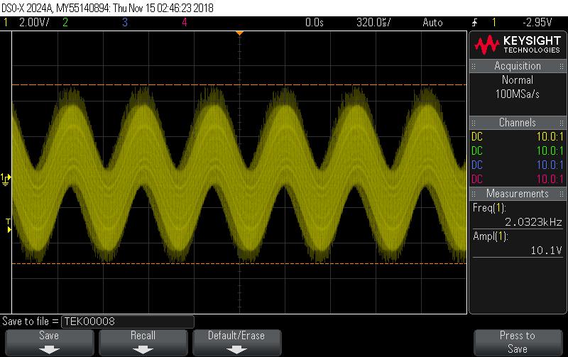
7 Gain: 20 db

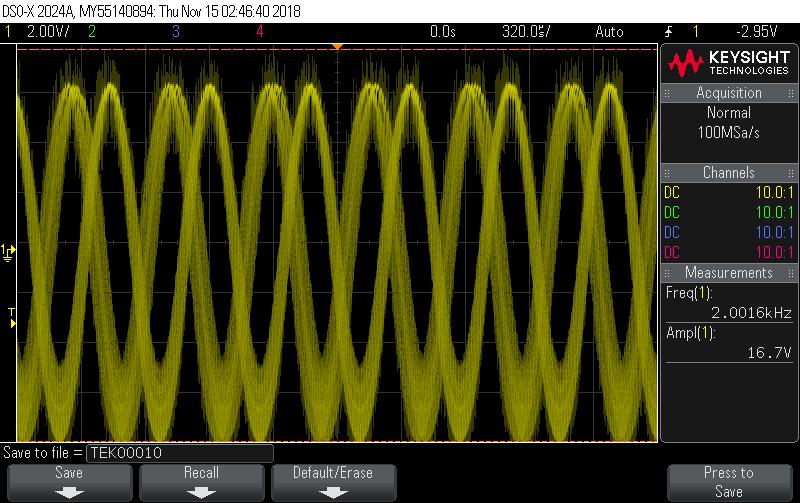
8 Gain: 26 db Gain: 32 db

9 Gain: 36 db On the highest gain setting, we begin to observe clipping. We start to approach an amplitude close to 18 V, which is our power supply voltage. This causes clipping and distortion. Below is an image on the highest gain setting where the clipping is more evident. You can see at the top of the waveform how it is beginning to be distorted. Although the output looks quite distorted, when testing the circuit with music instead of a sine wave. The output when testing with music is not distorted and sounds fine. Video of our circuit testing with music can be found in presentation 2 on the documents page of the course website. We also tested the circuits mute and shutdown capabilities. The mute effectively turns off the left and right output channels so nothing can be heard. The shutdown feature also works well and puts the chip into a low power state. It is important to use the shutdown

10 feature when powering the circuit. We found that starting the chip in shutdown mode, then applying the input audio signal, then turning off shutdown mode reduced popping and allowed for a better startup. We measured the input and output power in order to see how efficient our circuit was. We found the input power to be 6.75 W and the output power to be 2.67 W per channel. This leads us to an efficiency of around 80%. Overall, the circuit works well and is capable of playing music quite loud. Below is an image of the final prototype. Conclusion This circuit we designed operates as a decently efficient class D amplifier. We ran into a couple different issues when prototyping the circuit. We initially had a 24 VAC wall transformer
11 and a 24 V linear regulator in our power supply stage. This led to issues with the linear regulator because we were trying to drop the voltage from 34 V to 24 V. This led to a lot of heat being dissipated in the regulator. By switching to a 16.5 VAC wall transformer and a 18 V linear regulator, this heat problem was solved. We also had a hum problem when testing the circuit with speakers. The hum wasn t incredibly loud, but if your head was maybe 1 foot from the speaker, then you could hear the hum. This issue was being caused by a ground loop. By properly grounding the circuit, the hum was reduced. There is still a slight hum present, but this is caused by the 120 V, 60 Hz signal going into the wall transformer. We recently found an effective way to almost entirely remove the hum. We increased the capacitance in our power stage and properly grounded the audio inputs through 3.3 kohm resistors (These changes can be seen in the above image. large 2700 uf capacitors in the upper left, resistors from audio input to ground in bottom right). This made the hum much less noticeable. There is also the issue of the distortion from the pulse width modulated wave. We spent quite a bit of time trying to figure out how to remove this distortion. We tried various different filter components to adjust the corner frequency and remove the distortion. This slightly remedied it but the distortion was still there when testing with the signal generator. Once we tested it with speakers and an actual audio input and realized that it wasn t distorting the output, we just assumed it was how the class D chip was meant to operate. Overall, the circuit performed as desired and is a pretty cool audio device.
Project 2 Final System Design and Performance Report. Triple Output Power Supply
 Taylor Murphy & Remo Panella EE 333 12/12/18 Project 2 Final System Design and Performance Report Triple Output Power Supply Intro For this project, we designed a triple output power supply using switch
Final Project Stereo Audio Amplifier Final Report
 The George Washington University School of Engineering and Applied Science Department of Electrical and Computer Engineering Final Project Stereo Audio Amplifier Final Report Daniel S. Boucher ECE 20-32,
University of North Carolina, Charlotte Department of Electrical and Computer Engineering ECGR 3157 EE Design II Fall 2009
 University of North Carolina, Charlotte Department of Electrical and Computer Engineering ECGR 3157 EE Design II Fall 2009 Lab 1 Power Amplifier Circuits Issued August 25, 2009 Due: September 11, 2009
11. Audio Amp. LM386 Low Power Amplifier:
 EECE208 INTRO TO EE LAB Dr. Charles Kim 11. Audio Amp Objectives: The main purpose of this laboratory exercise is to design an audio amplifier based on the LM386 Low Voltage Audio Power Amplifier chip
Low Cost Screening Audiometer
 Abstract EE 389 EDL Report, EE Dept. IIT Bombay, submitted on Nov.2004 Low Cost Screening Audiometer Group No.: D3 Chirag Jain 01d07018 Prashant Yadav 01d07024 Puneet Parakh 01d07007 Supervisor: Prof.
Lab 4: Analysis of the Stereo Amplifier
 ECE 212 Spring 2010 Circuit Analysis II Names: Lab 4: Analysis of the Stereo Amplifier Objectives In this lab exercise you will use the power supply to power the stereo amplifier built in the previous
University of Utah Electrical Engineering Department ECE 2100 Experiment No. 2 Linear Operational Amplifier Circuits II
 University of Utah Electrical Engineering Department ECE 2100 Experiment No. 2 Linear Operational Amplifier Circuits II Minimum required points = 51 Grade base, 100% = 85 points Recommend parts should
Week 8 AM Modulation and the AM Receiver
 Week 8 AM Modulation and the AM Receiver The concept of modulation and radio transmission is introduced. An AM receiver is studied and the constructed on the prototyping board. The operation of the AM
Figure 2 shows the actual schematic for the power supply and one channel.
 Pass Laboratories Aleph 3 Service Manual rev 0 2/1/96 Aleph 3 Service Manual. The Aleph 3 is a stereo 30 watt per channel audio power amplifier which operates in single-ended class A mode. The Aleph 3
Lauren Gresko, Elliott Williams, Elaine McVay Final Project Proposal 9. April Analog Synthesizer. Motivation
 Lauren Gresko, Elliott Williams, Elaine McVay 6.101 Final Project Proposal 9. April 2014 Motivation Analog Synthesizer From the birth of popular music, with the invention of the phonograph, to the increased
The Aleph 5 is a stereo 60 watt audio power amplifier which operates in single-ended class A mode.
 Pass Laboratories Aleph 5 Service Manual Rev 0 9/20/96 Aleph 5 Service Manual. The Aleph 5 is a stereo 60 watt audio power amplifier which operates in single-ended class A mode. The Aleph 5 has only two
Capacitive Touch Sensing Tone Generator. Corey Cleveland and Eric Ponce
 Capacitive Touch Sensing Tone Generator Corey Cleveland and Eric Ponce Table of Contents Introduction Capacitive Sensing Overview Reference Oscillator Capacitive Grid Phase Detector Signal Transformer
Power Supply Considerations for DDX Amplifiers
 Power Supply Considerations for DDX Amplifiers For Applications Assistance Contact: Ken Korzeniowski Apogee Technology, Inc. 19 Morgan Drive Norwood, MA 006, USA kkorz@apogeeddx.com 781-551-9450 Last Updated
Analyzing the Dynaco Stereo 120 Power Amplifier
 Analyzing the Dynaco Stereo 120 Power Amplifier The Stereo 120 Power Amplifier came out around 1966. It was the first powerful (60 watts per channel) solid state amplifier in wide production. Each channel
Electronic Circuits EE359A Final project requirements
 Design an electronic circuit it may be one of the ideas described below or a similar project of your choosing. Senior Design projects are acceptable designs if the design is yours, and not your team s.
University of North Carolina-Charlotte Department of Electrical and Computer Engineering ECGR 3157 Electrical Engineering Design II Fall 2013
 Exercise 1: PWM Modulator University of North Carolina-Charlotte Department of Electrical and Computer Engineering ECGR 3157 Electrical Engineering Design II Fall 2013 Lab 3: Power-System Components and
Dual preamplifier with ALC
 Dual preamplifier with ALC The BA3308, BA3308F and BA3308FV are dual preamplifier ICs with built-in ALC circuits, and have been designed for use in stereo radio-cassette recorders and tape recorders. They
The Aleph 2 is a monoblock 100 watt audio power amplifier which operates in single-ended class A mode.
 Pass Laboratories Aleph 2 Service Manual Rev 0 2/1/96 Aleph 2 Service Manual. The Aleph 2 is a monoblock 100 watt audio power amplifier which operates in single-ended class A mode. The Aleph 2 has only
Electronic Instrumentation ENGR-4300 Fall Project 4: Optical Communications Link
 Project 4: Optical Communications Link In this project you will build a transmitter and a receiver circuit. The transmitter circuit uses pulse frequency modulation to create a series of light pulses that
EXPERIMENT 4 LIMITER AND CLAMPER CIRCUITS
 EXPERIMENT 4 LIMITER AND CLAMPER CIRCUITS 1. OBJECTIVES 1.1 To demonstrate the operation of a diode limiter. 1.2 To demonstrate the operation of a diode clamper. 2. INTRODUCTION PART A: Limiter Circuit
3 Circuit Theory. 3.2 Balanced Gain Stage (BGS) Input to the amplifier is balanced. The shield is isolated
 Input to the amplifier is balanced. The shield is isolated") Rev. D CE Series Power Amplifier Service Manual 3 Circuit Theory 3.0 Overview This section of the manual explains the general operation of the CE power amplifier. Topics covered include Front End Operation,
Rev. D CE Series Power Amplifier Service Manual 3 Circuit Theory 3.0 Overview This section of the manual explains the general operation of the CE power amplifier. Topics covered include Front End Operation,
DEPARTMENT OF ELECTRICAL ENGINEERING AND COMPUTER SCIENCE MASSACHUSETTS INSTITUTE OF TECHNOLOGY CAMBRIDGE, MASSACHUSETTS 02139
 DEPARTMENT OF ELECTRICAL ENGINEERING AND COMPUTER SCIENCE MASSACHUSETTS INSTITUTE OF TECHNOLOGY CAMBRIDGE, MASSACHUSETTS 019.101 Introductory Analog Electronics Laboratory Laboratory No. READING ASSIGNMENT
Class D audio-power amplifiers: Interactive simulations assess device and filter performance
 designfeature By Duncan McDonald, Transim Technology Corp CLASS D AMPLIFIERS ARE MUCH MORE EFFICIENT THAN OTHER CLASSICAL AMPLIFIERS, BUT THEIR HIGH EFFICIENCY COMES AT THE EXPENSE OF INCREASED NOISE AND
St. Marks Arrays. <coeff sets 1 & 2, excel doc w/ steering values, array program, > 1. System Setup Wiring & Connection diagram...
 St. Marks Arrays Contents 0. Included Documents: 1. System Setup......... 2 1.1 Wiring & Connection diagram..... 2 1.2 Optimum Equipment
Lab 6: Building a Function Generator
 ECE 212 Spring 2010 Circuit Analysis II Names: Lab 6: Building a Function Generator Objectives In this lab exercise you will build a function generator capable of generating square, triangle, and sine
Screening Audiometer
 EE89 Electronic Design Lab (EDL) Report, EE Dept, IIT Bombay, December, 00 Screening Audiometer Group No. D0 Mahim Agrawal (0D000) < mahim@ee.iitb.ac.in > Ashok Kumar Bhardwaj (0D00) < ashokkb@ee.iitb.ac.in
15V Stereo Class-D Audio Power Amplifier. Description. Tracking Code Date Code
 15V Stereo Class-D Audio Power Amplifier Features Operate from 8~15V supply voltage Class-D power 15W/ch into 8Ω from 15V supply @ 10% THD+N for stereo 12W/ch into 6Ω from 12V supply @ 10% THD+N for stereo
TPA3123 Class-D Audio Amplifier Board User s Guide
 *8W@4Ω TPA33 Class-D Audio Amplifier Board User s Guide 004-009 Sure Electronics Inc. AA-AB34_Ver.0 *8W @4Ω TPA33 CLASS-D AUDIO AMPLIFIER BOARD USER S GUIDE Table of Contents Chapter. Overview.... Overview....
Circuit Applications of Multiplying CMOS D to A Converters
 Circuit Applications of Multiplying CMOS D to A Converters The 4-quadrant multiplying CMOS D to A converter (DAC) is among the most useful components available to the circuit designer Because CMOS DACs
EXPERIMENT 10: SINGLE-TRANSISTOR AMPLIFIERS 11/11/10
 EXPERIMENT 10: SINGLE-TRANSISTOR AMPLIFIERS 11/11/10 In this experiment we will measure the characteristics of the standard common emitter amplifier. We will use the 2N3904 npn transistor. If you have
EE 330 Laboratory 8 Discrete Semiconductor Amplifiers
 EE 330 Laboratory 8 Discrete Semiconductor Amplifiers Fall 2018 Contents Objective:...2 Discussion:...2 Components Needed:...2 Part 1 Voltage Controlled Amplifier...2 Part 2 A Nonlinear Application...3
The Inverting Amplifier
 The Inverting Amplifier Why Do You Need To Know About Inverting Amplifiers? Analysis Of The Inverting Amplifier Connecting The Inverting Amplifier Testing The Circuit What If Questions Other Possibilities
4/30/2012. General Class Element 3 Course Presentation. Practical Circuits. Practical Circuits. Subelement G7. 2 Exam Questions, 2 Groups
 General Class Element 3 Course Presentation ti ELEMENT 3 SUB ELEMENTS General Licensing Class Subelement G7 2 Exam Questions, 2 Groups G1 Commission s Rules G2 Operating Procedures G3 Radio Wave Propagation
RF Generators. Requirements:
 Requirements: RF Generators to deliver a requested forward power (adjustable) level into an RF system power level is adjusted manually, or power level is controlled by a digital or analog input signal
EE 2274 RC and Op Amp Circuit Completed Prior to Coming to Lab. Prelab Part I: RC Circuit
 EE 2274 RC and Op Amp Circuit Completed Prior to Coming to Lab Prelab Part I: RC Circuit 1. Design a high pass filter (Fig. 1) which has a break point f b = 1 khz at 3dB below the midband level (the -3dB
MPQ7731 5W - 30W Class D Mono Bridged Audio Amplifier Available in AEC-Q100
 MPQ7731 5W - 30W Class D Mono Bridged Audio Amplifier Available in AEC-Q100 DESCRIPTION The MPQ7731 is a mono, 5W - 30W Class D Audio Amplifier. It is one of MPS second generation of fully integrated audio
Fill in the following worksheet-style pages. A colored pen or pencil works best. The procedure is:
 14: ALIASING I. PRELAB FOR ALIASING LAB You might expect that to record a frequency of 4000 Hz you would have to sample at a rate of at least 4000 Hz. It turns out, however, that you actually have to sample
EXPERIMENT NUMBER 8 Introduction to Active Filters
 EXPERIMENT NUMBER 8 Introduction to Active Filters i-1 Preface: Preliminary exercises are to be done and submitted individually. Laboratory hardware exercises are to be done in groups. This laboratory
6. HARDWARE PROTOTYPE AND EXPERIMENTAL RESULTS
 6. HARDWARE PROTOTYPE AND EXPERIMENTAL RESULTS Laboratory based hardware prototype is developed for the z-source inverter based conversion set up in line with control system designed, simulated and discussed
Analog Effect Pedals. EE333 Project 1. Francisco Alegria and Josh Rolles
 Analog Effect Pedals EE333 Project 1 Francisco Alegria and Josh Rolles Introduction For the first project, we ve chosen to design two analog guitar effect pedals. This report will discuss the schematic
Built-In OVP White LED Step-up Converter in Tiny Package
 Built-In White LED Step-up Converter in Tiny Package Description The is a step-up DC/DC converter specifically designed to drive white LEDs with a constant current. The device can drive up to 4 LEDs in
Exam Booklet. Pulse Circuits
 Exam Booklet Pulse Circuits Pulse Circuits STUDY ASSIGNMENT This booklet contains two examinations for the six lessons entitled Pulse Circuits. The material is intended to provide the last training sought
Electronic circuits II Example set of questions Łódź 2013
 (V) (V) (V) (V) Electronic circuits II Example set of questions Łódź 213 1) Explain difference between the noise and the distortion. 2) Explain difference between the noise and the interference. 3) Explain
LM831 Low Voltage Audio Power Amplifier
 LM831 Low Voltage Audio Power Amplifier General Description The LM831 is a dual audio power amplifier optimized for very low voltage operation The LM831 has two independent amplifiers giving stereo or
OPERATIONAL AMPLIFIER PREPARED BY, PROF. CHIRAG H. RAVAL ASSISTANT PROFESSOR NIRMA UNIVRSITY
 OPERATIONAL AMPLIFIER PREPARED BY, PROF. CHIRAG H. RAVAL ASSISTANT PROFESSOR NIRMA UNIVRSITY INTRODUCTION Op-Amp means Operational Amplifier. Operational stands for mathematical operation like addition,
Electronic Instrumentation ENGR-4300 Fall 2002 Project 2: Optical Communications Link
 Project 2: Optical Communications Link For this project, each group will build a transmitter circuit and a receiver circuit. It is suggested that 1 or 2 students build and test the individual components
CEM3378/3379 Voltage Controlled Signal Processors
 CEM3378/3379 Voltage Controlled Signal Processors The CEM3378 and CEM3379 contain general purpose audio signal processing blocks which are completely separate from each other. These devices are useful
UNIVERSITY OF UTAH ELECTRICAL AND COMPUTER ENGINEERING DEPARTMENT ELECTROMYOGRAM (EMG) DETECTOR WITH AUDIOVISUAL OUTPUT
 DETECTOR WITH AUDIOVISUAL OUTPUT") UNIVESITY OF UTAH ELECTICAL AND COMPUTE ENGINEEING DEPATMENT ECE 3110 LABOATOY EXPEIMENT NO. 5 ELECTOMYOGAM (EMG) DETECTO WITH AUDIOVISUAL OUTPUT Pre-Lab Assignment: ead and review Sections 2.4, 2.8.2,
UNIVESITY OF UTAH ELECTICAL AND COMPUTE ENGINEEING DEPATMENT ECE 3110 LABOATOY EXPEIMENT NO. 5 ELECTOMYOGAM (EMG) DETECTO WITH AUDIOVISUAL OUTPUT Pre-Lab Assignment: ead and review Sections 2.4, 2.8.2,
SN W Mono Filterless Class-D Audio Power Amplifier DESCRIPTION FEATURES APPLICATIONS. Typical Application Circuit
 2.6W Mono Filterless Class-D Audio Power Amplifier DESCRIPTION The SN200 is a 2.6W high efficiency filter-free class-d audio power amplifier in a.5 mm.5 mm wafer chip scale package (WCSP) that requires
Tuned Radio Frequency Receiver (TRF) The most elementary receiver design, consisting of RF amplifier stages, detector and audio amplifier stages.
 The most elementary receiver design, consisting of RF amplifier stages, detector and audio amplifier stages.") Figure 3-1 Simple radio receiver block diagram. Tuned Radio Frequency Receiver (TRF) The most elementary receiver design, consisting of RF amplifier stages, detector and audio amplifier stages. Jeffrey
Figure 3-1 Simple radio receiver block diagram. Tuned Radio Frequency Receiver (TRF) The most elementary receiver design, consisting of RF amplifier stages, detector and audio amplifier stages. Jeffrey
DEPARTMENT OF ELECTRICAL ENGINEERING AND COMPUTER SCIENCE MASSACHUSETTS INSTITUTE OF TECHNOLOGY CAMBRIDGE, MASSACHUSETTS 02139
 DEPARTMENT OF ELECTRICAL ENGINEERING AND COMPUTER SCIENCE MASSACHUSETTS INSTITUTE OF TECHNOLOGY CAMBRIDGE, MASSACHUSETTS 019 Spring Term 00.101 Introductory Analog Electronics Laboratory Laboratory No.
Hearing Aid Redesign: Test Plans ELECTRICAL TESTING
 ELECTRICAL TESTING Table of Contents: Number Test Page EE 1 Switch 2 EE 2 Speaker 7 EE 3 Sound Processing 11 EE 4 Microphone 14 EE 5 Battery Charger 18 EE 6 Bandpass and Pre-Amplification 20 EE 7 System
ECE 3400 Project. By: Josh Skow and Bryan Cheung
 ECE 3400 Project By: Josh Skow and Bryan Cheung Design Approach Goal: Design a 3 stage amplifier to amplify an acoustic input signal from a piezoelectric microphone Amplifier should only amplify frequencies
Diode Embedded Step-up Converter for White LED Driver
 Diode Embedded Step-up Converter for White LED Driver Description The is a step-up current mode PWM DC/DC converter with an internal diode and 0.6Ω power N-channel MOSFET. It can support 2 to 4 white LEDs
Designing a Premium Audio System. Gregg Scott Senior Applications Engineer Mid Power Audio Amplifiers
 Designing a Premium Audio System Gregg Scott Senior Applications Engineer Mid Power Audio Amplifiers 1 Gregg Scott Senior Applications Engineer, MPAA Career California Polytechnic State University, San
3W Stereo Class-D Audio Power Amplifier BA Data Sheet. Biforst Technology Inc. Rev.1.1,
 3W Stereo Class-D Audio Power Amplifier BA20550 Data Sheet Rev.1.1, 2007.02.12 Biforst Technology Inc. 3W Stereo Class-D Audio Power Amplifier BA20550 GENERAL DESCRIPTION The BA20550 is a 5V class-d amplifier
ShenZhen Nsiway Technology Co., Ltd 2013/08. Nsiway 1
 NS4215 Data Sheet V1.0 ShenZhen Nsiway Technology Co., Ltd 2013/08 Nsiway 1 Change History DATA VERSION AUTHOR CHAGE EXPLAIN Nsiway 2 CONTENTS CHANGE HISTORY... 2 GENERAL DESCRIPTION... 5 FEATURES... 5
Testing DDX Digital Amplifiers
 Testing DDX Digital Amplifiers For Applications Assistance Contact: Ken Korzeniowski r. Design Engineer Apogee Technology, Inc. 19 Morgan Drive Norwood, MA 006, UA kkorz@apogeeddx.com TEL: 1-781-551-9450
LM W High-Efficiency Mono BTL Audio Power Amplifier
 10W High-Efficiency Mono BTL Audio Power Amplifier General Description The LM4680 is a high efficiency switching audio power amplifier primarily designed for demanding applications in flat panel monitors
Minimalist Discrete Hi-Fi Preamp
 Minimalist Discrete Hi-Fi Preamp Rod Elliott (ESP) Introduction A preamp designed for the minimalist, and having no frills at all is the design goal for this project. It is designed as a preamp for the
DATA SHEET. Filterless, 2.8W, Mono Class-D Audio Power Amplifier
 GK2305LD Filterless, 2.8W, Mono Class-D Audio Power Amplifier General Description ---The GK2305LD is a 2.8W high efficiency, filterless Class-D audio amplifier in a DFN or MSOP package. A filterless PWM
Theory: The idea of this oscillator comes from the idea of positive feedback, which is described by Figure 6.1. Figure 6.1: Positive Feedback
 Name1 Name2 12/2/10 ESE 319 Lab 6: Colpitts Oscillator Introduction: This lab introduced the concept of feedback in combination with bipolar junction transistors. The goal of this lab was to first create
Digital Applications of the Operational Amplifier
 Lab Procedure 1. Objective This project will show the versatile operation of an operational amplifier in a voltage comparator (Schmitt Trigger) circuit and a sample and hold circuit. 2. Components Qty
Lab 3-mod: Diode Circuits
 , 2:15 (+ 1 hr optional) Lab 3-mod: Diode Circuits Reading: Problems: Finish Chapter 1, including P ower in reactive circuits (pp 33-35) Appendix E Problems in text. Additional Exercises 7,8. FEBRUARY
MP W Class D Mono Single Ended Audio Amplifer
 The Future of Analog IC Technology MP772 2W Class D Mono Single Ended Audio Amplifer DESCRIPTION The MP772 is a mono 2W Class D Audio Amplifier. It is one of MPS second generation of fully integrated audio
Opamp Based Power Amplifier
 Introduction Opamp Based Power Amplifier Rohit Balkishan This is a contributed project from Rohit Balkishan, who has built it, and thought that it would make a nice simple project for others. This is a
BEST BMET CBET STUDY GUIDE MODULE ONE
 BEST BMET CBET STUDY GUIDE MODULE ONE 1 OCTOBER, 2008 1. The phase relation for pure capacitance is a. current leads voltage by 90 degrees b. current leads voltage by 180 degrees c. current lags voltage
High-Efficiency, 40V White LED Driver with Dimming Control
 High-Efficiency, 40V White LED Driver with Dimming Control Description The is a step-up DC/DC converter specifically designed for driving WLEDs with a constant current. The can drive up 10 white LEDs in
Dev Bhoomi Institute Of Technology Department of Electronics and Communication Engineering PRACTICAL INSTRUCTION SHEET
 Dev Bhoomi Institute Of Technology Department of Electronics and Communication Engineering PRACTICAL INSTRUCTION SHEET LABORATORY MANUAL EXPERIMENT NO. ISSUE NO. : ISSUE DATE: REV. NO. : REV. DATE : PAGE:
Operational Amplifiers
 Operational Amplifiers Reading Horowitz & Hill handout Notes, Chapter 9 Introduction and Objective In this lab we will examine op-amps. We will look at a few of their vast number of uses and also investigate
Concepts to be Covered
 Introductory Medical Device Prototyping Analog Circuits Part 2 Semiconductors, http://saliterman.umn.edu/ Department of Biomedical Engineering, University of Minnesota Concepts to be Covered Semiconductors
CS6A4689 Stereo Headphone Amplifier Evaluation Board (Rev 1)
") User Manual CS6A4689 Stereo Headphone Amplifier Evaluation Board (Rev 1) Features and Key Specification Supply Voltage ±5V ~ ±11V Audio In ±0.6V (max.) @ ±11V Stereo Output Power 4W RMS per channel General
User Manual CS6A4689 Stereo Headphone Amplifier Evaluation Board (Rev 1) Features and Key Specification Supply Voltage ±5V ~ ±11V Audio In ±0.6V (max.) @ ±11V Stereo Output Power 4W RMS per channel General
EE 368 Electronics Lab. Experiment 10 Operational Amplifier Applications (2)
") EE 368 Electronics Lab Experiment 10 Operational Amplifier Applications (2) 1 Experiment 10 Operational Amplifier Applications (2) Objectives To gain experience with Operational Amplifier (Op-Amp). To
EE 368 Electronics Lab Experiment 10 Operational Amplifier Applications (2) 1 Experiment 10 Operational Amplifier Applications (2) Objectives To gain experience with Operational Amplifier (Op-Amp). To
Part I - Amplitude Modulation
 EE/CME 392 Laboratory 1-1 Part I - Amplitude Modulation Safety: In this lab, voltages are less than 15 volts and this is not normally dangerous to humans. However, you should assemble or modify a circuit
Electrical Engineer. Lab2. Dr. Lars Hansen
 Electrical Engineer Lab2 Dr. Lars Hansen David Sanchez University of Texas at San Antonio May 5 th, 2009 Table of Contents Abstract... 3 1.0 Introduction and Product Description... 3 1.1 Problem Specifications...
Optical Theremin Critical Design Review Yanzhe Zhao, Mason Story, Nicholas Czesak March
 Optical Theremin Critical Design Review Yanzhe Zhao, Mason Story, Nicholas Czesak March-07-2015 Abstract A theremin is a musical instrument whose tone and pitch can be controlled without physical contact.
EUA W Mono Filterless Class-D Audio Power Amplifier
 .5-W Mono Filterless Class-D Audio Power Amplifier DESCRIPTION The EUA2005 is a high efficiency,.5w mono class-d audio power amplifier. A low noise, filterless PWM architecture eliminates the output filter,
Circuit Diagrams Of Sinewave Inverter
 Circuit Diagrams Of Sinewave Inverter 1 / 6 2 / 6 3 / 6 Circuit Diagrams Of Sinewave Inverter Bubba Oscillator. The Bubba Oscillator is a circuit that provides a filtered sine wave of any frequency the
Feed Forward Linearization of Power Amplifiers
 EE318 Electronic Design Lab Report, EE Dept, IIT Bombay, April 2007 Feed Forward Linearization of Power Amplifiers Group-D16 Nachiket Gajare ( 04d07015) < nachiketg@ee.iitb.ac.in> Aditi Dhar ( 04d07030)
MP W Class D Mono Single Ended Audio Amplifer
 The Future of Analog IC Technology MP772 2W Class D Mono Single Ended Audio Amplifer DESCRIPTION The MP772 is a mono 2W Class D Audio Amplifier. It is one of MPS second generation of fully integrated audio
Low Cost, General Purpose High Speed JFET Amplifier AD825
 a FEATURES High Speed 41 MHz, 3 db Bandwidth 125 V/ s Slew Rate 8 ns Settling Time Input Bias Current of 2 pa and Noise Current of 1 fa/ Hz Input Voltage Noise of 12 nv/ Hz Fully Specified Power Supplies:
AMP CAMP AMP #1. Introduction. Requirements and Constraints. by Nelson Pass
 AMP CAMP AMP #1 by Nelson Pass Introduction Do-It-Yourself audio is a great activity. Many major audio components are easily constructed and made to perform as well or better than what we see in the stores
A Simple Notch Type Harmonic Distortion Analyzer
 by Kenneth A. Kuhn Nov. 28, 2009, rev. Nov. 29, 2009 Introduction This note describes a simple notch type harmonic distortion analyzer that can be constructed with basic parts. It is intended for use in
When you have completed this exercise, you will be able to determine the ac operating characteristics of
 When you have completed this exercise, you will be able to determine the ac operating characteristics of multimeter and an oscilloscope. A sine wave generator connected between the transistor and ground
A2 Electronics Project: DARPS: A Digital Audio Recorder and Playback System. Name: Andrew Cottrell Year: 2011
 A2 Electronics Project: DARPS: A Digital Audio Recorder and Playback System. Name: Year: 2011 System Overview: I will design and create a system that will record a variable amount of audio data and then
Exclusive Technology Feature. Integrated Driver Shrinks Class D Audio Amplifiers. Audio Driver Features. ISSUE: November 2009
 ISSUE: November 2009 Integrated Driver Shrinks Class D Audio Amplifiers By Jun Honda, International Rectifier, El Segundo, Calif. From automotive entertainment to home theater systems, consumers are demanding
EE 330 Laboratory 8 Discrete Semiconductor Amplifiers
 EE 330 Laboratory 8 Discrete Semiconductor Amplifiers Fall 2017 Contents Objective:... 2 Discussion:... 2 Components Needed:... 2 Part 1 Voltage Controlled Amplifier... 2 Part 2 Common Source Amplifier...
ENGN Analogue Electronics Digital PC Oscilloscope
 Faculty of Engineering and Information Technology Department of Engineering ENGN3227 - Analogue Electronics Digital PC Oscilloscope David Dries u2543318 Craig Gibbons u2543813 James Moran u4114563 Ranmadhu
CEM3389 Voltage Controlled Signal Processor
 CEM3389 Voltage Controlled Signal Processor The CEM3389 is a general purpose audio signal processing device intended for use in multichannel systems. Included on-chip are a wide-range four-pole lowpass
Advanced Regulating Pulse Width Modulators
 Advanced Regulating Pulse Width Modulators FEATURES Complete PWM Power Control Circuitry Uncommitted Outputs for Single-ended or Push-pull Applications Low Standby Current 8mA Typical Interchangeable with
PowerAmp Design. PowerAmp Design PAD541 COMPACT POWER OP AMP
 PowerAmp Design COMPACT POWER OP AMP Rev E KEY FEATURES LOW COST HIGH VOLTAGE 00 VOLTS HIGH OUTPUT CURRENT 5 AMPS 50 WATT DISSIPATION CAPABILITY 00 WATT OUTPUT CAPABILITY 0.63 HEIGHT SIP DESIGN APPLICATIONS
UNISONIC TECHNOLOGIES CO.,LTD. TEA2025
 UNISONIC TECHNOLOGIES CO.,LTD. TEA05 STEREO AUDIO AMPLIFIER DESCRIPTION The UTC TEA05 is a monolithic integrated audio amplifier in a 16-pin plastic dual in line package. It is designed for portable cassette
30 Watt Audio Power Amplifier
 30 Watt Audio Power Amplifier Including Preamp, Tone Controls, Reg dc Power Supply, 18 Watt into 8 Ohm - 30W into 4 Ohm loads Amplifier Section Circuit diagram: Audio Power Amplifier Circuit Diagram This
Burning Amp 2. by Nelson Pass. Introduction. Concept
 Burning Amp 2 by Nelson Pass Introduction In Burning Amp 1 we examined an amplifier circuit designed to complement the hardware we gave away to some attendees at last October's Burning Amp Festival in
Spectrum analyzer for frequency bands of 8-12, and MHz
 EE389 Electronic Design Lab Project Report, EE Dept, IIT Bombay, November 2006 Spectrum analyzer for frequency bands of 8-12, 12-16 and 16-20 MHz Group No. D-13 Paras Choudhary (03d07012)
Now For Something Completely Different: the F7 Power Amplifier. Short Story Long:
 Now For Something Completely Different: the F7 Power Amplifier Short Story Long: Conceived in 2007, the F5 was a push-pull Class A amplifier employing eight semiconductors and 23 resistors to achieve 25
Cyber-Physical Systems ADC / DAC
 Cyber-Physical Systems ADC / DAC ICEN 553/453 Fall 2018 Prof. Dola Saha 1 Analog-to-Digital Converter (ADC) Ø ADC is important almost to all application fields Ø Converts a continuous-time voltage signal
Sampling and Reconstruction
 Experiment 10 Sampling and Reconstruction In this experiment we shall learn how an analog signal can be sampled in the time domain and then how the same samples can be used to reconstruct the original
DIGITAL / ANALOG TRAINER
 DIGITAL / ANALOG TRAINER MODEL XK-150 A COMPLETE MINI-LAB FOR BUILDING, TESTING AND PROTOTYPING ANALOG AND DIGITAL CIRCUITS Instruction Manual ELENCO Copyright 2016, 1998 by ELENCO Electronics, Inc. All
MAINTENANCE MANUAL AUDIO BOARDS 19D902188G1, G2 & G3
 B MAINTENANCE MANUAL AUDIO BOARDS 19D902188G1, G2 & G3 TABLE OF CONTENTS Page Front Cover DESCRIPTION............................................... CIRCUIT ANALYSIS............................................