Model Directional RF Wattmeter
|
|
|
- Brett Stephens
- 6 years ago
- Views:
Transcription


1 Model Directional RF Wattmeter Instruction Manual
2
3 Table of Contents Paragraph Page Specifications and Leading Particulars.. 2 General Description 1. Purpose and Application Description 5 3. Theory of Operation..5 Installation 1. Unpacking and Checking 7 2. General 7 3. Installation...7 Operation 1. General Operating Procedure Frequency Response Maintenance 1. Maintenance Troubleshooting
4 Specifications And Leading Particulars The Model Directional Wattmeter is an accurate and portable insertion Wattmeter using plug-in power detectors and detachable QUICK MATCH RF connectors, which measures forward and reflected CW power. The Model features a large easy to read LC display, which can display ranges from 100mW to 25 kw. It will also display power in dbm. Specifications Power Range..100mW to 25 kw Frequency Range MHz VSWR :1 max with type N connectors Accuracy. ±5% of Full Scale Impedance...50 Ohms Weight.. 4 Lbs (1.8 kg) Operating Power...4 AA Ni Cad Batteries Display.. LCD (with annotations) Case Finish.Textured Blue Polyurethane Enamel Modulation Types...CW,FM,AM and TV 2
5 Catalog Numbers For Plug-In Elements used with Model Wattmeters Schedule 1 Standard Elements (Catalog Numbers) Power Range Frequency MHz Watts Watts Watts Watts Watts Watts Watts Watts Watts Watts Schedule 2 Milliwatt Elements (Catalog Numbers) 100mW Cat. No. 250 mw Cat No. 500 mw Cat No MHz 820A MHz 820B MHz 820C MHz 820A MHz 820B MHz 820C MHz 820A MHz 820B MHz 820C MHz 820A MHz 820B MHz 820C MHz 820A MHz 820B MHz 820C MHz 820A MHz 820B MHz 820C MHz 820A MHz 820C MHz 820C MHz 820A MHz 820C MHz 820A MHz 820A MHz 820A850 3
6 Schedule 3 Low Power Elements (Catalog Numbers) 1W Cat. No mw Cat No MHz 820D MHz 820E MHz 820D MHz 820E MHz 820D MHz 820E MHz 820D MHz 820E MHz 820D MHz 820E MHz 820D MHz 820E MHz 820D MHz 820E MHz 820D MHz 820E MHz 820D MHz 820E MHz 820D MHz 820D MHz 820D MHz 820D Series High Power Elements (PEAK MODE ONLY) Power Range Frequency MHz Watts Watts kw
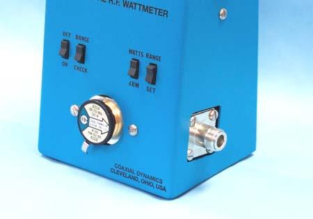
7 General Description The Model is designed to measure power in 50-Ohm transmission systems. It is for use with CW, AM, FM and TV modulation envelops, but is not for use with pulsed or digitally modulated transmitters. The insertion VSWR is less than 1.05:1 for frequencies up to 2300 MHz. The Model includes an internal line section with quick-match connectors and a large LCD display to display power. The full-scale power range currently active may be checked by pressing down the Range Check switch. The Wattmeter is normally supplied with type N female connectors. To avoid measurement errors caused by the use of between series adaptors we recommend the use of proper Quick-Match connectors. To make RF power measurements, the plug-in elements are inserted in the line section. Each element is designed and optimized for a particular power and frequency range. A latch is provided on the face of the line section to ensure that the element is properly seated. The contacts on the plug-in elements make connection with the DC pick-up only when the element is in either the forward or reflected direction. To properly indicate power on the LCD display, the range on the Model must be set to the range of the element in the line section. To set the range on the Model 81030, press and hold the range check switch and push down on the range set switch to lower the full scale range and lift up to increase the full-scale power range. The operation of this Wattmeter is based on the traveling wave concept of RF transmission. As RF is applied to a transmission line, there is a forward wave traveling from the transmitter to the load and a reflected wave traveling from the load toward the transmitter. The closer the load is matched to the transmission line, the smaller the reflected wave will be. To determine RF power dissipated in the load, it necessary to determine the power of the forward wave and the RF power of the reflected wave. The difference between the two is the power absorbed by the load. The interference between the forward and reflected waves produces a standing wave in the system. In the standing wave concept, VSWR is a widely used tool. There is a simple relationship between forward power, reflected power and VSWR. 5
8 Let Wf represent forward power Wr represent reflected power Then For example: 1% reflected power is about 1.2:1 VSWR and 10% is about 2.0:1 VSWR. It can be seen that VSWR is an index of the magnitude of the mis-match between the source and the load. The quantities of Wf and Wr are also an indication of the mis-match and are read directly on the Model Directional Wattmeter. When the Wattmeter is inserted in a transmission line the RF power flows through a precision section of 50-Ohm airline. The element installed in the line section socket is coupled capacitively and inductively to the main line. Voltages proportional to the RF voltage and current in the mail line are induced into the element circuitry. The coupling is adjusted such that the induced voltages add in the forward direction and cancel in the reflected direction when looking into a perfect 50 Ohm match. These voltages are rectified and the resulting DC voltage is applied to the circuitry for the LCD display, which is calibrated to represent the RF power in the main line. 6
9 Installation Check all components of the Wattmeter for damage. The battery charger is packed in the box with the Wattmeter. Report any damage promptly to your dealer or to the factory. Prior to use, make sure to charge the batteries for 8 hours to insure they have a full charge. The batteries used in the Model are high capacity AA NiCad. If they ever need to be replaced they must replaced with the same type. DO NOT USE ALKALINE TYPE BATTERIES Take reasonable precautions when handling the Wattmeter unit and plug-in elements. Make sure the thumbscrews that secure the spare elements are firmly tightened. Dropping and rough handling may change the calibration of the elements. Connections are made with any suitable coaxial cable directly to the quickmatch RF connectors mounted on the internal line section. Connect one side of the Wattmeter to the source and the other to the load. The Model Wattmeter is bi-directional, meaning the source and load can be connected to either side, since the direction of the element determines whether forward or reflected power is measured. Use only 50-Ohm cables to connect to the Wattmeter. Impedance mismatches will cause errors in readings. The Model is powered by 4 high capacity NiCad batteries. Make sure batteries are charged prior to use with the supplied charger. Do not use any chargers other than the one supplied with the Wattmeter. Safety First High Voltage Warning When operating this equipment with powers in excess of 200 Watts, the potential on the center conductor of the line section will be 100 Volts or higher. Do not contact the center conductor. If cleaning becomes necessary, turn off the RF power. 7

10 Figure 1 Wattmeter Dimensions Operation To make measurements with the Model 81030, it is necessary to first select an element with the proper frequency and power range, set the full-scale range of the Wattmeter by using the switches on the front. Press and hold the Range Check switch and use the Range Set switch to either raise or lower the range of the Wattmeter to match the element and connect the unit to the RF transmission line. Turn the arrow on the element toward the load and measure the forward power, turn the arrow toward the source and measure the reflected power. Subtract the reflected power from the forward power to get the power dissipated in the load. The Model will also display power in dbm by pressing the Watts/dBm switch. 8
11 The zero adjust is an internal electronic zero. There might be some slight deviation from zero with out any power applied, this is normal and will not affect the accuracy of RF power measurements. Use a plug-in element, which is designed for the frequency of the source, and select an element that is high enough power rating to properly indicate power in the RF line. If the power is not known, start with an element that will adequately cover the maximum power of the source to prevent damage to the Wattmeter. Use a more sensitive element if the indication is too low for accurate power determination. To determine load power, turn the arrow on the element so it points toward the load. Read the forward power in Watts on the LCD display. Rotate the element so the arrow points toward the source. Read the power in Watts on the display. Subtract the power reflected from the power in the forward direction. This is the power dissipated in the load or antenna. The Wattmeter is not designed to provide direct readings of VSWR. VSWR can be determined by either using the equations on page 3, or by using the chart on page 8. For power higher than represented on the chart, multiply both axes by 10 or 100. For lower powers, both axes may be divided by 10 or 100. When the reflected power is very low with respect to the forward power, it may be desirable to make reflected power measurements with more accuracy than is possible with the element used for forward power. Caution must be taken to prevent excessive power being applied to the low power element. When making measurements with the more sensitive element, be sure that the arrow points toward the source to prevent damage to the element. When using two elements to measure low reflected power, use a pair of elements with no more than 25 to one ratio between the high power element and the low power element. Each element is designed and optimized to operate over a specific frequency range. Operation outside of this range is not recommended. The frequency response of the element will drop off above and below the design range. 9
12 VSWR Nomogra Forward Power - Watts For higher power values multiply both scales by the same decim Reflected Power - Watts 10
13 Maintenance Maintenance of the Model is normally limited to cleaning. The amount of cleaning may be reduced by keeping an element or a dust plug in the socket and keeping the connectors either connected or covered. All connections must be kept clean to assure low resistance contacts. To clean the element socket, use a commercial contact cleaner or a cotton swab dipped in isopropyl alcohol. Pay particular attention to the bottom rim of the element body and the seat of the socket in the line section. When cleaning the socket in the line section, be careful not to disturb the finger of the DC contact. If necessary, the finger may be adjusted manually. The button must be positioned out far enough to make good contact with the element contact bar, but not far enough to restrict entry of the element. Safety First When using solvents, be sure to use in a well-ventilated area and avoid inhalation of any fumes. Most solvents are flammable, keep away from sparks of flames. Troubleshooting Trouble Possible Cause Remedy No Display Low Battery Charge Charge Batteries Display Reads Arrow on element turned in Correct arrow 000 wrong direction direction No pick up from DC Contact finger Adjust finger Intermittent Faulty Load Repair Load Readings Faulty Transmission Repair Line Line High Reflected Faulty Load Repair Load Power Poor Connectors Check All Connections Faulty Transmission Line Repair or Replace Line 11
14 88000 Series RF Quick Match Connectors N Female N Male BNC Female BNC Male UHF Female UHF Male LC Female LC Male C Female C Male /8 EIA Swivel Flange TNC Female TNC Male HN Female HN Male SMA Female SMA Male Others available. Specifications are subject to change without notice. 12
15

16 Contact Our World-Wide Network of Distributors or Coaxial Dynamics for Information on All Our Products Loads RF Meters Filters Couplers Termination Wattmeters Directional Power Detectors Digital Wattmeters Peak/Average Wattmeters
Instruction Manual. Model USB Wattmeter
 Instruction Manual Model 81041 USB Wattmeter TABLE OF CONTENTS Specifications and Leading Particulars. 2 General Description 1. Purpose and Application 3 2. Description. 3 3. Theory of Operation... 4
88950-A Series A Series INSTRUCTION MANUAL
 88950-A Series 98950-A Series INSTRUCTION MANUAL Specifications And Leading Particulars The 88950 and 98950 series Wattmeter is designed to work with any Coaxial Dynamics line section and the appropriate
Thruline RF Directional Wattmeters
 Portable Wattmeters BIRD S Famous ANALOG METER MODEL 43 Portable Wattmeter Power Range 100 mw - 10 kw using Bird Plug-in Elements.* Insertion VSWR with N Connectors 1.05 max. to 1000 MHz Finish Light Gray
Laboratory Grade Instruments Series & 4021 Power Meter SERIES Power Sensor
 Laboratory Grade Instruments 4020 Series & 4021 Power Meter Semiconductor 4020 SERIES Power Sensor 4021 4022 4024 4025 Power Input 300 mw to 1 kw 300 mw to 1 kw 3 W to 10 kw 3 W to 10 kw (1.2 kw max.)
AA-35 ZOOM. RigExpert. User s manual. Antenna and cable analyzer
 AA-35 ZOOM Antenna and cable analyzer RigExpert User s manual . Table of contents Introduction Operating the AA-35 ZOOM First time use Main menu Multifunctional keys Connecting to your antenna SWR chart
COM-POWER OPERATION MANUAL ACS W
 COM-POWER OPERATION MANUAL For the ACS-250-100W 150 khz to 250 MHz 100W Power Amplifier Page 1 of 15 MANUAL_ACS-250-100W Rev. M02.15 Table of Contents Important Safety Precautions.....3 Introduction..5
RigExpert AA-170 Antenna Analyzer (0.1 to 170 MHz) User s manual
 User s manual") RigExpert AA-170 Antenna Analyzer (0.1 to 170 MHz) User s manual Table of contents 1. Description... 3 2. Specifications... 4 3. Precautions... 5 4. Operation... 6 4.1. Preparation for use... 6 4.2. Turning
RigExpert AA-170 Antenna Analyzer (0.1 to 170 MHz) User s manual Table of contents 1. Description... 3 2. Specifications... 4 3. Precautions... 5 4. Operation... 6 4.1. Preparation for use... 6 4.2. Turning
310 DIVERSITY CAMERA-MOUNT UHF WIRELESS MICROPHONE SYSTEM
 310 DIVERSITY CAMERA-MOUNT UHF WIRELESS MICROPHONE SYSTEM 310UDR - 35BT - 35HT - 35XT INSTRUCTION MANUAL Thank you for purchasing the Azden 310 Diversity Wireless Microphone system. The components included
Technician Licensing Class. Lesson 4. presented by the Arlington Radio Public Service Club Arlington County, Virginia
 Technician Licensing Class Lesson 4 presented by the Arlington Radio Public Service Club Arlington County, Virginia 1 Quiz Sub elements T6 & T7 2 Good Engineering Practice Sub element T8 3 A Basic Station
MFJ ENTERPRISES 300 INDUSTRIAL PARK STARKVILLE, MS USA
 MFJ-819 MOBILE SWR/WATTMETER INSTRUCTION MANUAL PLEASE READ THIS MANUAL BEFORE OPERATING THIS EQUIPEMENT! MFJ ENTERPRISES 300 INDUSTRIAL PARK STARKVILLE, MS 39759 USA www.mfjenterprises.com 662-323-5869
330 DUAL-CHANNEL CAMERA-MOUNT UHF WIRELESS MICROPHONE SYSTEM
 330 DUAL-CHANNEL CAMERA-MOUNT UHF WIRELESS MICROPHONE SYSTEM 330UPR - 35BT - 35HT - 35XT INSTRUCTION MANUAL Thank you for purchasing the Azden 330 Dual-Channel Wireless Microphone system. The components
MFJ-249B HF/VHF SWR ANALYZER
 TABLE OF CONTENTS MFJ-249B... 2 Introduction... 2 Powering The MFJ-249B... 3 Battery Installation... 3 Alkaline Batteries... 3 NiCd Batteries... 4 Power Saving Mode... 4 Operation Of The MFJ-249B...5 SWR
MFJ-834 RF Ammeter. Introduction. Uses
 MFJ-834 RF Ammeter Introduction Congratulations on purchasing the MFJ-834 RF Ammeter. The MFJ-834 is designed for measuring in-line RF feedline current on 1.8-30 MHz while having low interaction on the
Dear Valued Customer,
 Dear Valued Customer, Thank you for choosing Listen! All of us at Listen are dedicated to provide you with the highest quality products available. We take great pride in their outstanding performance because
CALIBRATED IMPULSE GENERATOR MODEL CIG khz 1 GHz
 INSTRUCTION MANUAL CALIBRATED IMPULSE GENERATOR MODEL CIG-25 10 khz 1 GHz INSTRUCTION MANUAL THIS INSTRUCTION MANUAL AND ITS ASSOCIATED INFORMATION IS PROPRIETARY. UNAUTHORIZED REPRODUCTION IS FORBIDDEN.
Mirage B-320-G FEATURES
 Mirage B-320-G The Mirage B-320-G is a VHF power amplifier designed for 2 meters covering 144-148 MHz. The Hi and Lo input selector switch makes this amp useable for both handheld and mobile transceivers.
INSTRUCTION MANUAL LCS TX
 INSTRUCTION MANUAL LCS TX 4 Channel Transmitter LCS1 Single Channel Transmitter Cardio Theater Inc Service 1-800-776-6695 Sales 1-800-CARDIO-1 1 Introduction CONGRATULATIONS on your choice of this product
DEPARTMENT OF THE ARMY TECHNICAL MANUAL OPERATOR, ORGANIZATIONAL, FIELD AND DEPOT MAINTENANCE MANUAL
 TM -6625-446-5 DEPARTMENT OF THE ARMY TECHNICAL MANUAL OPERATOR, ORGANIZATIONAL, FIELD AND DEPOT MAINTENANCE MANUAL WATTMETER AN/URM-20 This copy is a reprint which includes current pages from Changes,
MFJ-969 Versa Tuner II Instruction Manual
 MFJ-969 Versa Tuner II Instruction Manual General Information The MFJ-969 is a 300 watt RF output power antenna tuner that will match any transmitter or transceiver to virtually any antenna. Peak or average
WARNING! IMPORTANT NOTICE
 WARNING! IMPORTANT NOTICE FCC type acceptance requirments prohibit sales of amplifiers operating below 144 MHz with internal RF sensing circuits that place the amplifier in a transmit mode. Because of
LC31L-BAT Link Coupler
 Instruction Manual For the LC31L-BAT Link Coupler 09 March 2018 2012-2018 by Ralph Hartwell Spectrotek Services All rights reserved 2 RADIO FREQUENCY WARNING NOTICE If the LC31L-BAT is installed incorrectly
DM-46 Instruction Manual
 Auto Meter Products Inc. Test Equipment DM-46 Instruction Manual Automotive Multimeter and Inductive Amp Probe The DM-46 is the auto industry s answer to pocket portability in a 20 2650-1552-00 3/8/11
Advanced Test Equipment Rentals ATEC (2832)
") Established 1981 Advanced Test Equipment Rentals www.atecorp.com 800-404-ATEC (2832) A.H. Systems Model Active Monopole Antennas Active Monopole Antenna Series Operation Manual 1 TABLE OF CONTENTS INTRODUCTION
Established 1981 Advanced Test Equipment Rentals www.atecorp.com 800-404-ATEC (2832) A.H. Systems Model Active Monopole Antennas Active Monopole Antenna Series Operation Manual 1 TABLE OF CONTENTS INTRODUCTION
WE-525T Antenna Analyzer Manual and Specification
 WE-525T Antenna Analyzer Manual and Specification 1.0 Description This product is designed to speed and ease the testing and tuning of antenna systems. Graphical displays of SWR, Return loss, Distance
2006 MFJ ENTERPRISES, INC.
 Model MFJ-842 INSTRUCTION MANUAL CAUTION: Read All Instructions Before Operating Equipment MFJ ENTERPRISES, INC. 300 Industrial Park Road Starkville, MS 39759 USA Tel: 662-323-5869 Fax: 662-323-6551 VERSION
32 CHANNEL SELECTABLE CH MHZ DOWN VOLUME
 KARAOKE Professional UHF Wireless Microphone System VM-92U Operating Instructions UHF Frequency 64 Selectable Better Music Builder UHF MIC WIRELESS SYSTEM VM-92U 32 CHANNEL SELECTABLE 248 13.10 CH MHZ
Professional UHF Rechargeable Wireless Microphone System POWER ON/OFF BATTERY CHARGE. Green Light (Full) Better Music Builder DOWN VOLUME
 Better Music Builder DOWN VOLUME") Green Light (Full) KARAOKE Professional UHF Rechargeable Wireless Microphone System VM-93C Operating Instructions UHF Frequency 64 Selectable POWER ON/OFF CHARGE Better Music Builder VM-93C CHARGER UHF
Green Light (Full) KARAOKE Professional UHF Rechargeable Wireless Microphone System VM-93C Operating Instructions UHF Frequency 64 Selectable POWER ON/OFF CHARGE Better Music Builder VM-93C CHARGER UHF
On-Line Cardio Theater Wireless Digital Transmitter Installation and Instruction Manual
 On-Line Cardio Theater Wireless Digital Transmitter Installation and Instruction Manual Full installation instructions accompany your Cardio Theater equipment order. This On-Line version of our Installation/Instruction
Safety Warnings Features Specifications Instrument Layout Operation Preparation AC Current Measurement How to Use Peak Hold Function How to Use The
 Safety Warnings Features Specifications Instrument Layout Operation Preparation AC Current Measurement How to Use Peak Hold Function How to Use The Frequency Selector Switch How to Use Data Hold Function
MIRAGE BD-38-G DUAL BAND POWER AMPLIFIER
 MIRAGE BD-38-G DUAL BAND POWER AMPLIFIER MIRAGE BD-38-G Dual Band Amplifier INTRODUCTION: The Mirage BD-38-G is a 80/60 watt dual band power amplifier for use with today's dual band handie talkies operating
Return Loss Bridge Basics
 1.0 Introduction Return loss bridges have many useful applications for the two-way radio technician These bridges are particularly helpful when used with the tracking generator feature of many service
Safety Warnings Features Specifications Instrument Layout Operation Preparation AC Current Measurement How to Use Peak Hold Function How to Use The
 Safety Warnings Features Specifications Instrument Layout Operation Preparation AC Current Measurement How to Use Peak Hold Function How to Use The Frequency Selector Switch How to Use Data Hold Function
Radio Control Installation and Operating Instructions System 4
 Radio Control Installation and Operating Instructions System 4 P.O. Box 403, One Cedar Parkway, Jackson, WI 53037 Phone: 800-628-1909 Fax: 262-677-2058 Revision: April 19, 2012 Contents Introduction 3
1997 MFJ ENTERPRISES, INC.
 INSTRUCTION MANUAL CAUTION: Read All Instructions Before Operating Equipment MFJ ENTERPRISES, INC. 300 Industrial Park Road Starkville, MS 39759 USA Tel: 601-323-5869 Fax: 601-323-6551 VERSION 6C COPYRIGHT
Users Manual. 200W HF/50MHz Band Auto Antenna Tuner. Model HC-200AT
 Users Manual 200W HF/50MHz Band Auto Antenna Tuner Model HC-200AT Caution 1. Never remove or open the tuner cover while transmitting. When there is RF in the circuits of the tuner, there will be high voltage
Transmission lines. Characteristics Applications Connectors
 Transmission lines Characteristics Applications Connectors Transmission Lines Connect They allow us to conduct RF Signals between our station components, they connect: Transceivers Antennas Tuners Amplifiers
INSTRUCTION SHEET WIDEBAND POWER SENSOR MODEL Copyright 2008 by Bird Electronic Corporation Instruction Book P/N Rev.
 INSTRUCTION SHEET WIDEBAND POWER SENSOR MODEL 5012 Copyright 2008 by Bird Electronic Corporation Instruction Book P/N 920-5012 Rev. C Description The Bird 5012 Wideband Power Sensor (WPS) is a Thruline
MFJ-219/219N 440 MHz UHF SWR Analyzer TABLE OF CONTENTS
 MFJ-219/219N 440 MHz UHF SWR Analyzer TABLE OF CONTENTS Introduction...2 Powering The MFJ-219/219N...3 Battery Installation...3 Operation Of The MFJ-219/219N...4 SWR and the MFJ-219/219N...4 Measuring
Introduction. Understanding Power Ratings. Peak Reading SWR/Wattmeter
 Introduction The MFJ-962D is a "T" network roller inductor tuner with built-in antenna switching, RF power and SWR metering and a 1:1 balun. The largest amplifiers that can safely be used include the Heathkit
GFL-1000 User Manual Ground Fault Locator
 GFL-Series User Manual V1.1 GFL-1000 User Manual Ground Fault Locator Contents Contents... 1 1 Declaration of Conformity... 3 2 Introduction... 3 3 Equipment Information... 3 3.1 Safety Precautions...
MFJ-836H SWR/Wattmeter and RF Ammeter
 Introduction MFJ8H SWR/Wattmeter and RF Ammeter The MFJ8H is an allinone true peak reading SWR/Wattmeter with a built in RF Ammeter designed to operate on.80 MHz. The SWR/Wattmeter uses our TrueActive
free solo HT UHF wireless system user manual
 free solo HT UHF wireless system user manual Musikhaus Thomann e.k. Treppendorf 30 96138 Burgebrach Germany Telephone: +49 (0) 9546 9223-0 E-mail: info@thomann.de Internet: www.thomann.de 22.01.2013 Table
MFJ-949E. tuner antenowy skrzynka antenowa. Instrukcja obsługi. importer:
 Instrukcja obsługi MFJ-949E tuner antenowy skrzynka antenowa importer: PRO-FIT Centrum Radiokomunikacji InRadio ul. Puszkina 80 92-516 Łódź tel: 42 649 28 28 e-mail: biuro@inradio.pl www.inradio.pl MFJ-949E
Additional JFW Brochures
 Additional JFW Brochures Test Systems Brochure Contains information on JFW's standard and custom RF test boxes, including: Matrix Switches Handover Test Systems Programmable Attenuator Assemblies Transceiver
MODEL FS-4 INSTRUCTION MANUAL R.L. DRAKE COMPANY, MIAMISBURG, OHIO, U.S.A.
 MODEL FS-4 F R E Q U E N C Y S Y N T H E S I Z E R INSTRUCTION MANUAL R.L. DRAKE COMPANY, MIAMISBURG, OHIO, U.S.A. LIMITED WARRANTY R. L. DRAKE COMPANY warrants to the original purchaser that this product
WARNING: DO NOT PROCEED WITHOUT READING THIS PAGE.
 WARNING: DO NOT PROCEED WITHOUT READING THIS PAGE. The B-1030-G produces at least 300 watts of VHF R.F. power and is not to be taken lightly. Severe R.W. burns can be sustained at this power level! Power
MFJ-835 RF Ammeter. Introduction. Uses
 MFJ-835 RF Ammeter Introduction Congratulations on purchasing the MFJ-835 Balanced Line RF Ammeter. The MFJ-835 is designed for measuring balanced RF feedline current on 1.8-30 MHz while having low interaction
Vectronics VC-300D DIGITAL BARGRAPH ANTENNA TUNER
 Vectronics VC-300D DIGITAL BARGRAPH ANTENNA TUNER FEATURES The Vectronics VC-300D Antenna Tuner optimizes the performance of your antenna and transmitter, receiver, or transceiver by providing adjustable
CBA 400M MHZ to 400 MHZ
 1 CBA 400M-100 1 MHZ to 400 MHZ 100 watt amplifier user Manual 601-298A CBA 400M-100 1 MHZ to 400 MHZ 100 watt amplifier USER Manual CBA 400M-100 User Manual contents 1 Safety information 5 2 Introduction
WARNING: DO NOT PROCEED WITHOUT READING THIS PAGE.
 WARNING: DO NOT PROCEED WITHOUT READING THIS PAGE. The B-2530-G produces at least 300 watts of VHF R.F. power and is not to be taken lightly. Severe R.W. burns can be sustained at this power level! Power
DM-46 Instruction Manual
 Test Equipment Auto Meter Products Inc. 413 West Elm Street Sycamore, IL 60178 Service (815) 899-0801 Toll Free (866) 883-TEST (8378) www.autometer.com/test DM-46 Instruction Manual Automotive Multimeter
VM-52U G2 UHF. Professional UHF Wireless Microphone System. Operating Instructions
 Unlike any others... that s cost & value for you Professional UHF Wireless Microphone System VM-52U G2 Operating Instructions UHF Frequency Selectable OFF OFF UHF WIRELESS SYSTEM VM-52U G2 UHF WIRELESS
High-Power Directional Couplers with Excellent Performance That You Can Build
 High-Power Directional Couplers with Excellent Performance That You Can Build Paul Wade W1GHZ 2010 w1ghz@arrl.net A directional coupler is used to sample the RF energy travelling in a transmission line
free solo PT UHF wireless system user manual
 free solo PT UHF wireless system user manual Musikhaus Thomann e.k. Treppendorf 30 96138 Burgebrach Germany Telephone: +49 (0) 9546 9223-0 E-mail: info@thomann.de Internet: www.thomann.de 22.01.2013 Table
ALWAYS ATTACH THE SAFETY ROPE TO A STABLE SUPPORT BEFORE ATTEMPTING TO ATTACH THE UNIVERSAL MOUNT TO A WINDOW FRAME OR RAIL.
 MFJ-1623 Introduction The MFJ-1623 was designed to provide portable or permanent HF communications on 30 through 10 meters and VHF on 6 meters. The universal mount design allows the user to install the
Technician Licensing Class. Antennas
 Technician Licensing Class Antennas Antennas A simple dipole mounted so the conductor is parallel to the Earth's surface is a horizontally polarized antenna. T9A3 Polarization is referenced to the Earth
PLEASE READ THIS MANUAL BEFORE ATTEMPTING TO OPERATE EQUIPMENT!!
 PLEASE READ THIS MANUAL BEFORE ATTEMPTING TO OPERATE EQUIPMENT!! UNPACKING INSTRUCTIONS 1. Carefully lift the amplifier by the bottom cabinet edge out of the shipping carton. Place the amplifier on a firm,
FCC STATEMENT This device complies with part 74, Subpart H of the FCC rules. Operation is subject to the following two conditions: (1)This device may
This device may") FCC STATEMENT This device complies with part 74, Subpart H of the FCC rules. Operation is subject to the following two conditions: (1)This device may not cause harmful interference and (2) This device
FCC STATEMENT This device complies with part 74, Subpart H of the FCC rules. Operation is subject to the following two conditions: (1)This device may not cause harmful interference and (2) This device
Introduction. Controls and Locations
 Introduction Congratulations on purchasing the MFJ-854 RF-Current Meter. The MFJ-854 is designed for measuring current distribution on antenna elements and radials, and for checking common-mode current
User's Manual F10G-5S-LCD 1 / 20 BOOST CELL PHONE SIGNAL BOOSTERS MADE BY HUAPTEC
 User's Manual F10G-5S-LCD 1 / 20 BOOST CELL PHONE SIGNAL BOOSTERS MADE BY HUAPTEC Table of contents WHAT IS INCLUDED... 3 1 HOW IT WORKS... 3 2 TOOL REQUIRED... 3 3 HOW TO INSTALL YOUR NEW CELLULAR BOOSTER...
VECTRONICS HFT-1500 Digital Bargraph Antenna Tuner
 Table of Contents FEATURES... 1 SPECIFICATIONS... 1 FRONT PANEL INDICATORS AND CONTROLS... 1 CONTROLS... 1 REAR PANEL CONNECTORS... 1 OTHER... 2 CONTOLS / CONNECTORS... 2 FRONT PANEL FUNCTIONS... 2 REAR
UAT-600 Series. amprobe.com
 UAT-600 Series Underground Utilities Locator Accurately and safely pinpoint underground utilities before you dig Accidentally hitting a utility line during a project can lead to costly repairs and create
ALM473 DUAL MONO \ STEREO AUDIO LEVEL MASTER OPERATION MANUAL IB
 ALM473 DUAL MONO \ STEREO AUDIO LEVEL MASTER OPERATION MANUAL IB6408-01 TABLE OF CONTENTS GENERAL DESCRIPTION 2 INSTALLATION 2,3,4 CONNECTION AND SETUP 4,5,6,7 FUNCTIONAL DESCRIPTION 8,9 MAINTENANCE 9
3100LA Broadband Power Amplifier
 3100LA Broadband Power Amplifier HIGH RF VOLTAGES MAY BE PRESENT AT THE OUTPUT OF THIS UNIT. All operating personnel should use extreme caution in handling these voltages and be thoroughly familiar with
Installation & Operation Manual SAGA1-K Series Industrial Radio Remote Control
 Installation & Operation Manual SAGA1-K Series Industrial Radio Remote Control Gain Electronic Co. Ltd. Table Of Contents Safety Considerations ------------------------------------------------------------2
Opus 21 s80 Integrated Amplifier Owner's Manual
 Opus 21 s80 Integrated Amplifier Owner's Manual r e s o l u t i o n From all of us at Resolution Audio, thank you for choosing the Opus 21 s80 amplifier. We went to great lengths to design and produce
PAMS. User s Manual. Portable Attenuation Measurement System. The solution for making easy shielding effectiveness measurements.
 PAMS Portable Attenuation Measurement System User s Manual The solution for making easy shielding effectiveness measurements. 310-010042-001 TABLE OF CONTENTS Warranty Statement 1 Chapter 1 General Information
433 & 443 Series INTELLIGENT RELAY SP3T & SP4T IN-LINE Multithrow Switches
 433 & 443 Series INTELLIGENT RELAY SP3T & SP4T IN-LINE Multithrow Switches Available with two types of internal drive electronics (Binary Decoding or MOSFET Pulse Latching), these SP3T and SP4T IN-LINE
INDEX PREFACE... 1 CAUTIONS... 2 OPERATION ON SITE(9) STANDARD INSTRUMENT... 3 OPTIONAL ACCESSORIES... 4 OPERATION OF TRANSMITTER(3)...
 STANDARD INSTRUMENT... 3 OPTIONAL ACCESSORIES... 4 OPERATION OF TRANSMITTER(3)...") INDEX PREFACE... 1 CAUTIONS... 2 STANDARD INSTRUMENT... 3 OPTIONAL ACCESSORIES... 4 OPERATION OF TRANSMITTER(1)... 5 (Transmitter Unit.) OPERATION OF TRANSMITTER(2)... 6 (Operation Panel, LCD Display of
INDEX PREFACE... 1 CAUTIONS... 2 STANDARD INSTRUMENT... 3 OPTIONAL ACCESSORIES... 4 OPERATION OF TRANSMITTER(1)... 5 (Transmitter Unit.) OPERATION OF TRANSMITTER(2)... 6 (Operation Panel, LCD Display of
free solo HT UHF wireless system user manual
 free solo HT UHF wireless system user manual Musikhaus Thomann Thomann GmbH Hans-Thomann-Straße 1 96138 Burgebrach Germany Telephone: +49 (0) 9546 9223-0 E-mail: info@thomann.de Internet: www.thomann.de
free solo HT 1.8 GHz UHF wireless system user manual
 free solo HT 1.8 GHz UHF wireless system user manual Musikhaus Thomann Thomann GmbH Hans-Thomann-Straße 1 96138 Burgebrach Deutschland Telephone: +49 (0) 9546 9223-0 E-mail: info@thomann.de Internet: www.thomann.de
The Maintenance Shift
 The Broadcasters Desktop Resource www.thebdr.net edited by Barry Mishkind the Eclectic Engineer The Maintenance Shift VSWR Calibration Techniques By Stephen Rutherford [September 2014] Among the important
The Principle V(SWR) The Result. Mirror, Mirror, Darkly, Darkly
 The Result. Mirror, Mirror, Darkly, Darkly") The Principle V(SWR) The Result Mirror, Mirror, Darkly, Darkly 1 Question time!! What do you think VSWR (SWR) mean to you? What does one mean by a transmission line? Coaxial line Waveguide Water pipe Tunnel
The Principle V(SWR) The Result Mirror, Mirror, Darkly, Darkly 1 Question time!! What do you think VSWR (SWR) mean to you? What does one mean by a transmission line? Coaxial line Waveguide Water pipe Tunnel
PA FAN PLATE ASSEMBLY 188D6127G1 SYMBOL PART NO. DESCRIPTION. 4 SBS /10 Spring nut. 5 19A702339P510 Screw, thread forming, flat head.
 MAINTENANCE MANUAL 851-870 MHz, 110 WATT POWER AMPLIFIER 19D902797G5 TABLE OF CONTENTS Page DESCRIPTION.............................................. Front Page SPECIFICATIONS.................................................
Model 310H Fast 800V Pulse Generator
 KEY FEATURES Temperature Stability +/-5ppm 100 V to 800 V into 50 Ω
Broadband Power Amplifier
 601L Broadband Power Amplifier HIGH RF VOLTAGES MAY BE PRESENT AT THE OUTPUT OF THIS UNIT. All operating personnel should use extreme caution in handling these voltages and be thoroughly familiar with
Transmission Line Signal Sampling By Don Steinbach, AE6PM
 Transmission Line Signal Sampling By Don Steinbach, AE6PM When I was finalizing the mechanical layout of my remotely-operated 3-position coaxial antenna switch (Fig. 1), I wanted to include a way to bring
Attenuators 39. Attenuators. Accuracy. Applications. Key specifications SWR
 Attenuators Attenuators 39 Applications Agilent fixed and step attenuators 1 find use in a wide variety of applications for signal conditioning and level control. Reducing signal levels Matching impedances
411LA Broadband Power Amplifier
 411LA Broadband Power Amplifier HIGH RF VOLTAGES MAY BE PRESENT AT THE OUTPUT OF THIS UNIT. All operating personnel should use extreme caution in handling these voltages and be thoroughly familiar with
MIRAGE BD-35 DUAL BAND POWER AMPLIFIER
 MIRAGE BD-35 DUAL BAND POWER AMPLIFIER INTRODUCTION: The Mirage BD-35 is a 45/35 watt dual band power amplifier for use with today's dual band handie talkies operating in the 144/440MHz bands. We have
2100L Broadband Power Amplifier
 2100L Broadband Power Amplifier HIGH RF VOLTAGES MAY BE PRESENT AT THE OUTPUT OF THIS UNIT. All operating personnel should use extreme caution in handling these voltages and be thoroughly familiar with
OPERATING MANUAL CAVITY DUMPER / PULSE PICKER DRIVER MODEL NUMBER: 643ZZ.ZZZ-SYN-Y-X
 OPERATING MANUAL CAVITY DUMPER / PULSE PICKER DRIVER MODEL NUMBER: Where: X is the division factors for the pulse rate. Y is the multiplier of the reference input frequency 3ZZ.ZZZ is the output RF frequency
Model Model Digital Power Meter. Digital Power Sensor Digital Display & Analog RF Systems
 Model 5000 Digital Power Meter Model 5010 Digital Power Sensor Digital Display & Analog RF Systems The NEW Industry Standa The NEW Industry Standard Hand-Hel Hand-Held RF Power Meter RF Power Met Serial
Mirage B-310-G FEATURES
 Mirage B-310-G Mirage B-310-G Instruction Manual The Mirage B-310-G is a VHF power amplifier designed for the 144-148 MHz band. New features make it the most useful and versatile amplifier available for
The Amazing MFJ 269 Author Jack Tiley AD7FO
 The Amazing MFJ 269 Author Jack Tiley AD7FO ARRL Certified Emcomm and license class Instructor, Volunteer Examiner, EWA Technical Coordinator and President of the Inland Empire VHF Club What Can be Measured?
Installation & Service Manual
 869-894 MHz Installation & Service Manual Model SCA 9321-30C Single-Channel Cellular Amplifier 044-xxxxx Rev.A February 2003 2003 Powerwave Technologies Incorporated. All rights reserved. Powerwave Technologies,
Appendix A: BLC-10/20/25 DC Models Packing
 Appendix A: BLC-10/20/25 DC Models Packing List BLC-10/20/25/40/50 User Manual Appendix A: BLC-10/20/25 DC Models Packing List Description Belcom P/N Quantity BLC-10/20/25 BLC 10/20/25 1 Installation Kit,
Synthesized Transmitter
 SONY. 3-860-341-32(1) UHF Synthesized Transmitter Operating Instructions WRT-805A 1997 by Sony Corporation Precautions... Introduction... Features... Channels and Carrier Frequencies... Parts Identification...
SWR TRUE Antenna Analyzer
 SWR TRUE Antenna Analyzer Operators Manual Edition Notice! This publication applies to the following COMM-connect A/S products: SWR True, type 3013, SWR Analyzer Hardware release 2 Software release 3013
A 500 Broadband Power Amplifier
 A 500 Broadband Power Amplifier HIGH RF VOLTAGES MAY BE PRESENT AT THE OUTPUT OF THIS UNIT. All operating personnel should use extreme caution in handling these voltages and be thoroughly familiar with
Operating Instructions CAMILLE BAUER METRAWATT METRAOHM /9.97. Low impedance resistance meas. instrument
 Operating Instructions METRAOHM 413 Low impedance resistance meas. instrument GOSSEN METRAWATT CAMILLE BAUER 3-348-776-37 2/9.97 V 8 6 5 4 20 200 PE-TEST 7 1 20 200 + /- METRAOHM 413 3 2 10 9 1 Measurement
VECTRONICS. VC-300DLP Antenna Tuner
 VECTRONICS VC-300DLP Antenna Tuner FEATURES The Vectronics VC-300DLP Antenna Tuner optimizes the performance of your antenna and transmitter, receiver, or transceiver by providing adjustable impedance
free solo PT UHF wireless system user manual
 free solo PT UHF wireless system user manual Musikhaus Thomann Thomann GmbH Hans-Thomann-Straße 1 96138 Burgebrach Germany Telephone: +49 (0) 9546 9223-0 E-mail: info@thomann.de Internet: www.thomann.de
Specification for Radiated susceptibility Test
 1 of 11 General Information on Radiated susceptibility test Supported frequency Range : 20MHz to 6GHz Supported Field strength : 30V/m at 3 meter distance 100V/m at 1 meter distance 2 of 11 Signal generator
Atomscope PORTABLE VETERINARY X-RAY EQUIPMENT INSTRUCTION MANUAL. Version 1.0
 Atomscope PORTABLE VETERINARY X-RAY EQUIPMENT INSTRUCTION MANUAL Version 1.0 Thank you for purchasing our HFX90V portable veterinary x-ray unit. We are confident that you will be pleased with the radiographs
Model 4007DDS. 7 MHz Sweep Function Generator
 Model 4007DDS 7 MHz Sweep Function Generator 1 Model 4007DDS - Instruction Manual Limited Two-Year Warranty B&K Precision warrants to the original purchaser that its products and the component parts thereof,
TA-80. Digital Plug-on Transmitter
 Digital Plug-on Transmitter MIPRO Digital Plug-on Transmitter The ways how microphone output connects to sound system The microphone output connects to sound system with a microphone cable is the easiest
RU210. Dual Multi-UHF Wireless System. Item ref: UK, UK User Manual. Version 1.0
 RU210 Dual Multi-UHF Wireless System Item ref: 171.970UK, 171.971UK User Manual Version 1.0 Caution: Please read this manual carefully before operating Damage caused by misuse is not covered by the warranty
IEM-75 UHF wireless system. user manual
 IEM-75 UHF wireless system user manual Musikhaus Thomann Thomann GmbH Hans-Thomann-Straße 1 96138 Burgebrach Germany Telephone: +49 (0) 9546 9223-0 E-mail: info@thomann.de Internet: www.thomann.de 02.09.2015,
Many applications. Mismatched Load Characterization for High-Power RF Amplifiers PA CHARACTERIZATION. This article discusses the
 From April 2004 High Frequency Electronics Copyright 2004 Summit Technical Media, LLC Mismatched Load Characterization for High-Power RF Amplifiers By Richard W. Brounley, P.E. Brounley Engineering Many