Current Trends on Command, Control, Modeling and Simulation of the Induction Machines
|
|
|
- Jeffrey Stevenson
- 6 years ago
- Views:
Transcription
1 Current Trends on Command, Control, Modeling and Simulation of the Induction Machines MARCEL IONEL *, MIHAIL-FLORIN STAN **, ELENA-OTILIA VÎRJOGHE ** * Electronics, Telecommunications and Energy Engineering Department ** Automatics, Informatics and Electrical Engineering Department Valahia University Targoviste, Electrical Engineering Faculty Unirii Ave., Targoviste ROMANIA ionel.marcell@yahoo.com, flo.stan@gmail.com, otiliavirjoghe@yahoo.com, Abstract: - AC motor drives have produced and still produce a particularly high impact in many technical applications. Advantages of adjusting the frequency operation can not be fully exploited without adjustment command and control strategies through modeling of the corresponding components. Simulation of drive systems is complicated due to nonlinear high level they bring power electronics and also due to control, adjustment and protection in the transfer of power flux. Moreover, mathematical models of semiconductor and control functions not yet found in many programs and this requires the designer or specialist to introduce its version in the simulation program [1]. Currently known multi-level modeling, which is available to describe static converters and each model can introduce undesirable effects on the behavior of electric machine [2]. This paper presents the current trends of advanced control techniques and control of induction machines used for variable frequency drives, depending on the torque, speed and rotor position. It analyzes the possibilities of command and control without sensors and estimates are made of results obtained by modeling and simulation of the control and adjustable system. Also, present paper recommends how to run a simulated vector controlled induction electric machines. Key-Words: - Non-sensorial control, vector control, parameter estimation, modeling drive system, model of vector controlled electric drive system, block diagram, mathematical models, micro-models, macro-model. 1. Introduction As known from literature on systems theory adjustment for AC motors drives controlled by conventional vectors, control system requires rotor position transducers for the stator current vector orientation at a given angular displacement depending on the rotor flux. This should be done in correlation with construction and functional characteristics of AC motor. Where necessary the direct control of torque by the stator current command in amplitude, we want to hear instantaneous angular position of rotor flux with a well-defined system in terms of mathematics [3] and physics. 2. Drive systems using different types of transducers In general block diagram of Fig. 1 shows a synchronous motor drive system (you can also use an induction motor) ordered by speed control, including vector control field. On the kinematics axis of the system are involved two electromechanical transducers while speed transducer is used to implement closed loop speed control. Transducer position is used only to obtain the total torque and flux control. Position transducers that can be used, flux sensors / transducers with Hall Effect or optical systems coded transducers. All these transducers increase the cost, size and complexity of induction motors, and often-reduced and system reliability, seriously limiting the practical application. This limitation affects not only induction motors but even those that use non-standard motors, such as variable reluctance synchronous motors (motors which are now recommended as an alternative for induction motors). Although it may seem as a good solution in many applications (such as shareholders with average performance, but at reduced prices), the presence of transducer position affects the overall cost of operation. An application of this type can be made to order in the rolling mills stands, where even reach 9MW power electric machine, however, rate control do not require a very high precision. ISSN: Issue 2, Volume 5, February 2010


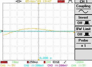
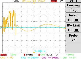
2 Fig. 2. Voltage forms at the terminals of an induction motor ordered with a variable frequency converter in the operating mode to 10 Hz. Fig. 1. Block diagram of a system drive synchronous motor vector control 3. Command and control of non-sensors schemes In general, an effective scheme of non-sensor control speed or an efficient scheme to estimate the position should be involved only standard sensors always included in drive systems. Typical electrical variables can be measured directly and those derived from measurable quantities include voltage, current, time of growth and decrease the switching current, inductance, total flux and response f.e.m. Figures 2, 3 and 4 are exemplified changes in the system voltage at the terminals of the machine operating at 10Hz (Fig.2 and Fig.3) and in the braking operating at 10 Hz (Fig.4). Figures 5, 6, 7, 8, 9 and 10 exemplifies the voltage variations at the terminals of the induction machine operating at 20Hz, 30Hz and 50 Hz (fig.5, 6 and 7) and in the braking operation at 20Hz, 30Hz and 50 Hz (Fig.8, 9 and 10). In fig. 9 is observed the transient regime in the passing of the asynchronous machine from operating regime thru the braking operating regime. Fig 3. Voltage drop on a semiconductor device of a variable frequency converter operating to 10 Hz. Fig 4. Voltage forms at the terminals of an induction motor ordered with a variable frequency converter in the braking operation to 10 Hz. ISSN: Issue 2, Volume 5, February 2010


3 Fig. 5. Voltage forms at the terminals of an induction motor ordered with a variable frequency converter in the operating mode to 20 Hz. Fig 8. Voltage forms at the terminals of an induction motor ordered with a variable frequency converter in the braking operation to 20 Hz. Fig. 6. Voltage forms at the terminals of an induction motor ordered with a variable frequency converter in the operating mode to 30 Hz. Fig 9. Voltage forms at the terminals of an induction motor ordered with a variable frequency converter in the braking operation to 30 Hz. Fig. 7. Voltage forms at the terminals of an induction motor ordered with a variable frequency converter in the operating mode to 50 Hz. Fig 10. Voltage forms at the terminals of an induction motor ordered with a variable frequency converter in the braking operation to 50 Hz. It requires that non-sensor scheme have easy and flexible implementation and can be applicable to most drive the same kind, without modifications in ISSN: Issue 2, Volume 5, February 2010
4 the structure of machines or additional installation systems. Accuracy must be less than 0.5 revolutions per minute for the detection of speed, while for field orientation control schemes usually requires a resolution of 8 bits (10 24 ') and 16 bits for servo control of motion. This type of control can be achieved with a frequency converter like Fig.11. Basic speed range of 1:100 to 1:150 should be provided for minimum stator frequency, 1 Hz level, low torque and reliable control for zero speed. Such performance is currently offered by existing schemes non-sensor (fig.11), while improving accuracy and effective active operation zero stator frequency are goals that are still growing. Modeling and simulation non-sensor estimate schemes of speed in low - medium performance drives rotor frequency estimation allows a calculation about the f.e.m., which is defined as a change in time of rotor flux. The f.e.m. answer is calculated from current and voltage signals. Rotor frequency estimator can be used in a drive system controlled by a low frequency filter. This filter is inserted to avoid stability problems, but, unfortunately, reduces the system dynamic performance. In high performance drives, field oriented control can be obtained by calculating the rotor flux. It can be expected, in turn, the current and terminal voltage. In a speed non-sensor scheme, signal speed can be obtained also through technical estimates. According to the model approach the stator voltage, stator flux is estimated by integrating the stator voltage, after withdrawal of fall of tension on the stator resistance: λ = v R i dt ( ) qds qds s qds (1) It is calculated rotor flux by highlighting the stator and rotor leakage reactance. With all that is good behavior on almost the entire range of speed, flux estimates obtained with the above expression is affected, especially at low frequencies: digital approximation errors, disturbances, measurement of voltage, current deviation, mistuning of parameters, etc. Another method for flux estimating is to use a separate flux estimate, derived from rotor current model: λ qdr = τ r L m i ( p+ jω ) qds 1 (2) τ r r Fig.11. Command and indirect control of induction machine with a PWM frequency converter by field orientation with position and speed transducer incorporated The two methods are used together to estimate the rotor speed. The calculation of errors in estimates of stator and rotor flux models, followed by minimizing the error rate evaluation may be forced to converge to its true value. The stator serves as a reference, while the rotor model has adjustable parameters that can be forced to produce the same vector as that of runner flow reference model. Thus, we perform an adaptive control system where the adjustment mechanism may be a simple PI controller or a more complicated algorithm based on Lyapunov criterion or even the logic of diffuse. But such sophisticated techniques can prevent errors introduced by these non-sensor schemes. The two models above are, in fact, two "surfaceflow" based on schemes which seek to identify flux and speed simultaneously. Variants of this scheme are practical multiple, since it is one of the most interesting research topics in recent years in the field. The rotor can be used to ISSN: Issue 2, Volume 5, February 2010
5 estimate the speed or, as proposed, for estimating torque. Later, the obtained torque can be used to determine speed estimates required by the rotor model; a non-linear nature observer complete the observers of sliding, non-linear observers of reduced order etc. Extended Kallman filters are able to provide additional techniques more acceptable performance as the mechanical speed reduces. Estimated speed can be obtained, also thru determinations of the effects of the magnetic machine. The slots of the rotor magnetic core produce harmonics (depending on speed) that can be found in the stator current waveform. Distortions are due to rotor slots or its eccentricity or imbalance caused by the driver, leaving the field or power asymmetries of the rotor. The determined characteristics provide a set of information allowing the derivation of rotor speed of the fundamental harmonic frequency of stator voltage. Speed detection algorithms are based on digital filtering and sampling, followed by spectral estimation to reduce the time of sampling as the accuracy required, followed by reporting the rotor speed. Higher rotor harmonics modulate stator flux drops with a frequency proportional to the rotor speed. The parameters read heads placed particular stator windings, higher harmonic signals can be separated by a fundamental f.e.m., because they distinguish the change in frequency, while the third order voltage components are deleted. The suppression of harmonic components - other than the fundamental harmonic - an adaptive filter bandwidth, the speed signal is obtained proportional to their frequencies. Accuracy of detected speed is bad because of the limited information on the winding rotor, which is leading to a moderate speed dynamic control but maintaining a considerable accuracy even at a high speed. Methods based on test signal injection on a machine phase are recommended for applications with low speeds. The signal contains information of rotor position and it may be directly or inversely proportional to the rotor position. Modulation techniques of machine parameters (phase, frequency or amplitude modulated position) are in this class and all are based on injecting a voltage-carrying high-frequency sinusoidal form. Each of the carrier signal parameters change with changing the instantaneous value of information obtained after applying a strategy for determining which allows deduction of the initial signal modulated signal. With all that is insensitive to interference by switching intervals, these methods are not recommended in schemes with a large number of electronic circuits and microprocessors in control circuits. This leads to limiting the flexibility of their control. All additional methods of reading the position, based on inductance variation in terms of the rotor position, involving a modified switching inverter. Current regulator may extend the period of transition through zero of phase current by decupling both switches on the same stage. During such an extended period zero crossing, the other two phase currents are controlled as a constant reference current. The induced voltage in no leading phase contains information about that phase inductance and can be used effectively to estimate rotor position. It is very important to mention among other techniques that the method based on measuring the current in the hysteresis controller is used to obtain information on the inductance that is contained in current relationship: - Method based on reconstruction of rotor position of stator currents and voltages; - Method based on indirect detection by measuring flow in the line of reactants. Techniques based on observation, on measurement of third order harmonic voltage phase, on the methods of control slipping induction machine are made with good accuracy, but involves a calculation difficult requiring faster microprocessors. It should be noted and that most non-sensor schemes currently adopted is based on simplistic considerations (such as saturation neglecting and neglecting the effects of time and temperature variation on inductance, the inductance unbalance perfect in connection with the rotor position and geometry of the tooth-shaped poles, stator and rotor). Finally, should be taken into consideration also the influence in the iron losses on algorithms instituting the position. 4. Methods and levels of modeling The multiple levels of modeling (which are available to describe static converters) will further detail some. The first method for the mathematical model is linked to the process of switching semiconductor inside the static converter, with the introduction of the control algorithm may be achieved practical. ISSN: Issue 2, Volume 5, February 2010
6 These types of models should be simulated depending on time with small steps to be able to see how the converter can generate wave forms of current and voltage at the terminals of electric machine regardless of its operational arrangements. It should also be considered as the input signal to the device training pulse u c command for changes to the switch. To this end, there are several models of semiconductor that can be developed, namely the idealized assumption of ideal semiconductor switch to a real representation of physical behavior, described by equations of the internal converter [4]. The second method introduces the mathematical model simplifications on static converter using a description of waveform output with analytical functions between discontinuities introduced by the converter and electrical machines. This technique allows the study of harmonic effects on transient and mechanical processes of the machine during operation. It required precise knowledge of component and operation of static power converters to be able to describe the functions of time out, taking into account the signal form detached u c. In the third method is compared with the simplest model of the converter power using a description with one variable gain K and a time constant T, which can also be variable. This last method does not introduce any harmonic, but show the entire command and control of mechanical and electrical drive system. The first two methods are known as micromodels of electric drive systems while the last method is called macro-model [5], [6], [7]. 5. Basic Electrical Diagrams Vector Control of an Induction Machine Induction machine is loaded with a working machine with a full load inertia J and the coefficient of friction f. Stator of electric machine is connected to a three phase VSI inverter associated with a three phase rectifier. In Fig.12 is presented the method that can run simulating a vector controlled induction electric machines. Electric drive system is powered by an electric network with a highly inductive and the current progress in the circuit of rectifier and inverter, we consider capacitive filter element. Compared to the above analysis is to determine the frequency converter circuit model intermediate DC voltage constant [8]. Fig. 12. Basic electrical diagram and block diagram for a drive of an induction machine ordered by a frequency converter Command and control circuits have been reduced from continuous time functions to complex linear functions. The controller torque (current) type is full - in proportion to the current prescribing limited to a loop with a positive reaction for flow control in electric machine. Current loops are carried out by using hysteresis controllers that can execute commands most current independent electric drive systems encountered in practice. This last feature may be different from other industrial applications such as a simple hysteresis controller leads to tensions within the switchable variable frequency inverter and applied in the winding machine. In most modern electric drive system control is implemented using digital microprocessors that can ISSN: Issue 2, Volume 5, February 2010
7 be simulated by the same wording as analog controllers, but with different equations and the selectors (switches sampling) and supports instead of Laplace functions comprehensive s [9]. In the proposed scheme, the regulator comes ω sref speed transmission, a convenience factor and voltage depends on the function V s Indus reducing field (field-weakening function) both constant torque and constant power schemes on. Speed regulator is equipped with a dynamic limiter is included to provide anti-windup for reference output torque, while the reference current is also limited as to correspond with the conversion of power. Park transformation is related to switching currents of phase currents using as input the torque (torque currents) and currents flow and also ω ref reference position. In all schemes, it is assumed that the machine parameters are constant and hence will not depend on temperature or level of saturation [10]. Current regulators use current reference and the processed actual values are taken as input two phase currents (current actual). The output of pulses is the trainer of command sequences (primer and extinction) of the semiconductor. In the charts below (Fig.13.) are represented variation of voltage and current variation from connecting to the network through a drive [11], [12]. switching power converters and suppose that perform the functions without any error. If the proposed VSI is controlled by DC, which means that we have the stator currents, equivalent to the reference currents give the control block diagram. To perform this task is of interest to remove the stator transient processes and to relate measurements to measurements of induction machine rotor and the mechanical transient processes taking into account the electromagnetic torque equations of the machine. Electric machine is described by the following equation [13]: where: ' dr ' r 'e dr 'e dr ' e ( ω ω ) λ ν = r i + p λ (1) 'e 'e 'e dr dr qr = e ν = 0, p λ = 0, λ 0 (2) and i e dr = 0, X e dr = L m i e ds (3) T em = K a Φ ( I f ) I a (4) dωrm J = Tem + Tmem T (5) damp dt (1),(2),(3) = rotor equations; (2) = torque equation; (3) = mechanical equation. r qr > 1) Ref A: 2 Volt 5 ms 2) Ref B: 2 Volt 5 ms Fig. 13. Waveforms of voltage and current time according to the output terminals of the frequency converter 6. Macro-Model Drives System for Electric Induction Machine To define a macro-model for driving a vector controlled induction machines, it is necessary to remove all sequences released in the process of In the proposed scheme, power regulators, voltage, speed and torque although different in role and structure were represented in the same way as the basic circuit model. The only difference is that electric machine model represented in Fig. 14, reflects primarily the simplifications presented over Fig 12. It is obvious that such a block diagram can be simulated by a control method such as dedicated software (MATLAB, MATRIX-X). However, it can be adapted to other control systems, allowing integration of equations (1), (2), (3),(4),(5) equivalent nonlinear differential algebraic functions and linear equations (in our case in the complex simplified). It emphasized that the mathematical functions of the control system are very close to the basic scheme and only the machine models and power converter electronics are changed into blocks of nonlinear equations including rotor torque expressions and of course, mechanical model played a set of differential equations linear or nonlinear. ISSN: Issue 2, Volume 5, February 2010
8 The induction machine is introduced in topology power converters using voltage-controlled sources and possibly a equivalent electrical circuit for the mechanical load. Thus, control functions are based on block diagram defined in the macro-model, which is complemented by control schemes related to the power converter and induction machine model. These features are not represented in micromodel scheme because they have developed special features included in the simulation. This approach requires a mixed representation of the power grid and is also on complicated control functions and is not a feature included in many programs. Fig. 14. Block diagram representation of the macromodel of vector controlled induction machines The nonlinear block can be modified and turned into a subsystem, with representation by block diagrams. This option is recommended to use control-oriented programs with libraries of predefined blocks [14]. 7. Micro-Model of Electric Systems Drive Machine Induction When it is necessary to simulate the complete control of the converter algorithms for power, the previous model is not suitable and should be extended. In this case, it be defined micro-model power converter topology and include the semiconductor switch. The low level of power converter model involving the replacement of each semiconductor with linear elements is shown below (Fig.15). Fig. 15. Simplified electric scheme for the micromodel of vector controlled induction machine ISSN: Issue 2, Volume 5, February 2010
 and to remove simulation processes extended, is necessary to initialize variables input power and rotor currents and capacitive voltages of the")
9 The electricity grid, all diodes are associated with groups of RC surge protection to remove numerical oscillations. Proposed power converter has two stages (phases) and to remove simulation processes extended, is necessary to initialize variables input power and rotor currents and capacitive voltages of the intermediate circuit [15]. Currents control algorithms defined in the current regulator can be achieved by analog or digital functions (in fact are made by two-phase currents as input and output signals and control the power semiconductor gate). The induction machine can develop and using internal tension control voltage sources as Fig.16. Fig.16. Order 132 KW Induction machine by controlling the voltage sources Fig.17. Current variation from 132 kw asynchronous machine by the power source control variable torque 8. Conclusions The article provides a uniform treatment of issues relating to implementation, analysis, simulation and control systems for electric drives of high power induction machines emphasizing the practical application in heavy industry particularly in metallurgy where prevailing adjustable drives of all types. Very rapid development of asynchronous motors with variable speed drives and electric power conversion systems has made the technical development in the field to achieve unprecedented. Nowadays, the share of asynchronous machines is becoming more and more, this increased acting in detriment of DC current machines using in industrial processes and in variable speed drives even in terms of saving electricity. Technological processes of high precision and accuracy, have spurred the development of power electronics devices, regulating and control systems at rates comparable, we could say, that of computers and consumer goods, so what's new in this field have began to occur within very short time. Adjustable electric drives induction motors are driven, in addition to energy savings, increased quality and reliability of finished products and savings schemes to pay for industrial operators. Most important factor which allowed the shareholders AC technology to increase quickly the market is the evolution of several closely interrelated areas such as semiconductor devices of power electronics, various types of frequency converters, microprocessors, advanced command and control techniques etc. The impact of advanced strategies and unconventional command and control in electric drives development was examined in this work by ISSN: Issue 2, Volume 5, February 2010
10 giving more attention to non-sensor strategies and issues estimate in order to identify functional parameters of electric machines by elaborate systems modeling and simulation systems. Simulation of systems vector controlled electric drive remains a very complex problem because we have not found any specific program able to consider all aspects and the constructive and functional features of such a system. The best way to achieve simulation is to use general programs that have the opportunity to shape each set of control system components and the electric machine using only the specific features of the program. In this article, as recommended by the project to develop and apply models for most drive systems using the equivalent electrical network or using the representation scheme of control and regulation through schemes and block diagrams can highlight the complex variables and finally the variation of time functions describing the machine and its operation. However, the solution is often complicated because we have always carried schemes traversing parts or electric drive systems are available simulation programs dedicated to them. It is generally considered that in future programming languages will be possible with a high-level simulation systems operated as if there analog integrated circuits with AHDL (Analog High-level Definition Language). Proposed methods are very good because many subsystems (electronic blocks) and are described as mathematical functions are needed in different ways, each corresponding to a particular characteristic. For example we can consider characteristic functions to simulate an adjustment block, a block protection, surveillance, control or some blocks of training and command pulse amplification. References: [1] IONEL, M., STAN, M.F., VÎRJOGHE., E.O., Techniques of induction machine vectorial order simulation, Proceedings oft he 9th WSEAS/IASME International Conference on Electric Power Systems, High Voltages, Electric Machines, Genova, Italy, October 17-19, 2009, pp , ISSN: , ISBN: ; [2] IONEL, M., STAN, M.F., Electrical machines and electrical drive system. Electronic converters commands, Bibliotheca Publishing House, Târgovişte, 2005, ISBN ; [3] VÎRJOGHE., E.O., IONEL, M., ENESCU, D., Arcing chamber optimization of DC current-limiting circuit breaker using FEM, Proceedings oft he 9th WSEAS/IASME International Conference on Electric Power Systems, High Voltages, Electric Machines, Genova, Italy, October 17-19, 2009, pp , ISSN: , ISBN: ; [4] IONEL, M., STAN, M.F., Electrical Engineering Treaty, vol. II, Bibliotheca Publishing House, Târgovişte, 2006, ISBN [5] STAN, M.F., IONEL, M., IONEL, O.M., Modern automatic system for the optimization of the electrical drives for working machines with mechanical branches, Proceedings of 8th WSEAS International Conference on Mathematical Methods and Computational Techniques in Electrical Engineering, Bucharest, Romania, October 16-17, 2006, pp. 5-8, ISSN ; [6] IONEL, M., STAN, M.F., DOGARU, V., IONEL, M.O. Posibilities of Diminishing the Distortions Introduced by Superior Harmonics of Electric Current, Proceedings of 6th WSEAS International Conference on Simulation, Modelling and Optimization, Lisbon, Portugal, September 22-24, 2006, pp , ISSN ; [7] ENESCU, D., COANDA H.G., VIRJOGHE E.,O. and CACIULA, I., Numerical investigation by means of polynomial regression method for determining the temperature fields in a medium with phase transition, The 8 th WSEAS International Conference Systems Theory and Scientific Computation (ISTASC 08), Rhodos, Grecia, August 20-22, 2008, pg.88-93, ISSN: , ISBN: ; [8] IONEL, M., Adjustable electric drives with induction motors for iron and metallurgy industry, Bibliotheca Publishing House, Targoviste, 2004, ISBN: ; [9] IONEL, M., STAN, M.F., VÎRJOGHE, E.O., New methods for the command of the electrical induction machines, The Scientific Bulletin of the Electrical Engineering Faculty, no.2, october, 2007, pp.45-47, ISSN ; [10] IONEL, M., STAN, M.F., IVANOVICI, T., The integration of the a.c. machines command system, Scientific Bulletin of the Electrical Engineering Faculty, no. 1 / 2009, Bibliotheca Publishing House, Târgovişte, June 2009, pp , ISSN [11] IONEL, M., STAN, M.F., SĂLIŞTEANU I.C., IONEL, M.O. Advanced command techniques of electrical induction machines, Proceedings of the 9th WSEAS International Conference on Power Systems (PS '09), Budapest, Hungary, September 3-5, 2009, pp , ISSN ; ISSN: Issue 2, Volume 5, February 2010
11 [12] STAN, M.F., IONEL, M., Double-fed induction machines, Proceedings of International Symposium on Electrical Engineering, ISEE 2005, oct. 2005, Târgovişte, Dâmboviţa, pp , ISBN [13] STAN, M.F., VÎRJOGHE, E.L., IONEL, M., Electrical Engineering Treaty, vol. I, Bibliotheca Publishing House, Târgovişte, 2005, ISBN X; [14] VLĂDESCU, C., STAN, M.F., IONEL, M., Supple electrical drives optimization for metallurgical industry, Bibliotheca Publishing House, Târgovişte, 2007, ISBN [15] STAN, M.F., IONEL, M., IONEL, O.M., Contribution to the Optimization of the Electrical Drives of the Pronounced Dynamic Regime Working Machines, WSEAS Transactions on Power System, Issue 9, volume 1, September 2006, pp , ISSN ; ISSN: Issue 2, Volume 5, February 2010
Review article regarding possibilities for speed adjustment at reluctance synchronous motors
 Journal of Electrical and Electronic Engineering 03; (4): 85-89 Published online October 0, 03 (http://www.sciencepublishinggroup.com/j/jeee) doi: 0.648/j.jeee.03004.4 Review article regarding possibilities
POWER- SWITCHING CONVERTERS Medium and High Power
 POWER- SWITCHING CONVERTERS Medium and High Power By Dorin O. Neacsu Taylor &. Francis Taylor & Francis Group Boca Raton London New York CRC is an imprint of the Taylor & Francis Group, an informa business
Comparative Analysis of Space Vector Pulse-Width Modulation and Third Harmonic Injected Modulation on Industrial Drives.
 Comparative Analysis of Space Vector Pulse-Width Modulation and Third Harmonic Injected Modulation on Industrial Drives. C.O. Omeje * ; D.B. Nnadi; and C.I. Odeh Department of Electrical Engineering, University
CHAPTER 2 CURRENT SOURCE INVERTER FOR IM CONTROL
 9 CHAPTER 2 CURRENT SOURCE INVERTER FOR IM CONTROL 2.1 INTRODUCTION AC drives are mainly classified into direct and indirect converter drives. In direct converters (cycloconverters), the AC power is fed
Modeling and Simulation of Induction Motor Drive with Space Vector Control
 Australian Journal of Basic and Applied Sciences, 5(9): 2210-2216, 2011 ISSN 1991-8178 Modeling and Simulation of Induction Motor Drive with Space Vector Control M. SajediHir, Y. Hoseynpoor, P. MosadeghArdabili,
Module 7. Electrical Machine Drives. Version 2 EE IIT, Kharagpur 1
 Module 7 Electrical Machine Drives Version 2 EE IIT, Kharagpur 1 Lesson 34 Electrical Actuators: Induction Motor Drives Version 2 EE IIT, Kharagpur 2 Instructional Objectives After learning the lesson
EE 410/510: Electromechanical Systems Chapter 5
 EE 410/510: Electromechanical Systems Chapter 5 Chapter 5. Induction Machines Fundamental Analysis ayssand dcontrol o of Induction Motors Two phase induction motors Lagrange Eqns. (optional) Torque speed
Type of loads Active load torque: - Passive load torque :-
 Type of loads Active load torque: - Active torques continues to act in the same direction irrespective of the direction of the drive. e.g. gravitational force or deformation in elastic bodies. Passive
Valahia University Targoviste, Electrical Engineering Faculty Unirii Blvd., Targoviste Romania DOI: /ijarcsse/V7I6/01607
 International Journals of Advanced Research in Computer Science and Software Engineering Research Article June 2017 Algorithms for Determining the Parameters of Static Converters 1 Marcel Ionel, 2 Marian
Page ENSC387 - Introduction to Electro-Mechanical Sensors and Actuators: Simon Fraser University Engineering Science
 Motor Driver and Feedback Control: The feedback control system of a dc motor typically consists of a microcontroller, which provides drive commands (rotation and direction) to the driver. The driver is
Control of Electric Machine Drive Systems
 Control of Electric Machine Drive Systems Seung-Ki Sul IEEE 1 PRESS к SERIES I 0N POWER ENGINEERING Mohamed E. El-Hawary, Series Editor IEEE PRESS WILEY A JOHN WILEY & SONS, INC., PUBLICATION Contents
A Comparative Study between DPC and DPC-SVM Controllers Using dspace (DS1104)
") International Journal of Electrical and Computer Engineering (IJECE) Vol. 4, No. 3, June 2014, pp. 322 328 ISSN: 2088-8708 322 A Comparative Study between DPC and DPC-SVM Controllers Using dspace (DS1104)
International Journal of Electrical and Computer Engineering (IJECE) Vol. 4, No. 3, June 2014, pp. 322 328 ISSN: 2088-8708 322 A Comparative Study between DPC and DPC-SVM Controllers Using dspace (DS1104)
A NEW MOTOR SPEED MEASUREMENT ALGORITHM BASED ON ACCURATE SLOT HARMONIC SPECTRAL ANALYSIS
 A NEW MOTOR SPEED MEASUREMENT ALGORITHM BASED ON ACCURATE SLOT HARMONIC SPECTRAL ANALYSIS M. Aiello, A. Cataliotti, S. Nuccio Dipartimento di Ingegneria Elettrica -Università degli Studi di Palermo Viale
Adaptive Flux-Weakening Controller for IPMSM Drives
 Adaptive Flux-Weakening Controller for IPMSM Drives Silverio BOLOGNANI 1, Sandro CALLIGARO 2, Roberto PETRELLA 2 1 Department of Electrical Engineering (DIE), University of Padova (Italy) 2 Department
CHAPTER 2 D-Q AXES FLUX MEASUREMENT IN SYNCHRONOUS MACHINES
 22 CHAPTER 2 D-Q AXES FLUX MEASUREMENT IN SYNCHRONOUS MACHINES 2.1 INTRODUCTION For the accurate analysis of synchronous machines using the two axis frame models, the d-axis and q-axis magnetic characteristics
Analysis of Indirect Temperature-Rise Tests of Induction Machines Using Time Stepping Finite Element Method
 IEEE TRANSACTIONS ON ENERGY CONVERSION, VOL. 16, NO. 1, MARCH 2001 55 Analysis of Indirect Temperature-Rise Tests of Induction Machines Using Time Stepping Finite Element Method S. L. Ho and W. N. Fu Abstract
Analysis of Voltage Source Inverters using Space Vector PWM for Induction Motor Drive
 IOSR Journal of Electrical and Electronics Engineering (IOSR-JEEE) ISSN: 2278-1676 Volume 2, Issue 6 (Sep-Oct. 2012), PP 14-19 Analysis of Voltage Source Inverters using Space Vector PWM for Induction
CHAPTER 3 VOLTAGE SOURCE INVERTER (VSI)
") 37 CHAPTER 3 VOLTAGE SOURCE INVERTER (VSI) 3.1 INTRODUCTION This chapter presents speed and torque characteristics of induction motor fed by a new controller. The proposed controller is based on fuzzy
37 CHAPTER 3 VOLTAGE SOURCE INVERTER (VSI) 3.1 INTRODUCTION This chapter presents speed and torque characteristics of induction motor fed by a new controller. The proposed controller is based on fuzzy
About the High-Frequency Interferences produced in Systems including PWM and AC Motors
 About the High-Frequency Interferences produced in Systems including PWM and AC Motors ELEONORA DARIE Electrotechnical Department Technical University of Civil Engineering B-dul Pache Protopopescu 66,
ANALYSIS OF EFFECTS OF VECTOR CONTROL ON TOTAL CURRENT HARMONIC DISTORTION OF ADJUSTABLE SPEED AC DRIVE
 ANALYSIS OF EFFECTS OF VECTOR CONTROL ON TOTAL CURRENT HARMONIC DISTORTION OF ADJUSTABLE SPEED AC DRIVE KARTIK TAMVADA Department of E.E.E, V.S.Lakshmi Engineering College for Women, Kakinada, Andhra Pradesh,
A Comparative Study of Sinusoidal PWM and Space Vector PWM of a Vector Controlled BLDC Motor
 A Comparative Study of Sinusoidal PWM and Space Vector PWM of a Vector Controlled BLDC Motor Lydia Anu Jose 1, K. B.Karthikeyan 2 PG Student, Dept. of EEE, Rajagiri School of Engineering and Technology,
Selected Problems of Induction Motor Drives with Voltage Inverter and Inverter Output Filters
 9 Selected Problems of Induction Motor Drives with Voltage Inverter and Inverter Output Filters Drives and Filters Overview. Fast switching of power devices in an inverter causes high dv/dt at the rising
Latest Control Technology in Inverters and Servo Systems
 Latest Control Technology in Inverters and Servo Systems Takao Yanase Hidetoshi Umida Takashi Aihara. Introduction Inverters and servo systems have achieved small size and high performance through the
PREDICTIVE CONTROL OF INDUCTION MOTOR DRIVE USING DSPACE
 PREDICTIVE CONTROL OF INDUCTION MOTOR DRIVE USING DSPACE P. Karlovský, J. Lettl Department of electric drives and traction, Faculty of Electrical Engineering, Czech Technical University in Prague Abstract
B.Tech Academic Projects EEE (Simulation)
") B.Tech Academic Projects EEE (Simulation) Head office: 2 nd floor, Solitaire plaza, beside Image Hospital, Ameerpet Ameerpet : 040-44433434, email id : info@kresttechnology.com Dilsukhnagar : 9000404181,
B.Tech Academic Projects EEE (Simulation) Head office: 2 nd floor, Solitaire plaza, beside Image Hospital, Ameerpet Ameerpet : 040-44433434, email id : info@kresttechnology.com Dilsukhnagar : 9000404181,
CHAPTER 4 CONTROL ALGORITHM FOR PROPOSED H-BRIDGE MULTILEVEL INVERTER
 65 CHAPTER 4 CONTROL ALGORITHM FOR PROPOSED H-BRIDGE MULTILEVEL INVERTER 4.1 INTRODUCTION Many control strategies are available for the control of IMs. The Direct Torque Control (DTC) is one of the most
IN MANY industrial applications, ac machines are preferable
 IEEE TRANSACTIONS ON INDUSTRIAL ELECTRONICS, VOL. 46, NO. 1, FEBRUARY 1999 111 Automatic IM Parameter Measurement Under Sensorless Field-Oriented Control Yih-Neng Lin and Chern-Lin Chen, Member, IEEE Abstract
CHAPTER 3 COMBINED MULTIPULSE MULTILEVEL INVERTER BASED STATCOM
 CHAPTER 3 COMBINED MULTIPULSE MULTILEVEL INVERTER BASED STATCOM 3.1 INTRODUCTION Static synchronous compensator is a shunt connected reactive power compensation device that is capable of generating or
Simulation of Speed Control of Induction Motor with DTC Scheme Patel Divyaben Lalitbhai 1 Prof. C. A. Patel 2 Mr. B. R. Nanecha 3
 IJSRD - International Journal for Scientific Research & Development Vol. 3, Issue 09, 2015 ISSN (online): 2321-0613 Simulation of Speed Control of Induction Motor with DTC Scheme Patel Divyaben Lalitbhai
CHAPTER 1 INTRODUCTION
 1 CHAPTER 1 INTRODUCTION 1.1 GENERAL Induction motor drives with squirrel cage type machines have been the workhorse in industry for variable-speed applications in wide power range that covers from fractional
p. 1 p. 6 p. 22 p. 46 p. 58
 Comparing power factor and displacement power factor corrections based on IEEE Std. 18-2002 Harmonic problems produced from the use of adjustable speed drives in industrial plants : case study Theory for
UNIT-III STATOR SIDE CONTROLLED INDUCTION MOTOR DRIVE
 UNIT-III STATOR SIDE CONTROLLED INDUCTION MOTOR DRIVE 3.1 STATOR VOLTAGE CONTROL The induction motor 'speed can be controlled by varying the stator voltage. This method of speed control is known as stator
A Novel Harmonics-Free Fuzzy Logic based Controller Design for Switched Reluctance Motor Drive
 International Journal of Electrical Engineering. ISSN 0974-2158 Volume 5, Number 3 (2012), pp. 351-358 International Research Publication House http://www.irphouse.com A Novel Harmonics-Free Fuzzy Logic
Simulation and Dynamic Response of Closed Loop Speed Control of PMSM Drive Using Fuzzy Controller
 Simulation and Dynamic Response of Closed Loop Speed Control of PMSM Drive Using Fuzzy Controller Anguru Sraveen Babu M.Tech Student Scholar Dept of Electrical & Electronics Engineering, Baba Institute
Induction motor control by vector control method.
 International Refereed Journal of Engineering and Science (IRJES) e- ISSN :2319-183X p-issn : 2319-1821 On Recent Advances in Electrical Engineering Induction motor control by vector control method. Miss.
Control of Induction Motor Fed with Inverter Using Direct Torque Control - Space Vector Modulation Technique
 Control of Induction Motor Fed with Inverter Using Direct Torque Control - Space Vector Modulation Technique Vikas Goswami 1, Sulochana Wadhwani 2 1 Department Of Electrical Engineering, MITS Gwalior 2
Conventional Paper-II-2011 Part-1A
 Conventional Paper-II-2011 Part-1A 1(a) (b) (c) (d) (e) (f) (g) (h) The purpose of providing dummy coils in the armature of a DC machine is to: (A) Increase voltage induced (B) Decrease the armature resistance
DC SERVO MOTOR CONTROL SYSTEM
 DC SERVO MOTOR CONTROL SYSTEM MODEL NO:(PEC - 00CE) User Manual Version 2.0 Technical Clarification /Suggestion : / Technical Support Division, Vi Microsystems Pvt. Ltd., Plot No :75,Electronics Estate,
SPEED CONTROL OF PERMANENT MAGNET SYNCHRONOUS MOTOR USING VOLTAGE SOURCE INVERTER
 SPEED CONTROL OF PERMANENT MAGNET SYNCHRONOUS MOTOR USING VOLTAGE SOURCE INVERTER Kushal Rajak 1, Rajendra Murmu 2 1,2 Department of Electrical Engineering, B I T Sindri, (India) ABSTRACT This paper presents
Harmonic Penetration Analyses for DC-Link Frequency Converter Drive Systems by Considering the Motor-Side Converter as an Ideal Current Generator
 International Conference on Renewable Energies and Power Quality (ICREPQ 13) Bilbao (Spain), 20 th to 22 th March, 2013 exçxãtuäx XÇxÜzç tçw céãxü dâtä àç ]ÉâÜÇtÄ (RE&PQJ) ISSN 2172-038 X, No.11, March
Laboratory Investigation of Variable Speed Control of Synchronous Generator With a Boost Converter for Wind Turbine Applications
 Laboratory Investigation of Variable Speed Control of Synchronous Generator With a Boost Converter for Wind Turbine Applications Ranjan Sharma Technical University of Denmark ransharma@gmail.com Tonny
Comparison of Different Modulation Strategies Applied to PMSM Drives Under Inverter Fault Conditions
 Comparison of Different Modulation Strategies Applied to PMSM Drives Under Inverter Fault Conditions Jorge O. Estima and A.J. Marques Cardoso University of Coimbra, FCTUC/IT, Department of Electrical and
Comparison of Lamination Iron Losses Supplied by PWM Voltages: US and European Experiences
 Comparison of Lamination Iron Losses Supplied by PWM Voltages: US and European Experiences A. Boglietti, IEEE Member, A. Cavagnino, IEEE Member, T. L. Mthombeni, IEEE Student Member, P. Pillay, IEEE Fellow
Chapter -3 ANALYSIS OF HVDC SYSTEM MODEL. Basically the HVDC transmission consists in the basic case of two
 Chapter -3 ANALYSIS OF HVDC SYSTEM MODEL Basically the HVDC transmission consists in the basic case of two convertor stations which are connected to each other by a transmission link consisting of an overhead
SYNCHRONOUS MACHINES
 SYNCHRONOUS MACHINES The geometry of a synchronous machine is quite similar to that of the induction machine. The stator core and windings of a three-phase synchronous machine are practically identical
A Switched Boost Inverter Fed Three Phase Induction Motor Drive
 A Switched Boost Inverter Fed Three Phase Induction Motor Drive 1 Riya Elizabeth Jose, 2 Maheswaran K. 1 P.G. student, 2 Assistant Professor 1 Department of Electrical and Electronics engineering, 1 Nehru
Improved direct torque control of induction motor with dither injection
 Sādhanā Vol. 33, Part 5, October 2008, pp. 551 564. Printed in India Improved direct torque control of induction motor with dither injection R K BEHERA andspdas Department of Electrical Engineering, Indian
DESIGN OF A MODE DECOUPLING FOR VOLTAGE CONTROL OF WIND-DRIVEN IG SYSTEM
 IOSR Journal of Electrical and Electronics Engineering (IOSR-JEEE) e-issn: 2278-1676,p-ISSN: 2320-3331, Volume 8, Issue 5 (Nov. - Dec. 2013), PP 41-45 DESIGN OF A MODE DECOUPLING FOR VOLTAGE CONTROL OF
CHAPTER 2 STATE SPACE MODEL OF BLDC MOTOR
 29 CHAPTER 2 STATE SPACE MODEL OF BLDC MOTOR 2.1 INTRODUCTION Modelling and simulation have been an essential part of control system. The importance of modelling and simulation is increasing with the combination
3. What is hysteresis loss? Also mention a method to minimize the loss. (N-11, N-12)
") DHANALAKSHMI COLLEGE OF ENGINEERING, CHENNAI DEPARTMENT OF ELECTRICAL AND ELECTRONICS ENGINEERING EE 6401 ELECTRICAL MACHINES I UNIT I : MAGNETIC CIRCUITS AND MAGNETIC MATERIALS Part A (2 Marks) 1. List
DHANALAKSHMI COLLEGE OF ENGINEERING, CHENNAI DEPARTMENT OF ELECTRICAL AND ELECTRONICS ENGINEERING EE 6401 ELECTRICAL MACHINES I UNIT I : MAGNETIC CIRCUITS AND MAGNETIC MATERIALS Part A (2 Marks) 1. List
EE 560 Electric Machines and Drives. Autumn 2014 Final Project. Contents
 EE 560 Electric Machines and Drives. Autumn 2014 Final Project Page 1 of 53 Prof. N. Nagel December 8, 2014 Brian Howard Contents Introduction 2 Induction Motor Simulation 3 Current Regulated Induction
UG Student, Department of Electrical Engineering, Gurunanak Institute of Engineering & Technology, Nagpur
 A Review: Modelling of Permanent Magnet Brushless DC Motor Drive Ravikiran H. Rushiya 1, Renish M. George 2, Prateek R. Dongre 3, Swapnil B. Borkar 4, Shankar S. Soneker 5 And S. W. Khubalkar 6 1,2,3,4,5
Modeling & Simulation of PMSM Drives with Fuzzy Logic Controller
 Vol. 3, Issue. 4, Jul - Aug. 2013 pp-2492-2497 ISSN: 2249-6645 Modeling & Simulation of PMSM Drives with Fuzzy Logic Controller Praveen Kumar 1, Anurag Singh Tomer 2 1 (ME Scholar, Department of Electrical
BSNL TTA Question Paper Control Systems Specialization 2007
 BSNL TTA Question Paper Control Systems Specialization 2007 1. An open loop control system has its (a) control action independent of the output or desired quantity (b) controlling action, depending upon
A Robust Fuzzy Speed Control Applied to a Three-Phase Inverter Feeding a Three-Phase Induction Motor.
 A Robust Fuzzy Speed Control Applied to a Three-Phase Inverter Feeding a Three-Phase Induction Motor. A.T. Leão (MSc) E.P. Teixeira (Dr) J.R. Camacho (PhD) H.R de Azevedo (Dr) Universidade Federal de Uberlândia
ANALYSIS OF V/f CONTROL OF INDUCTION MOTOR USING CONVENTIONAL CONTROLLERS AND FUZZY LOGIC CONTROLLER
 ANALYSIS OF V/f CONTROL OF INDUCTION MOTOR USING CONVENTIONAL CONTROLLERS AND FUZZY LOGIC CONTROLLER Archana G C 1 and Reema N 2 1 PG Student [Electrical Machines], Department of EEE, Sree Buddha College
Simulation Analysis of SPWM Variable Frequency Speed Based on Simulink
 Sensors & Transducers 2014 by IFSA Publishing, S. L. http://www.sensorsportal.com Simulation Analysis of SPWM Variable Frequency Speed Based on Simulink Min-Yan DI Hebei Normal University, Shijiazhuang
PAPER-II (Subjective)
") PAPER-II (Subjective) 1.(A) Choose and write the correct answer from among the four options given in each case for (a) to (j) below: (a) Improved commutation in d.c machines cannot be achieved by (i) Use
PAPER-II (Subjective) 1.(A) Choose and write the correct answer from among the four options given in each case for (a) to (j) below: (a) Improved commutation in d.c machines cannot be achieved by (i) Use
VALLIAMMAI ENGINEERING COLLEGE
 VALLIAMMAI ENGINEERING COLLEGE SRM Nagar, Kattankulathur 603 203 DEPARTMENT OF ELECTRONICS AND INSTRUMENTATION ENGINEERING QUESTION BANK IV SEMESTER EI6402 ELECTRICAL MACHINES Regulation 2013 Academic
HISTORY: How we got to where we are. March 2015 Roy Boyer 1
 HISTORY: How we got to where we are March 2015 Roy Boyer 1 Traditional Stability Analysis: 1. Maintain synchronism of synchronous machines 2. Simplifying assumptions: 1. Balanced positive sequence system
Bahram Amin. Induction Motors. Analysis and Torque Control. With 41 Figures and 50 diagrams (simulation plots) Springer
 Springer") Bahram Amin Induction Motors Analysis and Torque Control With 41 Figures and 50 diagrams (simulation plots) Springer 1 Main Parameters of Induction Motors 1.1 Introduction 1 1.2 Structural Elements of
Bahram Amin Induction Motors Analysis and Torque Control With 41 Figures and 50 diagrams (simulation plots) Springer 1 Main Parameters of Induction Motors 1.1 Introduction 1 1.2 Structural Elements of
Open Access Research on Fast Response Characteristic of Magnetic Control Reactor
 Send Orders for Reprints to reprints@benthamscience.ae 966 The Open Automation and Control Systems Journal, 2014, 6, 966-974 Open Access Research on Fast Response Characteristic of Magnetic Control Reactor
Controlling of Permanent Magnet Brushless DC Motor using Instrumentation Technique
 Scientific Journal of Impact Factor(SJIF): 3.134 International Journal of Advance Engineering and Research Development Volume 2,Issue 1, January -2015 e-issn(o): 2348-4470 p-issn(p): 2348-6406 Controlling
HIGH PERFORMANCE CONTROL OF AC DRIVES WITH MATLAB/SIMULINK MODELS
 HIGH PERFORMANCE CONTROL OF AC DRIVES WITH MATLAB/SIMULINK MODELS Haitham Abu-Rub Texas A&M University at Qatar, Qatar Atif Iqbal Qatar University, Qatar and Aligarh Muslim University, India Jaroslaw Guzinski
HARDWARE IMPLEMENTATION OF DIGITAL SIGNAL CONTROLLER FOR THREE PHASE VECTOR CONTROLLED INDUCTION MOTOR
 HARDWARE IMPLEMENTATION OF DIGITAL SIGNAL CONTROLLER FOR THREE PHASE VECTOR CONTROLLED INDUCTION MOTOR SOHEIR M. A. ALLAHON, AHMED A. ABOUMOBARKA, MAGD A. KOUTB, H. MOUSA Engineer,Faculty of Electronic
CHAPTER 4 MODIFIED H- BRIDGE MULTILEVEL INVERTER USING MPD-SPWM TECHNIQUE
 58 CHAPTER 4 MODIFIED H- BRIDGE MULTILEVEL INVERTER USING MPD-SPWM TECHNIQUE 4.1 INTRODUCTION Conventional voltage source inverter requires high switching frequency PWM technique to obtain a quality output
Generalized Theory Of Electrical Machines
 Essentials of Rotating Electrical Machines Generalized Theory Of Electrical Machines All electrical machines are variations on a common set of fundamental principles, which apply alike to dc and ac types,
International Journal of Advance Engineering and Research Development
 Scientific Journal of Impact Factor (SJIF): 4.72 International Journal of Advance Engineering and Research Development Volume 4, Issue 4, April -217 e-issn (O): 2348-447 p-issn (P): 2348-646 Analysis,
Three Phase Induction Motor Drive Using Single Phase Inverter and Constant V/F method
 Three Phase Induction Motor Drive Using Single Phase Inverter and Constant V/F method Nitin Goel 1, Shashi yadav 2, Shilpa 3 Assistant Professor, Dept. of EE, YMCA University of Science & Technology, Faridabad,
Analysis & Hardware Implementation Of Three-Phase Voltage Source Inverter
 Analysis & Hardware Implementation Of Three-Phase Voltage Source Inverter Prachi S. Dharmadhikari M-Tech Student: Electrical Engg.Department R.C.O.E.M, Nagpur (India) Gaurav N. Goyal Asst. Prof : Electrical
MODELLING & SIMULATION OF ACTIVE SHUNT FILTER FOR COMPENSATION OF SYSTEM HARMONICS
 JOURNAL OF ELECTRICAL ENGINEERING & TECHNOLOGY Journal of Electrical Engineering & Technology (JEET) (JEET) ISSN 2347-422X (Print), ISSN JEET I A E M E ISSN 2347-422X (Print) ISSN 2347-4238 (Online) Volume
AC Drive Technology. An Overview for the Converting Industry. Siemens Industry, Inc All rights reserved.
 AC Drive Technology An Overview for the Converting Industry www.usa.siemens.com/converting Siemens Industry, Inc. 2016 All rights reserved. Answers for industry. AC Drive Technology Drive Systems AC Motors
Grid Interconnection of Wind Energy System at Distribution Level Using Intelligence Controller
 Energy and Power Engineering, 2013, 5, 382-386 doi:10.4236/epe.2013.54b074 Published Online July 2013 (http://www.scirp.org/journal/epe) Grid Interconnection of Wind Energy System at Distribution Level
A Practical Primer On Motor Drives (Part 13): Motor Drive Control Architectures And Algorithms
: Motor Drive Control Architectures And Algorithms") ISSUE: February 2017 A Practical Primer On Motor Drives (Part 13): Motor Drive Control Architectures And Algorithms by Ken Johnson, Teledyne LeCroy, Chestnut Ridge, N.Y. Part 12 began the explanation of
ISSUE: February 2017 A Practical Primer On Motor Drives (Part 13): Motor Drive Control Architectures And Algorithms by Ken Johnson, Teledyne LeCroy, Chestnut Ridge, N.Y. Part 12 began the explanation of
Module 1. Introduction. Version 2 EE IIT, Kharagpur
 Module 1 Introduction Lesson 1 Introducing the Course on Basic Electrical Contents 1 Introducing the course (Lesson-1) 4 Introduction... 4 Module-1 Introduction... 4 Module-2 D.C. circuits.. 4 Module-3
POWER ISIPO 29 ISIPO 27
 SI NO. TOPICS FIELD ISIPO 01 A Low-Cost Digital Control Scheme for Brushless DC Motor Drives in Domestic Applications ISIPO 02 A Three-Level Full-Bridge Zero-Voltage Zero-Current Switching With a Simplified
PART 2 - ACTUATORS. 6.0 Stepper Motors. 6.1 Principle of Operation
 6.1 Principle of Operation PART 2 - ACTUATORS 6.0 The actuator is the device that mechanically drives a dynamic system - Stepper motors are a popular type of actuators - Unlike continuous-drive actuators,
Conventional Paper-II-2013
 1. All parts carry equal marks Conventional Paper-II-013 (a) (d) A 0V DC shunt motor takes 0A at full load running at 500 rpm. The armature resistance is 0.4Ω and shunt field resistance of 176Ω. The machine
Indirect Rotor Field Oriented Control (IRFOC) for Three Phase Induction Motor Drive Using MOSFET
 for Three Phase Induction Motor Drive Using MOSFET") Indirect Rotor Field Oriented Control (IRFOC) for Three Phase Induction Motor Drive Using MOSFET Abstract: Govind R Shivbhakt PG Student, Department of Electrical Engineering, Government College of Engineering,
Indirect Rotor Field Oriented Control (IRFOC) for Three Phase Induction Motor Drive Using MOSFET Abstract: Govind R Shivbhakt PG Student, Department of Electrical Engineering, Government College of Engineering,
Volume 1, Number 1, 2015 Pages Jordan Journal of Electrical Engineering ISSN (Print): , ISSN (Online):
: , ISSN (Online):") JJEE Volume, Number, 2 Pages 3-24 Jordan Journal of Electrical Engineering ISSN (Print): 249-96, ISSN (Online): 249-969 Analysis of Brushless DC Motor with Trapezoidal Back EMF using MATLAB Taha A. Hussein
JJEE Volume, Number, 2 Pages 3-24 Jordan Journal of Electrical Engineering ISSN (Print): 249-96, ISSN (Online): 249-969 Analysis of Brushless DC Motor with Trapezoidal Back EMF using MATLAB Taha A. Hussein
A Dynamic Modeling Permanent Magnet Synchronous Motor Drive System
 A Dynamic Modeling Permanent Magnet Synchronous Motor Drive System MISS. KINJAL G. PATEL P.G. Student, Department of Electrical Engineering SSSRGI, Vadasma, Mehsana MR. CHIRAG V. PATEL Assistant Professor,
Active Vibration Isolation of an Unbalanced Machine Tool Spindle
 Active Vibration Isolation of an Unbalanced Machine Tool Spindle David. J. Hopkins, Paul Geraghty Lawrence Livermore National Laboratory 7000 East Ave, MS/L-792, Livermore, CA. 94550 Abstract Proper configurations
International Journal of Advance Engineering and Research Development
 Scientific Journal of Impact Factor (SJIF): 4.14 International Journal of Advance Engineering and Research Development Volume 3, Issue 10, October -2016 e-issn (O): 2348-4470 p-issn (P): 2348-6406 Single
CHAPTER 2 A SERIES PARALLEL RESONANT CONVERTER WITH OPEN LOOP CONTROL
 14 CHAPTER 2 A SERIES PARALLEL RESONANT CONVERTER WITH OPEN LOOP CONTROL 2.1 INTRODUCTION Power electronics devices have many advantages over the traditional power devices in many aspects such as converting
CHAPTER 6 CURRENT REGULATED PWM SCHEME BASED FOUR- SWITCH THREE-PHASE BRUSHLESS DC MOTOR DRIVE
 125 CHAPTER 6 CURRENT REGULATED PWM SCHEME BASED FOUR- SWITCH THREE-PHASE BRUSHLESS DC MOTOR DRIVE 6.1 INTRODUCTION Permanent magnet motors with trapezoidal back EMF and sinusoidal back EMF have several
TABLE OF CONTENTS CHAPTER NO. TITLE PAGE NO. LIST OF TABLES LIST OF FIGURES LIST OF SYMBOLS AND ABBREVIATIONS
 vii TABLE OF CONTENTS CHAPTER NO. TITLE PAGE NO. ABSTRACT LIST OF TABLES LIST OF FIGURES LIST OF SYMBOLS AND ABBREVIATIONS iii xii xiii xxi 1 INTRODUCTION 1 1.1 GENERAL 1 1.2 LITERATURE SURVEY 1 1.3 OBJECTIVES
CHAPTER 1 INTRODUCTION
 CHAPTER 1 INTRODUCTION 1.1 Introduction Power semiconductor devices constitute the heart of the modern power electronics, and are being extensively used in power electronic converters in the form of a
CHAPTER-III MODELING AND IMPLEMENTATION OF PMBLDC MOTOR DRIVE
 CHAPTER-III MODELING AND IMPLEMENTATION OF PMBLDC MOTOR DRIVE 3.1 GENERAL The PMBLDC motors used in low power applications (up to 5kW) are fed from a single-phase AC source through a diode bridge rectifier
Sinusoidal Control of a Single Phase Special Topology SRM, Without Rotor Position Sensor
 Sinusoidal Control of a Single Phase Special Topology SRM, Without Rotor Position Sensor Nicolae-Daniel IRIMIA, Alecsandru SIMION, Ovidiu DABIJA, Sorin VLĂSCEANU, Adrian MUNTEANU "Gheorghe Asachi" Technical
Simulation and Dynamic Response of Closed Loop Speed Control of PMSM Drive Using Fuzzy Controller
 Simulation and Dynamic Response of Closed Loop Speed Control of PMSM Drive Using Fuzzy Controller Anguru Sraveen Babu M.Tech Student Scholar Department of Electrical & Electronics Engineering, Baba Institute
IJSRD - International Journal for Scientific Research & Development Vol. 2, Issue 06, 2014 ISSN (online):
:") IJSRD - International Journal for Scientific Research & Development Vol. 2, Issue 06, 2014 ISSN (online): 2321-0613 Modeling and Simulation of SRF Control Based Shunt Active Power Filter and Application
IJSRD - International Journal for Scientific Research & Development Vol. 2, Issue 06, 2014 ISSN (online): 2321-0613 Modeling and Simulation of SRF Control Based Shunt Active Power Filter and Application
1. Introduction 1.1 Motivation and Objectives
 1. Introduction 1.1 Motivation and Objectives Today, the analysis and design of complex power electronic systems such as motor drives is usually done using a modern simulation software which can provide
Modeling and Simulation of Five Phase Induction Motor Fed with Five Phase Inverter Topologies
 Indian Journal of Science and Technology, Vol 8(19), DOI: 1.17485/ijst/215/v8i19/7129, August 215 ISSN (Print) : 974-6846 ISSN (Online) : 974-5645 Modeling and Simulation of Five Phase Induction Motor
R. W. Erickson. Department of Electrical, Computer, and Energy Engineering University of Colorado, Boulder
 R. W. Erickson Department of Electrical, Computer, and Energy Engineering University of Colorado, Boulder 6.3.5. Boost-derived isolated converters A wide variety of boost-derived isolated dc-dc converters
IMPLEMENTATION OF NEURAL NETWORK IN ENERGY SAVING OF INDUCTION MOTOR DRIVES WITH INDIRECT VECTOR CONTROL
 IMPLEMENTATION OF NEURAL NETWORK IN ENERGY SAVING OF INDUCTION MOTOR DRIVES WITH INDIRECT VECTOR CONTROL * A. K. Sharma, ** R. A. Gupta, and *** Laxmi Srivastava * Department of Electrical Engineering,
New Direct Torque Control of DFIG under Balanced and Unbalanced Grid Voltage
 1 New Direct Torque Control of DFIG under Balanced and Unbalanced Grid Voltage B. B. Pimple, V. Y. Vekhande and B. G. Fernandes Department of Electrical Engineering, Indian Institute of Technology Bombay,
Synchronous Current Control of Three phase Induction motor by CEMF compensation
 Synchronous Current Control of Three phase Induction motor by CEMF compensation 1 Kiran NAGULAPATI, 2 Dhanamjaya Appa Rao, 3 Anil Kumar VANAPALLI 1,2,3 Assistant Professor, ANITS, Sangivalasa, Visakhapatnam,
Speed control of double stator synchronous machine supplied by two independent voltage source inverters
 Speed control of double stator synchronous machine supplied by two independent voltage source inverters NAZIH MOUBAYED Department of Electricity and Electronics Lebanese University El Arez Street, El-Kobbeh,
Chapter 2 Shunt Active Power Filter
 Chapter 2 Shunt Active Power Filter In the recent years of development the requirement of harmonic and reactive power has developed, causing power quality problems. Many power electronic converters are
Matlab Simulation of Induction Motor Drive using V/f Control Method
 IJSRD - International Journal for Scientific Research & Development Vol. 5, Issue 01, 2017 ISSN (online): 2321-0613 Matlab Simulation of Induction Motor Drive using V/f Control Method Mitul Vekaria 1 Darshan