Alternating Current. Asist. Prof. Dr. Aytaç Gören Asist. Prof. Dr. Levent Çetin
|
|
|
- Elmer Lane
- 6 years ago
- Views:
Transcription
1 Asist. Prof. Dr. Aytaç Gören Asist. Prof. Dr. Levent Çetin

2 Contents Alternating Voltage Phase Phasor Representation of AC Behaviors of Basic Circuit Components under AC Resistance, Reactance and Impedance Power in AC Circuits 2
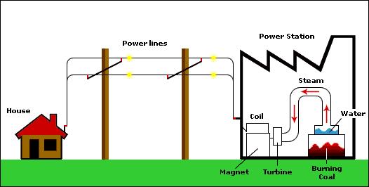
3 Alternating Voltage If the direction of current and voltage value of a source change due to time, then it is called an AC voltage. The grid uses AC, since the generation and converting to mechanical energy of it is easy and efficient, moreover the loss in tranfer is less than DC. 3
4 Alternating Voltage 4
5 Alternating Voltage The change of the voltage in grid is defined with a sine function. V AV ( t) Vmax sin( 2 ft) The parameters in this equation are; a) f is oscillation (frequency) b) V max is the maximum value of the voltage (amplitude). Frequency or oscillation of a signal is the value of repetition observed in a changing signal in unit time. In other words, frequency refers how often an evvalue of the fequency of the grid in Turkey is ent occurs. The 50 [Hertz]. [1/s ] is also used instead of [Hertz]. The time needed to complete one cycle is a period. Period is 1/f, so the period of the grid is 0.02 [s] in Turkey. Voltage of the grid. 5
6 Alternating Voltage 6
![Alternating Voltage The maximum value or the amplitude of the alternating voltage is the maximum value of the sine wave during one period. This value is approximately 311 [V] for the grid.](/docs-images/76/73880854/images/7-1.jpg "But, this value is not used as nominal value. Instead, the RMS value of this sine wave is used. The RMS value may be said as the equivalent value of an alternating voltage to direct voltage.")
7 Alternating Voltage The maximum value or the amplitude of the alternating voltage is the maximum value of the sine wave during one period. This value is approximately 311 [V] for the grid. But, this value is not used as nominal value. Instead, the RMS value of this sine wave is used. The RMS value may be said as the equivalent value of an alternating voltage to direct voltage. The effective value of a signal is: f RMS ( t) 1 T T 0 f 2 ( t) dt V V max RMS. 707 V max 2 0 For the electrical grid, the effective value is app times of the maximum voltage value of the grid and it is 220 [v]. 7
8 Alternatif Gerilim

9 Phase An important point in operations of two time dependent signals is whether they are synchronized or not. For electrical definitions, two voltage signals or two corrent signals or one voltage with one current signals can be either synchronized or with phase diference. If two signals are synchronized, they both pass the zero points and the maximum value points at the same time. 9
10 Phase If two signals pass the zero points and maximum value points in different moments then a phase shift occurs. Phase or phase shift is the time difference between two signals. The phase shift or phase is denoted with degree in sine functions. If one of the two sine functions is accepted as reference signal; the value of angle of the signal that is not the reference signal when the reference signal reaches zero is the phase value. Accordingly, and 0 degrees of phase shifts are shown in the figure below. 10
11 Phase 11
12 Phasor Representaion of AC In order to define the affects of the alternating current to a circuit, frequency, amplitude and phase need to be known. Frequency depends on the electrical grid, so the country or region. So, the voltage/current functions can be defined depending on two parameters. One of the choice in modeling alternating current / voltage is to represent them using rotating vectors (i.e. phasors). 12
13 Phasor Representaion of AC The projection of a rotating vector around origin in cartesian coordinate system is a sine function as can be seen in figure above. The length (or the radius) of the rotating vector is the amplitude of alternating voltage in this representaion. Similarly, the angle between the vector and the horizantal axis is the phase value (θ). The angular velocity of this rotating vector is the frequency of alternating voltage. 13
14 Phasor Representaion of AC 14
15 Phasor Representaion of AC A complex number is a mathematical quantity representing two dimensions of magnitude and direction. Representation of alternating voltage as a rotating vector indicates a complex number in means of mathematics. As known, complex numbers has two parts called real and imaginary which are represented in complex plane. The common representation of a complex number in cartesian form is equation (1) whereas phasor representation that is representation of a complex number as a rotating vector and more used in electrical circuit analysis is the equation (2) below. z a bi (1) z r (2) 15

 a 1 tg")
16 Phasor Representaion of AC z a bi z r b ( ) a 1 tg 2 2 r a b 16
17 Phasor Representaion of AC Four basic operations in complex numbers can be seen below. z z a a ) ( b b ) i 1 2 ( z z a a ) ( b b ) i 1 2 ( z z 1 z2 r1 r z2 r1 r2 1 2 Implementation of complex number arithmetics to voltage/current signals is examination of total effects of voltage/current sources which have different phases. Before calculating this effect, the state of the two rotating vectors, which have different phases, according to each other should be understood. This relation might be described as vectors which have the same starting point but have different angles respect to the horizontal line. 17
18 Phasor Representaion of AC 18

19 Phasor Representaion of AC Created by a combination of current/voltage sources connected to the same circuit is determined by the complex numbers, addition and subtraction operations. 19


 Coil")
20 Behaviors of Basic Circuit Components under AC Resistance (R) Coil (L) (Inductance) 20 Capacitance (C) (Capacitor)
 V R I V I R max sin( wt) According to equations above, there is no phase shift between current and voltage on a resistor.")
21 Behaviors of Basic Circuit Components under AC Resistance (R) Ohm s Law can be used for resistance under the influence of alternating voltage. V V max sin( wt) V R I V I R max sin( wt) According to equations above, there is no phase shift between current and voltage on a resistor. Nevertheles, the amplitude changes due to Ohm s Law. 21
22 Behaviors of Basic Circuit Components under AC Coil (L) (Inductor) In contrast with resistors, coils under alternating voltage resists against alternating current. The voltage on a coil (the voltage measured between two terminals) can be calculated using Lenz Law. di( t) V( t) L dt If this equation is studied considering the alternating current, the ralationship between the current and voltage might be predicted. 22
 can be calculated using Lenz Law.")
23 Behaviors of Basic Circuit Components under AC Coil (L) (Inductance) In contrast with resistors, coils under alternating voltage resists against alternating current. The voltage on a coil (the voltage measured between two terminals) can be calculated using Lenz Law. di( t) V( t) L dt If this equation is studied considering the alternating current, the ralationship between the current and voltage might be predicted. I( t) Imax sin( wt) di( t) V( t) L Lcos( wt) dt 23
24 Behaviors of Basic Circuit Components under AC 24
25 Behaviors of Basic Circuit Components under AC This result shows us that there is a 90 degrees of phase shift between voltage and current on a coil under AC. The voltage leads current by phase angle of 90 degree. The phase shift results with negative electrical power. Negative power denotes that the coil transfer power to the circuit. The resistance of coils changes due to time or frequency. This is called as reactance (inductive reactance X L ) for this reason. X L wl X L 2 fl 25
26 Behaviors of Basic Circuit Components under AC Ohm s Law might be implemented easily to alternating current circuits using quantity, the reactance. In that case, the calculations should be made using complex numbers instead of scalars. X V I XL I V X A Now, let us calculate the influence of total resistance of a resistor and a coil adding a 5 [Ohm] resistor to this circuit. 26

27 Behaviors of Basic Circuit Components under AC Resistor value: R 5 0j Inductive reactance of the coil The total effect is called as impedance. 27 X L j Z R X j L Commonly, impedance in alternating voltage circuits is the corresponding definition of resistance. Besides, it can be used as resistor in Ohm s Law as mentioned above.
28 Behaviors of Basic Circuit Components under AC V Z I Z R X j L 10 0 I A
29 Behaviors of Basic Circuit Components under AC 29
30 Behaviors of Basic Circuit Components under AC Parallel circuit 30
31 Behaviors of Basic Circuit Components under AC First state: 31
32 Behaviors of Basic Circuit Components under AC Implementing the Ohm s Law; 32
33 Behaviors of Basic Circuit Components under AC Implementing the Ohm s Law; 33
34 Behaviors of Basic Circuit Components under AC The impedance equation of parallel circuits: 34

35
Chapter 30 Inductance, Electromagnetic. Copyright 2009 Pearson Education, Inc.
 Chapter 30 Inductance, Electromagnetic Oscillations, and AC Circuits 30-7 AC Circuits with AC Source Resistors, capacitors, and inductors have different phase relationships between current and voltage
Chapter 33. Alternating Current Circuits
 Chapter 33 Alternating Current Circuits Alternating Current Circuits Electrical appliances in the house use alternating current (AC) circuits. If an AC source applies an alternating voltage to a series
Circuit Analysis-II. Circuit Analysis-II Lecture # 2 Wednesday 28 th Mar, 18
 Circuit Analysis-II Angular Measurement Angular Measurement of a Sine Wave ü As we already know that a sinusoidal voltage can be produced by an ac generator. ü As the windings on the rotor of the ac generator
Physics 132 Quiz # 23
 Name (please (please print) print) Physics 132 Quiz # 23 I. I. The The current in in an an ac ac circuit is is represented by by a phasor.the value of of the the current at at some time time t t is is
THE SINUSOIDAL WAVEFORM
 Chapter 11 THE SINUSOIDAL WAVEFORM The sinusoidal waveform or sine wave is the fundamental type of alternating current (ac) and alternating voltage. It is also referred to as a sinusoidal wave or, simply,
Electricity & Optics
 Physics 24100 Electricity & Optics Lecture 19 Chapter 29 sec. 1,2,5 Fall 2017 Semester Professor Koltick Series and Parallel R and L Resistors and inductors in series: R series = R 1 + R 2 L series = L
Exercise 1: Series RLC Circuits
 RLC Circuits AC 2 Fundamentals Exercise 1: Series RLC Circuits EXERCISE OBJECTIVE When you have completed this exercise, you will be able to analyze series RLC circuits by using calculations and measurements.
Bakiss Hiyana binti Abu Bakar JKE, POLISAS BHAB
 1 Bakiss Hiyana binti Abu Bakar JKE, POLISAS 1. Explain AC circuit concept and their analysis using AC circuit law. 2. Apply the knowledge of AC circuit in solving problem related to AC electrical circuit.
Chapter 6: Alternating Current. An alternating current is an current that reverses its direction at regular intervals.
 Chapter 6: Alternating Current An alternating current is an current that reverses its direction at regular intervals. Overview Alternating Current Phasor Diagram Sinusoidal Waveform A.C. Through a Resistor
Alternating current circuits- Series RLC circuits
 FISI30 Física Universitaria II Professor J.. ersosimo hapter 8 Alternating current circuits- Series circuits 8- Introduction A loop rotated in a magnetic field produces a sinusoidal voltage and current.
Chapter 31 Alternating Current
 Chapter 31 Alternating Current In this chapter we will learn how resistors, inductors, and capacitors behave in circuits with sinusoidally vary voltages and currents. We will define the relationship between
PHYSICS - CLUTCH CH 29: ALTERNATING CURRENT.
 !! www.clutchprep.com CONCEPT: ALTERNATING VOLTAGES AND CURRENTS BEFORE, we only considered DIRECT CURRENTS, currents that only move in - NOW we consider ALTERNATING CURRENTS, currents that move in Alternating
An induced emf is the negative of a changing magnetic field. Similarly, a self-induced emf would be found by
 This is a study guide for Exam 4. You are expected to understand and be able to answer mathematical questions on the following topics. Chapter 32 Self-Induction and Induction While a battery creates an
AC Circuit. What is alternating current? What is an AC circuit?
 Chapter 21 Alternating Current Circuits and Electromagnetic Waves 1. Alternating Current 2. Resistor in an AC circuit 3. Capacitor in an AC circuit 4. Inductor in an AC circuit 5. RLC series circuit 6.
Chapter 11. Alternating Current
 Unit-2 ECE131 BEEE Chapter 11 Alternating Current Objectives After completing this chapter, you will be able to: Describe how an AC voltage is produced with an AC generator (alternator) Define alternation,
Lecture Outline Chapter 24. Physics, 4 th Edition James S. Walker. Copyright 2010 Pearson Education, Inc.
 Lecture Outline Chapter 24 Physics, 4 th Edition James S. Walker Chapter 24 Alternating-Current Circuits Units of Chapter 24 Alternating Voltages and Currents Capacitors in AC Circuits RC Circuits Inductors
CHAPTER 2. Basic Concepts, Three-Phase Review, and Per Unit
 CHAPTER 2 Basic Concepts, Three-Phase Review, and Per Unit 1 AC power versus DC power DC system: - Power delivered to the load does not fluctuate. - If the transmission line is long power is lost in the
Chapter 6: Alternating Current
 hapter 6: Alternating urrent 6. Alternating urrent.o 6.. Define alternating current (A) An alternating current (A) is the electrical current which varies periodically with time in direction and magnitude.
AC Circuit Analysis. The Sine Wave CHAPTER 3. This chapter discusses basic concepts in the analysis of AC circuits.
 CHAPTER 3 AC Circuit Analysis This chapter discusses basic concepts in the analysis of AC circuits. The Sine Wave AC circuit analysis usually begins with the mathematical expression for a sine wave: v(t)
Electromagnetic Oscillations and Currents. March 23, 2014 Chapter 30 1
 Electromagnetic Oscillations and Currents March 23, 2014 Chapter 30 1 Driven LC Circuit! The voltage V can be thought of as the projection of the vertical axis of the phasor V m representing the time-varying
CHAPTER 9. Sinusoidal Steady-State Analysis
 CHAPTER 9 Sinusoidal Steady-State Analysis 9.1 The Sinusoidal Source A sinusoidal voltage source (independent or dependent) produces a voltage that varies sinusoidally with time. A sinusoidal current source
AC Circuits. Nikola Tesla
 AC Circuits Nikola Tesla 1856-1943 Mar 26, 2012 Alternating Current Circuits Electrical appliances in the house use alternating current (AC) circuits. If an AC source applies an alternating voltage of
CHAPTER 6: ALTERNATING CURRENT
 CHAPTER 6: ALTERNATING CURRENT PSPM II 2005/2006 NO. 12(C) 12. (c) An ac generator with rms voltage 240 V is connected to a RC circuit. The rms current in the circuit is 1.5 A and leads the voltage by
Exercise 9: inductor-resistor-capacitor (LRC) circuits
 circuits") Exercise 9: inductor-resistor-capacitor (LRC) circuits Purpose: to study the relationship of the phase and resonance on capacitor and inductor reactance in a circuit driven by an AC signal. Introduction
Exercise 9: inductor-resistor-capacitor (LRC) circuits Purpose: to study the relationship of the phase and resonance on capacitor and inductor reactance in a circuit driven by an AC signal. Introduction
ELECTROMAGNETIC INDUCTION AND ALTERNATING CURRENT (Assignment)
") ELECTROMAGNETIC INDUCTION AND ALTERNATING CURRENT (Assignment) 1. In an A.C. circuit A ; the current leads the voltage by 30 0 and in circuit B, the current lags behind the voltage by 30 0. What is the
ELECTROMAGNETIC INDUCTION AND ALTERNATING CURRENT (Assignment) 1. In an A.C. circuit A ; the current leads the voltage by 30 0 and in circuit B, the current lags behind the voltage by 30 0. What is the
Chapter 33. Alternating Current Circuits
 Chapter 33 Alternating Current Circuits C HAP T E O UTLI N E 33 1 AC Sources 33 2 esistors in an AC Circuit 33 3 Inductors in an AC Circuit 33 4 Capacitors in an AC Circuit 33 5 The L Series Circuit 33
LECTURE 19. Alternating Current Generators (DEMO)
") ETURE 9 A Generators A ircuits Start by considering simple circuits with one element (R,, or ) in addition to the driving emf. It will lead to Oscillations and Driven R circuits Alternating urrent Generators
ETURE 9 A Generators A ircuits Start by considering simple circuits with one element (R,, or ) in addition to the driving emf. It will lead to Oscillations and Driven R circuits Alternating urrent Generators
Physics for Scientists & Engineers 2 2 = 1 LC. Review ( ) Review (2) Review (3) e! Rt. cos "t + # ( ) q = q max. Spring Semester 2005 Lecture 30 U E
 Review (2) Review (3) e! Rt. cos t + # ( ) q = q max. Spring Semester 2005 Lecture 30 U E") Review hysics for Scientists & Engineers Spring Semester 005 Lecture 30! If we have a single loop RLC circuit, the charge in the circuit as a function of time is given by! Where q = q max e! Rt L cos "t
Review hysics for Scientists & Engineers Spring Semester 005 Lecture 30! If we have a single loop RLC circuit, the charge in the circuit as a function of time is given by! Where q = q max e! Rt L cos "t
QUESTION BANK ETE (17331) CM/IF. Chapter1: DC Circuits
 CM/IF. Chapter1: DC Circuits") QUESTION BANK ETE (17331) CM/IF Chapter1: DC Circuits Q1. State & explain Ohms law. Also explain concept of series & parallel circuit with the help of diagram. 3M Q2. Find the value of resistor in fig.
QUESTION BANK ETE (17331) CM/IF Chapter1: DC Circuits Q1. State & explain Ohms law. Also explain concept of series & parallel circuit with the help of diagram. 3M Q2. Find the value of resistor in fig.
10. Introduction and Chapter Objectives
 Real Analog - Circuits Chapter 0: Steady-state Sinusoidal Analysis 0. Introduction and Chapter Objectives We will now study dynamic systems which are subjected to sinusoidal forcing functions. Previously,
Simple AC Circuits. Introduction
 Simple AC Circuits Introduction Each problem in this problem set involves the steady state response of a linear, time-invariant circuit to a single sinusoidal input. Such a response is known to be sinusoidal
Experiment 1 Alternating Current with Coil and Ohmic Resistors
 Experiment Alternating Current with Coil and Ohmic esistors - Objects of the experiment - Determining the total impedance and the phase shift in a series connection of a coil and a resistor. - Determining
AC Sources and Phasors
 AC Sources and Phasors Circuits powered by a sinusoidal emf are called AC circuits, where AC stands for alternating current. Steady-current circuits are called DC circuits, for direct current. The instantaneous
1. If the flux associated with a coil varies at the rate of 1 weber/min,the induced emf is
 1. f the flux associated with a coil varies at the rate of 1 weber/min,the induced emf is 1 1. 1V 2. V 60 3. 60V 4. Zero 2. Lenz s law is the consequence of the law of conservation of 1. Charge 2. Mass
AC Theory, Circuits, Generators & Motors
 PDH-Pro.com AC Theory, Circuits, Generators & Motors Course Number: EE-02-306 PDH: 6 Approved for: AK, AL, AR, GA, IA, IL, IN, KS, KY, MD, ME, MI, MN, MO, MS, MT, NC, ND, NE, NH, NJ, NM, NV, OH, OK, OR,
11. AC-resistances of capacitor and inductors: Reactances.
 11. AC-resistances of capacitor and inductors: Reactances. Purpose: To study the behavior of the AC voltage signals across elements in a simple series connection of a resistor with an inductor and with
ECE215 Lecture 7 Date:
 Lecture 7 Date: 29.08.2016 AC Circuits: Impedance and Admittance, Kirchoff s Laws, Phase Shifter, AC bridge Impedance and Admittance we know: we express Ohm s law in phasor form: where Z is a frequency-dependent
DC and AC Circuits. Objective. Theory. 1. Direct Current (DC) R-C Circuit
 R-C Circuit") [International Campus Lab] Objective Determine the behavior of resistors, capacitors, and inductors in DC and AC circuits. Theory ----------------------------- Reference -------------------------- Young
[International Campus Lab] Objective Determine the behavior of resistors, capacitors, and inductors in DC and AC circuits. Theory ----------------------------- Reference -------------------------- Young
Worksheet for Exploration 31.1: Amplitude, Frequency and Phase Shift
 Worksheet for Exploration 31.1: Amplitude, Frequency and Phase Shift We characterize the voltage (or current) in AC circuits in terms of the amplitude, frequency (period) and phase. The sinusoidal voltage
PHYSICS WORKSHEET CLASS : XII. Topic: Alternating current
 PHYSICS WORKSHEET CLASS : XII Topic: Alternating current 1. What is mean by root mean square value of alternating current? 2. Distinguish between the terms effective value and peak value of an alternating
UNIVERSITY OF BABYLON BASIC OF ELECTRICAL ENGINEERING LECTURE NOTES. Resonance
 Resonance The resonant(or tuned) circuit, in one of its many forms, allows us to select a desired radio or television signal from the vast number of signals that are around us at any time. Resonant electronic
AC Fundamental. Simple Loop Generator: Whenever a conductor moves in a magnetic field, an emf is induced in it.
 AC Fundamental Simple Loop Generator: Whenever a conductor moves in a magnetic field, an emf is induced in it. Fig.: Simple Loop Generator The amount of EMF induced into a coil cutting the magnetic lines
AP Physics C. Alternating Current. Chapter Problems. Sources of Alternating EMF
 AP Physics C Alternating Current Chapter Problems Sources of Alternating EMF 1. A 10 cm diameter loop of wire is oriented perpendicular to a 2.5 T magnetic field. What is the magnetic flux through the
Electrical Theory. Power Principles and Phase Angle. PJM State & Member Training Dept. PJM /22/2018
 Electrical Theory Power Principles and Phase Angle PJM State & Member Training Dept. PJM 2018 Objectives At the end of this presentation the learner will be able to: Identify the characteristics of Sine
Goals. Introduction. To understand the use of root mean square (rms) voltages and currents.
 voltages and currents.") Lab 10. AC Circuits Goals To show that AC voltages cannot generally be added without accounting for their phase relationships. That is, one must account for how they vary in time with respect to one another.
Lab 10. AC Circuits Goals To show that AC voltages cannot generally be added without accounting for their phase relationships. That is, one must account for how they vary in time with respect to one another.
Experiment 9 AC Circuits
 Experiment 9 AC Circuits "Look for knowledge not in books but in things themselves." W. Gilbert (1540-1603) OBJECTIVES To study some circuit elements and a simple AC circuit. THEORY All useful circuits
Hours / 100 Marks Seat No.
 17323 14115 3 Hours / 100 Seat No. Instructions (1) All Questions are Compulsory. (2) Illustrate your answers with neat sketches wherever necessary. (3) Figures to the right indicate full marks. (4) Assume
Chapter 31. Alternating Current. PowerPoint Lectures for University Physics, 14th Edition Hugh D. Young and Roger A. Freedman Lectures by Jason Harlow
 Chapter 31 Alternating Current PowerPoint Lectures for University Physics, 14th Edition Hugh D. Young and Roger A. Freedman Lectures by Jason Harlow Learning Goals for Chapter 31 Looking forward at How
Phasor. Phasor Diagram of a Sinusoidal Waveform
 Phasor A phasor is a vector that has an arrow head at one end which signifies partly the maximum value of the vector quantity ( V or I ) and partly the end of the vector that rotates. Generally, vectors
13. Magnetically Coupled Circuits
 13. Magnetically Coupled Circuits The change in the current flowing through an inductor induces (creates) a voltage in the conductor itself (self-inductance) and in any nearby conductors (mutual inductance)
Exercise 2: Parallel RLC Circuits
 RLC Circuits AC 2 Fundamentals Exercise 2: Parallel RLC Circuits EXERCSE OBJECTVE When you have completed this exercise, you will be able to analyze parallel RLC circuits by using calculations and measurements.
Transmission Line Models Part 1
 Transmission Line Models Part 1 Unlike the electric machines studied so far, transmission lines are characterized by their distributed parameters: distributed resistance, inductance, and capacitance. The
AC Circuits. "Look for knowledge not in books but in things themselves." W. Gilbert ( )
") AC Circuits "Look for knowledge not in books but in things themselves." W. Gilbert (1540-1603) OBJECTIVES To study some circuit elements and a simple AC circuit. THEORY All useful circuits use varying
AC Circuits "Look for knowledge not in books but in things themselves." W. Gilbert (1540-1603) OBJECTIVES To study some circuit elements and a simple AC circuit. THEORY All useful circuits use varying
Goals. Introduction. To understand the use of root mean square (rms) voltages and currents.
 voltages and currents.") Lab 10. AC Circuits Goals To show that AC voltages cannot generally be added without accounting for their phase relationships. That is, one must account for how they vary in time with respect to one another.
Lab 10. AC Circuits Goals To show that AC voltages cannot generally be added without accounting for their phase relationships. That is, one must account for how they vary in time with respect to one another.
Basic Analog Circuits
 Basic Analog Circuits Overview This tutorial is part of the National Instruments Measurement Fundamentals series. Each tutorial in this series, will teach you a specific topic of common measurement applications,
Chapter 21. Alternating Current Circuits and Electromagnetic Waves
 Chapter 21 Alternating Current Circuits and Electromagnetic Waves AC Circuit An AC circuit consists of a combination of circuit elements and an AC generator or source The output of an AC generator is sinusoidal
AC reactive circuit calculations
 AC reactive circuit calculations This worksheet and all related files are licensed under the Creative Commons Attribution License, version 1.0. To view a copy of this license, visit http://creativecommons.org/licenses/by/1.0/,
Physics Jonathan Dowling. Lecture 35: MON 16 NOV Electrical Oscillations, LC Circuits, Alternating Current II
 hysics 2113 Jonathan Dowling Lecture 35: MON 16 NOV Electrical Oscillations, LC Circuits, Alternating Current II Damped LCR Oscillator Ideal LC circuit without resistance: oscillations go on forever; ω
PHYS 1442 Section 004 Lecture #15
 PHYS 1442 Section 004 Lecture #15 Monday March 17, 2014 Dr. Andrew Brandt Chapter 21 Generator Transformer Inductance 3/17/2014 1 PHYS 1442-004, Dr. Andrew Brandt Announcements HW8 on Ch 21-22 will be
Look over Chapter 31 sections 1-4, 6, 8, 9, 10, 11 Examples 1-8. Look over Chapter 21 sections Examples PHYS 2212 PHYS 1112
 PHYS 2212 Look over Chapter 31 sections 1-4, 6, 8, 9, 10, 11 Examples 1-8 PHYS 1112 Look over Chapter 21 sections 11-14 Examples 16-18 Good Things To Know 1) How AC generators work. 2) How to find the
A Practical Exercise Name: Section:
 AC Thèvenin Updated 17 AUG 2016 A Practical Exercise Name: Section: I. Purpose. 1. Review the construction and analysis of AC circuits using a DMM and/or oscilloscope. 2. Introduce the AC Thèvenin equivalent
No Brain Too Small PHYSICS
 ELECTRICITY: AC QUESTIONS No Brain Too Small PHYSICS MEASURING IRON IN SAND (2016;3) Vivienne wants to measure the amount of iron in ironsand mixtures collected from different beaches. The diagram below
AC Theory and Electronics
 AC Theory and Electronics An Alternating Current (AC) or Voltage is one whose amplitude is not constant, but varies with time about some mean position (value). Some examples of AC variation are shown below:
Real Analog Chapter 10: Steady-state Sinusoidal Analysis
 1300 Henley Court Pullman, WA 99163 509.334.6306 www.store. digilent.com Real Analog Chapter 10: Steadystate Sinusoidal Analysis 10 Introduction and Chapter Objectives We will now study dynamic systems
Be sure to bring your student ID card and your own two-page (two-side) crib sheet, one from exam 1 and a new one.
 crib sheet, one from exam 1 and a new one.") ANNOUNCEMENT *Exam 2: Monday, November 5, 2012, 8 PM - 10 PM *Location: Elliot Hall of Music *Covers all readings, lectures, homework from Chapters 25 through 28. *The exam will be multiple choice (15-18
ANNOUNCEMENT *Exam 2: Monday, November 5, 2012, 8 PM - 10 PM *Location: Elliot Hall of Music *Covers all readings, lectures, homework from Chapters 25 through 28. *The exam will be multiple choice (15-18
EE42: Running Checklist of Electronics Terms Dick White
 EE42: Running Checklist of Electronics Terms 14.02.05 Dick White Terms are listed roughly in order of their introduction. Most definitions can be found in your text. Terms2 TERM Charge, current, voltage,
Experiment 1 LRC Transients
 Physics 263 Experiment 1 LRC Transients 1 Introduction In this experiment we will study the damped oscillations and other transient waveforms produced in a circuit containing an inductor, a capacitor,
Lab E5: Filters and Complex Impedance
 E5.1 Lab E5: Filters and Complex Impedance Note: It is strongly recommended that you complete lab E4: Capacitors and the RC Circuit before performing this experiment. Introduction Ohm s law, a well known
RLC Frequency Response
 1. Introduction RLC Frequency Response The student will analyze the frequency response of an RLC circuit excited by a sinusoid. Amplitude and phase shift of circuit components will be analyzed at different
EXPERIMENT 8: LRC CIRCUITS
 EXPERIMENT 8: LRC CIRCUITS Equipment List S 1 BK Precision 4011 or 4011A 5 MHz Function Generator OS BK 2120B Dual Channel Oscilloscope V 1 BK 388B Multimeter L 1 Leeds & Northrup #1532 100 mh Inductor
AC CIRCUITS. Part 1: Inductance of a Coil. THEORY: If the current in a resistor R, a capacitor C, and/or an inductor L is given by:
 AC CIRCUITS OBJECTIVE: To study the effect of alternating currents on various electrical quantities in circuits containing resistors, capacitors and inductors. Part 1: Inductance of a Coil THEORY: If the
Chapter 25 Alternating Currents
 Chapter 25 Alternating Currents GOALS When you have mastered the contents of this chapter, you will be able to achieve the following goals: Definitions Define each of the following terms and use it in
UNIVERSITY OF BOLTON SCHOOL OF SPORT AND BIOMEDICAL SCIENCE. BEng (HONS)/MEng BIOMEDICAL ENGINEERING. BEng (HONS) MEDICAL ENGINEERING
/MEng BIOMEDICAL ENGINEERING. BEng (HONS) MEDICAL ENGINEERING") LH29 SCHOOL OF SPORT AND BIOMEDICAL SCIENCE BEng (HONS)/MEng BIOMEDICAL ENGINEERING BEng (HONS) MEDICAL ENGINEERING SEMESTER 2 EXAMINATIONS 2015/2016 MODULE NO: BME4004 Date: Wednesday 18 May 2016 Time:
LH29 SCHOOL OF SPORT AND BIOMEDICAL SCIENCE BEng (HONS)/MEng BIOMEDICAL ENGINEERING BEng (HONS) MEDICAL ENGINEERING SEMESTER 2 EXAMINATIONS 2015/2016 MODULE NO: BME4004 Date: Wednesday 18 May 2016 Time:
RC circuit. Recall the series RC circuit.
 RC circuit Recall the series RC circuit. If C is discharged and then a constant voltage V is suddenly applied, the charge on, and voltage across, C is initially zero. The charge ultimately reaches the
Figure 1: Closed Loop System
 SIGNAL GENERATORS 3. Introduction Signal sources have a variety of applications including checking stage gain, frequency response, and alignment in receivers and in a wide range of other electronics equipment.
Alternating Current. Slide 1 / 69. Slide 2 / 69. Slide 3 / 69. Topics to be covered. Sources of Alternating EMF. Sources of alternating EMF
 Slide 1 / 69 lternating urrent Sources of alternating EMF Transformers ircuits and Impedance Topics to be covered Slide 2 / 69 LR Series ircuits Resonance in ircuit Oscillations Sources of lternating EMF
Alternating Current. Slide 2 / 69. Slide 1 / 69. Slide 3 / 69. Slide 4 / 69. Slide 6 / 69. Slide 5 / 69. Topics to be covered
 Slide 1 / 69 lternating urrent Sources of alternating EMF ircuits and Impedance Slide 2 / 69 Topics to be covered LR Series ircuits Resonance in ircuit Oscillations Slide 3 / 69 Sources of lternating EMF
AC CURRENTS, VOLTAGES, FILTERS, and RESONANCE
 July 22, 2008 AC Currents, Voltages, Filters, Resonance 1 Name Date Partners AC CURRENTS, VOLTAGES, FILTERS, and RESONANCE V(volts) t(s) OBJECTIVES To understand the meanings of amplitude, frequency, phase,
CIRCLE DIAGRAMS. Learning Objectives. Combinations of R and C circuits
 H A P T E R18 earning Objectives ircle Diagram of a Series ircuit Rigorous Mathematical Treatment onstant Resistance but ariable Reactance Properties of onstant Reactance But ariable Resistance ircuit
A.C. Circuits -- Conceptual Solutions
 A.C. Circuits -- Conceptual Solutions 1.) Charge carriers in a DC circuit move in one direction only. What do charge carriers do in an AC circuit? Solution: The voltage difference between the terminals
Sirindhorn International Institute of Technology Thammasat University
 Sirindhorn International Institute of Technology Thammasat University School of Information, Computer and Communication Technology COURSE : ECS 34 Basic Electrical Engineering Lab INSTRUCTOR : Dr. Prapun
Basic Electronics Learning by doing Prof. T.S. Natarajan Department of Physics Indian Institute of Technology, Madras
 Basic Electronics Learning by doing Prof. T.S. Natarajan Department of Physics Indian Institute of Technology, Madras Lecture 26 Mathematical operations Hello everybody! In our series of lectures on basic
AC Circuits INTRODUCTION DISCUSSION OF PRINCIPLES. Resistance in an AC Circuit
 AC Circuits INTRODUCTION The study of alternating current 1 (AC) in physics is very important as it has practical applications in our daily lives. As the name implies, the current and voltage change directions
LCR CIRCUITS Institute of Lifelong Learning, University of Delhi
 L UTS nstitute of Lifelong Learning, University of Delhi L UTS PHYSS (LAB MANUAL) nstitute of Lifelong Learning, University of Delhi PHYSS (LAB MANUAL) L UTS ntroduction ircuits containing an inductor
Alternating voltages and currents
 Alternating voltages and currents Introduction - Electricity is produced by generators at power stations and then distributed by a vast network of transmission lines (called the National Grid system) to
Two-Port Networks and Filters
 Two-Port Networks and Filters Filters By combining resistors capacitors and inductors in special ways you can design networks that are capable of passing certain frequencies of signals while rejecting
Solution: All electromagnetic waves in vacuum, regardless of their wavelength or frequency, travel at the speed of light, c.
 1. Two electromagnetic waves travel through empty space. Wave A as a wavelength of 700 nm (red light), while Wave B has a wavelength of 400 nm (blue light). Which statement is true? A) Wave A travels faster
Lab 9 AC FILTERS AND RESONANCE
 09-1 Name Date Partners ab 9 A FITES AND ESONANE OBJETIES OEIEW To understand the design of capacitive and inductive filters To understand resonance in circuits driven by A signals In a previous lab, you
University of Jordan School of Engineering Electrical Engineering Department. EE 219 Electrical Circuits Lab
 University of Jordan School of Engineering Electrical Engineering Department EE 219 Electrical Circuits Lab EXPERIMENT 7 RESONANCE Prepared by: Dr. Mohammed Hawa EXPERIMENT 7 RESONANCE OBJECTIVE This experiment
15. the power factor of an a.c circuit is.5 what will be the phase difference between voltage and current in this
 1 1. In a series LCR circuit the voltage across inductor, a capacitor and a resistor are 30 V, 30 V and 60 V respectively. What is the phase difference between applied voltage and current in the circuit?
Lecture 3 Complex Exponential Signals
 Lecture 3 Complex Exponential Signals Fundamentals of Digital Signal Processing Spring, 2012 Wei-Ta Chu 2012/3/1 1 Review of Complex Numbers Using Euler s famous formula for the complex exponential The
332:223 Principles of Electrical Engineering I Laboratory Experiment #2 Title: Function Generators and Oscilloscopes Suggested Equipment:
 RUTGERS UNIVERSITY The State University of New Jersey School of Engineering Department Of Electrical and Computer Engineering 332:223 Principles of Electrical Engineering I Laboratory Experiment #2 Title:
Lab 10 - INTRODUCTION TO AC FILTERS AND RESONANCE
 159 Name Date Partners Lab 10 - INTRODUCTION TO AC FILTERS AND RESONANCE OBJECTIVES To understand the design of capacitive and inductive filters To understand resonance in circuits driven by AC signals
EXPERIMENT 4: RC, RL and RD CIRCUITs
 EXPERIMENT 4: RC, RL and RD CIRCUITs Equipment List An assortment of resistor, one each of (330, 1k,1.5k, 10k,100k,1000k) Function Generator Oscilloscope 0.F Ceramic Capacitor 100H Inductor LED and 1N4001
RLC Circuits. Centre College. Physics 230 Lab 8
 ircuits entre ollege Phsics 230 ab 8 1 Preliminaries Objective To stud the electrical characteristics of an alternating current circuit containing a resistor, inductor, and capacitor. Equipment Oscilloscope,
Lab 9 - INTRODUCTION TO AC CURRENTS AND VOLTAGES
 145 Name Date Partners Lab 9 INTRODUCTION TO AC CURRENTS AND VOLTAGES V(volts) t(s) OBJECTIVES To learn the meanings of peak voltage and frequency for AC signals. To observe the behavior of resistors in
Exercise 1: Inductive Reactance
 nductive Reactance Exercise 1: nductive Reactance EERCSE OBJECTE When you have completed this exercise, you will be able to determine inductive reactance ( L ) by using calculated and measured values.
ENGINEERING COUNCIL CERTIFICATE LEVEL ENGINEERING SCIENCE C103 TUTORIAL 18 ALTERNATING CURRENT
 ENGINEERING OUNIL ERTIFIATE LEVEL ENGINEERING SIENE 03 TUTORIAL 8 ALTERNATING URRENT On completion of this tutorial you should be able to do the following. Explain alternating current. Explain Root Mean
RLC-circuits with Cobra4 Xpert-Link TEP. 1 2 π L C. f res=
 Related topics Damped and forced oscillations, Kirchhoff s laws, series and parallel tuned circuit, resistance, capacitance, inductance, reactance, impedance, phase displacement, Q-factor, band-width Principle
Electrical Circuits (2)
") Electrical Circuits (2) Lecture 1 Intro. & Review Dr.Eng. Basem ElHalawany Course Info Title Electric Circuits (2) Lecturer: Lecturer Webpage: Teaching Assistant (TA) Course Webpage References Software
Electrical Circuits (2) Lecture 1 Intro. & Review Dr.Eng. Basem ElHalawany Course Info Title Electric Circuits (2) Lecturer: Lecturer Webpage: Teaching Assistant (TA) Course Webpage References Software